EP3779323A1 - Air conditioning system control device, outdoor unit, relay unit, heat source unit, and air conditioning system - Google Patents
Air conditioning system control device, outdoor unit, relay unit, heat source unit, and air conditioning system Download PDFInfo
- Publication number
- EP3779323A1 EP3779323A1 EP18913342.4A EP18913342A EP3779323A1 EP 3779323 A1 EP3779323 A1 EP 3779323A1 EP 18913342 A EP18913342 A EP 18913342A EP 3779323 A1 EP3779323 A1 EP 3779323A1
- Authority
- EP
- European Patent Office
- Prior art keywords
- heat
- heat exchanger
- pump
- air conditioning
- compressor
- Prior art date
- Legal status (The legal status is an assumption and is not a legal conclusion. Google has not performed a legal analysis and makes no representation as to the accuracy of the status listed.)
- Granted
Links
Images


Classifications
-
- F—MECHANICAL ENGINEERING; LIGHTING; HEATING; WEAPONS; BLASTING
- F25—REFRIGERATION OR COOLING; COMBINED HEATING AND REFRIGERATION SYSTEMS; HEAT PUMP SYSTEMS; MANUFACTURE OR STORAGE OF ICE; LIQUEFACTION SOLIDIFICATION OF GASES
- F25B—REFRIGERATION MACHINES, PLANTS OR SYSTEMS; COMBINED HEATING AND REFRIGERATION SYSTEMS; HEAT PUMP SYSTEMS
- F25B25/00—Machines, plants or systems, using a combination of modes of operation covered by two or more of the groups F25B1/00 - F25B23/00
- F25B25/005—Machines, plants or systems, using a combination of modes of operation covered by two or more of the groups F25B1/00 - F25B23/00 using primary and secondary systems
-
- F—MECHANICAL ENGINEERING; LIGHTING; HEATING; WEAPONS; BLASTING
- F24—HEATING; RANGES; VENTILATING
- F24F—AIR-CONDITIONING; AIR-HUMIDIFICATION; VENTILATION; USE OF AIR CURRENTS FOR SCREENING
- F24F11/00—Control or safety arrangements
- F24F11/70—Control systems characterised by their outputs; Constructional details thereof
- F24F11/80—Control systems characterised by their outputs; Constructional details thereof for controlling the temperature of the supplied air
- F24F11/83—Control systems characterised by their outputs; Constructional details thereof for controlling the temperature of the supplied air by controlling the supply of heat-exchange fluids to heat-exchangers
- F24F11/84—Control systems characterised by their outputs; Constructional details thereof for controlling the temperature of the supplied air by controlling the supply of heat-exchange fluids to heat-exchangers using valves
-
- F—MECHANICAL ENGINEERING; LIGHTING; HEATING; WEAPONS; BLASTING
- F24—HEATING; RANGES; VENTILATING
- F24F—AIR-CONDITIONING; AIR-HUMIDIFICATION; VENTILATION; USE OF AIR CURRENTS FOR SCREENING
- F24F11/00—Control or safety arrangements
- F24F11/70—Control systems characterised by their outputs; Constructional details thereof
- F24F11/80—Control systems characterised by their outputs; Constructional details thereof for controlling the temperature of the supplied air
- F24F11/83—Control systems characterised by their outputs; Constructional details thereof for controlling the temperature of the supplied air by controlling the supply of heat-exchange fluids to heat-exchangers
-
- F—MECHANICAL ENGINEERING; LIGHTING; HEATING; WEAPONS; BLASTING
- F24—HEATING; RANGES; VENTILATING
- F24F—AIR-CONDITIONING; AIR-HUMIDIFICATION; VENTILATION; USE OF AIR CURRENTS FOR SCREENING
- F24F11/00—Control or safety arrangements
- F24F11/70—Control systems characterised by their outputs; Constructional details thereof
- F24F11/80—Control systems characterised by their outputs; Constructional details thereof for controlling the temperature of the supplied air
- F24F11/86—Control systems characterised by their outputs; Constructional details thereof for controlling the temperature of the supplied air by controlling compressors within refrigeration or heat pump circuits
-
- F—MECHANICAL ENGINEERING; LIGHTING; HEATING; WEAPONS; BLASTING
- F24—HEATING; RANGES; VENTILATING
- F24F—AIR-CONDITIONING; AIR-HUMIDIFICATION; VENTILATION; USE OF AIR CURRENTS FOR SCREENING
- F24F5/00—Air-conditioning systems or apparatus not covered by F24F1/00 or F24F3/00, e.g. using solar heat or combined with household units such as an oven or water heater
-
- F—MECHANICAL ENGINEERING; LIGHTING; HEATING; WEAPONS; BLASTING
- F25—REFRIGERATION OR COOLING; COMBINED HEATING AND REFRIGERATION SYSTEMS; HEAT PUMP SYSTEMS; MANUFACTURE OR STORAGE OF ICE; LIQUEFACTION SOLIDIFICATION OF GASES
- F25B—REFRIGERATION MACHINES, PLANTS OR SYSTEMS; COMBINED HEATING AND REFRIGERATION SYSTEMS; HEAT PUMP SYSTEMS
- F25B49/00—Arrangement or mounting of control or safety devices
- F25B49/02—Arrangement or mounting of control or safety devices for compression type machines, plants or systems
-
- F—MECHANICAL ENGINEERING; LIGHTING; HEATING; WEAPONS; BLASTING
- F24—HEATING; RANGES; VENTILATING
- F24F—AIR-CONDITIONING; AIR-HUMIDIFICATION; VENTILATION; USE OF AIR CURRENTS FOR SCREENING
- F24F2110/00—Control inputs relating to air properties
- F24F2110/10—Temperature
-
- F—MECHANICAL ENGINEERING; LIGHTING; HEATING; WEAPONS; BLASTING
- F24—HEATING; RANGES; VENTILATING
- F24F—AIR-CONDITIONING; AIR-HUMIDIFICATION; VENTILATION; USE OF AIR CURRENTS FOR SCREENING
- F24F2140/00—Control inputs relating to system states
- F24F2140/20—Heat-exchange fluid temperature
-
- F—MECHANICAL ENGINEERING; LIGHTING; HEATING; WEAPONS; BLASTING
- F25—REFRIGERATION OR COOLING; COMBINED HEATING AND REFRIGERATION SYSTEMS; HEAT PUMP SYSTEMS; MANUFACTURE OR STORAGE OF ICE; LIQUEFACTION SOLIDIFICATION OF GASES
- F25B—REFRIGERATION MACHINES, PLANTS OR SYSTEMS; COMBINED HEATING AND REFRIGERATION SYSTEMS; HEAT PUMP SYSTEMS
- F25B13/00—Compression machines, plants or systems, with reversible cycle
-
- F—MECHANICAL ENGINEERING; LIGHTING; HEATING; WEAPONS; BLASTING
- F25—REFRIGERATION OR COOLING; COMBINED HEATING AND REFRIGERATION SYSTEMS; HEAT PUMP SYSTEMS; MANUFACTURE OR STORAGE OF ICE; LIQUEFACTION SOLIDIFICATION OF GASES
- F25B—REFRIGERATION MACHINES, PLANTS OR SYSTEMS; COMBINED HEATING AND REFRIGERATION SYSTEMS; HEAT PUMP SYSTEMS
- F25B2313/00—Compression machines, plants or systems with reversible cycle not otherwise provided for
- F25B2313/003—Indoor unit with water as a heat sink or heat source
-
- F—MECHANICAL ENGINEERING; LIGHTING; HEATING; WEAPONS; BLASTING
- F25—REFRIGERATION OR COOLING; COMBINED HEATING AND REFRIGERATION SYSTEMS; HEAT PUMP SYSTEMS; MANUFACTURE OR STORAGE OF ICE; LIQUEFACTION SOLIDIFICATION OF GASES
- F25B—REFRIGERATION MACHINES, PLANTS OR SYSTEMS; COMBINED HEATING AND REFRIGERATION SYSTEMS; HEAT PUMP SYSTEMS
- F25B2313/00—Compression machines, plants or systems with reversible cycle not otherwise provided for
- F25B2313/023—Compression machines, plants or systems with reversible cycle not otherwise provided for using multiple indoor units
- F25B2313/0233—Compression machines, plants or systems with reversible cycle not otherwise provided for using multiple indoor units in parallel arrangements
-
- F—MECHANICAL ENGINEERING; LIGHTING; HEATING; WEAPONS; BLASTING
- F25—REFRIGERATION OR COOLING; COMBINED HEATING AND REFRIGERATION SYSTEMS; HEAT PUMP SYSTEMS; MANUFACTURE OR STORAGE OF ICE; LIQUEFACTION SOLIDIFICATION OF GASES
- F25B—REFRIGERATION MACHINES, PLANTS OR SYSTEMS; COMBINED HEATING AND REFRIGERATION SYSTEMS; HEAT PUMP SYSTEMS
- F25B2600/00—Control issues
- F25B2600/02—Compressor control
- F25B2600/025—Compressor control by controlling speed
- F25B2600/0253—Compressor control by controlling speed with variable speed
-
- F—MECHANICAL ENGINEERING; LIGHTING; HEATING; WEAPONS; BLASTING
- F25—REFRIGERATION OR COOLING; COMBINED HEATING AND REFRIGERATION SYSTEMS; HEAT PUMP SYSTEMS; MANUFACTURE OR STORAGE OF ICE; LIQUEFACTION SOLIDIFICATION OF GASES
- F25B—REFRIGERATION MACHINES, PLANTS OR SYSTEMS; COMBINED HEATING AND REFRIGERATION SYSTEMS; HEAT PUMP SYSTEMS
- F25B2600/00—Control issues
- F25B2600/13—Pump speed control
-
- F—MECHANICAL ENGINEERING; LIGHTING; HEATING; WEAPONS; BLASTING
- F25—REFRIGERATION OR COOLING; COMBINED HEATING AND REFRIGERATION SYSTEMS; HEAT PUMP SYSTEMS; MANUFACTURE OR STORAGE OF ICE; LIQUEFACTION SOLIDIFICATION OF GASES
- F25B—REFRIGERATION MACHINES, PLANTS OR SYSTEMS; COMBINED HEATING AND REFRIGERATION SYSTEMS; HEAT PUMP SYSTEMS
- F25B2700/00—Sensing or detecting of parameters; Sensors therefor
- F25B2700/21—Temperatures
- F25B2700/2117—Temperatures of an evaporator
- F25B2700/21171—Temperatures of an evaporator of the fluid cooled by the evaporator
-
- Y—GENERAL TAGGING OF NEW TECHNOLOGICAL DEVELOPMENTS; GENERAL TAGGING OF CROSS-SECTIONAL TECHNOLOGIES SPANNING OVER SEVERAL SECTIONS OF THE IPC; TECHNICAL SUBJECTS COVERED BY FORMER USPC CROSS-REFERENCE ART COLLECTIONS [XRACs] AND DIGESTS
- Y02—TECHNOLOGIES OR APPLICATIONS FOR MITIGATION OR ADAPTATION AGAINST CLIMATE CHANGE
- Y02B—CLIMATE CHANGE MITIGATION TECHNOLOGIES RELATED TO BUILDINGS, e.g. HOUSING, HOUSE APPLIANCES OR RELATED END-USER APPLICATIONS
- Y02B30/00—Energy efficient heating, ventilation or air conditioning [HVAC]
- Y02B30/70—Efficient control or regulation technologies, e.g. for control of refrigerant flow, motor or heating
Definitions
- the present invention relates to a controller of an air conditioning system, an outdoor unit, a relay unit, a heat source apparatus, and an air conditioning system, and more specifically to a controller of an air conditioning system using a first heat medium and a second heat medium, an outdoor unit, a relay unit, a heat source apparatus, and an air conditioning system.
- an indirect air conditioning apparatus that generates hot and/or chilled water by a heat source apparatus such as a heat pump, and delivers the water to an indoor unit through a water pump and a pipe to perform heating and/or cooling in the interior of a room.
- Japanese Patent No. 5188572 discloses an air conditioning apparatus that causes a heat source-side heat medium circulating through a heat source-side circuit and a use-side heat medium circulating through a use-side circuit to exchange heat at a plurality of intermediate heat exchangers provided at a relay portion.
- Such an indirect air conditioning apparatus employs water or brine as a use-side heat medium, and thus has been receiving increasing attention in recent years in order to reduce refrigerant usage.
- the length of, and the number of bent portions of, a water pipe between an indoor unit and a relay unit vary with the arrangement of the indoor unit and the relay unit, resulting in various resistances to water flow in the pipe as well. It is thus difficult to determine the capacity of a water pump. While it is preferred to install a water pump having a sufficient capacity, it is conceivable that a water pump having a smaller capacity than is required may be installed. An insufficient capacity of the water pump may result in insufficient heating and/or cooling performance.
- the present invention has been made to solve the problem described above, and has an object to provide a controller of an air conditioning system capable of keeping heating and/or cooling performance within an appropriate range, an outdoor unit, a relay unit, a heat source apparatus, and an air conditioning system, in an indirect air conditioner using water or brine.
- the present disclosure relates to a controller of an air conditioning system.
- the air conditioning system includes: a compressor configured to compress a first heat medium; a first heat exchanger configured to exchange heat between the first heat medium and outdoor air; a second heat exchanger configured to exchange heat between the first heat medium and a second heat medium; a plurality of third heat exchangers configured to exchange heat between the second heat medium and indoor air; a plurality of flow rate control valves configured to control flow rates of the second heat medium flowing respectively in the plurality of third heat exchangers; and a pump configured to circulate the second heat medium between the plurality of third heat exchangers and the second heat exchanger.
- the controller that controls the air conditioning system is configured to raise an operation frequency of the compressor at a first time so as to increase an amount of heat exchange by the second heat exchanger.
- the controller is configured to lower the operation frequency of the compressor or lower the driving voltage of the pump.
- the present disclosure relates to an outdoor unit, including the compressor, the first heat exchanger, and the controller.
- the present disclosure relates to a relay unit, including the second heat exchanger, the pump, and the controller.
- the present disclosure relates to a heat source apparatus, including the compressor, the first heat exchanger, the second heat exchanger, the pump, and the controller.
- the present disclosure relates to an air conditioning system, including: a first heat medium circuit formed by the compressor, the first heat exchanger and the second heat exchanger; a second heat medium circuit formed by the pump, the second heat exchanger and the plurality of third heat exchangers; and the controller.
- performance of a heat source or a cold source is increased or decreased as needed when a pump has an insufficient capacity, so that the heating and/or cooling performance can be kept within an appropriate range.
- FIG. 1 shows the configuration of an air conditioning apparatus according to a first embodiment.
- an air conditioning apparatus 1 includes a heat source apparatus 2, an indoor air conditioning device 3, and a controller 100.
- Heat source apparatus 2 includes an outdoor unit 10 and a relay unit 20.
- a first heat medium can be exemplified by refrigerant
- a second heat medium can be exemplified by water or brine.
- Outdoor unit 10 includes part of a refrigeration cycle that operates as a heat source or a cold source for the first heat medium.
- Outdoor unit 10 includes a compressor 11, a four-way valve 12, and a first heat exchanger 13.
- Fig. 1 shows an example where four-way valve 12 performs cooling, with heat source apparatus 2 serving as a cold source.
- heat source apparatus 2 serving as a heat source.
- Relay unit 20 includes a second heat exchanger 22, a pump 23 for circulating the second heat medium between indoor air conditioning device 3 and the outdoor unit, an expansion valve 24, and a pressure sensor 25 for detecting a differential pressure ⁇ P before and after pump 23.
- Second heat exchanger 22 exchanges heat between the first heat medium and the second heat medium.
- a plate heat exchanger can be used as second heat exchanger 22.
- Outdoor unit 10 and relay unit 20 are connected to each other by pipes 4 and 5 for flowing the first heat medium.
- Compressor 11, four-way valve 12, first heat exchanger 13, expansion valve 24, and second heat exchanger 22 form a first heat medium circuit using the first heat medium.
- outdoor unit 10 and relay unit 20 may be integrated together in heat source apparatus 2. If they are integrated together, pipes 4 and 5 are accommodated in a casing.
- Indoor air conditioning device 3 and relay unit 20 are connected to each other by pipes 6 and 7 for flowing the second heat medium.
- Indoor air conditioning device 3 includes an indoor unit 30, an indoor unit 40 and an indoor unit 50. Indoor units 30, 40 and 50 are connected in parallel with one another between pipe 6 and pipe 7. Pump 23, second heat exchanger 22, and parallel-connected third heat exchanger 31, third heat exchanger 41 and third heat exchanger 51 which will be described later form a second heat medium circuit using the second heat medium.
- Indoor unit 30 includes third heat exchanger 31, an indoor fan 32 for delivering indoor air to third heat exchanger 31, a flow rate control valve 33 for controlling a flow rate of the second heat medium, and temperature sensors 34, 35.
- Third heat exchanger 31 exchanges heat between the second heat medium and the indoor air.
- Temperature sensor 34 measures a temperature of the second heat medium at an inlet side of third heat exchanger 31.
- Temperature sensor 35 measures a temperature of the second heat medium at an outlet side of third heat exchanger 31.
- Indoor unit 40 includes third heat exchanger 41, an indoor fan 42 for delivering indoor air to third heat exchanger 41, a flow rate control valve 43 for controlling a flow rate of the second heat medium, and temperature sensors 44, 45.
- Third heat exchanger 41 exchanges heat between the second heat medium and the indoor air.
- Temperature sensor 44 measures a temperature of the second heat medium at an inlet side of third heat exchanger 41.
- Temperature sensor 45 measures a temperature of the second heat medium at an outlet side of third heat exchanger 41.
- Indoor unit 50 includes third heat exchanger 51, an indoor fan 52 for delivering indoor air to third heat exchanger 51, a flow rate control valve 53 for controlling a flow rate of the second heat medium, and temperature sensors 54, 55.
- Third heat exchanger 51 exchanges heat between the second heat medium and the indoor air.
- Temperature sensor 54 measures a temperature of the second heat medium at an inlet side of third heat exchanger 51.
- Temperature sensor 55 measures a temperature of the second heat medium at an outlet side of third heat exchanger 51.
- Control units 15, 27 and 36 distributed among outdoor unit 10, relay unit 20 and indoor air conditioning device 3 cooperate with one another to operate as controller 100.
- Controller 100 controls compressor 11, expansion valve 24, pump 23, flow rate control valves 33, 43, 53, and indoor fans 32, 42, 52 in response to outputs from pressure sensor 25 and temperature sensors 34, 35, 44, 45, 54, 55.
- control units 15, 27 and 36 may serve as a controller, and control compressor 11, expansion valve 24, pump 23, flow rate control valves 33, 43, 53, and indoor fans 32, 42, 52 based on data detected by the other control units 15, 27 and 36.
- control units 15 and 27 may cooperate with each other to operate as a controller based on data detected by control unit 36.
- controller 100 varies the temperature of the second heat medium (water or brine) at the heat source apparatus 2 side, to thereby avoid the insufficient performance at the site of installation.
- controller 100 lowers an evaporation temperature Te at the heat source apparatus side (raises a condensation temperature Tc in the case of heating) to increase temperature difference ⁇ T, to thereby enhance the reduced indoor air conditioning performance.
- ⁇ T
- Fig. 2 shows relation between an amount of water circulation and a differential pressure.
- Each curve shown in Fig. 2 represents a head characteristic of pump 23, and the head characteristic is known in advance for each driving voltage of pump 23.
- Controller 100 calculates amount m of water circulation based on differential pressure ⁇ P before and after pump 23, a pump driving voltage Vp, and the pump head characteristic shown in Fig. 2 .
- controller 100 increases an amount of heat exchange by second heat exchanger 22 of heat source apparatus 2 to raise ⁇ T, thereby ensuring indoor air conditioning performance Q.
- Fig. 3 is a flowchart to illustrate a determination process performed by controller 100. The process of this flowchart is invoked from a main routine of air conditioning control and performed at regular intervals or whenever a determination condition is met. Referring to Fig. 3 , first, in step S1, controller 100 determines whether or not compressor 11 is operating. When compressor 11 is not operating, in step S8, controller 100 returns the process to the main routine.
- step S1 When compressor 11 is operating (ON state) in step S1, the process proceeds to step S2. In step S2, controller 100 determines whether or not at least one of flow rate control valves 33, 43 and 53 is fully open.
- step S2 When one of flow rate control valves 33, 43 and 53 is fully open in step S2 (YES in S2), the process proceeds to step S3. In step S3, it is determined whether or not driving voltage Vp of pump 23 has risen to an upper limit voltage Vu.
- step S4 controller 100 determines whether or not temperature difference ⁇ T in one of indoor heat exchangers 31, 41 and 51 that corresponds to the fully open one of flow rate control valves 33, 43 and 53 has a value higher than a target value.
- step S5 it is determined whether or not indoor air conditioning performance Q calculated from current temperature difference ⁇ T and amount m of water circulation is insufficient with respect to target performance Qx.
- step S7 When indoor air conditioning performance Q is insufficient with respect to target performance Qx in step S5, control to increase the air conditioning performance is performed in step S7. The details of this control will be described with reference to Figs. 4 and 5 .
- step S6 normal control is performed.
- an operation frequency of compressor 11 is adjusted such that evaporation temperature Te reaches a target temperature in the case of cooling, and the operation frequency of compressor 11 is adjusted such that condensation temperature Tc reaches a target temperature in the case of heating.
- Fig. 4 is an operation waveform diagram showing one example where a process of increasing air conditioning performance is performed.
- Fig. 4 shows, from the top to the bottom: indoor temperature Tr [°C] and set temperature Trs [°C]; inlet/outlet temperature difference ⁇ T [°C] and temperature difference target value ⁇ Ts [°C] of the indoor unit; operation frequency fc [Hz] of the compressor; evaporation temperature Te [°C] and evaporation temperature target value Tes [°C] of the first heat medium; pump driving voltage Vp [V]; and flow rate control valve opening degree D.
- This waveform diagram shows an example where cooling operation is being performed. Between times t0 and t1, normal control is performed, with operation frequency fc of compressor 11 being set to a frequency f1. Expansion valve 24 is controlled such that evaporation temperature Te in first heat exchanger 13 matches target value Tes. Since indoor temperature Tr is higher than set temperature Trs, the cooling performance of the indoor unit is increased. In this case, an actual measured value ⁇ T calculated from the temperatures measured by temperature sensors 34 and 35 is higher than target value ⁇ Ts of temperature difference ⁇ T.
- controller 100 When at least one of the plurality of third heat exchangers is insufficient in air conditioning performance (Tr > Trs) in this manner, if opening degree D of the flow rate control valve corresponding to the third heat exchanger insufficient in air conditioning performance is smaller than a maximum opening degree Du, or if driving voltage Vp of the pump is lower than upper limit voltage Vu, controller 100 performs control to raise driving voltage Vp of the pump or to increase opening degree D of the corresponding flow rate control valve, so as to increase the flow rate of the second heat medium flowing in the third heat exchanger insufficient in air conditioning performance. Accordingly, between times t0 and t1, opening degree D of flow rate control valve 33 and the driving voltage of pump 23 are increased in a stepwise manner, to enhance the cooling performance of the indoor unit.
- opening degree D of flow rate control valve 33 reaches maximum opening degree Du, and driving voltage Vp of pump 23 reaches upper limit voltage Vu, and thus the flow rate of the second heat medium to the indoor unit can no longer be increased.
- controller 100 starts performance-increasing control.
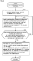
- Fig. 5 is a flowchart to illustrate the process of increasing air conditioning performance performed by controller 100.
- controller 100 changes the target value of temperature difference ⁇ T from ⁇ Ts to ⁇ Ts+ ⁇ (step S11).
- An amount of correction for target value ⁇ Ts in this case is + ⁇ .
- controller 100 raises operation frequency fc of compressor 11 from f1 to f2 to thereby vary evaporation temperature Te, causing temperature difference ⁇ T to follow target value ⁇ Ts+ ⁇ .
- controller 100 further raises operation frequency fc of compressor 11 from f2 to f3 to thereby further vary evaporation temperature Te, causing temperature difference ⁇ T to follow target value ⁇ Ts+ ⁇ (step S12).
- a maximum value of an amount of correction for evaporation temperature Te in this case is set to ⁇ 1 (in the case of cooling).
- Maximum value ⁇ 1 is set such that evaporation temperature Te after the correction does not fall below the freezing temperature 0°C of water.
- a maximum value of an amount of correction for condensation temperature Tc is set to ⁇ 2.
- step S13 operation frequency fc of compressor 11 is raised in a stepwise manner if temperature difference ⁇ T has not reached target value ⁇ Ts+ ⁇ after a lapse of a certain period of time. This is repeated until a canceling condition (step S13) is met.
- the canceling condition is met when at least one of the indoor units is stopped with a remote controller or the like, or when indoor temperature Tr reaches set temperature Trs (thermo-off state).
- indoor temperature Tr reaches set temperature Trs to satisfy the canceling condition (YES in S13).
- controller 100 sets amount of correction ⁇ for the target value of temperature difference ⁇ T to zero, returns the target value to ⁇ Ts, sets amount of correction ⁇ for evaporation temperature Te to zero, returns the target value of evaporation temperature Te to Tes, and performs at least one of lowering of pump driving voltage Vp and lowering of operation frequency fc of compressor 11 (step S14). While both the process of lowering pump driving voltage Vp and the process of lowering operation frequency fc of compressor 11 are performed at time t4 in the waveform diagram of Fig. 4 , either one of the processes may be performed.
- step S15 the process returns to the main routine in step S15, and it is determined again whether the performance-increasing control or the normal control should be performed by the process shown in the flowchart of Fig. 3 .
- Air conditioning apparatus 1 shown in Fig. 1 includes: compressor 11 for compressing the first heat medium (refrigerant); first heat exchanger 13 for exchanging heat between the first heat medium and outdoor air; second heat exchanger 22 for exchanging heat between the first heat medium and the second heat medium (water or brine); the plurality of third heat exchangers 31, 41 and 51 for exchanging heat between the second heat medium and indoor air; the plurality of flow rate control valves 33, 43 and 53 for controlling the flow rates of the second heat medium flowing respectively in the plurality of third heat exchangers 31, 41 and 51; and pump 23 for circulating the second heat medium between the plurality of third heat exchangers 31, 41, 51 and second heat exchanger 22.
- compressor 11 for compressing the first heat medium (refrigerant); first heat exchanger 13 for exchanging heat between the first heat medium and outdoor air; second heat exchanger 22 for exchanging heat between the first heat medium and the second heat medium (water or brine); the plurality of third heat exchangers 31, 41 and 51 for exchanging heat between the second heat medium and indoor
- the performance of a heat source or a cold source is increased or decreased as needed when the pump has an insufficient capacity, so that the heating and/or cooling performance can be kept within an appropriate range.
- air conditioning apparatus 1 further includes: the plurality of first temperature sensors 34, 44 and 54 for detecting the temperatures of the second heat medium flowing respectively into the plurality of third heat exchangers 31, 41 and 51; the plurality of second temperature sensors 35, 45 and 55 for detecting the temperatures of the second heat medium flowing respectively out of the plurality of third heat exchangers 31, 41 and 51; and controller 100 for controlling pump 23 and compressor 11.
- the indoor temperature can be smoothly guided to match the set temperature, while excessive increase in performance such as increase or decrease in indoor temperature past the set temperature is prevented.
- the first heat medium is refrigerant
- the second heat medium is water.
- Target temperature Tes when maximum value ⁇ 1 of correction width shown in the range between times t2 and t4 in Fig. 4 is applied is set to be higher than the freezing temperature of water (0°C). That is, controller 100 controls operation frequency fc of compressor 11 to such an extent that evaporation temperature Te of the refrigerant in the second heat exchanger does not fall below the freezing temperature of water (0°C). As a result, the performance of the heat source apparatus can be enhanced to such an extent that the second heat medium does not freeze.
- 1 air conditioning apparatus 1 air conditioning apparatus; 2 heat source apparatus; 3 indoor air conditioning device; 4, 5, 6, 7 pipe; 10 outdoor unit; 11 compressor; 12 four-way valve; 13 first heat exchanger; 15, 27, 36 control unit; 20 relay unit; 22 second heat exchanger; 23 pump; 24 expansion valve; 25 pressure sensor; 30, 40, 50 indoor unit; 31, 41, 51 third heat exchanger; 32, 42, 52 indoor fan; 33, 43, 53 flow rate control valve; 34, 35, 44, 45, 54, 55 temperature sensor; 100 controller.
Landscapes
- Engineering & Computer Science (AREA)
- Mechanical Engineering (AREA)
- General Engineering & Computer Science (AREA)
- Chemical & Material Sciences (AREA)
- Combustion & Propulsion (AREA)
- Physics & Mathematics (AREA)
- Thermal Sciences (AREA)
- Life Sciences & Earth Sciences (AREA)
- Sustainable Development (AREA)
- Air Conditioning Control Device (AREA)
- Other Air-Conditioning Systems (AREA)
Abstract
Description
- The present invention relates to a controller of an air conditioning system, an outdoor unit, a relay unit, a heat source apparatus, and an air conditioning system, and more specifically to a controller of an air conditioning system using a first heat medium and a second heat medium, an outdoor unit, a relay unit, a heat source apparatus, and an air conditioning system.
- Conventionally, an indirect air conditioning apparatus is known that generates hot and/or chilled water by a heat source apparatus such as a heat pump, and delivers the water to an indoor unit through a water pump and a pipe to perform heating and/or cooling in the interior of a room.
- Japanese Patent No.
5188572 - PTL 1: Japanese Patent No.
5188572 - In an indirect air conditioning apparatus such as described above, the length of, and the number of bent portions of, a water pipe between an indoor unit and a relay unit vary with the arrangement of the indoor unit and the relay unit, resulting in various resistances to water flow in the pipe as well. It is thus difficult to determine the capacity of a water pump. While it is preferred to install a water pump having a sufficient capacity, it is conceivable that a water pump having a smaller capacity than is required may be installed. An insufficient capacity of the water pump may result in insufficient heating and/or cooling performance.
- The present invention has been made to solve the problem described above, and has an object to provide a controller of an air conditioning system capable of keeping heating and/or cooling performance within an appropriate range, an outdoor unit, a relay unit, a heat source apparatus, and an air conditioning system, in an indirect air conditioner using water or brine.
- The present disclosure relates to a controller of an air conditioning system. The air conditioning system includes: a compressor configured to compress a first heat medium; a first heat exchanger configured to exchange heat between the first heat medium and outdoor air; a second heat exchanger configured to exchange heat between the first heat medium and a second heat medium; a plurality of third heat exchangers configured to exchange heat between the second heat medium and indoor air; a plurality of flow rate control valves configured to control flow rates of the second heat medium flowing respectively in the plurality of third heat exchangers; and a pump configured to circulate the second heat medium between the plurality of third heat exchangers and the second heat exchanger. When a state in which a driving voltage of the pump is set to an upper limit voltage and an opening degree of at least one of the plurality of flow rate control valves is set to a maximum opening degree continues for a first determination time period, the controller that controls the air conditioning system is configured to raise an operation frequency of the compressor at a first time so as to increase an amount of heat exchange by the second heat exchanger. When an operation stop request is input, or an indoor temperature reaches a set temperature, in at least one of the plurality of third heat exchangers after the first time, the controller is configured to lower the operation frequency of the compressor or lower the driving voltage of the pump.
- In another aspect, the present disclosure relates to an outdoor unit, including the compressor, the first heat exchanger, and the controller.
- In yet another aspect, the present disclosure relates to a relay unit, including the second heat exchanger, the pump, and the controller.
- In yet another aspect, the present disclosure relates to a heat source apparatus, including the compressor, the first heat exchanger, the second heat exchanger, the pump, and the controller.
- In yet another aspect, the present disclosure relates to an air conditioning system, including: a first heat medium circuit formed by the compressor, the first heat exchanger and the second heat exchanger; a second heat medium circuit formed by the pump, the second heat exchanger and the plurality of third heat exchangers; and the controller.
- According to the air conditioning apparatus, the heat source apparatus and the controller of the present disclosure, performance of a heat source or a cold source is increased or decreased as needed when a pump has an insufficient capacity, so that the heating and/or cooling performance can be kept within an appropriate range.
-
-
Fig. 1 shows the configuration of an air conditioning apparatus according to a first embodiment. -
Fig. 2 shows relation between an amount of water circulation and a differential pressure. -
Fig. 3 is a flowchart to illustrate a determination process performed by acontroller 100. -
Fig. 4 is an operation waveform diagram showing one example where a process of increasing air conditioning performance is performed. -
Fig. 5 is a flowchart to illustrate the process of increasing air conditioning performance performed bycontroller 100. - In the following, embodiments of the present invention will be described in detail with reference to the drawings. While a plurality of embodiments are described below, it has been intended from the time of filing of the present application to appropriately combine configurations described in the respective embodiments. Note that the same or corresponding parts are designated by the same characters in the drawings and will not be described repeatedly.
-
Fig. 1 shows the configuration of an air conditioning apparatus according to a first embodiment. Referring toFig. 1 , anair conditioning apparatus 1 includes aheat source apparatus 2, an indoorair conditioning device 3, and acontroller 100.Heat source apparatus 2 includes anoutdoor unit 10 and arelay unit 20. In the following description, a first heat medium can be exemplified by refrigerant, and a second heat medium can be exemplified by water or brine. -
Outdoor unit 10 includes part of a refrigeration cycle that operates as a heat source or a cold source for the first heat medium.Outdoor unit 10 includes acompressor 11, a four-way valve 12, and afirst heat exchanger 13.Fig. 1 shows an example where four-way valve 12 performs cooling, withheat source apparatus 2 serving as a cold source. When four-way valve 12 is switched to reverse the direction of circulation of the refrigerant, heating is performed, withheat source apparatus 2 serving as a heat source. -
Relay unit 20 includes asecond heat exchanger 22, apump 23 for circulating the second heat medium between indoorair conditioning device 3 and the outdoor unit, anexpansion valve 24, and apressure sensor 25 for detecting a differential pressure ΔP before and afterpump 23. Second heat exchanger 22 exchanges heat between the first heat medium and the second heat medium. A plate heat exchanger can be used assecond heat exchanger 22. -
Outdoor unit 10 andrelay unit 20 are connected to each other bypipes 4 and 5 for flowing the first heat medium.Compressor 11, four-way valve 12,first heat exchanger 13,expansion valve 24, andsecond heat exchanger 22 form a first heat medium circuit using the first heat medium. Note thatoutdoor unit 10 andrelay unit 20 may be integrated together inheat source apparatus 2. If they are integrated together,pipes 4 and 5 are accommodated in a casing. - Indoor
air conditioning device 3 andrelay unit 20 are connected to each other bypipes 6 and 7 for flowing the second heat medium. Indoorair conditioning device 3 includes anindoor unit 30, anindoor unit 40 and anindoor unit 50.Indoor units pipe 7.Pump 23,second heat exchanger 22, and parallel-connectedthird heat exchanger 31,third heat exchanger 41 andthird heat exchanger 51 which will be described later form a second heat medium circuit using the second heat medium. -
Indoor unit 30 includesthird heat exchanger 31, anindoor fan 32 for delivering indoor air tothird heat exchanger 31, a flowrate control valve 33 for controlling a flow rate of the second heat medium, andtemperature sensors Temperature sensor 34 measures a temperature of the second heat medium at an inlet side ofthird heat exchanger 31.Temperature sensor 35 measures a temperature of the second heat medium at an outlet side ofthird heat exchanger 31. -
Indoor unit 40 includesthird heat exchanger 41, anindoor fan 42 for delivering indoor air tothird heat exchanger 41, a flowrate control valve 43 for controlling a flow rate of the second heat medium, andtemperature sensors Temperature sensor 44 measures a temperature of the second heat medium at an inlet side ofthird heat exchanger 41.Temperature sensor 45 measures a temperature of the second heat medium at an outlet side ofthird heat exchanger 41. -
Indoor unit 50 includesthird heat exchanger 51, anindoor fan 52 for delivering indoor air tothird heat exchanger 51, a flowrate control valve 53 for controlling a flow rate of the second heat medium, andtemperature sensors Temperature sensor 54 measures a temperature of the second heat medium at an inlet side ofthird heat exchanger 51.Temperature sensor 55 measures a temperature of the second heat medium at an outlet side ofthird heat exchanger 51. -
Control units outdoor unit 10,relay unit 20 and indoorair conditioning device 3 cooperate with one another to operate ascontroller 100.Controller 100 controlscompressor 11,expansion valve 24, pump 23, flowrate control valves indoor fans pressure sensor 25 andtemperature sensors - Note that one of
control units control compressor 11,expansion valve 24, pump 23, flowrate control valves indoor fans other control units heat source apparatus 2 hasoutdoor unit 10 andrelay unit 20 that are integrated together,control units control unit 36. - In such indirect (water air conditioning)
air conditioning apparatus 1 using two types of heat media, performance ofpump 23 needs to be appropriately selected in accordance with the number of indoor units, and the length and path ofpipes 6 and 7. It is difficult, however, to correctly identify the length of, and the bent portions of, a pipe to be connected, and to identify pump performance. Accordingly, a pump lower in performance than is appropriate may be installed at the time of construction, resulting in insufficient air conditioning performance at a site of installation. - For this reason, when an amount of water delivered by
pump 23 is at a maximum value and indoor air conditioning performance is not satisfying required performance,controller 100 varies the temperature of the second heat medium (water or brine) at theheat source apparatus 2 side, to thereby avoid the insufficient performance at the site of installation. - Specifically, when at least one of flow
rate control valves pump 23 is at its maximum, if an inlet/outlet water temperature difference ΔT in the indoor heat exchanger corresponding to the fully open flow rate control valve maintains a value higher than a target value (= a state in which the performance cannot be ensured even with the pump at its maximum),controller 100 lowers an evaporation temperature Te at the heat source apparatus side (raises a condensation temperature Tc in the case of heating) to increase temperature difference ΔT, to thereby enhance the reduced indoor air conditioning performance. Note that ΔT = |T1-T2|, or |T3-T4|, or |T5-T6| holds inFig. 1 , where T1 to T6 represent the temperatures of the second heat medium detected bytemperature sensors - Here, indoor air conditioning performance Q is expressed by: Q = m×Cp×ΔT, where m represents an amount of circulation of the second heat medium, and Cp represents a specific heat of the second heat medium.
-
Fig. 2 shows relation between an amount of water circulation and a differential pressure. Each curve shown inFig. 2 represents a head characteristic ofpump 23, and the head characteristic is known in advance for each driving voltage ofpump 23.Controller 100 calculates amount m of water circulation based on differential pressure ΔP before and afterpump 23, a pump driving voltage Vp, and the pump head characteristic shown inFig. 2 . When amount m of water circulation is lower than a proper flow rate,controller 100 increases an amount of heat exchange bysecond heat exchanger 22 ofheat source apparatus 2 to raise ΔT, thereby ensuring indoor air conditioning performance Q. -
Fig. 3 is a flowchart to illustrate a determination process performed bycontroller 100. The process of this flowchart is invoked from a main routine of air conditioning control and performed at regular intervals or whenever a determination condition is met. Referring toFig. 3 , first, in step S1,controller 100 determines whether or notcompressor 11 is operating. Whencompressor 11 is not operating, in step S8,controller 100 returns the process to the main routine. - When
compressor 11 is operating (ON state) in step S1, the process proceeds to step S2. In step S2,controller 100 determines whether or not at least one of flowrate control valves - When one of flow
rate control valves pump 23 has risen to an upper limit voltage Vu. - When driving voltage Vp of
pump 23 has risen to upper limit voltage Vu in step S3, the process proceeds to step S4. In step S4,controller 100 determines whether or not temperature difference ΔT in one ofindoor heat exchangers rate control valves - When temperature difference ΔT has a value higher than the target value in step S4, the process proceeds to step S5. In step S5, it is determined whether or not indoor air conditioning performance Q calculated from current temperature difference ΔT and amount m of water circulation is insufficient with respect to target performance Qx.
- When indoor air conditioning performance Q is insufficient with respect to target performance Qx in step S5, control to increase the air conditioning performance is performed in step S7. The details of this control will be described with reference to
Figs. 4 and5 . - When any one of the conditions in steps S2 to S5 is not met (NO in any one of S2 to S5), on the other hand, the process proceeds to step S6, where normal control is performed. In the normal control, an operation frequency of
compressor 11 is adjusted such that evaporation temperature Te reaches a target temperature in the case of cooling, and the operation frequency ofcompressor 11 is adjusted such that condensation temperature Tc reaches a target temperature in the case of heating. -
Fig. 4 is an operation waveform diagram showing one example where a process of increasing air conditioning performance is performed.Fig. 4 shows, from the top to the bottom: indoor temperature Tr [°C] and set temperature Trs [°C]; inlet/outlet temperature difference ΔT [°C] and temperature difference target value ΔTs [°C] of the indoor unit; operation frequency fc [Hz] of the compressor; evaporation temperature Te [°C] and evaporation temperature target value Tes [°C] of the first heat medium; pump driving voltage Vp [V]; and flow rate control valve opening degree D. - This waveform diagram shows an example where cooling operation is being performed. Between times t0 and t1, normal control is performed, with operation frequency fc of
compressor 11 being set to a frequency f1.Expansion valve 24 is controlled such that evaporation temperature Te infirst heat exchanger 13 matches target value Tes. Since indoor temperature Tr is higher than set temperature Trs, the cooling performance of the indoor unit is increased. In this case, an actual measured value ΔT calculated from the temperatures measured bytemperature sensors - When at least one of the plurality of third heat exchangers is insufficient in air conditioning performance (Tr > Trs) in this manner, if opening degree D of the flow rate control valve corresponding to the third heat exchanger insufficient in air conditioning performance is smaller than a maximum opening degree Du, or if driving voltage Vp of the pump is lower than upper limit voltage Vu,
controller 100 performs control to raise driving voltage Vp of the pump or to increase opening degree D of the corresponding flow rate control valve, so as to increase the flow rate of the second heat medium flowing in the third heat exchanger insufficient in air conditioning performance. Accordingly, between times t0 and t1, opening degree D of flowrate control valve 33 and the driving voltage ofpump 23 are increased in a stepwise manner, to enhance the cooling performance of the indoor unit. - At time t1, opening degree D of flow
rate control valve 33 reaches maximum opening degree Du, and driving voltage Vp ofpump 23 reaches upper limit voltage Vu, and thus the flow rate of the second heat medium to the indoor unit can no longer be increased. - Between times t1 and t2, a state continues in which indoor temperature Tr does not decrease to set temperature Trs, although opening degree D is maximum opening degree Du and driving voltage Vp of
pump 23 is upper limit voltage Vu. - At time t2, in response to a lapse of a first determination time period TP1 in such a state,
controller 100 starts performance-increasing control. -
Fig. 5 is a flowchart to illustrate the process of increasing air conditioning performance performed bycontroller 100. Referring toFigs. 4 and5 , when the performance-increasing control is started at time t2,controller 100 changes the target value of temperature difference ΔT from ΔTs to ΔTs+α (step S11). An amount of correction for target value ΔTs in this case is +α. As a result, the actual measured value of temperature difference ΔT becomes lower than target value ΔTs+α. In response,controller 100 raises operation frequency fc ofcompressor 11 from f1 to f2 to thereby vary evaporation temperature Te, causing temperature difference ΔT to follow target value ΔTs+α. - At time t3 when a second determination time period TP2 elapses in this state, temperature difference ΔT has not yet been able to follow target value ΔTs+α. Therefore,
controller 100 further raises operation frequency fc ofcompressor 11 from f2 to f3 to thereby further vary evaporation temperature Te, causing temperature difference ΔT to follow target value ΔTs+α (step S12). - Note that a maximum value of an amount of correction for evaporation temperature Te in this case is set to β1 (in the case of cooling). Maximum value β1 is set such that evaporation temperature Te after the correction does not fall below the freezing temperature 0°C of water. In the case of heating, a maximum value of an amount of correction for condensation temperature Tc is set to β2.
- In this manner, operation frequency fc of
compressor 11 is raised in a stepwise manner if temperature difference ΔT has not reached target value ΔTs+α after a lapse of a certain period of time. This is repeated until a canceling condition (step S13) is met. The canceling condition is met when at least one of the indoor units is stopped with a remote controller or the like, or when indoor temperature Tr reaches set temperature Trs (thermo-off state). - In the present embodiment, at time t4, indoor temperature Tr reaches set temperature Trs to satisfy the canceling condition (YES in S13). As a result,
controller 100 sets amount of correction α for the target value of temperature difference ΔT to zero, returns the target value to ΔTs, sets amount of correction β for evaporation temperature Te to zero, returns the target value of evaporation temperature Te to Tes, and performs at least one of lowering of pump driving voltage Vp and lowering of operation frequency fc of compressor 11 (step S14). While both the process of lowering pump driving voltage Vp and the process of lowering operation frequency fc ofcompressor 11 are performed at time t4 in the waveform diagram ofFig. 4 , either one of the processes may be performed. - Then, the process returns to the main routine in step S15, and it is determined again whether the performance-increasing control or the normal control should be performed by the process shown in the flowchart of
Fig. 3 . - Referring again to
Fig. 1 , the air conditioning apparatus in the present embodiment described above is summarized.Air conditioning apparatus 1 shown inFig. 1 includes:compressor 11 for compressing the first heat medium (refrigerant);first heat exchanger 13 for exchanging heat between the first heat medium and outdoor air;second heat exchanger 22 for exchanging heat between the first heat medium and the second heat medium (water or brine); the plurality ofthird heat exchangers rate control valves third heat exchangers third heat exchangers second heat exchanger 22. - As shown in
Fig. 4 , when a state in which driving voltage Vp ofpump 23 is set to upper limit voltage Vu and opening degree D of at least one of the plurality of flowrate control valves compressor 11 is raised from f1 to f2 at a first time (t2) so as to increase the amount of heat exchange bysecond heat exchanger 22. When indoor temperature Tr reaches set temperature Trs in at least one of the plurality ofthird heat exchangers compressor 11 is lowered from f3 to f1, and driving voltage Vp ofpump 23 is lowered. Note that only one of operation frequency fc and driving voltage Vp ofpump 23 may be lowered at time t4. In addition, this process may be performed when an operation stop request is input, instead of when indoor temperature Tr reaches set temperature Trs. - In this manner, the performance of a heat source or a cold source is increased or decreased as needed when the pump has an insufficient capacity, so that the heating and/or cooling performance can be kept within an appropriate range.
- Preferably,
air conditioning apparatus 1 further includes: the plurality offirst temperature sensors third heat exchangers second temperature sensors third heat exchangers controller 100 for controllingpump 23 andcompressor 11. - When a state in which driving voltage Vp of
pump 23 is set to upper limit voltage Vu and opening degree D of at least one of the plurality of flowrate control valves Fig. 4 ,controller 100 raises operation frequency fc ofcompressor 11 by a first amount of increase Δf1 (= f2-f1) at the first time (t2) so as to increase the amount of heat exchange bysecond heat exchanger 22, and when difference ΔT between the temperatures detected by the first temperature sensor and the second temperature sensor is still smaller than target value ΔTs after a lapse of second determination time period TP2 since the first time (t2),controller 100 further raises operation frequency fc ofcompressor 11 by a second amount of increase Δf2 (= f3-f2) at time t3. - By enhancing the performance of the heat source apparatus in a stepwise manner as described above, the indoor temperature can be smoothly guided to match the set temperature, while excessive increase in performance such as increase or decrease in indoor temperature past the set temperature is prevented.
- Preferably, the first heat medium is refrigerant, and the second heat medium is water. Target temperature Tes when maximum value β1 of correction width shown in the range between times t2 and t4 in
Fig. 4 is applied is set to be higher than the freezing temperature of water (0°C). That is,controller 100 controls operation frequency fc ofcompressor 11 to such an extent that evaporation temperature Te of the refrigerant in the second heat exchanger does not fall below the freezing temperature of water (0°C). As a result, the performance of the heat source apparatus can be enhanced to such an extent that the second heat medium does not freeze. - It should be understood that the embodiments disclosed herein are illustrative and non-restrictive in every respect. The scope of the present invention is defined by the terms of the claims, rather than the description of the embodiments above, and is intended to include any modifications within the meaning and scope equivalent to the terms of the claims.
- 1 air conditioning apparatus; 2 heat source apparatus; 3 indoor air conditioning device; 4, 5, 6, 7 pipe; 10 outdoor unit; 11 compressor; 12 four-way valve; 13 first heat exchanger; 15, 27, 36 control unit; 20 relay unit; 22 second heat exchanger; 23 pump; 24 expansion valve; 25 pressure sensor; 30, 40, 50 indoor unit; 31, 41, 51 third heat exchanger; 32, 42, 52 indoor fan; 33, 43, 53 flow rate control valve; 34, 35, 44, 45, 54, 55 temperature sensor; 100 controller.
Claims (8)
- A controller that controls an air conditioning system, the air conditioning system comprising:a compressor configured to compress a first heat medium;a first heat exchanger configured to exchange heat between the first heat medium and outdoor air;a second heat exchanger configured to exchange heat between the first heat medium and a second heat medium;a plurality of third heat exchangers configured to exchange heat between the second heat medium and indoor air;a plurality of flow rate control valves configured to control flow rates of the second heat medium flowing respectively in the plurality of third heat exchangers; anda pump configured to circulate the second heat medium between the plurality of third heat exchangers and the second heat exchanger,when a state in which a driving voltage of the pump is set to an upper limit voltage and an opening degree of at least one of the plurality of flow rate control valves is set to a maximum opening degree continues for a first determination time period, the controller being configured to raise an operation frequency of the compressor at a first time so as to increase an amount of heat exchange by the second heat exchanger, andwhen an operation stop request is input, or an indoor temperature reaches a set temperature, in at least one of the plurality of third heat exchangers after the first time, the controller being configured to lower the operation frequency of the compressor or lower the driving voltage of the pump.
- The controller according to claim 1, wherein
the air conditioning system further comprises
a plurality of first temperature sensors configured to detect temperatures of the second heat medium flowing respectively into the plurality of third heat exchangers, and
a plurality of second temperature sensors configured to detect temperatures of the second heat medium flowing respectively out of the plurality of third heat exchangers,
the controller is configured to control the pump and the compressor, and
when the state in which the driving voltage of the pump is set to the upper limit voltage, and the opening degree of at least one of the plurality of flow rate control valves is set to the maximum opening degree continues for the first determination time period, the controller is configured to raise the operation frequency of the compressor by a first amount of increase at the first time so as to increase the amount of heat exchange by the second heat exchanger, and
when a difference between the temperatures detected by the first temperature sensor and the second temperature sensor corresponding to the third heat exchanger provided with the flow rate control valve set to the maximum opening degree is still smaller than a target value after a lapse of a second determination time period since the first time, the controller is configured to further raise the operation frequency of the compressor by a second amount of increase. - The controller according to claim 2, wherein
the first heat medium is refrigerant,
the second heat medium is water, and
the controller is configured to control the operation frequency of the compressor to such an extent that an evaporation temperature of the refrigerant in the second heat exchanger does not fall below a freezing temperature of the water. - The controller according to any one of claims 1 to 3, wherein
when at least one of the plurality of third heat exchangers is insufficient in air conditioning performance, if the opening degree of the flow rate control valve corresponding to the third heat exchanger insufficient in air conditioning performance is smaller than the maximum opening degree, or if the driving voltage of the pump is lower than the upper limit voltage, the controller is configured to raise the driving voltage of the pump or increase the opening degree of the corresponding flow rate control valve, so as to increase the flow rate of the second heat medium flowing in the third heat exchanger insufficient in air conditioning performance. - An outdoor unit, comprising the compressor, the first heat exchanger, and the controller according to any one of claims 1 to 4.
- A relay unit, comprising the second heat exchanger, the pump, and the controller according to any one of claims 1 to 4.
- A heat source apparatus, comprising the compressor, the first heat exchanger, the second heat exchanger, the pump, and the controller according to any one of claims 1 to 4.
- An air conditioning system, comprising:a first heat medium circuit formed by the compressor, the first heat exchanger and the second heat exchanger;a second heat medium circuit formed by the pump, the second heat exchanger and the plurality of third heat exchangers; andthe controller according to any one of claims 1 to 4.
Applications Claiming Priority (1)
| Application Number | Priority Date | Filing Date | Title |
|---|---|---|---|
| PCT/JP2018/014426 WO2019193685A1 (en) | 2018-04-04 | 2018-04-04 | Air conditioning system control device, outdoor unit, relay unit, heat source unit, and air conditioning system |
Publications (3)
| Publication Number | Publication Date |
|---|---|
| EP3779323A1 true EP3779323A1 (en) | 2021-02-17 |
| EP3779323A4 EP3779323A4 (en) | 2021-03-17 |
| EP3779323B1 EP3779323B1 (en) | 2023-02-22 |
Family
ID=68100655
Family Applications (1)
| Application Number | Title | Priority Date | Filing Date |
|---|---|---|---|
| EP18913342.4A Active EP3779323B1 (en) | 2018-04-04 | 2018-04-04 | Air conditioning system control device, outdoor unit, relay unit, heat source unit, and air conditioning system |
Country Status (4)
| Country | Link |
|---|---|
| US (1) | US11333388B2 (en) |
| EP (1) | EP3779323B1 (en) |
| JP (1) | JP6896161B2 (en) |
| WO (1) | WO2019193685A1 (en) |
Families Citing this family (7)
| Publication number | Priority date | Publication date | Assignee | Title |
|---|---|---|---|---|
| JP7134265B2 (en) * | 2019-02-05 | 2022-09-09 | 三菱電機株式会社 | Control devices for air conditioners, outdoor units, repeaters, heat source units, and air conditioners |
| CN114110993B (en) * | 2020-08-25 | 2023-04-25 | 广东美的制冷设备有限公司 | Throttle control method, device, storage medium and apparatus for air conditioning system |
| CN113339943B (en) * | 2021-05-10 | 2023-01-20 | 广东Tcl智能暖通设备有限公司 | Air conditioner control method, air conditioner control device, air conditioner system and computer readable storage medium |
| EP4227605A1 (en) * | 2022-02-11 | 2023-08-16 | Daikin Europe N.V. | Refrigeration device |
| CN114543172B (en) * | 2022-02-23 | 2023-08-08 | 青岛海信日立空调系统有限公司 | Air conditioner |
| CN116951608B (en) * | 2023-08-07 | 2026-04-17 | 珠海格力电器股份有限公司 | A control method for an air conditioning heating system |
| DE102024210088A1 (en) * | 2024-10-18 | 2026-04-23 | Robert Bosch Gesellschaft mit beschränkter Haftung | Heat pump system and operating procedure |
Family Cites Families (10)
| Publication number | Priority date | Publication date | Assignee | Title |
|---|---|---|---|---|
| JP4651551B2 (en) | 2006-01-31 | 2011-03-16 | 東京電力株式会社 | Air conditioning system |
| JP4693645B2 (en) | 2006-01-31 | 2011-06-01 | 東京電力株式会社 | Air conditioning system |
| JP5188572B2 (en) | 2008-04-30 | 2013-04-24 | 三菱電機株式会社 | Air conditioner |
| US8752397B2 (en) * | 2008-10-29 | 2014-06-17 | Mitsubishi Electric Corporation | Air-conditioning apparatus |
| ES2734149T3 (en) * | 2009-10-27 | 2019-12-04 | Mitsubishi Electric Corp | Air conditioning device |
| JP5511578B2 (en) * | 2010-08-06 | 2014-06-04 | 三菱重工業株式会社 | Refrigerator control device |
| JP5747159B2 (en) * | 2011-06-14 | 2015-07-08 | パナソニックIpマネジメント株式会社 | Heat pump hot water heater |
| JP5484503B2 (en) * | 2012-03-14 | 2014-05-07 | 三菱電機株式会社 | Cooling system |
| JP5898537B2 (en) * | 2012-03-19 | 2016-04-06 | サンデンホールディングス株式会社 | Heat pump heating system |
| PL3076110T3 (en) * | 2015-03-30 | 2019-08-30 | Viessmann Werke Gmbh & Co. Kg | Fluid system and method for controlling a fluid system |
-
2018
- 2018-04-04 JP JP2020512159A patent/JP6896161B2/en not_active Expired - Fee Related
- 2018-04-04 WO PCT/JP2018/014426 patent/WO2019193685A1/en not_active Ceased
- 2018-04-04 US US16/976,310 patent/US11333388B2/en active Active
- 2018-04-04 EP EP18913342.4A patent/EP3779323B1/en active Active
Also Published As
| Publication number | Publication date |
|---|---|
| US20210041128A1 (en) | 2021-02-11 |
| EP3779323A4 (en) | 2021-03-17 |
| WO2019193685A1 (en) | 2019-10-10 |
| EP3779323B1 (en) | 2023-02-22 |
| JP6896161B2 (en) | 2021-06-30 |
| US11333388B2 (en) | 2022-05-17 |
| JPWO2019193685A1 (en) | 2021-02-25 |
Similar Documents
| Publication | Publication Date | Title |
|---|---|---|
| EP3779323B1 (en) | Air conditioning system control device, outdoor unit, relay unit, heat source unit, and air conditioning system | |
| JP6257801B2 (en) | Refrigeration cycle apparatus and refrigeration cycle apparatus abnormality detection system | |
| EP2677251B1 (en) | Refrigeration cycle device and refrigeration cycle control method | |
| CN102770718B (en) | Air-conditioning system and control method of the air-conditioning system | |
| KR101547355B1 (en) | Control method of air conditioner and air conditioner | |
| JP6184503B2 (en) | Oil level detection device and refrigeration air conditioner equipped with the oil level detection device | |
| JP6950191B2 (en) | Air conditioner | |
| EP2716989A1 (en) | Temperature adjusting system, air conditioning system, and control method | |
| JP5094801B2 (en) | Refrigeration cycle apparatus and air conditioner | |
| AU2012317517B2 (en) | Refrigeration system | |
| JP2010249452A (en) | Air conditioner | |
| KR20100007531A (en) | Air conditioner and method of controlling the same | |
| JP2012141113A (en) | Air conditioning/water heating device system | |
| EP2672204A1 (en) | Binary refrigeration cycle device | |
| CN107208938A (en) | Air-conditioning device | |
| US11913694B2 (en) | Heat pump system | |
| KR20100036786A (en) | Air conditioner and control method of the same | |
| KR20100048194A (en) | Air conditioner and operating method thereof | |
| US11408656B2 (en) | Heat source device and refrigeration cycle device | |
| JP2010007997A (en) | Refrigerant amount determining method of air conditioning device, and air conditioning device | |
| EP3779309B1 (en) | Air conditioning system control device, outdoor unit, relay device, heat source device, and air conditioning system | |
| US20150292752A1 (en) | Heat pump with improved performance during cold outdoor temperatures | |
| KR20090107310A (en) | Multi type air conditioner and its heating operation cooperative control method | |
| KR101227477B1 (en) | Air conditioner having volume variableness type condenser and method of control thereof | |
| CN120385140A (en) | Control method for air conditioner, computer readable storage medium, and air conditioner |
Legal Events
| Date | Code | Title | Description |
|---|---|---|---|
| STAA | Information on the status of an ep patent application or granted ep patent |
Free format text: STATUS: THE INTERNATIONAL PUBLICATION HAS BEEN MADE |
|
| PUAI | Public reference made under article 153(3) epc to a published international application that has entered the european phase |
Free format text: ORIGINAL CODE: 0009012 |
|
| STAA | Information on the status of an ep patent application or granted ep patent |
Free format text: STATUS: REQUEST FOR EXAMINATION WAS MADE |
|
| 17P | Request for examination filed |
Effective date: 20200925 |
|
| AK | Designated contracting states |
Kind code of ref document: A1 Designated state(s): AL AT BE BG CH CY CZ DE DK EE ES FI FR GB GR HR HU IE IS IT LI LT LU LV MC MK MT NL NO PL PT RO RS SE SI SK SM TR |
|
| AX | Request for extension of the european patent |
Extension state: BA ME |
|
| A4 | Supplementary search report drawn up and despatched |
Effective date: 20210215 |
|
| RIC1 | Information provided on ipc code assigned before grant |
Ipc: F24F 11/86 20180101ALI20210209BHEP Ipc: F25B 49/02 20060101ALI20210209BHEP Ipc: F25B 13/00 20060101ALN20210209BHEP Ipc: F25B 1/00 20060101AFI20210209BHEP Ipc: F24F 5/00 20060101ALI20210209BHEP Ipc: F25B 25/00 20060101ALI20210209BHEP Ipc: F24F 11/83 20180101ALI20210209BHEP |
|
| DAV | Request for validation of the european patent (deleted) | ||
| DAX | Request for extension of the european patent (deleted) | ||
| GRAP | Despatch of communication of intention to grant a patent |
Free format text: ORIGINAL CODE: EPIDOSNIGR1 |
|
| STAA | Information on the status of an ep patent application or granted ep patent |
Free format text: STATUS: GRANT OF PATENT IS INTENDED |
|
| RIC1 | Information provided on ipc code assigned before grant |
Ipc: F25B 13/00 20060101ALN20220928BHEP Ipc: F25B 49/02 20060101ALI20220928BHEP Ipc: F25B 25/00 20060101ALI20220928BHEP Ipc: F24F 11/86 20180101ALI20220928BHEP Ipc: F24F 11/83 20180101ALI20220928BHEP Ipc: F24F 5/00 20060101ALI20220928BHEP Ipc: F25B 1/00 20060101AFI20220928BHEP |
|
| INTG | Intention to grant announced |
Effective date: 20221024 |
|
| GRAS | Grant fee paid |
Free format text: ORIGINAL CODE: EPIDOSNIGR3 |
|
| GRAA | (expected) grant |
Free format text: ORIGINAL CODE: 0009210 |
|
| STAA | Information on the status of an ep patent application or granted ep patent |
Free format text: STATUS: THE PATENT HAS BEEN GRANTED |
|
| AK | Designated contracting states |
Kind code of ref document: B1 Designated state(s): AL AT BE BG CH CY CZ DE DK EE ES FI FR GB GR HR HU IE IS IT LI LT LU LV MC MK MT NL NO PL PT RO RS SE SI SK SM TR |
|
| REG | Reference to a national code |
Ref country code: GB Ref legal event code: FG4D |
|
| REG | Reference to a national code |
Ref country code: CH Ref legal event code: EP |
|
| REG | Reference to a national code |
Ref country code: AT Ref legal event code: REF Ref document number: 1549744 Country of ref document: AT Kind code of ref document: T Effective date: 20230315 Ref country code: IE Ref legal event code: FG4D |
|
| REG | Reference to a national code |
Ref country code: DE Ref legal event code: R096 Ref document number: 602018046569 Country of ref document: DE |
|
| REG | Reference to a national code |
Ref country code: LT Ref legal event code: MG9D |
|
| REG | Reference to a national code |
Ref country code: NL Ref legal event code: MP Effective date: 20230222 |
|
| REG | Reference to a national code |
Ref country code: AT Ref legal event code: MK05 Ref document number: 1549744 Country of ref document: AT Kind code of ref document: T Effective date: 20230222 |
|
| PG25 | Lapsed in a contracting state [announced via postgrant information from national office to epo] |
Ref country code: RS Free format text: LAPSE BECAUSE OF FAILURE TO SUBMIT A TRANSLATION OF THE DESCRIPTION OR TO PAY THE FEE WITHIN THE PRESCRIBED TIME-LIMIT Effective date: 20230222 Ref country code: PT Free format text: LAPSE BECAUSE OF FAILURE TO SUBMIT A TRANSLATION OF THE DESCRIPTION OR TO PAY THE FEE WITHIN THE PRESCRIBED TIME-LIMIT Effective date: 20230622 Ref country code: NO Free format text: LAPSE BECAUSE OF FAILURE TO SUBMIT A TRANSLATION OF THE DESCRIPTION OR TO PAY THE FEE WITHIN THE PRESCRIBED TIME-LIMIT Effective date: 20230522 Ref country code: NL Free format text: LAPSE BECAUSE OF FAILURE TO SUBMIT A TRANSLATION OF THE DESCRIPTION OR TO PAY THE FEE WITHIN THE PRESCRIBED TIME-LIMIT Effective date: 20230222 Ref country code: LV Free format text: LAPSE BECAUSE OF FAILURE TO SUBMIT A TRANSLATION OF THE DESCRIPTION OR TO PAY THE FEE WITHIN THE PRESCRIBED TIME-LIMIT Effective date: 20230222 Ref country code: LT Free format text: LAPSE BECAUSE OF FAILURE TO SUBMIT A TRANSLATION OF THE DESCRIPTION OR TO PAY THE FEE WITHIN THE PRESCRIBED TIME-LIMIT Effective date: 20230222 Ref country code: HR Free format text: LAPSE BECAUSE OF FAILURE TO SUBMIT A TRANSLATION OF THE DESCRIPTION OR TO PAY THE FEE WITHIN THE PRESCRIBED TIME-LIMIT Effective date: 20230222 Ref country code: ES Free format text: LAPSE BECAUSE OF FAILURE TO SUBMIT A TRANSLATION OF THE DESCRIPTION OR TO PAY THE FEE WITHIN THE PRESCRIBED TIME-LIMIT Effective date: 20230222 Ref country code: AT Free format text: LAPSE BECAUSE OF FAILURE TO SUBMIT A TRANSLATION OF THE DESCRIPTION OR TO PAY THE FEE WITHIN THE PRESCRIBED TIME-LIMIT Effective date: 20230222 |
|
| P01 | Opt-out of the competence of the unified patent court (upc) registered |
Effective date: 20230711 |
|
| PG25 | Lapsed in a contracting state [announced via postgrant information from national office to epo] |
Ref country code: SE Free format text: LAPSE BECAUSE OF FAILURE TO SUBMIT A TRANSLATION OF THE DESCRIPTION OR TO PAY THE FEE WITHIN THE PRESCRIBED TIME-LIMIT Effective date: 20230222 Ref country code: PL Free format text: LAPSE BECAUSE OF FAILURE TO SUBMIT A TRANSLATION OF THE DESCRIPTION OR TO PAY THE FEE WITHIN THE PRESCRIBED TIME-LIMIT Effective date: 20230222 Ref country code: IS Free format text: LAPSE BECAUSE OF FAILURE TO SUBMIT A TRANSLATION OF THE DESCRIPTION OR TO PAY THE FEE WITHIN THE PRESCRIBED TIME-LIMIT Effective date: 20230622 Ref country code: GR Free format text: LAPSE BECAUSE OF FAILURE TO SUBMIT A TRANSLATION OF THE DESCRIPTION OR TO PAY THE FEE WITHIN THE PRESCRIBED TIME-LIMIT Effective date: 20230523 Ref country code: FI Free format text: LAPSE BECAUSE OF FAILURE TO SUBMIT A TRANSLATION OF THE DESCRIPTION OR TO PAY THE FEE WITHIN THE PRESCRIBED TIME-LIMIT Effective date: 20230222 |
|
| PG25 | Lapsed in a contracting state [announced via postgrant information from national office to epo] |
Ref country code: SM Free format text: LAPSE BECAUSE OF FAILURE TO SUBMIT A TRANSLATION OF THE DESCRIPTION OR TO PAY THE FEE WITHIN THE PRESCRIBED TIME-LIMIT Effective date: 20230222 Ref country code: RO Free format text: LAPSE BECAUSE OF FAILURE TO SUBMIT A TRANSLATION OF THE DESCRIPTION OR TO PAY THE FEE WITHIN THE PRESCRIBED TIME-LIMIT Effective date: 20230222 Ref country code: EE Free format text: LAPSE BECAUSE OF FAILURE TO SUBMIT A TRANSLATION OF THE DESCRIPTION OR TO PAY THE FEE WITHIN THE PRESCRIBED TIME-LIMIT Effective date: 20230222 Ref country code: DK Free format text: LAPSE BECAUSE OF FAILURE TO SUBMIT A TRANSLATION OF THE DESCRIPTION OR TO PAY THE FEE WITHIN THE PRESCRIBED TIME-LIMIT Effective date: 20230222 Ref country code: CZ Free format text: LAPSE BECAUSE OF FAILURE TO SUBMIT A TRANSLATION OF THE DESCRIPTION OR TO PAY THE FEE WITHIN THE PRESCRIBED TIME-LIMIT Effective date: 20230222 |
|
| REG | Reference to a national code |
Ref country code: DE Ref legal event code: R097 Ref document number: 602018046569 Country of ref document: DE |
|
| PG25 | Lapsed in a contracting state [announced via postgrant information from national office to epo] |
Ref country code: SK Free format text: LAPSE BECAUSE OF FAILURE TO SUBMIT A TRANSLATION OF THE DESCRIPTION OR TO PAY THE FEE WITHIN THE PRESCRIBED TIME-LIMIT Effective date: 20230222 |
|
| REG | Reference to a national code |
Ref country code: CH Ref legal event code: PL |
|
| PG25 | Lapsed in a contracting state [announced via postgrant information from national office to epo] |
Ref country code: LU Free format text: LAPSE BECAUSE OF NON-PAYMENT OF DUE FEES Effective date: 20230404 |
|
| PLBE | No opposition filed within time limit |
Free format text: ORIGINAL CODE: 0009261 |
|
| STAA | Information on the status of an ep patent application or granted ep patent |
Free format text: STATUS: NO OPPOSITION FILED WITHIN TIME LIMIT |
|
| REG | Reference to a national code |
Ref country code: BE Ref legal event code: MM Effective date: 20230430 |
|
| PG25 | Lapsed in a contracting state [announced via postgrant information from national office to epo] |
Ref country code: MC Free format text: LAPSE BECAUSE OF FAILURE TO SUBMIT A TRANSLATION OF THE DESCRIPTION OR TO PAY THE FEE WITHIN THE PRESCRIBED TIME-LIMIT Effective date: 20230222 |
|
| GBPC | Gb: european patent ceased through non-payment of renewal fee |
Effective date: 20230522 |
|
| 26N | No opposition filed |
Effective date: 20231123 |
|
| PG25 | Lapsed in a contracting state [announced via postgrant information from national office to epo] |
Ref country code: SI Free format text: LAPSE BECAUSE OF FAILURE TO SUBMIT A TRANSLATION OF THE DESCRIPTION OR TO PAY THE FEE WITHIN THE PRESCRIBED TIME-LIMIT Effective date: 20230222 Ref country code: MC Free format text: LAPSE BECAUSE OF FAILURE TO SUBMIT A TRANSLATION OF THE DESCRIPTION OR TO PAY THE FEE WITHIN THE PRESCRIBED TIME-LIMIT Effective date: 20230222 Ref country code: LI Free format text: LAPSE BECAUSE OF NON-PAYMENT OF DUE FEES Effective date: 20230430 Ref country code: FR Free format text: LAPSE BECAUSE OF NON-PAYMENT OF DUE FEES Effective date: 20230422 Ref country code: CH Free format text: LAPSE BECAUSE OF NON-PAYMENT OF DUE FEES Effective date: 20230430 |
|
| REG | Reference to a national code |
Ref country code: IE Ref legal event code: MM4A |
|
| PG25 | Lapsed in a contracting state [announced via postgrant information from national office to epo] |
Ref country code: BE Free format text: LAPSE BECAUSE OF NON-PAYMENT OF DUE FEES Effective date: 20230430 |
|
| PG25 | Lapsed in a contracting state [announced via postgrant information from national office to epo] |
Ref country code: IE Free format text: LAPSE BECAUSE OF NON-PAYMENT OF DUE FEES Effective date: 20230404 |
|
| PG25 | Lapsed in a contracting state [announced via postgrant information from national office to epo] |
Ref country code: IE Free format text: LAPSE BECAUSE OF NON-PAYMENT OF DUE FEES Effective date: 20230404 Ref country code: GB Free format text: LAPSE BECAUSE OF NON-PAYMENT OF DUE FEES Effective date: 20230522 |
|
| PG25 | Lapsed in a contracting state [announced via postgrant information from national office to epo] |
Ref country code: IT Free format text: LAPSE BECAUSE OF FAILURE TO SUBMIT A TRANSLATION OF THE DESCRIPTION OR TO PAY THE FEE WITHIN THE PRESCRIBED TIME-LIMIT Effective date: 20230222 |
|
| PGFP | Annual fee paid to national office [announced via postgrant information from national office to epo] |
Ref country code: DE Payment date: 20240227 Year of fee payment: 7 |
|
| PG25 | Lapsed in a contracting state [announced via postgrant information from national office to epo] |
Ref country code: BG Free format text: LAPSE BECAUSE OF FAILURE TO SUBMIT A TRANSLATION OF THE DESCRIPTION OR TO PAY THE FEE WITHIN THE PRESCRIBED TIME-LIMIT Effective date: 20230222 |
|
| PG25 | Lapsed in a contracting state [announced via postgrant information from national office to epo] |
Ref country code: BG Free format text: LAPSE BECAUSE OF FAILURE TO SUBMIT A TRANSLATION OF THE DESCRIPTION OR TO PAY THE FEE WITHIN THE PRESCRIBED TIME-LIMIT Effective date: 20230222 |
|
| PG25 | Lapsed in a contracting state [announced via postgrant information from national office to epo] |
Ref country code: CY Free format text: LAPSE BECAUSE OF FAILURE TO SUBMIT A TRANSLATION OF THE DESCRIPTION OR TO PAY THE FEE WITHIN THE PRESCRIBED TIME-LIMIT; INVALID AB INITIO Effective date: 20180404 |
|
| PG25 | Lapsed in a contracting state [announced via postgrant information from national office to epo] |
Ref country code: HU Free format text: LAPSE BECAUSE OF FAILURE TO SUBMIT A TRANSLATION OF THE DESCRIPTION OR TO PAY THE FEE WITHIN THE PRESCRIBED TIME-LIMIT; INVALID AB INITIO Effective date: 20180404 |
|
| REG | Reference to a national code |
Ref country code: DE Ref legal event code: R119 Ref document number: 602018046569 Country of ref document: DE |
|
| PG25 | Lapsed in a contracting state [announced via postgrant information from national office to epo] |
Ref country code: TR Free format text: LAPSE BECAUSE OF FAILURE TO SUBMIT A TRANSLATION OF THE DESCRIPTION OR TO PAY THE FEE WITHIN THE PRESCRIBED TIME-LIMIT Effective date: 20230222 |
|
| PG25 | Lapsed in a contracting state [announced via postgrant information from national office to epo] |
Ref country code: DE Free format text: LAPSE BECAUSE OF NON-PAYMENT OF DUE FEES Effective date: 20251104 |