EP3779321A1 - Verfolgungsvorrichtung - Google Patents
Verfolgungsvorrichtung Download PDFInfo
- Publication number
- EP3779321A1 EP3779321A1 EP18914062.7A EP18914062A EP3779321A1 EP 3779321 A1 EP3779321 A1 EP 3779321A1 EP 18914062 A EP18914062 A EP 18914062A EP 3779321 A1 EP3779321 A1 EP 3779321A1
- Authority
- EP
- European Patent Office
- Prior art keywords
- radiation
- tracking device
- lens
- solar radiation
- absorbing side
- Prior art date
- Legal status (The legal status is an assumption and is not a legal conclusion. Google has not performed a legal analysis and makes no representation as to the accuracy of the status listed.)
- Granted
Links
Images




Classifications
-
- F—MECHANICAL ENGINEERING; LIGHTING; HEATING; WEAPONS; BLASTING
- F24—HEATING; RANGES; VENTILATING
- F24S—SOLAR HEAT COLLECTORS; SOLAR HEAT SYSTEMS
- F24S23/00—Arrangements for concentrating solar-rays for solar heat collectors
- F24S23/30—Arrangements for concentrating solar-rays for solar heat collectors with lenses
-
- F—MECHANICAL ENGINEERING; LIGHTING; HEATING; WEAPONS; BLASTING
- F24—HEATING; RANGES; VENTILATING
- F24S—SOLAR HEAT COLLECTORS; SOLAR HEAT SYSTEMS
- F24S23/00—Arrangements for concentrating solar-rays for solar heat collectors
- F24S23/70—Arrangements for concentrating solar-rays for solar heat collectors with reflectors
-
- F—MECHANICAL ENGINEERING; LIGHTING; HEATING; WEAPONS; BLASTING
- F24—HEATING; RANGES; VENTILATING
- F24S—SOLAR HEAT COLLECTORS; SOLAR HEAT SYSTEMS
- F24S23/00—Arrangements for concentrating solar-rays for solar heat collectors
- F24S23/70—Arrangements for concentrating solar-rays for solar heat collectors with reflectors
- F24S23/74—Arrangements for concentrating solar-rays for solar heat collectors with reflectors with trough-shaped or cylindro-parabolic reflective surfaces
-
- F—MECHANICAL ENGINEERING; LIGHTING; HEATING; WEAPONS; BLASTING
- F24—HEATING; RANGES; VENTILATING
- F24S—SOLAR HEAT COLLECTORS; SOLAR HEAT SYSTEMS
- F24S30/00—Arrangements for moving or orienting solar heat collector modules
- F24S30/40—Arrangements for moving or orienting solar heat collector modules for rotary movement
-
- F—MECHANICAL ENGINEERING; LIGHTING; HEATING; WEAPONS; BLASTING
- F24—HEATING; RANGES; VENTILATING
- F24S—SOLAR HEAT COLLECTORS; SOLAR HEAT SYSTEMS
- F24S30/00—Arrangements for moving or orienting solar heat collector modules
- F24S30/40—Arrangements for moving or orienting solar heat collector modules for rotary movement
- F24S30/42—Arrangements for moving or orienting solar heat collector modules for rotary movement with only one rotation axis
- F24S30/425—Horizontal axis
-
- F—MECHANICAL ENGINEERING; LIGHTING; HEATING; WEAPONS; BLASTING
- F24—HEATING; RANGES; VENTILATING
- F24S—SOLAR HEAT COLLECTORS; SOLAR HEAT SYSTEMS
- F24S50/00—Arrangements for controlling solar heat collectors
- F24S50/20—Arrangements for controlling solar heat collectors for tracking
-
- G—PHYSICS
- G02—OPTICS
- G02B—OPTICAL ELEMENTS, SYSTEMS OR APPARATUS
- G02B19/00—Condensers, e.g. light collectors or similar non-imaging optics
- G02B19/0004—Condensers, e.g. light collectors or similar non-imaging optics characterised by the optical means employed
- G02B19/0009—Condensers, e.g. light collectors or similar non-imaging optics characterised by the optical means employed having refractive surfaces only
-
- G—PHYSICS
- G02—OPTICS
- G02B—OPTICAL ELEMENTS, SYSTEMS OR APPARATUS
- G02B19/00—Condensers, e.g. light collectors or similar non-imaging optics
- G02B19/0033—Condensers, e.g. light collectors or similar non-imaging optics characterised by the use
- G02B19/0038—Condensers, e.g. light collectors or similar non-imaging optics characterised by the use for use with ambient light
- G02B19/0042—Condensers, e.g. light collectors or similar non-imaging optics characterised by the use for use with ambient light for use with direct solar radiation
-
- G—PHYSICS
- G02—OPTICS
- G02B—OPTICAL ELEMENTS, SYSTEMS OR APPARATUS
- G02B3/00—Simple or compound lenses
- G02B3/02—Simple or compound lenses with non-spherical faces
- G02B3/08—Simple or compound lenses with non-spherical faces with discontinuous faces, e.g. Fresnel lens
-
- G—PHYSICS
- G05—CONTROLLING; REGULATING
- G05D—SYSTEMS FOR CONTROLLING OR REGULATING NON-ELECTRIC VARIABLES
- G05D3/00—Control of position or direction
- G05D3/10—Control of position or direction without using feedback
- G05D3/105—Solar tracker
-
- H—ELECTRICITY
- H02—GENERATION; CONVERSION OR DISTRIBUTION OF ELECTRIC POWER
- H02S—GENERATION OF ELECTRIC POWER BY CONVERSION OF INFRARED RADIATION, VISIBLE LIGHT OR ULTRAVIOLET LIGHT, e.g. USING PHOTOVOLTAIC [PV] MODULES
- H02S20/00—Supporting structures for PV modules
- H02S20/30—Supporting structures being movable or adjustable, e.g. for angle adjustment
- H02S20/32—Supporting structures being movable or adjustable, e.g. for angle adjustment specially adapted for solar tracking
-
- H—ELECTRICITY
- H02—GENERATION; CONVERSION OR DISTRIBUTION OF ELECTRIC POWER
- H02S—GENERATION OF ELECTRIC POWER BY CONVERSION OF INFRARED RADIATION, VISIBLE LIGHT OR ULTRAVIOLET LIGHT, e.g. USING PHOTOVOLTAIC [PV] MODULES
- H02S40/00—Components or accessories in combination with PV modules, not provided for in groups H02S10/00 - H02S30/00
- H02S40/20—Optical components
- H02S40/22—Light-reflecting or light-concentrating means
-
- F—MECHANICAL ENGINEERING; LIGHTING; HEATING; WEAPONS; BLASTING
- F24—HEATING; RANGES; VENTILATING
- F24S—SOLAR HEAT COLLECTORS; SOLAR HEAT SYSTEMS
- F24S23/00—Arrangements for concentrating solar-rays for solar heat collectors
- F24S23/70—Arrangements for concentrating solar-rays for solar heat collectors with reflectors
- F24S2023/84—Reflective elements inside solar collector casings
-
- F—MECHANICAL ENGINEERING; LIGHTING; HEATING; WEAPONS; BLASTING
- F24—HEATING; RANGES; VENTILATING
- F24S—SOLAR HEAT COLLECTORS; SOLAR HEAT SYSTEMS
- F24S30/00—Arrangements for moving or orienting solar heat collector modules
- F24S2030/10—Special components
- F24S2030/11—Driving means
-
- F—MECHANICAL ENGINEERING; LIGHTING; HEATING; WEAPONS; BLASTING
- F24—HEATING; RANGES; VENTILATING
- F24S—SOLAR HEAT COLLECTORS; SOLAR HEAT SYSTEMS
- F24S23/00—Arrangements for concentrating solar-rays for solar heat collectors
- F24S23/30—Arrangements for concentrating solar-rays for solar heat collectors with lenses
- F24S23/31—Arrangements for concentrating solar-rays for solar heat collectors with lenses having discontinuous faces, e.g. Fresnel lenses
-
- F—MECHANICAL ENGINEERING; LIGHTING; HEATING; WEAPONS; BLASTING
- F24—HEATING; RANGES; VENTILATING
- F24S—SOLAR HEAT COLLECTORS; SOLAR HEAT SYSTEMS
- F24S23/00—Arrangements for concentrating solar-rays for solar heat collectors
- F24S23/70—Arrangements for concentrating solar-rays for solar heat collectors with reflectors
- F24S23/77—Arrangements for concentrating solar-rays for solar heat collectors with reflectors with flat reflective plates
-
- Y—GENERAL TAGGING OF NEW TECHNOLOGICAL DEVELOPMENTS; GENERAL TAGGING OF CROSS-SECTIONAL TECHNOLOGIES SPANNING OVER SEVERAL SECTIONS OF THE IPC; TECHNICAL SUBJECTS COVERED BY FORMER USPC CROSS-REFERENCE ART COLLECTIONS [XRACs] AND DIGESTS
- Y02—TECHNOLOGIES OR APPLICATIONS FOR MITIGATION OR ADAPTATION AGAINST CLIMATE CHANGE
- Y02E—REDUCTION OF GREENHOUSE GAS [GHG] EMISSIONS, RELATED TO ENERGY GENERATION, TRANSMISSION OR DISTRIBUTION
- Y02E10/00—Energy generation through renewable energy sources
- Y02E10/40—Solar thermal energy, e.g. solar towers
- Y02E10/47—Mountings or tracking
-
- Y—GENERAL TAGGING OF NEW TECHNOLOGICAL DEVELOPMENTS; GENERAL TAGGING OF CROSS-SECTIONAL TECHNOLOGIES SPANNING OVER SEVERAL SECTIONS OF THE IPC; TECHNICAL SUBJECTS COVERED BY FORMER USPC CROSS-REFERENCE ART COLLECTIONS [XRACs] AND DIGESTS
- Y02—TECHNOLOGIES OR APPLICATIONS FOR MITIGATION OR ADAPTATION AGAINST CLIMATE CHANGE
- Y02E—REDUCTION OF GREENHOUSE GAS [GHG] EMISSIONS, RELATED TO ENERGY GENERATION, TRANSMISSION OR DISTRIBUTION
- Y02E10/00—Energy generation through renewable energy sources
- Y02E10/50—Photovoltaic [PV] energy
-
- Y—GENERAL TAGGING OF NEW TECHNOLOGICAL DEVELOPMENTS; GENERAL TAGGING OF CROSS-SECTIONAL TECHNOLOGIES SPANNING OVER SEVERAL SECTIONS OF THE IPC; TECHNICAL SUBJECTS COVERED BY FORMER USPC CROSS-REFERENCE ART COLLECTIONS [XRACs] AND DIGESTS
- Y02—TECHNOLOGIES OR APPLICATIONS FOR MITIGATION OR ADAPTATION AGAINST CLIMATE CHANGE
- Y02E—REDUCTION OF GREENHOUSE GAS [GHG] EMISSIONS, RELATED TO ENERGY GENERATION, TRANSMISSION OR DISTRIBUTION
- Y02E10/00—Energy generation through renewable energy sources
- Y02E10/50—Photovoltaic [PV] energy
- Y02E10/52—PV systems with concentrators
Definitions
- This invention refers to a passive solar-position tracking device using concentrated solar radiation to guide the positioning of photovoltaic- and/or thermal-energy harnessing devices in real time in order to achieve a high level of solar energy utilisation.
- the motion camera includes a liquid with a low boiling point or any liquid that expands when heated within the motion camera because of the energy of the sun's rays.
- the motion camera includes a displacer connected in an actionable way to a stationary frame so that an increase in pressure in the motion camera results in a force exerted on the displacer to propel the solar tracking device against the frame.
- the high concentration of solar radiation on a common area of the solar tracking device has the disadvantage that the radiation source generates a small, very hot, localised area through concentration of the solar radiation, which is not capable of transmitting the generated heat quickly, homogeneously, widely and efficiently to all the motion cameras where the volumetric expansion of the contained working fluid occurs. Therefore, there are delays in activating the displacer that drives the tracking device while the sun is moving, resulting in delayed tracking of the sun's position, and thus reducing the yield of the high solar concentration.
- the delay in the movement of the tracking device is a consequence of inefficient expansion of the working fluid contained within the motion cameras. This is because there are strong temperature gradients within the motion cameras and, therefore, the amount of heated fluid volume is not maximised. Consequently, there is no rapid volumetric increase in the working fluid.
- tracking devices require external elements to orientate themselves when the solar radiation penetrates the tracking device at large angles to the normal/perpendicular position of the device. For example, during sunrise and sunset, when the position of the sun is very low, the levels of radiation hitting the focusing lens are very low and insufficient to trigger the solar alignment device.
- This invention seeks to solve one or more of the described problems by means of a passive solar-position tracking device using concentrated solar radiation as defined in the claims.
- the passive solar-position tracking device using concentrated solar radiation comprises a hollow parallelepiped housing which is penetrated by the incoming solar radiation and concentrated by a primary focusing lens arranged at the upper end on a discriminating reflector which is arranged at the lower end of the same housing. This reflects the incoming solar radiation at different angles onto at least one radiation-absorbing side chamber, when the parallelepiped housing is perfectly aligned and/or misaligned with the sun's position.
- the parallelepiped housing also comprises a multitude of reflecting side surfaces of such geometry that they reflect the incoming solar radiation into the housing at different angles onto at least one radiation-absorbing side chamber, so that whatever the angle of entry of the solar radiation, it will be guided by reflection into at least one absorbing side chamber.
- the concentrated incoming solar radiation strikes the discriminating reflector which reflects the concentrated solar radiation to a primary absorbing side chamber or to a second absorbing side chamber opposite the primary side chamber.
- the discriminating reflector comprises a multitude of abrupt arched profiles adjacent to each other so that small changes in the position of the focus of the incoming solar radiation concentrated by the primary lens are reflected into one of the absorbing side chambers.
- the parallelepiped housing has an inverted frusto-conical parallelepiped type shape. This is where the arched reflective inclined side surfaces are of the curved-concave reflective side surface type and where at least two opposing side surfaces have a lower section adjacent to the lower end, with a Fresnel-type profile and an upper section adjacent to the upper end has a lateral lens of the linear-lens type.
- At least two opposing side surfaces have a lower section adjacent to the lower end with a Fresnel-type profile and an upper section adjacent to the upper end, where an actuator piston is located.
- the primary focusing lens of the Fresnel-lens type has a flat, lower Fresnel outer profile that concentrates solar radiation on a focal point or line near to the discriminating reflector; this comprises at least two arched reflective surfaces, each with an inverted V-shaped cross-section to project the concentrated incoming solar radiation onto one of the absorbing side chambers arranged in parallel with and close to the inclined reflective side surfaces of the parallelepiped housing.
- the discriminating reflector of the radiation source can be an aspherical lens, a parabolic revolving mirror, a Fresnel zone plate or similar, and the reflecting surface of the discriminating reflector has a flat arched cross-section of the concave plane, parabolic plane, elliptical plane or similar.
- the discriminating reflector of the radiation source comprises a through-slot that is penetrated by all the concentrated incoming solar radiation when the parallelepiped housing is perfectly oriented to the sun's position. Consequently, no part of the concentrated incoming solar radiation is reflected to any absorbing side chamber.
- the physical dimensions of the through-slot predetermine which portion of the concentrated incoming solar radiation is reflected towards the target absorbing side chamber. Therefore, the tracking device can automatically maintain the alignment with the sun's position.
- a lower thermal or photovoltaic receiver can be arranged beneath the through-slot to produce thermal energy or electrical energy, respectively, by harnessing the proportion of concentrated incoming solar radiation that is not reflected towards the absorbing side chambers, i.e. the proportion of concentrated incoming solar radiation not required to produce a rotational movement of the tracking device to maintain alignment with the sun's position.
- the radiation-absorbing side chamber contains a working fluid whose volume increases according to the absorption of the incoming solar radiation. This leads to an increase in the temperature and pressure of the working fluid which is transmitted to at least one actuator piston positioned on the rotary axes of the parallelepiped housing.
- the actuator pistons are placed close to the centre of gravity and connected to the rotary axes of the parallelepiped housing comprising fixed and rotatable tools to allow rotational movement of the solar-position tracking device.
- the actuator piston consists of a rotating element connected by flexible tubes to the corresponding radiation-absorbing side chambers, adapted to transmit the pressure increase from the same absorbing side chambers to the rotating element.
- the actuator piston further comprises at least two flexible membranes arranged at opposite ends of the actuator piston to exert a smooth, progressive, and precise thrust through the folding and unfolding of the same membranes.
- the tilting movement, from east to west and vice versa and from north to south and vice versa, carried out by the solar-position tracking device is transmitted by means of mechanical movement transmission components such as rods and/or cables to at least one other tracking device in which the tracking movement of the first tracking device is induced.
- the second tracking device comprises at least one thermal or photovoltaic receiver to produce thermal or electrical energy, respectively, by harnessing the incoming solar radiation concentrated by a focusing lens.
- the solar-position tracking device automatically performs fast, precise and powerful passive solar position tracking by precisely distinguishing the incoming solar radiation concentrated on a small focal area, so that small alignment errors with the sun's position produce large and powerful energy changes in at least one absorbing side chamber or the opposite.
- the absorbing side chambers are radiated in a much more dispersed way to achieve rapid and homogeneous temperature increases in a larger area of the absorbing side chamber, and do not require the thermal energy to be transmitted by conduction through the side surfaces of the chambers or through the working fluid. All this creates a precise and powerful solar-position tracking device suitable for use in high solar concentration.
- a concentrated solar thermal-energy tracking device 11 is shown to target solar radiation at a predetermined location of the device and guide the alignment direction of a Photovoltaic- and/or thermal-energy arrangement.
- the passive solar-position tracking device 11 is configured to redirect the maximum incoming radiation in a fast and precise manner to radiation-absorbing side chambers 17 in order to heat working fluid contained in the same side chamber 17 and thus produce a volumetric expansion in the working fluid that is transferred to some rotary axes of the tracking device 11 that allows automatic orientation, in real time, of the tracking device 11 with the normal/perpendicular position with respect to the position of the sun, and to guide the alignment direction of other tracking devices so that the energy is exploited in a highly concentrated way by photovoltaic- and/or thermal-energy harvesting devices mechanically connected to the passive tracking device 11 tractor and position marker, thereby obtaining the harnessing of the maximum solar radiation in a very concentrated way.
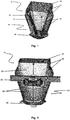
- the passive solar-position tracking device 11 and solar concentrator comprises a hollow parallelepiped housing 14 which is penetrated by the incoming solar radiation through the primary concentrator lens 12 located at the upper end of the parallelepiped housing 14 into a discriminating reflector 18 positioned at the lower end of the same housing 14, when the sun's position is close to the normal/perpendicular position of the tracking device 11.
- the parallelepiped casing 14 has an inverted frusto-conical parallelepiped type shape. It comprises a multitude of arched reflective side surfaces 16 of the curved-concave reflective side surface type to reflect the solar radiation onto the absorbing side chambers when the sun's position is far from perfect alignment with the normal/perpendicular position of the tracking device 11.
- the tracking device 11 is mechanically coupled to an actuator piston 21 positioned near the centre of gravity of the parallelepiped housing 14 comprising fixed and rotatable tools to allow a rotational movement without displacement of the tracking device 11 from an initial position corresponding to sunrise and to an end position relative to sunset, and vice versa.
- At least two opposite side surfaces 16 have a lower section adjacent to the lower end of the parallelepiped housing 14 with a Fresnel-type profile and an upper section adjacent to the upper end of the same parallelepiped housing 14 which has a lateral lens 13 of the linear lens type and which makes the incoming solar radiation linearly converge on the radiation-absorbing side chamber 17 opposite the corresponding lateral lens 13, when the sun is in a low position on the horizon at sunrise and sunset.
- the lateral surfaces 16 are arranged facing respectively different opposite cardinal points, so that a primary surface 16 is positioned towards the eastern cardinal point and a second surface 16 is positioned towards the western cardinal point.
- At least two opposing side surfaces 16 have a lower portion adjacent to the lower end with a Fresnel-type profile and an upper portion 15 adjacent to the upper end of the parallelepiped housing 14 where the actuator piston 21 is located.
- the side surfaces 16 are positioned facing opposite cardinal points respectively so that a third surface 16 is positioned towards the northern cardinal point and a fourth surface 16 is positioned towards the southern cardinal point.
- the frusto-conical parallelepiped casing 14 comprises the primary lens 12 concentrator of the Fresnel-lens type, mechanically coupled to the upper end of the parallelepiped housing 14 to concentrate the solar radiation on a focal point located in proximity to or on the discriminating reflector 18 when the sun's position is close to the normal/perpendicular position of the primary lens.
- the primary concentrator lens 12 has a flat upper and lower Fresnel profile that concentrates the solar radiation on the focal point of the discriminating reflector 18 when the sun's incident rays are perpendicular to the primary lens 12; on-axis condition.
- the discriminating reflector 18 comprises at least two reflective surfaces 51, having, respectively, an arched, curved-concave or similar cross-section in an inverted V-shape that projects the concentrated solar radiation towards the corresponding radiation-absorbing side chamber 17.
- the apex of the inverted arched V corresponds to the focal point of the primary concentrator 12 lens if the sun's position is normal/perpendicular to the primary concentrator 12 lens.
- the reflective surfaces 51 of the discriminating reflector 18 respectively have an arched planar cross-section of the concave plane, parabolic plane, elliptical plane or similar.
- the discriminating reflector 18 is an aspherical lens (not a Fresnel lens), a parabolic revolving mirror, a Fresnel zone plate or similar.
- the solar-position tracking device 11 further comprises at least two radiation-absorbing side chambers 17 facing two by two which contain the working fluid of the liquid, gas or similar type. Therefore, depending on the variation in relative pressure inside the radiation-absorbing side chambers 17, the positioning of the tracking device 11 is automatically changed.
- the pressure increase inside the radiation-absorbing side chambers 17 is transmitted through flexible tubes from the corresponding radiation-absorbing side chamber 17 to the actuator piston 21 so that it guides the rotational movement of the tracking device 11 in coordination with the position of the sun in real time.
- the pressure of the absorbing side chamber on the western side 17 is linked to the eastern side of the east-west actuator piston, and with the increase of pressure in the eastern side of the actuator piston 21, it pushes the east-west actuator piston 21 to the west so that a rotating component of the actuator piston 21 rotates clockwise, causing the tracking device 11 to turn to the east.
- the pressure variation on the eastern or western side of the actuator piston 21 provides real-time tracking of the sun's position along the east-west axis.
- the same tracking mechanism occurs in the north-south seasonal movement, intervening in the north and south radiation-absorbing side chambers and the north-south actuator piston 21 in exactly the same way as the east-west actuator piston 21 described for the daily east-west movement.
- the radiation-absorbing side chambers 17 are closed hollow bodies with an elongated tubular structure of the cylinder type which include pressure communication lines connected between the radiation-absorbing side chamber 17 and the corresponding actuator piston 21 comprising mechanical devices for converting a pressure increase into a rotary movement.
- the radiation-absorbing side chamber 17 is mechanically coupled in a suspended and parallel manner to the corresponding arched reflective inclined side surface 14. It is located between the reflective inclined side surface 17 and the symmetrical axis of the frusto-conical parallelepiped housing. turn, the working fluid is heated to high temperatures in order to increase the internal pressure of the radiation-absorbing side chamber 17 itself, by direct solar radiation and/or radiation reflected by the internal surfaces of the parallelepiped frusto-conical housing.
- the arched reflective inclined side surfaces 16 of the frusto-conical parallelepiped housing 14 reflect the received solar radiation towards the corresponding radiation-absorbing side chamber 17 arranged parallel to and at a predetermined distance from the arched reflective inclined side surface 16 to reflect the radiation.
- This impacts on the respective absorbing side chamber 17 causing it to heat up, and consequently causes a volumetric expansion by pressure that is transmitted towards the rotary axis of the tracking device 11, providing it with a rotational movement in real time, a function of the internal pressure of the radiation-absorbing side chambers 17 as they search for the most appropriate orientation according to the position of the sun.
- the lateral tubular radiation-absorbing chambers are arranged in a cross on the east-west and north-south axes according to the cardinal points, and may be within the same tracking device 11 or in two tracking devices 11 where a first tracking device 11 performs the east-west movement and a second tracking device 11 performs the north-south movement of tracking the sun's position.
- the radiation-absorbing side chamber 17 is made of glass or another transparent material adapted to contain the working fluid.
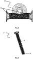
- a thin concentric annular tube 41 is provided inside the radiation absorbing side chamber 1.
- the tube 41 is of a type of material such as metal which is darkened so that incoming solar radiation passes through the transparent wall of the side chamber 17 and is absorbed by the metal tube 41 which directly heats the working fluid.
- the arrangement with glass or another transparent material may distinguish the wavelengths of solar radiation to provide a greenhouse effect and thus limit indoor-energy losses due to radiation.
- the thin tube 41 features an oblique hole 42 arranged at the bottom end of the tube 41 facing the discriminating reflector 18 so that the radiation reflected by the same discriminating reflector 18 enters the thin tube 41 through the oblique hole 42 and thus produces heating in the inner part of the thin tube 41.
- the thin tube 41 has an uncoated lower section with relatively high reflectivity, so that the solar radiation incident on the lower section is additionally reflected in a more scattered manner to an upper section of the thin tube 14 in order to increase the diffusion of the solar radiation and produce a more homogeneous heating.
- the solar-position tracking device 11 is shown with different entry angles of direct solar radiation and details how the precise differentiation of the concentrated incoming solar radiation is produced in an on-axis condition and, therefore, the concentrated solar radiation falls on the focal point, the vertex of the discriminating reflector 18, reflecting the solar radiation on two radiation-absorbing side chambers 17 located in accordance with the eastern and western cardinal points respectively, an equal portion of the solar radiation is directed into either of the radiation-absorbing side chambers 17 positioned opposite one another.
- the tracking device 11 may be misaligned with the sun in an off-axis condition such as in figure 6 .
- a misalignment is shown with an angle of 5° between the vertical and the position of the sun and, therefore, the focus of the concentrated incoming solar radiation is located on one of the reflecting surfaces 51 of the discriminating reflector 18, so that the aforementioned reflecting surface 51 directs all the concentrated incoming solar radiation to the corresponding radiation-absorbing side chamber 17.
- the western radiation-absorbing side chamber 17 is operational and the eastern radiation-absorbing side chamber 17 is idle.
- the discriminating reflector 18 has a through-slot 52 that allows some of the solar radiation to pass through the same slot 52 so that the remainder of the incoming solar radiation is directed into the corresponding absorbing side chamber 17 based on the sun's position.
- the through-slot 52 takes on different shapes, e.g. an elongated shape arranged so that its smaller dimension, its width, is crossed by the focal point generated by the primary lens 12.
- a lower receiver 71 of the lower thermal receiver type is provided below the through-slot 52 to produce thermal energy when the tracking device 11 is in normal/perpendicular position with respect to the axis position; e.g. a liquid fluid circulating inside the lower thermal receiver 71 is heated to heat water for domestic water or another purpose.
- a lower photovoltaic cell is positioned below the through-slot 52 to produce electrical energy.
- the lower receiving radiation collector 71 receives the solar radiation that the discriminating reflector 18 does not reflect back into the absorbing side chambers 17.
- the discriminating reflector 18 comprises four reflective surfaces 51 in the shape of an inverted arched V positioned in a cross, which projects the concentrated incoming solar radiation into one of the four radiation-absorbing side chambers 17 arranged in a cross within the parallelepiped housing 14 of a single tracking device 11, which can be rotated along the two east-west and north-south axes.
- the discriminating reflector 18 is divided into at least four curved reflecting surfaces 51 to direct the concentrated solar radiation to one of the four corresponding radiation-absorbing side chambers 17 in order to produce the expansion of the working fluid so that the pressure within two side chambers 17 increases and is transmitted to the corresponding ends of the actuating pistons 21 to trigger rotation along the two east-west and north-south axes.
- the rotation along an axis occurs in either absorbing side chamber because of an increase in pressure and/or volumetric expansion of the working fluid i.e. in the east or west chamber, and in the north or south chamber.
- the tracking device 11 is adapted to include a mechanism that provides a return force contrary to the rotational movement provided by an absorbing side chamber; the mechanism is a spring, counterweight, pressurised cylinder, or similar type of component. Therefore, the discriminating reflector 18 exhibits the absence of a non-active reflective surface 111. In other words, the discriminating reflector 18 does not physically extend over the entire area of the lower end of the parallelepiped housing, which is a non-active part thereof.
- a lower radiation collector with larger dimensions 71 can be arranged to transform the concentrated solar radiation into thermal or electrical energy for all the angles that correspond to this area.
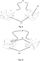
- a frontal perspective view shows the solar-position tracking device 11 that tracks the solar concentration which guides, in real time, the orientation of a multitude of devices for the use of photovoltaic and/or thermal energy.
- Figure 13 shows a posterior perspective view of the same device and configuration.
- Figures 12 and 13 show the directions according to the cardinal points, which assume that the system is mounted in the northern hemisphere. For use in the southern hemisphere, the assembly would be rotated 180° to point north.
- a rigid vertical frame 141 is fixed to the floor and fitted with swivel joints that allow the assembly of a multitude of swivel frames 142 that rotate around the east-west axis.
- Each rotation frame 141 is fitted with swivel joints that enable the installation of a number of tracking devices 11 which are traction units that guide the movement of tracking components for the use of photovoltaic and/or thermal energy.
- a rigid bar mechanically couples several energy-collecting tracking components with the tracking device 11 so that they rotate simultaneously. In this way, the rotation of the tracking device 11 is automatically transferred to the energy-collecting components.
- the operation of the two-axis tracking device 11 is similar, with the exception that it is connected to two rotating systems.
- the first axis causes a movement in the east-west direction with respect to the swivel frame, as in single-axis tractor units, and the second axis provides a rotation of the swivel frame in the north-south direction. All swivel frames are connected by mechanical joints that provide a rotation on both axes to the energy-collecting components.
- Figure 13 shows a rear perspective view of the solar-concentration tracking device 11, which guides the orientation of the photovoltaic- and/or thermal-energy arrangement where at least one concentration tracking device 11 is combined with a multitude of energy-collecting components arranged on a rotatable frame in such a way as to allow the arrangement to rotate in the direction of elevation so that the optical axes of the energy-harvesting components move closer or further away from the zenith.
- the swivel frame is mounted on a fixed frame 141 such as a single post or pedestal, in such a way as to enable the swivel frame 142 to be rotated in the azimuth direction.
- a second mechanical tool is provided to cause this rotation.
- Communication between the primary actuator piston 21 and the rotating component can be carried out by means of a cable generating a longitudinal rack on the primary actuator piston 21 that engages with a toothed circular pinion fitted to the rotating component.
- the flexible elastomer membranes or diaphragms 31 are arranged at the opposite ends of the actuator piston 21 in such a way that the pressure thrust on the actuator piston 21 occurs in a smooth, progressive and precise manner by folding and unfolding the membranes 31 and triggering the friction of the actuator piston 21 on the piston cylinder liner.
- the concentrator tracking device 11 is arranged according to the four cardinal points that divide the horizon into equal parts, so that each side surface 16 of the parallelepiped 14 housing looks directly into a cardinal point so that the side surfaces 16 of the parallelepiped 14 housing can be identified as the north side surface, east side surface, south side surface and west side surface.
- a radiation absorbing side chamber 17 is respectively located close to the centre of the east, west, north, and south inclined, arched side surface 14.
Landscapes
- Engineering & Computer Science (AREA)
- Physics & Mathematics (AREA)
- Sustainable Development (AREA)
- Life Sciences & Earth Sciences (AREA)
- Chemical & Material Sciences (AREA)
- Mechanical Engineering (AREA)
- Sustainable Energy (AREA)
- Thermal Sciences (AREA)
- General Engineering & Computer Science (AREA)
- Combustion & Propulsion (AREA)
- General Physics & Mathematics (AREA)
- Optics & Photonics (AREA)
- Automation & Control Theory (AREA)
- Health & Medical Sciences (AREA)
- Toxicology (AREA)
- Photovoltaic Devices (AREA)
- Casting Or Compression Moulding Of Plastics Or The Like (AREA)
- Optical Elements Other Than Lenses (AREA)
Applications Claiming Priority (1)
| Application Number | Priority Date | Filing Date | Title |
|---|---|---|---|
| PCT/ES2018/070303 WO2019197689A1 (es) | 2018-04-13 | 2018-04-13 | Dispositivo seguidor |
Publications (4)
| Publication Number | Publication Date |
|---|---|
| EP3779321A1 true EP3779321A1 (de) | 2021-02-17 |
| EP3779321A4 EP3779321A4 (de) | 2021-05-05 |
| EP3779321B1 EP3779321B1 (de) | 2023-10-18 |
| EP3779321C0 EP3779321C0 (de) | 2023-10-18 |
Family
ID=68163937
Family Applications (1)
| Application Number | Title | Priority Date | Filing Date |
|---|---|---|---|
| EP18914062.7A Active EP3779321B1 (de) | 2018-04-13 | 2018-04-13 | Verfolgungsvorrichtung |
Country Status (16)
| Country | Link |
|---|---|
| US (1) | US11431287B2 (de) |
| EP (1) | EP3779321B1 (de) |
| JP (1) | JP7146298B2 (de) |
| KR (1) | KR102461966B1 (de) |
| CN (1) | CN112005061B (de) |
| AR (1) | AR114772A1 (de) |
| AU (1) | AU2018418302A1 (de) |
| BR (1) | BR112020020612A2 (de) |
| CO (1) | CO2020013504A2 (de) |
| ES (1) | ES2965543T3 (de) |
| IL (1) | IL277825B2 (de) |
| MX (1) | MX2020010771A (de) |
| PY (1) | PY1925560A (de) |
| UY (1) | UY38176A (de) |
| WO (1) | WO2019197689A1 (de) |
| ZA (1) | ZA202006681B (de) |
Families Citing this family (1)
| Publication number | Priority date | Publication date | Assignee | Title |
|---|---|---|---|---|
| CN113467524B (zh) * | 2021-08-05 | 2024-02-13 | 安徽理工大学 | 一种新型的太阳追踪仪 |
Family Cites Families (22)
| Publication number | Priority date | Publication date | Assignee | Title |
|---|---|---|---|---|
| JPS5316985Y2 (de) * | 1973-11-13 | 1978-05-06 | ||
| JPS5638863B2 (de) * | 1975-03-13 | 1981-09-09 | ||
| US4027651A (en) | 1976-02-17 | 1977-06-07 | Robbins Jr Roland W | Solar-energy-powered sun tracker |
| NL7610401A (nl) * | 1976-09-20 | 1978-03-22 | Philips Nv | Zonnecollector voorzien van zonnevolgmiddelen. |
| NL7701812A (nl) | 1977-02-21 | 1978-08-23 | Philips Nv | Zonnecollector, voorzien van zonnevolgmiddelen. |
| US4158356A (en) | 1977-02-22 | 1979-06-19 | Wininger David V | Self-powered tracking solar collector |
| US4211212A (en) | 1977-10-05 | 1980-07-08 | Braun Raymond J | Solar refrigeration system |
| US4306541A (en) * | 1979-06-27 | 1981-12-22 | University Of Florida | Solar energy powered sun tracking device |
| US4275712A (en) * | 1979-10-25 | 1981-06-30 | Baer Stephen C | Sun tracking device employing displaced heating surfaces for automatic morning reorientation |
| US4352350A (en) * | 1979-11-19 | 1982-10-05 | Johnson Carl W | Means for tracking the sun |
| IT1144124B (it) * | 1981-02-27 | 1986-10-29 | Fiat Ricerche | Dispositivo di inseguimento del moto apparente del sole per collettori di energia solare |
| GR1003941B (el) * | 2001-06-28 | 2002-07-05 | Ιωαννης Τσιμερικας | Ηλιακος συλλεκτης που ακολουθει τη θεση του ηλιου, με πηγη ενεργειας την ιδια την ηλιακη ακτινοβολια. |
| JP2005062785A (ja) * | 2003-08-08 | 2005-03-10 | Yozo Oko | 追尾型集光装置 |
| WO2007087343A2 (en) * | 2006-01-25 | 2007-08-02 | Intematix Corporation | Solar modules with tracking and concentrating features |
| MY147928A (en) * | 2008-09-18 | 2013-02-15 | Mimos Berhad | Apparatus for solar tracking of energy harvester |
| US8342169B2 (en) * | 2009-01-05 | 2013-01-01 | Kenergy Scientific, Inc. | Reciprocating solar engine with solar reflectors |
| DE102009049471B3 (de) * | 2009-10-15 | 2011-04-07 | Schott Solar Ag | Strahlungsselektive Absorberbeschichtung und Absorberrohr mit strahlungsselektiver Absorberbeschichtung |
| US20110100354A1 (en) * | 2009-10-29 | 2011-05-05 | Cn-J Technology Co., Ltd. | Non-electrically-powered sun-tracking solar system |
| JP2013520785A (ja) * | 2010-02-10 | 2013-06-06 | クアドラ・ソーラー・コーポレーション | 集中型太陽光発電及び熱システム |
| PL2674690T3 (pl) * | 2011-02-11 | 2019-06-28 | Jaime CASELLES FORNÉS | Bezpośrednie zbieranie promieniowania słonecznego i element koncentrowania |
| CN102706004A (zh) * | 2012-06-21 | 2012-10-03 | 镇江市博林光电科技有限公司 | 聚焦式太阳能集热装置及集热系统 |
| JP2017096571A (ja) * | 2015-11-25 | 2017-06-01 | 千代田化工建設株式会社 | 太陽追尾装置 |
-
2018
- 2018-04-13 CN CN201880092370.9A patent/CN112005061B/zh not_active Expired - Fee Related
- 2018-04-13 IL IL277825A patent/IL277825B2/en unknown
- 2018-04-13 KR KR1020207030726A patent/KR102461966B1/ko active Active
- 2018-04-13 WO PCT/ES2018/070303 patent/WO2019197689A1/es not_active Ceased
- 2018-04-13 AU AU2018418302A patent/AU2018418302A1/en not_active Abandoned
- 2018-04-13 MX MX2020010771A patent/MX2020010771A/es unknown
- 2018-04-13 JP JP2020555771A patent/JP7146298B2/ja active Active
- 2018-04-13 EP EP18914062.7A patent/EP3779321B1/de active Active
- 2018-04-13 BR BR112020020612-1A patent/BR112020020612A2/pt active Search and Examination
- 2018-04-13 ES ES18914062T patent/ES2965543T3/es active Active
- 2018-04-13 US US17/047,168 patent/US11431287B2/en active Active
-
2019
- 2019-04-01 PY PY201901925560A patent/PY1925560A/es unknown
- 2019-04-08 UY UY38176A patent/UY38176A/es not_active Application Discontinuation
- 2019-04-11 AR ARP190100958A patent/AR114772A1/es active IP Right Grant
-
2020
- 2020-10-27 CO CONC2020/0013504A patent/CO2020013504A2/es unknown
- 2020-10-27 ZA ZA2020/06681A patent/ZA202006681B/en unknown
Also Published As
| Publication number | Publication date |
|---|---|
| CO2020013504A2 (es) | 2020-12-10 |
| WO2019197689A1 (es) | 2019-10-17 |
| AU2018418302A1 (en) | 2020-11-19 |
| IL277825B1 (en) | 2023-12-01 |
| BR112020020612A2 (pt) | 2021-01-12 |
| MX2020010771A (es) | 2020-12-09 |
| IL277825A (en) | 2020-11-30 |
| JP2021525352A (ja) | 2021-09-24 |
| CN112005061B (zh) | 2023-03-28 |
| ZA202006681B (en) | 2023-01-25 |
| JP7146298B2 (ja) | 2022-10-04 |
| CN112005061A (zh) | 2020-11-27 |
| US11431287B2 (en) | 2022-08-30 |
| KR20200143401A (ko) | 2020-12-23 |
| EP3779321B1 (de) | 2023-10-18 |
| IL277825B2 (en) | 2024-04-01 |
| EP3779321C0 (de) | 2023-10-18 |
| AR114772A1 (es) | 2020-10-14 |
| ES2965543T3 (es) | 2024-04-15 |
| EP3779321A4 (de) | 2021-05-05 |
| PY1925560A (es) | 2019-10-15 |
| KR102461966B1 (ko) | 2022-11-01 |
| UY38176A (es) | 2019-10-31 |
| US20210159847A1 (en) | 2021-05-27 |
Similar Documents
| Publication | Publication Date | Title |
|---|---|---|
| US3996917A (en) | Solar heating apparatus | |
| US4459972A (en) | Heliostat assembly | |
| WO1980000271A1 (en) | Self-contained solar tracking device | |
| US4230094A (en) | Solar concentrator | |
| US4572160A (en) | Heliotropic solar heat collector system | |
| WO2011014086A2 (en) | Modular system for concentration of solar radiation | |
| US20100043777A1 (en) | Solar collector system | |
| Dang | Concentrators: a review | |
| US11431287B2 (en) | Tracking device | |
| EP2016344B1 (de) | Hyperbolisches solarrinnenfeldsystem | |
| US4137902A (en) | Energy concentrator system | |
| CA3025955A1 (en) | Sun tracking solar system | |
| HK40033381B (en) | Tracking device | |
| HK40033381A (en) | Tracking device | |
| EP2591293B1 (de) | Vorrichtung zur gewinnung von solarenergie | |
| EP3221650B1 (de) | Sonnenkonzentrator mit beabstandeten schwenkbaren verbindungen | |
| RU2661169C1 (ru) | Многозеркальная гелиоустановка с общим приводом системы ориентации | |
| Rabl | Prisms with total internal reflection as solar reflectors | |
| Galal | Theoretical analysis of a variable aperture solar tower receiver | |
| Galal et al. | Solar Central Receiver with an Irising Aperture | |
| MX2013014283A (es) | Horno solar, campo de heliostatos para dispersas aplicaciones y sistema formado por los mismos. | |
| GB2506573A (en) | Linear Fresnel Solar Concentrator |
Legal Events
| Date | Code | Title | Description |
|---|---|---|---|
| STAA | Information on the status of an ep patent application or granted ep patent |
Free format text: STATUS: THE INTERNATIONAL PUBLICATION HAS BEEN MADE |
|
| PUAI | Public reference made under article 153(3) epc to a published international application that has entered the european phase |
Free format text: ORIGINAL CODE: 0009012 |
|
| STAA | Information on the status of an ep patent application or granted ep patent |
Free format text: STATUS: REQUEST FOR EXAMINATION WAS MADE |
|
| 17P | Request for examination filed |
Effective date: 20201113 |
|
| AK | Designated contracting states |
Kind code of ref document: A1 Designated state(s): AL AT BE BG CH CY CZ DE DK EE ES FI FR GB GR HR HU IE IS IT LI LT LU LV MC MK MT NL NO PL PT RO RS SE SI SK SM TR |
|
| AX | Request for extension of the european patent |
Extension state: BA ME |
|
| A4 | Supplementary search report drawn up and despatched |
Effective date: 20210406 |
|
| RIC1 | Information provided on ipc code assigned before grant |
Ipc: F24S 50/20 20180101AFI20210329BHEP Ipc: F24S 30/40 20180101ALI20210329BHEP Ipc: H02S 20/32 20140101ALI20210329BHEP Ipc: F24S 23/30 20180101ALI20210329BHEP Ipc: F24S 23/70 20180101ALI20210329BHEP Ipc: F24S 30/425 20180101ALI20210329BHEP Ipc: F24S 30/00 20180101ALN20210329BHEP Ipc: F24S 23/74 20180101ALN20210329BHEP Ipc: F24S 23/77 20180101ALN20210329BHEP |
|
| DAV | Request for validation of the european patent (deleted) | ||
| DAX | Request for extension of the european patent (deleted) | ||
| GRAP | Despatch of communication of intention to grant a patent |
Free format text: ORIGINAL CODE: EPIDOSNIGR1 |
|
| STAA | Information on the status of an ep patent application or granted ep patent |
Free format text: STATUS: GRANT OF PATENT IS INTENDED |
|
| RIC1 | Information provided on ipc code assigned before grant |
Ipc: F24S 23/77 20180101ALN20230421BHEP Ipc: F24S 23/74 20180101ALN20230421BHEP Ipc: F24S 30/00 20180101ALN20230421BHEP Ipc: F24S 30/425 20180101ALI20230421BHEP Ipc: F24S 23/70 20180101ALI20230421BHEP Ipc: F24S 23/30 20180101ALI20230421BHEP Ipc: H02S 20/32 20140101ALI20230421BHEP Ipc: F24S 30/40 20180101ALI20230421BHEP Ipc: F24S 50/20 20180101AFI20230421BHEP |
|
| RIC1 | Information provided on ipc code assigned before grant |
Ipc: F24S 23/77 20180101ALN20230428BHEP Ipc: F24S 23/74 20180101ALN20230428BHEP Ipc: F24S 30/00 20180101ALN20230428BHEP Ipc: F24S 30/425 20180101ALI20230428BHEP Ipc: F24S 23/70 20180101ALI20230428BHEP Ipc: F24S 23/30 20180101ALI20230428BHEP Ipc: H02S 20/32 20140101ALI20230428BHEP Ipc: F24S 30/40 20180101ALI20230428BHEP Ipc: F24S 50/20 20180101AFI20230428BHEP |
|
| INTG | Intention to grant announced |
Effective date: 20230519 |
|
| GRAS | Grant fee paid |
Free format text: ORIGINAL CODE: EPIDOSNIGR3 |
|
| GRAA | (expected) grant |
Free format text: ORIGINAL CODE: 0009210 |
|
| STAA | Information on the status of an ep patent application or granted ep patent |
Free format text: STATUS: THE PATENT HAS BEEN GRANTED |
|
| AK | Designated contracting states |
Kind code of ref document: B1 Designated state(s): AL AT BE BG CH CY CZ DE DK EE ES FI FR GB GR HR HU IE IS IT LI LT LU LV MC MK MT NL NO PL PT RO RS SE SI SK SM TR |
|
| REG | Reference to a national code |
Ref country code: GB Ref legal event code: FG4D |
|
| REG | Reference to a national code |
Ref country code: CH Ref legal event code: EP |
|
| REG | Reference to a national code |
Ref country code: IE Ref legal event code: FG4D |
|
| REG | Reference to a national code |
Ref country code: DE Ref legal event code: R096 Ref document number: 602018059773 Country of ref document: DE |
|
| U01 | Request for unitary effect filed |
Effective date: 20231116 |
|
| U07 | Unitary effect registered |
Designated state(s): AT BE BG DE DK EE FI FR IT LT LU LV MT NL PT SE SI Effective date: 20231124 |
|
| REG | Reference to a national code |
Ref country code: GR Ref legal event code: EP Ref document number: 20230402530 Country of ref document: GR Effective date: 20240209 |
|
| PG25 | Lapsed in a contracting state [announced via postgrant information from national office to epo] |
Ref country code: IS Free format text: LAPSE BECAUSE OF FAILURE TO SUBMIT A TRANSLATION OF THE DESCRIPTION OR TO PAY THE FEE WITHIN THE PRESCRIBED TIME-LIMIT Effective date: 20240218 |
|
| REG | Reference to a national code |
Ref country code: ES Ref legal event code: FG2A Ref document number: 2965543 Country of ref document: ES Kind code of ref document: T3 Effective date: 20240415 |
|
| PG25 | Lapsed in a contracting state [announced via postgrant information from national office to epo] |
Ref country code: IS Free format text: LAPSE BECAUSE OF FAILURE TO SUBMIT A TRANSLATION OF THE DESCRIPTION OR TO PAY THE FEE WITHIN THE PRESCRIBED TIME-LIMIT Effective date: 20240218 |
|
| PG25 | Lapsed in a contracting state [announced via postgrant information from national office to epo] |
Ref country code: RS Free format text: LAPSE BECAUSE OF FAILURE TO SUBMIT A TRANSLATION OF THE DESCRIPTION OR TO PAY THE FEE WITHIN THE PRESCRIBED TIME-LIMIT Effective date: 20231018 Ref country code: PL Free format text: LAPSE BECAUSE OF FAILURE TO SUBMIT A TRANSLATION OF THE DESCRIPTION OR TO PAY THE FEE WITHIN THE PRESCRIBED TIME-LIMIT Effective date: 20231018 Ref country code: NO Free format text: LAPSE BECAUSE OF FAILURE TO SUBMIT A TRANSLATION OF THE DESCRIPTION OR TO PAY THE FEE WITHIN THE PRESCRIBED TIME-LIMIT Effective date: 20240118 Ref country code: HR Free format text: LAPSE BECAUSE OF FAILURE TO SUBMIT A TRANSLATION OF THE DESCRIPTION OR TO PAY THE FEE WITHIN THE PRESCRIBED TIME-LIMIT Effective date: 20231018 |
|
| REG | Reference to a national code |
Ref country code: DE Ref legal event code: R097 Ref document number: 602018059773 Country of ref document: DE |
|
| PG25 | Lapsed in a contracting state [announced via postgrant information from national office to epo] |
Ref country code: CZ Free format text: LAPSE BECAUSE OF FAILURE TO SUBMIT A TRANSLATION OF THE DESCRIPTION OR TO PAY THE FEE WITHIN THE PRESCRIBED TIME-LIMIT Effective date: 20231018 |
|
| PG25 | Lapsed in a contracting state [announced via postgrant information from national office to epo] |
Ref country code: SK Free format text: LAPSE BECAUSE OF FAILURE TO SUBMIT A TRANSLATION OF THE DESCRIPTION OR TO PAY THE FEE WITHIN THE PRESCRIBED TIME-LIMIT Effective date: 20231018 |
|
| PG25 | Lapsed in a contracting state [announced via postgrant information from national office to epo] |
Ref country code: SM Free format text: LAPSE BECAUSE OF FAILURE TO SUBMIT A TRANSLATION OF THE DESCRIPTION OR TO PAY THE FEE WITHIN THE PRESCRIBED TIME-LIMIT Effective date: 20231018 Ref country code: SK Free format text: LAPSE BECAUSE OF FAILURE TO SUBMIT A TRANSLATION OF THE DESCRIPTION OR TO PAY THE FEE WITHIN THE PRESCRIBED TIME-LIMIT Effective date: 20231018 Ref country code: RO Free format text: LAPSE BECAUSE OF FAILURE TO SUBMIT A TRANSLATION OF THE DESCRIPTION OR TO PAY THE FEE WITHIN THE PRESCRIBED TIME-LIMIT Effective date: 20231018 Ref country code: CZ Free format text: LAPSE BECAUSE OF FAILURE TO SUBMIT A TRANSLATION OF THE DESCRIPTION OR TO PAY THE FEE WITHIN THE PRESCRIBED TIME-LIMIT Effective date: 20231018 |
|
| PLBE | No opposition filed within time limit |
Free format text: ORIGINAL CODE: 0009261 |
|
| STAA | Information on the status of an ep patent application or granted ep patent |
Free format text: STATUS: NO OPPOSITION FILED WITHIN TIME LIMIT |
|
| 26N | No opposition filed |
Effective date: 20240719 |
|
| PG25 | Lapsed in a contracting state [announced via postgrant information from national office to epo] |
Ref country code: MC Free format text: LAPSE BECAUSE OF FAILURE TO SUBMIT A TRANSLATION OF THE DESCRIPTION OR TO PAY THE FEE WITHIN THE PRESCRIBED TIME-LIMIT Effective date: 20231018 |
|
| PG25 | Lapsed in a contracting state [announced via postgrant information from national office to epo] |
Ref country code: MC Free format text: LAPSE BECAUSE OF FAILURE TO SUBMIT A TRANSLATION OF THE DESCRIPTION OR TO PAY THE FEE WITHIN THE PRESCRIBED TIME-LIMIT Effective date: 20231018 |
|
| REG | Reference to a national code |
Ref country code: CH Ref legal event code: PL |
|
| U90 | Renewal fees not paid: noting of loss of rights |
Free format text: RENEWAL FEE NOT PAID FOR YEAR 07 Effective date: 20241118 |
|
| GBPC | Gb: european patent ceased through non-payment of renewal fee |
Effective date: 20240413 |
|
| PG25 | Lapsed in a contracting state [announced via postgrant information from national office to epo] |
Ref country code: GR Free format text: LAPSE BECAUSE OF NON-PAYMENT OF DUE FEES Effective date: 20241104 |
|
| PG25 | Lapsed in a contracting state [announced via postgrant information from national office to epo] |
Ref country code: GB Free format text: LAPSE BECAUSE OF NON-PAYMENT OF DUE FEES Effective date: 20240413 |
|
| PG25 | Lapsed in a contracting state [announced via postgrant information from national office to epo] |
Ref country code: GR Free format text: LAPSE BECAUSE OF NON-PAYMENT OF DUE FEES Effective date: 20241104 Ref country code: GB Free format text: LAPSE BECAUSE OF NON-PAYMENT OF DUE FEES Effective date: 20240413 Ref country code: CH Free format text: LAPSE BECAUSE OF NON-PAYMENT OF DUE FEES Effective date: 20240430 |
|
| U93 | Unitary patent lapsed |
Free format text: RENEWAL FEE NOT PAID Effective date: 20240430 |
|
| PG25 | Lapsed in a contracting state [announced via postgrant information from national office to epo] |
Ref country code: IE Free format text: LAPSE BECAUSE OF NON-PAYMENT OF DUE FEES Effective date: 20240413 |
|
| REG | Reference to a national code |
Ref country code: ES Ref legal event code: FD2A Effective date: 20250528 |
|
| PG25 | Lapsed in a contracting state [announced via postgrant information from national office to epo] |
Ref country code: ES Free format text: LAPSE BECAUSE OF NON-PAYMENT OF DUE FEES Effective date: 20240414 |
|
| PG25 | Lapsed in a contracting state [announced via postgrant information from national office to epo] |
Ref country code: CY Free format text: LAPSE BECAUSE OF FAILURE TO SUBMIT A TRANSLATION OF THE DESCRIPTION OR TO PAY THE FEE WITHIN THE PRESCRIBED TIME-LIMIT; INVALID AB INITIO Effective date: 20180413 |
|
| PG25 | Lapsed in a contracting state [announced via postgrant information from national office to epo] |
Ref country code: HU Free format text: LAPSE BECAUSE OF FAILURE TO SUBMIT A TRANSLATION OF THE DESCRIPTION OR TO PAY THE FEE WITHIN THE PRESCRIBED TIME-LIMIT; INVALID AB INITIO Effective date: 20180413 |