EP3779318A1 - Air conditioning device - Google Patents
Air conditioning device Download PDFInfo
- Publication number
- EP3779318A1 EP3779318A1 EP18914221.9A EP18914221A EP3779318A1 EP 3779318 A1 EP3779318 A1 EP 3779318A1 EP 18914221 A EP18914221 A EP 18914221A EP 3779318 A1 EP3779318 A1 EP 3779318A1
- Authority
- EP
- European Patent Office
- Prior art keywords
- air
- header
- condenser
- heat transfer
- evaporator
- Prior art date
- Legal status (The legal status is an assumption and is not a legal conclusion. Google has not performed a legal analysis and makes no representation as to the accuracy of the status listed.)
- Withdrawn
Links
Images


Classifications
-
- F—MECHANICAL ENGINEERING; LIGHTING; HEATING; WEAPONS; BLASTING
- F28—HEAT EXCHANGE IN GENERAL
- F28D—HEAT-EXCHANGE APPARATUS, NOT PROVIDED FOR IN ANOTHER SUBCLASS, IN WHICH THE HEAT-EXCHANGE MEDIA DO NOT COME INTO DIRECT CONTACT
- F28D1/00—Heat-exchange apparatus having stationary conduit assemblies for one heat-exchange medium only, the media being in contact with different sides of the conduit wall, in which the other heat-exchange medium is a large body of fluid, e.g. domestic or motor car radiators
- F28D1/02—Heat-exchange apparatus having stationary conduit assemblies for one heat-exchange medium only, the media being in contact with different sides of the conduit wall, in which the other heat-exchange medium is a large body of fluid, e.g. domestic or motor car radiators with heat-exchange conduits immersed in the body of fluid
- F28D1/0233—Heat-exchange apparatus having stationary conduit assemblies for one heat-exchange medium only, the media being in contact with different sides of the conduit wall, in which the other heat-exchange medium is a large body of fluid, e.g. domestic or motor car radiators with heat-exchange conduits immersed in the body of fluid with air flow channels
- F28D1/024—Heat-exchange apparatus having stationary conduit assemblies for one heat-exchange medium only, the media being in contact with different sides of the conduit wall, in which the other heat-exchange medium is a large body of fluid, e.g. domestic or motor car radiators with heat-exchange conduits immersed in the body of fluid with air flow channels with an air driving element
-
- F—MECHANICAL ENGINEERING; LIGHTING; HEATING; WEAPONS; BLASTING
- F25—REFRIGERATION OR COOLING; COMBINED HEATING AND REFRIGERATION SYSTEMS; HEAT PUMP SYSTEMS; MANUFACTURE OR STORAGE OF ICE; LIQUEFACTION SOLIDIFICATION OF GASES
- F25B—REFRIGERATION MACHINES, PLANTS OR SYSTEMS; COMBINED HEATING AND REFRIGERATION SYSTEMS; HEAT PUMP SYSTEMS
- F25B39/00—Evaporators; Condensers
-
- F—MECHANICAL ENGINEERING; LIGHTING; HEATING; WEAPONS; BLASTING
- F24—HEATING; RANGES; VENTILATING
- F24F—AIR-CONDITIONING; AIR-HUMIDIFICATION; VENTILATION; USE OF AIR CURRENTS FOR SCREENING
- F24F1/00—Room units for air-conditioning, e.g. separate or self-contained units or units receiving primary air from a central station
- F24F1/02—Self-contained room units for air-conditioning, i.e. with all apparatus for treatment installed in a common casing
- F24F1/022—Self-contained room units for air-conditioning, i.e. with all apparatus for treatment installed in a common casing comprising a compressor cycle
-
- F—MECHANICAL ENGINEERING; LIGHTING; HEATING; WEAPONS; BLASTING
- F24—HEATING; RANGES; VENTILATING
- F24F—AIR-CONDITIONING; AIR-HUMIDIFICATION; VENTILATION; USE OF AIR CURRENTS FOR SCREENING
- F24F1/00—Room units for air-conditioning, e.g. separate or self-contained units or units receiving primary air from a central station
- F24F1/02—Self-contained room units for air-conditioning, i.e. with all apparatus for treatment installed in a common casing
- F24F1/032—Self-contained room units for air-conditioning, i.e. with all apparatus for treatment installed in a common casing characterised by heat exchangers
-
- F—MECHANICAL ENGINEERING; LIGHTING; HEATING; WEAPONS; BLASTING
- F24—HEATING; RANGES; VENTILATING
- F24F—AIR-CONDITIONING; AIR-HUMIDIFICATION; VENTILATION; USE OF AIR CURRENTS FOR SCREENING
- F24F13/00—Details common to, or for air-conditioning, air-humidification, ventilation or use of air currents for screening
- F24F13/22—Means for preventing condensation or evacuating condensate
-
- F—MECHANICAL ENGINEERING; LIGHTING; HEATING; WEAPONS; BLASTING
- F24—HEATING; RANGES; VENTILATING
- F24F—AIR-CONDITIONING; AIR-HUMIDIFICATION; VENTILATION; USE OF AIR CURRENTS FOR SCREENING
- F24F13/00—Details common to, or for air-conditioning, air-humidification, ventilation or use of air currents for screening
- F24F13/22—Means for preventing condensation or evacuating condensate
- F24F13/222—Means for preventing condensation or evacuating condensate for evacuating condensate
-
- F—MECHANICAL ENGINEERING; LIGHTING; HEATING; WEAPONS; BLASTING
- F25—REFRIGERATION OR COOLING; COMBINED HEATING AND REFRIGERATION SYSTEMS; HEAT PUMP SYSTEMS; MANUFACTURE OR STORAGE OF ICE; LIQUEFACTION SOLIDIFICATION OF GASES
- F25B—REFRIGERATION MACHINES, PLANTS OR SYSTEMS; COMBINED HEATING AND REFRIGERATION SYSTEMS; HEAT PUMP SYSTEMS
- F25B39/00—Evaporators; Condensers
- F25B39/04—Condensers
-
- F—MECHANICAL ENGINEERING; LIGHTING; HEATING; WEAPONS; BLASTING
- F28—HEAT EXCHANGE IN GENERAL
- F28D—HEAT-EXCHANGE APPARATUS, NOT PROVIDED FOR IN ANOTHER SUBCLASS, IN WHICH THE HEAT-EXCHANGE MEDIA DO NOT COME INTO DIRECT CONTACT
- F28D1/00—Heat-exchange apparatus having stationary conduit assemblies for one heat-exchange medium only, the media being in contact with different sides of the conduit wall, in which the other heat-exchange medium is a large body of fluid, e.g. domestic or motor car radiators
- F28D1/02—Heat-exchange apparatus having stationary conduit assemblies for one heat-exchange medium only, the media being in contact with different sides of the conduit wall, in which the other heat-exchange medium is a large body of fluid, e.g. domestic or motor car radiators with heat-exchange conduits immersed in the body of fluid
- F28D1/04—Heat-exchange apparatus having stationary conduit assemblies for one heat-exchange medium only, the media being in contact with different sides of the conduit wall, in which the other heat-exchange medium is a large body of fluid, e.g. domestic or motor car radiators with heat-exchange conduits immersed in the body of fluid with tubular conduits
- F28D1/053—Heat-exchange apparatus having stationary conduit assemblies for one heat-exchange medium only, the media being in contact with different sides of the conduit wall, in which the other heat-exchange medium is a large body of fluid, e.g. domestic or motor car radiators with heat-exchange conduits immersed in the body of fluid with tubular conduits the conduits being straight
- F28D1/0535—Heat-exchange apparatus having stationary conduit assemblies for one heat-exchange medium only, the media being in contact with different sides of the conduit wall, in which the other heat-exchange medium is a large body of fluid, e.g. domestic or motor car radiators with heat-exchange conduits immersed in the body of fluid with tubular conduits the conduits being straight the conduits having a non-circular cross-section
- F28D1/05366—Assemblies of conduits connected to common headers, e.g. core type radiators
-
- F—MECHANICAL ENGINEERING; LIGHTING; HEATING; WEAPONS; BLASTING
- F28—HEAT EXCHANGE IN GENERAL
- F28D—HEAT-EXCHANGE APPARATUS, NOT PROVIDED FOR IN ANOTHER SUBCLASS, IN WHICH THE HEAT-EXCHANGE MEDIA DO NOT COME INTO DIRECT CONTACT
- F28D5/00—Heat-exchange apparatus having stationary conduit assemblies for one heat-exchange medium only, the media being in contact with different sides of the conduit wall, using the cooling effect of natural or forced evaporation
-
- F—MECHANICAL ENGINEERING; LIGHTING; HEATING; WEAPONS; BLASTING
- F24—HEATING; RANGES; VENTILATING
- F24F—AIR-CONDITIONING; AIR-HUMIDIFICATION; VENTILATION; USE OF AIR CURRENTS FOR SCREENING
- F24F13/00—Details common to, or for air-conditioning, air-humidification, ventilation or use of air currents for screening
- F24F13/22—Means for preventing condensation or evacuating condensate
- F24F13/222—Means for preventing condensation or evacuating condensate for evacuating condensate
- F24F2013/225—Means for preventing condensation or evacuating condensate for evacuating condensate by evaporating the condensate in the cooling medium, e.g. in air flow from the condenser
-
- F—MECHANICAL ENGINEERING; LIGHTING; HEATING; WEAPONS; BLASTING
- F25—REFRIGERATION OR COOLING; COMBINED HEATING AND REFRIGERATION SYSTEMS; HEAT PUMP SYSTEMS; MANUFACTURE OR STORAGE OF ICE; LIQUEFACTION SOLIDIFICATION OF GASES
- F25B—REFRIGERATION MACHINES, PLANTS OR SYSTEMS; COMBINED HEATING AND REFRIGERATION SYSTEMS; HEAT PUMP SYSTEMS
- F25B2339/00—Details of evaporators; Details of condensers
- F25B2339/04—Details of condensers
- F25B2339/041—Details of condensers of evaporative condensers
-
- F—MECHANICAL ENGINEERING; LIGHTING; HEATING; WEAPONS; BLASTING
- F28—HEAT EXCHANGE IN GENERAL
- F28D—HEAT-EXCHANGE APPARATUS, NOT PROVIDED FOR IN ANOTHER SUBCLASS, IN WHICH THE HEAT-EXCHANGE MEDIA DO NOT COME INTO DIRECT CONTACT
- F28D21/00—Heat-exchange apparatus not covered by any of the groups F28D1/00 - F28D20/00
- F28D2021/0019—Other heat exchangers for particular applications; Heat exchange systems not otherwise provided for
- F28D2021/0068—Other heat exchangers for particular applications; Heat exchange systems not otherwise provided for for refrigerant cycles
-
- F—MECHANICAL ENGINEERING; LIGHTING; HEATING; WEAPONS; BLASTING
- F28—HEAT EXCHANGE IN GENERAL
- F28F—DETAILS OF HEAT-EXCHANGE AND HEAT-TRANSFER APPARATUS, OF GENERAL APPLICATION
- F28F1/00—Tubular elements; Assemblies of tubular elements
- F28F1/10—Tubular elements and assemblies thereof with means for increasing heat-transfer area, e.g. with fins, with projections, with recesses
- F28F1/12—Tubular elements and assemblies thereof with means for increasing heat-transfer area, e.g. with fins, with projections, with recesses the means being only outside the tubular element
- F28F1/24—Tubular elements and assemblies thereof with means for increasing heat-transfer area, e.g. with fins, with projections, with recesses the means being only outside the tubular element and extending transversely
- F28F1/32—Tubular elements and assemblies thereof with means for increasing heat-transfer area, e.g. with fins, with projections, with recesses the means being only outside the tubular element and extending transversely the means having portions engaging further tubular elements
-
- F—MECHANICAL ENGINEERING; LIGHTING; HEATING; WEAPONS; BLASTING
- F28—HEAT EXCHANGE IN GENERAL
- F28F—DETAILS OF HEAT-EXCHANGE AND HEAT-TRANSFER APPARATUS, OF GENERAL APPLICATION
- F28F9/00—Casings; Header boxes; Auxiliary supports for elements; Auxiliary members within casings
- F28F9/02—Header boxes; End plates
- F28F2009/0285—Other particular headers or end plates
-
- F—MECHANICAL ENGINEERING; LIGHTING; HEATING; WEAPONS; BLASTING
- F28—HEAT EXCHANGE IN GENERAL
- F28F—DETAILS OF HEAT-EXCHANGE AND HEAT-TRANSFER APPARATUS, OF GENERAL APPLICATION
- F28F21/00—Constructions of heat-exchange apparatus characterised by the selection of particular materials
- F28F21/08—Constructions of heat-exchange apparatus characterised by the selection of particular materials of metal
- F28F21/081—Heat exchange elements made from metals or metal alloys
- F28F21/084—Heat exchange elements made from metals or metal alloys from aluminium or aluminium alloys
-
- F—MECHANICAL ENGINEERING; LIGHTING; HEATING; WEAPONS; BLASTING
- F28—HEAT EXCHANGE IN GENERAL
- F28F—DETAILS OF HEAT-EXCHANGE AND HEAT-TRANSFER APPARATUS, OF GENERAL APPLICATION
- F28F25/00—Component parts of trickle coolers
- F28F25/02—Component parts of trickle coolers for distributing, circulating, and accumulating liquid
- F28F25/06—Spray nozzles or spray pipes
Definitions
- the present disclosure relates to an air-conditioning apparatus that has an evaporator and a condenser inside a housing.
- a unitary cooling apparatus in which an evaporator and a condenser are disposed on the same plane and the evaporator is located higher than the condenser (see, for example, Patent Literature 1).
- the evaporator and the condenser are each made of a spine fin tube.
- the spine fin tube is made by fixing multiple rectangular spine fins to the outer periphery of a circular tube that is circular in cross section.
- Patent Literature 1 Japanese Unexamined Patent Application Publication No. 8-61699
- the present disclosure has been made to solve the above problem and aims to provide an air-conditioning apparatus with which it is possible to increase the amount of condensed water to evaporate at a condenser.
- An air-conditioning apparatus includes a housing having a first air path through which indoor air passes and a second air path through which outdoor air passes; an evaporator disposed in the first air path and configured to exchange heat between the indoor air and refrigerant; a condenser disposed in the second air path and configured to exchange heat between the outdoor air and the refrigerant; and a water sprinkler configured to sprinkle condensed water to the condenser, the condensed water being generated at the evaporator.
- the condenser includes a first heat transfer tube and a second heat transfer tube that are arranged parallel to each other, and a fin arranged between the first heat transfer tube and the second heat transfer tube.
- the condenser includes the first heat transfer tube and the second heat transfer tube that are arranged parallel to each other, and the fin arranged between the first heat transfer tube and the second heat transfer tube.
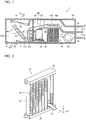
- Fig. 1 schematically illustrates a configuration of an air-conditioning apparatus according to Embodiment 1 of the present disclosure.
- an air-conditioning apparatus 1 includes a housing 90.
- the housing 90 has an indoor air inlet 91, an indoor air outlet 92, an outdoor air inlet 93, and an outdoor air outlet 94.
- the indoor air inlet 91 is an opening for suctioning indoor air A into the housing 90 from inside the room.
- the indoor air outlet 92 is an opening for blowing the indoor air A into the room.
- the outdoor air inlet 93 is an opening for suctioning outdoor air B into the housing 90 from outside the room.
- the outdoor air outlet 94 is an opening for blowing the outdoor air B to outside the room.
- a separation plate 95 separates the housing 90 into two spaces, in which a first air path 90a and a second air path 90b are formed.
- the indoor air A passes through the first air path 90a
- the outdoor air B passes through the second air path 90b. That is, the separation plate 95 separates the housing 90 into the space that communicates with the indoor air inlet 91 and the indoor air outlet 92 and the space that communicates with the outdoor air inlet 93 and the outdoor air outlet 94.
- the air-conditioning apparatus 1 includes a refrigerant circuit 10.
- the refrigerant circuit 10 includes a compressor 20, an expansion valve 30, an evaporator 40, and a condenser 50.
- the compressor 20, the condenser 50, the expansion valve 30, and the evaporator 40 are connected to each other in sequence via refrigerant pipes 60 to form an annulus, which enables refrigerant to circulate.
- the refrigerant pipes 60 are made of, for example, aluminum.
- the evaporator 40 is disposed in the first air path 90a inside the housing 90.
- the evaporator 40 exchanges heat between the indoor air A and the refrigerant.
- the evaporator 40 includes heat transfer tubes 41 and fins 42 connected to the heat transfer 62 tubes 41.
- the refrigerant flows through the heat transfer tubes 41.
- Fig. 1 includes a side view of the evaporator 40.
- the heat transfer tubes 41 correspond to evaporator-side heat transfer tubes
- the fins 42 correspond to evaporator-side fins.
- each of the heat transfer tubes 41 has a refrigerant path.
- the heat transfer tubes 41 are, for example, circular tubes that are circular in a cross section perpendicular to the axis of the refrigerant path. It should be noted that the heat transfer tubes 41 are not limited to circular tubes and may be flat tubes that are flat in a cross section perpendicular to the axis of the refrigerant path.
- the fins 42 are, for example, plate fins. It should be noted that the fins 42 are not limited to plate fins and may be corrugated fins.
- the heat transfer tubes 41 and the fins 42, which form the evaporator 40, are made of aluminum.
- An indoor-air-sending device 70 is disposed in the first air path 90a.
- the indoor-air-sending device 70 suctions the indoor air A through the indoor air inlet 91 and blows the indoor air A into the room through the indoor air outlet 92.
- the indoor-air-sending device 70 is, for example, a propeller fan. It should be noted that the indoor-air-sending device 70 is not limited to a propeller fan and may be, for example, a cross-flow fan.
- an indoor-side drain pan 110 is disposed below the evaporator 40 and stores condensed water C generated at the evaporator 40.
- the condenser 50 is disposed in the second air path 90b.
- the condenser 50 exchanges heat between the outdoor air B and the refrigerant.
- the configuration of the condenser 50 is described later.
- An outdoor-air-sending device 80 is disposed in the second air path 90b.
- the outdoor-air-sending device 80 suctions the outdoor air B through the outdoor air inlet 93 and blows the outdoor air B to outside the room through the outdoor air outlet 94.
- the outdoor-air-sending device 80 is, for example, a sirocco fan. It should be noted that the outdoor-air-sending device 80 is not limited to a sirocco fan and may be, for example, a propeller fan.
- the first air path 90a and the second air path 90b in the housing 90 are adjacent to each other in the horizontal direction inside the housing 90. That is, the evaporator 40 and the condenser 50 are apart from each other in the horizontal direction inside the housing 90.
- the compressor 20 is disposed in the second air path 90b.
- the expansion valve 30 is disposed in the first air path 90a. It should be noted that the compressor 20 may be disposed in the second air path 90b.
- the expansion valve 30 may be disposed in the second air path 90b.
- the inside of the housing 90 accommodates the compressor 20, the expansion valve 30, the evaporator 40, and the condenser 50.
- the housing 90 has the first air path 90a, through which the indoor air A passes, and the second air path 90b, through which the outdoor air B passes. That is, the air-conditioning apparatus 1 is a unitary air-conditioning apparatus.
- the air-conditioning apparatus 1 includes a water sprinkler 100.
- the water sprinkler 100 includes a water pump 101, a water pipe 102, and a water-sprinkling portion 103.
- the water-sprinkling portion 103 is disposed above the condenser 50 inside the housing 90.
- the water pump 101 is disposed in the indoor-side drain pan 110.
- the water pipe 102 connects the water pump 101 and the water-sprinkling portion 103 to each other.
- the water pump 101 suctions the condensed water C stored in the indoor-side drain pan 110.
- the water pipe 102 allows the suctioned condensed water C to flow to the water-sprinkling portion 103.
- the water-sprinkling portion 103 sprinkles the condensed water C onto the condenser 50. That is, the water sprinkler 100 sprinkles the condensed water C generated at the evaporator 40 onto the condenser 50.
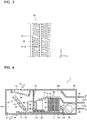
- Fig. 2 is a perspective view of the condenser of the air-conditioning apparatus according to Embodiment 1 of the present disclosure.
- the z-direction corresponds to the vertical direction.
- the x-direction is the direction in which the outdoor air B passes through the condenser 50.
- the y-direction is the direction perpendicular to the z-direction and the y-direction.
- the x-direction and the y-direction are parallel to a horizontal plane.
- the condenser 50 includes heat transfer tubes 51, fins 52, a first header 53, and a second header 54.
- the heat transfer tubes 51 are arranged parallel to each other and are arranged between the first header 53 and the second header 54.
- the heat transfer tubes 51 are disposed in such a manner that, for example, the longitudinal direction of the heat transfer tubes 51 is identical to the vertical direction.
- the inside of each of the heat transfer tubes 51 has a refrigerant path.
- the heat transfer tubes 51 are flat tubes that are flat in a cross section perpendicular to the axis of the refrigerant path.
- the heat transfer tubes 51 are disposed in such a manner that the long axis of the flat cross section is in the direction in which the outdoor air B flows.
- the first header 53 and the second header 54 are arranged parallel to each other.
- the first header 53 and the second header 54 are disposed in such a manner that, for example, the longitudinal direction of the first header 53 and the second header 54 is identical to the horizontal direction.
- the first header 53 is located higher than the second header 54.
- the first header 53 is connected to one end portion of each of the heat transfer tubes 51.
- the water sprinkler 100 sprinkles the condensed water C onto the top of the first header 53.
- the second header 54 is connected to the other end portion of each of the heat transfer tubes 51.
- the refrigerant that has flowed into the first header 53 diverges into streams, and the refrigerant streams then flow into the refrigerant paths of the heat transfer tubes 51.
- the refrigerant streams are mixed in the second header 54, and confluent refrigerant flows out from the second header 54.
- Each of the fins 52 is disposed between the heat transfer tubes 51.
- the fins 52 are, for example, corrugated fins.
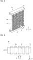
- Fig. 3 is a front view of a part of the condenser of the air-conditioning apparatus according to Embodiment 1 of the present disclosure.
- the heat transfer tubes 51 include a first heat transfer tube 51-1 and a second heat transfer tube 51-2.
- the first heat transfer tube 51-1 and the second heat transfer tube 51-2 are arranged adjacent and parallel to each other.
- the fin 52 is disposed between the first heat transfer tube 51-1 and the second heat transfer tube 51-2.
- the first header 53, the second header 54, the heat transfer tubes 51, and the fins 52, which form the condenser 50, are made of aluminum.
- the compressor 20 suctions low-temperature, low-pressure refrigerant and discharges high-temperature, high-pressure refrigerant.
- the high-temperature, high-pressure refrigerant discharged from the compressor 20 flows into the condenser 50.
- the refrigerant that has flowed into the condenser 50 exchanges heat with the outdoor air B sent from the outdoor-air-sending device 80 and rejects heat.
- the temperature of the refrigerant decreases, and the refrigerant becomes liquid-state refrigerant, which then flows out from the condenser 50.
- the expansion valve 30 reduces the pressure of the refrigerant that has flowed out from the condenser 50.
- the refrigerant becomes two-phase gas-liquid refrigerant, which then flows into the evaporator 40.
- the refrigerant that has flowed into the evaporator 40 exchanges heat with the indoor air A sent from the indoor-air-sending device 70.
- the refrigerant receives heat, evaporates, and becomes gas-state refrigerant, which then flows out from the evaporator 40.
- the compressor 20 suctions the refrigerant that has flowed out from the evaporator 40.
- the water sprinkler 100 When the indoor air A passes through the evaporator 40, moisture contained in the indoor air A condenses into the condensed water C.
- the condensed water C generated at the evaporator 40 is stored in the indoor-side drain pan 110 disposed below the evaporator 40.
- the water pump 101 suctions the condensed water C stored in the indoor-side drain pan 110.
- the water pipe 102 allows the suctioned condensed water C to flow to the water-sprinkling portion 103.
- the water-sprinkling portion 103 sprinkles the condensed water C onto the condenser 50.
- the water sprinkler 100 sprinkles the condensed water C onto the top of the first header 53.
- the water sprinkler 100 may include, for example, a water-level sensor for detecting the level of the condensed water C stored in the indoor-side drain pan 110. When the level of the condensed water C exceeds a predetermined level, the water pump 101 may be caused to operate.
- the condensed water C sprinkled on the top of the first header 53 flows out from the edges of the first header 53 and flows down along the surfaces of the heat transfer tubes 51 and the fins 52. That is, the condensed water C flows in the negative z-direction in Figs. 2 and 3 . After flowing out from the first header 53 to the fins 52, the condensed water C flows down along the surfaces of the fins 52.
- the condensed water C that has flowed out from the first header 53 to the fins 52 flows down, following the curves of the fins 52, which are corrugated fins. That is, the length of the route that the condensed water C flows along the surface of each of the fins 52 is more than the distance between the first header 53 and the second header 54.
- the condensed water C When flowing down along the surfaces of the heat transfer tubes 51 and the fins 52, the condensed water C is heated by the refrigerant in the heat transfer tubes 51 and thus evaporates into vapor.
- the air-conditioning apparatus 1 includes the evaporator 40, the condenser 50, and the water sprinkler 100.
- the evaporator 40 exchanges heat between the indoor air A and the refrigerant.
- the condenser 50 exchanges heat between the outdoor air B and the refrigerant.
- the water sprinkler 100 sprinkles the condensed water C generated at the evaporator 40 onto the condenser 50.
- the condenser 50 includes the first header 53, the second header 54, the heat transfer tubes 51, and the fins 52.
- the first header 53 and the second header 54 are arranged parallel to each other.
- the heat transfer tubes 51 are arranged parallel to each other and are arranged between the first header 53 and the second header 54.
- the fins 52 are disposed between the heat transfer tubes 51.
- the condensed water C sprinkled from the water sprinkler 100 onto the condenser 50 is easily retained on the surfaces of the fins 52 disposed between the heat transfer tubes 51.
- the air-conditioning apparatus 1 includes the water sprinkler 100.
- the air-conditioning apparatus 1 can sprinkle the condensed water C generated at the evaporator 40 onto the condenser 50.
- the first header 53 and the second header 54 extend in the horizontal direction, and the first header 53 is located higher than the second header 54.
- the water sprinkler 100 is configured to sprinkle the condensed water C onto the top of the first header 53.
- the condensed water C sprinkled on the top of the first header 53 flows down to the second header 54 along the surfaces of the heat transfer tubes 51 and the fins 52. That is, the condensed water C flows along the entire surface of the condenser 50, which makes it possible to increase the amount of the condensed water C to evaporate at the condenser 50.
- the fins 52 are corrugated fins.
- the condensed water C that has flowed out from the first header 53 to the fins 52 flows down, following the curves of the fins 52, which are corrugated fins. That is, the length of the route that the condensed water C flows along the surface of each of the fins 52 is more than the distance between the first header 53 and the second header 54.
- the duration for which the condensed water C receives heat from the fins 52 is longer, which facilitates evaporation of the condensed water C. Accordingly, it is possible to increase the amount of the condensed water C to evaporate at the condenser 50.
- the first header 53, the second header 54, the heat transfer tubes 51, and the fins 52, which form the condenser 50, are made of aluminum.
- the heat transfer tubes 41 and the fins 42, which form the evaporator 40 are made of aluminum.
- the evaporator 40 is copper or iron, it is possible to lighten the evaporator 40.
- the evaporator 40 is made of copper or iron, it is possible to more effectively prevent ions of a metal nobler than aluminum, such as copper ions, from dissolving into the condensed water C generated at the evaporator 40.
- ions of a metal nobler than aluminum such as copper ions
- the refrigerant pipes 60 are made of aluminum.
- the refrigerant pipes 60 are made of copper or iron, it is possible to lighten the evaporator 40.
- ions of a metal nobler than aluminum such as copper ions
- the evaporator 40, the condenser 50, and the refrigerant pipes 60 are made of aluminum, dissimilar metal welding is not necessary in the manufacturing of the refrigerant circuit 10, which enables manufacturability of the refrigerant circuit 10 to be improved.
- the condenser 50 includes the heat transfer tubes 51 arranged parallel to each other and arranged between the first header 53 and the second header 54.
- the configuration of the condenser in the present disclosure is not limited to the illustrated configuration.
- the condenser 50 may include, for example, circular tubes that are circular in a cross section perpendicular to the axis of a refrigerant path.
- the fins 52 are not limited to corrugated fins and may be plate fins.
- the water sprinkler 100 includes the water pump 101, the water pipe 102, and the water-sprinkling portion 103.
- the configuration of the water sprinkler 100 is not limited to the illustrated configuration. Any configuration is applicable as long as the water sprinkler 100 can sprinkle the condensed water C generated at the evaporator 40 onto the condenser 50.
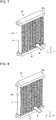
- Fig. 4 schematically illustrates a variation of the configuration of the air-conditioning apparatus according to Embodiment 1 of the present disclosure.
- an outdoor-side drain pan 120 is disposed below the condenser 50 inside the housing 90.
- a water pipe 121 connects the indoor-side drain pan 110 and the outdoor-side drain pan 120 to each other.
- the water pipe 121 allows the condensed water C stored in the indoor-side drain pan 110 to flow to the outdoor-side drain pan 120.
- the outdoor-side drain pan 120 stores the condensed water C generated at the evaporator 40.
- a water sprinkler 130 is disposed in the outdoor-side drain pan 120.
- the water sprinkler 130 is discoid, and the outer periphery of the water sprinkler 130 has blades for retaining the condensed water C.
- the water sprinkler 130 is driven by a driving unit such as a motor and rotates, which enables the blades on the outer periphery to splash and sprinkle the condensed water C stored in the outdoor-side drain pan 120 to a side face of the condenser 50.
- the condensed water C sprinkled from the water sprinkler 130 to the condenser 50 is retained on the fins 52, which makes it possible to increase the amount of the condensed water C to evaporate at the condenser 50.
- the water sprinkler 130 may be disposed upstream of the condenser 50 in the second air path 90b. This enables the condensed water C sprinkled by the water sprinkler 130 to flow with the outdoor air B, which ensures that the condensed water C adheres to the condenser 50.
- Embodiment 2 a configuration of an air-conditioning apparatus 1 in Embodiment 2 is described, focusing on differences from Embodiment 1. It should be noted that the same reference sign is assigned to an element identical to that described in Embodiment 1, and explanations for common elements are omitted.
- Fig. 5 is a perspective view of a condenser of an air-conditioning apparatus according to Embodiment 2 of the present disclosure.
- Fig. 6 is a top view of the condenser of the air-conditioning apparatus according to Embodiment 2 of the present disclosure.
- a condenser 50 includes fins 52a each disposed between heat transfer tubes 51.
- the fins 52a are, for example, corrugated fins.
- a water sprinkler 100 sprinkles condensed water C onto the top of a first header 53.
- each of the fins 52a protrude from the edges of the first header 53. That is, as illustrated in Fig. 6 , the length of each of the fins 52a in the x-direction is more than the length of the first header 53 in the x-direction.
- both end portions of each of the fins 52a protrude from the edges of the first header 53.
- the configuration of the condenser 50 is not limited to the illustrated configuration.
- One of the end portions of each of the fins 52a may protrude from the edge of the first header 53.
- Embodiment 2 when the condenser 50 is viewed from above, the end portions of each of the fins 52 protrude from the edges of the first header 53.
- Embodiment 3 a configuration of an air-conditioning apparatus 1 in Embodiment 3 is described, focusing on differences from Embodiments 1 and 2. It should be noted that the same reference sign is assigned to an element identical to that described in Embodiments 1 and 2, and explanations for common elements are omitted.
- Fig. 7 is a perspective view of a condenser of an air-conditioning apparatus according to Embodiment 3 of the present disclosure.
- the top of a first header 53a of a condenser 50 is a curved surface that protrudes upward from a horizontal plane. Specifically, regarding the protruded curved top of the first header 53a, in the direction in which outdoor air B flows, a center portion of the top protrudes upward, and end portions of the top are inclined downward. With such a configuration, condensed water C sprinkled on the top of the first header 53a flows down along the curved surface.
- both end portions of the top of the first header 53a are inclined downward toward both edges of the top.
- the shape of the top is not limited to the illustrated shape.
- the top of the first header 53a may be a curved surface having edges, one of which is inclined downward toward the other edge.
- the top of the first header 53a is a curved surface that protrudes upward from a horizontal plane.
- the condensed water C is less likely to be retained on the top of the first header 53a.
- the condensed water C sprinkled from the water sprinkler 100 onto the condenser 50 more easily reaches the fins 52.
- Fig. 8 is a perspective view of a variation of the condenser of the air-conditioning apparatus according to Embodiment 3 of the present disclosure.
- the top of a first header 53b of the condenser 50 is made of slopes and inclined to a horizontal plane. Specifically, in the direction in which the outdoor air B flows, the top of the first header 53b is inclined downward from the center, which is the apex of the top, toward both edges of the top. Hence, the top is made of the slopes. With such a shape of the top, the condensed water C sprinkled on the top of the first header 53b flows down along the slopes.
- the top of the first header 53b is inclined downward from the center toward both edges.
- the shape of the top is not limited to the illustrated shape.
- the top of the first header 53b may be a slope, that is, a surface with one edge higher than the other edge.
- the condensed water C is less likely to be retained on the top of the first header 53b.
- the condensed water C sprinkled from the water sprinkler 100 onto the condenser 50 more easily reaches the fins 52.
- Embodiment 4 a configuration of an air-conditioning apparatus 1 in Embodiment 4 is described, focusing on differences from Embodiments 1 to 3. It should be noted that the same reference sign is assigned to an element identical to that described in Embodiments 1 to 3, and explanations for common elements are omitted.
- Fig. 9 is a perspective view of a condenser of an air-conditioning apparatus according to Embodiment 4 of the present disclosure.
- Fig. 10 is a vertical cross-sectional view of the condenser of the air-conditioning apparatus according to Embodiment 4 of the present disclosure. It should be noted that Fig. 10 illustrates a cross section of a condenser 50 cut along the xy-plane.
- a second header 54a of the condenser 50 has a water-storage portion 56 that is a depression in the top of the second header 54a.
- a frame portion 55 protrudes upward from the top of the second header 54a, and the water-storage portion 56 is formed in the inside portion surrounded by the frame portion 55.
- a water sprinkler 100 sprinkles condensed water C onto the top of a first header 53.
- the condensed water C sprinkled on the top of the first header 53 flows out from the edges of the first header 53 and flows down along the surfaces of the heat transfer tubes 51 and fins 52.
- the condensed water C is heated by refrigerant in the heat transfer tubes 51 and evaporates into vapor.
- the condensed water C is stored in the water-storage portion 56 formed in the top of the second header 54a.
- the condensed water C stored in the water-storage portion 56 is heated by refrigerant in the second header 54a and evaporates into vapor.
- the vapor, together with the outdoor air B, passes through a second air path 90b and flows to outside a room through an outdoor air outlet 94.
- the second header 54a has the water-storage portion 56, which is a depression in the top of the second header 54a.
- the condensed water C stored in the water-storage portion 56 is heated by the refrigerant in the second header 54a to accelerate evaporation of the condensed water C.
- Embodiment 5 a configuration of an air-conditioning apparatus 1 in Embodiment 5 is described, focusing on differences from Embodiments 1 to 4. It should be noted that the same reference sign is assigned to an element identical to that described in Embodiments 1 to 4, and explanations for common elements are omitted.
- Fig. 11 schematically illustrates a configuration of an air-conditioning apparatus according to Embodiment 5 of the present disclosure.
- the air-conditioning apparatus 1 includes an ion-exchange resin 140.
- the ion-exchange resin 140 is configured to remove a metal that is nobler than aluminum and is contained in condensed water C generated at an evaporator 40. In an equilibrium reaction caused by ion exchange, the ion-exchange resin 140 exchanges a pre-absorbed ion for a target substance to absorb the target substance. For instance, as the target substance, the ion-exchange resin 140 absorbs copper ions contained in the condensed water C and removes the copper ions from the condensed water C.
- the ion-exchange resin 140 is disposed inside a water pipe 102.
- the ion-exchange resin 140 removes a metal nobler than aluminum from the condensed water C that passes through the water pipe 102. It should be noted that the position of the ion-exchange resin 140 is not limited to the illustrated position, and the ion-exchange resin 140 may be disposed in an indoor-side drain pan 110, a water pump 101, or a water-sprinkling portion 103.
- the air-conditioning apparatus 1 includes the ion-exchange resin 140 for removing a metal that is nobler than aluminum and is contained in the condensed water C generated at the evaporator 40.
- the ion-exchange resin 140 can remove ions of a metal nobler than aluminum, which makes it possible to decrease the amount of ions of the metal, which is nobler than aluminum, contained in the condensed water C. Accordingly, even when heat transfer tubes 41 and fins 42 of the condenser 50 are made of aluminum, it is possible to prevent galvanic corrosion in the condenser 50.
- the configuration of the water sprinkler 100 is not limited to the configuration illustrated in Fig. 11 . Any configuration is applicable as long as the water sprinkler 100 can sprinkle the condensed water C generated at the evaporator 40 onto the condenser 50. Moreover, changes can be made to the ion-exchange resin 140 as long as the ion-exchange resin 140 can remove a metal that is nobler than aluminum and is contained in the condensed water C, before the water sprinkler 100 sprinkles the condensed water C on the condenser 50.
- Fig. 12 schematically illustrates a variation of the configuration of the air-conditioning apparatus according to Embodiment 5 of the present disclosure.
- the ion-exchange resin 140 is added to the variation ( Fig. 4 ) of the configuration of the air-conditioning apparatus 1 described in Embodiment 1.
- the ion-exchange resin 140 is disposed in an outdoor-side drain pan 120.
- the ion-exchange resin 140 removes a metal nobler than aluminum from the condensed water C stored in the outdoor-side drain pan 120.
- the position of the ion-exchange resin 140 is not limited to the illustrated position, and the ion-exchange resin 140 may be disposed in the indoor-side drain pan 110, a water pipe 121, or a water sprinkler 130.
- the condenser 50 includes the first header 53 and the second header 54.
- the configuration of the condenser in the present disclosure is not limited to the illustrated configuration.
- the condenser 50 may be, for example, a serpentine heat exchanger made by bending a heat transfer tube into a serpentine tube.
- Embodiments 1 to 5 the air-conditioning apparatus 1 that performs a cooling operation to cool the indoor air A is described. However, the operation of the air-conditioning apparatus in the present disclosure is not limited to the cooling operation.
- the air-conditioning apparatus 1 may perform a dehumidifying operation to remove moisture contained in the indoor air A.
- refrigerant circuit 20 compressor 30 expansion valve 40 evaporator 41 heat transfer tube 42 fin 50 condenser 51 heat transfer tube 51-1 first heat transfer tube 51-2 second heat transfer tube 52 fin 52a fin 53 first header 53a first header 53b first header 54 second header 54a second header 55 frame portion 56 water-storage portion 60 refrigerant pipe 70 indoor-air-sending device 80 outdoor-air-sending device 90 housing 90a first air path 90b second air path 91 indoor air inlet 92 indoor air outlet 93 outdoor air inlet 94 outdoor air outlet 95 separation plate 100 water sprinkler 101 water pump 102 water pipe 103 water-sprinkling portion 110 indoor-side drain pan 120 outdoor-side drain pan 121 water pipe 130 water sprinkler 140 ion-exchange resin A indoor air B outdoor air C condensed water
Landscapes
- Engineering & Computer Science (AREA)
- Mechanical Engineering (AREA)
- General Engineering & Computer Science (AREA)
- Physics & Mathematics (AREA)
- Thermal Sciences (AREA)
- Chemical & Material Sciences (AREA)
- Combustion & Propulsion (AREA)
- Devices For Blowing Cold Air, Devices For Blowing Warm Air, And Means For Preventing Water Condensation In Air Conditioning Units (AREA)
- Air Filters, Heat-Exchange Apparatuses, And Housings Of Air-Conditioning Units (AREA)
Abstract
Description
- The present disclosure relates to an air-conditioning apparatus that has an evaporator and a condenser inside a housing.
- In some technology, a unitary cooling apparatus has been proposed in which an evaporator and a condenser are disposed on the same plane and the evaporator is located higher than the condenser (see, for example, Patent Literature 1). In the unitary cooling apparatus, the evaporator and the condenser are each made of a spine fin tube. The spine fin tube is made by fixing multiple rectangular spine fins to the outer periphery of a circular tube that is circular in cross section.
- Patent Literature 1: Japanese Unexamined Patent Application Publication No.
8-61699 - In the unitary cooling apparatus disclosed in Patent Literature 1, drain water (condensed water) drips from an evaporator onto a condenser, and the condensed water retained on the condenser evaporates with the heat of high-temperature refrigerant. However, in the unitary cooling apparatus disclosed in Patent Literature 1, the condenser is made of a spine fin tube, and thus it is difficult to retain the condensed water adhering to the spine fin tube. Thus, the amount of the condensed water to evaporate at the condenser is not sufficient, which is considered a problem.
- The present disclosure has been made to solve the above problem and aims to provide an air-conditioning apparatus with which it is possible to increase the amount of condensed water to evaporate at a condenser.
- An air-conditioning apparatus according to an embodiment of the present disclosure includes a housing having a first air path through which indoor air passes and a second air path through which outdoor air passes; an evaporator disposed in the first air path and configured to exchange heat between the indoor air and refrigerant; a condenser disposed in the second air path and configured to exchange heat between the outdoor air and the refrigerant; and a water sprinkler configured to sprinkle condensed water to the condenser, the condensed water being generated at the evaporator. The condenser includes a first heat transfer tube and a second heat transfer tube that are arranged parallel to each other, and a fin arranged between the first heat transfer tube and the second heat transfer tube.
- In the air-conditioning apparatus according to an embodiment of the present disclosure, the condenser includes the first heat transfer tube and the second heat transfer tube that are arranged parallel to each other, and the fin arranged between the first heat transfer tube and the second heat transfer tube. Thus, it is possible to increase the amount of condensed water to evaporate at the condenser.
-
- [
Fig. 1] Fig. 1 schematically illustrates a configuration of an air-conditioning apparatus according to Embodiment 1 of the present disclosure. - [
Fig. 2] Fig. 2 is a perspective view of a condenser of the air-conditioning apparatus according to Embodiment 1 of the present disclosure. - [
Fig. 3] Fig. 3 is a front view of a part of the condenser of the air-conditioning apparatus according to Embodiment 1 of the present disclosure. - [
Fig. 4] Fig. 4 schematically illustrates a variation of the configuration of the air-conditioning apparatus according to Embodiment 1 of the present disclosure. - [
Fig. 5] Fig. 5 is a perspective view of a condenser of an air-conditioning apparatus according to Embodiment 2 of the present disclosure. - [
Fig. 6] Fig. 6 is a top view of the condenser of the air-conditioning apparatus according to Embodiment 2 of the present disclosure. - [
Fig. 7] Fig. 7 is a perspective view of a condenser of an air-conditioning apparatus according to Embodiment 3 of the present disclosure. - [
Fig. 8] Fig. 8 is a perspective view of a variation of the condenser of the air-conditioning apparatus according to Embodiment 3 of the present disclosure. - [
Fig. 9] Fig. 9 is a perspective view of a condenser of an air-conditioning apparatus according to Embodiment 4 of the present disclosure. - [
Fig. 10] Fig. 10 is a vertical cross-sectional view of the condenser of the air-conditioning apparatus according to Embodiment 4 of the present disclosure. - [
Fig. 11] Fig. 11 schematically illustrates a configuration of an air-conditioning apparatus according to Embodiment 5 of the present disclosure. - [
Fig. 12] Fig. 12 schematically illustrates a variation of the configuration of the air-conditioning apparatus according to Embodiment 5 of the present disclosure. - Hereinafter, embodiments of the present disclosure are described with appropriate reference to the drawings. It should be noted that in the drawings referenced below and including
Fig. 1 , size relationships between structural elements may differ from actual ones. In addition, in the drawings referenced below and includingFig. 1 , structural elements illustrated with the same reference sign are the same or equivalent elements throughout the specification. Moreover, forms of the structural elements given throughout the specification are mere examples and are not limited to the given examples. -
Fig. 1 schematically illustrates a configuration of an air-conditioning apparatus according to Embodiment 1 of the present disclosure. - As illustrated in
Fig. 1 , an air-conditioning apparatus 1 includes ahousing 90. Thehousing 90 has anindoor air inlet 91, anindoor air outlet 92, anoutdoor air inlet 93, and anoutdoor air outlet 94. Theindoor air inlet 91 is an opening for suctioning indoor air A into thehousing 90 from inside the room. Theindoor air outlet 92 is an opening for blowing the indoor air A into the room. Theoutdoor air inlet 93 is an opening for suctioning outdoor air B into thehousing 90 from outside the room. Theoutdoor air outlet 94 is an opening for blowing the outdoor air B to outside the room. - A
separation plate 95 separates thehousing 90 into two spaces, in which afirst air path 90a and asecond air path 90b are formed. The indoor air A passes through thefirst air path 90a, and the outdoor air B passes through thesecond air path 90b. That is, theseparation plate 95 separates thehousing 90 into the space that communicates with theindoor air inlet 91 and theindoor air outlet 92 and the space that communicates with theoutdoor air inlet 93 and theoutdoor air outlet 94. - The air-conditioning apparatus 1 includes a
refrigerant circuit 10. Therefrigerant circuit 10 includes acompressor 20, anexpansion valve 30, anevaporator 40, and acondenser 50. Thecompressor 20, thecondenser 50, theexpansion valve 30, and theevaporator 40 are connected to each other in sequence viarefrigerant pipes 60 to form an annulus, which enables refrigerant to circulate. Therefrigerant pipes 60 are made of, for example, aluminum. - The
evaporator 40 is disposed in thefirst air path 90a inside thehousing 90. Theevaporator 40 exchanges heat between the indoor air A and the refrigerant. Theevaporator 40 includesheat transfer tubes 41 andfins 42 connected to the heat transfer 62tubes 41. The refrigerant flows through theheat transfer tubes 41. It should be noted thatFig. 1 includes a side view of theevaporator 40. Theheat transfer tubes 41 correspond to evaporator-side heat transfer tubes, and thefins 42 correspond to evaporator-side fins. - The inside of each of the
heat transfer tubes 41 has a refrigerant path. Theheat transfer tubes 41 are, for example, circular tubes that are circular in a cross section perpendicular to the axis of the refrigerant path. It should be noted that theheat transfer tubes 41 are not limited to circular tubes and may be flat tubes that are flat in a cross section perpendicular to the axis of the refrigerant path. - The fins 42 are, for example, plate fins. It should be noted that the
fins 42 are not limited to plate fins and may be corrugated fins. - The
heat transfer tubes 41 and thefins 42, which form theevaporator 40, are made of aluminum. - An indoor-air-sending
device 70 is disposed in thefirst air path 90a. The indoor-air-sendingdevice 70 suctions the indoor air A through theindoor air inlet 91 and blows the indoor air A into the room through theindoor air outlet 92. The indoor-air-sendingdevice 70 is, for example, a propeller fan. It should be noted that the indoor-air-sendingdevice 70 is not limited to a propeller fan and may be, for example, a cross-flow fan. - Inside the
housing 90, an indoor-side drain pan 110 is disposed below theevaporator 40 and stores condensed water C generated at theevaporator 40. - The
condenser 50 is disposed in thesecond air path 90b. Thecondenser 50 exchanges heat between the outdoor air B and the refrigerant. The configuration of thecondenser 50 is described later. - An outdoor-air-sending
device 80 is disposed in thesecond air path 90b. The outdoor-air-sendingdevice 80 suctions the outdoor air B through theoutdoor air inlet 93 and blows the outdoor air B to outside the room through theoutdoor air outlet 94. The outdoor-air-sendingdevice 80 is, for example, a sirocco fan. It should be noted that the outdoor-air-sendingdevice 80 is not limited to a sirocco fan and may be, for example, a propeller fan. - The
first air path 90a and thesecond air path 90b in thehousing 90 are adjacent to each other in the horizontal direction inside thehousing 90. That is, theevaporator 40 and thecondenser 50 are apart from each other in the horizontal direction inside thehousing 90. - The
compressor 20 is disposed in thesecond air path 90b. Theexpansion valve 30 is disposed in thefirst air path 90a. It should be noted that thecompressor 20 may be disposed in thesecond air path 90b. Theexpansion valve 30 may be disposed in thesecond air path 90b. - The inside of the
housing 90 accommodates thecompressor 20, theexpansion valve 30, theevaporator 40, and thecondenser 50. In the air-conditioning apparatus 1, thehousing 90 has thefirst air path 90a, through which the indoor air A passes, and thesecond air path 90b, through which the outdoor air B passes. That is, the air-conditioning apparatus 1 is a unitary air-conditioning apparatus. - The air-conditioning apparatus 1 includes a
water sprinkler 100. Thewater sprinkler 100 includes awater pump 101, awater pipe 102, and a water-sprinklingportion 103. The water-sprinklingportion 103 is disposed above thecondenser 50 inside thehousing 90. Thewater pump 101 is disposed in the indoor-side drain pan 110. Thewater pipe 102 connects thewater pump 101 and the water-sprinklingportion 103 to each other. With thewater sprinkler 100, thewater pump 101 suctions the condensed water C stored in the indoor-side drain pan 110. Then, thewater pipe 102 allows the suctioned condensed water C to flow to the water-sprinklingportion 103. The water-sprinklingportion 103 sprinkles the condensed water C onto thecondenser 50. That is, thewater sprinkler 100 sprinkles the condensed water C generated at theevaporator 40 onto thecondenser 50. -
Fig. 2 is a perspective view of the condenser of the air-conditioning apparatus according to Embodiment 1 of the present disclosure. - It should be noted that in
Fig. 2 , the z-direction corresponds to the vertical direction. The x-direction is the direction in which the outdoor air B passes through thecondenser 50. The y-direction is the direction perpendicular to the z-direction and the y-direction. The x-direction and the y-direction are parallel to a horizontal plane. - As illustrated in
Fig. 2 , thecondenser 50 includesheat transfer tubes 51,fins 52, afirst header 53, and asecond header 54. - The
heat transfer tubes 51 are arranged parallel to each other and are arranged between thefirst header 53 and thesecond header 54. Theheat transfer tubes 51 are disposed in such a manner that, for example, the longitudinal direction of theheat transfer tubes 51 is identical to the vertical direction. The inside of each of theheat transfer tubes 51 has a refrigerant path. Theheat transfer tubes 51 are flat tubes that are flat in a cross section perpendicular to the axis of the refrigerant path. Theheat transfer tubes 51 are disposed in such a manner that the long axis of the flat cross section is in the direction in which the outdoor air B flows. - The
first header 53 and thesecond header 54 are arranged parallel to each other. Thefirst header 53 and thesecond header 54 are disposed in such a manner that, for example, the longitudinal direction of thefirst header 53 and thesecond header 54 is identical to the horizontal direction. Thefirst header 53 is located higher than thesecond header 54. Thefirst header 53 is connected to one end portion of each of theheat transfer tubes 51. Moreover, thewater sprinkler 100 sprinkles the condensed water C onto the top of thefirst header 53. Thesecond header 54 is connected to the other end portion of each of theheat transfer tubes 51. The refrigerant that has flowed into thefirst header 53 diverges into streams, and the refrigerant streams then flow into the refrigerant paths of theheat transfer tubes 51. The refrigerant streams are mixed in thesecond header 54, and confluent refrigerant flows out from thesecond header 54. - Each of the
fins 52 is disposed between theheat transfer tubes 51. Thefins 52 are, for example, corrugated fins. -
Fig. 3 is a front view of a part of the condenser of the air-conditioning apparatus according to Embodiment 1 of the present disclosure. - As illustrated in
Fig. 3 , theheat transfer tubes 51 include a first heat transfer tube 51-1 and a second heat transfer tube 51-2. The first heat transfer tube 51-1 and the second heat transfer tube 51-2 are arranged adjacent and parallel to each other. Thefin 52 is disposed between the first heat transfer tube 51-1 and the second heat transfer tube 51-2. - The
first header 53, thesecond header 54, theheat transfer tubes 51, and thefins 52, which form thecondenser 50, are made of aluminum. - Hereinafter, operation of the air-conditioning apparatus 1 is described.
- When a cooling operation starts, the
compressor 20, the indoor-air-sendingdevice 70, and the outdoor-air-sendingdevice 80 start operating. Thecompressor 20 suctions low-temperature, low-pressure refrigerant and discharges high-temperature, high-pressure refrigerant. The high-temperature, high-pressure refrigerant discharged from thecompressor 20 flows into thecondenser 50. Then, the refrigerant that has flowed into thecondenser 50 exchanges heat with the outdoor air B sent from the outdoor-air-sendingdevice 80 and rejects heat. Thus, the temperature of the refrigerant decreases, and the refrigerant becomes liquid-state refrigerant, which then flows out from thecondenser 50. Theexpansion valve 30 reduces the pressure of the refrigerant that has flowed out from thecondenser 50. The refrigerant becomes two-phase gas-liquid refrigerant, which then flows into theevaporator 40. The refrigerant that has flowed into theevaporator 40 exchanges heat with the indoor air A sent from the indoor-air-sendingdevice 70. The refrigerant receives heat, evaporates, and becomes gas-state refrigerant, which then flows out from theevaporator 40. Thecompressor 20 suctions the refrigerant that has flowed out from theevaporator 40. - When the indoor air A passes through the
evaporator 40, moisture contained in the indoor air A condenses into the condensed water C. The condensed water C generated at theevaporator 40 is stored in the indoor-side drain pan 110 disposed below theevaporator 40. In thewater sprinkler 100, thewater pump 101 suctions the condensed water C stored in the indoor-side drain pan 110. Then, thewater pipe 102 allows the suctioned condensed water C to flow to the water-sprinklingportion 103. The water-sprinklingportion 103 sprinkles the condensed water C onto thecondenser 50. Specifically, thewater sprinkler 100 sprinkles the condensed water C onto the top of thefirst header 53. - It should be noted that the
water sprinkler 100 may include, for example, a water-level sensor for detecting the level of the condensed water C stored in the indoor-side drain pan 110. When the level of the condensed water C exceeds a predetermined level, thewater pump 101 may be caused to operate. - The condensed water C sprinkled on the top of the
first header 53 flows out from the edges of thefirst header 53 and flows down along the surfaces of theheat transfer tubes 51 and thefins 52. That is, the condensed water C flows in the negative z-direction inFigs. 2 and3 . After flowing out from thefirst header 53 to thefins 52, the condensed water C flows down along the surfaces of thefins 52. - When the
fins 52 are corrugated fins, the condensed water C that has flowed out from thefirst header 53 to thefins 52 flows down, following the curves of thefins 52, which are corrugated fins. That is, the length of the route that the condensed water C flows along the surface of each of thefins 52 is more than the distance between thefirst header 53 and thesecond header 54. - When flowing down along the surfaces of the
heat transfer tubes 51 and thefins 52, the condensed water C is heated by the refrigerant in theheat transfer tubes 51 and thus evaporates into vapor. The vapor, together with the outdoor air B, passes through thesecond air path 90b and flows to outside the room through theoutdoor air outlet 94. - As described above, in Embodiment 1, the air-conditioning apparatus 1 includes the
evaporator 40, thecondenser 50, and thewater sprinkler 100. Theevaporator 40 exchanges heat between the indoor air A and the refrigerant. Thecondenser 50 exchanges heat between the outdoor air B and the refrigerant. Thewater sprinkler 100 sprinkles the condensed water C generated at theevaporator 40 onto thecondenser 50. Thecondenser 50 includes thefirst header 53, thesecond header 54, theheat transfer tubes 51, and thefins 52. Thefirst header 53 and thesecond header 54 are arranged parallel to each other. Theheat transfer tubes 51 are arranged parallel to each other and are arranged between thefirst header 53 and thesecond header 54. Thefins 52 are disposed between theheat transfer tubes 51. - Thus, the condensed water C sprinkled from the
water sprinkler 100 onto thecondenser 50 is easily retained on the surfaces of thefins 52 disposed between theheat transfer tubes 51. Thus, it is possible to increase the amount of the condensed water C to evaporate at thecondenser 50. In addition, the air-conditioning apparatus 1 includes thewater sprinkler 100. Thus, even when theevaporator 40 and thecondenser 50 are apart from each other in the horizontal direction, the air-conditioning apparatus 1 can sprinkle the condensed water C generated at theevaporator 40 onto thecondenser 50. Thus, it is possible to more flexibly determine the positional relationship between the evaporator 40 and thecondenser 50 inside thehousing 90. - In Embodiment 1, the
first header 53 and thesecond header 54 extend in the horizontal direction, and thefirst header 53 is located higher than thesecond header 54. Thewater sprinkler 100 is configured to sprinkle the condensed water C onto the top of thefirst header 53. - Thus, the condensed water C sprinkled on the top of the
first header 53 flows down to thesecond header 54 along the surfaces of theheat transfer tubes 51 and thefins 52. That is, the condensed water C flows along the entire surface of thecondenser 50, which makes it possible to increase the amount of the condensed water C to evaporate at thecondenser 50. - Moreover, in Embodiment 1, the
fins 52 are corrugated fins. - Thus, the condensed water C that has flowed out from the
first header 53 to thefins 52 flows down, following the curves of thefins 52, which are corrugated fins. That is, the length of the route that the condensed water C flows along the surface of each of thefins 52 is more than the distance between thefirst header 53 and thesecond header 54. Thus, compared with when thefins 52 are plate fins, the duration for which the condensed water C receives heat from thefins 52 is longer, which facilitates evaporation of the condensed water C. Accordingly, it is possible to increase the amount of the condensed water C to evaporate at thecondenser 50. - Moreover, in Embodiment 1, the
first header 53, thesecond header 54, theheat transfer tubes 51, and thefins 52, which form thecondenser 50, are made of aluminum. - Thus, compared with when the
condenser 50 is copper or iron, it is possible to lighten thecondenser 50. - Moreover, in Embodiment 1, the
heat transfer tubes 41 and thefins 42, which form theevaporator 40, are made of aluminum. - Thus, compared with when the
evaporator 40 is copper or iron, it is possible to lighten theevaporator 40. In addition, compared with when theevaporator 40 is made of copper or iron, it is possible to more effectively prevent ions of a metal nobler than aluminum, such as copper ions, from dissolving into the condensed water C generated at theevaporator 40. Thus, it is possible to prevent galvanic corrosion in thecondenser 50 that may occur when the condensed water C generated at theevaporator 40 is sprinkled onto thecondenser 50 made of aluminum. - In Embodiment 1, the
refrigerant pipes 60 are made of aluminum. - Thus, compared with when the
refrigerant pipes 60 are made of copper or iron, it is possible to lighten theevaporator 40. In addition, compared with when therefrigerant pipes 60 are made of copper or iron, it is possible to more effectively prevent ions of a metal nobler than aluminum, such as copper ions, from dissolving into the condensed water C generated at theevaporator 40. Thus, it is possible to prevent galvanic corrosion in thecondenser 50 that may occur when the condensed water C generated at theevaporator 40 is sprinkled onto thecondenser 50 made of aluminum. - Moreover, when the
evaporator 40, thecondenser 50, and therefrigerant pipes 60 are made of aluminum, dissimilar metal welding is not necessary in the manufacturing of therefrigerant circuit 10, which enables manufacturability of therefrigerant circuit 10 to be improved. - It should be noted that in Embodiment 1, the
condenser 50 includes theheat transfer tubes 51 arranged parallel to each other and arranged between thefirst header 53 and thesecond header 54. However, the configuration of the condenser in the present disclosure is not limited to the illustrated configuration. Instead of theheat transfer tubes 51, thecondenser 50 may include, for example, circular tubes that are circular in a cross section perpendicular to the axis of a refrigerant path. Moreover, thefins 52 are not limited to corrugated fins and may be plate fins. - Even with such a configuration, it is possible to increase the amount of the condensed water C to evaporate at the
condenser 50. - In the above description, the
water sprinkler 100 includes thewater pump 101, thewater pipe 102, and the water-sprinklingportion 103. However, the configuration of thewater sprinkler 100 is not limited to the illustrated configuration. Any configuration is applicable as long as thewater sprinkler 100 can sprinkle the condensed water C generated at theevaporator 40 onto thecondenser 50. -
Fig. 4 schematically illustrates a variation of the configuration of the air-conditioning apparatus according to Embodiment 1 of the present disclosure. - As illustrated in
Fig. 4 , an outdoor-side drain pan 120 is disposed below thecondenser 50 inside thehousing 90. Awater pipe 121 connects the indoor-side drain pan 110 and the outdoor-side drain pan 120 to each other. Thewater pipe 121 allows the condensed water C stored in the indoor-side drain pan 110 to flow to the outdoor-side drain pan 120. The outdoor-side drain pan 120 stores the condensed water C generated at theevaporator 40. Awater sprinkler 130 is disposed in the outdoor-side drain pan 120. - The
water sprinkler 130 is discoid, and the outer periphery of thewater sprinkler 130 has blades for retaining the condensed water C. Thewater sprinkler 130 is driven by a driving unit such as a motor and rotates, which enables the blades on the outer periphery to splash and sprinkle the condensed water C stored in the outdoor-side drain pan 120 to a side face of thecondenser 50. - Even with such a configuration, the condensed water C sprinkled from the
water sprinkler 130 to thecondenser 50 is retained on thefins 52, which makes it possible to increase the amount of the condensed water C to evaporate at thecondenser 50. - It should be noted that the
water sprinkler 130 may be disposed upstream of thecondenser 50 in thesecond air path 90b. This enables the condensed water C sprinkled by thewater sprinkler 130 to flow with the outdoor air B, which ensures that the condensed water C adheres to thecondenser 50. - Hereinafter, a configuration of an air-conditioning apparatus 1 in Embodiment 2 is described, focusing on differences from Embodiment 1. It should be noted that the same reference sign is assigned to an element identical to that described in Embodiment 1, and explanations for common elements are omitted.
-
Fig. 5 is a perspective view of a condenser of an air-conditioning apparatus according to Embodiment 2 of the present disclosure. -
Fig. 6 is a top view of the condenser of the air-conditioning apparatus according to Embodiment 2 of the present disclosure. - As illustrated in
Figs. 5 and 6 , acondenser 50 includesfins 52a each disposed betweenheat transfer tubes 51. Thefins 52a are, for example, corrugated fins. Awater sprinkler 100 sprinkles condensed water C onto the top of afirst header 53. - When the
condenser 50 is viewed from above, the end portions of each of thefins 52a protrude from the edges of thefirst header 53. That is, as illustrated inFig. 6 , the length of each of thefins 52a in the x-direction is more than the length of thefirst header 53 in the x-direction. - It should be noted that in the example illustrated in
Fig. 6 , both end portions of each of thefins 52a protrude from the edges of thefirst header 53. However, the configuration of thecondenser 50 is not limited to the illustrated configuration. One of the end portions of each of thefins 52a may protrude from the edge of thefirst header 53. - As described above, in Embodiment 2, when the
condenser 50 is viewed from above, the end portions of each of thefins 52 protrude from the edges of thefirst header 53. - This facilitates adhesion of the condensed water C to the surfaces of the
fins 52a when the condensed water C sprinkled on the top of thefirst header 53 flows out from the edges of thefirst header 53 and flows down along the surfaces of thefins 52a. Thus, the condensed water C sprinkled from thewater sprinkler 100 onto thecondenser 50 is easily retained on the surfaces of thefins 52a. Thus, it is possible to increase the amount of the condensed water C to evaporate at thecondenser 50. - Hereinafter, a configuration of an air-conditioning apparatus 1 in Embodiment 3 is described, focusing on differences from Embodiments 1 and 2. It should be noted that the same reference sign is assigned to an element identical to that described in Embodiments 1 and 2, and explanations for common elements are omitted.
-
Fig. 7 is a perspective view of a condenser of an air-conditioning apparatus according to Embodiment 3 of the present disclosure. - As illustrated in
Fig. 7 , the top of afirst header 53a of acondenser 50 is a curved surface that protrudes upward from a horizontal plane. Specifically, regarding the protruded curved top of thefirst header 53a, in the direction in which outdoor air B flows, a center portion of the top protrudes upward, and end portions of the top are inclined downward. With such a configuration, condensed water C sprinkled on the top of thefirst header 53a flows down along the curved surface. - It should be noted that in the example illustrated in
Fig. 7 , in the curved surface, both end portions of the top of thefirst header 53a are inclined downward toward both edges of the top. However, the shape of the top is not limited to the illustrated shape. The top of thefirst header 53a may be a curved surface having edges, one of which is inclined downward toward the other edge. - As described above, in Embodiment 3, the top of the
first header 53a is a curved surface that protrudes upward from a horizontal plane. - Thus, even when the condensed water C is sprinkled from above the
condenser 50, the condensed water C is less likely to be retained on the top of thefirst header 53a. Thus, the condensed water C sprinkled from thewater sprinkler 100 onto thecondenser 50 more easily reaches thefins 52. Thus, it is possible to increase the amount of the condensed water C to evaporate at thecondenser 50. -
Fig. 8 is a perspective view of a variation of the condenser of the air-conditioning apparatus according to Embodiment 3 of the present disclosure. - As illustrated in
Fig. 8 , the top of afirst header 53b of thecondenser 50 is made of slopes and inclined to a horizontal plane. Specifically, in the direction in which the outdoor air B flows, the top of thefirst header 53b is inclined downward from the center, which is the apex of the top, toward both edges of the top. Hence, the top is made of the slopes. With such a shape of the top, the condensed water C sprinkled on the top of thefirst header 53b flows down along the slopes. - It should be noted that in the example illustrated in
Fig. 8 , the top of thefirst header 53b is inclined downward from the center toward both edges. However, the shape of the top is not limited to the illustrated shape. The top of thefirst header 53b may be a slope, that is, a surface with one edge higher than the other edge. - Even with such a slope, the condensed water C is less likely to be retained on the top of the
first header 53b. Thus, the condensed water C sprinkled from thewater sprinkler 100 onto thecondenser 50 more easily reaches thefins 52. Thus, it is possible to increase the amount of the condensed water C to evaporate at thecondenser 50. - Hereinafter, a configuration of an air-conditioning apparatus 1 in Embodiment 4 is described, focusing on differences from Embodiments 1 to 3. It should be noted that the same reference sign is assigned to an element identical to that described in Embodiments 1 to 3, and explanations for common elements are omitted.
-
Fig. 9 is a perspective view of a condenser of an air-conditioning apparatus according to Embodiment 4 of the present disclosure. -
Fig. 10 is a vertical cross-sectional view of the condenser of the air-conditioning apparatus according to Embodiment 4 of the present disclosure. It should be noted thatFig. 10 illustrates a cross section of acondenser 50 cut along the xy-plane. - As illustrated in
Figs. 9 and 10 , asecond header 54a of thecondenser 50 has a water-storage portion 56 that is a depression in the top of thesecond header 54a. Specifically, aframe portion 55 protrudes upward from the top of thesecond header 54a, and the water-storage portion 56 is formed in the inside portion surrounded by theframe portion 55. - A
water sprinkler 100 sprinkles condensed water C onto the top of afirst header 53. The condensed water C sprinkled on the top of thefirst header 53 flows out from the edges of thefirst header 53 and flows down along the surfaces of theheat transfer tubes 51 andfins 52. When flowing down along the surfaces of theheat transfer tubes 51 and thefins 52, the condensed water C is heated by refrigerant in theheat transfer tubes 51 and evaporates into vapor. When a portion of the condensed water C reaches thesecond header 54a without evaporating, the condensed water C is stored in the water-storage portion 56 formed in the top of thesecond header 54a. The condensed water C stored in the water-storage portion 56 is heated by refrigerant in thesecond header 54a and evaporates into vapor. The vapor, together with the outdoor air B, passes through asecond air path 90b and flows to outside a room through anoutdoor air outlet 94. - As described above, in Embodiment 4, the
second header 54a has the water-storage portion 56, which is a depression in the top of thesecond header 54a. - Thus, even when a portion of the condensed water C reaches the
second header 54a without evaporating, it is possible to prevent the condensed water C from flowing out from and below thecondenser 50. Moreover, the condensed water C stored in the water-storage portion 56 is heated by the refrigerant in thesecond header 54a to accelerate evaporation of the condensed water C. Thus, it is possible to increase the amount of the condensed water C to evaporate at thecondenser 50. - Furthermore, it is not necessary to provide a drain pan that is a separate component from the
condenser 50 to store the condensed water C that flows out from and below thecondenser 50. Thus, it is possible to reduce the number of components. - Hereinafter, a configuration of an air-conditioning apparatus 1 in Embodiment 5 is described, focusing on differences from Embodiments 1 to 4. It should be noted that the same reference sign is assigned to an element identical to that described in Embodiments 1 to 4, and explanations for common elements are omitted.
-
Fig. 11 schematically illustrates a configuration of an air-conditioning apparatus according to Embodiment 5 of the present disclosure. - As illustrated in
Fig. 11 , the air-conditioning apparatus 1 includes an ion-exchange resin 140. The ion-exchange resin 140 is configured to remove a metal that is nobler than aluminum and is contained in condensed water C generated at anevaporator 40. In an equilibrium reaction caused by ion exchange, the ion-exchange resin 140 exchanges a pre-absorbed ion for a target substance to absorb the target substance. For instance, as the target substance, the ion-exchange resin 140 absorbs copper ions contained in the condensed water C and removes the copper ions from the condensed water C. - The ion-
exchange resin 140 is disposed inside awater pipe 102. The ion-exchange resin 140 removes a metal nobler than aluminum from the condensed water C that passes through thewater pipe 102. It should be noted that the position of the ion-exchange resin 140 is not limited to the illustrated position, and the ion-exchange resin 140 may be disposed in an indoor-side drain pan 110, awater pump 101, or a water-sprinklingportion 103. - As described above, in Embodiment 5, the air-conditioning apparatus 1 includes the ion-
exchange resin 140 for removing a metal that is nobler than aluminum and is contained in the condensed water C generated at theevaporator 40. - Thus, before the condensed water C is sprinkled on a
condenser 50, the ion-exchange resin 140 can remove ions of a metal nobler than aluminum, which makes it possible to decrease the amount of ions of the metal, which is nobler than aluminum, contained in the condensed water C. Accordingly, even whenheat transfer tubes 41 andfins 42 of thecondenser 50 are made of aluminum, it is possible to prevent galvanic corrosion in thecondenser 50. - The configuration of the
water sprinkler 100 is not limited to the configuration illustrated inFig. 11 . Any configuration is applicable as long as thewater sprinkler 100 can sprinkle the condensed water C generated at theevaporator 40 onto thecondenser 50. Moreover, changes can be made to the ion-exchange resin 140 as long as the ion-exchange resin 140 can remove a metal that is nobler than aluminum and is contained in the condensed water C, before thewater sprinkler 100 sprinkles the condensed water C on thecondenser 50. -
Fig. 12 schematically illustrates a variation of the configuration of the air-conditioning apparatus according to Embodiment 5 of the present disclosure. - In the air-conditioning apparatus 1 in the variation, the ion-
exchange resin 140 is added to the variation (Fig. 4 ) of the configuration of the air-conditioning apparatus 1 described in Embodiment 1. - As illustrated in
Fig. 12 , the ion-exchange resin 140 is disposed in an outdoor-side drain pan 120. The ion-exchange resin 140 removes a metal nobler than aluminum from the condensed water C stored in the outdoor-side drain pan 120. It should be noted that the position of the ion-exchange resin 140 is not limited to the illustrated position, and the ion-exchange resin 140 may be disposed in the indoor-side drain pan 110, awater pipe 121, or awater sprinkler 130. - Even with such a configuration, it is possible to decrease the amount of ions of the metal, which is nobler than aluminum, contained in the condensed water C. Accordingly, even when the
heat transfer tubes 41 and thefins 42 of thecondenser 50 are made of aluminum, it is possible to prevent galvanic corrosion in thecondenser 50. - It should be noted that in Embodiments 1 to 5, the
condenser 50 includes thefirst header 53 and thesecond header 54. However, the configuration of the condenser in the present disclosure is not limited to the illustrated configuration. Thecondenser 50 may be, for example, a serpentine heat exchanger made by bending a heat transfer tube into a serpentine tube. - It should be noted that in Embodiments 1 to 5, the air-conditioning apparatus 1 that performs a cooling operation to cool the indoor air A is described. However, the operation of the air-conditioning apparatus in the present disclosure is not limited to the cooling operation. By causing the
evaporator 40 to cool the indoor air A, the air-conditioning apparatus 1 may perform a dehumidifying operation to remove moisture contained in the indoor air A. - 1 air-
conditioning apparatus 10refrigerant circuit 20compressor 30expansion valve 40evaporator 41heat transfer tube 42fin 50condenser 51 heat transfer tube 51-1 first heat transfer tube 51-2 secondheat transfer tube 52fin 52a finfirst header 53afirst header 53bfirst header 54second header 54asecond header 55frame portion 56 water-storage portion 60refrigerant pipe 70 indoor-air-sendingdevice 80 outdoor-air-sendingdevice 90housing 90afirst air path 90bsecond air path 91indoor air inlet 92indoor air outlet 93outdoor air inlet 94outdoor air outlet 95separation plate 100water sprinkler 101water pump 102water pipe 103 water-sprinklingportion 110 indoor-side drain pan 120 outdoor-side drain pan 121water pipe 130water sprinkler 140 ion-exchange resin A indoor air B outdoor air C condensed water
Claims (11)
- An air-conditioning apparatus, comprising:a housing having a first air path through which indoor air passes and a second air path through which outdoor air passes;an evaporator disposed in the first air path and configured to exchange heat between the indoor air and refrigerant;a condenser disposed in the second air path and configured to exchange heat between the outdoor air and the refrigerant; anda water sprinkler configured to sprinkle condensed water to the condenser, the condensed water being generated at the evaporator,the condenser includinga first heat transfer tube and a second heat transfer tube that are arranged parallel to each other, anda fin arranged between the first heat transfer tube and the second heat transfer tube.
- The air-conditioning apparatus of claim 1,
wherein the condenser includes a first header and a second header arranged parallel to each other, and
the first heat transfer tube and the second heat transfer tube are arranged parallel to each other and are arranged between the first header and the second header. - The air-conditioning apparatus of claim 2,
wherein the first header and the second header extend in a horizontal direction,
the first header is located higher than the second header, and
the water sprinkler is configured to sprinkle the condensed water onto a top of the first header. - The air-conditioning apparatus of claim 2 or 3,
wherein, when the condenser is viewed from above, an end portion of the fin protrudes from an edge of the first header. - The air-conditioning apparatus of any one of claims 2 to 4,
wherein a top of the first header is a slope inclined to a horizontal plane or a curved surface that protrudes upward from the horizontal plane. - The air-conditioning apparatus of any one of claims 2 to 5,
wherein the second header has a water-storage portion that is a depression in a top of the second header. - The air-conditioning apparatus of any one of claims 2 to 6,
wherein the first header, the second header, the first heat transfer tube, the second heat transfer tube, and the fin are made of aluminum. - The air-conditioning apparatus of any one of claims 1 to 7,
wherein the fin is a corrugated fin. - The air-conditioning apparatus of any one of claims 1 to 8,
wherein the evaporator includes
a plurality of evaporator-side heat transfer tubes through which the refrigerant flows, and
a plurality of evaporator-side fins connected to the plurality of evaporator-side heat transfer tubes, and
the plurality of evaporator-side heat transfer tubes and the plurality of evaporator-side fins are made of aluminum. - The air-conditioning apparatus of any one of claims 1 to 9, comprising
a refrigerant circuit in which a compressor, the condenser, an expansion valve, and the evaporator are connected to each other via refrigerant pipes to enable the refrigerant to circulate,
wherein the refrigerant pipes are made of aluminum. - The air-conditioning apparatus of any one of claims 1 to 10, comprising
an ion-exchange resin for removing a metal that is nobler than aluminum and is contained in the condensed water generated at the evaporator.
Applications Claiming Priority (1)
| Application Number | Priority Date | Filing Date | Title |
|---|---|---|---|
| PCT/JP2018/015224 WO2019198174A1 (en) | 2018-04-11 | 2018-04-11 | Air conditioning device |
Publications (2)
| Publication Number | Publication Date |
|---|---|
| EP3779318A1 true EP3779318A1 (en) | 2021-02-17 |
| EP3779318A4 EP3779318A4 (en) | 2021-03-31 |
Family
ID=68164218
Family Applications (1)
| Application Number | Title | Priority Date | Filing Date |
|---|---|---|---|
| EP18914221.9A Withdrawn EP3779318A4 (en) | 2018-04-11 | 2018-04-11 | AIR CONDITIONING DEVICE |
Country Status (5)
| Country | Link |
|---|---|
| US (1) | US20200400354A1 (en) |
| EP (1) | EP3779318A4 (en) |
| JP (1) | JP6972314B2 (en) |
| CN (1) | CN111919072A (en) |
| WO (1) | WO2019198174A1 (en) |
Families Citing this family (12)
| Publication number | Priority date | Publication date | Assignee | Title |
|---|---|---|---|---|
| KR102742697B1 (en) * | 2020-02-14 | 2024-12-13 | 주식회사 엘지에너지솔루션 | Energy Storage System |
| DE102020208714A1 (en) * | 2020-07-13 | 2022-01-13 | Mahle International Gmbh | Heat exchanger arrangement and fuel cell vehicle |
| JP7498618B2 (en) * | 2020-07-31 | 2024-06-12 | 日立Geニュークリア・エナジー株式会社 | Air-cooled refrigerator |
| EP4281300A1 (en) * | 2021-01-26 | 2023-11-29 | Dometic Sweden AB | Air conditioning system for a vehicle |
| CN115076740A (en) * | 2021-03-12 | 2022-09-20 | 宁波方太厨具有限公司 | Heat exchanger and range hood provided with same |
| KR102502097B1 (en) * | 2021-05-04 | 2023-02-24 | 주식회사 힘펠 | Heat exchanger |
| CN113719910B (en) * | 2021-09-02 | 2025-06-17 | 珠海格力电器股份有限公司 | Integrated air conditioner |
| JP7845892B2 (en) * | 2022-03-23 | 2026-04-14 | サンデン株式会社 | air conditioner |
| EP4502506A4 (en) * | 2022-03-29 | 2025-05-07 | Mitsubishi Electric Corporation | REFRIGERATION CYCLE DEVICE |
| CN118974487A (en) * | 2022-03-31 | 2024-11-15 | 大金工业株式会社 | Ventilation device and ventilation method |
| KR102565990B1 (en) * | 2023-03-15 | 2023-08-11 | 주식회사 대우컴프레셔 | Ceiling type air treatment apparatus |
| CN117698075B (en) * | 2023-12-20 | 2024-07-23 | 冰驰(苏州)环境智能科技有限公司 | Energy-saving industrial water chiller with cooling mechanism for plastic molding |
Family Cites Families (28)
| Publication number | Priority date | Publication date | Assignee | Title |
|---|---|---|---|---|
| JPS4853959A (en) * | 1971-11-09 | 1973-07-28 | ||
| JPS5110005B2 (en) * | 1972-10-25 | 1976-04-01 | ||
| JPS504543U (en) * | 1973-05-08 | 1975-01-17 | ||
| JPS5055743U (en) * | 1973-09-17 | 1975-05-27 | ||
| JPS5325028B2 (en) * | 1973-12-26 | 1978-07-24 | ||
| JPS50154650U (en) * | 1974-06-05 | 1975-12-22 | ||
| JPS529247U (en) * | 1975-07-08 | 1977-01-22 | ||
| JPS5965285U (en) * | 1982-10-21 | 1984-05-01 | カルソニックカンセイ株式会社 | Heat exchanger |
| JPS6021895U (en) * | 1983-07-20 | 1985-02-15 | いすゞ自動車株式会社 | Radiator descaling device |
| JPH0470590A (en) * | 1990-07-11 | 1992-03-05 | Taisei Corp | Large pointer type outdoor clock |
| JPH0635831U (en) * | 1992-10-09 | 1994-05-13 | サンデン株式会社 | Air conditioner |
| JP3287171B2 (en) | 1994-06-15 | 2002-05-27 | 株式会社デンソー | Integrated cooling machine |
| JP2003106561A (en) * | 2001-10-01 | 2003-04-09 | Denso Corp | Air conditioner |
| US6804975B2 (en) * | 2001-11-30 | 2004-10-19 | Choon-Kyoung Park | Air conditioning apparatus |
| JP4107051B2 (en) * | 2002-02-19 | 2008-06-25 | 株式会社デンソー | Heat exchanger |
| JP2006105415A (en) * | 2004-09-30 | 2006-04-20 | Daikin Ind Ltd | Heat exchanger |
| JP2010038439A (en) * | 2008-08-05 | 2010-02-18 | Sharp Corp | Heat exchanger |
| JP4676520B2 (en) * | 2008-08-28 | 2011-04-27 | シャープ株式会社 | Integrated air conditioner |
| JP2010112667A (en) * | 2008-11-10 | 2010-05-20 | Mitsubishi Electric Corp | Air conditioner |
| JP2010139196A (en) * | 2008-12-15 | 2010-06-24 | Sharp Corp | Heat exchanger |
| JP2011075165A (en) * | 2009-09-29 | 2011-04-14 | Daikin Industries Ltd | Heat exchanger |
| JP2011080121A (en) * | 2009-10-08 | 2011-04-21 | Mitsubishi Alum Co Ltd | Extruded tube for fin tube type heat exchanger for air conditioner and refrigerant piping for heat exchange cycle |
| KR20150089818A (en) * | 2014-01-28 | 2015-08-05 | 삼성전자주식회사 | Air Conditioner |
| CN203927863U (en) * | 2014-04-28 | 2014-11-05 | 天津诺诚节能科技发展有限公司 | Steam-water dual-purpose heat pipe type waste heat steam generator |
| JP6582373B2 (en) * | 2014-09-01 | 2019-10-02 | 株式会社富士通ゼネラル | Heat exchanger |
| JP2017009191A (en) * | 2015-06-22 | 2017-01-12 | 株式会社ティラド | Temporary assembly means for header plate and core of heat exchanger |
| US10302320B2 (en) * | 2015-10-20 | 2019-05-28 | Reginald B. Howard | Portable solar HVAC system with all-in-one appliances |
| WO2018047511A1 (en) * | 2016-09-12 | 2018-03-15 | 三菱電機株式会社 | Heat exchanger and air-conditioner |
-
2018
- 2018-04-11 US US16/975,835 patent/US20200400354A1/en not_active Abandoned
- 2018-04-11 WO PCT/JP2018/015224 patent/WO2019198174A1/en not_active Ceased
- 2018-04-11 CN CN201880091370.7A patent/CN111919072A/en active Pending
- 2018-04-11 JP JP2020512992A patent/JP6972314B2/en active Active
- 2018-04-11 EP EP18914221.9A patent/EP3779318A4/en not_active Withdrawn
Also Published As
| Publication number | Publication date |
|---|---|
| CN111919072A (en) | 2020-11-10 |
| JPWO2019198174A1 (en) | 2021-02-12 |
| EP3779318A4 (en) | 2021-03-31 |
| JP6972314B2 (en) | 2021-11-24 |
| WO2019198174A1 (en) | 2019-10-17 |
| US20200400354A1 (en) | 2020-12-24 |
Similar Documents
| Publication | Publication Date | Title |
|---|---|---|
| EP3779318A1 (en) | Air conditioning device | |
| JP3287171B2 (en) | Integrated cooling machine | |
| CN103958995B (en) | Heat and Mass Exchangers for Liquid Desiccant Air Conditioners | |
| CN110300879B (en) | Heat exchanger and air conditioner | |
| EP3306252B1 (en) | Heat exchanger and refrigeration cycle apparatus | |
| EP3279598A1 (en) | Heat exchanger and air conditioner | |
| US20100006276A1 (en) | Multichannel Heat Exchanger | |
| US10054377B2 (en) | Air conditioner | |
| US11175053B2 (en) | Heat exchanger, refrigeration cycle device, and air-conditioning apparatus | |
| AU2012355058B2 (en) | Air conditioning apparatus | |
| CN103314269A (en) | Heat exchanger and air conditioner | |
| US10557652B2 (en) | Heat exchanger and air conditioner | |
| JP7226516B2 (en) | Air conditioner indoor unit and air conditioner | |
| JP7019067B2 (en) | Heat exchanger and refrigeration cycle equipment | |
| EP3550247B1 (en) | Heat exchanger and air conditioner | |
| EP4155645B1 (en) | Heat exchanger and air conditioner comprising said heat exchanger | |
| CN218763738U (en) | dehumidifier | |
| WO2021095452A1 (en) | Heat exchanger and air conditioner | |
| EP3330637A1 (en) | Heat exchanger and refrigeration cycle apparatus | |
| EP4209721A1 (en) | Outdoor unit of air conditioner | |
| CN111750573A (en) | Heat Exchanger Diverter | |
| JP2006162225A (en) | Air conditioner | |
| US10920998B2 (en) | Outdoor unit for air-conditioning apparatus | |
| JP2023104046A (en) | Outdoor unit of air conditioner | |
| JP2026042970A (en) | heat exchanger |
Legal Events
| Date | Code | Title | Description |
|---|---|---|---|
| STAA | Information on the status of an ep patent application or granted ep patent |
Free format text: STATUS: THE INTERNATIONAL PUBLICATION HAS BEEN MADE |
|
| PUAI | Public reference made under article 153(3) epc to a published international application that has entered the european phase |
Free format text: ORIGINAL CODE: 0009012 |
|
| STAA | Information on the status of an ep patent application or granted ep patent |
Free format text: STATUS: REQUEST FOR EXAMINATION WAS MADE |
|
| 17P | Request for examination filed |
Effective date: 20201006 |
|
| AK | Designated contracting states |
Kind code of ref document: A1 Designated state(s): AL AT BE BG CH CY CZ DE DK EE ES FI FR GB GR HR HU IE IS IT LI LT LU LV MC MK MT NL NO PL PT RO RS SE SI SK SM TR |
|
| AX | Request for extension of the european patent |
Extension state: BA ME |
|
| A4 | Supplementary search report drawn up and despatched |
Effective date: 20210301 |
|
| RIC1 | Information provided on ipc code assigned before grant |
Ipc: F24F 1/022 20190101ALI20210223BHEP Ipc: F24F 13/22 20060101AFI20210223BHEP Ipc: F25B 39/04 20060101ALI20210223BHEP Ipc: F28F 21/08 20060101ALI20210223BHEP Ipc: F28F 25/00 20060101ALI20210223BHEP Ipc: F28F 1/30 20060101ALI20210223BHEP |
|
| DAV | Request for validation of the european patent (deleted) | ||
| DAX | Request for extension of the european patent (deleted) | ||
| STAA | Information on the status of an ep patent application or granted ep patent |
Free format text: STATUS: EXAMINATION IS IN PROGRESS |
|
| 17Q | First examination report despatched |
Effective date: 20230425 |
|
| GRAP | Despatch of communication of intention to grant a patent |
Free format text: ORIGINAL CODE: EPIDOSNIGR1 |
|
| STAA | Information on the status of an ep patent application or granted ep patent |
Free format text: STATUS: GRANT OF PATENT IS INTENDED |
|
| RIC1 | Information provided on ipc code assigned before grant |
Ipc: F28F 9/02 20060101ALN20241119BHEP Ipc: F28F 25/06 20060101ALN20241119BHEP Ipc: F28D 21/00 20060101ALN20241119BHEP Ipc: F24F 1/032 20190101ALI20241119BHEP Ipc: F24F 1/022 20190101ALI20241119BHEP Ipc: F28D 5/00 20060101ALI20241119BHEP Ipc: F28D 1/053 20060101ALI20241119BHEP Ipc: F28D 1/02 20060101ALI20241119BHEP Ipc: F25B 39/04 20060101ALI20241119BHEP Ipc: F24F 13/22 20060101AFI20241119BHEP |
|
| INTG | Intention to grant announced |
Effective date: 20241129 |
|
| STAA | Information on the status of an ep patent application or granted ep patent |
Free format text: STATUS: THE APPLICATION IS DEEMED TO BE WITHDRAWN |
|
| 18D | Application deemed to be withdrawn |
Effective date: 20250401 |