EP3779212A1 - Hydraulic circuit for work vehicle - Google Patents
Hydraulic circuit for work vehicle Download PDFInfo
- Publication number
- EP3779212A1 EP3779212A1 EP19778403.6A EP19778403A EP3779212A1 EP 3779212 A1 EP3779212 A1 EP 3779212A1 EP 19778403 A EP19778403 A EP 19778403A EP 3779212 A1 EP3779212 A1 EP 3779212A1
- Authority
- EP
- European Patent Office
- Prior art keywords
- pressure
- hydraulic
- switching valve
- actuator
- direction switching
- Prior art date
- Legal status (The legal status is an assumption and is not a legal conclusion. Google has not performed a legal analysis and makes no representation as to the accuracy of the status listed.)
- Granted
Links
Images


Classifications
-
- F—MECHANICAL ENGINEERING; LIGHTING; HEATING; WEAPONS; BLASTING
- F15—FLUID-PRESSURE ACTUATORS; HYDRAULICS OR PNEUMATICS IN GENERAL
- F15B—SYSTEMS ACTING BY MEANS OF FLUIDS IN GENERAL; FLUID-PRESSURE ACTUATORS, e.g. SERVOMOTORS; DETAILS OF FLUID-PRESSURE SYSTEMS, NOT OTHERWISE PROVIDED FOR
- F15B11/00—Servomotor systems without provision for follow-up action; Circuits therefor
- F15B11/16—Servomotor systems without provision for follow-up action; Circuits therefor with two or more servomotors
- F15B11/161—Servomotor systems without provision for follow-up action; Circuits therefor with two or more servomotors with sensing of servomotor demand or load
- F15B11/166—Controlling a pilot pressure in response to the load, i.e. supply to at least one user is regulated by adjusting either the system pilot pressure or one or more of the individual pilot command pressures
-
- E—FIXED CONSTRUCTIONS
- E02—HYDRAULIC ENGINEERING; FOUNDATIONS; SOIL SHIFTING
- E02F—DREDGING; SOIL-SHIFTING
- E02F3/00—Dredgers; Soil-shifting machines
- E02F3/04—Dredgers; Soil-shifting machines mechanically-driven
- E02F3/28—Dredgers; Soil-shifting machines mechanically-driven with digging tools mounted on a dipper- or bucket-arm, i.e. there is either one arm or a pair of arms, e.g. dippers, buckets
- E02F3/36—Component parts
- E02F3/42—Drives for dippers, buckets, dipper-arms or bucket-arms
- E02F3/425—Drive systems for dipper-arms, backhoes or the like
-
- E—FIXED CONSTRUCTIONS
- E02—HYDRAULIC ENGINEERING; FOUNDATIONS; SOIL SHIFTING
- E02F—DREDGING; SOIL-SHIFTING
- E02F9/00—Component parts of dredgers or soil-shifting machines, not restricted to one of the kinds covered by groups E02F3/00 - E02F7/00
- E02F9/20—Drives; Control devices
- E02F9/22—Hydraulic or pneumatic drives
- E02F9/2221—Control of flow rate; Load sensing arrangements
-
- E—FIXED CONSTRUCTIONS
- E02—HYDRAULIC ENGINEERING; FOUNDATIONS; SOIL SHIFTING
- E02F—DREDGING; SOIL-SHIFTING
- E02F9/00—Component parts of dredgers or soil-shifting machines, not restricted to one of the kinds covered by groups E02F3/00 - E02F7/00
- E02F9/20—Drives; Control devices
- E02F9/22—Hydraulic or pneumatic drives
- E02F9/2221—Control of flow rate; Load sensing arrangements
- E02F9/2225—Control of flow rate; Load sensing arrangements using pressure-compensating valves
- E02F9/2228—Control of flow rate; Load sensing arrangements using pressure-compensating valves including an electronic controller
-
- E—FIXED CONSTRUCTIONS
- E02—HYDRAULIC ENGINEERING; FOUNDATIONS; SOIL SHIFTING
- E02F—DREDGING; SOIL-SHIFTING
- E02F9/00—Component parts of dredgers or soil-shifting machines, not restricted to one of the kinds covered by groups E02F3/00 - E02F7/00
- E02F9/20—Drives; Control devices
- E02F9/22—Hydraulic or pneumatic drives
- E02F9/2221—Control of flow rate; Load sensing arrangements
- E02F9/2232—Control of flow rate; Load sensing arrangements using one or more variable displacement pumps
- E02F9/2235—Control of flow rate; Load sensing arrangements using one or more variable displacement pumps including an electronic controller
-
- E—FIXED CONSTRUCTIONS
- E02—HYDRAULIC ENGINEERING; FOUNDATIONS; SOIL SHIFTING
- E02F—DREDGING; SOIL-SHIFTING
- E02F9/00—Component parts of dredgers or soil-shifting machines, not restricted to one of the kinds covered by groups E02F3/00 - E02F7/00
- E02F9/20—Drives; Control devices
- E02F9/22—Hydraulic or pneumatic drives
- E02F9/2221—Control of flow rate; Load sensing arrangements
- E02F9/2239—Control of flow rate; Load sensing arrangements using two or more pumps with cross-assistance
- E02F9/2242—Control of flow rate; Load sensing arrangements using two or more pumps with cross-assistance including an electronic controller
-
- E—FIXED CONSTRUCTIONS
- E02—HYDRAULIC ENGINEERING; FOUNDATIONS; SOIL SHIFTING
- E02F—DREDGING; SOIL-SHIFTING
- E02F9/00—Component parts of dredgers or soil-shifting machines, not restricted to one of the kinds covered by groups E02F3/00 - E02F7/00
- E02F9/20—Drives; Control devices
- E02F9/22—Hydraulic or pneumatic drives
- E02F9/2264—Arrangements or adaptations of elements for hydraulic drives
- E02F9/2267—Valves or distributors
-
- E—FIXED CONSTRUCTIONS
- E02—HYDRAULIC ENGINEERING; FOUNDATIONS; SOIL SHIFTING
- E02F—DREDGING; SOIL-SHIFTING
- E02F9/00—Component parts of dredgers or soil-shifting machines, not restricted to one of the kinds covered by groups E02F3/00 - E02F7/00
- E02F9/20—Drives; Control devices
- E02F9/22—Hydraulic or pneumatic drives
- E02F9/2278—Hydraulic circuits
- E02F9/2282—Systems using center bypass type changeover valves
-
- E—FIXED CONSTRUCTIONS
- E02—HYDRAULIC ENGINEERING; FOUNDATIONS; SOIL SHIFTING
- E02F—DREDGING; SOIL-SHIFTING
- E02F9/00—Component parts of dredgers or soil-shifting machines, not restricted to one of the kinds covered by groups E02F3/00 - E02F7/00
- E02F9/20—Drives; Control devices
- E02F9/22—Hydraulic or pneumatic drives
- E02F9/2278—Hydraulic circuits
- E02F9/2285—Pilot-operated systems
-
- F—MECHANICAL ENGINEERING; LIGHTING; HEATING; WEAPONS; BLASTING
- F15—FLUID-PRESSURE ACTUATORS; HYDRAULICS OR PNEUMATICS IN GENERAL
- F15B—SYSTEMS ACTING BY MEANS OF FLUIDS IN GENERAL; FLUID-PRESSURE ACTUATORS, e.g. SERVOMOTORS; DETAILS OF FLUID-PRESSURE SYSTEMS, NOT OTHERWISE PROVIDED FOR
- F15B11/00—Servomotor systems without provision for follow-up action; Circuits therefor
- F15B11/08—Servomotor systems without provision for follow-up action; Circuits therefor with only one servomotor
-
- F—MECHANICAL ENGINEERING; LIGHTING; HEATING; WEAPONS; BLASTING
- F15—FLUID-PRESSURE ACTUATORS; HYDRAULICS OR PNEUMATICS IN GENERAL
- F15B—SYSTEMS ACTING BY MEANS OF FLUIDS IN GENERAL; FLUID-PRESSURE ACTUATORS, e.g. SERVOMOTORS; DETAILS OF FLUID-PRESSURE SYSTEMS, NOT OTHERWISE PROVIDED FOR
- F15B11/00—Servomotor systems without provision for follow-up action; Circuits therefor
- F15B11/16—Servomotor systems without provision for follow-up action; Circuits therefor with two or more servomotors
-
- F—MECHANICAL ENGINEERING; LIGHTING; HEATING; WEAPONS; BLASTING
- F15—FLUID-PRESSURE ACTUATORS; HYDRAULICS OR PNEUMATICS IN GENERAL
- F15B—SYSTEMS ACTING BY MEANS OF FLUIDS IN GENERAL; FLUID-PRESSURE ACTUATORS, e.g. SERVOMOTORS; DETAILS OF FLUID-PRESSURE SYSTEMS, NOT OTHERWISE PROVIDED FOR
- F15B11/00—Servomotor systems without provision for follow-up action; Circuits therefor
- F15B11/16—Servomotor systems without provision for follow-up action; Circuits therefor with two or more servomotors
- F15B11/17—Servomotor systems without provision for follow-up action; Circuits therefor with two or more servomotors using two or more pumps
-
- F—MECHANICAL ENGINEERING; LIGHTING; HEATING; WEAPONS; BLASTING
- F15—FLUID-PRESSURE ACTUATORS; HYDRAULICS OR PNEUMATICS IN GENERAL
- F15B—SYSTEMS ACTING BY MEANS OF FLUIDS IN GENERAL; FLUID-PRESSURE ACTUATORS, e.g. SERVOMOTORS; DETAILS OF FLUID-PRESSURE SYSTEMS, NOT OTHERWISE PROVIDED FOR
- F15B11/00—Servomotor systems without provision for follow-up action; Circuits therefor
- F15B11/16—Servomotor systems without provision for follow-up action; Circuits therefor with two or more servomotors
- F15B11/161—Servomotor systems without provision for follow-up action; Circuits therefor with two or more servomotors with sensing of servomotor demand or load
- F15B11/167—Servomotor systems without provision for follow-up action; Circuits therefor with two or more servomotors with sensing of servomotor demand or load using pilot pressure to sense the demand
-
- F—MECHANICAL ENGINEERING; LIGHTING; HEATING; WEAPONS; BLASTING
- F15—FLUID-PRESSURE ACTUATORS; HYDRAULICS OR PNEUMATICS IN GENERAL
- F15B—SYSTEMS ACTING BY MEANS OF FLUIDS IN GENERAL; FLUID-PRESSURE ACTUATORS, e.g. SERVOMOTORS; DETAILS OF FLUID-PRESSURE SYSTEMS, NOT OTHERWISE PROVIDED FOR
- F15B2211/00—Circuits for servomotor systems
- F15B2211/20—Fluid pressure source, e.g. accumulator or variable axial piston pump
- F15B2211/205—Systems with pumps
- F15B2211/2053—Type of pump
- F15B2211/20546—Type of pump variable capacity
-
- F—MECHANICAL ENGINEERING; LIGHTING; HEATING; WEAPONS; BLASTING
- F15—FLUID-PRESSURE ACTUATORS; HYDRAULICS OR PNEUMATICS IN GENERAL
- F15B—SYSTEMS ACTING BY MEANS OF FLUIDS IN GENERAL; FLUID-PRESSURE ACTUATORS, e.g. SERVOMOTORS; DETAILS OF FLUID-PRESSURE SYSTEMS, NOT OTHERWISE PROVIDED FOR
- F15B2211/00—Circuits for servomotor systems
- F15B2211/20—Fluid pressure source, e.g. accumulator or variable axial piston pump
- F15B2211/205—Systems with pumps
- F15B2211/20576—Systems with pumps with multiple pumps
-
- F—MECHANICAL ENGINEERING; LIGHTING; HEATING; WEAPONS; BLASTING
- F15—FLUID-PRESSURE ACTUATORS; HYDRAULICS OR PNEUMATICS IN GENERAL
- F15B—SYSTEMS ACTING BY MEANS OF FLUIDS IN GENERAL; FLUID-PRESSURE ACTUATORS, e.g. SERVOMOTORS; DETAILS OF FLUID-PRESSURE SYSTEMS, NOT OTHERWISE PROVIDED FOR
- F15B2211/00—Circuits for servomotor systems
- F15B2211/30—Directional control
- F15B2211/305—Directional control characterised by the type of valves
- F15B2211/3056—Assemblies of multiple valves
- F15B2211/3059—Assemblies of multiple valves having multiple valves for multiple output members
- F15B2211/30595—Assemblies of multiple valves having multiple valves for multiple output members with additional valves between the groups of valves for multiple output members
-
- F—MECHANICAL ENGINEERING; LIGHTING; HEATING; WEAPONS; BLASTING
- F15—FLUID-PRESSURE ACTUATORS; HYDRAULICS OR PNEUMATICS IN GENERAL
- F15B—SYSTEMS ACTING BY MEANS OF FLUIDS IN GENERAL; FLUID-PRESSURE ACTUATORS, e.g. SERVOMOTORS; DETAILS OF FLUID-PRESSURE SYSTEMS, NOT OTHERWISE PROVIDED FOR
- F15B2211/00—Circuits for servomotor systems
- F15B2211/30—Directional control
- F15B2211/32—Directional control characterised by the type of actuation
- F15B2211/329—Directional control characterised by the type of actuation actuated by fluid pressure
-
- F—MECHANICAL ENGINEERING; LIGHTING; HEATING; WEAPONS; BLASTING
- F15—FLUID-PRESSURE ACTUATORS; HYDRAULICS OR PNEUMATICS IN GENERAL
- F15B—SYSTEMS ACTING BY MEANS OF FLUIDS IN GENERAL; FLUID-PRESSURE ACTUATORS, e.g. SERVOMOTORS; DETAILS OF FLUID-PRESSURE SYSTEMS, NOT OTHERWISE PROVIDED FOR
- F15B2211/00—Circuits for servomotor systems
- F15B2211/30—Directional control
- F15B2211/355—Pilot pressure control
-
- F—MECHANICAL ENGINEERING; LIGHTING; HEATING; WEAPONS; BLASTING
- F15—FLUID-PRESSURE ACTUATORS; HYDRAULICS OR PNEUMATICS IN GENERAL
- F15B—SYSTEMS ACTING BY MEANS OF FLUIDS IN GENERAL; FLUID-PRESSURE ACTUATORS, e.g. SERVOMOTORS; DETAILS OF FLUID-PRESSURE SYSTEMS, NOT OTHERWISE PROVIDED FOR
- F15B2211/00—Circuits for servomotor systems
- F15B2211/30—Directional control
- F15B2211/36—Pilot pressure sensing
-
- F—MECHANICAL ENGINEERING; LIGHTING; HEATING; WEAPONS; BLASTING
- F15—FLUID-PRESSURE ACTUATORS; HYDRAULICS OR PNEUMATICS IN GENERAL
- F15B—SYSTEMS ACTING BY MEANS OF FLUIDS IN GENERAL; FLUID-PRESSURE ACTUATORS, e.g. SERVOMOTORS; DETAILS OF FLUID-PRESSURE SYSTEMS, NOT OTHERWISE PROVIDED FOR
- F15B2211/00—Circuits for servomotor systems
- F15B2211/50—Pressure control
- F15B2211/505—Pressure control characterised by the type of pressure control means
- F15B2211/50554—Pressure control characterised by the type of pressure control means the pressure control means controlling a pressure downstream of the pressure control means, e.g. pressure reducing valve
-
- F—MECHANICAL ENGINEERING; LIGHTING; HEATING; WEAPONS; BLASTING
- F15—FLUID-PRESSURE ACTUATORS; HYDRAULICS OR PNEUMATICS IN GENERAL
- F15B—SYSTEMS ACTING BY MEANS OF FLUIDS IN GENERAL; FLUID-PRESSURE ACTUATORS, e.g. SERVOMOTORS; DETAILS OF FLUID-PRESSURE SYSTEMS, NOT OTHERWISE PROVIDED FOR
- F15B2211/00—Circuits for servomotor systems
- F15B2211/50—Pressure control
- F15B2211/52—Pressure control characterised by the type of actuation
- F15B2211/526—Pressure control characterised by the type of actuation electrically or electronically
-
- F—MECHANICAL ENGINEERING; LIGHTING; HEATING; WEAPONS; BLASTING
- F15—FLUID-PRESSURE ACTUATORS; HYDRAULICS OR PNEUMATICS IN GENERAL
- F15B—SYSTEMS ACTING BY MEANS OF FLUIDS IN GENERAL; FLUID-PRESSURE ACTUATORS, e.g. SERVOMOTORS; DETAILS OF FLUID-PRESSURE SYSTEMS, NOT OTHERWISE PROVIDED FOR
- F15B2211/00—Circuits for servomotor systems
- F15B2211/50—Pressure control
- F15B2211/575—Pilot pressure control
-
- F—MECHANICAL ENGINEERING; LIGHTING; HEATING; WEAPONS; BLASTING
- F15—FLUID-PRESSURE ACTUATORS; HYDRAULICS OR PNEUMATICS IN GENERAL
- F15B—SYSTEMS ACTING BY MEANS OF FLUIDS IN GENERAL; FLUID-PRESSURE ACTUATORS, e.g. SERVOMOTORS; DETAILS OF FLUID-PRESSURE SYSTEMS, NOT OTHERWISE PROVIDED FOR
- F15B2211/00—Circuits for servomotor systems
- F15B2211/60—Circuit components or control therefor
- F15B2211/63—Electronic controllers
- F15B2211/6303—Electronic controllers using input signals
- F15B2211/6306—Electronic controllers using input signals representing a pressure
- F15B2211/6316—Electronic controllers using input signals representing a pressure the pressure being a pilot pressure
-
- F—MECHANICAL ENGINEERING; LIGHTING; HEATING; WEAPONS; BLASTING
- F15—FLUID-PRESSURE ACTUATORS; HYDRAULICS OR PNEUMATICS IN GENERAL
- F15B—SYSTEMS ACTING BY MEANS OF FLUIDS IN GENERAL; FLUID-PRESSURE ACTUATORS, e.g. SERVOMOTORS; DETAILS OF FLUID-PRESSURE SYSTEMS, NOT OTHERWISE PROVIDED FOR
- F15B2211/00—Circuits for servomotor systems
- F15B2211/60—Circuit components or control therefor
- F15B2211/635—Circuits providing pilot pressure to pilot pressure-controlled fluid circuit elements
- F15B2211/6355—Circuits providing pilot pressure to pilot pressure-controlled fluid circuit elements having valve means
-
- F—MECHANICAL ENGINEERING; LIGHTING; HEATING; WEAPONS; BLASTING
- F15—FLUID-PRESSURE ACTUATORS; HYDRAULICS OR PNEUMATICS IN GENERAL
- F15B—SYSTEMS ACTING BY MEANS OF FLUIDS IN GENERAL; FLUID-PRESSURE ACTUATORS, e.g. SERVOMOTORS; DETAILS OF FLUID-PRESSURE SYSTEMS, NOT OTHERWISE PROVIDED FOR
- F15B2211/00—Circuits for servomotor systems
- F15B2211/60—Circuit components or control therefor
- F15B2211/665—Methods of control using electronic components
- F15B2211/6653—Pressure control
-
- F—MECHANICAL ENGINEERING; LIGHTING; HEATING; WEAPONS; BLASTING
- F15—FLUID-PRESSURE ACTUATORS; HYDRAULICS OR PNEUMATICS IN GENERAL
- F15B—SYSTEMS ACTING BY MEANS OF FLUIDS IN GENERAL; FLUID-PRESSURE ACTUATORS, e.g. SERVOMOTORS; DETAILS OF FLUID-PRESSURE SYSTEMS, NOT OTHERWISE PROVIDED FOR
- F15B2211/00—Circuits for servomotor systems
- F15B2211/70—Output members, e.g. hydraulic motors or cylinders or control therefor
- F15B2211/705—Output members, e.g. hydraulic motors or cylinders or control therefor characterised by the type of output members or actuators
- F15B2211/7051—Linear output members
- F15B2211/7053—Double-acting output members
-
- F—MECHANICAL ENGINEERING; LIGHTING; HEATING; WEAPONS; BLASTING
- F15—FLUID-PRESSURE ACTUATORS; HYDRAULICS OR PNEUMATICS IN GENERAL
- F15B—SYSTEMS ACTING BY MEANS OF FLUIDS IN GENERAL; FLUID-PRESSURE ACTUATORS, e.g. SERVOMOTORS; DETAILS OF FLUID-PRESSURE SYSTEMS, NOT OTHERWISE PROVIDED FOR
- F15B2211/00—Circuits for servomotor systems
- F15B2211/70—Output members, e.g. hydraulic motors or cylinders or control therefor
- F15B2211/705—Output members, e.g. hydraulic motors or cylinders or control therefor characterised by the type of output members or actuators
- F15B2211/7058—Rotary output members
-
- F—MECHANICAL ENGINEERING; LIGHTING; HEATING; WEAPONS; BLASTING
- F15—FLUID-PRESSURE ACTUATORS; HYDRAULICS OR PNEUMATICS IN GENERAL
- F15B—SYSTEMS ACTING BY MEANS OF FLUIDS IN GENERAL; FLUID-PRESSURE ACTUATORS, e.g. SERVOMOTORS; DETAILS OF FLUID-PRESSURE SYSTEMS, NOT OTHERWISE PROVIDED FOR
- F15B2211/00—Circuits for servomotor systems
- F15B2211/70—Output members, e.g. hydraulic motors or cylinders or control therefor
- F15B2211/71—Multiple output members, e.g. multiple hydraulic motors or cylinders
- F15B2211/7135—Combinations of output members of different types, e.g. single-acting cylinders with rotary motors
-
- F—MECHANICAL ENGINEERING; LIGHTING; HEATING; WEAPONS; BLASTING
- F15—FLUID-PRESSURE ACTUATORS; HYDRAULICS OR PNEUMATICS IN GENERAL
- F15B—SYSTEMS ACTING BY MEANS OF FLUIDS IN GENERAL; FLUID-PRESSURE ACTUATORS, e.g. SERVOMOTORS; DETAILS OF FLUID-PRESSURE SYSTEMS, NOT OTHERWISE PROVIDED FOR
- F15B2211/00—Circuits for servomotor systems
- F15B2211/70—Output members, e.g. hydraulic motors or cylinders or control therefor
- F15B2211/71—Multiple output members, e.g. multiple hydraulic motors or cylinders
- F15B2211/7142—Multiple output members, e.g. multiple hydraulic motors or cylinders the output members being arranged in multiple groups
-
- F—MECHANICAL ENGINEERING; LIGHTING; HEATING; WEAPONS; BLASTING
- F15—FLUID-PRESSURE ACTUATORS; HYDRAULICS OR PNEUMATICS IN GENERAL
- F15B—SYSTEMS ACTING BY MEANS OF FLUIDS IN GENERAL; FLUID-PRESSURE ACTUATORS, e.g. SERVOMOTORS; DETAILS OF FLUID-PRESSURE SYSTEMS, NOT OTHERWISE PROVIDED FOR
- F15B2211/00—Circuits for servomotor systems
- F15B2211/70—Output members, e.g. hydraulic motors or cylinders or control therefor
- F15B2211/78—Control of multiple output members
Definitions
- the present invention relates to a hydraulic circuit for a work vehicle.
- Patent Literature 1 in a construction machine that includes a hydraulic control circuit for driving a plurality of hydraulic actuators including a travel actuator, as a technique of preventing a rapid reduction in a travel speed due to a reduction in a flow rate of hydraulic oil that is supplied from a hydraulic pump to the travel actuator at the time of transition from single operation of the travel actuator to combined operation of the travel actuator and another actuator, the following technique is disclosed that return oil of pilot hydraulic oil acting on a pilot pressure receiving section on a return side of a direction switching valve is throttled by a flow rate control valve when the combined operation of the travel actuator and another actuator is performed in the state where the travel actuator is operated and that a rapid reduction in the flow rate of the hydraulic oil supplied to the travel actuator is prevented by slowing an opening speed of a spool and gradually increasing the hydraulic oil amount of the other actuator when a pilot pressure acts on a pilot pressure receiving section on an inlet side of the direction switching valve.
- Patent Literature 2 as a technique for preventing adverse effects such as degraded operability while securing a cushioning function during a sudden operation, in a hydraulic circuit of a construction machine that includes: a pressure reducing valve that supplies, as the pilot pressure, a secondary pressure corresponding to an operation amount to a pilot line to a pilot port of a control valve; and a pilot hydraulic pressure source as a primary pressure source of this pressure reducing valve, a technique of providing, on a primary side of the pressure reducing valve, a first throttle and a bleed-offline that communicates the pilot line with a tank and installing a second throttle in the bleed-offline is disclosed.
- Patent Literature 1 in order to throttle the return oil, the flow rate control valve is installed in a return oil passage for the pilot hydraulic oil that acts on the pilot pressure receiving section on the return side of the direction switching valve.
- the flow rate control valve has to be installed per remote control valve that controls the actuator, the flow rate of which is desired to be controlled, during the combined operation, which increases cost.
- the first throttle is arranged on the primary side of the pressure reducing valve to suppress a significant increase in an absolute value of the pilot pressure.
- the bleed-offline that includes the second throttle for slowing a rise of the pilot pressure is arranged on the secondary side of the pressure reducing valve, there is a problem that the bleed-offline has to be arranged per pressure receiving section of the direction switching valve, which increases cost.
- the present invention has a purpose of providing a hydraulic circuit in an inexpensive configuration for a work vehicle, the hydraulic circuit capable of preventing a shock caused by a rapid reduction in an oil amount that occurs at the time of transition from single operation for driving a single hydraulic actuator to combined operation for driving a plurality of hydraulic actuators in the work vehicle that includes the plurality of hydraulic actuators.
- a hydraulic circuit for a work vehicle includes: a first actuator; a second actuator; a hydraulic pump that supplies hydraulic oil to the first actuator and the second actuator; a first direction switching valve that switches a direction of and adjusts a flow rate of the hydraulic oil supplied to the first actuator; a second direction switching valve that switches a direction of and adjusts a flow rate of the hydraulic oil supplied to the second actuator; a pilot pump that supplies pilot hydraulic oil to the first direction switching valve and the second direction switching valve; a first operation device capable of switching, according to an operation, a direction and a pressure of the pilot hydraulic oil supplied to the first direction switching valve; a second operation device capable of switching, according to an operation, a direction and a pressure of the pilot hydraulic oil supplied to the second direction switching valve; a pressure control unit that is provided in an oil passage between the second operation device and the pilot pump and controls a primary pressure of the pilot hydraulic oil supplied to the second operation device; and a control command transmitter that transmits a control command to the pressure control unit.
- the control command transmitter transmits, to the pressure control unit, a first command to reduce the primary pressure from a reference pressure to a first command pressure and keep the primary pressure at the first command pressure.
- the control command transmitter transmits, to the pressure control unit, a second command to gradually increase the primary pressure from the first command pressure to the second command pressure.
- control command transmitter may transmit, to the pressure control unit, a command to gradually reduce the primary pressure from the second command pressure to the first command pressure when the second operation device in the state where the first operation device is operated.
- the first actuator may be a first travel hydraulic motor
- the second actuator may be a work hydraulic actuator
- the present invention may further include: a first circuit system that includes the first travel hydraulic motor and a first hydraulic pump for supplying the hydraulic oil to the first travel hydraulic motor; a second circuit system that includes the work hydraulic actuator, a second travel hydraulic motor, and a second hydraulic pump for supplying the hydraulic oil to the work hydraulic actuator and the second travel hydraulic motor; and a merging switching valve that merges the hydraulic oil of the first circuit system and the hydraulic oil of the second circuit system.
- the pressure of the pilot hydraulic oil that is supplied to the second operation device corresponding to the second actuator is gradually increased from the first command pressure to the second command pressure.
- the control of the present invention can be adopted for the plural actuators. Therefore, it is possible to provide the hydraulic circuit with the inexpensive configuration.
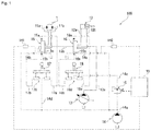
- FIG. 1 illustrates a hydraulic circuit 100 according to a first embodiment.
- the hydraulic circuit 100 includes a first actuator 11, a second actuator 12, a hydraulic pump 13, a pilot pump 14, a first direction switching valve 15, a second direction switching valve 16, a first operation device 17, and a second operation device 18.
- the first actuator 11 is a hydraulic motor that is driven by hydraulic oil supplied from the hydraulic pump 13.
- the second actuator 12 is a hydraulic cylinder that is driven by the hydraulic oil supplied from the hydraulic pump 13.
- the first actuator 11 may be a hydraulic cylinder
- the second actuator 12 may be a hydraulic motor.
- the hydraulic pump 13 is driven by an engine, which is not illustrated, to discharge the hydraulic oil.
- the hydraulic oil discharged from the hydraulic pump 13 is supplied to the first direction switching valve 15 and the second direction switching valve 16 via an oil passage 13a and an oil passage 13b.
- oil passages of the hydraulic oil that is supplied from the hydraulic pump 13 to the first actuator 11 and the second actuator 12 are indicated by solid lines.
- the first direction switching valve 15 is a direction switching valve of a pilot type capable of adjusting a flow rate of the hydraulic oil by switching a direction of the hydraulic oil supplied to the first actuator 11.
- the second direction switching valve 16 is a direction switching valve of the pilot type capable of adjusting the flow rate of the hydraulic oil by switching a direction of the hydraulic oil supplied to the second actuator 12.
- the pilot pump 14 discharges the pilot hydraulic oil as a command input to the first direction switching valve 15 and the second direction switching valve 16.
- oil passages of the pilot hydraulic oil that is supplied from the pilot pump 14 to the first direction switching valve 15 and the second direction switching valve 16 are indicated by broken lines.
- the pilot pump 14 generates a pilot pressure to be applied to the first direction switching valve 15 and the second direction switching valve 16.
- the pilot pump 14 is driven by the engine, which is not illustrated, and discharges the hydraulic oil so as to generate the pilot pressure in an oil passage 14a.
- the oil passage 14a is branched into oil passages 14b, 14c, 14d, 14e.
- the first direction switching valve 15 can be switched to any of plural positions by sliding a spool. In the case where the pilot pressure is applied to none of a pilot port 15a and a pilot port 15b of the first direction switching valve 15, an urging force of a spring keeps the first direction switching valve 15 at a neutral position. In the case where the first direction switching valve 15 is at the neutral position, the hydraulic oil is not supplied from the oil passage 13b to the first actuator 11.
- the first direction switching valve 15 is switched from the neutral position to another position, and the hydraulic oil is supplied to the first actuator 11 via an oil passage 11a or an oil passage 11b.
- the first actuator 11 is rotationally driven in a positive direction or a reverse direction.
- the second direction switching valve 16 can be switched to any of plural positions by sliding a spool. In the case where the pilot pressure is applied to none of a pilot port 16a and a pilot port 16b of the second direction switching valve 16, an urging force of a spring keeps the second direction switching valve 16 at a neutral position. In the case where the second direction switching valve 16 is at the neutral position, the hydraulic oil is not supplied from the oil passage 13a to the second actuator 12.
- the second direction switching valve 16 is switched from the neutral position to another position, and the hydraulic oil is supplied to the second actuator 12 via an oil passage 12a or an oil passage 12b. With the hydraulic oil that is supplied via the oil passage 12a or the oil passage 12b, the second actuator 12 is contracted.
- the first direction switching valve 15 includes a first detection direction switching valve 15c therein.
- the first detection direction switching valve 15c can be switched to any of plural positions by sliding a spool. In the case where the first direction switching valve 15 is kept at a neutral position, the first detection direction switching valve 15c is also kept at a neutral position. In the case where the first direction switching valve 15 is switched from the neutral position to another position, in conjunction therewith, the first detection direction switching valve 15c is also switched from the neutral position to another position.
- the first detection direction switching valve 15c In the case where the first detection direction switching valve 15c is at the neutral position, the first detection direction switching valve 15c does not close the oil passage 14b. Accordingly, the hydraulic oil can flow through the oil passage 14b via the first detection direction switching valve 15c. Meanwhile, in the case where the first detection direction switching valve 15c is at the position other than the neutral position, the first detection direction switching valve 15c closes the oil passage 14b.
- a first pressure switch 141 is connected to the oil passage 14b. It is configured that, when the first operation device 17 is operated to move the first detection direction switching valve 15c from the neutral position to the position other than the neutral position, the oil passage 14b is closed, the pressure is generated in a throttle downstream portion of the oil passage 14b, and this pressure is detected by the first pressure switch 141.
- the first pressure switch 141 detects the operation of the first operation device 17 and outputs this detection signal to an engine control unit (ECU) 10, which will be described below.
- ECU engine control unit
- the second direction switching valve 16 includes a second detection direction switching valve 16c therein.
- the second detection direction switching valve 16c can be switched to any of plural positions by sliding a spool. In the case where the second direction switching valve 16 is kept at a neutral position, the second detection direction switching valve 16c is also kept at a neutral position. In the case where the second direction switching valve 16 is switched from the neutral position to another position, in conjunction therewith, the second detection direction switching valve 16c is also switched from the neutral position to another position.
- the second detection direction switching valve 16c In the case where the second detection direction switching valve 16c is at the neutral position, the second detection direction switching valve 16c does not close the oil passage 14c. Accordingly, the hydraulic oil can flow through the oil passage 14c via the second detection direction switching valve 16c. Meanwhile, in the case where the second detection direction switching valve 16c is at the position other than the neutral position, the second detection direction switching valve 16c closes the oil passage 14c.
- a second pressure switch 142 is connected to the oil passage 14c. It is configured that, when the second operation device 18 is operated to move the second detection direction switching valve 16c from the neutral position to the position other than the neutral position, the oil passage 14c is closed, the pressure is generated in a throttle downstream portion of the oil passage 14c, and this pressure is detected by the second pressure switch 142.
- the second pressure switch 142 detects the operation of the second operation device 18 and outputs this detection signal to the ECU 10, which will be described below.
- the first operation device 17 has a first remote control valve 170 for switching a direction and the pressure of the pilot hydraulic oil to be supplied to the first direction switching valve 15.
- the first remote control valve 170 is connected to the oil passage 14d.
- the first remote control valve 170 is also connected to the pilot port 15a and the pilot port 15b of the first direction switching valve 15 via an oil passage 17a and an oil passage 17b, respectively.
- the first remote control valve 170 supplies, as the pilot hydraulic oil, the hydraulic oil that is supplied from the pilot pump 14 via the oil passage 14d to the first direction switching valve 15.
- the second operation device 18 has a second remote control valve 180 for switching a direction and the pressure of the pilot hydraulic oil to be supplied to the second direction switching valve 16.
- the second remote control valve 180 is connected to the oil passage 14e.
- the second remote control valve 180 is also connected to the pilot port 16a and the pilot port 16b of the second direction switching valve 16 via an oil passage 18a and an oil passage 18b, respectively.
- the second remote control valve 180 supplies, as the pilot hydraulic oil, the hydraulic oil that is supplied from the pilot pump 14 via the oil passage 14e to the second direction switching valve 16.
- An electromagnetic pressure reduction valve 19 (an example of the pressure control unit) is provided in the oil passage 14e between the second remote control valve 180 and the pilot pump 14.
- the electromagnetic pressure reduction valve 19 can control a primary pressure of the pilot hydraulic oil that is discharged from the pilot pump 14 and supplied to the second remote control valve 180.
- the electromagnetic pressure reduction valve 19 can control the pressure according to a magnitude of an input current.
- the hydraulic circuit 100 includes the ECU 10 (an example of the control command transmitter) that transmits a control command to the electromagnetic pressure reduction valve 19.
- the ECU 10 transmits the control command according to the operations of the first operation device 17 and the second operation device 18.
- the ECU 10 determines that the first operation device 17 is operated.
- the ECU 10 determines that the second operation device 18 is operated.
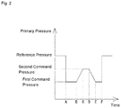
- FIG. 2 is a graph illustrating a situation where the primary pressure of the pilot hydraulic oil that is supplied to the second remote control valve 180 is controlled.
- the ECU 10 When the first operation device 17 starts being operated (at time A in FIG. 2 ), the ECU 10 reduces the primary pressure of the pilot hydraulic oil for the electromagnetic pressure reduction valve 19 from a reference pressure to a first command pressure. Then, while the first operation device 17 is operated (the time A to B in FIG. 2 ), the ECU 10 transmits a first command to the electromagnetic pressure reduction valve 19 so as to keep the primary pressure of the pilot hydraulic oil at the first command pressure.
- the reference pressure is a pressure of the hydraulic oil that is discharged from the pilot pump 14.
- the ECU 10 transmits, to the electromagnetic pressure reduction valve 19, a second command to gradually increase the primary pressure of the pilot hydraulic oil from the first command pressure to a second command pressure.
- the second command pressure is higher than the first command pressure and is lower than the reference pressure. Ratios of the reference pressure, the first command pressure, and the second command pressure are appropriately set.
- a period (the time B to C in FIG. 2 ) in which the primary pressure is gradually increased from the first command pressure to the second command pressure is also appropriately set.
- the ECU 10 transmits, to the electromagnetic pressure reduction valve 19, a command to gradually reduce the primary pressure of the pilot hydraulic oil from the second command pressure to the first command pressure. Thereafter, while only the first operation device 17 is operated (time E to F in FIG. 2 ), the ECU 10 transmits, to the electromagnetic pressure reduction valve 19, a command to keep the primary pressure of the pilot hydraulic oil at the first command pressure.
- the ECU 10 transmits, to the electromagnetic pressure reduction valve 19, a command to increase the primary pressure from the pilot pump 14 to a reference value and keep the primary pressure at the reference value.
- the hydraulic shovel 1 includes a traveling device 2, a work device 3, and a turning device 4.
- the traveling device 2 is driven by receiving power from an engine 42 and drives the hydraulic shovel 1.
- the traveling device 2 includes a left and right pair of crawlers 21, 21 and a left and right pair of travel motors 22L, 22R.
- the traveling device 2 is also provided with a blade 23 and a blade cylinder 24 that is a hydraulic actuator for rotating the blade 23 in a vertical direction.
- the work device 3 is driven by receiving the power from the engine 42 to excavate gravel or the like.
- the work device 3 includes a boom 31, an arm 32, and a bucket 33 and independently drives these components to enable excavation work.
- the boom 31, arm 32, and the bucket 33 each correspond to the working section, and the hydraulic shovel 1 has plural working sections.
- One end of the boom 31 is supported by a front portion of the turning device 4, and the boom 31 is rotated by a boom cylinder 31a that is movable in a freely extendable/contractable manner.
- One end of the arm 32 is supported by the other end of the boom 31, and the arm 32 is rotated by an arm cylinder 32a that is movable in a freely extendable/contractable manner.
- One end of the bucket 33 is supported by the other end of the arm 32, and the bucket 33 is rotated by a bucket cylinder 33a that is movable in a freely extendable/contractable manner.
- the boom cylinder 31a, the arm cylinder 32a, and the bucket cylinder 33a correspond to the hydraulic actuator that drives the working section.
- the turning device 4 turns the work device 3.
- the turning device 4 includes an operation section 41, the engine 42, a turntable 43, a turning motor 44, and the like.
- the turning motor 44 as a hydraulic motor drives the turntable 43 and thereby turns the work device 3.
- plural hydraulic pumps (not illustrated in FIG. 3 ) that are driven by the engine 42 are disposed in the turning device 4. These hydraulic pumps supply the hydraulic oil to the boom cylinder 31a, the arm cylinder 32a, the bucket cylinder 33a, and the like.
- An operator seat 411 is arranged in the operation section 41.
- a left and right pair of work operation levers 412L, 412R is arranged on left and right sides of the operator seat 411, and a pair of travel levers 413L, 413R is arranged in front of the operator seat 411.
- the travel levers 413L, 413R, or the like to control the engine 42, each of the hydraulic motors, each of the hydraulic actuators, or the like, the operator can travel the hydraulic shovel 1, turn the hydraulic shovel 1, perform the work using the hydraulic shovel 1, and the like.
- the hydraulic circuit 5 has: first to third hydraulic actuators 121, 122, 123 (the boom cylinder 31a, the arm cylinder 32a, and the bucket cylinder 33a), the left travel motor 22L, the right travel motor 22R, the turning motor 44, a first hydraulic pump 51, a second hydraulic pump 52, a direction switching valve 53, a pilot pump 54, and a remote control valve 55.
- first to third hydraulic actuators 121, 122, 123 the boom cylinder 31a, the arm cylinder 32a, and the bucket cylinder 33a
- the left travel motor 22L the right travel motor 22R
- the turning motor 44 the turning motor 44
- a first hydraulic pump 51 a second hydraulic pump 52
- a direction switching valve 53 a pilot pump 54
- a remote control valve 55 a circuit related to the blade cylinder 24 and the like is not illustrated for convenience of the description.
- the first hydraulic pump 51 primarily supplies the hydraulic oil to the right travel motor 22R, the third hydraulic actuator 123, and the turning motor 44.
- the second hydraulic pump 52 primarily supplies the hydraulic oil to the first hydraulic actuator 121, the second hydraulic actuator 122, and the left travel motor 22L.
- the direction switching valve 53 is provided in a manner to correspond to each of the hydraulic actuators and is configured to be able to switch the direction and the flow rate of the hydraulic oil that is supplied from the first hydraulic pump 51 or the second hydraulic pump 52 to each of the hydraulic actuators.
- the plural direction switching valves 53 will collectively be referred to as control valves.
- a structure of each of the direction switching valves 53 is the same as the first direction switching valve 15 or the second direction switching valve 16 in the first embodiment, and thus a detailed description thereon will not be made.
- Each of the direction switching valves 53 includes a detection direction switching valve therein.
- the detection direction switching valve provided in each of the direction switching valve 53c for the left travel motor and the direction switching valve 53d for the right travel motor closes or opens an oil passage 54a from the pilot pump 54.
- the detection direction switching valve provided in each of the direction switching valve 53a for the first hydraulic actuator, the direction switching valve 53b for the second hydraulic actuator, the direction switching valve 53e for the third hydraulic actuator, and the turning direction switching valve 53f closes or opens an oil passage 54b from the pilot pump 54.
- a structure of each of the detection direction switching valves is the same as that of the first detection direction switching valve 15c or the second detection direction switching valve 16c in the first embodiment, and thus a detailed description thereon will not be made.
- the first pressure switch 141 is connected to the oil passage 54a.
- the travel levers 413L, 413R are operated to move the detection direction switching valve of the direction switching valve 53c for the left travel motor or the direction switching valve 53d for the right travel motor from a neutral position to a position other than the neutral position, the oil passage 54a is closed, the pressure is generated in a throttle downstream portion of the oil passage 54a, and this pressure is detected by the first pressure switch 141.
- the first pressure switch 141 detects the operations of the travel levers 413L, 413R and outputs this detection signal to the ECU 10.
- the second pressure switch 142 is connected to the oil passage 54b.
- the work operation lever 412R is operated to move the detection direction switching valve of the direction switching valve 53a for the first hydraulic actuator from a neutral position to a position other than the neutral position, the oil passage 54b is closed, the pressure is generated in a throttle downstream portion of the oil passage 54b, and this pressure is detected by the second pressure switch 142.
- the second pressure switch 142 detects the operation of the work operation lever 412R and outputs this detection signal to the ECU 10.
- the pilot pump 54 discharges the pilot hydraulic oil as a command input to the direction switching valves 53 (53a, 53b, 53c, 53d, 53e, 53f).
- the oil passage between the pilot pump 54 and the direction switching valve 53 is not partially illustrated.
- the remote control valve 55 is configured to be able to switch and adjust the direction of the pilot hydraulic oil that flows into the direction switching valves 53 according to the operations of the work operation levers 412L, 412R and the travel levers 413L, 413R.
- the remote control valve 55 is provided for each of the hydraulic actuators and each of the corresponding direction switching valves 53.
- a remote control valve 55a for the first hydraulic actuator that corresponds to the work operation lever 412R for contracting the first hydraulic actuator 121 is provided, and the remote control valve 55a for the first hydraulic actuator switches the direction of the pilot hydraulic oil as the command that is supplied to the direction switching valve 53a for the first hydraulic actuator.
- a remote control valve 55b for the left travel motor that corresponds to the travel lever 413L for rotating the left travel motor 22L is provided, and the remote control valve 55b for the left travel motor switches the direction of the pilot hydraulic oil as the command that is supplied to the direction switching valve 53c for the left travel motor.
- a remote control valve 55c for the right travel motor that corresponds to the travel lever 413R for rotating the right travel motor 22R is provided, and the remote control valve 55c for the right travel motor switches the direction of the pilot hydraulic oil as the command that is supplied to the direction switching valve 53d for the right travel motor.
- the remote control valves 55 corresponding to the other direction switching valves 53d, 53e, 53f are provided.
- the electromagnetic pressure reduction valve 19 is provided in an oil passage between the remote control valve 55a for the first hydraulic actuator and the pilot pump 54.
- the electromagnetic pressure reduction valve 19 can control the primary pressure of the pilot hydraulic oil that is discharged from the pilot pump 14 and is supplied to the remote control valve 55a for the first hydraulic actuator.
- the hydraulic circuit 5 includes the ECU 10 that transmits the control command to the electromagnetic pressure reduction valve 19.
- the ECU 10 transmits the control command according to the operation of each of the work operation levers 412L, 412R and the travel levers 413L, 413R.
- the hydraulic circuit 5 includes a merging switching valve 56.
- the merging switching valve 56 is a direction switching valve of the pilot type capable of merging the hydraulic oil discharged from the first hydraulic pump 51 and the second hydraulic pump 52.
- the merging switching valve 56 can be switched to a position 56X or the position 56Y by sliding a spool. In the case where the pilot pressure is applied to a pilot port 56a and a pilot port 56b of the merging switching valve 56, the merging switching valve 56 is switched to the position 56Y. In the case where the pilot pressure is not applied to the pilot port 56a or the pilot port 56b of the merging switching valve 56, an urging force of a spring keeps the merging switching valve 56 at the position 56X.
- the merging switching valve 56 is at the position 56X, the hydraulic oil discharged from the first hydraulic pump 51 and the hydraulic oil discharged from the second hydraulic pump 52 flow separately without being merged, the hydraulic oil discharged from the first hydraulic pump 51 is supplied to the direction switching valve 53d for the right travel motor, the direction switching valve 53e for the third hydraulic actuator, and the turning direction switching valve 53f, and the hydraulic oil discharged from the second hydraulic pump 52 is supplied to the direction switching valve 53a for the first hydraulic actuator, the direction switching valve 53b for the second hydraulic actuator, and the direction switching valve 53c for the left travel motor.
- the ECU 10 When the travel levers 413L, 413R are operated, the ECU 10 reduces the primary pressure of the pilot hydraulic oil for the electromagnetic pressure reduction valve 19 from the reference pressure to the first command pressure. While the travel levers 413L, 413R are operated, the ECU 10 transmits, to the electromagnetic pressure reduction valve 19, the first command to keep the primary pressure of the pilot hydraulic oil at the first command pressure.
- the ECU 10 transmits, to the electromagnetic pressure reduction valve 19, the second command to gradually increase the primary pressure of the pilot pressure oil from the first command pressure to the second command pressure. Thereafter, while the travel levers 413L, 413R and the work operation lever 412R are operated, a command is transmitted to the electromagnetic pressure reduction valve 19 to keep the primary pressure of the pilot hydraulic oil at the second command pressure. In this way, when the first hydraulic actuator 121 is driven during travel, the pilot pressure that is applied to the direction switching valve 53a for the first hydraulic actuator is gradually increased from the first command pressure to the second command pressure.
- the hydraulic oil from the first hydraulic pump 51 and the second hydraulic pump 52 is not rapidly supplied to the first hydraulic actuator 121, and thus it is possible to prevent a rapid reduction in a travel speed caused by the rapid reduction in the oil amount of the hydraulic oil supplied to the travel motors 22L, 22R.
- the hydraulic oil discharged from the first hydraulic pump 51 and the hydraulic oil discharged from the second hydraulic pump 52 are merged by the merging switching valve 56 during the travel. Thus, it is possible to effectively prevent the rapid reduction in the oil amount of the hydraulic oil supplied to the travel motors 22L, 22R.
- the ECU 10 transmits, to the electromagnetic pressure reduction valve 19, the command to gradually reduce the primary pressure of the pilot hydraulic oil from the second command pressure to the first command pressure. Thereafter, while only the travel levers 413L, 413R are operated, the ECU 10 transmits, to the electromagnetic pressure reduction valve 19, the command to keep the primary pressure of the pilot hydraulic oil at the first command pressure.
- the ECU 10 transmits, to the electromagnetic pressure reduction valve 19, a command to increase the primary pressure from the pilot pump 54 to a reference value from a first command value and keep the primary pressure at the reference value.
Landscapes
- Engineering & Computer Science (AREA)
- General Engineering & Computer Science (AREA)
- Mining & Mineral Resources (AREA)
- Civil Engineering (AREA)
- Structural Engineering (AREA)
- Physics & Mathematics (AREA)
- Fluid Mechanics (AREA)
- Mechanical Engineering (AREA)
- Fluid-Pressure Circuits (AREA)
- Operation Control Of Excavators (AREA)
Abstract
Description
- The present invention relates to a hydraulic circuit for a work vehicle.
- In Patent Literature 1 below, in a construction machine that includes a hydraulic control circuit for driving a plurality of hydraulic actuators including a travel actuator, as a technique of preventing a rapid reduction in a travel speed due to a reduction in a flow rate of hydraulic oil that is supplied from a hydraulic pump to the travel actuator at the time of transition from single operation of the travel actuator to combined operation of the travel actuator and another actuator, the following technique is disclosed that return oil of pilot hydraulic oil acting on a pilot pressure receiving section on a return side of a direction switching valve is throttled by a flow rate control valve when the combined operation of the travel actuator and another actuator is performed in the state where the travel actuator is operated and that a rapid reduction in the flow rate of the hydraulic oil supplied to the travel actuator is prevented by slowing an opening speed of a spool and gradually increasing the hydraulic oil amount of the other actuator when a pilot pressure acts on a pilot pressure receiving section on an inlet side of the direction switching valve.
- In
Patent Literature 2 below, as a technique for preventing adverse effects such as degraded operability while securing a cushioning function during a sudden operation, in a hydraulic circuit of a construction machine that includes: a pressure reducing valve that supplies, as the pilot pressure, a secondary pressure corresponding to an operation amount to a pilot line to a pilot port of a control valve; and a pilot hydraulic pressure source as a primary pressure source of this pressure reducing valve, a technique of providing, on a primary side of the pressure reducing valve, a first throttle and a bleed-offline that communicates the pilot line with a tank and installing a second throttle in the bleed-offline is disclosed. -
- Patent Literature 1: Japanese Unexamined Patent Application Publication No.
2005-121155 - Patent Literature 2: Japanese Unexamined Patent Application Publication No.
2006-125627 - In Patent Literature 1, in order to throttle the return oil, the flow rate control valve is installed in a return oil passage for the pilot hydraulic oil that acts on the pilot pressure receiving section on the return side of the direction switching valve. Thus, there is a problem that the flow rate control valve has to be installed per remote control valve that controls the actuator, the flow rate of which is desired to be controlled, during the combined operation, which increases cost. In
Patent Literature 2, the first throttle is arranged on the primary side of the pressure reducing valve to suppress a significant increase in an absolute value of the pilot pressure. Thus, there is no need for arranging means for throttling the pilot hydraulic oil per the pressure receiving section of the direction switching valve. However, since the bleed-offline that includes the second throttle for slowing a rise of the pilot pressure is arranged on the secondary side of the pressure reducing valve, there is a problem that the bleed-offline has to be arranged per pressure receiving section of the direction switching valve, which increases cost. - In view of the above problems, the present invention has a purpose of providing a hydraulic circuit in an inexpensive configuration for a work vehicle, the hydraulic circuit capable of preventing a shock caused by a rapid reduction in an oil amount that occurs at the time of transition from single operation for driving a single hydraulic actuator to combined operation for driving a plurality of hydraulic actuators in the work vehicle that includes the plurality of hydraulic actuators.
- A hydraulic circuit for a work vehicle according to the present invention includes: a first actuator; a second actuator; a hydraulic pump that supplies hydraulic oil to the first actuator and the second actuator; a first direction switching valve that switches a direction of and adjusts a flow rate of the hydraulic oil supplied to the first actuator; a second direction switching valve that switches a direction of and adjusts a flow rate of the hydraulic oil supplied to the second actuator; a pilot pump that supplies pilot hydraulic oil to the first direction switching valve and the second direction switching valve; a first operation device capable of switching, according to an operation, a direction and a pressure of the pilot hydraulic oil supplied to the first direction switching valve; a second operation device capable of switching, according to an operation, a direction and a pressure of the pilot hydraulic oil supplied to the second direction switching valve; a pressure control unit that is provided in an oil passage between the second operation device and the pilot pump and controls a primary pressure of the pilot hydraulic oil supplied to the second operation device; and a control command transmitter that transmits a control command to the pressure control unit.
- While the first operation device is operated, the control command transmitter transmits, to the pressure control unit, a first command to reduce the primary pressure from a reference pressure to a first command pressure and keep the primary pressure at the first command pressure.
- When the second operation device is operated in a state where the first operation device is operated, the control command transmitter transmits, to the pressure control unit, a second command to gradually increase the primary pressure from the first command pressure to the second command pressure.
- In the present invention, control command transmitter may transmit, to the pressure control unit, a command to gradually reduce the primary pressure from the second command pressure to the first command pressure when the second operation device in the state where the first operation device is operated.
- In the present invention, the first actuator may be a first travel hydraulic motor, and the second actuator may be a work hydraulic actuator.
- The present invention may further include: a first circuit system that includes the first travel hydraulic motor and a first hydraulic pump for supplying the hydraulic oil to the first travel hydraulic motor; a second circuit system that includes the work hydraulic actuator, a second travel hydraulic motor, and a second hydraulic pump for supplying the hydraulic oil to the work hydraulic actuator and the second travel hydraulic motor; and a merging switching valve that merges the hydraulic oil of the first circuit system and the hydraulic oil of the second circuit system.
- According to the present invention, at the time of transition from single operation for driving the first actuator only to combined operation for simultaneously driving the first actuator and the second actuator, the pressure of the pilot hydraulic oil that is supplied to the second operation device corresponding to the second actuator is gradually increased from the first command pressure to the second command pressure. Thus, it is possible to prevent a shock caused by a rapid reduction in an oil amount of the hydraulic oil supplied to the first actuator. In addition, only by installing a branch passage leading to the plural operation devices on a downstream side of the pressure control unit, the control of the present invention can be adopted for the plural actuators. Therefore, it is possible to provide the hydraulic circuit with the inexpensive configuration.
-
-
FIG. 1 is a view illustrating a hydraulic circuit in a work vehicle according to a first embodiment. -
FIG. 2 is a graph illustrating a situation where a primary pressure of pilot hydraulic oil that is supplied to a second remote control valve is controlled. -
FIG. 3 is a side view illustrating a work vehicle according to a second embodiment. -
FIG. 4 is a view illustrating a hydraulic circuit in the work vehicle according to the second embodiment. - A description will hereinafter be made on embodiments of the present invention with reference to the drawings.
-
FIG. 1 illustrates ahydraulic circuit 100 according to a first embodiment. Thehydraulic circuit 100 includes afirst actuator 11, asecond actuator 12, ahydraulic pump 13, apilot pump 14, a firstdirection switching valve 15, a seconddirection switching valve 16, afirst operation device 17, and asecond operation device 18. - The
first actuator 11 is a hydraulic motor that is driven by hydraulic oil supplied from thehydraulic pump 13. Thesecond actuator 12 is a hydraulic cylinder that is driven by the hydraulic oil supplied from thehydraulic pump 13. However, thefirst actuator 11 may be a hydraulic cylinder, and thesecond actuator 12 may be a hydraulic motor. - The
hydraulic pump 13 is driven by an engine, which is not illustrated, to discharge the hydraulic oil. The hydraulic oil discharged from thehydraulic pump 13 is supplied to the firstdirection switching valve 15 and the seconddirection switching valve 16 via anoil passage 13a and anoil passage 13b. InFIG. 1 , oil passages of the hydraulic oil that is supplied from thehydraulic pump 13 to thefirst actuator 11 and thesecond actuator 12 are indicated by solid lines. - The first
direction switching valve 15 is a direction switching valve of a pilot type capable of adjusting a flow rate of the hydraulic oil by switching a direction of the hydraulic oil supplied to thefirst actuator 11. The seconddirection switching valve 16 is a direction switching valve of the pilot type capable of adjusting the flow rate of the hydraulic oil by switching a direction of the hydraulic oil supplied to thesecond actuator 12. - The
pilot pump 14 discharges the pilot hydraulic oil as a command input to the firstdirection switching valve 15 and the seconddirection switching valve 16. InFIG. 1 , oil passages of the pilot hydraulic oil that is supplied from thepilot pump 14 to the firstdirection switching valve 15 and the seconddirection switching valve 16 are indicated by broken lines. Thepilot pump 14 generates a pilot pressure to be applied to the firstdirection switching valve 15 and the seconddirection switching valve 16. Thepilot pump 14 is driven by the engine, which is not illustrated, and discharges the hydraulic oil so as to generate the pilot pressure in anoil passage 14a. Theoil passage 14a is branched intooil passages - The first
direction switching valve 15 can be switched to any of plural positions by sliding a spool. In the case where the pilot pressure is applied to none of apilot port 15a and apilot port 15b of the firstdirection switching valve 15, an urging force of a spring keeps the firstdirection switching valve 15 at a neutral position. In the case where the firstdirection switching valve 15 is at the neutral position, the hydraulic oil is not supplied from theoil passage 13b to thefirst actuator 11. - Meanwhile, in the case where the pilot pressure is applied to the
pilot port 15a or thepilot port 15b of the firstdirection switching valve 15, the firstdirection switching valve 15 is switched from the neutral position to another position, and the hydraulic oil is supplied to thefirst actuator 11 via anoil passage 11a or an oil passage 11b. With the hydraulic oil that is supplied via theoil passage 11a or the oil passage 11b, thefirst actuator 11 is rotationally driven in a positive direction or a reverse direction. - The second
direction switching valve 16 can be switched to any of plural positions by sliding a spool. In the case where the pilot pressure is applied to none of apilot port 16a and apilot port 16b of the seconddirection switching valve 16, an urging force of a spring keeps the seconddirection switching valve 16 at a neutral position. In the case where the seconddirection switching valve 16 is at the neutral position, the hydraulic oil is not supplied from theoil passage 13a to thesecond actuator 12. - Meanwhile, in the case where the pilot pressure is applied to the
pilot port 16a or thepilot port 16b of the seconddirection switching valve 16, the seconddirection switching valve 16 is switched from the neutral position to another position, and the hydraulic oil is supplied to thesecond actuator 12 via anoil passage 12a or anoil passage 12b. With the hydraulic oil that is supplied via theoil passage 12a or theoil passage 12b, thesecond actuator 12 is contracted. - The first
direction switching valve 15 includes a first detectiondirection switching valve 15c therein. The first detectiondirection switching valve 15c can be switched to any of plural positions by sliding a spool. In the case where the firstdirection switching valve 15 is kept at a neutral position, the first detectiondirection switching valve 15c is also kept at a neutral position. In the case where the firstdirection switching valve 15 is switched from the neutral position to another position, in conjunction therewith, the first detectiondirection switching valve 15c is also switched from the neutral position to another position. - In the case where the first detection
direction switching valve 15c is at the neutral position, the first detectiondirection switching valve 15c does not close theoil passage 14b. Accordingly, the hydraulic oil can flow through theoil passage 14b via the first detectiondirection switching valve 15c. Meanwhile, in the case where the first detectiondirection switching valve 15c is at the position other than the neutral position, the first detectiondirection switching valve 15c closes theoil passage 14b. - A
first pressure switch 141 is connected to theoil passage 14b. It is configured that, when thefirst operation device 17 is operated to move the first detectiondirection switching valve 15c from the neutral position to the position other than the neutral position, theoil passage 14b is closed, the pressure is generated in a throttle downstream portion of theoil passage 14b, and this pressure is detected by thefirst pressure switch 141. Thefirst pressure switch 141 detects the operation of thefirst operation device 17 and outputs this detection signal to an engine control unit (ECU) 10, which will be described below. - The second
direction switching valve 16 includes a second detectiondirection switching valve 16c therein. The second detectiondirection switching valve 16c can be switched to any of plural positions by sliding a spool. In the case where the seconddirection switching valve 16 is kept at a neutral position, the second detectiondirection switching valve 16c is also kept at a neutral position. In the case where the seconddirection switching valve 16 is switched from the neutral position to another position, in conjunction therewith, the second detectiondirection switching valve 16c is also switched from the neutral position to another position. - In the case where the second detection
direction switching valve 16c is at the neutral position, the second detectiondirection switching valve 16c does not close theoil passage 14c. Accordingly, the hydraulic oil can flow through theoil passage 14c via the second detectiondirection switching valve 16c. Meanwhile, in the case where the second detectiondirection switching valve 16c is at the position other than the neutral position, the second detectiondirection switching valve 16c closes theoil passage 14c. - A
second pressure switch 142 is connected to theoil passage 14c. It is configured that, when thesecond operation device 18 is operated to move the second detectiondirection switching valve 16c from the neutral position to the position other than the neutral position, theoil passage 14c is closed, the pressure is generated in a throttle downstream portion of theoil passage 14c, and this pressure is detected by thesecond pressure switch 142. Thesecond pressure switch 142 detects the operation of thesecond operation device 18 and outputs this detection signal to theECU 10, which will be described below. - The
first operation device 17 has a firstremote control valve 170 for switching a direction and the pressure of the pilot hydraulic oil to be supplied to the firstdirection switching valve 15. The firstremote control valve 170 is connected to theoil passage 14d. The firstremote control valve 170 is also connected to thepilot port 15a and thepilot port 15b of the firstdirection switching valve 15 via anoil passage 17a and anoil passage 17b, respectively. The firstremote control valve 170 supplies, as the pilot hydraulic oil, the hydraulic oil that is supplied from thepilot pump 14 via theoil passage 14d to the firstdirection switching valve 15. By operating thefirst operation device 17, the position of the firstdirection switching valve 15 is switched, the direction of the hydraulic oil to be supplied to thefirst actuator 11 is switched, and the flow rate of the hydraulic oil can thereby be adjusted. - The
second operation device 18 has a secondremote control valve 180 for switching a direction and the pressure of the pilot hydraulic oil to be supplied to the seconddirection switching valve 16. The secondremote control valve 180 is connected to the oil passage 14e. The secondremote control valve 180 is also connected to thepilot port 16a and thepilot port 16b of the seconddirection switching valve 16 via anoil passage 18a and anoil passage 18b, respectively. The secondremote control valve 180 supplies, as the pilot hydraulic oil, the hydraulic oil that is supplied from thepilot pump 14 via the oil passage 14e to the seconddirection switching valve 16. By operating thesecond operation device 18, the position of the seconddirection switching valve 16 is switched, the direction of the hydraulic oil to be supplied to thesecond actuator 12 is switched, and the flow rate of the hydraulic oil can thereby be adjusted. - An electromagnetic pressure reduction valve 19 (an example of the pressure control unit) is provided in the oil passage 14e between the second
remote control valve 180 and thepilot pump 14. The electromagneticpressure reduction valve 19 can control a primary pressure of the pilot hydraulic oil that is discharged from thepilot pump 14 and supplied to the secondremote control valve 180. The electromagneticpressure reduction valve 19 can control the pressure according to a magnitude of an input current. - The
hydraulic circuit 100 includes the ECU 10 (an example of the control command transmitter) that transmits a control command to the electromagneticpressure reduction valve 19. TheECU 10 transmits the control command according to the operations of thefirst operation device 17 and thesecond operation device 18. When receiving the detection signal from thefirst pressure switch 141, theECU 10 determines that thefirst operation device 17 is operated. When receiving the detection signal from thesecond pressure switch 142, theECU 10 determines that thesecond operation device 18 is operated. - Next, a description will be made on control of the electromagnetic
pressure reduction valve 19 by theECU 10 with reference toFIG. 2. FIG. 2 is a graph illustrating a situation where the primary pressure of the pilot hydraulic oil that is supplied to the secondremote control valve 180 is controlled. - When the
first operation device 17 starts being operated (at time A inFIG. 2 ), theECU 10 reduces the primary pressure of the pilot hydraulic oil for the electromagneticpressure reduction valve 19 from a reference pressure to a first command pressure. Then, while thefirst operation device 17 is operated (the time A to B inFIG. 2 ), theECU 10 transmits a first command to the electromagneticpressure reduction valve 19 so as to keep the primary pressure of the pilot hydraulic oil at the first command pressure. The reference pressure is a pressure of the hydraulic oil that is discharged from thepilot pump 14. - Next, when the
second operation device 18 is operated in a state where thefirst operation device 17 is operated (the time B inFIG. 2 ), theECU 10 transmits, to the electromagneticpressure reduction valve 19, a second command to gradually increase the primary pressure of the pilot hydraulic oil from the first command pressure to a second command pressure. The second command pressure is higher than the first command pressure and is lower than the reference pressure. Ratios of the reference pressure, the first command pressure, and the second command pressure are appropriately set. A period (the time B to C inFIG. 2 ) in which the primary pressure is gradually increased from the first command pressure to the second command pressure is also appropriately set. - Thereafter, while the
first operation device 17 and thesecond operation device 18 are operated (the time C to D inFIG. 2 ), a command is transmitted to the electromagneticpressure reduction valve 19 to keep the primary pressure of the pilot hydraulic oil at the second command pressure. In this way, at the time of transition from single operation for driving thefirst actuator 11 only to combined operation for simultaneously driving thefirst actuator 11 and thesecond actuator 12, the pilot pressure to be supplied to the seconddirection switching valve 16 via the secondremote control valve 180 is gradually increased from the first command pressure to the second command pressure via the secondremote control valve 180. As a result, the hydraulic oil from thehydraulic pump 13 is not rapidly supplied to thesecond actuator 12, and thus a shock caused by a rapid reduction in an oil amount of the hydraulic oil that is supplied to thefirst actuator 11 can be prevented. - Next, when the
second operation device 18 is no longer operated in the state where thefirst operation device 17 is operated (the time D inFIG. 2 ), theECU 10 transmits, to the electromagneticpressure reduction valve 19, a command to gradually reduce the primary pressure of the pilot hydraulic oil from the second command pressure to the first command pressure. Thereafter, while only thefirst operation device 17 is operated (time E to F inFIG. 2 ), theECU 10 transmits, to the electromagneticpressure reduction valve 19, a command to keep the primary pressure of the pilot hydraulic oil at the first command pressure. - Furthermore, when the
first operation device 17 is no longer operated (the time F inFIG. 2 ), theECU 10 transmits, to the electromagneticpressure reduction valve 19, a command to increase the primary pressure from thepilot pump 14 to a reference value and keep the primary pressure at the reference value. - First, a description will be made on a schematic structure of a hydraulic shovel 1 as an example of a work vehicle with reference to
FIG. 3 . However, the work vehicle is not limited to the hydraulic shovel 1 and may be another vehicle such as a wheel loader. The hydraulic shovel 1 includes a travelingdevice 2, a work device 3, and a turning device 4. - The traveling
device 2 is driven by receiving power from anengine 42 and drives the hydraulic shovel 1. The travelingdevice 2 includes a left and right pair ofcrawlers travel motors right travel motors right crawlers device 2 is also provided with ablade 23 and ablade cylinder 24 that is a hydraulic actuator for rotating theblade 23 in a vertical direction. - The work device 3 is driven by receiving the power from the
engine 42 to excavate gravel or the like. The work device 3 includes aboom 31, anarm 32, and abucket 33 and independently drives these components to enable excavation work. Theboom 31,arm 32, and thebucket 33 each correspond to the working section, and the hydraulic shovel 1 has plural working sections. - One end of the
boom 31 is supported by a front portion of the turning device 4, and theboom 31 is rotated by aboom cylinder 31a that is movable in a freely extendable/contractable manner. One end of thearm 32 is supported by the other end of theboom 31, and thearm 32 is rotated by anarm cylinder 32a that is movable in a freely extendable/contractable manner. One end of thebucket 33 is supported by the other end of thearm 32, and thebucket 33 is rotated by abucket cylinder 33a that is movable in a freely extendable/contractable manner. Theboom cylinder 31a, thearm cylinder 32a, and thebucket cylinder 33a correspond to the hydraulic actuator that drives the working section. - The turning device 4 turns the work device 3. The turning device 4 includes an
operation section 41, theengine 42, aturntable 43, a turningmotor 44, and the like. The turningmotor 44 as a hydraulic motor drives theturntable 43 and thereby turns the work device 3. In addition, plural hydraulic pumps (not illustrated inFIG. 3 ) that are driven by theengine 42 are disposed in the turning device 4. These hydraulic pumps supply the hydraulic oil to theboom cylinder 31a, thearm cylinder 32a, thebucket cylinder 33a, and the like. - An
operator seat 411 is arranged in theoperation section 41. A left and right pair of work operation levers 412L, 412R is arranged on left and right sides of theoperator seat 411, and a pair oftravel levers operator seat 411. When an operator is seated on theoperator seat 411 and operates the work operation levers 412L, 412R, the travel levers 413L, 413R, or the like to control theengine 42, each of the hydraulic motors, each of the hydraulic actuators, or the like, the operator can travel the hydraulic shovel 1, turn the hydraulic shovel 1, perform the work using the hydraulic shovel 1, and the like. - A description will be made on a hydraulic circuit 5 provided in the hydraulic shovel 1 with reference to
FIG. 4 . The hydraulic circuit 5 has: first to thirdhydraulic actuators boom cylinder 31a, thearm cylinder 32a, and thebucket cylinder 33a), theleft travel motor 22L, theright travel motor 22R, the turningmotor 44, a firsthydraulic pump 51, a secondhydraulic pump 52, adirection switching valve 53, apilot pump 54, and aremote control valve 55. InFIG. 4 , a circuit related to theblade cylinder 24 and the like is not illustrated for convenience of the description. - In a second embodiment, the first
hydraulic pump 51 primarily supplies the hydraulic oil to theright travel motor 22R, the thirdhydraulic actuator 123, and the turningmotor 44. The secondhydraulic pump 52 primarily supplies the hydraulic oil to the firsthydraulic actuator 121, the secondhydraulic actuator 122, and theleft travel motor 22L. - The
direction switching valve 53 is provided in a manner to correspond to each of the hydraulic actuators and is configured to be able to switch the direction and the flow rate of the hydraulic oil that is supplied from the firsthydraulic pump 51 or the secondhydraulic pump 52 to each of the hydraulic actuators. The pluraldirection switching valves 53 will collectively be referred to as control valves. More specifically, in the second embodiment, adirection switching valve 53a for a first hydraulic actuator corresponding to the firsthydraulic actuator 121, adirection switching valve 53b for a second hydraulic actuator corresponding to the secondhydraulic actuator 122, adirection switching valve 53c for a left travel motor corresponding to theleft travel motor 22L, adirection switching valve 53d for a right travel motor corresponding to theright travel motor 22R, adirection switching valve 53e for a third hydraulic actuator corresponding to the thirdhydraulic actuator 123, and a turning direction switching valve 53f corresponding to the turningmotor 44 are provided. A structure of each of thedirection switching valves 53 is the same as the firstdirection switching valve 15 or the seconddirection switching valve 16 in the first embodiment, and thus a detailed description thereon will not be made. - Each of the
direction switching valves 53 includes a detection direction switching valve therein. The detection direction switching valve provided in each of thedirection switching valve 53c for the left travel motor and thedirection switching valve 53d for the right travel motor closes or opens anoil passage 54a from thepilot pump 54. Meanwhile, the detection direction switching valve provided in each of thedirection switching valve 53a for the first hydraulic actuator, thedirection switching valve 53b for the second hydraulic actuator, thedirection switching valve 53e for the third hydraulic actuator, and the turning direction switching valve 53f closes or opens anoil passage 54b from thepilot pump 54. A structure of each of the detection direction switching valves is the same as that of the first detectiondirection switching valve 15c or the second detectiondirection switching valve 16c in the first embodiment, and thus a detailed description thereon will not be made. - The
first pressure switch 141 is connected to theoil passage 54a. When the travel levers 413L, 413R are operated to move the detection direction switching valve of thedirection switching valve 53c for the left travel motor or thedirection switching valve 53d for the right travel motor from a neutral position to a position other than the neutral position, theoil passage 54a is closed, the pressure is generated in a throttle downstream portion of theoil passage 54a, and this pressure is detected by thefirst pressure switch 141. Thefirst pressure switch 141 detects the operations of the travel levers 413L, 413R and outputs this detection signal to theECU 10. - The
second pressure switch 142 is connected to theoil passage 54b. When thework operation lever 412R is operated to move the detection direction switching valve of thedirection switching valve 53a for the first hydraulic actuator from a neutral position to a position other than the neutral position, theoil passage 54b is closed, the pressure is generated in a throttle downstream portion of theoil passage 54b, and this pressure is detected by thesecond pressure switch 142. Thesecond pressure switch 142 detects the operation of thework operation lever 412R and outputs this detection signal to theECU 10. - The
pilot pump 54 discharges the pilot hydraulic oil as a command input to the direction switching valves 53 (53a, 53b, 53c, 53d, 53e, 53f). InFIG. 4 , the oil passage between thepilot pump 54 and thedirection switching valve 53 is not partially illustrated. - The
remote control valve 55 is configured to be able to switch and adjust the direction of the pilot hydraulic oil that flows into thedirection switching valves 53 according to the operations of the work operation levers 412L, 412R and the travel levers 413L, 413R. Theremote control valve 55 is provided for each of the hydraulic actuators and each of the correspondingdirection switching valves 53. For example, as illustrated inFIG. 4 , aremote control valve 55a for the first hydraulic actuator that corresponds to thework operation lever 412R for contracting the firsthydraulic actuator 121 is provided, and theremote control valve 55a for the first hydraulic actuator switches the direction of the pilot hydraulic oil as the command that is supplied to thedirection switching valve 53a for the first hydraulic actuator. Meanwhile, aremote control valve 55b for the left travel motor that corresponds to thetravel lever 413L for rotating theleft travel motor 22L is provided, and theremote control valve 55b for the left travel motor switches the direction of the pilot hydraulic oil as the command that is supplied to thedirection switching valve 53c for the left travel motor. Similarly, aremote control valve 55c for the right travel motor that corresponds to thetravel lever 413R for rotating theright travel motor 22R is provided, and theremote control valve 55c for the right travel motor switches the direction of the pilot hydraulic oil as the command that is supplied to thedirection switching valve 53d for the right travel motor. Although not illustrated inFIG. 4 , theremote control valves 55 corresponding to the otherdirection switching valves - The electromagnetic
pressure reduction valve 19 is provided in an oil passage between theremote control valve 55a for the first hydraulic actuator and thepilot pump 54. The electromagneticpressure reduction valve 19 can control the primary pressure of the pilot hydraulic oil that is discharged from thepilot pump 14 and is supplied to theremote control valve 55a for the first hydraulic actuator. - The hydraulic circuit 5 includes the
ECU 10 that transmits the control command to the electromagneticpressure reduction valve 19. TheECU 10 transmits the control command according to the operation of each of the work operation levers 412L, 412R and the travel levers 413L, 413R. - The hydraulic circuit 5 includes a
merging switching valve 56. The mergingswitching valve 56 is a direction switching valve of the pilot type capable of merging the hydraulic oil discharged from the firsthydraulic pump 51 and the secondhydraulic pump 52. The mergingswitching valve 56 can be switched to aposition 56X or theposition 56Y by sliding a spool. In the case where the pilot pressure is applied to apilot port 56a and apilot port 56b of themerging switching valve 56, themerging switching valve 56 is switched to theposition 56Y. In the case where the pilot pressure is not applied to thepilot port 56a or thepilot port 56b of themerging switching valve 56, an urging force of a spring keeps themerging switching valve 56 at theposition 56X. An oil passage from theremote control valve 55c for the right travel motor is connected to thepilot port 56a, and an oil passage from theremote control valve 55b for the left travel motor is connected to thepilot port 56b. As a result, when the left and right travel levers 413L, 413R are simultaneously operated, that is, a travel operation is performed, themerging switching valve 56 is switched to theposition 56Y. - In the case where the
merging switching valve 56 is at theposition 56X, the hydraulic oil discharged from the firsthydraulic pump 51 and the hydraulic oil discharged from the secondhydraulic pump 52 flow separately without being merged, the hydraulic oil discharged from the firsthydraulic pump 51 is supplied to thedirection switching valve 53d for the right travel motor, thedirection switching valve 53e for the third hydraulic actuator, and the turning direction switching valve 53f, and the hydraulic oil discharged from the secondhydraulic pump 52 is supplied to thedirection switching valve 53a for the first hydraulic actuator, thedirection switching valve 53b for the second hydraulic actuator, and thedirection switching valve 53c for the left travel motor. - In the case where the
merging switching valve 56 is at theposition 56Y, the hydraulic oil discharged from the firsthydraulic pump 51 and the hydraulic oil discharged from the secondhydraulic pump 52 are merged. - When the travel levers 413L, 413R are operated, the
ECU 10 reduces the primary pressure of the pilot hydraulic oil for the electromagneticpressure reduction valve 19 from the reference pressure to the first command pressure. While the travel levers 413L, 413R are operated, theECU 10 transmits, to the electromagneticpressure reduction valve 19, the first command to keep the primary pressure of the pilot hydraulic oil at the first command pressure. - Next, when the
work operation lever 412R is operated in the state where the travel levers 413L, 413R are operated, theECU 10 transmits, to the electromagneticpressure reduction valve 19, the second command to gradually increase the primary pressure of the pilot pressure oil from the first command pressure to the second command pressure. Thereafter, while the travel levers 413L, 413R and thework operation lever 412R are operated, a command is transmitted to the electromagneticpressure reduction valve 19 to keep the primary pressure of the pilot hydraulic oil at the second command pressure. In this way, when the firsthydraulic actuator 121 is driven during travel, the pilot pressure that is applied to thedirection switching valve 53a for the first hydraulic actuator is gradually increased from the first command pressure to the second command pressure. As a result, the hydraulic oil from the firsthydraulic pump 51 and the secondhydraulic pump 52 is not rapidly supplied to the firsthydraulic actuator 121, and thus it is possible to prevent a rapid reduction in a travel speed caused by the rapid reduction in the oil amount of the hydraulic oil supplied to thetravel motors hydraulic pump 51 and the hydraulic oil discharged from the secondhydraulic pump 52 are merged by themerging switching valve 56 during the travel. Thus, it is possible to effectively prevent the rapid reduction in the oil amount of the hydraulic oil supplied to thetravel motors - Next, when the
work operation lever 412R is no longer operated in the state where the travel levers 413L, 413R are operated, theECU 10 transmits, to the electromagneticpressure reduction valve 19, the command to gradually reduce the primary pressure of the pilot hydraulic oil from the second command pressure to the first command pressure. Thereafter, while only the travel levers 413L, 413R are operated, theECU 10 transmits, to the electromagneticpressure reduction valve 19, the command to keep the primary pressure of the pilot hydraulic oil at the first command pressure. - Furthermore, when the travel levers 413L, 413R are no longer operated, the
ECU 10 transmits, to the electromagneticpressure reduction valve 19, a command to increase the primary pressure from thepilot pump 54 to a reference value from a first command value and keep the primary pressure at the reference value. - In the second embodiment, only by installing a branch passage leading to the plural operation devices on the downstream side of the electromagnetic
pressure reduction valve 19, the control of the present invention can be adopted for the plural actuators corresponding to the plural operation devices. Thus, there is no need to provide plural electromagnetic proportional valves, each of which controls a secondary pressure of respective one of the operation devices. Therefore, it is possible to provide the hydraulic circuit with the inexpensive configuration. - The description has been made so far on the embodiments of the present invention with reference to the drawings. However, it should be considered that the specific configuration is not limited to that described in each of these embodiments. The scope of the present invention is indicated not only by the description of the above embodiments but also by the claims and further includes all modifications that fall within and are equivalent to the scope of the claims.
-
- 100
- hydraulic circuit
- 10
- ECU
- 11
- first actuator
- 12
- second actuator
- 13
- hydraulic pump
- 14
- pilot pump
- 15
- first direction switching valve
- 16
- second direction switching valve
- 17
- first operation device
- 18
- second operation device
- 19
- electromagnetic pressure reduction valve
- 5
- hydraulic circuit
- 51
- first hydraulic pump
- 52
- second hydraulic pump
- 53
- direction switching valve
- 54
- pilot pump
- 55
- remote control valve
- 56
- merging switching valve
Claims (4)
- A hydraulic circuit for a work vehicle comprising:a first actuator;a second actuator;a hydraulic pump that supplies hydraulic oil to the first actuator and the second actuator;a first direction switching valve that switches a direction of and adjusts a flow rate of the hydraulic oil supplied to the first actuator;a second direction switching valve that switches a direction of and adjusts a flow rate of the hydraulic oil supplied to the second actuator;a pilot pump that supplies pilot hydraulic oil to the first direction switching valve and the second direction switching valve;a first operation device capable of switching, according to an operation, a direction and a pressure of the pilot hydraulic oil supplied to the first direction switching valve;a second operation device capable of switching, according to an operation, a direction and a pressure of the pilot hydraulic oil supplied to the second direction switching valve;a pressure control unit that is provided in an oil passage between the second operation device and the pilot pump and controls a primary pressure of the pilot hydraulic oil supplied to the second operation device; anda control command transmitter that transmits a control command to the pressure control unit, whereinwhile the first operation device is operated, the control command transmitter transmits, to the pressure control unit, a first command to reduce the primary pressure from a reference pressure to a first command pressure and keep the primary pressure at the first command pressure, andwhen the second operation device is operated in a state where the first operation device is operated, the control command transmitter transmits, to the pressure control unit, a second command to gradually increase the primary pressure from the first command pressure to the second command pressure.
- The hydraulic circuit for a work vehicle according to claim 1, wherein
when the second operation device is no longer operated in the state where the first operation device is operated, the control command transmitter transmits, to the pressure control unit, a command to gradually reduce the primary pressure from the second command pressure to the first command pressure. - The hydraulic circuit for a work vehicle according to claim 1 or 2, wherein
the first actuator is a first travel hydraulic motor, and
the second actuator is a work hydraulic actuator. - The hydraulic circuit for a work vehicle according to claim 3 further comprising:a first circuit system that includes the first travel hydraulic motor and a first hydraulic pump for supplying the hydraulic oil to the first travel hydraulic motor;a second circuit system that includes the work hydraulic actuator, a second travel hydraulic motor, and a second hydraulic pump for supplying the hydraulic oil to the work hydraulic actuator and the second travel hydraulic motor; anda merging switching valve that merges the hydraulic oil of the first circuit system and the hydraulic oil of the second circuit system.
Applications Claiming Priority (2)
| Application Number | Priority Date | Filing Date | Title |
|---|---|---|---|
| JP2018060461A JP6893894B2 (en) | 2018-03-27 | 2018-03-27 | Work vehicle flood control circuit |
| PCT/JP2019/008773 WO2019188061A1 (en) | 2018-03-27 | 2019-03-06 | Hydraulic circuit for work vehicle |
Publications (3)
| Publication Number | Publication Date |
|---|---|
| EP3779212A1 true EP3779212A1 (en) | 2021-02-17 |
| EP3779212A4 EP3779212A4 (en) | 2021-12-29 |
| EP3779212B1 EP3779212B1 (en) | 2024-08-28 |
Family
ID=68059761
Family Applications (1)
| Application Number | Title | Priority Date | Filing Date |
|---|---|---|---|
| EP19778403.6A Active EP3779212B1 (en) | 2018-03-27 | 2019-03-06 | Hydraulic circuit for work vehicle |
Country Status (5)
| Country | Link |
|---|---|
| EP (1) | EP3779212B1 (en) |
| JP (1) | JP6893894B2 (en) |
| KR (1) | KR102642076B1 (en) |
| AU (1) | AU2019246449A1 (en) |
| WO (1) | WO2019188061A1 (en) |
Cited By (1)
| Publication number | Priority date | Publication date | Assignee | Title |
|---|---|---|---|---|
| EP4424929A4 (en) * | 2021-10-29 | 2025-05-07 | Sumitomo Construction Machinery Co., Ltd. | Excavator |
Families Citing this family (2)
| Publication number | Priority date | Publication date | Assignee | Title |
|---|---|---|---|---|
| JP7444798B2 (en) * | 2021-01-18 | 2024-03-06 | ヤンマーホールディングス株式会社 | construction machinery |
| CN116517901B (en) * | 2023-05-18 | 2025-10-31 | 潍柴雷沃智慧农业科技股份有限公司 | Combined flow type hydraulic system, control method and tractor |
Family Cites Families (10)
| Publication number | Priority date | Publication date | Assignee | Title |
|---|---|---|---|---|
| JPH076521B2 (en) * | 1987-06-30 | 1995-01-30 | 日立建機株式会社 | Load sensing hydraulic drive circuit controller |
| JP3363608B2 (en) * | 1994-09-19 | 2003-01-08 | 日立建機株式会社 | Construction Machine Operation System |
| JPH0893001A (en) * | 1994-09-26 | 1996-04-09 | Komatsu Ltd | Hydraulic pilot operation circuit |
| JP3612256B2 (en) * | 1999-12-22 | 2005-01-19 | 新キャタピラー三菱株式会社 | Hydraulic circuit of work machine |
| JP4136892B2 (en) | 2003-10-17 | 2008-08-20 | 日立建機株式会社 | Hydraulic control circuit for construction machinery |
| JP2006125627A (en) | 2004-09-29 | 2006-05-18 | Kobelco Contstruction Machinery Ltd | Hydraulic circuit of construction machinery |
| JP2011196436A (en) * | 2010-03-18 | 2011-10-06 | Yanmar Co Ltd | Hydraulic circuit for working vehicle |
| WO2011114929A1 (en) * | 2010-03-18 | 2011-09-22 | ヤンマー株式会社 | Hydraulic circuit for working vehicle |
| JP5878811B2 (en) * | 2012-04-10 | 2016-03-08 | 日立建機株式会社 | Hydraulic drive unit for construction machinery |
| US20150292184A1 (en) * | 2012-10-30 | 2015-10-15 | Kawasaki Jukogyo Kabushiki Kaisha | Liquid-pressure control device |
-
2018
- 2018-03-27 JP JP2018060461A patent/JP6893894B2/en active Active
-
2019
- 2019-03-06 KR KR1020207007942A patent/KR102642076B1/en active Active
- 2019-03-06 WO PCT/JP2019/008773 patent/WO2019188061A1/en not_active Ceased
- 2019-03-06 AU AU2019246449A patent/AU2019246449A1/en not_active Abandoned
- 2019-03-06 EP EP19778403.6A patent/EP3779212B1/en active Active
Cited By (2)
| Publication number | Priority date | Publication date | Assignee | Title |
|---|---|---|---|---|
| EP4424929A4 (en) * | 2021-10-29 | 2025-05-07 | Sumitomo Construction Machinery Co., Ltd. | Excavator |
| US12467232B2 (en) | 2021-10-29 | 2025-11-11 | Sumitomo Construction Machinery Co., Ltd. | Excavator |
Also Published As
| Publication number | Publication date |
|---|---|
| KR102642076B1 (en) | 2024-02-28 |
| EP3779212A4 (en) | 2021-12-29 |
| KR20200135275A (en) | 2020-12-02 |
| AU2019246449A1 (en) | 2020-10-08 |
| WO2019188061A1 (en) | 2019-10-03 |
| JP6893894B2 (en) | 2021-06-23 |
| JP2019173803A (en) | 2019-10-10 |
| EP3779212B1 (en) | 2024-08-28 |
Similar Documents
| Publication | Publication Date | Title |
|---|---|---|
| US9803339B2 (en) | Hydraulic control device and operating machine having the same | |
| EP2863065B1 (en) | Construction-machinery hydraulic circuit, and control device therefor | |
| US10041228B2 (en) | Construction machine | |
| US10100495B2 (en) | Hydraulic driving system for construction machine | |
| JP5870205B2 (en) | Hydraulic control device | |
| US9481975B2 (en) | Construction machine | |
| WO2014115527A1 (en) | Hydraulic pressure drive device | |
| EP3779212B1 (en) | Hydraulic circuit for work vehicle | |
| WO2019220954A1 (en) | Hydraulic shovel drive system | |
| WO2021039286A1 (en) | Hydraulic system for construction machinery | |
| JP2008190694A (en) | Control device having auto-decel control function and control method thereof | |
| KR100797315B1 (en) | Hydraulic control device for complex operation of traveling and front work of excavator | |
| JP6840756B2 (en) | Excavator, control valve for excavator | |
| US10072396B2 (en) | Working machine control system | |
| US10273983B2 (en) | Working machine control system and lower pressure selection circuit | |
| JP2004197825A (en) | Hydraulic drive | |
| JP7071198B2 (en) | Hydraulic circuit of work vehicle | |
| US10208457B2 (en) | Working machine control system | |
| JP7001554B2 (en) | Hydraulic excavator with crane function | |
| JP6964059B2 (en) | Construction machinery | |
| WO2021124767A1 (en) | Hydraulic circuit for construction machine | |
| JP2007120512A (en) | Hydraulic control device for working machine | |
| US20240279907A1 (en) | Hydraulic control system in working machines | |
| JP6763326B2 (en) | Hydraulic circuit |
Legal Events
| Date | Code | Title | Description |
|---|---|---|---|
| STAA | Information on the status of an ep patent application or granted ep patent |
Free format text: STATUS: THE INTERNATIONAL PUBLICATION HAS BEEN MADE |
|
| PUAI | Public reference made under article 153(3) epc to a published international application that has entered the european phase |
Free format text: ORIGINAL CODE: 0009012 |
|
| STAA | Information on the status of an ep patent application or granted ep patent |
Free format text: STATUS: REQUEST FOR EXAMINATION WAS MADE |
|
| 17P | Request for examination filed |
Effective date: 20201013 |
|
| AK | Designated contracting states |
Kind code of ref document: A1 Designated state(s): AL AT BE BG CH CY CZ DE DK EE ES FI FR GB GR HR HU IE IS IT LI LT LU LV MC MK MT NL NO PL PT RO RS SE SI SK SM TR |
|
| AX | Request for extension of the european patent |
Extension state: BA ME |
|
| DAV | Request for validation of the european patent (deleted) | ||
| DAX | Request for extension of the european patent (deleted) | ||
| A4 | Supplementary search report drawn up and despatched |
Effective date: 20211129 |
|
| RIC1 | Information provided on ipc code assigned before grant |
Ipc: F15B 11/17 20060101ALI20211123BHEP Ipc: F15B 11/02 20060101ALI20211123BHEP Ipc: F15B 11/00 20060101ALI20211123BHEP Ipc: E02F 9/22 20060101ALI20211123BHEP Ipc: F15B 11/08 20060101AFI20211123BHEP |
|
| GRAP | Despatch of communication of intention to grant a patent |
Free format text: ORIGINAL CODE: EPIDOSNIGR1 |
|
| STAA | Information on the status of an ep patent application or granted ep patent |
Free format text: STATUS: GRANT OF PATENT IS INTENDED |
|
| INTG | Intention to grant announced |
Effective date: 20240325 |
|
| GRAS | Grant fee paid |
Free format text: ORIGINAL CODE: EPIDOSNIGR3 |
|
| GRAA | (expected) grant |
Free format text: ORIGINAL CODE: 0009210 |
|
| STAA | Information on the status of an ep patent application or granted ep patent |
Free format text: STATUS: THE PATENT HAS BEEN GRANTED |
|
| AK | Designated contracting states |
Kind code of ref document: B1 Designated state(s): AL AT BE BG CH CY CZ DE DK EE ES FI FR GB GR HR HU IE IS IT LI LT LU LV MC MK MT NL NO PL PT RO RS SE SI SK SM TR |
|
| REG | Reference to a national code |
Ref country code: GB Ref legal event code: FG4D |
|
| REG | Reference to a national code |
Ref country code: CH Ref legal event code: EP |
|
| REG | Reference to a national code |
Ref country code: DE Ref legal event code: R096 Ref document number: 602019057931 Country of ref document: DE |
|
| REG | Reference to a national code |
Ref country code: IE Ref legal event code: FG4D |
|
| REG | Reference to a national code |
Ref country code: LT Ref legal event code: MG9D |
|
| PG25 | Lapsed in a contracting state [announced via postgrant information from national office to epo] |
Ref country code: NO Free format text: LAPSE BECAUSE OF FAILURE TO SUBMIT A TRANSLATION OF THE DESCRIPTION OR TO PAY THE FEE WITHIN THE PRESCRIBED TIME-LIMIT Effective date: 20241128 |
|
| REG | Reference to a national code |
Ref country code: AT Ref legal event code: MK05 Ref document number: 1718223 Country of ref document: AT Kind code of ref document: T Effective date: 20240828 |
|
| PG25 | Lapsed in a contracting state [announced via postgrant information from national office to epo] |
Ref country code: NL Free format text: LAPSE BECAUSE OF FAILURE TO SUBMIT A TRANSLATION OF THE DESCRIPTION OR TO PAY THE FEE WITHIN THE PRESCRIBED TIME-LIMIT Effective date: 20240828 Ref country code: FI Free format text: LAPSE BECAUSE OF FAILURE TO SUBMIT A TRANSLATION OF THE DESCRIPTION OR TO PAY THE FEE WITHIN THE PRESCRIBED TIME-LIMIT Effective date: 20240828 Ref country code: PL Free format text: LAPSE BECAUSE OF FAILURE TO SUBMIT A TRANSLATION OF THE DESCRIPTION OR TO PAY THE FEE WITHIN THE PRESCRIBED TIME-LIMIT Effective date: 20240828 Ref country code: GR Free format text: LAPSE BECAUSE OF FAILURE TO SUBMIT A TRANSLATION OF THE DESCRIPTION OR TO PAY THE FEE WITHIN THE PRESCRIBED TIME-LIMIT Effective date: 20241129 Ref country code: PT Free format text: LAPSE BECAUSE OF FAILURE TO SUBMIT A TRANSLATION OF THE DESCRIPTION OR TO PAY THE FEE WITHIN THE PRESCRIBED TIME-LIMIT Effective date: 20241230 |
|
| PG25 | Lapsed in a contracting state [announced via postgrant information from national office to epo] |
Ref country code: BG Free format text: LAPSE BECAUSE OF FAILURE TO SUBMIT A TRANSLATION OF THE DESCRIPTION OR TO PAY THE FEE WITHIN THE PRESCRIBED TIME-LIMIT Effective date: 20240828 |
|
| PG25 | Lapsed in a contracting state [announced via postgrant information from national office to epo] |
Ref country code: LV Free format text: LAPSE BECAUSE OF FAILURE TO SUBMIT A TRANSLATION OF THE DESCRIPTION OR TO PAY THE FEE WITHIN THE PRESCRIBED TIME-LIMIT Effective date: 20240828 |
|
| REG | Reference to a national code |
Ref country code: NL Ref legal event code: MP Effective date: 20240828 |
|
| PG25 | Lapsed in a contracting state [announced via postgrant information from national office to epo] |
Ref country code: AT Free format text: LAPSE BECAUSE OF FAILURE TO SUBMIT A TRANSLATION OF THE DESCRIPTION OR TO PAY THE FEE WITHIN THE PRESCRIBED TIME-LIMIT Effective date: 20240828 Ref country code: IS Free format text: LAPSE BECAUSE OF FAILURE TO SUBMIT A TRANSLATION OF THE DESCRIPTION OR TO PAY THE FEE WITHIN THE PRESCRIBED TIME-LIMIT Effective date: 20241228 |
|
| PG25 | Lapsed in a contracting state [announced via postgrant information from national office to epo] |
Ref country code: HR Free format text: LAPSE BECAUSE OF FAILURE TO SUBMIT A TRANSLATION OF THE DESCRIPTION OR TO PAY THE FEE WITHIN THE PRESCRIBED TIME-LIMIT Effective date: 20240828 |
|
| PG25 | Lapsed in a contracting state [announced via postgrant information from national office to epo] |
Ref country code: ES Free format text: LAPSE BECAUSE OF FAILURE TO SUBMIT A TRANSLATION OF THE DESCRIPTION OR TO PAY THE FEE WITHIN THE PRESCRIBED TIME-LIMIT Effective date: 20240828 Ref country code: RS Free format text: LAPSE BECAUSE OF FAILURE TO SUBMIT A TRANSLATION OF THE DESCRIPTION OR TO PAY THE FEE WITHIN THE PRESCRIBED TIME-LIMIT Effective date: 20241128 |
|
| PG25 | Lapsed in a contracting state [announced via postgrant information from national office to epo] |
Ref country code: RS Free format text: LAPSE BECAUSE OF FAILURE TO SUBMIT A TRANSLATION OF THE DESCRIPTION OR TO PAY THE FEE WITHIN THE PRESCRIBED TIME-LIMIT Effective date: 20241128 Ref country code: PT Free format text: LAPSE BECAUSE OF FAILURE TO SUBMIT A TRANSLATION OF THE DESCRIPTION OR TO PAY THE FEE WITHIN THE PRESCRIBED TIME-LIMIT Effective date: 20241230 Ref country code: PL Free format text: LAPSE BECAUSE OF FAILURE TO SUBMIT A TRANSLATION OF THE DESCRIPTION OR TO PAY THE FEE WITHIN THE PRESCRIBED TIME-LIMIT Effective date: 20240828 Ref country code: NO Free format text: LAPSE BECAUSE OF FAILURE TO SUBMIT A TRANSLATION OF THE DESCRIPTION OR TO PAY THE FEE WITHIN THE PRESCRIBED TIME-LIMIT Effective date: 20241128 Ref country code: NL Free format text: LAPSE BECAUSE OF FAILURE TO SUBMIT A TRANSLATION OF THE DESCRIPTION OR TO PAY THE FEE WITHIN THE PRESCRIBED TIME-LIMIT Effective date: 20240828 Ref country code: LV Free format text: LAPSE BECAUSE OF FAILURE TO SUBMIT A TRANSLATION OF THE DESCRIPTION OR TO PAY THE FEE WITHIN THE PRESCRIBED TIME-LIMIT Effective date: 20240828 Ref country code: IS Free format text: LAPSE BECAUSE OF FAILURE TO SUBMIT A TRANSLATION OF THE DESCRIPTION OR TO PAY THE FEE WITHIN THE PRESCRIBED TIME-LIMIT Effective date: 20241228 Ref country code: HR Free format text: LAPSE BECAUSE OF FAILURE TO SUBMIT A TRANSLATION OF THE DESCRIPTION OR TO PAY THE FEE WITHIN THE PRESCRIBED TIME-LIMIT Effective date: 20240828 Ref country code: GR Free format text: LAPSE BECAUSE OF FAILURE TO SUBMIT A TRANSLATION OF THE DESCRIPTION OR TO PAY THE FEE WITHIN THE PRESCRIBED TIME-LIMIT Effective date: 20241129 Ref country code: FI Free format text: LAPSE BECAUSE OF FAILURE TO SUBMIT A TRANSLATION OF THE DESCRIPTION OR TO PAY THE FEE WITHIN THE PRESCRIBED TIME-LIMIT Effective date: 20240828 Ref country code: ES Free format text: LAPSE BECAUSE OF FAILURE TO SUBMIT A TRANSLATION OF THE DESCRIPTION OR TO PAY THE FEE WITHIN THE PRESCRIBED TIME-LIMIT Effective date: 20240828 Ref country code: BG Free format text: LAPSE BECAUSE OF FAILURE TO SUBMIT A TRANSLATION OF THE DESCRIPTION OR TO PAY THE FEE WITHIN THE PRESCRIBED TIME-LIMIT Effective date: 20240828 Ref country code: AT Free format text: LAPSE BECAUSE OF FAILURE TO SUBMIT A TRANSLATION OF THE DESCRIPTION OR TO PAY THE FEE WITHIN THE PRESCRIBED TIME-LIMIT Effective date: 20240828 |
|
| PG25 | Lapsed in a contracting state [announced via postgrant information from national office to epo] |
Ref country code: DK Free format text: LAPSE BECAUSE OF FAILURE TO SUBMIT A TRANSLATION OF THE DESCRIPTION OR TO PAY THE FEE WITHIN THE PRESCRIBED TIME-LIMIT Effective date: 20240828 Ref country code: RO Free format text: LAPSE BECAUSE OF FAILURE TO SUBMIT A TRANSLATION OF THE DESCRIPTION OR TO PAY THE FEE WITHIN THE PRESCRIBED TIME-LIMIT Effective date: 20240828 Ref country code: SM Free format text: LAPSE BECAUSE OF FAILURE TO SUBMIT A TRANSLATION OF THE DESCRIPTION OR TO PAY THE FEE WITHIN THE PRESCRIBED TIME-LIMIT Effective date: 20240828 |
|
| PG25 | Lapsed in a contracting state [announced via postgrant information from national office to epo] |
Ref country code: EE Free format text: LAPSE BECAUSE OF FAILURE TO SUBMIT A TRANSLATION OF THE DESCRIPTION OR TO PAY THE FEE WITHIN THE PRESCRIBED TIME-LIMIT Effective date: 20240828 |
|
| PG25 | Lapsed in a contracting state [announced via postgrant information from national office to epo] |
Ref country code: CZ Free format text: LAPSE BECAUSE OF FAILURE TO SUBMIT A TRANSLATION OF THE DESCRIPTION OR TO PAY THE FEE WITHIN THE PRESCRIBED TIME-LIMIT Effective date: 20240828 |
|
| PG25 | Lapsed in a contracting state [announced via postgrant information from national office to epo] |
Ref country code: IT Free format text: LAPSE BECAUSE OF FAILURE TO SUBMIT A TRANSLATION OF THE DESCRIPTION OR TO PAY THE FEE WITHIN THE PRESCRIBED TIME-LIMIT Effective date: 20240828 Ref country code: SK Free format text: LAPSE BECAUSE OF FAILURE TO SUBMIT A TRANSLATION OF THE DESCRIPTION OR TO PAY THE FEE WITHIN THE PRESCRIBED TIME-LIMIT Effective date: 20240828 |
|
| REG | Reference to a national code |
Ref country code: DE Ref legal event code: R097 Ref document number: 602019057931 Country of ref document: DE |
|
| PLBE | No opposition filed within time limit |
Free format text: ORIGINAL CODE: 0009261 |
|
| STAA | Information on the status of an ep patent application or granted ep patent |
Free format text: STATUS: NO OPPOSITION FILED WITHIN TIME LIMIT |
|
| 26N | No opposition filed |
Effective date: 20250530 |
|
| PG25 | Lapsed in a contracting state [announced via postgrant information from national office to epo] |
Ref country code: SE Free format text: LAPSE BECAUSE OF FAILURE TO SUBMIT A TRANSLATION OF THE DESCRIPTION OR TO PAY THE FEE WITHIN THE PRESCRIBED TIME-LIMIT Effective date: 20240828 |
|
| PG25 | Lapsed in a contracting state [announced via postgrant information from national office to epo] |
Ref country code: MC Free format text: LAPSE BECAUSE OF FAILURE TO SUBMIT A TRANSLATION OF THE DESCRIPTION OR TO PAY THE FEE WITHIN THE PRESCRIBED TIME-LIMIT Effective date: 20240828 |
|
| REG | Reference to a national code |
Ref country code: CH Ref legal event code: H13 Free format text: ST27 STATUS EVENT CODE: U-0-0-H10-H13 (AS PROVIDED BY THE NATIONAL OFFICE) Effective date: 20251023 |
|
| PG25 | Lapsed in a contracting state [announced via postgrant information from national office to epo] |
Ref country code: LU Free format text: LAPSE BECAUSE OF NON-PAYMENT OF DUE FEES Effective date: 20250306 |
|
| GBPC | Gb: european patent ceased through non-payment of renewal fee |
Effective date: 20250306 |
|
| REG | Reference to a national code |
Ref country code: BE Ref legal event code: MM Effective date: 20250331 |
|
| PG25 | Lapsed in a contracting state [announced via postgrant information from national office to epo] |
Ref country code: GB Free format text: LAPSE BECAUSE OF NON-PAYMENT OF DUE FEES Effective date: 20250306 |
|
| PG25 | Lapsed in a contracting state [announced via postgrant information from national office to epo] |
Ref country code: BE Free format text: LAPSE BECAUSE OF NON-PAYMENT OF DUE FEES Effective date: 20250331 |
|
| PG25 | Lapsed in a contracting state [announced via postgrant information from national office to epo] |
Ref country code: CH Free format text: LAPSE BECAUSE OF NON-PAYMENT OF DUE FEES Effective date: 20250331 |
|
| PG25 | Lapsed in a contracting state [announced via postgrant information from national office to epo] |
Ref country code: IE Free format text: LAPSE BECAUSE OF NON-PAYMENT OF DUE FEES Effective date: 20250306 |
|
| PGFP | Annual fee paid to national office [announced via postgrant information from national office to epo] |
Ref country code: DE Payment date: 20260319 Year of fee payment: 8 |
|
| PGFP | Annual fee paid to national office [announced via postgrant information from national office to epo] |
Ref country code: FR Payment date: 20260323 Year of fee payment: 8 |