EP3779203A1 - Fan assembly of floor sweeping robot and floor sweeping robot - Google Patents
Fan assembly of floor sweeping robot and floor sweeping robot Download PDFInfo
- Publication number
- EP3779203A1 EP3779203A1 EP18920822.6A EP18920822A EP3779203A1 EP 3779203 A1 EP3779203 A1 EP 3779203A1 EP 18920822 A EP18920822 A EP 18920822A EP 3779203 A1 EP3779203 A1 EP 3779203A1
- Authority
- EP
- European Patent Office
- Prior art keywords
- impeller
- electric motor
- fan assembly
- fan
- fan cover
- Prior art date
- Legal status (The legal status is an assumption and is not a legal conclusion. Google has not performed a legal analysis and makes no representation as to the accuracy of the status listed.)
- Granted
Links
Images


Classifications
-
- F—MECHANICAL ENGINEERING; LIGHTING; HEATING; WEAPONS; BLASTING
- F04—POSITIVE - DISPLACEMENT MACHINES FOR LIQUIDS; PUMPS FOR LIQUIDS OR ELASTIC FLUIDS
- F04D—NON-POSITIVE-DISPLACEMENT PUMPS
- F04D29/00—Details, component parts, or accessories
- F04D29/40—Casings; Connections of working fluid
- F04D29/42—Casings; Connections of working fluid for radial or helico-centrifugal pumps
- F04D29/44—Fluid-guiding means, e.g. diffusers
- F04D29/441—Fluid-guiding means, e.g. diffusers especially adapted for elastic fluid pumps
- F04D29/444—Bladed diffusers
-
- A—HUMAN NECESSITIES
- A47—FURNITURE; DOMESTIC ARTICLES OR APPLIANCES; COFFEE MILLS; SPICE MILLS; SUCTION CLEANERS IN GENERAL
- A47L—DOMESTIC WASHING OR CLEANING; SUCTION CLEANERS IN GENERAL
- A47L5/00—Structural features of suction cleaners
- A47L5/12—Structural features of suction cleaners with power-driven air-pumps or air-compressors, e.g. driven by motor vehicle engine vacuum
- A47L5/22—Structural features of suction cleaners with power-driven air-pumps or air-compressors, e.g. driven by motor vehicle engine vacuum with rotary fans
-
- A—HUMAN NECESSITIES
- A47—FURNITURE; DOMESTIC ARTICLES OR APPLIANCES; COFFEE MILLS; SPICE MILLS; SUCTION CLEANERS IN GENERAL
- A47L—DOMESTIC WASHING OR CLEANING; SUCTION CLEANERS IN GENERAL
- A47L9/00—Details or accessories of suction cleaners, e.g. mechanical means for controlling the suction or for effecting pulsating action; Storing devices specially adapted to suction cleaners or parts thereof; Carrying-vehicles specially adapted for suction cleaners
- A47L9/22—Mountings for motor fan assemblies
-
- F—MECHANICAL ENGINEERING; LIGHTING; HEATING; WEAPONS; BLASTING
- F04—POSITIVE - DISPLACEMENT MACHINES FOR LIQUIDS; PUMPS FOR LIQUIDS OR ELASTIC FLUIDS
- F04D—NON-POSITIVE-DISPLACEMENT PUMPS
- F04D17/00—Radial-flow pumps, e.g. centrifugal pumps; Helico-centrifugal pumps
- F04D17/08—Centrifugal pumps
- F04D17/16—Centrifugal pumps for displacing without appreciable compression
- F04D17/168—Pumps specially adapted to produce a vacuum
-
- F—MECHANICAL ENGINEERING; LIGHTING; HEATING; WEAPONS; BLASTING
- F04—POSITIVE - DISPLACEMENT MACHINES FOR LIQUIDS; PUMPS FOR LIQUIDS OR ELASTIC FLUIDS
- F04D—NON-POSITIVE-DISPLACEMENT PUMPS
- F04D29/00—Details, component parts, or accessories
- F04D29/40—Casings; Connections of working fluid
- F04D29/42—Casings; Connections of working fluid for radial or helico-centrifugal pumps
- F04D29/4206—Casings; Connections of working fluid for radial or helico-centrifugal pumps especially adapted for elastic fluid pumps
- F04D29/4226—Fan casings
-
- F—MECHANICAL ENGINEERING; LIGHTING; HEATING; WEAPONS; BLASTING
- F04—POSITIVE - DISPLACEMENT MACHINES FOR LIQUIDS; PUMPS FOR LIQUIDS OR ELASTIC FLUIDS
- F04D—NON-POSITIVE-DISPLACEMENT PUMPS
- F04D29/00—Details, component parts, or accessories
- F04D29/40—Casings; Connections of working fluid
- F04D29/42—Casings; Connections of working fluid for radial or helico-centrifugal pumps
- F04D29/4206—Casings; Connections of working fluid for radial or helico-centrifugal pumps especially adapted for elastic fluid pumps
- F04D29/4226—Fan casings
- F04D29/4253—Fan casings with axial entry and discharge
-
- F—MECHANICAL ENGINEERING; LIGHTING; HEATING; WEAPONS; BLASTING
- F04—POSITIVE - DISPLACEMENT MACHINES FOR LIQUIDS; PUMPS FOR LIQUIDS OR ELASTIC FLUIDS
- F04D—NON-POSITIVE-DISPLACEMENT PUMPS
- F04D29/00—Details, component parts, or accessories
- F04D29/60—Mounting; Assembling; Disassembling
- F04D29/62—Mounting; Assembling; Disassembling of radial or helico-centrifugal pumps
- F04D29/624—Mounting; Assembling; Disassembling of radial or helico-centrifugal pumps especially adapted for elastic fluid pumps
- F04D29/626—Mounting or removal of fans
-
- F—MECHANICAL ENGINEERING; LIGHTING; HEATING; WEAPONS; BLASTING
- F04—POSITIVE - DISPLACEMENT MACHINES FOR LIQUIDS; PUMPS FOR LIQUIDS OR ELASTIC FLUIDS
- F04D—NON-POSITIVE-DISPLACEMENT PUMPS
- F04D29/00—Details, component parts, or accessories
- F04D29/66—Combating cavitation, whirls, noise, vibration or the like; Balancing
- F04D29/661—Combating cavitation, whirls, noise, vibration or the like; Balancing especially adapted for elastic fluid pumps
- F04D29/668—Combating cavitation, whirls, noise, vibration or the like; Balancing especially adapted for elastic fluid pumps damping or preventing mechanical vibrations
-
- A—HUMAN NECESSITIES
- A47—FURNITURE; DOMESTIC ARTICLES OR APPLIANCES; COFFEE MILLS; SPICE MILLS; SUCTION CLEANERS IN GENERAL
- A47L—DOMESTIC WASHING OR CLEANING; SUCTION CLEANERS IN GENERAL
- A47L2201/00—Robotic cleaning machines, i.e. with automatic control of the travelling movement or the cleaning operation
-
- F—MECHANICAL ENGINEERING; LIGHTING; HEATING; WEAPONS; BLASTING
- F05—INDEXING SCHEMES RELATING TO ENGINES OR PUMPS IN VARIOUS SUBCLASSES OF CLASSES F01-F04
- F05D—INDEXING SCHEME FOR ASPECTS RELATING TO NON-POSITIVE-DISPLACEMENT MACHINES OR ENGINES, GAS-TURBINES OR JET-PROPULSION PLANTS
- F05D2250/00—Geometry
- F05D2250/50—Inlet or outlet
- F05D2250/52—Outlet
Definitions
- the present disclosure relates to vacuum cleaners and their accessories, and more particularly to a fan assembly for a robot vacuum cleaner and a robot vacuum cleaner.
- the operation manner of the robot vacuum cleaner is mainly divided into “suction” and "sweep". Similar to a traditional vacuum cleaner, the "suction" of the robot vacuum cleaner cannot do without a fan, and a structure of the fan is closely related to magnitude of a "suction force".
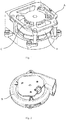
- the fan type applied in the robot vacuum cleaner includes an axial fan A as illustrated in Fig. 1 .
- the axial fan A throws air to the periphery by an electric motor C that drives a rotor impeller B to rotate, thereby generating the suction force.
- the fan type in the robot vacuum cleaner also includes a centrifugal fan D as illustrated in Fig. 2 .
- An air duct structure of the centrifugal fan D is similar to a volute, and the stator impeller is driven to rotate by the motor at a center of the centrifugal fan D, thereby generating the suction force.
- the air duct is mainly formed and defined by a housing of the fan, and the air duct has a poor air outlet guiding performance, this results in a relatively small suction force of the fan, such that the robot vacuum cleaner has a poor cleaning effect and a low efficiency.
- embodiments of the present disclosure provide a fan assembly for a robot vacuum cleaner and a robot vacuum cleaner.
- Embodiments of the present disclosure provide a fan assembly for a robot vacuum cleaner.
- the fan assembly includes an electric motor, a stator impeller, a rotor impeller and a fan cover.
- the stator impeller has a shaft hole, the electric motor is mounted on a side of the stator impeller, and an output shaft of the electric motor passes through the shaft hole.
- the fan cover is mounted on another side of the stator impeller, and an end surface of the fan cover away from the stator impeller defines an air inlet.
- the rotor impeller is mounted to the output shaft of the electric motor and located between the fan cover and the stator impeller.
- the fan cover has a cylindrical shape matching the rotor impeller, the air inlet is circular, and a ratio of a diameter of the air inlet to a diameter of the fan cover or the rotor impeller ranges from 1/5 to 4/5.
- the ratio of the diameter of the air inlet to the diameter of the fan cover is 2/5.
- the stator impeller includes a front impeller disc, a rear impeller disc and a plurality of blades;
- the front impeller disc includes a round plate and a ring rim, the ring rim is disposed around a circumferential edge of the round plate and extends towards the electric motor, and the shaft hole is located in a center of the round plate;
- the rear impeller disc includes a bottom plate and a first protruding rim, the bottom plate defines a first round hole at a middle thereof, the first protruding rim is disposed on the bottom plate along a circumferential edge of the first round hole and extends towards the fan cover; and the plurality of blades is fixed between the ring rim and the first protruding rim and spaced from one another, and gaps among the plurality of blades form a plurality of air-guiding passages.
- the fan assembly further includes a first fastener
- the electric motor has a first mounting hole
- the round plate has a second mounting hole corresponding to the first mounting hole
- the first fastener passes through the first mounting hole and the second mounting hole to fasten the electric motor to the side of the stator impeller.
- the fan cover is fitted over an outside of the first protruding rim, and the fan cover is in interference fit with the first protruding rim.
- the fan assembly further includes a support seat and a second fastener, the stator impeller is mounted on the support seat;
- the support seat includes a base plate and a first leg, the base plate defines a second round hole at a middle thereof, the base plate is provided with the first leg at two ends of the second round hole along the radial direction of the second round hole respectively;
- the rear impeller disc further includes a second leg provided at two ends of the first round hole along a radial direction of the first round hole respectively, the second fastener passes through the first leg and the second leg to fasten the stator impeller to the support seat.
- the first leg is provided with a bump
- the second leg defines a groove matching the bump
- the bump extends into the groove
- the rear impeller disc further includes a second protruding rim, the second protruding rim is disposed on the bottom plate along the circumferential edge of the first round hole and extends towards the electric motor; and the base plate defines an annular groove matching the second protruding rim along a circumferential edge of the second round hole, and the second protruding rim is snapped into the annular groove.
- Embodiments of the present disclosure further provide a robot vacuum cleaner, and the robot vacuum cleaner includes the above-described fan assembly for the robot vacuum cleaner.
- Embodiments of the present disclosure provide the fan assembly for the robot vacuum cleaner and the robot vacuum cleaner, the electric motor is used to provide power to enable the output shaft of the electric motor to drive the rotor impeller to rotate, such that the air entering the fan cover from the air inlet is thrown to a periphery of the rotor impeller to generate a suction force.
- the air flow thrown to the periphery of the rotor impeller flows to an outlet along the gaps among the blades of the stator impeller.
- the stator impeller can effectively guide the air flow to make the fan has a more smooth air outlet and a prominent airflow direction, thereby improving the suction force and the dust suction effect of the fan.
- electric motor 10 output shaft 11; first mounting hole 12; stator impeller 20; round plate 21; blade 22; bottom plate 23; second leg 24; shaft hole 25; second mounting hole 26; first protruding rim 27; second protruding rim 201; first round hole 28; ring rim 29; rotor impeller 30; fan cover 40; air inlet 41; support seat 50; base plate 51; first leg 52; bump 53; second round hole 54; annular groove 55; wire-running notch 60.
- the terms “mounted,” “connected,” “coupled,” “fixed” and the like are used broadly, and may be, for example, fixed connections, detachable connections, or integral connections; may also be mechanical or electrical connections; may also be direct connections or indirect connections via intervening structures; may also be inner communications of two elements.
- the above terms can be understood by those skilled in the art according to specific situations.
- Embodiments of a first aspect of the present disclosure provide a fan assembly for a robot vacuum cleaner, as illustrated in Figs. 3 to 5 .
- the fan assembly for the robot vacuum cleaner of the embodiment of the present disclosure includes an electric motor 10, a stator impeller 20, a rotor impeller 30 and a fan cover 40.
- the stator impeller 20 defines a shaft hole 25, the electric motor 10 is mounted on a side of the stator impeller 20, and an output shaft 11 of the electric motor 10 passes through the shaft hole 25.
- the fan cover 40 is mounted on another side of the stator impeller 20, and an end surface of the fan cover 40 away from the stator impeller 20 defines an air inlet 41.
- the rotor impeller 30 is mounted to the output shaft 11 of the electric motor 10 and located between the fan cover 40 and the stator impeller 20.
- the output shaft 11 of the electric motor 10 passes through the shaft hole 25 located in a center of the stator impeller 20 and is connected to a center of the rotor impeller 30 so as to drive the rotor impeller 30 to rotate.
- An outer diameter of the shaft hole 25 is greater than an outer diameter of the output shaft 11.
- An end surface of the fan cover 40 is mounted on the stator impeller 20 and another end surface thereof defines the air inlet 41.
- the rotor impeller 30 is disposed in the fan cover 40 and located between the air inlet 41 and the rotor impeller 30.
- a size of the fan cover 40 just needs to be slightly greater than that of the rotor impeller 30, and structure among respective components of the fan assembly is compact, which can effectively reduce a height of the fan assembly, thereby better meet small height requirement of the robot vacuum cleaner.
- the stator impeller 20 guides the air flow entering the fan assembly, which effectively promotes vacuum degree and suction force of the fan assembly.
- the fan cover 40 has a cylindrical shape matching the rotor impeller 30, the air inlet 41 is circular, and a ratio of a diameter of the air inlet 41 to a diameter of the fan cover 40 or the rotor impeller 30 ranges from 1/5 to 4/5. Further, the ratio of the diameter of the air inlet 41 to the diameter of the fan cover 40 is 2/5.
- Fig. 4 exemplarily shows a sectional view of an alternative structure of the fan assembly for the robot vacuum cleaner.
- the diameter of the air inlet is 28 mm
- the diameter of the fan cover 40 is 69 mm
- the air inlet 41, the fan cover 40, the rotor impeller 30, the stator impeller 20 and the electric motor 10 all are coaxially disposed.
- the stator impeller 20 includes a front impeller disc, a rear impeller disc and a plurality of blades 22.
- the front impeller disc includes a round plate 21 and a ring rim 29, the ring rim 29 is disposed around a circumferential edge of the round plate 21 and extends towards the electric motor 10, and the shaft hole 25 is located in a center of the round plate 21.
- the rear impeller disc includes a bottom plate 23 and a first protruding rim 27, the bottom plate 23 defines a first round hole 28 at a middle thereof, and the first protruding rim 27 is disposed on the bottom plate 23 along a circumferential edge of the first round hole 28 and extends towards a direction of the fan cover 40.
- the plurality of blades 22 is fixed between the ring rim 29 and the first protruding rim 27 and spaced from one another, and gaps among the plurality of blades 22 form a plurality of air-guiding passages.
- the airflow entering the fan assembly is discharged from the first round hole 28 under the guiding of the blades 22.
- the plurality of blades 22 is evenly disposed at intervals along an axis of the stator impeller 20, and the number of the blades 22 can be adjusted according to requirements.
- the stator impeller 20 is further provided with a plurality of wire-running notches 60 which facilitates the mounting and positioning of wire harness of the fan assembly.
- Fig. 5 exemplarily shows an exploded view of the fan assembly for the robot vacuum cleaner.
- the wire-running notch 60 of the stator impeller 20 is located on the bottom plate 23.
- the fan assembly for the robot vacuum cleaner further includes a first fastener (not illustrated), the electric motor 10 defines a first mounting hole 12, the round plate 21 defines a second mounting hole 26 corresponding to a first mounting hole 12, and the first fastener passes through the first mounting hole 12 and the second mounting hole 26 to fasten the electric motor 10 to the side of the stator impeller 20.
- a plurality of first fasteners In order to ensure the stability of the connection between the stator impeller 20 and the electric motor 10, a plurality of first fasteners, a plurality of first mounting holes 12 and a plurality of second mounting holes 26 may be provided according to requirements.
- the first fastener includes but is not limited to a bolt and a screw. As illustrated in Fig. 5 , the end surface of the electric motor 10 defines three first mounting holes 12 evenly spaced along the circumferential direction, the front impeller disc 21 defines three second mounting holes 26 along the circumferential direction corresponding to the first mounting holes 12, and the fastener passes through the first mounting hole 12 and the second mounting hole 26 to fix the stator impeller 20 to the electric motor 10.
- the fan cover 40 is fitted over an outside of the first protruding rim 27, and the fan cover 40 is in interference fit with the first protruding rim 27.
- the fan cover 40 is fixed to the stator impeller 20 by the interference fit with the first protruding rim 27.
- the mounting manner is simple and easy.
- the fan assembly for the robot vacuum cleaner further includes a support seat 50 and a second fastener, and the stator impeller 20 is mounted on the support seat 50.
- the support seat 50 includes a base plate 51 and a first leg 52, the base plate 51 defines a second round hole 54 at a middle thereof, and the base plate 51 is provided with the first leg 52 at two ends of the second round hole 54 along a radial direction of the second round hole 54 respectively.
- the rear impeller disc further includes a second leg 24 disposed at two ends of the first round hole 28 along a radial direction of the first round hole 28, and the second fastener passes through the first leg 52 and the second leg 24 to fasten the stator impeller 20 to the support seat 50.
- the support seat 50 is preferably made of a material with the noise and vibration reduction function.
- the support seat 50 is a rubber member.
- the support seat 50 can absorb acoustic wave and reduce the vibration and noise.
- the support seat 50 may also be provided with the wire-running notch 60 according to requirements.
- the second fastener includes but is not limited to the bolt and the screw. As illustrated in Fig.
- three wire-running notches 60 are provided and spaced along a circumferential direction of the base plate 51, the electric motor 10 passes through the second round hole 54 and connect to the stator impeller 20, and the support seat 50 surrounds a periphery of the electric motor 10, thereby facilitating the improvement of the noise reduction effect.
- the first leg 52 is provided with a bump 53
- the second leg 24 defines a groove matching the bump 53
- the bump 53 extends into the groove.
- Fig. 5 exemplarily shows the exploded view of an alternative structure of the fan assembly for the robot vacuum cleaner.
- Each first leg 52 is provided with one bump 53, and the bump 53 protrudes towards the stator impeller 20.
- the rear impeller disc further includes a second protruding rim 201, and the second protruding rim 201 is disposed on the bottom plate 23 along the circumferential edge of the first round hole 28 and extends towards the direction of the electric motor 10.
- the base plate 51 defines an annular groove 55 matching the second protruding rim 201 along the circumferential edge of the second round hole 54, and the second protruding rim 201 is snapped into the annular groove 55.
- the second protruding rim 201 is snapped into the annular groove 55, such that not only the fitting of the stator impeller 20 and the support seat 50 can be more compact, but also the sealing effect can be improved, effusion of the airflow within the fan assembly can be reduced, and the suction force of the fan assembly can be promoted.
- the robot vacuum cleaner according to embodiments of a second aspect of the present disclosure includes the fan assembly for the robot vacuum cleaner of the above embodiments. Since the fan assembly for the robot vacuum cleaner according to embodiments of the present disclosure has the above-described effect, the robot vacuum cleaner according to embodiments of the present disclosure also has the corresponding technical effect, i.e. the structure is compact.
- the stator impeller 20 can effectively guide the air flow to make the fan has a more smooth air outlet and a prominent airflow direction, thereby improving the suction force of the fan assembly and ground suction effect and ground suction efficiency of the robot vacuum cleaner.
Landscapes
- Engineering & Computer Science (AREA)
- Mechanical Engineering (AREA)
- General Engineering & Computer Science (AREA)
- Structures Of Non-Positive Displacement Pumps (AREA)
- Electric Vacuum Cleaner (AREA)
Abstract
Description
- This application is based on and claims priority to Chinese Patent Application Serial No.
201820837853.4 - The present disclosure relates to vacuum cleaners and their accessories, and more particularly to a fan assembly for a robot vacuum cleaner and a robot vacuum cleaner.
- With the diversification of the cleaning manners, a robot vacuum cleaner appears in more and more families. The operation manner of the robot vacuum cleaner is mainly divided into "suction" and "sweep". Similar to a traditional vacuum cleaner, the "suction" of the robot vacuum cleaner cannot do without a fan, and a structure of the fan is closely related to magnitude of a "suction force". Generally, the fan type applied in the robot vacuum cleaner includes an axial fan A as illustrated in
Fig. 1 . The axial fan A throws air to the periphery by an electric motor C that drives a rotor impeller B to rotate, thereby generating the suction force. The fan type in the robot vacuum cleaner also includes a centrifugal fan D as illustrated inFig. 2 . An air duct structure of the centrifugal fan D is similar to a volute, and the stator impeller is driven to rotate by the motor at a center of the centrifugal fan D, thereby generating the suction force. In the above fans, the air duct is mainly formed and defined by a housing of the fan, and the air duct has a poor air outlet guiding performance, this results in a relatively small suction force of the fan, such that the robot vacuum cleaner has a poor cleaning effect and a low efficiency. - To address the above-described technical problem, embodiments of the present disclosure provide a fan assembly for a robot vacuum cleaner and a robot vacuum cleaner.
- To this end, a technical solution of the present application is implemented such that:
- Embodiments of the present disclosure provide a fan assembly for a robot vacuum cleaner. The fan assembly includes an electric motor, a stator impeller, a rotor impeller and a fan cover. The stator impeller has a shaft hole, the electric motor is mounted on a side of the stator impeller, and an output shaft of the electric motor passes through the shaft hole. The fan cover is mounted on another side of the stator impeller, and an end surface of the fan cover away from the stator impeller defines an air inlet. The rotor impeller is mounted to the output shaft of the electric motor and located between the fan cover and the stator impeller.
- In the above-described solution, the fan cover has a cylindrical shape matching the rotor impeller, the air inlet is circular, and a ratio of a diameter of the air inlet to a diameter of the fan cover or the rotor impeller ranges from 1/5 to 4/5.
- In the above-described solution, the ratio of the diameter of the air inlet to the diameter of the fan cover is 2/5.
- In the above-described solution, the stator impeller includes a front impeller disc, a rear impeller disc and a plurality of blades;
the front impeller disc includes a round plate and a ring rim, the ring rim is disposed around a circumferential edge of the round plate and extends towards the electric motor, and the shaft hole is located in a center of the round plate;
the rear impeller disc includes a bottom plate and a first protruding rim, the bottom plate defines a first round hole at a middle thereof, the first protruding rim is disposed on the bottom plate along a circumferential edge of the first round hole and extends towards the fan cover; and
the plurality of blades is fixed between the ring rim and the first protruding rim and spaced from one another, and gaps among the plurality of blades form a plurality of air-guiding passages. - In the above-described solution, the fan assembly further includes a first fastener, the electric motor has a first mounting hole, the round plate has a second mounting hole corresponding to the first mounting hole, and the first fastener passes through the first mounting hole and the second mounting hole to fasten the electric motor to the side of the stator impeller.
- In the above-described solution, the fan cover is fitted over an outside of the first protruding rim, and the fan cover is in interference fit with the first protruding rim.
- In the above-described solution, the fan assembly further includes a support seat and a second fastener, the stator impeller is mounted on the support seat;
the support seat includes a base plate and a first leg, the base plate defines a second round hole at a middle thereof, the base plate is provided with the first leg at two ends of the second round hole along the radial direction of the second round hole respectively; and
the rear impeller disc further includes a second leg provided at two ends of the first round hole along a radial direction of the first round hole respectively, the second fastener passes through the first leg and the second leg to fasten the stator impeller to the support seat. - In the above-described solution, the first leg is provided with a bump, the second leg defines a groove matching the bump, and the bump extends into the groove.
- In the above-described solution, the rear impeller disc further includes a second protruding rim, the second protruding rim is disposed on the bottom plate along the circumferential edge of the first round hole and extends towards the electric motor; and
the base plate defines an annular groove matching the second protruding rim along a circumferential edge of the second round hole, and the second protruding rim is snapped into the annular groove. - Embodiments of the present disclosure further provide a robot vacuum cleaner, and the robot vacuum cleaner includes the above-described fan assembly for the robot vacuum cleaner.
- Embodiments of the present disclosure provide the fan assembly for the robot vacuum cleaner and the robot vacuum cleaner, the electric motor is used to provide power to enable the output shaft of the electric motor to drive the rotor impeller to rotate, such that the air entering the fan cover from the air inlet is thrown to a periphery of the rotor impeller to generate a suction force. The air flow thrown to the periphery of the rotor impeller flows to an outlet along the gaps among the blades of the stator impeller. The stator impeller can effectively guide the air flow to make the fan has a more smooth air outlet and a prominent airflow direction, thereby improving the suction force and the dust suction effect of the fan.
- Additional aspects and advantages of embodiments of present disclosure will be given in part in the following descriptions, become apparent in part from the following descriptions, or be learned from the practice of the embodiments of the present disclosure.
- These and other aspects and advantages of embodiments of the present disclosure will become apparent and more readily appreciated from the following descriptions made with reference to the drawings, in which:
-
Fig. 1 is a schematic view of an axial fan in the related art; -
Fig. 2 is a schematic view of a centrifugal fan in the related art; -
Fig. 3 is a schematic view of an alternative structure of a fan assembly for a robot vacuum cleaner according to an embodiment of the present disclosure; -
Fig. 4 is a sectional view of an alternative structure of a fan assembly for a robot vacuum cleaner according to an embodiment of the present disclosure; and -
Fig. 5 is an exploded view of an alternative structure of a fan assembly for a robot vacuum cleaner according to an embodiment of the present disclosure. -
electric motor 10;output shaft 11;first mounting hole 12;stator impeller 20;round plate 21;blade 22;bottom plate 23;second leg 24;shaft hole 25;second mounting hole 26;first protruding rim 27;second protruding rim 201;first round hole 28;ring rim 29;rotor impeller 30;fan cover 40;air inlet 41;support seat 50;base plate 51;first leg 52;bump 53;second round hole 54;annular groove 55; wire-runningnotch 60. - In order to make objects, technical solutions and advantages of the embodiments of the present disclosure more clear, the technical solutions of embodiments of the present disclosure will be clearly and completely described below with reference to the accompanying drawings of the embodiments of the present disclosure. Obviously, the embodiments described herein are a part but not all of the embodiments of the present application. Based on the described embodiments of the present disclosure, all other embodiments obtained by those skilled in the art fall into the protection scope of the present application.
- In the specification, it is to be understood that terms such as "upper," "lower," "inner," and "outer" should be construed to refer to the orientation as then described or as shown in the drawings under discussion. These relative terms are for convenience of description and do not require that the present disclosure be constructed or operated in a particular orientation. In addition, terms such as "first" and "second" are used herein for purposes of description and are not intended to indicate or imply relative importance or significance.
- In the present disclosure, unless specified or limited otherwise, the terms "mounted," "connected," "coupled," "fixed" and the like are used broadly, and may be, for example, fixed connections, detachable connections, or integral connections; may also be mechanical or electrical connections; may also be direct connections or indirect connections via intervening structures; may also be inner communications of two elements. The above terms can be understood by those skilled in the art according to specific situations.
- Embodiments of a first aspect of the present disclosure provide a fan assembly for a robot vacuum cleaner, as illustrated in
Figs. 3 to 5 . The fan assembly for the robot vacuum cleaner of the embodiment of the present disclosure includes anelectric motor 10, astator impeller 20, arotor impeller 30 and afan cover 40. Thestator impeller 20 defines ashaft hole 25, theelectric motor 10 is mounted on a side of thestator impeller 20, and anoutput shaft 11 of theelectric motor 10 passes through theshaft hole 25. Thefan cover 40 is mounted on another side of thestator impeller 20, and an end surface of thefan cover 40 away from thestator impeller 20 defines anair inlet 41. Therotor impeller 30 is mounted to theoutput shaft 11 of theelectric motor 10 and located between thefan cover 40 and thestator impeller 20. - In the present embodiment, the
output shaft 11 of theelectric motor 10 passes through theshaft hole 25 located in a center of thestator impeller 20 and is connected to a center of therotor impeller 30 so as to drive therotor impeller 30 to rotate. An outer diameter of theshaft hole 25 is greater than an outer diameter of theoutput shaft 11. An end surface of thefan cover 40 is mounted on thestator impeller 20 and another end surface thereof defines theair inlet 41. Therotor impeller 30 is disposed in thefan cover 40 and located between theair inlet 41 and therotor impeller 30. Thus, a size of thefan cover 40 just needs to be slightly greater than that of therotor impeller 30, and structure among respective components of the fan assembly is compact, which can effectively reduce a height of the fan assembly, thereby better meet small height requirement of the robot vacuum cleaner. Thestator impeller 20 guides the air flow entering the fan assembly, which effectively promotes vacuum degree and suction force of the fan assembly. - In an alternative implementation of the present disclosure, the
fan cover 40 has a cylindrical shape matching therotor impeller 30, theair inlet 41 is circular, and a ratio of a diameter of theair inlet 41 to a diameter of thefan cover 40 or therotor impeller 30 ranges from 1/5 to 4/5. Further, the ratio of the diameter of theair inlet 41 to the diameter of thefan cover 40 is 2/5. - At the same power level of the
electric motor 10, when the ratio of the diameter of theair inlet 41 to the diameter of thefan cover 40 orrotor impeller 30 is 1/5 to 4/5, the suction force of the fan assembly is relatively large.Fig. 4 exemplarily shows a sectional view of an alternative structure of the fan assembly for the robot vacuum cleaner. The diameter of the air inlet is 28 mm, the diameter of thefan cover 40 is 69 mm, and theair inlet 41, thefan cover 40, therotor impeller 30, thestator impeller 20 and theelectric motor 10 all are coaxially disposed. - In another alternative implementation of the present disclosure, the
stator impeller 20 includes a front impeller disc, a rear impeller disc and a plurality ofblades 22. The front impeller disc includes around plate 21 and aring rim 29, thering rim 29 is disposed around a circumferential edge of theround plate 21 and extends towards theelectric motor 10, and theshaft hole 25 is located in a center of theround plate 21. The rear impeller disc includes abottom plate 23 and a first protrudingrim 27, thebottom plate 23 defines a firstround hole 28 at a middle thereof, and the first protrudingrim 27 is disposed on thebottom plate 23 along a circumferential edge of the firstround hole 28 and extends towards a direction of thefan cover 40. The plurality ofblades 22 is fixed between thering rim 29 and the first protrudingrim 27 and spaced from one another, and gaps among the plurality ofblades 22 form a plurality of air-guiding passages. - The airflow entering the fan assembly is discharged from the first
round hole 28 under the guiding of theblades 22. The plurality ofblades 22 is evenly disposed at intervals along an axis of thestator impeller 20, and the number of theblades 22 can be adjusted according to requirements. Thestator impeller 20 is further provided with a plurality of wire-runningnotches 60 which facilitates the mounting and positioning of wire harness of the fan assembly.Fig. 5 exemplarily shows an exploded view of the fan assembly for the robot vacuum cleaner. The wire-runningnotch 60 of thestator impeller 20 is located on thebottom plate 23. - In an alternative implementation of the present disclosure, the fan assembly for the robot vacuum cleaner further includes a first fastener (not illustrated), the
electric motor 10 defines a first mountinghole 12, theround plate 21 defines a second mountinghole 26 corresponding to a first mountinghole 12, and the first fastener passes through the first mountinghole 12 and the second mountinghole 26 to fasten theelectric motor 10 to the side of thestator impeller 20. - In order to ensure the stability of the connection between the
stator impeller 20 and theelectric motor 10, a plurality of first fasteners, a plurality of first mountingholes 12 and a plurality of second mounting holes 26 may be provided according to requirements. The first fastener includes but is not limited to a bolt and a screw. As illustrated inFig. 5 , the end surface of theelectric motor 10 defines three first mountingholes 12 evenly spaced along the circumferential direction, thefront impeller disc 21 defines three second mountingholes 26 along the circumferential direction corresponding to the first mounting holes 12, and the fastener passes through the first mountinghole 12 and the second mountinghole 26 to fix thestator impeller 20 to theelectric motor 10. - In another alternative implementation of the present disclosure, the
fan cover 40 is fitted over an outside of the first protrudingrim 27, and thefan cover 40 is in interference fit with the first protrudingrim 27. - As illustrated in
Figs. 3 and5 , thefan cover 40 is fixed to thestator impeller 20 by the interference fit with the first protrudingrim 27. The mounting manner is simple and easy. - In another alternative implementation of the present disclosure, the fan assembly for the robot vacuum cleaner further includes a
support seat 50 and a second fastener, and thestator impeller 20 is mounted on thesupport seat 50. Thesupport seat 50 includes abase plate 51 and afirst leg 52, thebase plate 51 defines a secondround hole 54 at a middle thereof, and thebase plate 51 is provided with thefirst leg 52 at two ends of the secondround hole 54 along a radial direction of the secondround hole 54 respectively. The rear impeller disc further includes asecond leg 24 disposed at two ends of the firstround hole 28 along a radial direction of the firstround hole 28, and the second fastener passes through thefirst leg 52 and thesecond leg 24 to fasten thestator impeller 20 to thesupport seat 50. - The
support seat 50 is preferably made of a material with the noise and vibration reduction function. For example, thesupport seat 50 is a rubber member. As thestator impeller 20 is connected to theelectric motor 10, when theelectric motor 10 is in operation, the vibration will occur on theelectric motor 10 itself or between theelectric motor 10 and thestator impeller 20 to generate the noise. Thesupport seat 50 can absorb acoustic wave and reduce the vibration and noise. In order to facilitate the positioning and mounting of wire harness of the fan assembly, thesupport seat 50 may also be provided with the wire-runningnotch 60 according to requirements. The second fastener includes but is not limited to the bolt and the screw. As illustrated inFig. 3 , three wire-runningnotches 60 are provided and spaced along a circumferential direction of thebase plate 51, theelectric motor 10 passes through the secondround hole 54 and connect to thestator impeller 20, and thesupport seat 50 surrounds a periphery of theelectric motor 10, thereby facilitating the improvement of the noise reduction effect. - In another alternative implementation of the present disclosure, the
first leg 52 is provided with abump 53, thesecond leg 24 defines a groove matching thebump 53, and thebump 53 extends into the groove. - The initial assembly can be completed by extending the
bump 53 into the groove, thereby facilitating the mounting and positioning. The second fastener improves the stability of the connection between the both.Fig. 5 exemplarily shows the exploded view of an alternative structure of the fan assembly for the robot vacuum cleaner. Eachfirst leg 52 is provided with onebump 53, and thebump 53 protrudes towards thestator impeller 20. - In an alternative implementation of the present disclosure, the rear impeller disc further includes a second
protruding rim 201, and the second protrudingrim 201 is disposed on thebottom plate 23 along the circumferential edge of the firstround hole 28 and extends towards the direction of theelectric motor 10. Thebase plate 51 defines anannular groove 55 matching the second protrudingrim 201 along the circumferential edge of the secondround hole 54, and the second protrudingrim 201 is snapped into theannular groove 55. - The second
protruding rim 201 is snapped into theannular groove 55, such that not only the fitting of thestator impeller 20 and thesupport seat 50 can be more compact, but also the sealing effect can be improved, effusion of the airflow within the fan assembly can be reduced, and the suction force of the fan assembly can be promoted. - The robot vacuum cleaner according to embodiments of a second aspect of the present disclosure includes the fan assembly for the robot vacuum cleaner of the above embodiments. Since the fan assembly for the robot vacuum cleaner according to embodiments of the present disclosure has the above-described effect, the robot vacuum cleaner according to embodiments of the present disclosure also has the corresponding technical effect, i.e. the structure is compact. The
stator impeller 20 can effectively guide the air flow to make the fan has a more smooth air outlet and a prominent airflow direction, thereby improving the suction force of the fan assembly and ground suction effect and ground suction efficiency of the robot vacuum cleaner. - Other structures and operations of the robot vacuum cleaner according to embodiments of the present disclosure are appreciable and readily achieved, which thus will not be described in detail herein.
- The above-described are merely preferred embodiments of the present disclosure, which are not intended to limit the protection scope of the present disclosure.
Claims (10)
- A fan assembly for a robot vacuum cleaner, comprising an electric motor, a stator impeller, a rotor impeller and a fan cover; the stator impeller having a shaft hole, the electric motor being mounted on one side of the stator impeller, and an output shaft of the electric motor passing through the shaft hole; the fan cover being mounted on another side of the stator impeller, and an end surface of the fan cover away from the stator impeller being provided with an air inlet; the rotor impeller being mounted on the output shaft of the electric motor and located between the fan cover and the stator impeller.
- The fan assembly according to claim 1, wherein the fan cover has a cylindrical shape matching the rotor impeller, the air inlet is circular, and a ratio of a diameter of the air inlet to a diameter of the fan cover or a diameter of the rotor impeller ranges from 1/5 to 4/5.
- The fan assembly according to claim 2, wherein the ratio of the diameter of the air inlet to the diameter of the fan cover is 2/5.
- The fan assembly according to any one of claims 1 to 3, wherein the stator impeller comprises a front impeller disc, a rear impeller disc, and a plurality of blades;
the front impeller disc comprises a round plate and a ring rim, the ring rim is disposed around a circumferential edge of the round plate and extends towards the electric motor, and the shaft hole is located in a center of the round plate;
the rear impeller disc comprises a bottom plate and a first protruding rim, a middle of the bottom plate is provided with a first round hole , the first protruding rim is disposed on the bottom plate around a circumferential edge of the first round hole and extends towards the fan cover; and
the plurality of blades are fixed between the ring rim and the first protruding rim and spaced from one another, and gaps between the blades form a plurality of air-guiding passages. - The fan assembly according to claim 4, further comprising a first fastener, the electric motor having a first mounting hole, the round plate having a second mounting hole corresponding to the first mounting hole, and the first fastener passing through the first mounting hole and the second mounting hole to fasten the electric motor to a side of the stator impeller.
- The fan assembly according to claim 4 or 5, wherein the fan cover is fitted over an outside of the first protruding rim, and the fan cover is in interference fit with the first protruding rim.
- The fan assembly according to claim 4 or 5, further comprising a support seat and a second fastener, the stator impeller being mounted on the support seat;
the support seat comprising a base plate and a first leg, a middle of the base plate being provided with a second round hole , the base plate being provided with the first leg at two ends of the second round hole along a radial direction of the second round hole respectively; and
the rear impeller disc further comprising a second leg provided at two ends of the first round hole along a radial direction of the first round hole respectively, the second fastener passing through the first leg and the second leg to fasten the stator impeller to the support seat. - The fan assembly according to claim 7, wherein the first leg is provided with a bump, the second leg is provided with a groove matching the bump, and the bump extends into the groove.
- The fan assembly according to claim 7 or 8, wherein the rear impeller disc further comprises a second protruding rim disposed on the bottom plate around the circumferential edge of the first round hole and extends towards the electric motor; and
the base plate is provided with an annular groove matching the second protruding rim along a circumferential edge of the second round hole, and the second protruding rim is snapped into the annular groove. - A robot vacuum cleaner, comprising a fan assembly for a robot vacuum cleaner according to any one of claims 1 to 9.
Applications Claiming Priority (2)
| Application Number | Priority Date | Filing Date | Title |
|---|---|---|---|
| CN201820837853.4U CN208651209U (en) | 2018-05-31 | 2018-05-31 | A kind of fan assembly and sweeping robot of sweeping robot |
| PCT/CN2018/098020 WO2019227659A1 (en) | 2018-05-31 | 2018-08-01 | Fan assembly of floor sweeping robot and floor sweeping robot |
Publications (3)
| Publication Number | Publication Date |
|---|---|
| EP3779203A1 true EP3779203A1 (en) | 2021-02-17 |
| EP3779203A4 EP3779203A4 (en) | 2021-06-30 |
| EP3779203B1 EP3779203B1 (en) | 2023-03-22 |
Family
ID=65779796
Family Applications (1)
| Application Number | Title | Priority Date | Filing Date |
|---|---|---|---|
| EP18920822.6A Active EP3779203B1 (en) | 2018-05-31 | 2018-08-01 | Fan assembly of floor sweeping robot and floor sweeping robot |
Country Status (6)
| Country | Link |
|---|---|
| US (1) | US10557478B2 (en) |
| EP (1) | EP3779203B1 (en) |
| JP (1) | JP7058765B2 (en) |
| KR (1) | KR102396076B1 (en) |
| CN (1) | CN208651209U (en) |
| WO (1) | WO2019227659A1 (en) |
Families Citing this family (9)
| Publication number | Priority date | Publication date | Assignee | Title |
|---|---|---|---|---|
| CN110529431B (en) * | 2019-08-30 | 2024-10-22 | 追觅创新科技(苏州)有限公司 | A motor |
| JP2021065463A (en) * | 2019-10-24 | 2021-04-30 | 株式会社マキタ | Dust collector |
| CN114076449B (en) * | 2020-08-18 | 2023-03-17 | 青岛海尔电冰箱有限公司 | Air-cooled refrigerator utilizing centrifugal fan to supply air |
| CN112168075B (en) * | 2020-09-18 | 2024-09-03 | 宁波富佳实业股份有限公司 | Sweeping robot |
| CN112568803B (en) * | 2020-12-24 | 2025-05-13 | 珠海格力电器股份有限公司 | Robot Vacuum Cleaner |
| CN112576531A (en) * | 2020-12-24 | 2021-03-30 | 珠海格力电器股份有限公司 | Fan structure, fan wind channel subassembly and robot of sweeping floor |
| WO2024062670A1 (en) * | 2022-09-22 | 2024-03-28 | パナソニックIpマネジメント株式会社 | Electric blower |
| CN116291742B (en) * | 2023-03-28 | 2025-11-18 | 沈阳航空航天大学 | A crowned multi-stage turbine air motor |
| US20250072693A1 (en) * | 2023-08-30 | 2025-03-06 | Sharkninja Operating Llc | Robotic Cleaner With Extendable Cleaning Surface |
Family Cites Families (23)
| Publication number | Priority date | Publication date | Assignee | Title |
|---|---|---|---|---|
| GB130157A (en) * | 1918-07-25 | 1919-07-25 | Edwin Rudolph Grote | Improvements in or relating to Rotary Vacuum Pumps. |
| US5296769A (en) * | 1992-01-24 | 1994-03-22 | Electrolux Corporation | Air guide assembly for an electric motor and methods of making |
| US5454690A (en) * | 1994-01-13 | 1995-10-03 | Shop Vac Corporation | Air flow housing |
| DE19951861A1 (en) * | 1998-10-31 | 2000-05-04 | Miele & Cie | Vacuum cleaner fan has bearing pot formed so that components can be mounted in axial direction of fan |
| US7013528B2 (en) * | 2002-01-28 | 2006-03-21 | Bissell Homecare, Inc. | Floor cleaner with dusting |
| US6709229B1 (en) * | 2002-05-07 | 2004-03-23 | Bill Lee | Bi-directional incoming air flow fan |
| NZ597256A (en) * | 2009-08-11 | 2013-11-29 | Resmed Motor Technologies Inc | Single stage, axial symmetric blower and portable ventilator |
| US8317497B2 (en) * | 2010-03-03 | 2012-11-27 | Ametek, Inc. | Motor-fan assembly having a tapered stationary fan with a concave underside |
| US8317496B2 (en) * | 2010-03-03 | 2012-11-27 | Ametek, Inc. | Motor-fan assembly having a tapered fan with a concave underside |
| US9757000B2 (en) * | 2013-12-24 | 2017-09-12 | Samsung Electronics Co., Ltd. | Cleaning device |
| JP6458243B2 (en) * | 2014-04-15 | 2019-01-30 | パナソニックIpマネジメント株式会社 | Electric blower and electric vacuum cleaner using the same |
| EP3015713A1 (en) * | 2014-10-30 | 2016-05-04 | Nidec Corporation | Blower apparatus |
| JP6401075B2 (en) * | 2015-02-20 | 2018-10-03 | 日立アプライアンス株式会社 | Electric blower and vacuum cleaner |
| JP6439538B2 (en) * | 2015-03-27 | 2018-12-19 | 株式会社デンソー | Liquid pump |
| EP3076025B1 (en) * | 2015-04-01 | 2020-08-19 | LG Electronics Inc. | Vacuum suction unit |
| JP6658750B2 (en) * | 2015-05-29 | 2020-03-04 | 日本電産株式会社 | Blowers and vacuum cleaners |
| CN106468286A (en) * | 2015-08-19 | 2017-03-01 | 德昌电机(深圳)有限公司 | Blower fan and its bubbler |
| KR101684166B1 (en) * | 2015-09-03 | 2016-12-07 | 엘지전자 주식회사 | Suction unit |
| JP2018062919A (en) * | 2016-10-14 | 2018-04-19 | 株式会社鷺宮製作所 | Drainage pump |
| JP6765278B2 (en) * | 2016-10-19 | 2020-10-07 | 日立グローバルライフソリューションズ株式会社 | Electric blower and vacuum cleaner equipped with it |
| CN106481588B (en) * | 2016-11-16 | 2018-09-25 | 深圳拓邦股份有限公司 | Dust catcher and wind turbine |
| CN206753946U (en) * | 2017-04-20 | 2017-12-15 | 江苏亿美电器有限公司 | A kind of efficient electric air pump |
| CN206723092U (en) * | 2017-04-28 | 2017-12-08 | 美的集团股份有限公司 | Blower fan and there is its dust catcher |
-
2018
- 2018-05-31 CN CN201820837853.4U patent/CN208651209U/en not_active Expired - Fee Related
- 2018-08-01 JP JP2020564607A patent/JP7058765B2/en active Active
- 2018-08-01 WO PCT/CN2018/098020 patent/WO2019227659A1/en not_active Ceased
- 2018-08-01 EP EP18920822.6A patent/EP3779203B1/en active Active
- 2018-08-01 KR KR1020207032789A patent/KR102396076B1/en active Active
- 2018-09-12 US US16/128,540 patent/US10557478B2/en active Active
Also Published As
| Publication number | Publication date |
|---|---|
| CN208651209U (en) | 2019-03-26 |
| EP3779203A4 (en) | 2021-06-30 |
| US20190368507A1 (en) | 2019-12-05 |
| US10557478B2 (en) | 2020-02-11 |
| JP2021523999A (en) | 2021-09-09 |
| WO2019227659A1 (en) | 2019-12-05 |
| EP3779203B1 (en) | 2023-03-22 |
| KR20200141504A (en) | 2020-12-18 |
| KR102396076B1 (en) | 2022-05-09 |
| JP7058765B2 (en) | 2022-04-22 |
Similar Documents
| Publication | Publication Date | Title |
|---|---|---|
| US10557478B2 (en) | Fan assembly for robot vacuum cleaner and robot vacuum cleaner | |
| EP3376043B1 (en) | Motor fan | |
| US6386839B1 (en) | High performance radiator fan | |
| JP7605580B2 (en) | Electric blower and vacuum cleaner equipped with same | |
| CN114555952B (en) | Electric blower and electric vacuum cleaner equipped with the electric blower | |
| US2486619A (en) | Plastic fan for suction cleaners | |
| JP7145588B2 (en) | Electric blower and vacuum cleaner equipped with the same | |
| JP2022081862A (en) | Electric blower and vacuum cleaner including the same | |
| CN205154744U (en) | Centrifugal turbine fan blade and use its motor and food mixer | |
| US11700980B2 (en) | Electric blower, vacuum cleaner, and hand drying device | |
| TWI648475B (en) | Drum fan, blower fan assembly and fan wheel thereof | |
| CN218563957U (en) | Fan module and host | |
| US20190017514A1 (en) | Impeller, air-sending apparatus, and cleaning machine | |
| JP6758243B2 (en) | Electric blower and vacuum cleaner equipped with it | |
| US8317496B2 (en) | Motor-fan assembly having a tapered fan with a concave underside | |
| CN219654913U (en) | Circular centrifugal axial flow fan | |
| WO2022038816A1 (en) | Electric blower, and electric vacuum cleaner provided with same | |
| KR100420516B1 (en) | Turbo-sirocco fan Assembly | |
| CN223391212U (en) | An outer rotor motor with high heat dissipation efficiency | |
| CN108930659B (en) | Fan with cooling device | |
| JP2022081860A (en) | Electric blower and vacuum cleaner including the same | |
| JP2712651B2 (en) | Electric blower | |
| CN112431776B (en) | Fan and household appliance with heat dissipation design | |
| JPH06123300A (en) | Electric blower for vacuum cleaner | |
| CN213928805U (en) | Low-noise axial air-out type sweeper fan |
Legal Events
| Date | Code | Title | Description |
|---|---|---|---|
| STAA | Information on the status of an ep patent application or granted ep patent |
Free format text: STATUS: THE INTERNATIONAL PUBLICATION HAS BEEN MADE |
|
| PUAI | Public reference made under article 153(3) epc to a published international application that has entered the european phase |
Free format text: ORIGINAL CODE: 0009012 |
|
| STAA | Information on the status of an ep patent application or granted ep patent |
Free format text: STATUS: REQUEST FOR EXAMINATION WAS MADE |
|
| 17P | Request for examination filed |
Effective date: 20201104 |
|
| AK | Designated contracting states |
Kind code of ref document: A1 Designated state(s): AL AT BE BG CH CY CZ DE DK EE ES FI FR GB GR HR HU IE IS IT LI LT LU LV MC MK MT NL NO PL PT RO RS SE SI SK SM TR |
|
| AX | Request for extension of the european patent |
Extension state: BA ME |
|
| A4 | Supplementary search report drawn up and despatched |
Effective date: 20210531 |
|
| RIC1 | Information provided on ipc code assigned before grant |
Ipc: A47L 9/22 20060101AFI20210525BHEP Ipc: F04D 29/44 20060101ALI20210525BHEP Ipc: F04D 29/62 20060101ALI20210525BHEP Ipc: F04D 29/66 20060101ALI20210525BHEP |
|
| DAV | Request for validation of the european patent (deleted) | ||
| DAX | Request for extension of the european patent (deleted) | ||
| RAP1 | Party data changed (applicant data changed or rights of an application transferred) |
Owner name: MIDEA ROBOZONE TECHNOLOGY CO., LTD. |
|
| REG | Reference to a national code |
Ref country code: DE Ref legal event code: R079 Ref document number: 602018047641 Country of ref document: DE Free format text: PREVIOUS MAIN CLASS: F04D0025080000 Ipc: A47L0009220000 |
|
| GRAP | Despatch of communication of intention to grant a patent |
Free format text: ORIGINAL CODE: EPIDOSNIGR1 |
|
| STAA | Information on the status of an ep patent application or granted ep patent |
Free format text: STATUS: GRANT OF PATENT IS INTENDED |
|
| RIC1 | Information provided on ipc code assigned before grant |
Ipc: F04D 29/66 20060101ALI20220930BHEP Ipc: F04D 29/62 20060101ALI20220930BHEP Ipc: F04D 29/44 20060101ALI20220930BHEP Ipc: F04D 29/42 20060101ALI20220930BHEP Ipc: A47L 9/22 20060101AFI20220930BHEP |
|
| INTG | Intention to grant announced |
Effective date: 20221024 |
|
| GRAS | Grant fee paid |
Free format text: ORIGINAL CODE: EPIDOSNIGR3 |
|
| GRAA | (expected) grant |
Free format text: ORIGINAL CODE: 0009210 |
|
| STAA | Information on the status of an ep patent application or granted ep patent |
Free format text: STATUS: THE PATENT HAS BEEN GRANTED |
|
| AK | Designated contracting states |
Kind code of ref document: B1 Designated state(s): AL AT BE BG CH CY CZ DE DK EE ES FI FR GB GR HR HU IE IS IT LI LT LU LV MC MK MT NL NO PL PT RO RS SE SI SK SM TR |
|
| REG | Reference to a national code |
Ref country code: GB Ref legal event code: FG4D |
|
| REG | Reference to a national code |
Ref country code: CH Ref legal event code: EP |
|
| REG | Reference to a national code |
Ref country code: IE Ref legal event code: FG4D |
|
| REG | Reference to a national code |
Ref country code: DE Ref legal event code: R096 Ref document number: 602018047641 Country of ref document: DE |
|
| REG | Reference to a national code |
Ref country code: AT Ref legal event code: REF Ref document number: 1554782 Country of ref document: AT Kind code of ref document: T Effective date: 20230415 |
|
| REG | Reference to a national code |
Ref country code: LT Ref legal event code: MG9D |
|
| P01 | Opt-out of the competence of the unified patent court (upc) registered |
Effective date: 20230615 |
|
| REG | Reference to a national code |
Ref country code: NL Ref legal event code: MP Effective date: 20230322 |
|
| PG25 | Lapsed in a contracting state [announced via postgrant information from national office to epo] |
Ref country code: RS Free format text: LAPSE BECAUSE OF FAILURE TO SUBMIT A TRANSLATION OF THE DESCRIPTION OR TO PAY THE FEE WITHIN THE PRESCRIBED TIME-LIMIT Effective date: 20230322 Ref country code: NO Free format text: LAPSE BECAUSE OF FAILURE TO SUBMIT A TRANSLATION OF THE DESCRIPTION OR TO PAY THE FEE WITHIN THE PRESCRIBED TIME-LIMIT Effective date: 20230622 Ref country code: LV Free format text: LAPSE BECAUSE OF FAILURE TO SUBMIT A TRANSLATION OF THE DESCRIPTION OR TO PAY THE FEE WITHIN THE PRESCRIBED TIME-LIMIT Effective date: 20230322 Ref country code: LT Free format text: LAPSE BECAUSE OF FAILURE TO SUBMIT A TRANSLATION OF THE DESCRIPTION OR TO PAY THE FEE WITHIN THE PRESCRIBED TIME-LIMIT Effective date: 20230322 Ref country code: HR Free format text: LAPSE BECAUSE OF FAILURE TO SUBMIT A TRANSLATION OF THE DESCRIPTION OR TO PAY THE FEE WITHIN THE PRESCRIBED TIME-LIMIT Effective date: 20230322 |
|
| REG | Reference to a national code |
Ref country code: AT Ref legal event code: MK05 Ref document number: 1554782 Country of ref document: AT Kind code of ref document: T Effective date: 20230322 |
|
| PG25 | Lapsed in a contracting state [announced via postgrant information from national office to epo] |
Ref country code: SE Free format text: LAPSE BECAUSE OF FAILURE TO SUBMIT A TRANSLATION OF THE DESCRIPTION OR TO PAY THE FEE WITHIN THE PRESCRIBED TIME-LIMIT Effective date: 20230322 Ref country code: NL Free format text: LAPSE BECAUSE OF FAILURE TO SUBMIT A TRANSLATION OF THE DESCRIPTION OR TO PAY THE FEE WITHIN THE PRESCRIBED TIME-LIMIT Effective date: 20230322 Ref country code: GR Free format text: LAPSE BECAUSE OF FAILURE TO SUBMIT A TRANSLATION OF THE DESCRIPTION OR TO PAY THE FEE WITHIN THE PRESCRIBED TIME-LIMIT Effective date: 20230623 Ref country code: FI Free format text: LAPSE BECAUSE OF FAILURE TO SUBMIT A TRANSLATION OF THE DESCRIPTION OR TO PAY THE FEE WITHIN THE PRESCRIBED TIME-LIMIT Effective date: 20230322 |
|
| PG25 | Lapsed in a contracting state [announced via postgrant information from national office to epo] |
Ref country code: SM Free format text: LAPSE BECAUSE OF FAILURE TO SUBMIT A TRANSLATION OF THE DESCRIPTION OR TO PAY THE FEE WITHIN THE PRESCRIBED TIME-LIMIT Effective date: 20230322 Ref country code: RO Free format text: LAPSE BECAUSE OF FAILURE TO SUBMIT A TRANSLATION OF THE DESCRIPTION OR TO PAY THE FEE WITHIN THE PRESCRIBED TIME-LIMIT Effective date: 20230322 Ref country code: PT Free format text: LAPSE BECAUSE OF FAILURE TO SUBMIT A TRANSLATION OF THE DESCRIPTION OR TO PAY THE FEE WITHIN THE PRESCRIBED TIME-LIMIT Effective date: 20230724 Ref country code: ES Free format text: LAPSE BECAUSE OF FAILURE TO SUBMIT A TRANSLATION OF THE DESCRIPTION OR TO PAY THE FEE WITHIN THE PRESCRIBED TIME-LIMIT Effective date: 20230322 Ref country code: EE Free format text: LAPSE BECAUSE OF FAILURE TO SUBMIT A TRANSLATION OF THE DESCRIPTION OR TO PAY THE FEE WITHIN THE PRESCRIBED TIME-LIMIT Effective date: 20230322 Ref country code: AT Free format text: LAPSE BECAUSE OF FAILURE TO SUBMIT A TRANSLATION OF THE DESCRIPTION OR TO PAY THE FEE WITHIN THE PRESCRIBED TIME-LIMIT Effective date: 20230322 |
|
| PG25 | Lapsed in a contracting state [announced via postgrant information from national office to epo] |
Ref country code: SK Free format text: LAPSE BECAUSE OF FAILURE TO SUBMIT A TRANSLATION OF THE DESCRIPTION OR TO PAY THE FEE WITHIN THE PRESCRIBED TIME-LIMIT Effective date: 20230322 Ref country code: PL Free format text: LAPSE BECAUSE OF FAILURE TO SUBMIT A TRANSLATION OF THE DESCRIPTION OR TO PAY THE FEE WITHIN THE PRESCRIBED TIME-LIMIT Effective date: 20230322 Ref country code: IS Free format text: LAPSE BECAUSE OF FAILURE TO SUBMIT A TRANSLATION OF THE DESCRIPTION OR TO PAY THE FEE WITHIN THE PRESCRIBED TIME-LIMIT Effective date: 20230722 |
|
| REG | Reference to a national code |
Ref country code: DE Ref legal event code: R097 Ref document number: 602018047641 Country of ref document: DE |
|
| PLBE | No opposition filed within time limit |
Free format text: ORIGINAL CODE: 0009261 |
|
| STAA | Information on the status of an ep patent application or granted ep patent |
Free format text: STATUS: NO OPPOSITION FILED WITHIN TIME LIMIT |
|
| PG25 | Lapsed in a contracting state [announced via postgrant information from national office to epo] |
Ref country code: SI Free format text: LAPSE BECAUSE OF FAILURE TO SUBMIT A TRANSLATION OF THE DESCRIPTION OR TO PAY THE FEE WITHIN THE PRESCRIBED TIME-LIMIT Effective date: 20230322 Ref country code: DK Free format text: LAPSE BECAUSE OF FAILURE TO SUBMIT A TRANSLATION OF THE DESCRIPTION OR TO PAY THE FEE WITHIN THE PRESCRIBED TIME-LIMIT Effective date: 20230322 Ref country code: CZ Free format text: LAPSE BECAUSE OF FAILURE TO SUBMIT A TRANSLATION OF THE DESCRIPTION OR TO PAY THE FEE WITHIN THE PRESCRIBED TIME-LIMIT Effective date: 20230322 |
|
| 26N | No opposition filed |
Effective date: 20240102 |
|
| PG25 | Lapsed in a contracting state [announced via postgrant information from national office to epo] |
Ref country code: MC Free format text: LAPSE BECAUSE OF FAILURE TO SUBMIT A TRANSLATION OF THE DESCRIPTION OR TO PAY THE FEE WITHIN THE PRESCRIBED TIME-LIMIT Effective date: 20230322 |
|
| REG | Reference to a national code |
Ref country code: CH Ref legal event code: PL |
|
| PG25 | Lapsed in a contracting state [announced via postgrant information from national office to epo] |
Ref country code: MC Free format text: LAPSE BECAUSE OF FAILURE TO SUBMIT A TRANSLATION OF THE DESCRIPTION OR TO PAY THE FEE WITHIN THE PRESCRIBED TIME-LIMIT Effective date: 20230322 |
|
| PG25 | Lapsed in a contracting state [announced via postgrant information from national office to epo] |
Ref country code: LU Free format text: LAPSE BECAUSE OF NON-PAYMENT OF DUE FEES Effective date: 20230801 |
|
| PG25 | Lapsed in a contracting state [announced via postgrant information from national office to epo] |
Ref country code: LU Free format text: LAPSE BECAUSE OF NON-PAYMENT OF DUE FEES Effective date: 20230801 Ref country code: CH Free format text: LAPSE BECAUSE OF NON-PAYMENT OF DUE FEES Effective date: 20230831 |
|
| REG | Reference to a national code |
Ref country code: BE Ref legal event code: MM Effective date: 20230831 |
|
| REG | Reference to a national code |
Ref country code: IE Ref legal event code: MM4A |
|
| PG25 | Lapsed in a contracting state [announced via postgrant information from national office to epo] |
Ref country code: IT Free format text: LAPSE BECAUSE OF FAILURE TO SUBMIT A TRANSLATION OF THE DESCRIPTION OR TO PAY THE FEE WITHIN THE PRESCRIBED TIME-LIMIT Effective date: 20230322 |
|
| PG25 | Lapsed in a contracting state [announced via postgrant information from national office to epo] |
Ref country code: IE Free format text: LAPSE BECAUSE OF NON-PAYMENT OF DUE FEES Effective date: 20230801 |
|
| PG25 | Lapsed in a contracting state [announced via postgrant information from national office to epo] |
Ref country code: IE Free format text: LAPSE BECAUSE OF NON-PAYMENT OF DUE FEES Effective date: 20230801 |
|
| PG25 | Lapsed in a contracting state [announced via postgrant information from national office to epo] |
Ref country code: BE Free format text: LAPSE BECAUSE OF NON-PAYMENT OF DUE FEES Effective date: 20230831 |
|
| PG25 | Lapsed in a contracting state [announced via postgrant information from national office to epo] |
Ref country code: BG Free format text: LAPSE BECAUSE OF FAILURE TO SUBMIT A TRANSLATION OF THE DESCRIPTION OR TO PAY THE FEE WITHIN THE PRESCRIBED TIME-LIMIT Effective date: 20230322 |
|
| PG25 | Lapsed in a contracting state [announced via postgrant information from national office to epo] |
Ref country code: BG Free format text: LAPSE BECAUSE OF FAILURE TO SUBMIT A TRANSLATION OF THE DESCRIPTION OR TO PAY THE FEE WITHIN THE PRESCRIBED TIME-LIMIT Effective date: 20230322 |
|
| PG25 | Lapsed in a contracting state [announced via postgrant information from national office to epo] |
Ref country code: CY Free format text: LAPSE BECAUSE OF FAILURE TO SUBMIT A TRANSLATION OF THE DESCRIPTION OR TO PAY THE FEE WITHIN THE PRESCRIBED TIME-LIMIT; INVALID AB INITIO Effective date: 20180801 |
|
| PG25 | Lapsed in a contracting state [announced via postgrant information from national office to epo] |
Ref country code: HU Free format text: LAPSE BECAUSE OF FAILURE TO SUBMIT A TRANSLATION OF THE DESCRIPTION OR TO PAY THE FEE WITHIN THE PRESCRIBED TIME-LIMIT; INVALID AB INITIO Effective date: 20180801 |
|
| PGFP | Annual fee paid to national office [announced via postgrant information from national office to epo] |
Ref country code: DE Payment date: 20250827 Year of fee payment: 8 |
|
| PGFP | Annual fee paid to national office [announced via postgrant information from national office to epo] |
Ref country code: GB Payment date: 20250826 Year of fee payment: 8 |
|
| PGFP | Annual fee paid to national office [announced via postgrant information from national office to epo] |
Ref country code: FR Payment date: 20250826 Year of fee payment: 8 |
|
| PG25 | Lapsed in a contracting state [announced via postgrant information from national office to epo] |
Ref country code: TR Free format text: LAPSE BECAUSE OF FAILURE TO SUBMIT A TRANSLATION OF THE DESCRIPTION OR TO PAY THE FEE WITHIN THE PRESCRIBED TIME-LIMIT Effective date: 20230322 |