EP3779168B1 - Auto-choke device of carburetor - Google Patents
Auto-choke device of carburetor Download PDFInfo
- Publication number
- EP3779168B1 EP3779168B1 EP18913168.3A EP18913168A EP3779168B1 EP 3779168 B1 EP3779168 B1 EP 3779168B1 EP 18913168 A EP18913168 A EP 18913168A EP 3779168 B1 EP3779168 B1 EP 3779168B1
- Authority
- EP
- European Patent Office
- Prior art keywords
- choke
- lever
- main body
- engine
- wax
- Prior art date
- Legal status (The legal status is an assumption and is not a legal conclusion. Google has not performed a legal analysis and makes no representation as to the accuracy of the status listed.)
- Active
Links
- 230000033001 locomotion Effects 0.000 claims description 16
- 239000000446 fuel Substances 0.000 description 25
- 239000000203 mixture Substances 0.000 description 9
- 238000010792 warming Methods 0.000 description 6
- 238000002485 combustion reaction Methods 0.000 description 4
- 238000001514 detection method Methods 0.000 description 2
- 239000002828 fuel tank Substances 0.000 description 2
- 230000037431 insertion Effects 0.000 description 2
- 238000003780 insertion Methods 0.000 description 2
- 239000000463 material Substances 0.000 description 2
- 238000002791 soaking Methods 0.000 description 2
- 239000007858 starting material Substances 0.000 description 2
- 238000011144 upstream manufacturing Methods 0.000 description 2
- 238000009834 vaporization Methods 0.000 description 2
- 230000008016 vaporization Effects 0.000 description 2
- 230000005540 biological transmission Effects 0.000 description 1
- 230000008602 contraction Effects 0.000 description 1
- 238000001816 cooling Methods 0.000 description 1
- 230000000694 effects Effects 0.000 description 1
- 230000003993 interaction Effects 0.000 description 1
- 230000009191 jumping Effects 0.000 description 1
- 230000000149 penetrating effect Effects 0.000 description 1
- 230000002265 prevention Effects 0.000 description 1
- 230000001105 regulatory effect Effects 0.000 description 1
Images


Classifications
-
- F—MECHANICAL ENGINEERING; LIGHTING; HEATING; WEAPONS; BLASTING
- F02—COMBUSTION ENGINES; HOT-GAS OR COMBUSTION-PRODUCT ENGINE PLANTS
- F02M—SUPPLYING COMBUSTION ENGINES IN GENERAL WITH COMBUSTIBLE MIXTURES OR CONSTITUENTS THEREOF
- F02M1/00—Carburettors with means for facilitating engine's starting or its idling below operational temperatures
- F02M1/08—Carburettors with means for facilitating engine's starting or its idling below operational temperatures the means to facilitate starting or idling becoming operative or inoperative automatically
- F02M1/10—Carburettors with means for facilitating engine's starting or its idling below operational temperatures the means to facilitate starting or idling becoming operative or inoperative automatically dependent on engine temperature, e.g. having thermostat
-
- F—MECHANICAL ENGINEERING; LIGHTING; HEATING; WEAPONS; BLASTING
- F02—COMBUSTION ENGINES; HOT-GAS OR COMBUSTION-PRODUCT ENGINE PLANTS
- F02M—SUPPLYING COMBUSTION ENGINES IN GENERAL WITH COMBUSTIBLE MIXTURES OR CONSTITUENTS THEREOF
- F02M7/00—Carburettors with means for influencing, e.g. enriching or keeping constant, fuel/air ratio of charge under varying conditions
- F02M7/12—Other installations, with moving parts, for influencing fuel/air ratio, e.g. having valves
Definitions
- the present invention relates to an automatic choke device of a carburetor provided in an engine.
- an automatic choke device that automatically opens and closes a choke valve of a carburetor in accordance with a temperature of an engine main body, thereby facilitating starting of an engine, particularly, starting at a low temperature.
- an automatic choke device described in JP-A-2006-037804 includes a wax that is attached to an engine main body, a rod that performs a linear motion in conjunction with thermal expansion of the wax, a choke lever that rotates in conjunction with the linear motion of the rod, and a choke shaft that is arranged so as to be able to abut against the choke lever and connected to a choke valve of a carburetor.
- JP S58 44257 A discloses a lever arrangement with a fixed choke arm and a choke lever rotatable supported by a choke valve shaft and provided with a flat portion and a circular arc portion.
- the choke valve is opened and closed by an interaction of a choke arm and a spring.
- JP S57 200651 A proposes a choke lever arrangement comprising two choke levers rotating around a choke shaft. Both provided with a flat portion, wherein one choke lever includes a circular arc portion. According to the related art, a complex lever arrangement is necessary to handle the overstroke of wax at least partially.
- the choke lever since the choke lever includes two lever members that can be individually rotated, and a connecting spring that connects the two lever members, and the overstroke of the wax is absorbed by expansion of the connecting spring, the number of components increases, and an excessive stress acts on a support portion of the connecting spring, so that it is necessary to increase rigidity of the lever member or the like.
- the present invention provides an automatic choke device of a carburetor that can suppress the number of components and appropriately absorb overstroke of a wax.
- an engine comprising an engine main body and a carburetor, the carburetor comprising an automatic choke device including:
- the automatic choke device for a carburetor that can suppress the number of components and appropriately absorb the overstroke of the wax.
- An engine E of the present embodiment is a small-sized general-purpose engine mounted on a walk-behind lawn mower or the like, and includes an OHV vertical engine as an engine main body 1.
- an axial center direction of a crankshaft 11 is defined as an upper-lower direction
- a direction in which a piston 13 slides back and forth is defined as a front-rear direction, which is orthogonal to the upper-lower direction
- a direction orthogonal to the upper-lower direction and the front-rear direction is defined as a left-right direction.
- a front side of the engine E is shown as Fr
- a rear side thereof is shown as Rr
- a left side thereof is shown as L
- a right side thereof is shown as R
- an upper side thereof is shown as U
- a lower side thereof is shown as D.
- the engine E of the present embodiment includes the engine main body 1, a fan 2 for cooling that is arranged above the engine main body 1 and also functions as a flywheel, a fan cover 3 that accommodates the fan 2, a recoil starter 4 that is arranged above the fan 2 and performs a starting operation of the engine main body 1, a top cover 5 that covers at least upper portions of the engine main body 1, the fan 2, the fan cover 3, and the recoil starter 4, a fuel tank 6 that stores fuel in the engine main body 1, an air cleaner 7 that purifies intake air from the engine main body 1, and a muffler 8 that exhausts exhaust gas of the engine main body 1 while muffling the exhaust gas.
- the engine main body 1 includes an engine block 10 having a crankcase portion 10a and a cylinder portion 10b, the crankshaft 11 that is rotatably supported by the crankcase portion 10a in an upper-lower direction, the piston 13 that is slidably fitted in the cylinder portion 10b and connected to the crankshaft 11 via a connecting rod 12, an intake valve 14 that is provided on a head portion 10c of the cylinder portion 10b, an exhaust valve 15, a spark plug 16, a head cover 17 that covers the head portion 10c of the cylinder portion 10b, a valve-operating mechanism 18 that operates the intake valve 14 and the exhaust valve 15 in accordance with a rotation of the crankshaft 11, a carburetor 22 that generates an air-fuel mixture of fuel and air and supplies the air-fuel mixture into the cylinder portion 10b, a governor device 23 that automatically opens and closes a throttle valve (not shown) of the carburetor 22 in accordance with a rotational speed (the number of rotations) of the crankshaft 11, and an automatic choke
- the engine block 10 of the present embodiment is divided into three parts including a crankcase main body 19 that includes a bottom portion 19b having a first crankshaft insertion hole 19a, and a tubular portion 19d in which the bottom portion 19b is integrally formed at a lower end portion thereof and a case opening portion 19c is provided at an upper end portion thereof, a crankcase cover 20 that has a second crankshaft insertion hole 20a, and covers the case opening portion 19c of the crankcase main body 19, and a cylinder unit 21 that extends forward from the tubular portion 19d of the crankcase main body 19.
- crankcase main body 19 and the crankcase cover 20 configure the crankcase portion 10a
- the cylinder unit 21 configures the cylinder portion 10b
- a configuration of the engine block 10 is not limited to that of the present embodiment, and can be changed as appropriate.
- the carburetor 22 includes a carburetor main body 26 having an intake passage 26a penetrating in the left-right direction, the choke valve 24 arranged on an upstream side of the intake passage 26a, and the throttle valve (not shown) arranged on a downstream side of the intake passage 26a.
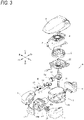
- the carburetor main body 26 is attached to the cylinder portion 10b of the engine main body 1 such that a downstream side opening portion of the intake passage 26a communicates with an intake port 10d of the engine main body 1 (see FIG. 3 ), and an upstream side opening portion of the intake passage 26a is connected to the air cleaner 7.
- the carburetor main body 26 includes a fuel supply portion 26b to which fuel is supplied from the fuel tank 6 via a fuel tube 27, and the fuel supply portion 26b communicates with a fuel nozzle (not shown) that opens into the intake passage 26a between the choke valve 24 and the throttle valve.
- the outside air is sucked into the intake passage 26a of the carburetor main body 26 through the air cleaner 7, the sucked air sucks out the fuel from the fuel nozzle to become the air-fuel mixture of air and fuel, and the air-fuel mixture is supplied to the cylinder portion 10b of the engine main body 1.
- the choke valve 24 and the throttle valve are butterfly type valve bodies that are rotatably supported by the carburetor main body 26 via valve shafts 28, 29 extending in the upper-lower direction.
- the throttle valve is a valve for adjusting an amount of the air-fuel mixture to be supplied to the engine main body 1, is kept in a fully open position before the engine main body 1 is started, and is controlled to a closing side so as to maintain a predetermined engine speed by the governor device 23 when the engine main body 1 is started.
- the choke valve 24 is a valve for adjusting a ratio of air and fuel in the air-fuel mixture.
- the choke valve 24 is connected to the automatic choke device 25 via the valve shaft 28, and an opening degree thereof is automatically controlled in accordance with the change in the temperature of the engine main body 1.
- the governor device 23 includes a rotational speed detection unit 30 that is arranged in the crankcase portion 10a of the engine main body 1 and detects the rotational speed (the number of rotations) of the crankshaft 11, a governor lever 31 that is integrally provided on an upper end portion of the valve shaft 29 of the throttle valve, and a rotational speed transmission portion 32 that takes out the rotational speed of the crankshaft 11 detected by the rotational speed detection portion 30 as a rotation change of an arm member 32a and transmits the rotational speed to the governor lever 31 via a rod member 32b.
- the rod member 32b is connected to one end portion of the arm member 32a, is pulled rearward by an urging force of an arm return spring 32c connected to the other end portion of the arm member 32a when the engine is stopped, and is pushed forward in accordance with an increase in the rotational speed of the crankshaft 11 after the engine is started.
- the rod member 32b is connected to one end portion 31a of the governor lever 31, and when the engine is stopped, the one end portion 31a is pulled rearward by the rod member 32b to rotate the valve shaft 29 in a direction in which the throttle valve opens.
- a governor stopper 26c for regulating a rotation of the governor lever 31 in an opening direction is provided in a protruding manner on an upper portion of the carburetor main body 26, and when the engine is stopped, a stopper engaging portion 3 1b of the governor lever 31 is engaged with the governor stopper 26c to keep the throttle valve in a fully open state.
- the governor lever 31 pushes the one end portion 31a forward by the rod member 32b in accordance with the rotational speed of the crankshaft 11 to rotate the valve shaft 29 in a direction of closing the throttle valve, thereby maintaining a predetermined engine speed.
- the automatic choke device 25 includes a wax 41 that is attached to the engine main body 1, a rod 43 that is connected to the wax 41 via a retainer 42 and performs a linear motion (jumping operation) in conjunction with thermal expansion of the wax 41, a rod return spring 44 that pushes back the retainer 42 and the rod 43 in conjunction with thermal contraction of the wax 41, a choke lever 45 that rotates in conjunction with the linear motion of the rod 43, a holding member 46 that supports the rod 43 and the choke lever 45, a choke shaft 47 that is arranged so as to be able to abut against the choke lever 45 and connected to the choke valve 24 of the carburetor 22, and a shaft return spring 48 that urges the choke shaft 47 in the direction of closing the choke valve 24.
- a wax 41 that is attached to the engine main body 1
- a rod 43 that is connected to the wax 41 via a retainer 42 and performs a linear motion (jumping operation) in conjunction with thermal expansion of the wax 41
- a rod return spring 44 that pushes back
- the automatic choke device 25 of the present embodiment includes the wax 41 that thermally expands in accordance with temperature rise of the engine main body 1.
- the choke valve 24 of the carburetor 22 is maintained on the closing side to facilitate the starting of the engine main body 1, while after the engine is started, the choke valve 24 of the carburetor 22 is controlled to an opening side by the thermal expansion of the wax 41 in accordance with the temperature rise of the engine main body 1.
- the automatic choke device 25 since overstroke occurs in which the wax 41 continues the thermal expansion even after the choke valve 24 is fully opened, it is necessary to absorb the overstroke of the wax 41.
- a configuration of each portion of the automatic choke device 25 will be described with reference to FIGs. 6 to 8 .
- the wax 41 is a heat-sensitive actuator that encloses a heat-sensitive material whose volume changes in accordance with a change in the temperature, expands and contracts in accordance with a change in the volume of the heat-sensitive material, and is configured to thermally expand in a length direction as the temperature rises and thermally contract in the length direction as the temperature falls.
- the wax 41 of the present embodiment is arranged at a side surface of the cylinder portion 10b of the engine main body 1, that is, closer the crankcase portion 10a side than the intake port 10d, avoiding a position in the vicinity of the intake port 10d (see FIG. 3 ).
- a tubular portion 10e is provided in a protruding manner on a side surface of the cylinder portion 10b of the engine main body 1, and the wax 41 is accommodated in the tubular portion 10e.
- the temperature of the wax 41 may deviate from a temperature in a combustion chamber at the time of soaking after the engine is stopped, but a temperature rise characteristic of the wax 41 can be made close to a temperature characteristic of the combustion chamber by arranging the wax 41 on the side surface of the cylinder portion 10b of the engine main body 1, that is, at a position separated from the intake port 10d.
- the holding member 46 integrally includes an attachment portion 46a that is attached to the engine main body 1, a tubular rod support portion 46b that supports the rod 43 so as to be movable in the left-right direction, and a choke lever support portion 46c that rotatably supports the choke lever 45 via a pin 49. According to such a holding member 46, the number of components can be reduced as compared with a case where a holding member for supporting the rod 43 that performs a linear motion and a holding member for supporting the choke lever 45 that performs a rotating motion are separately provided.
- the attachment portion 46a of the holding member 46 is sandwiched between the carburetor 22 and the engine main body 1, and is fixed and fastened together with the carburetor 22 and the engine main body 1 by a bolt (not shown) that fastens the carburetor 22 to the engine main body 1.
- a bolt (not shown) that fastens the carburetor 22 to the engine main body 1.
- the rod 43 integrally includes a rod main body 43a that is supported by the rod support portion 46b of the holding member 46 so as to be movable in the left-right direction, a retainer connecting portion 43b that is provided at a base end portion of the rod main body 43a and is connected to the retainer 42, and a choke lever connecting portion 43c that is provided at a distal end portion of the rod main body 43a and connected to the choke lever 45.
- the choke lever connecting portion 43c includes an upward extending portion 43d that extends upward from a distal end of the rod main body 43a and is inserted into a rod connecting hole 45b of the choke lever 45 to interlock the choke lever 45 with a linear motion of the rod 43 in a pushing direction and a pulling direction, and a coming-off prevention portion 43e that extends outward from an upper end of the upward extending portion 43d and prevents the upward extending portion 43d from coming off.
- the choke lever 45 includes a choke lever main body 45a that is rotatably supported by the choke lever support portion 46c of the holding member 46 via the pin 49, a rod connecting hole 45b that is formed in the vicinity of a rotation center (pin 49) of the choke lever main body 45a and is connected to the rod 43, a flat portion 45c that engages with a choke lever engaging portion 47d of the choke shaft 47, and a circular arc portion 45d that is formed in a circular arc shape so as to be continuous (a circular arc shape with a rotation center of the choke lever 45 as a circular arc center) from the flat portion 45c and is brought into sliding contact with the choke lever engaging portion 47d of the choke shaft 47.
- one choke lever 45 can be substituted for an automatic choke operation performed by two lever members and one connecting spring in an automatic choke device in the related art, so that the number of components can be reduced.
- the flat portion 45c of the choke lever 45 engages with the choke lever engaging portion 47d of the choke shaft 47 to rotate the choke shaft 47, so that the choke valve 24 can be opened in conjunction with the expansion of the wax 41.
- the circular arc portion 45d of the choke lever 45 is brought into sliding contact with the choke lever engaging portion 47d of the choke shaft 47, so that the overstroke of the wax 41 is absorbed without rotating the choke shaft 47.
- the choke lever 45 of the present embodiment is a plate-shaped member, and the flat portion 45c and the circular arc portion 45d are provided on a side surface of the plate-shaped member. According to such a choke lever 45, the choke lever 45 can be reduced in a size by setting the flat portion 45c and the circular arc portion 45d of the choke lever 45 on the side surface of the plate-shaped member having high rigidity.
- the choke shaft 47 includes a choke shaft main body 47a that is integrally provided on an upper end portion of the valve shaft 28 of the choke valve 24 and is urged by the shaft return spring 48 in a direction of closing the choke valve 24, a first stopper engaging portion 47b and a second stopper engaging portion 47c that extend in an outer diameter direction from the choke shaft main body 47a and engages with a choke stopper 26d provided in a protruding manner on the upper portion of the carburetor main body 26 to regulate a rotation range of the choke shaft 47, a choke lever engaging portion 47d that extends in the outer diameter direction from the choke shaft main body 47a and engages or is brought into sliding contact with the choke lever 45, and a governor lever engaging portion 47e that extends in the outer diameter direction from the choke shaft main body 47a and engages with the governor lever 31.
- the first stopper engaging portion 47b engages with the choke stopper 26d at a position at which the choke valve 24 is in a fully closed state so as to regulate the rotation of the choke shaft 47 in the direction of closing the choke valve 24.
- the second stopper engaging portion 47c engages with the choke stopper 26d at a position at which the choke valve 24 is in the fully open state so as to regulate the rotation of the choke shaft 47 in a direction of opening the choke valve 24.
- the choke lever engaging portion 47d is pushed by the flat portion 45c of the choke lever 45 to rotate the choke shaft 47, thereby opening the choke valve 24 in conjunction with the expansion of the wax 41.
- the choke lever engaging portion 47d is brought into sliding contact with the circular arc portion 45d of the choke lever 45, so that the overstroke of the wax 41 is absorbed without rotating the choke shaft 47.
- the governor lever engaging portion 47e is pushed by the other end portion 31c of the governor lever 31 that controls a slot valve of the carburetor 22 in the closing direction in accordance with the rotation of the crankshaft 11 to rotate the choke shaft 47, so that the choke valve 24 is slightly opened, and appropriate intake air can be taken even before the wax 41 expands.
- the governor lever 31 includes a circular arc portion 31d that is formed in a circular arc shape so as to be continuous from the other end portion 31c that pushes the governor lever engaging portion 47e (a circular arc shape with a rotation center of the governor lever 31 as a circular arc center), and is brought into sliding contact with the governor lever engaging portion 47e of the choke shaft 47.
- the governor lever 31 and the choke lever 45 when arranging the governor lever 31 and the choke lever 45 on the upper surface portion of the carburetor 22, the governor lever 31 and the choke lever 45 are arranged at positions different in a distance from the upper surface of the carburetor 22, and a rotation area of the governor lever 31 and a rotation area of the choke lever 45 overlap each other. According to this arrangement, the automatic choke device 25 can be reduced in the size.
- the choke lever 45 is maintained at an initial position where the choke lever 45 does not engage with the choke lever engaging portion 47d of the choke shaft 47 due to an urging force of the rod return spring 44.
- the choke shaft 47 is maintained at an initial position where the choke valve 24 is in the fully closed state by the urging force of the shaft return spring 48.
- the governor lever 31 is maintained at an initial position where the throttle valve is in the fully open state by the urging force of the arm return spring 32c.
- the choke lever 45 advances from the initial position in accordance with the temperature rise of the engine main body 1, and the flat portion 45c of the choke lever 45 engages with the choke lever engaging portion 47d of the choke shaft 47 to rotate the choke shaft 47.
- the choke valve 24 is opened in conjunction with the expansion of the wax 41, and the ratio of the fuel in the air-fuel mixture sucked from the carburetor 22 to the cylinder portion 10b of the engine main body 1 is gradually lowered.
- an engaging position between the flat portion 45c of the choke lever 45 and the choke lever engaging portion 47d of the choke shaft 47 reaches an engaging range end position of the flat portion 45c, that is, a sliding contact range start position of the circular arc portion 45d.
- the above embodiment may be appropriately modified, improved, or the like.
- the automatic choke device of a carburetor applied to the OHV vertical engine has been described, but the automatic choke device of a carburetor of the present invention can also be applied to engines other than the OHV vertical engine.
- the choke valve can be opened in conjunction with expansion of the wax by engaging the flat portion of the choke lever with the engaging portion of the choke shaft.
- the circular arc portion of the choke lever is brought into sliding contact with the engaging portion of the choke shaft, so that the overstroke of the wax can be absorbed.
- the choke lever can be reduced in a size by setting the flat portion and the circular arc portion of the choke lever on the side surface of the plate-shaped member having high rigidity.
- the number of components can be reduced by supporting the rod that performs a linear motion and the choke lever that performs a rotating motion by the holding member attached to the engine main body.
- the choke shaft is slightly opened in conjunction with a governor immediately after the engine is started, so that appropriate intake air can be taken before the wax expands.
- the governor lever and the choke lever are arranged at the positions different in the distance from the wall surface of the carburetor, and the rotation area of the governor lever and the rotation area of the choke lever overlap each other, so that the automatic choke device can be reduced in the size.
- a temperature of the wax may deviate from a temperature in a combustion chamber at the time of soaking after the engine is stopped, but a temperature rise characteristic of the wax can be made close to a temperature characteristic of the combustion chamber by arranging the wax on a side surface of the cylinder portion of the engine main body.
Description
- The present invention relates to an automatic choke device of a carburetor provided in an engine.
- There has been known an automatic choke device that automatically opens and closes a choke valve of a carburetor in accordance with a temperature of an engine main body, thereby facilitating starting of an engine, particularly, starting at a low temperature. For example, an automatic choke device described in
JP-A-2006-037804
US 4 788 014 A suggests providing the automatic choke lever with a flat portion contacting the rod and a circular arc portion that is formed in a circular arc shape and rotating around a shaft, e.g. the choke shaft. Further,US 2006/208371 A1 proposes a lever arrangement with a high number of components for actuating a choke lever mounted to a choke shaft. The movement of the rod is transferred via multiple levers and a pin to the choke lever and the choke valve. In a similar manner,JP S58 44257 A JP S57 200651 A - However, in the automatic choke device described in
JP-A-2006-037804 - The present invention provides an automatic choke device of a carburetor that can suppress the number of components and appropriately absorb overstroke of a wax.
- According to the present invention, there is provided an engine comprising
an engine main body and a carburetor, the carburetor comprising an automatic choke device including: - a wax attached to an engine main body;
- a rod configured to perform a linear motion in conjunction with expansion of the wax;
- a choke lever configured to rotate in conjunction with the linear motion of the rod; and
- a choke shaft arranged so as to be able to abut against the choke lever and connected to a choke valve of the carburetor,
- wherein the choke lever includes a flat portion and a circular arc portion that is formed in a circular arc shape so as to be continuous from the flat portion and is brought into sliding contact with the engaging portion of the choke shaft,
- an engaging range end position of the flat portion is a sliding contact range start position of the circular arc portion, said engaging range end position of the flat portion corresponding to a fully open state of the choke valve, and
- said circular arc portion is arranged so that an overstroke of the wax can be absorbed without further rotating the choke shaft.
- According to the present invention, it is possible to provide the automatic choke device for a carburetor that can suppress the number of components and appropriately absorb the overstroke of the wax.
-
-
FIG. 1 is a sectional view of an engine according to an embodiment of the present invention. -
FIG. 2 is a perspective view of the engine with a top cover removed, as viewed from an obliquely front and upper side. -
FIG. 3 is an exploded perspective view of the engine as viewed from the obliquely front and upper side. -
FIG. 4 is a perspective view of the engine with a crankcase cover or the like removed, as viewed from an obliquely rear and upper side. -
FIG. 5 is a plan view of the engine with the crankcase cover or the like removed. -
FIG. 6 is an exploded perspective view of an automatic choke device. -
FIG. 7 is a side view of the automatic choke device. -
FIG. 8 is a sectional view taken along a line A-A inFIG. 7 . -
FIG. 9 is an explanatory view showing an operation of the automatic choke device, in which (a) is an explanatory view showing a state when the engine is stopped (cold state), (b) is an explanatory view showing a state immediately after the engine is started, (c) is an explanatory view showing a state when the engine is warming up, (d) is an explanatory view showing a state in which a choke valve is fully opened, and (e) is an explanatory view showing an overstroke state of a wax. - Hereinafter, an embodiment of the present invention will be described with reference to
FIGs. 1 to 9 . An engine E of the present embodiment is a small-sized general-purpose engine mounted on a walk-behind lawn mower or the like, and includes an OHV vertical engine as an enginemain body 1. In the present specification or the like, in order to simplify and clarify the description, an axial center direction of acrankshaft 11 is defined as an upper-lower direction, a direction in which apiston 13 slides back and forth is defined as a front-rear direction, which is orthogonal to the upper-lower direction, and a direction orthogonal to the upper-lower direction and the front-rear direction is defined as a left-right direction. In the drawings, a front side of the engine E is shown as Fr, a rear side thereof is shown as Rr, a left side thereof is shown as L, a right side thereof is shown as R, an upper side thereof is shown as U, and a lower side thereof is shown as D. - As shown in
FIGs. 1 to 5 , the engine E of the present embodiment includes the enginemain body 1, afan 2 for cooling that is arranged above the enginemain body 1 and also functions as a flywheel, afan cover 3 that accommodates thefan 2, arecoil starter 4 that is arranged above thefan 2 and performs a starting operation of the enginemain body 1, atop cover 5 that covers at least upper portions of the enginemain body 1, thefan 2, thefan cover 3, and therecoil starter 4, afuel tank 6 that stores fuel in the enginemain body 1, anair cleaner 7 that purifies intake air from the enginemain body 1, and amuffler 8 that exhausts exhaust gas of the enginemain body 1 while muffling the exhaust gas. - The engine
main body 1 includes anengine block 10 having acrankcase portion 10a and acylinder portion 10b, thecrankshaft 11 that is rotatably supported by thecrankcase portion 10a in an upper-lower direction, thepiston 13 that is slidably fitted in thecylinder portion 10b and connected to thecrankshaft 11 via a connectingrod 12, anintake valve 14 that is provided on ahead portion 10c of thecylinder portion 10b, anexhaust valve 15, aspark plug 16, ahead cover 17 that covers thehead portion 10c of thecylinder portion 10b, a valve-operating mechanism 18 that operates theintake valve 14 and theexhaust valve 15 in accordance with a rotation of thecrankshaft 11, acarburetor 22 that generates an air-fuel mixture of fuel and air and supplies the air-fuel mixture into thecylinder portion 10b, agovernor device 23 that automatically opens and closes a throttle valve (not shown) of thecarburetor 22 in accordance with a rotational speed (the number of rotations) of thecrankshaft 11, and anautomatic choke device 25 that automatically opens and closes achoke valve 24 of thecarburetor 22 in accordance with a change in the temperature of the enginemain body 1. - The
engine block 10 of the present embodiment is divided into three parts including a crankcasemain body 19 that includes abottom portion 19b having a firstcrankshaft insertion hole 19a, and atubular portion 19d in which thebottom portion 19b is integrally formed at a lower end portion thereof and acase opening portion 19c is provided at an upper end portion thereof, acrankcase cover 20 that has a secondcrankshaft insertion hole 20a, and covers thecase opening portion 19c of the crankcasemain body 19, and acylinder unit 21 that extends forward from thetubular portion 19d of the crankcasemain body 19. In addition, the crankcasemain body 19 and thecrankcase cover 20 configure thecrankcase portion 10a, and thecylinder unit 21 configures thecylinder portion 10b, but a configuration of theengine block 10 is not limited to that of the present embodiment, and can be changed as appropriate. - As shown in
FIGs. 4 and6 , thecarburetor 22 includes a carburetormain body 26 having anintake passage 26a penetrating in the left-right direction, thechoke valve 24 arranged on an upstream side of theintake passage 26a, and the throttle valve (not shown) arranged on a downstream side of theintake passage 26a. - The carburetor
main body 26 is attached to thecylinder portion 10b of the enginemain body 1 such that a downstream side opening portion of theintake passage 26a communicates with anintake port 10d of the engine main body 1 (seeFIG. 3 ), and an upstream side opening portion of theintake passage 26a is connected to theair cleaner 7. In addition, the carburetormain body 26 includes afuel supply portion 26b to which fuel is supplied from thefuel tank 6 via afuel tube 27, and thefuel supply portion 26b communicates with a fuel nozzle (not shown) that opens into theintake passage 26a between thechoke valve 24 and the throttle valve. That is, in an intake stroke of the enginemain body 1, the outside air is sucked into theintake passage 26a of the carburetormain body 26 through theair cleaner 7, the sucked air sucks out the fuel from the fuel nozzle to become the air-fuel mixture of air and fuel, and the air-fuel mixture is supplied to thecylinder portion 10b of the enginemain body 1. - The
choke valve 24 and the throttle valve are butterfly type valve bodies that are rotatably supported by the carburetormain body 26 viavalve shafts main body 1, is kept in a fully open position before the enginemain body 1 is started, and is controlled to a closing side so as to maintain a predetermined engine speed by thegovernor device 23 when the enginemain body 1 is started. - The
choke valve 24 is a valve for adjusting a ratio of air and fuel in the air-fuel mixture. When thechoke valve 24 is controlled to a closing side, the ratio of the fuel in the air-fuel mixture increases, and starting of the enginemain body 1, particularly, starting at low temperature is facilitated. Thechoke valve 24 is connected to theautomatic choke device 25 via thevalve shaft 28, and an opening degree thereof is automatically controlled in accordance with the change in the temperature of the enginemain body 1. - As shown in
FIGs. 4 and5 , thegovernor device 23 includes a rotationalspeed detection unit 30 that is arranged in thecrankcase portion 10a of the enginemain body 1 and detects the rotational speed (the number of rotations) of thecrankshaft 11, agovernor lever 31 that is integrally provided on an upper end portion of thevalve shaft 29 of the throttle valve, and a rotationalspeed transmission portion 32 that takes out the rotational speed of thecrankshaft 11 detected by the rotationalspeed detection portion 30 as a rotation change of anarm member 32a and transmits the rotational speed to the governor lever 31 via arod member 32b. - The
rod member 32b is connected to one end portion of thearm member 32a, is pulled rearward by an urging force of anarm return spring 32c connected to the other end portion of thearm member 32a when the engine is stopped, and is pushed forward in accordance with an increase in the rotational speed of thecrankshaft 11 after the engine is started. - The
rod member 32b is connected to oneend portion 31a of thegovernor lever 31, and when the engine is stopped, the oneend portion 31a is pulled rearward by therod member 32b to rotate thevalve shaft 29 in a direction in which the throttle valve opens. Agovernor stopper 26c for regulating a rotation of thegovernor lever 31 in an opening direction is provided in a protruding manner on an upper portion of the carburetormain body 26, and when the engine is stopped, astopper engaging portion 3 1b of thegovernor lever 31 is engaged with thegovernor stopper 26c to keep the throttle valve in a fully open state. In addition, after the engine is started, thegovernor lever 31 pushes the oneend portion 31a forward by therod member 32b in accordance with the rotational speed of thecrankshaft 11 to rotate thevalve shaft 29 in a direction of closing the throttle valve, thereby maintaining a predetermined engine speed. - As shown in
FIGs. 6 to 8 , theautomatic choke device 25 includes awax 41 that is attached to the enginemain body 1, arod 43 that is connected to thewax 41 via aretainer 42 and performs a linear motion (jumping operation) in conjunction with thermal expansion of thewax 41, arod return spring 44 that pushes back theretainer 42 and therod 43 in conjunction with thermal contraction of thewax 41, achoke lever 45 that rotates in conjunction with the linear motion of therod 43, a holdingmember 46 that supports therod 43 and thechoke lever 45, achoke shaft 47 that is arranged so as to be able to abut against thechoke lever 45 and connected to thechoke valve 24 of thecarburetor 22, and ashaft return spring 48 that urges thechoke shaft 47 in the direction of closing thechoke valve 24. - That is, the
automatic choke device 25 of the present embodiment includes thewax 41 that thermally expands in accordance with temperature rise of the enginemain body 1. When the engine is stopped (when the engine temperature is low), thechoke valve 24 of thecarburetor 22 is maintained on the closing side to facilitate the starting of the enginemain body 1, while after the engine is started, thechoke valve 24 of thecarburetor 22 is controlled to an opening side by the thermal expansion of thewax 41 in accordance with the temperature rise of the enginemain body 1. However, in theautomatic choke device 25, since overstroke occurs in which thewax 41 continues the thermal expansion even after thechoke valve 24 is fully opened, it is necessary to absorb the overstroke of thewax 41. Hereinafter, a configuration of each portion of theautomatic choke device 25 will be described with reference toFIGs. 6 to 8 . - The
wax 41 is a heat-sensitive actuator that encloses a heat-sensitive material whose volume changes in accordance with a change in the temperature, expands and contracts in accordance with a change in the volume of the heat-sensitive material, and is configured to thermally expand in a length direction as the temperature rises and thermally contract in the length direction as the temperature falls. Thewax 41 of the present embodiment is arranged at a side surface of thecylinder portion 10b of the enginemain body 1, that is, closer thecrankcase portion 10a side than theintake port 10d, avoiding a position in the vicinity of theintake port 10d (seeFIG. 3 ). Specifically, atubular portion 10e is provided in a protruding manner on a side surface of thecylinder portion 10b of the enginemain body 1, and thewax 41 is accommodated in thetubular portion 10e. - That is, in the vicinity of the
intake port 10d, due to latent heat of vaporization of the fuel, the temperature of thewax 41 may deviate from a temperature in a combustion chamber at the time of soaking after the engine is stopped, but a temperature rise characteristic of thewax 41 can be made close to a temperature characteristic of the combustion chamber by arranging thewax 41 on the side surface of thecylinder portion 10b of the enginemain body 1, that is, at a position separated from theintake port 10d. - The holding
member 46 integrally includes anattachment portion 46a that is attached to the enginemain body 1, a tubularrod support portion 46b that supports therod 43 so as to be movable in the left-right direction, and a chokelever support portion 46c that rotatably supports thechoke lever 45 via apin 49. According to such a holdingmember 46, the number of components can be reduced as compared with a case where a holding member for supporting therod 43 that performs a linear motion and a holding member for supporting thechoke lever 45 that performs a rotating motion are separately provided. - When the
carburetor 22 is attached to the enginemain body 1, theattachment portion 46a of the holdingmember 46 is sandwiched between thecarburetor 22 and the enginemain body 1, and is fixed and fastened together with thecarburetor 22 and the enginemain body 1 by a bolt (not shown) that fastens thecarburetor 22 to the enginemain body 1. According to theattachment portion 46a of the holdingmember 46, the number of components can be reduced as compared with a case of being fixed to the enginemain body 1 with a dedicated bolt. - The
rod 43 integrally includes a rodmain body 43a that is supported by therod support portion 46b of the holdingmember 46 so as to be movable in the left-right direction, aretainer connecting portion 43b that is provided at a base end portion of the rodmain body 43a and is connected to theretainer 42, and a choke lever connecting portion 43c that is provided at a distal end portion of the rodmain body 43a and connected to thechoke lever 45. - The choke lever connecting portion 43c includes an upward extending
portion 43d that extends upward from a distal end of the rodmain body 43a and is inserted into arod connecting hole 45b of thechoke lever 45 to interlock thechoke lever 45 with a linear motion of therod 43 in a pushing direction and a pulling direction, and a coming-off prevention portion 43e that extends outward from an upper end of the upward extendingportion 43d and prevents the upward extendingportion 43d from coming off. - The
choke lever 45 includes a choke levermain body 45a that is rotatably supported by the chokelever support portion 46c of the holdingmember 46 via thepin 49, arod connecting hole 45b that is formed in the vicinity of a rotation center (pin 49) of the choke levermain body 45a and is connected to therod 43, aflat portion 45c that engages with a chokelever engaging portion 47d of thechoke shaft 47, and acircular arc portion 45d that is formed in a circular arc shape so as to be continuous (a circular arc shape with a rotation center of thechoke lever 45 as a circular arc center) from theflat portion 45c and is brought into sliding contact with the chokelever engaging portion 47d of thechoke shaft 47. - According to such a
choke lever 45, onechoke lever 45 can be substituted for an automatic choke operation performed by two lever members and one connecting spring in an automatic choke device in the related art, so that the number of components can be reduced. - That is, during warming up of the engine
main body 1, theflat portion 45c of thechoke lever 45 engages with the chokelever engaging portion 47d of thechoke shaft 47 to rotate thechoke shaft 47, so that thechoke valve 24 can be opened in conjunction with the expansion of thewax 41. On the other hand, after thechoke valve 24 is fully opened, thecircular arc portion 45d of thechoke lever 45 is brought into sliding contact with the chokelever engaging portion 47d of thechoke shaft 47, so that the overstroke of thewax 41 is absorbed without rotating thechoke shaft 47. - Since the
circular arc portion 45d of thechoke lever 45 is brought into sliding contact with the chokelever engaging portion 47d of thechoke shaft 47 and absorbs the overstroke of thewax 41, rigidity of each member can be reduced as compared with a case where the overstroke of thewax 41 is received by a connecting spring as in the related art. - The
choke lever 45 of the present embodiment is a plate-shaped member, and theflat portion 45c and thecircular arc portion 45d are provided on a side surface of the plate-shaped member. According to such achoke lever 45, thechoke lever 45 can be reduced in a size by setting theflat portion 45c and thecircular arc portion 45d of thechoke lever 45 on the side surface of the plate-shaped member having high rigidity. - The
choke shaft 47 includes a choke shaftmain body 47a that is integrally provided on an upper end portion of thevalve shaft 28 of thechoke valve 24 and is urged by theshaft return spring 48 in a direction of closing thechoke valve 24, a firststopper engaging portion 47b and a secondstopper engaging portion 47c that extend in an outer diameter direction from the choke shaftmain body 47a and engages with achoke stopper 26d provided in a protruding manner on the upper portion of the carburetormain body 26 to regulate a rotation range of thechoke shaft 47, a chokelever engaging portion 47d that extends in the outer diameter direction from the choke shaftmain body 47a and engages or is brought into sliding contact with thechoke lever 45, and a governorlever engaging portion 47e that extends in the outer diameter direction from the choke shaftmain body 47a and engages with thegovernor lever 31. - The first
stopper engaging portion 47b engages with thechoke stopper 26d at a position at which thechoke valve 24 is in a fully closed state so as to regulate the rotation of thechoke shaft 47 in the direction of closing thechoke valve 24. In addition, the secondstopper engaging portion 47c engages with thechoke stopper 26d at a position at which thechoke valve 24 is in the fully open state so as to regulate the rotation of thechoke shaft 47 in a direction of opening thechoke valve 24. - During warming up of the engine
main body 1, the chokelever engaging portion 47d is pushed by theflat portion 45c of thechoke lever 45 to rotate thechoke shaft 47, thereby opening thechoke valve 24 in conjunction with the expansion of thewax 41. On the other hand, after thechoke valve 24 is fully opened, the chokelever engaging portion 47d is brought into sliding contact with thecircular arc portion 45d of thechoke lever 45, so that the overstroke of thewax 41 is absorbed without rotating thechoke shaft 47. - Immediately after starting the engine
main body 1 and during warming up, the governorlever engaging portion 47e is pushed by theother end portion 31c of thegovernor lever 31 that controls a slot valve of thecarburetor 22 in the closing direction in accordance with the rotation of thecrankshaft 11 to rotate thechoke shaft 47, so that thechoke valve 24 is slightly opened, and appropriate intake air can be taken even before thewax 41 expands. Incidentally, thegovernor lever 31 includes acircular arc portion 31d that is formed in a circular arc shape so as to be continuous from theother end portion 31c that pushes the governorlever engaging portion 47e (a circular arc shape with a rotation center of thegovernor lever 31 as a circular arc center), and is brought into sliding contact with the governorlever engaging portion 47e of thechoke shaft 47. After theother end portion 31c of thegovernor lever 31 pushes the governorlever engaging portion 47e to open thechoke valve 24 by a predetermined amount, thecircular arc portion 31d is brought into sliding contact with the governorlever engaging portion 47e to maintain the opening degree of thechoke valve 24. - In the present embodiment, when arranging the
governor lever 31 and thechoke lever 45 on the upper surface portion of thecarburetor 22, thegovernor lever 31 and thechoke lever 45 are arranged at positions different in a distance from the upper surface of thecarburetor 22, and a rotation area of thegovernor lever 31 and a rotation area of thechoke lever 45 overlap each other. According to this arrangement, theautomatic choke device 25 can be reduced in the size. - Next, the operation of the
automatic choke device 25 will be described with reference toFIG. 9 . - As shown in FIG. 9(a), since the
wax 41 is in a contracted state when the engine is stopped (cold state), thechoke lever 45 is maintained at an initial position where thechoke lever 45 does not engage with the chokelever engaging portion 47d of thechoke shaft 47 due to an urging force of therod return spring 44. In addition, thechoke shaft 47 is maintained at an initial position where thechoke valve 24 is in the fully closed state by the urging force of theshaft return spring 48. Thegovernor lever 31 is maintained at an initial position where the throttle valve is in the fully open state by the urging force of thearm return spring 32c. - As shown in FIG. 9(b), since the
wax 41 is in the contracted state immediately after the engine is started, thechoke lever 45 maintains the initial position, but thegovernor lever 31 is rotated in accordance with the rotation of thecrankshaft 11 so as to rotate thechoke shaft 47, so that thechoke valve 24 is slightly opened, the appropriate intake air can be taken even before thewax 41 expands. Further, in this state, the ratio of the fuel in the air-fuel mixture sucked from thecarburetor 22 to thecylinder portion 10b of the enginemain body 1 is increased, so that the starting of enginemain body 1 is facilitated. - As shown in FIG. 9(c), since the
wax 41 thermally expands when the engine is warming up, thechoke lever 45 advances from the initial position in accordance with the temperature rise of the enginemain body 1, and theflat portion 45c of thechoke lever 45 engages with the chokelever engaging portion 47d of thechoke shaft 47 to rotate thechoke shaft 47. As a result, thechoke valve 24 is opened in conjunction with the expansion of thewax 41, and the ratio of the fuel in the air-fuel mixture sucked from thecarburetor 22 to thecylinder portion 10b of the enginemain body 1 is gradually lowered. - As shown in FIG. 9(d), when the
choke valve 24 is fully opened, an engaging position between theflat portion 45c of thechoke lever 45 and the chokelever engaging portion 47d of thechoke shaft 47 reaches an engaging range end position of theflat portion 45c, that is, a sliding contact range start position of thecircular arc portion 45d. - As shown in FIG. 9(e), in the overstroke state of the
wax 41, thecircular arc portion 45d of thechoke lever 45 is brought into sliding contact with the chokelever engaging portion 47d of thechoke shaft 47, so that the overstroke of thewax 41 can be absorbed without rotating thechoke shaft 47. - The above embodiment may be appropriately modified, improved, or the like. For example, in the embodiment described above, the automatic choke device of a carburetor applied to the OHV vertical engine has been described, but the automatic choke device of a carburetor of the present invention can also be applied to engines other than the OHV vertical engine.
- At least the following matters are described in the present specification. Components corresponding to the above-described embodiment are shown in parentheses, but the present invention is not limited thereto.
- (1) An engine comprising
an engine main body (engine main body 1) and a carburetor, the carburetor comprising an automatic choke device (automatic choke device 25) including:- a wax (wax 41) attached to the engine main body (engine main body 1);
- a rod (rod 43) configured to perform a linear motion in conjunction with expansion of the wax;
- a choke lever (choke lever 45) configured to rotate in conjunction with the linear motion of the rod; and
- a choke shaft (choke shaft 47) arranged so as to be able to abut against the choke lever and connected to a choke valve (choke valve 24) of the carburetor (carburetor 22),
- wherein the choke lever includes a flat portion (
flat portion 45c) and a circular arc portion (circular arc portion 45d) that is formed in a circular arc shape so as to be continuous from the flat portion and is brought into sliding contact with the engaging portion of the choke shaft,
flat portion 45c) engages with an engaging portion (chokelever engaging portion 47d) of the choke shaft,- an engaging range end position of the flat portion is a sliding contact range start position of the circular arc portion, said engaging range end position of the flat portion corresponding to a fully open state of the choke valve, and
- said circular arc portion is arranged so that an overstroke of the wax can be absorbed without further rotating the choke shaft.
- According to (1), since one choke lever can be substituted for an automatic choke operation performed by two lever members and one connecting spring in an automatic choke device in the related art, the number of components can be reduced.
- That is, during warming up of an engine, the choke valve can be opened in conjunction with expansion of the wax by engaging the flat portion of the choke lever with the engaging portion of the choke shaft. On the other hand, after the choke valve is fully opened, the circular arc portion of the choke lever is brought into sliding contact with the engaging portion of the choke shaft, so that the overstroke of the wax can be absorbed.
- In addition, since the circular arc portion of the choke lever is brought into sliding contact with the engaging portion of the choke shaft and absorbs the overstroke of the wax, rigidity of each member can be reduced as compared with the case where the overstroke of the wax is received by a connecting spring as in the related art.
- (2) The engine according to (1),
- wherein the choke lever is a plate-shaped member, and
- wherein the flat portion and the circular arc portion are provided on a side surface of the plate-shaped member.
- According to (2), the choke lever can be reduced in a size by setting the flat portion and the circular arc portion of the choke lever on the side surface of the plate-shaped member having high rigidity.
- (3) The engine according to (1) or (2),
wherein the rod and the choke lever are supported by a holding member (holding member 46) attached to the engine main body. - According to (3), the number of components can be reduced by supporting the rod that performs a linear motion and the choke lever that performs a rotating motion by the holding member attached to the engine main body.
- (4) The engine according to any one of (1) to (3),
wherein the choke shaft is capable of abutting against a governor lever (governor lever 31) connected to a throttle valve of the carburetor. - According to (4), the choke shaft is slightly opened in conjunction with a governor immediately after the engine is started, so that appropriate intake air can be taken before the wax expands.
- (5) The engine according to (4),
- wherein the governor lever and the choke lever are arranged at positions different in a distance from a wall surface of the carburetor, and
- wherein a rotation area of the governor lever and a rotation area of the choke lever overlap each other.
- According to (5), the governor lever and the choke lever are arranged at the positions different in the distance from the wall surface of the carburetor, and the rotation area of the governor lever and the rotation area of the choke lever overlap each other, so that the automatic choke device can be reduced in the size.
- (6) The engine according to any one of (1) to (5),
wherein the wax is arranged on a side surface of a cylinder portion (cylinder portion 10b) of the engine main body. - According to (6), in the vicinity of the intake port, due to the latent heat of vaporization of fuel, a temperature of the wax may deviate from a temperature in a combustion chamber at the time of soaking after the engine is stopped, but a temperature rise characteristic of the wax can be made close to a temperature characteristic of the combustion chamber by arranging the wax on a side surface of the cylinder portion of the engine main body.
-
- 1 engine main body
- 10b cylinder portion
- 22 carburetor
- 24 choke valve
- 25 automatic choke device
- 31 governor lever
- 41 wax
- 43 rod
- 45 choke lever
- 45c flat portion
- 45d circular arc portion
- 46 holding member
- 47 choke shaft
- 47d choke lever engaging portion (engaging portion)
Claims (6)
- An engine comprising
an engine main body (1) and a carburetor (22), the carburetor (22) comprising an automatic choke device (25) comprising:a wax (41) attached to the engine main body (1);a rod (43) configured to perform a linear motion in conjunction with expansion of the wax (41);a choke lever (45) configured to rotate in conjunction with the linear motion of the rod (43); anda choke shaft (47) arranged so as to be able to abut against the choke lever (45) and connected to a choke valve (24) of the carburetor (22),wherein the choke lever (45) includes a flat portion (45c) and a circular arc portion (45d) that is formed in a circular arc shape so as to be continuous from the flat portion (45c) and is brought into sliding contact with the engaging portion (47d) of the choke shaft (47),characterized in that said flat portion (45c) engages with an engaging portion (47d) of the choke shaft (47),an engaging range end position of the flat portion (45c) being a sliding contact range start position of the circular arc portion (45d), said engaging range end position of the flat portion (45c) corresponding to a fully open state of the choke valve, andsaid circular arc portion (45d) is arranged so that an overstroke of the wax (41) can be absorbed without further rotating the choke shaft (47). - The engine according to claim 1,wherein the choke lever (45) is a plate-shaped member, andwherein the flat portion (45c) and the circular arc portion (45d) are provided on a side surface of the plate-shaped member.
- The engine according to claim 1 or 2,
wherein the rod (43) and the choke lever (45) are supported by a holding member (46) attached to the engine main body (1). - The engine according to any one of claims 1 to 3,
wherein the choke shaft (47) is capable of abutting against a governor lever (31) connected to a throttle valve of the carburetor (22). - The engine according to claim 4,wherein the governor lever (31) and the choke lever (45) are arranged at positions different in a distance from a wall surface of the carburetor (22), andwherein a rotation area of the governor lever (31) and a rotation area of the choke lever (45) overlap each other.
- The engine according to any one of claims 1 to 5,
wherein the wax (41) is arranged on a side surface of a cylinder portion (10b) of the engine main body (1).
Applications Claiming Priority (1)
| Application Number | Priority Date | Filing Date | Title |
|---|---|---|---|
| PCT/JP2018/013859 WO2019187097A1 (en) | 2018-03-30 | 2018-03-30 | Auto-choke device of carburetor |
Publications (3)
| Publication Number | Publication Date |
|---|---|
| EP3779168A1 EP3779168A1 (en) | 2021-02-17 |
| EP3779168A4 EP3779168A4 (en) | 2021-02-24 |
| EP3779168B1 true EP3779168B1 (en) | 2023-03-08 |
Family
ID=68061264
Family Applications (1)
| Application Number | Title | Priority Date | Filing Date |
|---|---|---|---|
| EP18913168.3A Active EP3779168B1 (en) | 2018-03-30 | 2018-03-30 | Auto-choke device of carburetor |
Country Status (5)
| Country | Link |
|---|---|
| US (1) | US11384714B2 (en) |
| EP (1) | EP3779168B1 (en) |
| JP (1) | JP6942882B2 (en) |
| CN (1) | CN111971469B (en) |
| WO (1) | WO2019187097A1 (en) |
Family Cites Families (24)
| Publication number | Priority date | Publication date | Assignee | Title |
|---|---|---|---|---|
| JPS55119930A (en) | 1979-03-09 | 1980-09-16 | Hitachi Ltd | Autochoke type carburetor |
| JPS57200651A (en) | 1981-06-03 | 1982-12-08 | Hitachi Ltd | Runaway preventing device for auto-choke carburettor |
| JPS5844257A (en) | 1981-09-09 | 1983-03-15 | Nippon Carbureter Co Ltd | Automatic choke device for carburetor |
| JPS61159648U (en) | 1985-03-26 | 1986-10-03 | ||
| JPS6251744A (en) | 1985-08-30 | 1987-03-06 | Keihin Seiki Mfg Co Ltd | Autochoke device for carburetor |
| JPS62279259A (en) * | 1986-05-28 | 1987-12-04 | Sanshin Ind Co Ltd | Automatic choke device |
| JPH0652062B2 (en) | 1987-01-31 | 1994-07-06 | 三信工業株式会社 | Auto choke device |
| US6990969B2 (en) | 2003-07-30 | 2006-01-31 | Briggs And Stratton Corporation | Automatic choke for an engine |
| CN100406710C (en) | 2003-07-30 | 2008-07-30 | 布里格斯斯特拉顿公司 | Automatic choke for an engine |
| EP1621754B1 (en) | 2004-07-26 | 2013-04-24 | Honda Motor Co., Ltd. | Automatic choke system for carburetor |
| JP4145845B2 (en) | 2004-07-26 | 2008-09-03 | 本田技研工業株式会社 | Vaporizer auto choke device |
| US7275508B2 (en) | 2004-09-27 | 2007-10-02 | Walbro Engine Management, L.L.C. | Combustion engine pull-starter |
| US20060180113A1 (en) | 2005-02-16 | 2006-08-17 | Walbro Engine Management, L.L.C. | Combustion engine pull-starter |
| US7334551B2 (en) | 2004-09-27 | 2008-02-26 | Walbro Engine Management, L.L.C. | Combustion engine pull cord start system |
| US20060065224A1 (en) | 2004-09-27 | 2006-03-30 | Walbro Engine Management, L.L.C. | Combustion engine pull-cord start system |
| JP4464849B2 (en) | 2005-03-07 | 2010-05-19 | 本田技研工業株式会社 | Ventilator throttle valve control device |
| TWI405229B (en) * | 2006-08-01 | 2013-08-11 | Hosiden Corp | Push push switch |
| JP4732378B2 (en) | 2007-02-12 | 2011-07-27 | 本田技研工業株式会社 | Engine control device |
| US7854216B2 (en) * | 2008-04-25 | 2010-12-21 | Honda Motor Co., Ltd. | General purpose internal combustion engine |
| DE102010009915B4 (en) | 2009-03-21 | 2017-09-14 | Andreas Stihl Ag & Co. Kg | carburetor arrangement |
| US7886716B1 (en) * | 2009-09-09 | 2011-02-15 | Honda Motor Co., Ltd. | Carburetor control system |
| JP5204281B2 (en) * | 2011-09-20 | 2013-06-05 | 富士重工業株式会社 | Engine operation control device |
| CN104775937B (en) * | 2014-01-13 | 2017-07-18 | 陈俭敏 | Choke control structure and the fuel oil supply system with the choke control structure |
| JP6082770B2 (en) * | 2015-05-19 | 2017-02-15 | 富士重工業株式会社 | Governor equipment |
-
2018
- 2018-03-30 US US17/043,922 patent/US11384714B2/en active Active
- 2018-03-30 JP JP2020508866A patent/JP6942882B2/en active Active
- 2018-03-30 EP EP18913168.3A patent/EP3779168B1/en active Active
- 2018-03-30 CN CN201880091980.7A patent/CN111971469B/en active Active
- 2018-03-30 WO PCT/JP2018/013859 patent/WO2019187097A1/en active Application Filing
Also Published As
| Publication number | Publication date |
|---|---|
| JPWO2019187097A1 (en) | 2021-03-11 |
| US11384714B2 (en) | 2022-07-12 |
| EP3779168A4 (en) | 2021-02-24 |
| JP6942882B2 (en) | 2021-09-29 |
| CN111971469A (en) | 2020-11-20 |
| EP3779168A1 (en) | 2021-02-17 |
| CN111971469B (en) | 2022-09-06 |
| US20210017937A1 (en) | 2021-01-21 |
| WO2019187097A1 (en) | 2019-10-03 |
Similar Documents
| Publication | Publication Date | Title |
|---|---|---|
| AU2004260947B2 (en) | Automatic choke for an engine | |
| US7118097B2 (en) | Device for controlling choke valve of carburetor | |
| US7246794B2 (en) | Carburetor throttle valve control system | |
| US7097163B2 (en) | Device for controlling choke valve of carburetor | |
| JPS61145347A (en) | Starter for internal combustion engine | |
| US8746207B2 (en) | Automatic choke for an engine | |
| US5827455A (en) | Engine choke control | |
| US7886716B1 (en) | Carburetor control system | |
| EP3779168B1 (en) | Auto-choke device of carburetor | |
| US10215130B2 (en) | Choke override for an engine | |
| US6557504B2 (en) | Two-stroke internal combustion engine | |
| JP2017141759A (en) | Automatic choke apparatus | |
| BR102022016308A2 (en) | INTERNAL COMBUSTION ENGINE | |
| JP4145847B2 (en) | Vaporizer auto choke device | |
| JP4199171B2 (en) | Vaporizer auto choke device | |
| JP4145845B2 (en) | Vaporizer auto choke device | |
| JP4145846B2 (en) | Vaporizer auto choke device | |
| JPH0379529B2 (en) |
Legal Events
| Date | Code | Title | Description |
|---|---|---|---|
| STAA | Information on the status of an ep patent application or granted ep patent |
Free format text: STATUS: THE INTERNATIONAL PUBLICATION HAS BEEN MADE |
|
| PUAI | Public reference made under article 153(3) epc to a published international application that has entered the european phase |
Free format text: ORIGINAL CODE: 0009012 |
|
| STAA | Information on the status of an ep patent application or granted ep patent |
Free format text: STATUS: REQUEST FOR EXAMINATION WAS MADE |
|
| 17P | Request for examination filed |
Effective date: 20200928 |
|
| AK | Designated contracting states |
Kind code of ref document: A1 Designated state(s): AL AT BE BG CH CY CZ DE DK EE ES FI FR GB GR HR HU IE IS IT LI LT LU LV MC MK MT NL NO PL PT RO RS SE SI SK SM TR |
|
| AX | Request for extension of the european patent |
Extension state: BA ME |
|
| A4 | Supplementary search report drawn up and despatched |
Effective date: 20210125 |
|
| RIC1 | Information provided on ipc code assigned before grant |
Ipc: F02M 1/10 20060101AFI20210119BHEP Ipc: F02M 7/12 20060101ALN20210119BHEP |
|
| DAV | Request for validation of the european patent (deleted) | ||
| DAX | Request for extension of the european patent (deleted) | ||
| STAA | Information on the status of an ep patent application or granted ep patent |
Free format text: STATUS: EXAMINATION IS IN PROGRESS |
|
| 17Q | First examination report despatched |
Effective date: 20210920 |
|
| GRAP | Despatch of communication of intention to grant a patent |
Free format text: ORIGINAL CODE: EPIDOSNIGR1 |
|
| STAA | Information on the status of an ep patent application or granted ep patent |
Free format text: STATUS: GRANT OF PATENT IS INTENDED |
|
| RIC1 | Information provided on ipc code assigned before grant |
Ipc: F02M 7/12 20060101ALN20220919BHEP Ipc: F02M 1/10 20060101AFI20220919BHEP |
|
| INTG | Intention to grant announced |
Effective date: 20221014 |
|
| GRAS | Grant fee paid |
Free format text: ORIGINAL CODE: EPIDOSNIGR3 |
|
| GRAA | (expected) grant |
Free format text: ORIGINAL CODE: 0009210 |
|
| STAA | Information on the status of an ep patent application or granted ep patent |
Free format text: STATUS: THE PATENT HAS BEEN GRANTED |
|
| AK | Designated contracting states |
Kind code of ref document: B1 Designated state(s): AL AT BE BG CH CY CZ DE DK EE ES FI FR GB GR HR HU IE IS IT LI LT LU LV MC MK MT NL NO PL PT RO RS SE SI SK SM TR |
|
| REG | Reference to a national code |
Ref country code: CH Ref legal event code: EP Ref country code: AT Ref legal event code: REF Ref document number: 1552717 Country of ref document: AT Kind code of ref document: T Effective date: 20230315 |
|
| REG | Reference to a national code |
Ref country code: DE Ref legal event code: R096 Ref document number: 602018047138 Country of ref document: DE |
|
| REG | Reference to a national code |
Ref country code: IE Ref legal event code: FG4D |
|
| PGFP | Annual fee paid to national office [announced via postgrant information from national office to epo] |
Ref country code: DE Payment date: 20230314 Year of fee payment: 6 |
|
| REG | Reference to a national code |
Ref country code: LT Ref legal event code: MG9D |
|
| REG | Reference to a national code |
Ref country code: NL Ref legal event code: MP Effective date: 20230308 |
|
| PG25 | Lapsed in a contracting state [announced via postgrant information from national office to epo] |
Ref country code: RS Free format text: LAPSE BECAUSE OF FAILURE TO SUBMIT A TRANSLATION OF THE DESCRIPTION OR TO PAY THE FEE WITHIN THE PRESCRIBED TIME-LIMIT Effective date: 20230308 Ref country code: NO Free format text: LAPSE BECAUSE OF FAILURE TO SUBMIT A TRANSLATION OF THE DESCRIPTION OR TO PAY THE FEE WITHIN THE PRESCRIBED TIME-LIMIT Effective date: 20230608 Ref country code: LV Free format text: LAPSE BECAUSE OF FAILURE TO SUBMIT A TRANSLATION OF THE DESCRIPTION OR TO PAY THE FEE WITHIN THE PRESCRIBED TIME-LIMIT Effective date: 20230308 Ref country code: LT Free format text: LAPSE BECAUSE OF FAILURE TO SUBMIT A TRANSLATION OF THE DESCRIPTION OR TO PAY THE FEE WITHIN THE PRESCRIBED TIME-LIMIT Effective date: 20230308 Ref country code: HR Free format text: LAPSE BECAUSE OF FAILURE TO SUBMIT A TRANSLATION OF THE DESCRIPTION OR TO PAY THE FEE WITHIN THE PRESCRIBED TIME-LIMIT Effective date: 20230308 Ref country code: ES Free format text: LAPSE BECAUSE OF FAILURE TO SUBMIT A TRANSLATION OF THE DESCRIPTION OR TO PAY THE FEE WITHIN THE PRESCRIBED TIME-LIMIT Effective date: 20230308 |
|
| REG | Reference to a national code |
Ref country code: AT Ref legal event code: MK05 Ref document number: 1552717 Country of ref document: AT Kind code of ref document: T Effective date: 20230308 |
|
| PG25 | Lapsed in a contracting state [announced via postgrant information from national office to epo] |
Ref country code: SE Free format text: LAPSE BECAUSE OF FAILURE TO SUBMIT A TRANSLATION OF THE DESCRIPTION OR TO PAY THE FEE WITHIN THE PRESCRIBED TIME-LIMIT Effective date: 20230308 Ref country code: NL Free format text: LAPSE BECAUSE OF FAILURE TO SUBMIT A TRANSLATION OF THE DESCRIPTION OR TO PAY THE FEE WITHIN THE PRESCRIBED TIME-LIMIT Effective date: 20230308 Ref country code: GR Free format text: LAPSE BECAUSE OF FAILURE TO SUBMIT A TRANSLATION OF THE DESCRIPTION OR TO PAY THE FEE WITHIN THE PRESCRIBED TIME-LIMIT Effective date: 20230609 Ref country code: FI Free format text: LAPSE BECAUSE OF FAILURE TO SUBMIT A TRANSLATION OF THE DESCRIPTION OR TO PAY THE FEE WITHIN THE PRESCRIBED TIME-LIMIT Effective date: 20230308 |
|
| PG25 | Lapsed in a contracting state [announced via postgrant information from national office to epo] |
Ref country code: SM Free format text: LAPSE BECAUSE OF FAILURE TO SUBMIT A TRANSLATION OF THE DESCRIPTION OR TO PAY THE FEE WITHIN THE PRESCRIBED TIME-LIMIT Effective date: 20230308 Ref country code: RO Free format text: LAPSE BECAUSE OF FAILURE TO SUBMIT A TRANSLATION OF THE DESCRIPTION OR TO PAY THE FEE WITHIN THE PRESCRIBED TIME-LIMIT Effective date: 20230308 Ref country code: PT Free format text: LAPSE BECAUSE OF FAILURE TO SUBMIT A TRANSLATION OF THE DESCRIPTION OR TO PAY THE FEE WITHIN THE PRESCRIBED TIME-LIMIT Effective date: 20230710 Ref country code: EE Free format text: LAPSE BECAUSE OF FAILURE TO SUBMIT A TRANSLATION OF THE DESCRIPTION OR TO PAY THE FEE WITHIN THE PRESCRIBED TIME-LIMIT Effective date: 20230308 Ref country code: CZ Free format text: LAPSE BECAUSE OF FAILURE TO SUBMIT A TRANSLATION OF THE DESCRIPTION OR TO PAY THE FEE WITHIN THE PRESCRIBED TIME-LIMIT Effective date: 20230308 Ref country code: AT Free format text: LAPSE BECAUSE OF FAILURE TO SUBMIT A TRANSLATION OF THE DESCRIPTION OR TO PAY THE FEE WITHIN THE PRESCRIBED TIME-LIMIT Effective date: 20230308 |
|
| REG | Reference to a national code |
Ref country code: CH Ref legal event code: PL |
|
| PG25 | Lapsed in a contracting state [announced via postgrant information from national office to epo] |
Ref country code: SK Free format text: LAPSE BECAUSE OF FAILURE TO SUBMIT A TRANSLATION OF THE DESCRIPTION OR TO PAY THE FEE WITHIN THE PRESCRIBED TIME-LIMIT Effective date: 20230308 Ref country code: PL Free format text: LAPSE BECAUSE OF FAILURE TO SUBMIT A TRANSLATION OF THE DESCRIPTION OR TO PAY THE FEE WITHIN THE PRESCRIBED TIME-LIMIT Effective date: 20230308 Ref country code: IS Free format text: LAPSE BECAUSE OF FAILURE TO SUBMIT A TRANSLATION OF THE DESCRIPTION OR TO PAY THE FEE WITHIN THE PRESCRIBED TIME-LIMIT Effective date: 20230708 |
|
| REG | Reference to a national code |
Ref country code: BE Ref legal event code: MM Effective date: 20230331 |
|
| REG | Reference to a national code |
Ref country code: DE Ref legal event code: R097 Ref document number: 602018047138 Country of ref document: DE |
|
| PG25 | Lapsed in a contracting state [announced via postgrant information from national office to epo] |
Ref country code: LU Free format text: LAPSE BECAUSE OF NON-PAYMENT OF DUE FEES Effective date: 20230330 |
|
| PLBE | No opposition filed within time limit |
Free format text: ORIGINAL CODE: 0009261 |
|
| STAA | Information on the status of an ep patent application or granted ep patent |
Free format text: STATUS: NO OPPOSITION FILED WITHIN TIME LIMIT |
|
| PG25 | Lapsed in a contracting state [announced via postgrant information from national office to epo] |
Ref country code: MC Free format text: LAPSE BECAUSE OF FAILURE TO SUBMIT A TRANSLATION OF THE DESCRIPTION OR TO PAY THE FEE WITHIN THE PRESCRIBED TIME-LIMIT Effective date: 20230308 |
|
| REG | Reference to a national code |
Ref country code: IE Ref legal event code: MM4A |
|
| PG25 | Lapsed in a contracting state [announced via postgrant information from national office to epo] |
Ref country code: SI Free format text: LAPSE BECAUSE OF FAILURE TO SUBMIT A TRANSLATION OF THE DESCRIPTION OR TO PAY THE FEE WITHIN THE PRESCRIBED TIME-LIMIT Effective date: 20230308 Ref country code: MC Free format text: LAPSE BECAUSE OF FAILURE TO SUBMIT A TRANSLATION OF THE DESCRIPTION OR TO PAY THE FEE WITHIN THE PRESCRIBED TIME-LIMIT Effective date: 20230308 Ref country code: LI Free format text: LAPSE BECAUSE OF NON-PAYMENT OF DUE FEES Effective date: 20230331 Ref country code: IE Free format text: LAPSE BECAUSE OF NON-PAYMENT OF DUE FEES Effective date: 20230330 Ref country code: DK Free format text: LAPSE BECAUSE OF FAILURE TO SUBMIT A TRANSLATION OF THE DESCRIPTION OR TO PAY THE FEE WITHIN THE PRESCRIBED TIME-LIMIT Effective date: 20230308 Ref country code: CH Free format text: LAPSE BECAUSE OF NON-PAYMENT OF DUE FEES Effective date: 20230331 |
|
| 26N | No opposition filed |
Effective date: 20231211 |
|
| GBPC | Gb: european patent ceased through non-payment of renewal fee |
Effective date: 20230608 |
|
| PG25 | Lapsed in a contracting state [announced via postgrant information from national office to epo] |
Ref country code: BE Free format text: LAPSE BECAUSE OF NON-PAYMENT OF DUE FEES Effective date: 20230331 |