EP3779127A1 - System and method for making ceramic matrix composite vane with profiled end wall - Google Patents
System and method for making ceramic matrix composite vane with profiled end wall Download PDFInfo
- Publication number
- EP3779127A1 EP3779127A1 EP20186649.8A EP20186649A EP3779127A1 EP 3779127 A1 EP3779127 A1 EP 3779127A1 EP 20186649 A EP20186649 A EP 20186649A EP 3779127 A1 EP3779127 A1 EP 3779127A1
- Authority
- EP
- European Patent Office
- Prior art keywords
- endwall
- tool
- preform
- matrix composite
- ceramic matrix
- Prior art date
- Legal status (The legal status is an assumption and is not a legal conclusion. Google has not performed a legal analysis and makes no representation as to the accuracy of the status listed.)
- Granted
Links
Images


Classifications
-
- F—MECHANICAL ENGINEERING; LIGHTING; HEATING; WEAPONS; BLASTING
- F01—MACHINES OR ENGINES IN GENERAL; ENGINE PLANTS IN GENERAL; STEAM ENGINES
- F01D—NON-POSITIVE DISPLACEMENT MACHINES OR ENGINES, e.g. STEAM TURBINES
- F01D5/00—Blades; Blade-carrying members; Heating, heat-insulating, cooling or antivibration means on the blades or the members
- F01D5/12—Blades
- F01D5/28—Selecting particular materials; Particular measures relating thereto; Measures against erosion or corrosion
- F01D5/284—Selection of ceramic materials
-
- F—MECHANICAL ENGINEERING; LIGHTING; HEATING; WEAPONS; BLASTING
- F01—MACHINES OR ENGINES IN GENERAL; ENGINE PLANTS IN GENERAL; STEAM ENGINES
- F01D—NON-POSITIVE DISPLACEMENT MACHINES OR ENGINES, e.g. STEAM TURBINES
- F01D25/00—Component parts, details, or accessories, not provided for in, or of interest apart from, other groups
- F01D25/28—Supporting or mounting arrangements, e.g. for turbine casing
- F01D25/285—Temporary support structures, e.g. for testing, assembling, installing, repairing; Assembly methods using such structures
-
- C—CHEMISTRY; METALLURGY
- C04—CEMENTS; CONCRETE; ARTIFICIAL STONE; CERAMICS; REFRACTORIES
- C04B—LIME, MAGNESIA; SLAG; CEMENTS; COMPOSITIONS THEREOF, e.g. MORTARS, CONCRETE OR LIKE BUILDING MATERIALS; ARTIFICIAL STONE; CERAMICS; REFRACTORIES; TREATMENT OF NATURAL STONE
- C04B35/00—Shaped ceramic products characterised by their composition; Ceramics compositions; Processing powders of inorganic compounds preparatory to the manufacturing of ceramic products
- C04B35/622—Forming processes; Processing powders of inorganic compounds preparatory to the manufacturing of ceramic products
-
- C—CHEMISTRY; METALLURGY
- C04—CEMENTS; CONCRETE; ARTIFICIAL STONE; CERAMICS; REFRACTORIES
- C04B—LIME, MAGNESIA; SLAG; CEMENTS; COMPOSITIONS THEREOF, e.g. MORTARS, CONCRETE OR LIKE BUILDING MATERIALS; ARTIFICIAL STONE; CERAMICS; REFRACTORIES; TREATMENT OF NATURAL STONE
- C04B35/00—Shaped ceramic products characterised by their composition; Ceramics compositions; Processing powders of inorganic compounds preparatory to the manufacturing of ceramic products
- C04B35/71—Ceramic products containing macroscopic reinforcing agents
- C04B35/78—Ceramic products containing macroscopic reinforcing agents containing non-metallic materials
- C04B35/80—Fibres, filaments, whiskers, platelets, or the like
-
- F—MECHANICAL ENGINEERING; LIGHTING; HEATING; WEAPONS; BLASTING
- F01—MACHINES OR ENGINES IN GENERAL; ENGINE PLANTS IN GENERAL; STEAM ENGINES
- F01D—NON-POSITIVE DISPLACEMENT MACHINES OR ENGINES, e.g. STEAM TURBINES
- F01D25/00—Component parts, details, or accessories, not provided for in, or of interest apart from, other groups
- F01D25/005—Selecting particular materials
-
- F—MECHANICAL ENGINEERING; LIGHTING; HEATING; WEAPONS; BLASTING
- F01—MACHINES OR ENGINES IN GENERAL; ENGINE PLANTS IN GENERAL; STEAM ENGINES
- F01D—NON-POSITIVE DISPLACEMENT MACHINES OR ENGINES, e.g. STEAM TURBINES
- F01D5/00—Blades; Blade-carrying members; Heating, heat-insulating, cooling or antivibration means on the blades or the members
- F01D5/12—Blades
- F01D5/14—Form or construction
- F01D5/141—Shape, i.e. outer, aerodynamic form
- F01D5/145—Means for influencing boundary layers or secondary circulations
-
- F—MECHANICAL ENGINEERING; LIGHTING; HEATING; WEAPONS; BLASTING
- F01—MACHINES OR ENGINES IN GENERAL; ENGINE PLANTS IN GENERAL; STEAM ENGINES
- F01D—NON-POSITIVE DISPLACEMENT MACHINES OR ENGINES, e.g. STEAM TURBINES
- F01D5/00—Blades; Blade-carrying members; Heating, heat-insulating, cooling or antivibration means on the blades or the members
- F01D5/12—Blades
- F01D5/28—Selecting particular materials; Particular measures relating thereto; Measures against erosion or corrosion
- F01D5/282—Selecting composite materials, e.g. blades with reinforcing filaments
-
- F—MECHANICAL ENGINEERING; LIGHTING; HEATING; WEAPONS; BLASTING
- F01—MACHINES OR ENGINES IN GENERAL; ENGINE PLANTS IN GENERAL; STEAM ENGINES
- F01D—NON-POSITIVE DISPLACEMENT MACHINES OR ENGINES, e.g. STEAM TURBINES
- F01D9/00—Stators
- F01D9/02—Nozzles; Nozzle boxes; Stator blades; Guide conduits, e.g. individual nozzles
-
- F—MECHANICAL ENGINEERING; LIGHTING; HEATING; WEAPONS; BLASTING
- F05—INDEXING SCHEMES RELATING TO ENGINES OR PUMPS IN VARIOUS SUBCLASSES OF CLASSES F01-F04
- F05D—INDEXING SCHEME FOR ASPECTS RELATING TO NON-POSITIVE-DISPLACEMENT MACHINES OR ENGINES, GAS-TURBINES OR JET-PROPULSION PLANTS
- F05D2220/00—Application
- F05D2220/30—Application in turbines
- F05D2220/32—Application in turbines in gas turbines
-
- F—MECHANICAL ENGINEERING; LIGHTING; HEATING; WEAPONS; BLASTING
- F05—INDEXING SCHEMES RELATING TO ENGINES OR PUMPS IN VARIOUS SUBCLASSES OF CLASSES F01-F04
- F05D—INDEXING SCHEME FOR ASPECTS RELATING TO NON-POSITIVE-DISPLACEMENT MACHINES OR ENGINES, GAS-TURBINES OR JET-PROPULSION PLANTS
- F05D2230/00—Manufacture
-
- F—MECHANICAL ENGINEERING; LIGHTING; HEATING; WEAPONS; BLASTING
- F05—INDEXING SCHEMES RELATING TO ENGINES OR PUMPS IN VARIOUS SUBCLASSES OF CLASSES F01-F04
- F05D—INDEXING SCHEME FOR ASPECTS RELATING TO NON-POSITIVE-DISPLACEMENT MACHINES OR ENGINES, GAS-TURBINES OR JET-PROPULSION PLANTS
- F05D2240/00—Components
- F05D2240/10—Stators
- F05D2240/12—Fluid guiding means, e.g. vanes
-
- F—MECHANICAL ENGINEERING; LIGHTING; HEATING; WEAPONS; BLASTING
- F05—INDEXING SCHEMES RELATING TO ENGINES OR PUMPS IN VARIOUS SUBCLASSES OF CLASSES F01-F04
- F05D—INDEXING SCHEME FOR ASPECTS RELATING TO NON-POSITIVE-DISPLACEMENT MACHINES OR ENGINES, GAS-TURBINES OR JET-PROPULSION PLANTS
- F05D2240/00—Components
- F05D2240/80—Platforms for stationary or moving blades
-
- F—MECHANICAL ENGINEERING; LIGHTING; HEATING; WEAPONS; BLASTING
- F05—INDEXING SCHEMES RELATING TO ENGINES OR PUMPS IN VARIOUS SUBCLASSES OF CLASSES F01-F04
- F05D—INDEXING SCHEME FOR ASPECTS RELATING TO NON-POSITIVE-DISPLACEMENT MACHINES OR ENGINES, GAS-TURBINES OR JET-PROPULSION PLANTS
- F05D2300/00—Materials; Properties thereof
- F05D2300/60—Properties or characteristics given to material by treatment or manufacturing
- F05D2300/603—Composites; e.g. fibre-reinforced
- F05D2300/6033—Ceramic matrix composites [CMC]
Definitions
- the present disclosure relates generally to gas turbine engines, and more specifically to manufacturing profiled endwalls in ceramic matrix composite (“CMC”) components in gas turbine engines.
- CMC ceramic matrix composite
- Gas turbine engines are used to power aircraft, watercraft, power generators, and the like.
- Gas turbine engines typically include a compressor, a combustor, and a turbine.
- the compressor compresses air drawn into the engine and delivers high pressure air to the combustor.
- fuel is mixed with the high pressure air and is ignited.
- Products of the combustion reaction in the combustor are directed into the turbine where work is extracted to drive the compressor and, sometimes, an output shaft. Left-over products of the combustion are exhausted out of the turbine and may provide thrust in some applications.
- the turbine may include turbine wheels having blades that comprise composite materials adapted to interact with the hot combustion products.
- the pressure gradient between the pressure surface of one airfoil and the suction surface of an adjacent airfoil results in overturning of low momentum fluid in the endwall boundary layer, which increases secondary loss.
- Profiled endwalls may use local surface curvature to change local static pressure field. This results in reducing overturning of flow and secondary loss and significant engine fuel burn benefit.
- manufacturing of profiled endwalls in CMC components can present design challenges.
- the present disclosure provides a method of forming a ceramic matrix composite as set out in the appended claims.
- the present disclosure may comprise one or more of the following features and combinations thereof.
- a method of forming a ceramic matrix composite vane with profiled endwalls in accordance with the present disclosure includes a number of steps.
- the method may comprise providing a vane preform having an inner endwall preform, an outer endwall preform spaced apart radially from the inner endwall preform relative to an axis, and an airfoil preform that extends radially between and interconnects the inner endwall preform and the outer endwall preform, and providing a multi-piece tool that includes an inner endwall tool, an outer endwall tool, and a core tool.
- the inner endwall tool may be formed to define a first recessed profile that extends radially outward into the inner endwall tool.
- the outer endwall tool may be formed to define a second recessed profile that extends radially inward into the outer endwall tool.
- the inner endwall tool may be located adjacent the inner endwall preform and the outer endwall tool adjacent the outer endwall preform.
- the core tool may be inserted radially between the inner endwall tool and the outer endwall tool such that the core tool is adjacent the airfoil preform and holds the inner endwall tool and the outer endwall tool in position radially relative to the vane preform.
- the vane preform tool may be infilatrated with ceramic materials to provide a ceramic matrix composite vane, the ceramic matrix composite vane including a ceramic matrix composite inner endwall having a first contour corresponding with the first recessed profile, a ceramic matrix composite outer endwall having a contour corresponding with the second recessed profile, and a ceramic matrix composite airfoil that extends between and interconnects the ceramic matrix composite inner endwall and the ceramic matrix composite outer endwall.
- the method may further comprise moving the core tool away from the ceramic matrix composite vane, the inner endwall tool, and the outer endwall tool after the infiltrating step.
- the method may include separating the inner endwall tool from the ceramic matrix composite inner endwall after the step of moving the core tool and separating the outer endwall tool from the ceramic matrix composite outer endwall after the step of moving the core tool.
- the method may further comprise blocking the inner endwall tool from moving relative to the ceramic matrix composite vane with the first contour of the ceramic matrix composite inner endwall before the step of moving the core tool away from the ceramic matrix composite vane.
- the method may further comprise blocking the outer endwall tool from moving relative to the ceramic matrix composite vane with the second contour of the ceramic matrix composite outer endwall before the step of moving the core tool away from the ceramic matrix composite vane.
- separating the inner endwall tool from the ceramic matrix composite inner endwall may include moving the inner endwall tool radially outward relative to the ceramic matrix composite vane. In some embodiments, separating the outer endwall tool from the ceramic matrix composite outer endwall may include moving the outer endwall tool radially inward relative to the ceramic matrix composite vane.
- the method may comprise blocking the inner endwall tool from moving axially and circumferentially relative to the ceramic matrix composite vane with the first contour of the ceramic matrix composite inner endwall.
- the step of inserting the core tool may include translating the core tool relative to the inner endwall tool and the outer endwall tool.
- the inner endwall preform may include a body connected with the airfoil and a thickened portion supported by the body and spaced apart from the airfoil preform.
- the thickened portion may extend into the first recessed profile of the inner endwall tool when the inner endwall tool is located adjacent the inner endwall preform.
- a method of manufacturing profiled endwalls on ceramic matrix composite (CMC) airfoils may comprise a number of steps.
- the method may include providing an airfoil preform including a radially inner endwall, a radially outer endwall spaced apart radially from the radially inner endwall relative to an axis, and an airfoil body that extends radially between the radially inner endwall and the radially outer endwall, providing tool means for forming a three-dimensional contour in a surface of the endwall, and forming a CMC airfoil having a profiled endwall including the three-dimensional contour in a surface of the endwall.
- the tool means may comprise at least a core tool for forming a blade sidewall of the airfoil, and radially inner and outer profiled endwall tools. At least one of the radially inner or radially outer profiled endwall tools may include a surface geometry for forming the three-dimensional contour in the surface of the endwall.
- the tool means comprises a multi-piece tool including suction side radially inner and outer profiled endwall tools, a suction side core tool, pressure side radially inner and outer profiled endwall tools, and a pressure side core tool.
- Forming the CMC airfoil may further comprise assembling the multi-piece tool around the preform so that each respective suction side tool contacts and aligns with the respective pressure side tool.
- the method may further comprise removing the multi-piece tool from the formed CMC airfoil having a profiled endwall.
- the suction side and pressure side core tools may be removed prior to removal of the suction side and pressure side endwall tools.
- the tool means may comprise a cast including one or more recesses to form one or more protrusions on the radially inner or outer endwall of the CMC airfoil.
- the forming step may include locating the preform in the cast so that the one or more recesses form a negative space between an endwall surface of the preform and the cast surface, and impregnating the porous preform with a slurry to fill the negative space and form projections on the endwall.
- a slurry is deposited on a surface of the endwall.
- the cast may be stamped into the slurry so that the profiled endwall includes one or more protrusions.
- a method of manufacturing profiled endwalls in ceramic matrix composite (CMC) airfoils may comprise a number of steps.
- the method may include providing an airfoil preform including a radially inner endwall and a radially outer endwall, locating tooling at endwall surfaces of the radially inner and outer endwalls, the tooling including geometric voids corresponding to a three-dimensional surface contour to be formed on the endwall surfaces, and providing a material to the endwall surfaces to fill the geometric voids and form the three-dimensional surface contour profile on the endwalls
- the tooling may comprise radially inner and outer profiled endwall tools and a core tool to be positioned between the radially inner and outer profiled endwall tools.
- the tooling may comprise a cast and the profiled endwall includes protrusions. The protrusions may be formed by one of infiltration or stamping.
- the core tool may be configured to extend along a pressure or suction side of a vane wall.
- the radially inner and outer profiled endwall tools may further comprise suction side and pressure side radially inner and outer profile endwall tools.
- the core tool may comprise suction side and pressure side core tools.
- Each of the suction side and corresponding pressure side tools may be complementary in shape in order to surround the preform.
- Airfoils 20 for use in a gas turbine engine are shown in Fig. 2 .
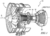
- the gas turbine engine 10 includes a fan 12, a compressor 14, a combustor 16 housing a plurality of nozzle guide vanes ("NGVs"), and a turbine 18 housing a plurality of stationary and rotating blades as shown in Fig. 1 .
- NVMs nozzle guide vanes
- Airfoils 20, as illustrated in the cutaway section of Fig. 2 may include any of the NGVs, stationary, and rotating blades in the gas turbine engine 10.
- airfoils 20 are shown to each include a sidewall 22, having pressure 24 and suction 26 surfaces, and a radially inner endwall 28 having contoured pressure 30 and suction 32 surfaces (sometimes called profiled endwalls).
- Contoured pressure and suction surfaces 30, 32 of endwall 28 are depicted as non-axisymmetric endwalls with complex three-dimensional sloped surfaces in x, r, and theta coordinates.
- Airfoils 20 may be formed of composite materials, such as ceramic matrix composites.
- airfoils 20 may include radially outer endwalls having non-axisymmetric endwalls with complex three-dimensional sloped surfaces in x, r, and theta coordinates, which may be the same or different form the radially inner endwall surface geometry.
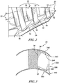
- FIG. 3 A schematic cross-sectional view of an airfoil 20 in accordance with the present disclosure is shown in Fig. 3 .
- Airfoil 20 is shown with multi-piece tooling 336 assembled on sidewall suction surface 26, radially inner endwall suction surface 32, and radially outer endwall suction surface 34.
- the multi-piece tooling 336 includes a suction side core tool 338, a suction side radially inner profiled endwall tool 340 and a suction side radially outer profiled endwall tool 342. As illustrated in Fig. 3 , a composite has already been applied via the multi-piece tooling 336 and the final airfoil 20 has a geometry has a complementary shape to the multi-piece tooling 336.
- Radially outer endwall suction surface 34 includes a recessed profile defining a three dimensional contour 344 that corresponds to a surface geometry 346 of the suction side radially outer profiled endwall tool 342.
- radially inner endwall suction surface 32 includes a recessed profile having a three dimensional contour 348 that corresponds to a surface geometry 350 of the suction side radially inner profiled endwall tool 340.
- Multi-piece tooling 336 permits suction side core tool 338 to be removed from the final composite airfoil 20, and subsequent removal of radially inner and outer profiled endwall tools 340, 342 from the formed three dimensional contours 344, 348.
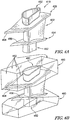
- Figs. 4A-4E illustrate how the multi-piece tooling 436 is assembled with a CMC preform 419 to form the airfoils of Figs. 1-3 .
- the multi-piece tooling 436 may be formed from graphite or alternative materials, such as molybdenum and is depicted transparently for ease of reference.
- the CMC preform 419 includes radially outer and inner preform endwalls 428, 454, a preform sidewall 422 extending between the preform endwalls 428 454, and distal preform tip ends 452 extending exterior to the preform endwalls 428, 454.
- Preform endwalls 428, 454 have non-contoured inner surfaces 456, 458.
- the inner surface 456, 458 may have stacks of ceramic fiber plys layered on the surfaces 456, 458 to form contoured protrusions that will be infiltrated to form rigid protrusions, such as the stacked formation of ceramic plies 855 sized and shaped progressively smaller to form the contours for an inner surface 856 shown in Fig. 8A .
- the distal end tools 460 may be coupled to the distal preform tip ends 452, with the distal preform tip ends 452 fitting into recesses in the distal end tools 460 as shown in Fig. 4B .
- the inner surfaces 456, 458 remain exposed and are not covered by the distal end tools 460.
- the distal end tools 460 provide flat exterior working surfaces 462 to secure, clamp, set down, and otherwise handle the CMC preform 419.
- the suction side multi-piece tooling 464 may be assembled and fitted between the distal end tools 460.
- the suction side multi-piece tooling 464 includes a suction side core tool 438, a suction side radially inner profiled endwall tool 440, and a suction side radially outer profiled endwall tool 442 as depicted in Fig. 4C .
- Each of the suction side core tool 438, suction side radially inner profiled endwall tool 440, and radially outer profiled endwall tool 442 may be positioned between the distal end tools 460 in any sequential order of assembly.
- Each of the suction side core tool 438, suction side radially inner profiled endwall tool 440, and radially outer profiled endwall tool 442 include a concavity 466 corresponding to the convex shape of the sidewall 22 of the CMC preform 419.
- the suction side core tool 438 is aligned with and adjacent to a larger area of the preform sidewall 422 relative to the radially inner and outer suction side profiled endwall tools 440, 442.
- the suction side core tool 438 is relatively thicker and larger than the radially inner and outer suction side profiled endwall tools 440, 442.
- the suction side radially inner and radially outer profiled endwall tools 440, 442 include three dimensional geometries 477 that define recesses on surfaces that face the inner surfaces 456, 458.
- the inner and radially outer profiled endwall tools 440, 442 contact with the inner surfaces 456, 458 and cause the inner surfaces 456, 458 to conform with and take on the three dimensional shape of the suction side radially inner and radially outer profiled endwall tools 440, 442.
- the suction side radially inner and radially outer profiled endwall tools 440, 442 include three dimensional geometries 477 on surfaces that face the inner surfaces 456, 458, to form voids between the inner surfaces 456, 458 and the suction side radially inner and radially outer profiled endwall tools 440, 442 so that a three dimensional surface geometry may be formed on the inner surfaces 456, 458.
- fiber plys on the inner surfaces 456, 458 are located in the voids so that the three dimensional surface geometry may be formed on the inner surfaces 456, 458 via the fiber plys.
- the three dimensional surface geometries 477 may be the same or different in the suction side radially inner and radially outer profiled endwall tools 440, 442.
- the pressure side multi-piece tooling 468 includes pressure side core tool 472, a pressure side radially inner profiled endwall tool 474 and a pressure side radially outer profiled endwall tool 476 as depicted in Fig. 4D .
- Each of the pressure side core tool 472, pressure side radially inner profiled endwall tool 474, and radially outer profiled endwall tool 476 may be positioned between the distal end tools 460 in any sequential order of assembly.
- Each of the pressure side core tool 472, pressure side radially inner profiled endwall tool 474, and radially outer profiled endwall tool 476 include a convexity 470 corresponding to the concave shape of the sidewall 22 of the CMC preform 419.
- the pressure side core tool 472 is aligned with and adjacent to a larger area of the preform sidewall 422 relative to the radially inner and outer pressure side profiled endwall tools 474, 476.
- the pressure side core tool 472 is relatively thicker and larger than the radially inner and outer pressure side profiled endwall tools 474, 476.
- the pressure side radially inner and outer pressure side profiled endwall tools 474, 476 include three dimensional geometries 477 that define recesses on surfaces that face the inner surfaces 456, 458.
- the inner and radially outer profiled endwall tools 474, 476 contact with the inner surfaces 456, 458 and cause the inner surfaces 456, 458 conform with and take on the three dimensional shape of the pressure side radially inner and radially outer profiled endwall tools 474, 476.
- the pressure side radially inner and radially outer profiled endwall tools 474, 476 may include three dimensional geometries 477 on surfaces that face the non-contoured inner surfaces 456, 458, to form voids between the non-contoured inner surfaces 456, 458 and the pressure side radially inner and radially outer profiled endwall tools 474, 476 so that a three dimensional surface geometry may be formed on the non-contoured inner surfaces 456, 458.
- fiber plys on the inner surfaces 456, 458 are located in the voids so that the three dimensional surface geometry may be formed on the inner surfaces 456, 458 via the fiber plys.
- inner surfaces 456, 458 may be deformed to fill the voids by a corresponding male tool of complementary shape of the radially inner profiled endwall tools 474, 476 positioned radially exterior to the endwall preforms deforming a stack of ceramic plies 855 as shown in Fig. 8B .
- the three dimensional surface geometries 477 may be the same or different in the suction side radially inner and radially outer profiled endwall tools 440, 442.
- the three dimensional surface geometries 477 may be the same or different in the pressure side radially inner and radially outer profiled endwall tools 474, 476 and may be the same or different than the three dimensional geometries 477 in the suction side radially inner and radially outer profiled endwall tools 440, 442.
- the multi-piece tooling 436 has complementary shapes to completely surround and cover the CMC preform 419 and fit between the distal end tools 460.
- the pressure and suction side core tools 438, 472 may be inserted last in order to hold the assembled multi-piece tooling 436 in a fitted position.
- tooling may be installed in a vertically stacking bottom-up sequence from the radially inner to radially outer endwall.
- the resulting assembled multi-piece tooling 436 with distal end tools 460 forms a rectangular box shape.
- the tools may be formed to fit together in other shapes as well.
- Multiple infiltration holes may be formed in the multi-piece tooling to introduce CMC or other composite materials in order to form the surfaces of the final CMC airfoil, as depicted for example in Fig. 3 with contoured radially inner and outer endwalls.
- the CMC may be liquefied and may be introduced, for example, by chemical vapor infilitration (CVI) or other methods.
- CVI chemical vapor infilitration
- the pressure side and suction side core tools 438, 472 must be removed first as the newly formed radially inner and outer endwall will have contours that fill the previously-existing voids, thereby blocking their removal.
- pressure and suction side core tools 438, 472 must be removed first in a radial direction to allow for clearance of the newly formed radially inner and outer endwall contours by vertical, or movement in a radial direction, of suction side radially inner and radially outer profiled endwall tools 440, 442 and of pressure side radially inner and outer profiled endwall tools 474, 476 when removing the multi-piece tooling 436.
- the multi-piece tooling 436 is illustrated in Fig.
- the multi-piece tooling may be designed to have only one, two, three or all four profiled endwall tools to profile one or more portions of the radially inner or radially outer endwall.
- the endwall tools that are not profiled may form a unitary singular tool structure with the corresponding core tool.
- the multi-piece tool may comprise a core and endwall tool as a unitary structure with a non profiled radially outer endwall and a separate radially inner profiled endwall tool, or vice versa, on one or both of the pressure or suction sides.
- the radially outer suction side profiled endwall tool 442 and the radially outer pressure side profiled endwall tool 476 each include concave three dimensional geometries 477 to form contours on the radially outer endwall surface. Respective convex 470 and concave 466 surfaces form an opening to accommodate the blade sidewall 22 therethrough. Otherwise, radially outer suction side profiled endwall tool 440 and radially outer pressure side profiled endwall tool 476 contact each other fully at their abutting surfaces. Radially inner suction side and pressure side profiled endwall tools are similarly formed with three dimensional geometries, convex and concave surfaces, and fully contacting abutting surfaces.
- airfoils 620 may be formed with protrusions 680 formed on the endwall surfaces.
- the airfoils 620 each include a sidewall 622, having pressure 624 and suction 626 surfaces and a radially inner endwall 628 having contoured pressure 630 and suction 632 surfaces. Contoured pressure and suction surfaces 630, 632 of endwall 628 are depicted as non-axisymmetric endwalls with three-dimensional protrusions 680 extending out from the endwall surfaces.
- the airfoils 620 may be formed of composite materials, such as ceramic matrix composites.
- the airfoils 620 may include radially outer endwalls having non-axisymmetric endwalls with three-dimensional protrusions, which may be the same or different form the radially inner endwall surface geometry. These protrusions may be pyramidal as depicted, cylindrical, cubical, or any other geometry sharply defined edges.
- FIG. 7 A method of forming endwall surfaces with protrusions is shown in Fig. 7 may be performed by impregnating a porous vane preform with slurry 702, protrusions may be formed in the endwalls 704, by a stamping a cast into a slurry deposited on the endwall or a molding the slurry between the endwall and a cast, drying the slurry 706, and infiltrating the dried vane preform including the one or more protrusions with a molten infiltrant to form the composite endwall of the airfoil 708.
- An exemplary view of a slurry-formed inner endwall contour 880 formed on a surface of a stack of ceramic plies 855 is illustrated in Fig. 8C . Further details of stamping and casting processes may be found in United States patent application US 2016/0214907 A1 entitled FORMING A SURFACE LAYER OF A CERAMIC MATRIX COMPOSITE ARTICLE.
- the disclosed embodiments minimize the number of tool pieces in the multi-piece tooling so that the size of each individual tool may be maximized. Maximized size may prolong each tools life and limit breakages. By making the tools of the multi-piece tooling from graphite or molybdenum, the tools may not distort or lose dimensional conformance like some metallic tools do overtime.
- the present disclosure offers the ability to manufacture profiled endwalls in CMC components.
- Profiled end walls may limit the vorticity generated along high turning, high Mach number airfoils, which may be a source of significant efficiency deficit. As such, the present disclosure may provide for a significant engine fuel burn benefit.
- profiled endwalls (PEWs) of the present disclosure include the application of streamline curvature to endwalls in a turbine. This results in non-axisymmetric endwalls which are complex 3D surfaces in x,r and theta.
- the pressure gradient between the pressure surface of one aerofoil and the suction surface of the adjacent aerofoil over turbine endwalls may result in an overturning of low momentum fluid in the endwall boundary layer. This overtuning of flow may increase the secondary loss.
- Profiled endwalls of the present disclose may use the local surface curvature of the endwalls to change the local static pressure field. This may reduce the overturning of flow and secondary loss.
- the multi-piece tooling of the present disclosure enables formation of these profiled features in CMC parts.
- a central tool could still be withdrawn.
- the size of the endwall tool may be dictated by the strength of the tool material (i.e. if graphite then a relatively thick tool may be used for durability).
- Alternative materials such as molybdenum could be used. Illustrations of the embodiments shown in the drawings are not show with CVI gas infiltration holes or tool restraints for clarity purposes.
- Figs. 4A-4E illustrate an embodiment of the profiled endwall tool.
- the tool split lines are indicative and would be located as per one or more of the following considerations: minimizing the number of tool pieces used by locating in such a way that the size of each individual tool can be maximized (while accepting that the tool cannot encompass the entire aerofoil); maximizing the size of each individual tool to prolong tool life and reduce breakages (CMC CVI tools may be made from graphite which may be prone to breaking.
- CMC pre-form tools may be metallic and breaking is less of a concern but distortion and dimensional conformance is); maximizing the number of CVI gas infiltration holes and penetration to the CMC surfaces; ease of assembling the tools around the CMC pre-form; and ease of locating/restraining tools relative to each other for CMC part dimensional conformance.
Landscapes
- Engineering & Computer Science (AREA)
- Chemical & Material Sciences (AREA)
- Materials Engineering (AREA)
- Mechanical Engineering (AREA)
- General Engineering & Computer Science (AREA)
- Ceramic Engineering (AREA)
- Manufacturing & Machinery (AREA)
- Composite Materials (AREA)
- Structural Engineering (AREA)
- Organic Chemistry (AREA)
- Chemical Kinetics & Catalysis (AREA)
- Physics & Mathematics (AREA)
- Fluid Mechanics (AREA)
- Inorganic Chemistry (AREA)
- Turbine Rotor Nozzle Sealing (AREA)
- Structures Of Non-Positive Displacement Pumps (AREA)
Abstract
Description
- The present disclosure relates generally to gas turbine engines, and more specifically to manufacturing profiled endwalls in ceramic matrix composite ("CMC") components in gas turbine engines.
- Gas turbine engines are used to power aircraft, watercraft, power generators, and the like. Gas turbine engines typically include a compressor, a combustor, and a turbine. The compressor compresses air drawn into the engine and delivers high pressure air to the combustor. In the combustor, fuel is mixed with the high pressure air and is ignited. Products of the combustion reaction in the combustor are directed into the turbine where work is extracted to drive the compressor and, sometimes, an output shaft. Left-over products of the combustion are exhausted out of the turbine and may provide thrust in some applications.
- To withstand heat from the combustion products received from the combustor, the turbine may include turbine wheels having blades that comprise composite materials adapted to interact with the hot combustion products. In turbine endwalls, the pressure gradient between the pressure surface of one airfoil and the suction surface of an adjacent airfoil results in overturning of low momentum fluid in the endwall boundary layer, which increases secondary loss. Profiled endwalls may use local surface curvature to change local static pressure field. This results in reducing overturning of flow and secondary loss and significant engine fuel burn benefit. However, manufacturing of profiled endwalls in CMC components can present design challenges.
- The present disclosure provides a method of forming a ceramic matrix composite as set out in the appended claims.
- The present disclosure may comprise one or more of the following features and combinations thereof.
- A method of forming a ceramic matrix composite vane with profiled endwalls in accordance with the present disclosure includes a number of steps. The method may comprise providing a vane preform having an inner endwall preform, an outer endwall preform spaced apart radially from the inner endwall preform relative to an axis, and an airfoil preform that extends radially between and interconnects the inner endwall preform and the outer endwall preform, and providing a multi-piece tool that includes an inner endwall tool, an outer endwall tool, and a core tool. The inner endwall tool may be formed to define a first recessed profile that extends radially outward into the inner endwall tool. The outer endwall tool may be formed to define a second recessed profile that extends radially inward into the outer endwall tool.
- The inner endwall tool may be located adjacent the inner endwall preform and the outer endwall tool adjacent the outer endwall preform. The core tool may be inserted radially between the inner endwall tool and the outer endwall tool such that the core tool is adjacent the airfoil preform and holds the inner endwall tool and the outer endwall tool in position radially relative to the vane preform. The vane preform tool may be infilatrated with ceramic materials to provide a ceramic matrix composite vane, the ceramic matrix composite vane including a ceramic matrix composite inner endwall having a first contour corresponding with the first recessed profile, a ceramic matrix composite outer endwall having a contour corresponding with the second recessed profile, and a ceramic matrix composite airfoil that extends between and interconnects the ceramic matrix composite inner endwall and the ceramic matrix composite outer endwall.
- In some embodiments, the method may further comprise moving the core tool away from the ceramic matrix composite vane, the inner endwall tool, and the outer endwall tool after the infiltrating step. The method may include separating the inner endwall tool from the ceramic matrix composite inner endwall after the step of moving the core tool and separating the outer endwall tool from the ceramic matrix composite outer endwall after the step of moving the core tool.
- In some embodiments, the method may further comprise blocking the inner endwall tool from moving relative to the ceramic matrix composite vane with the first contour of the ceramic matrix composite inner endwall before the step of moving the core tool away from the ceramic matrix composite vane.
- In some embodiments, the method may further comprise blocking the outer endwall tool from moving relative to the ceramic matrix composite vane with the second contour of the ceramic matrix composite outer endwall before the step of moving the core tool away from the ceramic matrix composite vane.
- In some embodiments, separating the inner endwall tool from the ceramic matrix composite inner endwall may include moving the inner endwall tool radially outward relative to the ceramic matrix composite vane. In some embodiments, separating the outer endwall tool from the ceramic matrix composite outer endwall may include moving the outer endwall tool radially inward relative to the ceramic matrix composite vane.
- In some embodiments, the method may comprise blocking the inner endwall tool from moving axially and circumferentially relative to the ceramic matrix composite vane with the first contour of the ceramic matrix composite inner endwall. In some embodiments, the step of inserting the core tool may include translating the core tool relative to the inner endwall tool and the outer endwall tool.
- In some embodiments, the inner endwall preform may include a body connected with the airfoil and a thickened portion supported by the body and spaced apart from the airfoil preform. The thickened portion may extend into the first recessed profile of the inner endwall tool when the inner endwall tool is located adjacent the inner endwall preform.
- According to an aspect of the present disclosure, a method of manufacturing profiled endwalls on ceramic matrix composite (CMC) airfoils may comprise a number of steps. The method may include providing an airfoil preform including a radially inner endwall, a radially outer endwall spaced apart radially from the radially inner endwall relative to an axis, and an airfoil body that extends radially between the radially inner endwall and the radially outer endwall, providing tool means for forming a three-dimensional contour in a surface of the endwall, and forming a CMC airfoil having a profiled endwall including the three-dimensional contour in a surface of the endwall.
- In some embodiments, the tool means may comprise at least a core tool for forming a blade sidewall of the airfoil, and radially inner and outer profiled endwall tools. At least one of the radially inner or radially outer profiled endwall tools may include a surface geometry for forming the three-dimensional contour in the surface of the endwall.
- In some embodiments, the tool means comprises a multi-piece tool including suction side radially inner and outer profiled endwall tools, a suction side core tool, pressure side radially inner and outer profiled endwall tools, and a pressure side core tool. Forming the CMC airfoil may further comprise assembling the multi-piece tool around the preform so that each respective suction side tool contacts and aligns with the respective pressure side tool.
- In some embodiments, the method may further comprise removing the multi-piece tool from the formed CMC airfoil having a profiled endwall. The suction side and pressure side core tools may be removed prior to removal of the suction side and pressure side endwall tools.
- In some embodiments, the tool means may comprise a cast including one or more recesses to form one or more protrusions on the radially inner or outer endwall of the CMC airfoil. In some embodiments, the forming step may include locating the preform in the cast so that the one or more recesses form a negative space between an endwall surface of the preform and the cast surface, and impregnating the porous preform with a slurry to fill the negative space and form projections on the endwall.
- In some embodiments, a slurry is deposited on a surface of the endwall. The cast may be stamped into the slurry so that the profiled endwall includes one or more protrusions.
- According to the present disclosure, a method of manufacturing profiled endwalls in ceramic matrix composite (CMC) airfoils may comprise a number of steps. The method may include providing an airfoil preform including a radially inner endwall and a radially outer endwall, locating tooling at endwall surfaces of the radially inner and outer endwalls, the tooling including geometric voids corresponding to a three-dimensional surface contour to be formed on the endwall surfaces, and providing a material to the endwall surfaces to fill the geometric voids and form the three-dimensional surface contour profile on the endwalls
- In some embodiments, the tooling may comprise radially inner and outer profiled endwall tools and a core tool to be positioned between the radially inner and outer profiled endwall tools. In some embodiments, the tooling may comprise a cast and the profiled endwall includes protrusions. The protrusions may be formed by one of infiltration or stamping.
- In some embodiments, the core tool may be configured to extend along a pressure or suction side of a vane wall. The radially inner and outer profiled endwall tools may further comprise suction side and pressure side radially inner and outer profile endwall tools. The core tool may comprise suction side and pressure side core tools. Each of the suction side and corresponding pressure side tools may be complementary in shape in order to surround the preform.
- These and other features of the present disclosure will become more apparent from the following description of the illustrative embodiments.
-
-
Fig. 1 is a partial cutaway view of a gas turbine engine that includes a fan, a compressor, a combustor, and a turbine that includes a plurality of turbine wheel assemblies in accordance with the present disclosure that are adapted to extract work from hot combustion products received from the combustor; -
Fig. 2 is a perspective cutaway view of a portion of one of the turbine wheel assemblies included in the gas turbine engine ofFig. 1 showing that the turbine wheel assembly includes a plurality of composite blades and that a radially inner endwall of each of the blades has three-dimensional sloped contouring along its surface to provide a profiled endwall; -
Fig. 3 is a diagrammatic view of components of a multi-piece tooling that forms the three-dimensional contoured surface on radially inner and radially outer endwalls of the composite blade, the multi-piece tool including a core tool, a radially inner endwall profiled endwall tool, and a radially outer profiled endwall tool; -
Fig. 4A is a perspective view of an airfoil CMC preform used to manufacture the turbine wheel assembly ofFig. 2 , the airfoil CMC preform having preform radially inner and outer endwalls, a preform blade sidewall, and preform distal ends; -
Fig. 4B is a perspective view of the CMC preform ofFig. 4A in which distal end tools, shown as being transparent for ease of reference, have been coupled to the preform to secure the preform and leave exposed surfaces of the radially inner and outer endwalls and the blade sidewall; -
Fig. 4C is a perspective view of the CMC preform ofFig. 4B in which suction side tooling, shown as being transparent for ease of reference, of the multi-piece tooling is applied to a suction side of the CMC preform; -
Fig.4D is a perspective view of the CMC preform ofFig. 4C in which pressure side tooling, shown as being transparent for ease of reference, of the multi-piece tooling is applied to a pressure side of the CMC preform; -
Fig. 4E is an exterior view of the fully assembled multi-piece tooling encasing the CMC preform ofFig. 4A , depicting the distal end tools and suction and pressure side tools of the multi-piece tooling; -
Fig. 5 illustrates exemplary radially outer suction side and pressure side profiled endwall tools; -
Fig. 6 is a perspective cutaway view of a portion of one of the turbine wheel assemblies included in the gas turbine engine ofFig. 1 showing that the turbine wheel assembly includes a plurality of composite blades, and a radially inner endwall of each of the blades has three-dimensional protrusions along its surface; -
Fig. 7 is a diagram of a method of forming the airfoil blades ofFig. 6 having three-dimensional protrusions on the endwalls; and -
Fig. 8A-8C illustrate three different cross-sectional views of configurations of inner endwalls formed contoured by layered plies including layered plies of different dimensions, a deformed plurality of layered plies, and a plurality of plies with a slurry formation formed on the radially inner surface. - For the purposes of promoting an understanding of the principles of the disclosure, reference will now be made to a number of illustrative embodiments illustrated in the drawings and specific language will be used to describe the same.
-
Airfoils 20 for use in a gas turbine engine are shown inFig. 2 . Thegas turbine engine 10 includes afan 12, acompressor 14, acombustor 16 housing a plurality of nozzle guide vanes ("NGVs"), and aturbine 18 housing a plurality of stationary and rotating blades as shown inFig. 1 . -
Airfoils 20, as illustrated in the cutaway section ofFig. 2 , may include any of the NGVs, stationary, and rotating blades in thegas turbine engine 10. For illustrative purposes,airfoils 20 are shown to each include asidewall 22, havingpressure 24 andsuction 26 surfaces, and a radiallyinner endwall 28 having contouredpressure 30 andsuction 32 surfaces (sometimes called profiled endwalls). Contoured pressure and suction surfaces 30, 32 ofendwall 28 are depicted as non-axisymmetric endwalls with complex three-dimensional sloped surfaces in x, r, and theta coordinates.Airfoils 20 may be formed of composite materials, such as ceramic matrix composites. Although not depicted,airfoils 20 may include radially outer endwalls having non-axisymmetric endwalls with complex three-dimensional sloped surfaces in x, r, and theta coordinates, which may be the same or different form the radially inner endwall surface geometry. - A schematic cross-sectional view of an
airfoil 20 in accordance with the present disclosure is shown inFig. 3 .Airfoil 20 is shown withmulti-piece tooling 336 assembled onsidewall suction surface 26, radially innerendwall suction surface 32, and radially outerendwall suction surface 34. - The
multi-piece tooling 336 includes a suctionside core tool 338, a suction side radially inner profiledendwall tool 340 and a suction side radially outer profiledendwall tool 342. As illustrated inFig. 3 , a composite has already been applied via themulti-piece tooling 336 and thefinal airfoil 20 has a geometry has a complementary shape to themulti-piece tooling 336. - Radially outer
endwall suction surface 34 includes a recessed profile defining a threedimensional contour 344 that corresponds to asurface geometry 346 of the suction side radially outer profiledendwall tool 342. Likewise, radially innerendwall suction surface 32 includes a recessed profile having a threedimensional contour 348 that corresponds to asurface geometry 350 of the suction side radially inner profiledendwall tool 340.Multi-piece tooling 336 permits suctionside core tool 338 to be removed from the finalcomposite airfoil 20, and subsequent removal of radially inner and outer profiledendwall tools dimensional contours -
Figs. 4A-4E illustrate how themulti-piece tooling 436 is assembled with aCMC preform 419 to form the airfoils ofFigs. 1-3 . Themulti-piece tooling 436 may be formed from graphite or alternative materials, such as molybdenum and is depicted transparently for ease of reference. As shown inFig. 4A , theCMC preform 419 includes radially outer and inner preform endwalls 428, 454, apreform sidewall 422 extending between the preform endwalls 428 454, and distal preform tip ends 452 extending exterior to the preform endwalls 428, 454.Preform endwalls inner surfaces inner surface surfaces ceramic plies 855 sized and shaped progressively smaller to form the contours for an inner surface 856 shown inFig. 8A . - The
distal end tools 460 may be coupled to the distal preform tip ends 452, with the distal preform tip ends 452 fitting into recesses in thedistal end tools 460 as shown inFig. 4B . Theinner surfaces distal end tools 460. Thedistal end tools 460 provide flatexterior working surfaces 462 to secure, clamp, set down, and otherwise handle theCMC preform 419. The suctionside multi-piece tooling 464 may be assembled and fitted between thedistal end tools 460. - The suction
side multi-piece tooling 464 includes a suctionside core tool 438, a suction side radially inner profiledendwall tool 440, and a suction side radially outer profiledendwall tool 442 as depicted inFig. 4C . Each of the suctionside core tool 438, suction side radially inner profiledendwall tool 440, and radially outer profiledendwall tool 442 may be positioned between thedistal end tools 460 in any sequential order of assembly. Each of the suctionside core tool 438, suction side radially inner profiledendwall tool 440, and radially outer profiledendwall tool 442 include aconcavity 466 corresponding to the convex shape of thesidewall 22 of theCMC preform 419. - The suction
side core tool 438 is aligned with and adjacent to a larger area of thepreform sidewall 422 relative to the radially inner and outer suction side profiledendwall tools side core tool 438 is relatively thicker and larger than the radially inner and outer suction side profiledendwall tools endwall tools dimensional geometries 477 that define recesses on surfaces that face theinner surfaces endwall tools inner surfaces inner surfaces endwall tools - In some embodiments, the suction side radially inner and radially outer profiled
endwall tools dimensional geometries 477 on surfaces that face theinner surfaces inner surfaces endwall tools inner surfaces inner surfaces inner surfaces dimensional surface geometries 477 may be the same or different in the suction side radially inner and radially outer profiledendwall tools - The pressure
side multi-piece tooling 468 includes pressureside core tool 472, a pressure side radially inner profiledendwall tool 474 and a pressure side radially outer profiledendwall tool 476 as depicted inFig. 4D . Each of the pressureside core tool 472, pressure side radially inner profiledendwall tool 474, and radially outer profiledendwall tool 476 may be positioned between thedistal end tools 460 in any sequential order of assembly. Each of the pressureside core tool 472, pressure side radially inner profiledendwall tool 474, and radially outer profiledendwall tool 476 include aconvexity 470 corresponding to the concave shape of thesidewall 22 of theCMC preform 419. - The pressure
side core tool 472 is aligned with and adjacent to a larger area of thepreform sidewall 422 relative to the radially inner and outer pressure side profiledendwall tools side core tool 472 is relatively thicker and larger than the radially inner and outer pressure side profiledendwall tools - Illustratively, the pressure side radially inner and outer pressure side profiled
endwall tools dimensional geometries 477 that define recesses on surfaces that face theinner surfaces endwall tools inner surfaces inner surfaces endwall tools - In some embodiments, the pressure side radially inner and radially outer profiled
endwall tools dimensional geometries 477 on surfaces that face the non-contouredinner surfaces inner surfaces endwall tools inner surfaces inner surfaces inner surfaces inner surfaces endwall tools ceramic plies 855 as shown inFig. 8B . - The three
dimensional surface geometries 477 may be the same or different in the suction side radially inner and radially outer profiledendwall tools dimensional surface geometries 477 may be the same or different in the pressure side radially inner and radially outer profiledendwall tools dimensional geometries 477 in the suction side radially inner and radially outer profiledendwall tools - As illustrated in
Fig. 4E , themulti-piece tooling 436 has complementary shapes to completely surround and cover theCMC preform 419 and fit between thedistal end tools 460. The pressure and suctionside core tools multi-piece tooling 436 in a fitted position. Alternatively, tooling may be installed in a vertically stacking bottom-up sequence from the radially inner to radially outer endwall. The resulting assembledmulti-piece tooling 436 withdistal end tools 460 forms a rectangular box shape. However, the tools may be formed to fit together in other shapes as well. - Multiple infiltration holes (not shown) may be formed in the multi-piece tooling to introduce CMC or other composite materials in order to form the surfaces of the final CMC airfoil, as depicted for example in
Fig. 3 with contoured radially inner and outer endwalls. The CMC may be liquefied and may be introduced, for example, by chemical vapor infilitration (CVI) or other methods. The pressure side and suctionside core tools side core tools endwall tools endwall tools multi-piece tooling 436. Although themulti-piece tooling 436 is illustrated inFig. 4A-4E has having both radially inner and radially outer profiledendwall tools - As seen in
Fig. 5 , the radially outer suction side profiledendwall tool 442 and the radially outer pressure side profiledendwall tool 476 each include concave threedimensional geometries 477 to form contours on the radially outer endwall surface. Respective convex 470 and concave 466 surfaces form an opening to accommodate theblade sidewall 22 therethrough. Otherwise, radially outer suction side profiledendwall tool 440 and radially outer pressure side profiledendwall tool 476 contact each other fully at their abutting surfaces. Radially inner suction side and pressure side profiled endwall tools are similarly formed with three dimensional geometries, convex and concave surfaces, and fully contacting abutting surfaces. - According to another embodiment in
Fig. 6 ,airfoils 620 may be formed withprotrusions 680 formed on the endwall surfaces. Theairfoils 620 each include asidewall 622, havingpressure 624 and suction 626 surfaces and a radially inner endwall 628 having contoured pressure 630 and suction 632 surfaces. Contoured pressure and suction surfaces 630, 632 of endwall 628 are depicted as non-axisymmetric endwalls with three-dimensional protrusions 680 extending out from the endwall surfaces. Theairfoils 620 may be formed of composite materials, such as ceramic matrix composites. Although not depicted, theairfoils 620 may include radially outer endwalls having non-axisymmetric endwalls with three-dimensional protrusions, which may be the same or different form the radially inner endwall surface geometry. These protrusions may be pyramidal as depicted, cylindrical, cubical, or any other geometry sharply defined edges. - A method of forming endwall surfaces with protrusions is shown in
Fig. 7 may be performed by impregnating a porous vane preform withslurry 702, protrusions may be formed in theendwalls 704, by a stamping a cast into a slurry deposited on the endwall or a molding the slurry between the endwall and a cast, drying theslurry 706, and infiltrating the dried vane preform including the one or more protrusions with a molten infiltrant to form the composite endwall of theairfoil 708. An exemplary view of a slurry-formedinner endwall contour 880 formed on a surface of a stack ofceramic plies 855 is illustrated inFig. 8C . Further details of stamping and casting processes may be found in United States patent applicationUS 2016/0214907 A1 entitled FORMING A SURFACE LAYER OF A CERAMIC MATRIX COMPOSITE ARTICLE. - The disclosed embodiments minimize the number of tool pieces in the multi-piece tooling so that the size of each individual tool may be maximized. Maximized size may prolong each tools life and limit breakages. By making the tools of the multi-piece tooling from graphite or molybdenum, the tools may not distort or lose dimensional conformance like some metallic tools do overtime.
- The present disclosure offers the ability to manufacture profiled endwalls in CMC components. Profiled end walls may limit the vorticity generated along high turning, high Mach number airfoils, which may be a source of significant efficiency deficit. As such, the present disclosure may provide for a significant engine fuel burn benefit.
- Generally, profiled endwalls (PEWs) of the present disclosure include the application of streamline curvature to endwalls in a turbine. This results in non-axisymmetric endwalls which are complex 3D surfaces in x,r and theta. The pressure gradient between the pressure surface of one aerofoil and the suction surface of the adjacent aerofoil over turbine endwalls may result in an overturning of low momentum fluid in the endwall boundary layer. This overtuning of flow may increase the secondary loss. Profiled endwalls of the present disclose may use the local surface curvature of the endwalls to change the local static pressure field. This may reduce the overturning of flow and secondary loss.
- The multi-piece tooling of the present disclosure enables formation of these profiled features in CMC parts. By applying profiled tooling with limited thickness at the endwall region, a central tool could still be withdrawn. The size of the endwall tool may be dictated by the strength of the tool material (i.e. if graphite then a relatively thick tool may be used for durability). Alternative materials such as molybdenum could be used. Illustrations of the embodiments shown in the drawings are not show with CVI gas infiltration holes or tool restraints for clarity purposes.
-
Figs. 4A-4E illustrate an embodiment of the profiled endwall tool. The tool split lines are indicative and would be located as per one or more of the following considerations: minimizing the number of tool pieces used by locating in such a way that the size of each individual tool can be maximized (while accepting that the tool cannot encompass the entire aerofoil); maximizing the size of each individual tool to prolong tool life and reduce breakages (CMC CVI tools may be made from graphite which may be prone to breaking. CMC pre-form tools may be metallic and breaking is less of a concern but distortion and dimensional conformance is); maximizing the number of CVI gas infiltration holes and penetration to the CMC surfaces; ease of assembling the tools around the CMC pre-form; and ease of locating/restraining tools relative to each other for CMC part dimensional conformance. - While the disclosure has been illustrated and described in detail in the foregoing drawings and description, the same is to be considered as exemplary and not restrictive in character, it being understood that only illustrative embodiments thereof have been shown and described and that all changes and modifications that come within the scope of the following claims are desired to be protected.
- The following numbered clauses include embodiments that are contemplated and non-limiting:
- Clause 1. A method of forming a ceramic matrix composite vane with profiled endwalls, the method comprising the steps of:
- providing a vane preform having an inner endwall preform, an outer endwall preform spaced apart radially from the inner endwall preform relative to an axis, and an airfoil preform that extends radially between and interconnects the inner endwall preform and the outer endwall preform;
- providing a multi-piece tool that includes an endwall tool, and a core tool, the endwall tool formed to define a first recessed profile that extends radially into the endwall tool;
- locating the endwall tool adjacent one of the inner endwall preform and the outer endwall preform;
- inserting the core tool radially between the inner endwall preform and the outer endwall preform such that the core tool is adjacent the airfoil preform and holds the endwall tool in position radially relative to the vane preform; and
- infiltrating the vane preform with ceramic materials to provide the ceramic matrix composite vane, the ceramic matrix composite vane including a ceramic matrix composite inner endwall or outer endwall having a first contour corresponding with the first recessed profile, and a ceramic matrix composite airfoil that extends between and interconnects the ceramic matrix composite inner endwall and the ceramic matrix composite outer endwall.
- Clause 2. The method of clause 1, wherein endwall tool comprises an inner endwall tool and the inner endwall has the first controur, and the multi-piece tool further comprises an outer endwall tool, and the vane preform further comprises an outerend wall having a contour corresponding with the second recessed profile, the method further comprising moving the core tool away from the ceramic matrix composite vane, the inner endwall tool, and the outer endwall tool after the infiltrating step, separating the inner endwall tool from the ceramic matrix composite inner endwall after the step of moving the core tool, and separating the outer endwall tool from the ceramic matrix composite outer endwall after the step of moving the core tool.
- Clause 3. The method of clause 2, further comprising blocking the inner endwall tool from moving relative to the ceramic matrix composite vane with the first contour of the ceramic matrix composite inner endwall before the step of moving the core tool away from the ceramic matrix composite vane.
- Clause 4. The method of clause 2, further comprising blocking the outer endwall tool from moving relative to the ceramic matrix composite vane with the second contour of the ceramic matrix composite outer endwall before the step of moving the core tool away from the ceramic matrix composite vane.
- Clause 5. The method of clause 2, wherein separating the inner endwall tool from the ceramic matrix composite inner endwall includes moving the inner endwall tool radially outward relative to the ceramic matrix composite vane, and.
- Clause 6. The method of clause 2, wherein separating the outer endwall tool from the ceramic matrix composite outer endwall includes moving the outer endwall tool radially inward relative to the ceramic matrix composite vane.
- Clause 7. The method of clause 1, further comprising blocking the endwall tool from moving axially and circumferentially relative to the ceramic matrix composite vane with the first contour of the ceramic matrix composite inner endwall.
- Clause 8. The method of clause 1, wherein the step of inserting the core tool includes translating the core tool relative to the endwall tool.
- Clause 9. The method of clause 1, wherein the inner endwall preform includes a body connected with the airfoil and a thickened portion supported by the body and spaced apart from the airfoil preform and the thickened portion extends into the first recessed profile of the endwall tool when the endwall tool is located adjacent the inner endwall preform.
-
Clause 10. A method of manufacturing profiled endwalls on ceramic matrix composite (CMC) airfoils, the method comprising:- providing an airfoil preform including a radially inner endwall, a radially outer endwall spaced apart radially from the radially inner endwall relative to an axis, and an airfoil body that extends radially between the radially inner endwall and the radially outer endwall,
- providing tool means for forming a three-dimensional contour in a surface of the endwall, and
- forming a CMC airfoil having a profiled endwall including the three-dimensional contour in a surface of the endwall.
- Clause 11. The method of
clause 10, wherein the multi-piece tool comprises at least a core tool for forming a blade sidewall of the airfoil, and radially inner and outer profiled endwall tools, wherein at least one of the radially inner or radially outer profiled endwall tools includes a surface geometry for forming the three-dimensional contour in the surface of the endwall. -
Clause 12. The method ofclause 10, wherein the tool means comprises a multi-piece tool including suction side radially inner and outer profiled endwall tools, a suction side core tool, pressure side radially inner and outer profiled endwall tools, and a pressure side core tool, and
wherein forming the CMC airfoil further comprises assembling the multi-piece tool around the preform so that each respective suction side tool contacts and aligns with the respective pressure side tool. - Clause 13. The method of
clause 12, further comprising removing the multi-piece tool from the formed CMC airfoil having a profiled endwall, wherein suction side and pressure side core tools are removed prior to removal of the suction side and pressure side endwall tools. -
Clause 14. The method ofclause 10, wherein the tool means comprises a cast including one or more recesses to form one or more protrusions on the radially inner or outer endwall of the CMC airfoil. - Clause 15. The method of
clause 10, wherein the forming includes locating the preform in a cast so that the one or more recesses form a negative space between an endwall surface of the preform and the cast surface, and impregnating the porous preform with a slurry to fill the negative space and form projections on the endwall. -
Clause 16. The method of clause 15, wherein a slurry is deposited on a surface of the endwall and the cast is stamped into the slurry so that the profiled endwall includes one or more protrusions. - Clause 17. A method of manufacturing profiled endwalls in ceramic matrix composite (CMC) airfoils comprising:
- providing an airfoil preform including a radially inner endwall and a radially outer endwall,
- locating tooling at endwall surfaces of the radially inner and radially outer endwalls, the tooling including geometric voids corresponding to a three-dimensional surface contour to be formed on the endwall surfaces, and
- providing a material to the endwall surfaces to fill the geometric voids and form the three-dimensional surface contour profile on the endwalls.
-
Clause 18. The method of clause 17, wherein the tooling comprises radially inner and outer profiled endwall tools and a core tool to be positioned between the radially inner and outer profiled endwall tools. - Clause 19. The method of
clause 18, wherein the core tool is configured to extend along a pressure or suction side of a vane wall, and
wherein the radially inner and outer profiled endwall tools further comprise suction side and pressure side radially inner and outer profile endwall tools and the core tool comprises suction side and pressure side core tools, wherein each of the suction side and corresponding pressure side tools are complementary in shape in order to surround the preform. -
Clause 20. The method of clause 17, wherein the tooling comprises a cast and the profiled endwall includes protrusions, and wherein the protrusions are formed by one of infiltration or stamping.
Claims (15)
- A method of forming a ceramic matrix composite vane (20) with profiled endwalls, the method comprising the steps of:providing a vane preform (419) having an inner endwall preform (454), an outer endwall preform (428) spaced apart radially from the inner endwall preform relative to an axis, and an airfoil preform that extends radially between and interconnects the inner endwall preform and the outer endwall preform;providing a multi-piece tool (336, 464) that includes an endwall tool (340, 342), and a core tool (338), the endwall tool formed to define a first recessed profile that extends radially into the endwall tool;locating the endwall tool (340, 342) adjacent one of the inner endwall preform and the outer endwall preform;inserting the core tool (338) radially between the inner endwall preform (454) and the outer endwall preform (428) such that the core tool is adjacent the airfoil preform and holds the endwall tool in position radially relative to the vane preform; andinfiltrating the vane preform (419) with ceramic materials to provide the ceramic matrix composite vane, the ceramic matrix composite vane including a ceramic matrix composite inner endwall or outer endwall having a first contour corresponding with the first recessed profile, and a ceramic matrix composite airfoil that extends between and interconnects the ceramic matrix composite inner endwall and the ceramic matrix composite outer endwall.
- The method of claim 1, wherein endwall tool (340, 342) comprises an inner endwall tool and the inner endwall has the first controur, and the multi-piece tool further comprises an outer endwall tool, and the vane preform further comprises an outerend wall having a contour corresponding with the second recessed profile, the method further comprising moving the core tool (338) away from the ceramic matrix composite vane (20), the inner endwall tool, and the outer endwall tool after the infiltrating step, separating the inner endwall tool from the ceramic matrix composite inner endwall after the step of moving the core tool, and separating the outer endwall tool from the ceramic matrix composite outer endwall after the step of moving the core tool (338).
- The method of claim 1 or 2, further comprising blocking the inner endwall tool from moving relative to the ceramic matrix composite vane (20) with the first contour of the ceramic matrix composite inner endwall before the step of moving the core tool (338) away from the ceramic matrix composite vane (20).
- The method of any preceding claim, further comprising blocking the outer endwall tool from moving relative to the ceramic matrix composite vane with the second contour of the ceramic matrix composite outer endwall before the step of moving the core tool (338) away from the ceramic matrix composite vane (20).
- The method of any one of claims 2 to 4, wherein separating the inner endwall tool from the ceramic matrix composite inner endwall includes moving the inner endwall tool radially outward relative to the ceramic matrix composite vane (20).
- The method of any one of claims 2 to 5, wherein separating the outer endwall tool from the ceramic matrix composite outer endwall includes moving the outer endwall tool radially inward relative to the ceramic matrix composite vane (20).
- The method of any preceding claim, further comprising blocking the endwall tool from moving axially and circumferentially relative to the ceramic matrix composite vane with the first contour of the ceramic matrix composite inner endwall.
- The method of any preceding claim, wherein the step of inserting the core tool (338) includes translating the core tool relative to the endwall tool.
- The method of any preceding claim, wherein the inner endwall preform includes a body connected with the airfoil (20) and a thickened portion supported by the body and spaced apart from the airfoil preform and the thickened portion extends into the first recessed profile of the endwall tool when the endwall tool is located adjacent the inner endwall preform.
- A method of manufacturing profiled endwalls on ceramic matrix composite (CMC) airfoils (20), the method comprising the steps of:providing an airfoil preform including a radially inner endwall, a radially outer endwall spaced apart radially from the radially inner endwall relative to an axis, and an airfoil body that extends radially between the radially inner endwall and the radially outer endwall;providing tool means for forming a three-dimensional contour (348) in a surface of the endwall; andforming a CMC airfoil having a profiled endwall including the three-dimensional contour in a surface of the endwall.
- The method of claim 10, wherein the tool means comprises at least a core tool (338) for forming a blade sidewall of the airfoil, and radially inner and outer profiled endwall tools (340, 342), wherein at least one of the radially inner or radially outer profiled endwall tools includes a surface geometry (346, 477) for forming the three-dimensional contour (348) in the surface (32, 34) of the endwall.
- The method of claim 10 or 11, wherein the tool means comprises a multi-piece tool (336) including suction side radially inner and outer profiled endwall tools (340, 342), a suction side core tool (338), pressure side radially inner and outer profiled endwall tools (474, 476), and a pressure side core tool (472), and
wherein forming the CMC airfoil (20) further comprises assembling the multi-piece tool (336) around the preform so that each respective suction side tool contacts and aligns with the respective pressure side tool. - The method of any one of claims 10 to 12, further comprising removing the multi-piece tool (336) from the formed CMC airfoil (20) having a profiled endwall, wherein suction side and pressure side core tools (338, 472) are removed prior to removal of the suction side and pressure side endwall tools.
- The method of any one of claims 10 to 13, wherein the tool means comprises a cast including one or more recesses to form one or more protrusions on the radially inner (28) or outer endwall of the CMC airfoil (20).
- The method of any one of claims 10 to 14, wherein the forming includes locating the preform in a cast so that the one or more recesses form a negative space between an endwall surface of the preform and the cast surface, and impregnating the porous preform with a slurry to fill the negative space and form projections on the endwall,
optionally a slurry is deposited on a surface of the endwall and the cast is stamped into the slurry so that the profiled endwall includes one or more protrusions (680).
Applications Claiming Priority (1)
| Application Number | Priority Date | Filing Date | Title |
|---|---|---|---|
| US16/538,251 US11149561B2 (en) | 2019-08-12 | 2019-08-12 | System and method for making ceramic matrix composite vane with profiled end walls |
Publications (2)
| Publication Number | Publication Date |
|---|---|
| EP3779127A1 true EP3779127A1 (en) | 2021-02-17 |
| EP3779127B1 EP3779127B1 (en) | 2022-07-06 |
Family
ID=71728589
Family Applications (1)
| Application Number | Title | Priority Date | Filing Date |
|---|---|---|---|
| EP20186649.8A Active EP3779127B1 (en) | 2019-08-12 | 2020-07-20 | System and method for making ceramic matrix composite vane with profiled end wall |
Country Status (2)
| Country | Link |
|---|---|
| US (1) | US11149561B2 (en) |
| EP (1) | EP3779127B1 (en) |
Families Citing this family (3)
| Publication number | Priority date | Publication date | Assignee | Title |
|---|---|---|---|---|
| US12071381B2 (en) * | 2021-12-03 | 2024-08-27 | Rtx Corporation | Ceramic matrix composite article and method of making the same |
| US12480412B2 (en) | 2024-02-16 | 2025-11-25 | Rtx Corporation | Insertion of ceramic members for gas path endwall contouring |
| US20250263345A1 (en) * | 2024-02-16 | 2025-08-21 | Rtx Corporation | Insertion of ceramic members for gas path endwall contouring |
Citations (4)
| Publication number | Priority date | Publication date | Assignee | Title |
|---|---|---|---|---|
| US20080135530A1 (en) * | 2006-12-11 | 2008-06-12 | General Electric Company | Method of modifying the end wall contour in a turbine using laser consolidation and the turbines derived therefrom |
| US20150016972A1 (en) * | 2013-03-14 | 2015-01-15 | Rolls-Royce North American Technologies, Inc. | Bi-cast turbine vane |
| US20160214907A1 (en) | 2015-01-27 | 2016-07-28 | Rolls-Royce Corporation | Forming a surface layer of a ceramic matrix composite article |
| US20200088050A1 (en) * | 2018-09-17 | 2020-03-19 | Rolls-Royce Plc | Turbine vane assembly with reinforced end wall joints |
Family Cites Families (8)
| Publication number | Priority date | Publication date | Assignee | Title |
|---|---|---|---|---|
| US20050156361A1 (en) | 2004-01-21 | 2005-07-21 | United Technologies Corporation | Methods for producing complex ceramic articles |
| US8356975B2 (en) | 2010-03-23 | 2013-01-22 | United Technologies Corporation | Gas turbine engine with non-axisymmetric surface contoured vane platform |
| US8980435B2 (en) | 2011-10-04 | 2015-03-17 | General Electric Company | CMC component, power generation system and method of forming a CMC component |
| US9308708B2 (en) | 2012-03-23 | 2016-04-12 | General Electric Company | Process for producing ceramic composite components |
| US9050769B2 (en) | 2012-04-13 | 2015-06-09 | General Electric Company | Pre-form ceramic matrix composite cavity and method of forming and method of forming a ceramic matrix composite component |
| CA2897019A1 (en) * | 2013-03-12 | 2014-10-09 | Rolls-Royce Corporation | Ceramic matrix composite airfoil, corresponding apparatus and method |
| US20150003997A1 (en) | 2013-07-01 | 2015-01-01 | United Technologies Corporation | Method of forming hybrid metal ceramic components |
| US10018054B2 (en) | 2015-10-23 | 2018-07-10 | General Electric Company | Fabrication of gas turbine engine components using multiple processing steps |
-
2019
- 2019-08-12 US US16/538,251 patent/US11149561B2/en active Active
-
2020
- 2020-07-20 EP EP20186649.8A patent/EP3779127B1/en active Active
Patent Citations (5)
| Publication number | Priority date | Publication date | Assignee | Title |
|---|---|---|---|---|
| US20080135530A1 (en) * | 2006-12-11 | 2008-06-12 | General Electric Company | Method of modifying the end wall contour in a turbine using laser consolidation and the turbines derived therefrom |
| US20150016972A1 (en) * | 2013-03-14 | 2015-01-15 | Rolls-Royce North American Technologies, Inc. | Bi-cast turbine vane |
| US20160214907A1 (en) | 2015-01-27 | 2016-07-28 | Rolls-Royce Corporation | Forming a surface layer of a ceramic matrix composite article |
| EP3050863A1 (en) * | 2015-01-27 | 2016-08-03 | Rolls-Royce Corporation | Forming a surface layer of a ceramic matrix composite article |
| US20200088050A1 (en) * | 2018-09-17 | 2020-03-19 | Rolls-Royce Plc | Turbine vane assembly with reinforced end wall joints |
Also Published As
| Publication number | Publication date |
|---|---|
| US20210047934A1 (en) | 2021-02-18 |
| US11149561B2 (en) | 2021-10-19 |
| EP3779127B1 (en) | 2022-07-06 |
Similar Documents
| Publication | Publication Date | Title |
|---|---|---|
| EP3153484B1 (en) | Ceramic matrix composite component and process of producing a ceramic matrix composite component | |
| EP3339573B1 (en) | Composite turbine vane with three-dimensional fiber reinforcements | |
| US9506356B2 (en) | Composite retention feature | |
| US9981438B2 (en) | Pre-form ceramic matrix composite cavity and a ceramic matrix composite component | |
| EP2971557B1 (en) | Composite retention feature | |
| US8980435B2 (en) | CMC component, power generation system and method of forming a CMC component | |
| US11149561B2 (en) | System and method for making ceramic matrix composite vane with profiled end walls | |
| CA2799707C (en) | Turbomachine blade having complementary even/odd geometry and its manufacturing method | |
| EP2650477B1 (en) | Thin-walled reinforcement lattice structure for hollow CMC buckets | |
| US10260358B2 (en) | Ceramic matrix composite component and process of producing a ceramic matrix composite component | |
| CA2936186C (en) | Ceramic matrix composite turbine blade squealer tip with flare and method thereof | |
| JP2016531240A (en) | Ply structure for integral platform and damper retention features of CMC turbine blades | |
| EP2719509A2 (en) | Method of making surface cooling channels on a component using lithograhic molding techniques | |
| US11035239B2 (en) | Ceramic matrix composite turbine nozzle shell and method of assembly | |
| EP3739175B1 (en) | Ceramic matrix composite aerofoil with impact reinforcements | |
| US11174203B2 (en) | Ceramic matrix composite turbine nozzle shell and method of assembly | |
| US12480412B2 (en) | Insertion of ceramic members for gas path endwall contouring | |
| US20250263345A1 (en) | Insertion of ceramic members for gas path endwall contouring |
Legal Events
| Date | Code | Title | Description |
|---|---|---|---|
| PUAI | Public reference made under article 153(3) epc to a published international application that has entered the european phase |
Free format text: ORIGINAL CODE: 0009012 |
|
| STAA | Information on the status of an ep patent application or granted ep patent |
Free format text: STATUS: THE APPLICATION HAS BEEN PUBLISHED |
|
| AK | Designated contracting states |
Kind code of ref document: A1 Designated state(s): AL AT BE BG CH CY CZ DE DK EE ES FI FR GB GR HR HU IE IS IT LI LT LU LV MC MK MT NL NO PL PT RO RS SE SI SK SM TR |
|
| AX | Request for extension of the european patent |
Extension state: BA ME |
|
| STAA | Information on the status of an ep patent application or granted ep patent |
Free format text: STATUS: REQUEST FOR EXAMINATION WAS MADE |
|
| 17P | Request for examination filed |
Effective date: 20210623 |
|
| RBV | Designated contracting states (corrected) |
Designated state(s): AL AT BE BG CH CY CZ DE DK EE ES FI FR GB GR HR HU IE IS IT LI LT LU LV MC MK MT NL NO PL PT RO RS SE SI SK SM TR |
|
| GRAP | Despatch of communication of intention to grant a patent |
Free format text: ORIGINAL CODE: EPIDOSNIGR1 |
|
| STAA | Information on the status of an ep patent application or granted ep patent |
Free format text: STATUS: GRANT OF PATENT IS INTENDED |
|
| RIC1 | Information provided on ipc code assigned before grant |
Ipc: C04B 35/80 20060101ALI20220408BHEP Ipc: C04B 35/622 20060101ALI20220408BHEP Ipc: F01D 5/28 20060101ALI20220408BHEP Ipc: C04B 41/85 20060101ALI20220408BHEP Ipc: F01D 9/02 20060101ALI20220408BHEP Ipc: F01D 5/14 20060101ALI20220408BHEP Ipc: F01D 25/28 20060101ALI20220408BHEP Ipc: F01D 25/00 20060101AFI20220408BHEP |
|
| GRAS | Grant fee paid |
Free format text: ORIGINAL CODE: EPIDOSNIGR3 |
|
| GRAA | (expected) grant |
Free format text: ORIGINAL CODE: 0009210 |
|
| STAA | Information on the status of an ep patent application or granted ep patent |
Free format text: STATUS: THE PATENT HAS BEEN GRANTED |
|
| INTG | Intention to grant announced |
Effective date: 20220518 |
|
| AK | Designated contracting states |
Kind code of ref document: B1 Designated state(s): AL AT BE BG CH CY CZ DE DK EE ES FI FR GB GR HR HU IE IS IT LI LT LU LV MC MK MT NL NO PL PT RO RS SE SI SK SM TR |
|
| REG | Reference to a national code |
Ref country code: AT Ref legal event code: REF Ref document number: 1503023 Country of ref document: AT Kind code of ref document: T Effective date: 20220715 Ref country code: CH Ref legal event code: EP |
|
| REG | Reference to a national code |
Ref country code: DE Ref legal event code: R096 Ref document number: 602020003860 Country of ref document: DE |
|
| REG | Reference to a national code |
Ref country code: IE Ref legal event code: FG4D |
|
| REG | Reference to a national code |
Ref country code: LT Ref legal event code: MG9D |
|
| REG | Reference to a national code |
Ref country code: NL Ref legal event code: MP Effective date: 20220706 |
|
| PG25 | Lapsed in a contracting state [announced via postgrant information from national office to epo] |
Ref country code: SE Free format text: LAPSE BECAUSE OF FAILURE TO SUBMIT A TRANSLATION OF THE DESCRIPTION OR TO PAY THE FEE WITHIN THE PRESCRIBED TIME-LIMIT Effective date: 20220706 Ref country code: RS Free format text: LAPSE BECAUSE OF FAILURE TO SUBMIT A TRANSLATION OF THE DESCRIPTION OR TO PAY THE FEE WITHIN THE PRESCRIBED TIME-LIMIT Effective date: 20220706 Ref country code: PT Free format text: LAPSE BECAUSE OF FAILURE TO SUBMIT A TRANSLATION OF THE DESCRIPTION OR TO PAY THE FEE WITHIN THE PRESCRIBED TIME-LIMIT Effective date: 20221107 Ref country code: NO Free format text: LAPSE BECAUSE OF FAILURE TO SUBMIT A TRANSLATION OF THE DESCRIPTION OR TO PAY THE FEE WITHIN THE PRESCRIBED TIME-LIMIT Effective date: 20221006 Ref country code: NL Free format text: LAPSE BECAUSE OF FAILURE TO SUBMIT A TRANSLATION OF THE DESCRIPTION OR TO PAY THE FEE WITHIN THE PRESCRIBED TIME-LIMIT Effective date: 20220706 Ref country code: LV Free format text: LAPSE BECAUSE OF FAILURE TO SUBMIT A TRANSLATION OF THE DESCRIPTION OR TO PAY THE FEE WITHIN THE PRESCRIBED TIME-LIMIT Effective date: 20220706 Ref country code: LT Free format text: LAPSE BECAUSE OF FAILURE TO SUBMIT A TRANSLATION OF THE DESCRIPTION OR TO PAY THE FEE WITHIN THE PRESCRIBED TIME-LIMIT Effective date: 20220706 Ref country code: FI Free format text: LAPSE BECAUSE OF FAILURE TO SUBMIT A TRANSLATION OF THE DESCRIPTION OR TO PAY THE FEE WITHIN THE PRESCRIBED TIME-LIMIT Effective date: 20220706 Ref country code: ES Free format text: LAPSE BECAUSE OF FAILURE TO SUBMIT A TRANSLATION OF THE DESCRIPTION OR TO PAY THE FEE WITHIN THE PRESCRIBED TIME-LIMIT Effective date: 20220706 |
|
| REG | Reference to a national code |
Ref country code: AT Ref legal event code: MK05 Ref document number: 1503023 Country of ref document: AT Kind code of ref document: T Effective date: 20220706 |
|
| PG25 | Lapsed in a contracting state [announced via postgrant information from national office to epo] |
Ref country code: PL Free format text: LAPSE BECAUSE OF FAILURE TO SUBMIT A TRANSLATION OF THE DESCRIPTION OR TO PAY THE FEE WITHIN THE PRESCRIBED TIME-LIMIT Effective date: 20220706 Ref country code: IS Free format text: LAPSE BECAUSE OF FAILURE TO SUBMIT A TRANSLATION OF THE DESCRIPTION OR TO PAY THE FEE WITHIN THE PRESCRIBED TIME-LIMIT Effective date: 20221106 Ref country code: HR Free format text: LAPSE BECAUSE OF FAILURE TO SUBMIT A TRANSLATION OF THE DESCRIPTION OR TO PAY THE FEE WITHIN THE PRESCRIBED TIME-LIMIT Effective date: 20220706 Ref country code: GR Free format text: LAPSE BECAUSE OF FAILURE TO SUBMIT A TRANSLATION OF THE DESCRIPTION OR TO PAY THE FEE WITHIN THE PRESCRIBED TIME-LIMIT Effective date: 20221007 |
|
| REG | Reference to a national code |
Ref country code: BE Ref legal event code: MM Effective date: 20220731 |
|
| REG | Reference to a national code |
Ref country code: DE Ref legal event code: R097 Ref document number: 602020003860 Country of ref document: DE |
|
| PG25 | Lapsed in a contracting state [announced via postgrant information from national office to epo] |
Ref country code: SM Free format text: LAPSE BECAUSE OF FAILURE TO SUBMIT A TRANSLATION OF THE DESCRIPTION OR TO PAY THE FEE WITHIN THE PRESCRIBED TIME-LIMIT Effective date: 20220706 Ref country code: RO Free format text: LAPSE BECAUSE OF FAILURE TO SUBMIT A TRANSLATION OF THE DESCRIPTION OR TO PAY THE FEE WITHIN THE PRESCRIBED TIME-LIMIT Effective date: 20220706 Ref country code: MC Free format text: LAPSE BECAUSE OF FAILURE TO SUBMIT A TRANSLATION OF THE DESCRIPTION OR TO PAY THE FEE WITHIN THE PRESCRIBED TIME-LIMIT Effective date: 20220706 Ref country code: LU Free format text: LAPSE BECAUSE OF NON-PAYMENT OF DUE FEES Effective date: 20220720 Ref country code: DK Free format text: LAPSE BECAUSE OF FAILURE TO SUBMIT A TRANSLATION OF THE DESCRIPTION OR TO PAY THE FEE WITHIN THE PRESCRIBED TIME-LIMIT Effective date: 20220706 Ref country code: CZ Free format text: LAPSE BECAUSE OF FAILURE TO SUBMIT A TRANSLATION OF THE DESCRIPTION OR TO PAY THE FEE WITHIN THE PRESCRIBED TIME-LIMIT Effective date: 20220706 Ref country code: AT Free format text: LAPSE BECAUSE OF FAILURE TO SUBMIT A TRANSLATION OF THE DESCRIPTION OR TO PAY THE FEE WITHIN THE PRESCRIBED TIME-LIMIT Effective date: 20220706 |
|
| PLBE | No opposition filed within time limit |
Free format text: ORIGINAL CODE: 0009261 |
|
| STAA | Information on the status of an ep patent application or granted ep patent |
Free format text: STATUS: NO OPPOSITION FILED WITHIN TIME LIMIT |
|
| PG25 | Lapsed in a contracting state [announced via postgrant information from national office to epo] |
Ref country code: SK Free format text: LAPSE BECAUSE OF FAILURE TO SUBMIT A TRANSLATION OF THE DESCRIPTION OR TO PAY THE FEE WITHIN THE PRESCRIBED TIME-LIMIT Effective date: 20220706 Ref country code: EE Free format text: LAPSE BECAUSE OF FAILURE TO SUBMIT A TRANSLATION OF THE DESCRIPTION OR TO PAY THE FEE WITHIN THE PRESCRIBED TIME-LIMIT Effective date: 20220706 Ref country code: BE Free format text: LAPSE BECAUSE OF NON-PAYMENT OF DUE FEES Effective date: 20220731 |
|
| 26N | No opposition filed |
Effective date: 20230411 |
|
| PG25 | Lapsed in a contracting state [announced via postgrant information from national office to epo] |
Ref country code: AL Free format text: LAPSE BECAUSE OF FAILURE TO SUBMIT A TRANSLATION OF THE DESCRIPTION OR TO PAY THE FEE WITHIN THE PRESCRIBED TIME-LIMIT Effective date: 20220706 |
|
| P01 | Opt-out of the competence of the unified patent court (upc) registered |
Effective date: 20230528 |
|
| PG25 | Lapsed in a contracting state [announced via postgrant information from national office to epo] |
Ref country code: IE Free format text: LAPSE BECAUSE OF NON-PAYMENT OF DUE FEES Effective date: 20220720 |
|
| PG25 | Lapsed in a contracting state [announced via postgrant information from national office to epo] |
Ref country code: SI Free format text: LAPSE BECAUSE OF FAILURE TO SUBMIT A TRANSLATION OF THE DESCRIPTION OR TO PAY THE FEE WITHIN THE PRESCRIBED TIME-LIMIT Effective date: 20220706 |
|
| PG25 | Lapsed in a contracting state [announced via postgrant information from national office to epo] |
Ref country code: IT Free format text: LAPSE BECAUSE OF FAILURE TO SUBMIT A TRANSLATION OF THE DESCRIPTION OR TO PAY THE FEE WITHIN THE PRESCRIBED TIME-LIMIT Effective date: 20220706 |
|
| REG | Reference to a national code |
Ref country code: CH Ref legal event code: PL |
|
| PG25 | Lapsed in a contracting state [announced via postgrant information from national office to epo] |
Ref country code: MK Free format text: LAPSE BECAUSE OF FAILURE TO SUBMIT A TRANSLATION OF THE DESCRIPTION OR TO PAY THE FEE WITHIN THE PRESCRIBED TIME-LIMIT Effective date: 20220706 Ref country code: CY Free format text: LAPSE BECAUSE OF FAILURE TO SUBMIT A TRANSLATION OF THE DESCRIPTION OR TO PAY THE FEE WITHIN THE PRESCRIBED TIME-LIMIT Effective date: 20220706 Ref country code: CH Free format text: LAPSE BECAUSE OF NON-PAYMENT OF DUE FEES Effective date: 20230731 |
|
| PG25 | Lapsed in a contracting state [announced via postgrant information from national office to epo] |
Ref country code: HU Free format text: LAPSE BECAUSE OF FAILURE TO SUBMIT A TRANSLATION OF THE DESCRIPTION OR TO PAY THE FEE WITHIN THE PRESCRIBED TIME-LIMIT; INVALID AB INITIO Effective date: 20200720 |
|
| PG25 | Lapsed in a contracting state [announced via postgrant information from national office to epo] |
Ref country code: TR Free format text: LAPSE BECAUSE OF FAILURE TO SUBMIT A TRANSLATION OF THE DESCRIPTION OR TO PAY THE FEE WITHIN THE PRESCRIBED TIME-LIMIT Effective date: 20220706 |
|
| PG25 | Lapsed in a contracting state [announced via postgrant information from national office to epo] |
Ref country code: BG Free format text: LAPSE BECAUSE OF FAILURE TO SUBMIT A TRANSLATION OF THE DESCRIPTION OR TO PAY THE FEE WITHIN THE PRESCRIBED TIME-LIMIT Effective date: 20220706 |
|
| PG25 | Lapsed in a contracting state [announced via postgrant information from national office to epo] |
Ref country code: MT Free format text: LAPSE BECAUSE OF FAILURE TO SUBMIT A TRANSLATION OF THE DESCRIPTION OR TO PAY THE FEE WITHIN THE PRESCRIBED TIME-LIMIT Effective date: 20220706 |
|
| GBPC | Gb: european patent ceased through non-payment of renewal fee |
Effective date: 20240720 |
|
| PG25 | Lapsed in a contracting state [announced via postgrant information from national office to epo] |
Ref country code: GB Free format text: LAPSE BECAUSE OF NON-PAYMENT OF DUE FEES Effective date: 20240720 |
|
| PGFP | Annual fee paid to national office [announced via postgrant information from national office to epo] |
Ref country code: DE Payment date: 20250728 Year of fee payment: 6 |
|
| PGFP | Annual fee paid to national office [announced via postgrant information from national office to epo] |
Ref country code: FR Payment date: 20250725 Year of fee payment: 6 |