EP3779025B1 - Clothing treatment device - Google Patents
Clothing treatment device Download PDFInfo
- Publication number
- EP3779025B1 EP3779025B1 EP20190653.4A EP20190653A EP3779025B1 EP 3779025 B1 EP3779025 B1 EP 3779025B1 EP 20190653 A EP20190653 A EP 20190653A EP 3779025 B1 EP3779025 B1 EP 3779025B1
- Authority
- EP
- European Patent Office
- Prior art keywords
- filter
- filter unit
- disposed
- clothing
- module
- Prior art date
- Legal status (The legal status is an assumption and is not a legal conclusion. Google has not performed a legal analysis and makes no representation as to the accuracy of the status listed.)
- Active
Links
- 239000000126 substance Substances 0.000 claims description 39
- 230000004308 accommodation Effects 0.000 claims description 12
- 238000003780 insertion Methods 0.000 claims description 7
- 230000037431 insertion Effects 0.000 claims description 7
- 230000001419 dependent effect Effects 0.000 claims 1
- 230000008878 coupling Effects 0.000 description 14
- 238000010168 coupling process Methods 0.000 description 14
- 238000005859 coupling reaction Methods 0.000 description 14
- 230000000694 effects Effects 0.000 description 3
- 238000000034 method Methods 0.000 description 3
- 238000009833 condensation Methods 0.000 description 2
- 230000005494 condensation Effects 0.000 description 2
- 238000001035 drying Methods 0.000 description 2
- 238000001914 filtration Methods 0.000 description 2
- 239000003507 refrigerant Substances 0.000 description 2
- 230000002787 reinforcement Effects 0.000 description 2
- 238000005406 washing Methods 0.000 description 2
- 230000037303 wrinkles Effects 0.000 description 2
- 230000006835 compression Effects 0.000 description 1
- 238000007906 compression Methods 0.000 description 1
- 230000005611 electricity Effects 0.000 description 1
- 238000001704 evaporation Methods 0.000 description 1
- 230000008020 evaporation Effects 0.000 description 1
- 239000003205 fragrance Substances 0.000 description 1
- 239000008236 heating water Substances 0.000 description 1
- 230000001151 other effect Effects 0.000 description 1
- 230000037339 smooth wrinkles Effects 0.000 description 1
- 230000003068 static effect Effects 0.000 description 1
- XLYOFNOQVPJJNP-UHFFFAOYSA-N water Substances O XLYOFNOQVPJJNP-UHFFFAOYSA-N 0.000 description 1
Images


Classifications
-
- D—TEXTILES; PAPER
- D06—TREATMENT OF TEXTILES OR THE LIKE; LAUNDERING; FLEXIBLE MATERIALS NOT OTHERWISE PROVIDED FOR
- D06F—LAUNDERING, DRYING, IRONING, PRESSING OR FOLDING TEXTILE ARTICLES
- D06F39/00—Details of washing machines not specific to a single type of machines covered by groups D06F9/00 - D06F27/00
- D06F39/10—Filtering arrangements
-
- D—TEXTILES; PAPER
- D06—TREATMENT OF TEXTILES OR THE LIKE; LAUNDERING; FLEXIBLE MATERIALS NOT OTHERWISE PROVIDED FOR
- D06F—LAUNDERING, DRYING, IRONING, PRESSING OR FOLDING TEXTILE ARTICLES
- D06F58/00—Domestic laundry dryers
- D06F58/20—General details of domestic laundry dryers
- D06F58/22—Lint collecting arrangements
-
- B—PERFORMING OPERATIONS; TRANSPORTING
- B01—PHYSICAL OR CHEMICAL PROCESSES OR APPARATUS IN GENERAL
- B01D—SEPARATION
- B01D46/00—Filters or filtering processes specially modified for separating dispersed particles from gases or vapours
- B01D46/0002—Casings; Housings; Frame constructions
- B01D46/0005—Mounting of filtering elements within casings, housings or frames
- B01D46/0006—Filter elements or cartridges installed in a drawer-like manner
-
- B—PERFORMING OPERATIONS; TRANSPORTING
- B01—PHYSICAL OR CHEMICAL PROCESSES OR APPARATUS IN GENERAL
- B01D—SEPARATION
- B01D46/00—Filters or filtering processes specially modified for separating dispersed particles from gases or vapours
- B01D46/0002—Casings; Housings; Frame constructions
- B01D46/0013—Modules
-
- B—PERFORMING OPERATIONS; TRANSPORTING
- B01—PHYSICAL OR CHEMICAL PROCESSES OR APPARATUS IN GENERAL
- B01D—SEPARATION
- B01D46/00—Filters or filtering processes specially modified for separating dispersed particles from gases or vapours
- B01D46/10—Particle separators, e.g. dust precipitators, using filter plates, sheets or pads having plane surfaces
-
- B—PERFORMING OPERATIONS; TRANSPORTING
- B01—PHYSICAL OR CHEMICAL PROCESSES OR APPARATUS IN GENERAL
- B01D—SEPARATION
- B01D46/00—Filters or filtering processes specially modified for separating dispersed particles from gases or vapours
- B01D46/42—Auxiliary equipment or operation thereof
- B01D46/4227—Manipulating filters or filter elements, e.g. handles or extracting tools
-
- D—TEXTILES; PAPER
- D06—TREATMENT OF TEXTILES OR THE LIKE; LAUNDERING; FLEXIBLE MATERIALS NOT OTHERWISE PROVIDED FOR
- D06F—LAUNDERING, DRYING, IRONING, PRESSING OR FOLDING TEXTILE ARTICLES
- D06F39/00—Details of washing machines not specific to a single type of machines covered by groups D06F9/00 - D06F27/00
-
- D—TEXTILES; PAPER
- D06—TREATMENT OF TEXTILES OR THE LIKE; LAUNDERING; FLEXIBLE MATERIALS NOT OTHERWISE PROVIDED FOR
- D06F—LAUNDERING, DRYING, IRONING, PRESSING OR FOLDING TEXTILE ARTICLES
- D06F58/00—Domestic laundry dryers
- D06F58/10—Drying cabinets or drying chambers having heating or ventilating means
-
- D—TEXTILES; PAPER
- D06—TREATMENT OF TEXTILES OR THE LIKE; LAUNDERING; FLEXIBLE MATERIALS NOT OTHERWISE PROVIDED FOR
- D06F—LAUNDERING, DRYING, IRONING, PRESSING OR FOLDING TEXTILE ARTICLES
- D06F58/00—Domestic laundry dryers
- D06F58/20—General details of domestic laundry dryers
- D06F58/203—Laundry conditioning arrangements
-
- B—PERFORMING OPERATIONS; TRANSPORTING
- B01—PHYSICAL OR CHEMICAL PROCESSES OR APPARATUS IN GENERAL
- B01D—SEPARATION
- B01D2273/00—Operation of filters specially adapted for separating dispersed particles from gases or vapours
- B01D2273/30—Means for generating a circulation of a fluid in a filtration system, e.g. using a pump or a fan
-
- B—PERFORMING OPERATIONS; TRANSPORTING
- B01—PHYSICAL OR CHEMICAL PROCESSES OR APPARATUS IN GENERAL
- B01D—SEPARATION
- B01D2279/00—Filters adapted for separating dispersed particles from gases or vapours specially modified for specific uses
- B01D2279/55—Filters adapted for separating dispersed particles from gases or vapours specially modified for specific uses for cleaning appliances, e.g. suction cleaners
Definitions
- the present disclosure relates to a clothing treatment device, and more particularly, to a clothing treatment device in which a filter portion is disposed below the treatment space.
- Clothing treatment devices are apparatuses that treat clothing, e.g. wash and dry clothing and smooth wrinkles in clothing, at home or at laundromats.
- Clothing treatment devices may be classified into a washer for washing clothing, a dryer for drying clothing, a washer/dryer having both a washing function and a drying function, a refresher for refreshing clothing, and a steamer for removing unnecessary wrinkles in clothing.
- the refresher is an apparatus that keep clothing comfortable and fresh.
- the refresher functions to dry clothing, to supply fragrance to clothing, to prevent the occurrence of static electricity in clothing, or to remove wrinkles from clothing. Therefore, it is possible to refresh clothing located inside the treatment space by the flow of air in the treatment space for processing the clothing.
- Korean Patent Application No. 1020180156752 with Publication No. 10-2018-0133830 discloses a clothing treatment device for refreshing clothing located inside the treatment space by the flow of air within a treatment space for processing clothing.
- the clothing treatment device disclosed above has a structure in which a bottom surface is formed at a lower side of the treatment space and a grille for a suction port and a discharge port is formed at a portion of the bottom surface, and thus, there is a problem that foreign substances falling down from clothing by air flowing in the treatment space is accumulated in the bottom surface except for the suction port and the discharge port.
- the foreign substances accumulated at the lower side of the treatment space may flow to clothing by the flow of air, thereby causing a problem that the clothing cannot be refreshed.
- KR 2011 0067754 A relates to a clothes treatment apparatus having a structure for circulating air during treatment of clothes wherein the clothes treatment apparatus includes a treatment space, an air inlet portion for air from the treatment space, the air inlet portion comprising an air intake port cover and a filter member.
- WO 2019/112384 A1 discloses a garment treatment device which includes a filter to remove foreign substances in the air flowing through the inlet.
- KR 100 732 550 B1 discloses preventing foreign substance from being stacked in the interior of a housing due to introduced external air by installing a filter in a suction hole.
- DE 197 05 616A1 relates to a fly lint filter unit for a laundry dryer and comprises a filter in the door to the loading opening and at least an additional filter in the heat exchanger.
- the present disclosure provides a clothing treatment device capable of removing foreign substances accumulated at a lower side of a treatment space.
- the present disclosure also provides a clothing treatment device capable of easily collecting foreign substances falling down on the lower side of the treatment space so that the foreign substances can be conveniently removed.
- the present disclosure also provides a clothing treatment device capable of maintaining the inside of the treatment space of the clothing treatment device in a refreshed state.
- the clothing treatment device includes: a cabinet forming a treatment space in which clothing is accommodated, the cabinet opened at a front; a door configured to open and close the opened front of the cabinet; a machine compartment disposed below the treatment space in the cabinet and having a suction port and a discharge port, the suction port through which air of the treatment space is suctioned, the discharge port through which air is discharged to the treatment space; and a filter module disposed below the treatment space and configured to filter out foreign substances from air being introduced through the suction port or collect foreign substances falling down from the treatment space to the machine compartment. Accordingly, it is possible to process foreign substances accumulated on the upper side of the machine compartment.
- the filter module may include: a module cover disposed at a lower side of the treatment space; and a filter unit disposed inside the module cover so that the filter unit is allowed to be withdrawn toward a front of the module cover when the door opens the opened front of the cabinet, the filter unit which filters out foreign substances falling down on the module cover.
- the filter module may be disposed to be detachable upwards of the machine compartment. Accordingly, a user is able to remove foreign substances accumulated on the filter module or foreign substances filtered out.
- An accommodation space where the filter unit is accommodated and an opening through which the filter unit is to be inserted and withdrawn may be formed in the module cover, and the filter unit may be slidably coupled to the module cover.
- the module cover includes: a lower plate disposed at a lower side of the filter unit and receiving foreign substances falling down from the filter unit; and an upper grille coupled to the lower plate to form an accommodation space where the filter unit is accommodated.
- the lower plate and the upper grille may be hinged to each other at one side and hooked to each other at the other side. Accordingly, it is possible to clean the inside of the module cover by easily opening/closing or separating the inside of the filter cover.
- an opening through which the filter unit is to be inserted from or withdrawn toward the front may be formed. Accordingly, it is possible to easily separate, clean, and replace the filter unit only.
- the lower plate includes: a plate portion having a plate shape and forming a space for collecting foreign substances falling down from the treatment space to an upper side of the machine compartment; and an edge portion protruding upwards from a circumferential surface of the plate portion.
- the plate portion may have a suction port corresponding hole formed therein, the suction corresponding hole which is opened above the suction port in a vertical direction. Accordingly, a space where foreign substances are accommodated is formed, and air is allowed to flow through the suction port.
- a fixing protrusion for fixing a position of the filter unit inserted into the module cover may be formed in an inner end of the lower plate. Accordingly, it is possible to fix the filter unit inserted into the module cover.
- the filter unit may include: a filter configured to filter out foreign substances; and a plurality of filter frames to be inserted into or withdrawn from the accommodation space of the module cover, the plurality of filter frames which is arranged in a grid shape and fixes the filter.
- a locking groove concave inwards may be formed in one of the plurality of filter frames, so that the fixing protrusion is locked.
- the upper grille may include a grille portion disposed at an upper side of the filter unit and a curved end portion disposed at each of both ends of the grille portion to extend in left and right directions, the curved end portion which forms a curved surface extending upwards in a direction away from the grille portion. Accordingly, it is possible to cause foreign substances falling down from the treatment space to the filter unit through the grille portion.
- a discharge port cover forming a discharge port and disposed obliquely upwards may be disposed at a rear of the filter module, and the upper grille may include a fixing guide disposed at a rear end of the grille portion and inserted into an insertion space formed between the discharge port cover and the machine compartment. Accordingly, the filter module may be fixed to the upper side of the machine compartment.
- a mounting surface in which the filter module is mounted may be formed at an upper side of the machine compartment, and the lower plate may be spaced a predetermined distance from the mounting surface of the machine compartment.
- the door may include a slope formed in an inner surface toward the treatment space and protruding toward the treatment space, and the slope may be located above the filter module when the door closes the treatment space. Accordingly, the filter module may not be intervened even by opening/closing of the door.
- the filter unit may include a handle exposed to a front of the opening when the filter unit is inserted into the module cover. Accordingly, a user is able to easily withdraw or insert the filter unit.
- the machine compartment may include a front holding portion which is formed at a front of the suction port on an upper surface and in which the lower plate is held. Accordingly, the filter module may be held above the machine room.
- the handle When the filter module is mounted at the upper side of the machine compartment, the handle may be located above the front holding portion. Accordingly, even though the filter module is mounted at the upper side of the machine compartment, the filter unit may be easily withdrawn toward the front.
- a clothing treatment apparatus 1 of the present disclosure may supply steam or hot air to a treatment object (hereinafter referred to as "clothing"), such as clothing placed in the inside, or may supply dry air at a high temperature.
- the clothing treatment device 1 may shake off foreign substances from the clothing by applying vibration to the clothing placed in the inside.
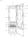
- the clothing treatment device 1 forms a treatment space 10s in which a subject to be processed such as clothing is placed, a cabinet 10 having a front opened, a door 30 which opens and closes the opened front of the cabinet 10, and a machine compartment 20 which is disposed at a lower side of the treatment space 10s and which circulates air with the treatment space.
- a clothing hanger 12 may be disposed in an upper side of the treatment space 10s to hang clothing received in the treatment space 10s, and a shelf 14 in which a small-sized treatment object placed in the treatment space 10s is held may be disposed.
- the clothing hanger 12 may be vibrated by a vibration module (not shown) disposed inside the cabinet 10. According to the vibration of the vibration module, the clothing hanger 12 may shake clothing hanging on the clothing hanger 12 to shake off foreign substances from the clothing.
- the shelf 14 is detachably disposed in the treatment space 10s of the cabinet 10.
- the door 30 includes a door plate 31 which covers the front of the cabinet 10, a presser 38 which is located at an inner surface of the door plate 31 facing the treatment space 10s when the door plate 31 is closed and which is configured to apply pressure to clothing, and a clothing fixing portion 32 which fixes the position of clothing located at the presser 38.
- the clothing fixing portion 32 fixes clothing at the upper side of a presser 38 such that the clothing is stretched downward.
- the door 30 includes a slope 40 disposed below the presser 38 and guiding a condensate flowing down the door 30 to a suction port 22a.
- the slope 40 protrudes obliquely from the inner surface of the door 30 toward the treatment space 10s.
- the slope 40 is formed in an upper side of the machine compartment 20, and a width thereof protruding from the door 30 increases in a downward direction.
- the machine compartment 20 is disposed inside the cabinet 10 and below the treatment space 10s to circulate air of the treatment space.
- the suction port 22a through which air is suctioned into the machine compartment 20 and a discharge port 24a through which air inside the machine compartment 20 is discharged to the processing room 10s are formed in the upper surface facing the treatment space 10s.
- a filter module 100 collecting foreign substances falling to a lower side of the treatment space 10s or filtering out foreign substances in air introduced through the suction port 22a is disposed at an upper side of the machine compartment 200.
- a mounting surface 22 forming a space in which the filter module 100 is mounted and a discharge port cover 24 in which a discharge port 24a is formed are disposed.
- the suction port 22a through which air inside the treatment space 10s is introduced into the machine compartment 20 is formed.
- the discharge port cover 24 may also be disposed to be detachable upwards of the machine compartment 20.
- the filter module 100 is disposed to be detachable upwards of the machine compartment 20 in a state in which the discharge port cover 24 is mounted above the machine compartment 20.
- a front holding portion 25 in which a front end of a lower plate 160 described below is held is dispose at a front of of the suction port 22a of the mounting surface 22.
- the machine compartment 20 includes a front holding portion 25 which is disposed at the front of the suction port 22a on an upper surface and in which the lower plate 160 of the filter module 100 to be described below is held.
- the front holding portion 25 is disposed below the slope 40.
- the front holding portion 25 has a shape that is inclined downward toward a rear, and the suction port 22a is formed at a rear end.
- a handle 118 of a filter unit 110 to be described below is disposed above the front holding portion 25
- the filter module 100 may be disposed above the machine compartment 20 to be substantially parallel to the ground, and the discharge port cover 24 may be disposed above the filter module 100 to be in an inclined shape.
- a fan for cuasing air introduced into the suction port 22a to flow into the discharge port 24a, an air treatment part (not shown) for performing treatment on air introduced into the machine compartment 20, and a steam supply unit (not shown) for generating steam by heating water and then transmitting the generated stem to the treatment space 10s may be disposed inside the machine compartment 20.
- the air treatment part circulates a refrigerant through compression, condensation, expansion, and evaporation processes, such that air introduced through the suction port 22a can be condensed through heat exchange with the refrigerant and heated, thereby transmitting hot and dry air to the discharge port 24a.
- the machine compartment 20 includes a first tank 26 for supplying water to the steam supply unit, and a second tank 28 for storing a condensate created by condensation of air inside the machine compartment 20.
- FIGS. 1 to 10 a filter module of the present disclosure and a configuration associated with the filter module will be described.
- the filter module 100 collects foreign substances contained in air falling from the treatment space 10s or filters out foreign substances flowing to the suction port.
- the filter module 100 is disposed at an upper surface of the machine compartment 20.
- the filter module 100 is disposed at an upper side of the mounting surface 22 of the machine compartment.
- a module cover 130 includes an accommodation space 132 in which the filter unit 110 is disposed, an opening 134 through which the filter unit 110 is to be inserted or withdrawn is formed at a front of the accommodation space 132, and the filter unit 110 is slidably coupled to the module cover 130.
- the filter module 100 includes: the module cover 130 disposed at the upper surface of the machine compartment 20 so that foreign substances of the treatment space 10s falls down; and the filter unit 110 disposed to be withdrawn inwards of the module cover 130 so as to filter out foreign substances that falls to the module cover 130.
- the module cover 130 includes: the lower plate 160 which is disposed at a lower side of the filter unit 110 and which accommodates foreign substances falling down from the filter unit 110, and an upper grille 140 which is coupled to the lower plate 160 to form an accommodation space 132 where the filter unit 110 is accommodated and which covers an upper side of the filter unit 110.
- the lower plate 160 has a plate shape and includes a plate portion 162 having one side in which a suction port corresponding hole 170 is formed, and an edge portion 174 protruding upward from a circumferential surface of the plate portion 162.
- the suction port corresponding hole 170 is disposed above the suction port 22a. At least one rib 172 for strength reinforcement is formed in the suction port corresponding hole 170.
- the lower plate 160 When the filter module 100 is mounted in the filter module mounting surface 22, the lower plate 160 is disposed at a predetermined interval upwards from the filter module mounting surface 22. This is to secure a space in which a condensate created from air containing moisture and flowing in the treatment space 10s is drained to the suction port 22a.
- a locking protrusion 164 At the rear of the plate portion 162, a locking protrusion 164 for fixing a position when the filter unit 110 is inserted into the module cover 130 may be formed.
- the locking protrusion 164 may be disposed adjacent to the edge portion 174 formed at the rear end of the plate portion 162.
- the edge portion 174 may be formed at both ends and a rear end of the plate portion 162. No edge portion is formed at a front end of the plate portion 162 since an opening through which the filter unit 110 is to be withdrawn is formed therein. Foreign substances falling down on the filter module 100 may be collected on the lower plate 160 by the edge portion 174.
- the edge portion 174 disposed at the rear of the plate portion 162 may be formed in a semicircular shape convex outward in order to prevent interference with a fixing guide 150 of the upper grille 140.
- a hinge portion 166 to be hinged with the upper grille 140 is disposed at the rear of each of both ends of the lower plate 160.
- the hinge portion 166 of the lower plate 160 is hinged with a hinge corresponding portion 146 of the upper grille 140.
- the hinge portion 166 may be a hinge pin or a hinge hole to which the hinge pin is connected, and the hinge corresponding portion 146 may be a hinge hole or a hinge pin which corresponds to the hinge pin or the hinge hole.
- the hinge portion 166 of the lower plate 160 has a hinge hole formed therein, and the hinge counter portion 146 of the upper grille 140 has a hinge pin formed therein.
- the hinge portion 166 may be formed behind the edge portion 174 disposed at the both side ends of the plate portion 162.
- a protruding length 146L of the hinge corresponding portion 146 having a hinge pin shape is formed smaller than a depth 166H of the hinge hole formed in the hinge portion 166 and a diameter 166D of the hinge hole. Accordingly, a user is able to easily remove the upper grille 140 from the lower plate 160 by manipulation.
- a coupling portion 168 to be coupled to the upper grille 140 is disposed at the front of each of the both ends of the lower plate 160.
- the coupling portion 168 of the lower plate 160 may be hooked with a coupling corresponding portion 148 of the upper grille 140. Therefore, by the user's manipulation, the coupling portion 168 of the lower plate 160 and the coupling corresponding portion 148 of the upper gril 140 may be coupled or decoupled.
- the coupling portion 168 of the lower plate 160 and the coupling corresponding portion 148 of the upper grille 140 are decoupled, the upper grille 140 rotates along a hinge axis hinged to the rear side, thereby opening the inside of the module cover 130.
- the accommodation space 132 in which the filter unit 110 is disposed may be formed between the lower plate 160 and the upper grille 140.
- the coupling portion 168 of the lower plate 160 has a hook shape, and the coupling corresponding portion 148 of the upper grille 140 may have a shape of a locking protrusion with which that the coupling portion 168 in the hook shape is locked.
- the upper grille 140 is coupled to the lower plate 160 from above the lower plate 160.
- the upper grille 140 includes a grille portion 142 disposed at the upper side of the filter unit 110, a curved surface periphery disposed at both ends of the grille portion 142 and forming a curved surface extending upward in a direction away from the grille portion 142, and a fixing guide 150 disposed at a rear end of the grille portion 142 and inserted into an insertion space 24b of the discharge port cover 24 to fix the filter module 100 to an upper side of the machine compartment 20.
- the upper grille 140 further includes the hinge corresponding portion 146 and the coupling corresponding portion 148, which are in a structure for coupling with the lower plate 160.
- the grille portion 142 may be formed with a plurality of horizontal grills 142a formed in the left and right directions and a plurality of vertical grills 142b formed in the front-rear direction.
- the plurality of horizontal grills 142a may be arranged at short intervals, compared to the plurality of vertical grills 142b.
- the curved end portion 144 are disposed at each of the both ends of the grille portion 142.
- the curved end portion 144 is convex toward the lower side and forms a curved surface toward the upper side in a direction away from the grille portion 142. Accordingly, foreign substances falling from the treatment space may be induced to move to the grille portion 142 along the curved end portion 144.
- the fixing guide 150 protrudes rearward from a rear end of the grille portion 142 and is inserted into the insertion space 24b formed at a lower side of the discharge port cover 24.
- the fixing guide 150 is inserted into the insertion space 24b formed at the lower side of the discharge port cover 24, the module cover 130 or the filter module 100 is stably mounted at the upper side of the machine compartment 20.
- the fixing guide 150 is bent at the rear end of the grille portion 142 to extend downward, and the fixing guide 150 includes a rear cover 152 covering the rear of the lower plate 160, and a rear protrusion 154 bent at a lower end of the rear cover 152 to extend rearward.
- the rear protrusion 154 may have a shape and a size each corresponding to the insertion space 24b, so that the rear protrusion 154 can be inserted into the insertion space 24b formed at the lower side of the discharge port cover 24.
- a lower protruding portion 171 extending in a downward direction and inserted into the suction port 22a is formed in a front of the lower plate 160.
- the lower protruding portion 171 is formed as a circumference of the suction port corresponding hole 170.
- the lower protruding portion 171 may be held in the front holding portion 25.
- the accommodation space 132 in which the filter unit 110 is disposed is formed inside, and the opening 134 through which the filter unit 110 can be withdrawn is formed outside.
- the opening 134 is located above the front holding portion 25. Accordingly, the filter unit 110 inserted through the opening 134 may be inserted and withdrawn in the forward direction even when the module cover 130 is mounted at the upper side of the machine compartment 20.
- the filter unit 110 includes: a filter for filtering out foreign substances; a filter frame 114 fixing the filter 112 and capable of being inserted or withdrawn into and from the accommodation space 132 of the module cover 130; and a handle 118 exposed to an outside of the opening 134 of the module cover 130 when the filter unit 110 is inserted into the module cover 130.
- the filter frame 114 may include a plurality of horizontal frames 115 formed in the left-right direction and a plurality of vertical frames 116 formed in the front-rear direction.
- a sectional view of the filter frame 114 may have a shape in which the length increases in the vertical direction in a direction from the center to both ends for strength reinforcement. Accordingly, the locking groove 115a concave to the center may be formed at a lower side and an upper side.
- the locking protrusion 164 of the lower plate 160 may be inserted into the locking groove 115a formed in a horizontal frame 115 disposed at a rear end. Therefore, when the filter unit 110 is inserted into the accomodation space 132 of the module cover 130, the locking protrusion 164 is caught by the locking groove 115a formed in the horizontal frame 115 disposed at the rear end, thereby fixing the placement of the filter unit 110.
- the handle 118 has a shape extending forward of the filter frame 114.
- the handle 118 is exposed to the front of the opening 134 when the filter unit 110 is mounted in the module cover 130.
- the handle 118 is disposed above the front holding portion 25.
- the handle 118 is disposed below the slope 40.
- the handle 118 includes a handle groove 118a formed in a downward direction from an upper side.
- a handle hole 118b opened in a vertical direction is included at one side of the handle groove 118.
- the filter module is disposed above the upper side of the machine compartment to filter out flowing foreign substances or accommodate falling foreign substances, and thus, there is an advantage that the inside of the treatment space can be maintained clean. Accordingly, it is possible to maintain clothing refreshged in the treatment space.
- the filter module is detachably held at an upper side of the machine compartment, a user can detach the filter module and clean the filter module separately, and thus, there is an advantage that foreign substances received therein can be easily treated.
- the filter module is composed of a module cover and a filter unit and the filter unit is slidingly coupled from the module cover and is disposed capable of being inserted or withdrawn even in a state in which the filter module is mounted at the upper side of the machine compartment, and thus, there is an advantage that a user can easily separate and use the filter unit only.
Description
- The present disclosure relates to a clothing treatment device, and more particularly, to a clothing treatment device in which a filter portion is disposed below the treatment space.
- Clothing treatment devices are apparatuses that treat clothing, e.g. wash and dry clothing and smooth wrinkles in clothing, at home or at laundromats.
- Clothing treatment devices may be classified into a washer for washing clothing, a dryer for drying clothing, a washer/dryer having both a washing function and a drying function, a refresher for refreshing clothing, and a steamer for removing unnecessary wrinkles in clothing.
- The refresher is an apparatus that keep clothing comfortable and fresh. The refresher functions to dry clothing, to supply fragrance to clothing, to prevent the occurrence of static electricity in clothing, or to remove wrinkles from clothing. Therefore, it is possible to refresh clothing located inside the treatment space by the flow of air in the treatment space for processing the clothing.
-
Korean Patent Application No. 1020180156752 - That is, the foreign substances accumulated at the lower side of the treatment space may flow to clothing by the flow of air, thereby causing a problem that the clothing cannot be refreshed.
-
KR 2011 0067754 A -
WO 2019/112384 A1 discloses a garment treatment device which includes a filter to remove foreign substances in the air flowing through the inlet. -
KR 100 732 550 B1 -
DE 197 05 616A1 relates to a fly lint filter unit for a laundry dryer and comprises a filter in the door to the loading opening and at least an additional filter in the heat exchanger. - The present disclosure provides a clothing treatment device capable of removing foreign substances accumulated at a lower side of a treatment space.
- The present disclosure also provides a clothing treatment device capable of easily collecting foreign substances falling down on the lower side of the treatment space so that the foreign substances can be conveniently removed.
- The present disclosure also provides a clothing treatment device capable of maintaining the inside of the treatment space of the clothing treatment device in a refreshed state.
- The objects of the present disclosure are not limited to the aforementioned objects, and other objects which are not mentioned will be clearly understood by those skilled in the art from the following description.
- The clothing treatment device according to the invention, as defined in claim 1, includes: a cabinet forming a treatment space in which clothing is accommodated, the cabinet opened at a front; a door configured to open and close the opened front of the cabinet; a machine compartment disposed below the treatment space in the cabinet and having a suction port and a discharge port, the suction port through which air of the treatment space is suctioned, the discharge port through which air is discharged to the treatment space; and a filter module disposed below the treatment space and configured to filter out foreign substances from air being introduced through the suction port or collect foreign substances falling down from the treatment space to the machine compartment. Accordingly, it is possible to process foreign substances accumulated on the upper side of the machine compartment.
- Specifically, the filter module may include: a module cover disposed at a lower side of the treatment space; and a filter unit disposed inside the module cover so that the filter unit is allowed to be withdrawn toward a front of the module cover when the door opens the opened front of the cabinet, the filter unit which filters out foreign substances falling down on the module cover.
- The filter module may be disposed to be detachable upwards of the machine compartment. Accordingly, a user is able to remove foreign substances accumulated on the filter module or foreign substances filtered out.
- An accommodation space where the filter unit is accommodated and an opening through which the filter unit is to be inserted and withdrawn may be formed in the module cover, and the filter unit may be slidably coupled to the module cover.
- The module cover includes:
a lower plate disposed at a lower side of the filter unit and receiving foreign substances falling down from the filter unit; and an upper grille coupled to the lower plate to form an accommodation space where the filter unit is accommodated. - The lower plate and the upper grille may be hinged to each other at one side and hooked to each other at the other side. Accordingly, it is possible to clean the inside of the module cover by easily opening/closing or separating the inside of the filter cover.
- When the lower plate and the upper grille are coupled, an opening through which the filter unit is to be inserted from or withdrawn toward the front may be formed. Accordingly, it is possible to easily separate, clean, and replace the filter unit only.
- The lower plate includes:
a plate portion having a plate shape and forming a space for collecting foreign substances falling down from the treatment space to an upper side of the machine compartment; and an edge portion protruding upwards from a circumferential surface of the plate portion. The plate portion may have a suction port corresponding hole formed therein, the suction corresponding hole which is opened above the suction port in a vertical direction. Accordingly, a space where foreign substances are accommodated is formed, and air is allowed to flow through the suction port. - A fixing protrusion for fixing a position of the filter unit inserted into the module cover may be formed in an inner end of the lower plate. Accordingly, it is possible to fix the filter unit inserted into the module cover.
- The filter unit may include: a filter configured to filter out foreign substances; and a plurality of filter frames to be inserted into or withdrawn from the accommodation space of the module cover, the plurality of filter frames which is arranged in a grid shape and fixes the filter. A locking groove concave inwards may be formed in one of the plurality of filter frames, so that the fixing protrusion is locked.
- The upper grille may include a grille portion disposed at an upper side of the filter unit and a curved end portion disposed at each of both ends of the grille portion to extend in left and right directions, the curved end portion which forms a curved surface extending upwards in a direction away from the grille portion. Accordingly, it is possible to cause foreign substances falling down from the treatment space to the filter unit through the grille portion.
- A discharge port cover forming a discharge port and disposed obliquely upwards may be disposed at a rear of the filter module, and the upper grille may include a fixing guide disposed at a rear end of the grille portion and inserted into an insertion space formed between the discharge port cover and the machine compartment. Accordingly, the filter module may be fixed to the upper side of the machine compartment.
- A mounting surface in which the filter module is mounted may be formed at an upper side of the machine compartment, and the lower plate may be spaced a predetermined distance from the mounting surface of the machine compartment.
- The door may include a slope formed in an inner surface toward the treatment space and protruding toward the treatment space, and the slope may be located above the filter module when the door closes the treatment space. Accordingly, the filter module may not be intervened even by opening/closing of the door.
- The filter unit may include a handle exposed to a front of the opening when the filter unit is inserted into the module cover. Accordingly, a user is able to easily withdraw or insert the filter unit.
- The machine compartment may include a front holding portion which is formed at a front of the suction port on an upper surface and in which the lower plate is held. Accordingly, the filter module may be held above the machine room.
- When the filter module is mounted at the upper side of the machine compartment, the handle may be located above the front holding portion. Accordingly, even though the filter module is mounted at the upper side of the machine compartment, the filter unit may be easily withdrawn toward the front.
- Details of other embodiments are included in the detailed description and drawings.
-
-
FIG. 1 is a view of a clothing treatment device with a door opened, according to an embodiment of the present disclosure. -
FIG. 2 is a view ofFIG. 1 with a filter module removed. -
FIG. 3 is a perspective view of a filter module according to an embodiment of the present disclosure. -
FIG. 4 is an exploded perspective view of a filter module according to an embodiment of the present disclosure. -
FIG. 5A is a view illustrating a state in which a filter unit is withdrawn from or inserted into a filter cover according to an embodiment of the present disclosure. -
FIG. 5B is a view illustrating a state in which a filter cover is opened according to an embodiment of the present disclosure. -
FIG. 6 is a perspective view of a module cover and a filter unit mounted on a discharge port cover according to an embodiment of the present disclosure. -
FIG. 7 is a view illustrating a cross-sectional view of a filter module and a portion of a discharge port forming surface according to an embodiment of the present disclosure cut in the front-rear direction. -
FIG. 8 is an enlarged view of a portion A ofFIG. 7 . -
FIG. 9 is a view for describing a hinge portion and a hinge corresponding portion of the upper grille and the lower plate according to an embodiment of the present disclosure. -
FIG. 10 is a view for describing a relationship between a filter module, a front of a machine compartment, and a slope of a door according to an embodiment of the present disclosure. - Advantages and features of the inventive concept and methods of accomplishing the same may be understood more readily by reference to the following detailed description of exemplary embodiments and the accompanying drawings. The inventive concept may, however, be embodied in many different forms and should not be construed as being limited to the embodiments set forth herein. Rather, these embodiments are provided so that this disclosure will be thorough and complete and will fully convey the concept of the invention to those skilled in the art, and the inventive concept will only be defined by the appended claims. Like reference numerals refer to like elements throughout the specification.
- Hereinafter, the present disclosure will be described with reference to the drawings for explaining a clothing treatment device according to embodiments of the present disclosure.
- Referring to 1, 2 and 10, overall configurations of a clothing treatment device according to the present embodiment will be schematically described.
- A clothing treatment apparatus 1 of the present disclosure may supply steam or hot air to a treatment object (hereinafter referred to as "clothing"), such as clothing placed in the inside, or may supply dry air at a high temperature. In addition, the clothing treatment device 1 may shake off foreign substances from the clothing by applying vibration to the clothing placed in the inside.
- Referring to
FIG. 1 , the clothing treatment device 1 according to the present disclosure forms atreatment space 10s in which a subject to be processed such as clothing is placed, acabinet 10 having a front opened, adoor 30 which opens and closes the opened front of thecabinet 10, and amachine compartment 20 which is disposed at a lower side of thetreatment space 10s and which circulates air with the treatment space. - Within the
cabinet 10, aclothing hanger 12 may be disposed in an upper side of thetreatment space 10s to hang clothing received in thetreatment space 10s, and ashelf 14 in which a small-sized treatment object placed in thetreatment space 10s is held may be disposed. - The
clothing hanger 12 may be vibrated by a vibration module (not shown) disposed inside thecabinet 10. According to the vibration of the vibration module, theclothing hanger 12 may shake clothing hanging on theclothing hanger 12 to shake off foreign substances from the clothing. Theshelf 14 is detachably disposed in thetreatment space 10s of thecabinet 10. - The
door 30 includes adoor plate 31 which covers the front of thecabinet 10, apresser 38 which is located at an inner surface of thedoor plate 31 facing thetreatment space 10s when thedoor plate 31 is closed and which is configured to apply pressure to clothing, and aclothing fixing portion 32 which fixes the position of clothing located at thepresser 38. Theclothing fixing portion 32 fixes clothing at the upper side of apresser 38 such that the clothing is stretched downward. - The
door 30 includes aslope 40 disposed below thepresser 38 and guiding a condensate flowing down thedoor 30 to asuction port 22a. Theslope 40 protrudes obliquely from the inner surface of thedoor 30 toward thetreatment space 10s. Theslope 40 is formed in an upper side of themachine compartment 20, and a width thereof protruding from thedoor 30 increases in a downward direction. - Referring to
FIG. 2 , themachine compartment 20 is disposed inside thecabinet 10 and below thetreatment space 10s to circulate air of the treatment space. In themachine compartment 20, thesuction port 22a through which air is suctioned into themachine compartment 20 and adischarge port 24a through which air inside themachine compartment 20 is discharged to theprocessing room 10s are formed in the upper surface facing thetreatment space 10s. - Referring to
FIG. 1 , afilter module 100 collecting foreign substances falling to a lower side of thetreatment space 10s or filtering out foreign substances in air introduced through thesuction port 22a is disposed at an upper side of the machine compartment 200. At the upper surface of themachine compartment 20, a mountingsurface 22 forming a space in which thefilter module 100 is mounted and a discharge port cover 24 in which adischarge port 24a is formed are disposed. At one side of the mountingsurface 22, thesuction port 22a through which air inside thetreatment space 10s is introduced into themachine compartment 20 is formed. - The discharge port cover 24 may also be disposed to be detachable upwards of the
machine compartment 20. Thefilter module 100 is disposed to be detachable upwards of themachine compartment 20 in a state in which thedischarge port cover 24 is mounted above themachine compartment 20. - Referring to
FIG. 10 , afront holding portion 25 in which a front end of alower plate 160 described below is held is dispose at a front of of thesuction port 22a of the mountingsurface 22. Themachine compartment 20 includes a front holdingportion 25 which is disposed at the front of thesuction port 22a on an upper surface and in which thelower plate 160 of thefilter module 100 to be described below is held. - The front holding
portion 25 is disposed below theslope 40. The front holdingportion 25 has a shape that is inclined downward toward a rear, and thesuction port 22a is formed at a rear end. Ahandle 118 of afilter unit 110 to be described below is disposed above thefront holding portion 25 - The
filter module 100 may be disposed above themachine compartment 20 to be substantially parallel to the ground, and the discharge port cover 24 may be disposed above thefilter module 100 to be in an inclined shape. - A fan (not shown) for cuasing air introduced into the
suction port 22a to flow into thedischarge port 24a, an air treatment part (not shown) for performing treatment on air introduced into themachine compartment 20, and a steam supply unit (not shown) for generating steam by heating water and then transmitting the generated stem to thetreatment space 10s may be disposed inside themachine compartment 20. - The air treatment part circulates a refrigerant through compression, condensation, expansion, and evaporation processes, such that air introduced through the
suction port 22a can be condensed through heat exchange with the refrigerant and heated, thereby transmitting hot and dry air to thedischarge port 24a. - The
machine compartment 20 includes afirst tank 26 for supplying water to the steam supply unit, and asecond tank 28 for storing a condensate created by condensation of air inside themachine compartment 20. - Referring to
FIGS. 1 to 10 , a filter module of the present disclosure and a configuration associated with the filter module will be described. - Referring to
FIG. 1 , thefilter module 100 collects foreign substances contained in air falling from thetreatment space 10s or filters out foreign substances flowing to the suction port. Thefilter module 100 is disposed at an upper surface of themachine compartment 20. Thefilter module 100 is disposed at an upper side of the mountingsurface 22 of the machine compartment. - Referring to
FIG. 7 , amodule cover 130 includes anaccommodation space 132 in which thefilter unit 110 is disposed, anopening 134 through which thefilter unit 110 is to be inserted or withdrawn is formed at a front of theaccommodation space 132, and thefilter unit 110 is slidably coupled to themodule cover 130. - Referring to
FIGS. 3 and4 , thefilter module 100 includes: themodule cover 130 disposed at the upper surface of themachine compartment 20 so that foreign substances of thetreatment space 10s falls down; and thefilter unit 110 disposed to be withdrawn inwards of themodule cover 130 so as to filter out foreign substances that falls to themodule cover 130. - Referring to
FIGS. 5 and6 , themodule cover 130 includes: thelower plate 160 which is disposed at a lower side of thefilter unit 110 and which accommodates foreign substances falling down from thefilter unit 110, and anupper grille 140 which is coupled to thelower plate 160 to form anaccommodation space 132 where thefilter unit 110 is accommodated and which covers an upper side of thefilter unit 110. - Referring to
FIG. 4 , thelower plate 160 has a plate shape and includes aplate portion 162 having one side in which a suctionport corresponding hole 170 is formed, and anedge portion 174 protruding upward from a circumferential surface of theplate portion 162. - Referring to
FIG. 4 , when thefilter module 100 is mounted in the filtermodule mounting surface 22 of themachine compartment 20, the suctionport corresponding hole 170 is disposed above thesuction port 22a. At least onerib 172 for strength reinforcement is formed in the suctionport corresponding hole 170. - When the
filter module 100 is mounted in the filtermodule mounting surface 22, thelower plate 160 is disposed at a predetermined interval upwards from the filtermodule mounting surface 22. This is to secure a space in which a condensate created from air containing moisture and flowing in thetreatment space 10s is drained to thesuction port 22a. At the rear of theplate portion 162, a lockingprotrusion 164 for fixing a position when thefilter unit 110 is inserted into themodule cover 130 may be formed. The lockingprotrusion 164 may be disposed adjacent to theedge portion 174 formed at the rear end of theplate portion 162. When thefilter unit 110 is inserted into themodule cover 130, the lockingprotrusion 164 is inserted into a lockinggroove 115a of thefilter unit 110, thereby limiting movement of thefilter unit 110. - The
edge portion 174 may be formed at both ends and a rear end of theplate portion 162. No edge portion is formed at a front end of theplate portion 162 since an opening through which thefilter unit 110 is to be withdrawn is formed therein. Foreign substances falling down on thefilter module 100 may be collected on thelower plate 160 by theedge portion 174. - Referring to
FIG. 8 , theedge portion 174 disposed at the rear of theplate portion 162 may be formed in a semicircular shape convex outward in order to prevent interference with a fixingguide 150 of theupper grille 140. - At the rear of each of both ends of the
lower plate 160, ahinge portion 166 to be hinged with theupper grille 140 is disposed. Referring toFIG. 9 , thehinge portion 166 of thelower plate 160 is hinged with ahinge corresponding portion 146 of theupper grille 140. Thehinge portion 166 may be a hinge pin or a hinge hole to which the hinge pin is connected, and thehinge corresponding portion 146 may be a hinge hole or a hinge pin which corresponds to the hinge pin or the hinge hole. - Referring to
FIG. 9 , thehinge portion 166 of thelower plate 160 according to an embodiment of the present disclosure has a hinge hole formed therein, and thehinge counter portion 146 of theupper grille 140 has a hinge pin formed therein. Thehinge portion 166 may be formed behind theedge portion 174 disposed at the both side ends of theplate portion 162. - A protruding
length 146L of thehinge corresponding portion 146 having a hinge pin shape is formed smaller than adepth 166H of the hinge hole formed in thehinge portion 166 and adiameter 166D of the hinge hole. Accordingly, a user is able to easily remove theupper grille 140 from thelower plate 160 by manipulation. - Referring to
FIG. 4 , acoupling portion 168 to be coupled to theupper grille 140 is disposed at the front of each of the both ends of thelower plate 160. Thecoupling portion 168 of thelower plate 160 may be hooked with acoupling corresponding portion 148 of theupper grille 140. Therefore, by the user's manipulation, thecoupling portion 168 of thelower plate 160 and thecoupling corresponding portion 148 of theupper gril 140 may be coupled or decoupled. When thecoupling portion 168 of thelower plate 160 and thecoupling corresponding portion 148 of theupper grille 140 are decoupled, theupper grille 140 rotates along a hinge axis hinged to the rear side, thereby opening the inside of themodule cover 130. - When the
coupling portion 168 of thelower plate 160 and thecoupling corresponding portion 148 of theupper grille 140 are coupled, theaccommodation space 132 in which thefilter unit 110 is disposed may be formed between thelower plate 160 and theupper grille 140. - The
coupling portion 168 of thelower plate 160 has a hook shape, and thecoupling corresponding portion 148 of theupper grille 140 may have a shape of a locking protrusion with which that thecoupling portion 168 in the hook shape is locked. - Referring to
FIG. 4 , theupper grille 140 is coupled to thelower plate 160 from above thelower plate 160. Theupper grille 140 includes agrille portion 142 disposed at the upper side of thefilter unit 110, a curved surface periphery disposed at both ends of thegrille portion 142 and forming a curved surface extending upward in a direction away from thegrille portion 142, and a fixingguide 150 disposed at a rear end of thegrille portion 142 and inserted into aninsertion space 24b of the discharge port cover 24 to fix thefilter module 100 to an upper side of themachine compartment 20. - As described above, the
upper grille 140 further includes thehinge corresponding portion 146 and thecoupling corresponding portion 148, which are in a structure for coupling with thelower plate 160. - The
grille portion 142 may be formed with a plurality ofhorizontal grills 142a formed in the left and right directions and a plurality ofvertical grills 142b formed in the front-rear direction. The plurality ofhorizontal grills 142a may be arranged at short intervals, compared to the plurality ofvertical grills 142b. - The
curved end portion 144 are disposed at each of the both ends of thegrille portion 142. Thecurved end portion 144 is convex toward the lower side and forms a curved surface toward the upper side in a direction away from thegrille portion 142. Accordingly, foreign substances falling from the treatment space may be induced to move to thegrille portion 142 along thecurved end portion 144. - Referring to
FIG. 8 , the fixingguide 150 protrudes rearward from a rear end of thegrille portion 142 and is inserted into theinsertion space 24b formed at a lower side of thedischarge port cover 24. When the fixingguide 150 is inserted into theinsertion space 24b formed at the lower side of thedischarge port cover 24, themodule cover 130 or thefilter module 100 is stably mounted at the upper side of themachine compartment 20. - The fixing
guide 150 is bent at the rear end of thegrille portion 142 to extend downward, and the fixingguide 150 includes arear cover 152 covering the rear of thelower plate 160, and arear protrusion 154 bent at a lower end of therear cover 152 to extend rearward. Therear protrusion 154 may have a shape and a size each corresponding to theinsertion space 24b, so that therear protrusion 154 can be inserted into theinsertion space 24b formed at the lower side of thedischarge port cover 24. - Referring to
FIG 10 , a lower protrudingportion 171 extending in a downward direction and inserted into thesuction port 22a is formed in a front of thelower plate 160. Thelower protruding portion 171 is formed as a circumference of the suctionport corresponding hole 170. Thelower protruding portion 171 may be held in thefront holding portion 25. - Referring to
FIG. 10 , when thelower plate 160 and theupper grille 140 are coupled, theaccommodation space 132 in which thefilter unit 110 is disposed is formed inside, and theopening 134 through which thefilter unit 110 can be withdrawn is formed outside. When themodule cover 130 is mounted at the upper side of themachine compartment 20, theopening 134 is located above thefront holding portion 25. Accordingly, thefilter unit 110 inserted through theopening 134 may be inserted and withdrawn in the forward direction even when themodule cover 130 is mounted at the upper side of themachine compartment 20. - Referring to
FIG. 4 , thefilter unit 110 includes: a filter for filtering out foreign substances; afilter frame 114 fixing thefilter 112 and capable of being inserted or withdrawn into and from theaccommodation space 132 of themodule cover 130; and ahandle 118 exposed to an outside of theopening 134 of themodule cover 130 when thefilter unit 110 is inserted into themodule cover 130. - Referring to
FIG. 4 , thefilter frame 114 may include a plurality ofhorizontal frames 115 formed in the left-right direction and a plurality ofvertical frames 116 formed in the front-rear direction. A sectional view of thefilter frame 114 may have a shape in which the length increases in the vertical direction in a direction from the center to both ends for strength reinforcement. Accordingly, the lockinggroove 115a concave to the center may be formed at a lower side and an upper side. - Referring to
FIG. 8 , the lockingprotrusion 164 of thelower plate 160 may be inserted into the lockinggroove 115a formed in ahorizontal frame 115 disposed at a rear end. Therefore, when thefilter unit 110 is inserted into theaccomodation space 132 of themodule cover 130, the lockingprotrusion 164 is caught by the lockinggroove 115a formed in thehorizontal frame 115 disposed at the rear end, thereby fixing the placement of thefilter unit 110. - Referring to
FIG. 10 , thehandle 118 has a shape extending forward of thefilter frame 114. Thehandle 118 is exposed to the front of theopening 134 when thefilter unit 110 is mounted in themodule cover 130. When thefilter unit 110 is mounted in themodule cover 130, thehandle 118 is disposed above thefront holding portion 25. When thefilter unit 110 is mounted in themodule cover 130, thehandle 118 is disposed below theslope 40. - The
handle 118 includes ahandle groove 118a formed in a downward direction from an upper side. Ahandle hole 118b opened in a vertical direction is included at one side of thehandle groove 118. When thedoor 30 closes thetreatment space 10s, an end protruding toward the treatment space of theslope 40 is located above thehandle groove 118a. - According to the clothing treatment device of the present disclosure, there are one or more of the following effects.
- First, the filter module is disposed above the upper side of the machine compartment to filter out flowing foreign substances or accommodate falling foreign substances, and thus, there is an advantage that the inside of the treatment space can be maintained clean. Accordingly, it is possible to maintain clothing refreshged in the treatment space.
- Second, since the filter module is detachably held at an upper side of the machine compartment, a user can detach the filter module and clean the filter module separately, and thus, there is an advantage that foreign substances received therein can be easily treated.
- Third, the filter module is composed of a module cover and a filter unit and the filter unit is slidingly coupled from the module cover and is disposed capable of being inserted or withdrawn even in a state in which the filter module is mounted at the upper side of the machine compartment, and thus, there is an advantage that a user can easily separate and use the filter unit only.
- The effects of the present disclosure are not limited to the effects mentioned above, and other effects which are not mentioned will be clearly understood by those skilled in the art from the description of the claims.
- In the above, although the preferred embodiments of the present disclosure have been illustrated and described, the present disclosure is not limited to the specific embodiments described above, and the technical field to which the present disclosure pertains without departing from the scope of the present invention as defined in the claims.
Claims (13)
- A clothing treatment device, comprising:a cabinet (10) forming a treatment space in which clothing is accommodated, the cabinet (10) being opened at a front;a door (30) configured to open and close the opened front of the cabinet (10);a machine compartment (20) disposed below the treatment space in the cabinet (10) and having a suction port (22a) and a discharge port (24a), the suction port (22a) through which air of the treatment space is suctioned, the discharge port (24a) through which air is discharged to the treatment space; anda filter module (100) disposed below the treatment space and configured to filter out foreign substances from air being introduced through the suction port (22a) or collect foreign substances falling down from the treatment space to the machine compartment (20),wherein the filter module (100) comprises:a module cover (130) disposed at a lower side of the treatment space; anda filter unit (110) disposed inside the module cover (130), so that the filter unit (110) is allowed to be withdrawn toward a front of the module cover (130) when the door (30) opens the opened front of the cabinet (10), the filter unit (110) configured to filter out foreign substances falling down on the module cover (130),wherein the module cover (130) comprises:a lower plate (160) disposed at a lower side of the filter unit (110), and configured to receive foreign substances falling down from the filter unit (110); andan upper grille (140) coupled to the lower plate (160) to form an accommodation space (132) where the filter unit (110) is accommodated,wherein the lower plate (160) comprises:a plate portion (162) having a plate shape and forming a space for collecting foreign substances falling down from the treatment space to an upper side of the machine compartment (20); andan edge portion (174) protruding upwards from a circumferential surface of the plate portion (162),wherein the plate portion (162) has a suction port corresponding hole (170) formed therein, the suction port corresponding hole (170) is opened above the suction port (22a) in a vertical direction.
- The clothing treatment device of claim 1, wherein the filter module (100) is disposed to be detachable upwards of the machine compartment (20).
- The clothing treatment device of claim 1 or 2,wherein the accommodation space (132) where the filter unit (110) is accommodated and an opening through which the filter unit (110) is insertable and withdrawable are formed in the module cover (130),wherein the filter unit (110) is slidably coupled to the module cover (130).
- The clothing treatment device of any one of claims 1 to 3, wherein the lower plate (160) and the upper grille (140) are hinged to each other at one side and hooked to each other at the other side.
- The clothing treatment device of claim 3 or 4, wherein when the lower plate (160) and the upper grille (140) are coupled, the opening through which the filter unit (110) is insertable from or withdrawable toward the front is formed.
- The clothing treatment device of any one of claims 1 to 5, wherein a fixing protrusion for fixing a position of the filter unit (110) inserted into the module cover (130) is formed in an inner end of the lower plate (160).
- The clothing treatment device of claim 6, wherein the filter unit (110) comprises:a filter configured to filter out foreign substances; anda plurality of filter frames (114) insertable into or withdrawable from the accommodation space (132) of the module cover (130), the plurality of filter frames (114) is arranged in a grid shape and configured to fix the filter,wherein a locking groove (115a) concave inwards is formed in one of the plurality of filter frames (114), so that the fixing protrusion is locked.
- The clothing treatment device of any one of claims 1 to 7, wherein the upper grille (140) comprises a grille portion (142) disposed at an upper side of the filter unit (110) and a curved end portion (144) disposed at each of both ends of the grille portion (142) to extend in left and right directions, the curved end portion (144) which forms a curved surface extending upwards in a direction away from the grille portion (142).
- The clothing treatment device of claim 8,wherein a discharge port cover (24) forming a discharge port (24a) and disposed obliquely upwards is disposed at a rear of the filter module (100),wherein the upper grille (140) includes a fixing guide (150) disposed at a rear end of the grille portion (142) and insertable into an insertion space (24b) formed between the discharge port cover (24) and the machine compartment (20).
- The clothing treatment device of any one of claims 1 to 9,wherein a mounting surface (22) in which the filter module (100) is mounted is formed at an upper side of the machine compartment (20),wherein the lower plate (160) is spaced a predetermined distance from the mounting surface (22) of the machine compartment (20).
- The clothing treatment device of any one of claims 1 to 10, wherein the door (30) comprises:a slope (40) formed in an inner surface toward the treatment space and protruding toward the treatment space,wherein the slope (40) is located above the filter module (100) when the door (30) closes the treatment space.
- The clothing treatment device of any one of claims 5 to 11 when being dependent on claim 3, wherein the filter unit (110) comprises a handle (118) exposed to a front of the opening when the filter unit (110) is inserted into the module cover (130).
- The clothing treatment device of claim 12, wherein the machine compartment (20) comprises a front holding portion (25) which is formed at a front of the suction port (22a) on an upper surface and in which the lower plate (160) is held, wherein when the filter module (100) is mounted at the upper side of the machine compartment (20), the handle (118) is located above the front holding portion (25).
Priority Applications (1)
| Application Number | Priority Date | Filing Date | Title |
|---|---|---|---|
| EP22205953.7A EP4166708A1 (en) | 2019-08-13 | 2020-08-12 | Clothing treatment device |
Applications Claiming Priority (1)
| Application Number | Priority Date | Filing Date | Title |
|---|---|---|---|
| KR1020190099026A KR20210019867A (en) | 2019-08-13 | 2019-08-13 | Apparatus for treating clothes |
Related Child Applications (2)
| Application Number | Title | Priority Date | Filing Date |
|---|---|---|---|
| EP22205953.7A Division-Into EP4166708A1 (en) | 2019-08-13 | 2020-08-12 | Clothing treatment device |
| EP22205953.7A Division EP4166708A1 (en) | 2019-08-13 | 2020-08-12 | Clothing treatment device |
Publications (2)
| Publication Number | Publication Date |
|---|---|
| EP3779025A1 EP3779025A1 (en) | 2021-02-17 |
| EP3779025B1 true EP3779025B1 (en) | 2022-12-21 |
Family
ID=72050703
Family Applications (2)
| Application Number | Title | Priority Date | Filing Date |
|---|---|---|---|
| EP20190653.4A Active EP3779025B1 (en) | 2019-08-13 | 2020-08-12 | Clothing treatment device |
| EP22205953.7A Pending EP4166708A1 (en) | 2019-08-13 | 2020-08-12 | Clothing treatment device |
Family Applications After (1)
| Application Number | Title | Priority Date | Filing Date |
|---|---|---|---|
| EP22205953.7A Pending EP4166708A1 (en) | 2019-08-13 | 2020-08-12 | Clothing treatment device |
Country Status (6)
| Country | Link |
|---|---|
| US (1) | US20210047772A1 (en) |
| EP (2) | EP3779025B1 (en) |
| JP (1) | JP7386970B2 (en) |
| KR (1) | KR20210019867A (en) |
| CN (1) | CN114222838B (en) |
| WO (1) | WO2021029680A1 (en) |
Families Citing this family (1)
| Publication number | Priority date | Publication date | Assignee | Title |
|---|---|---|---|---|
| KR20230174148A (en) * | 2022-06-20 | 2023-12-27 | 엘지전자 주식회사 | A laundry treating apparatus |
Family Cites Families (18)
| Publication number | Priority date | Publication date | Assignee | Title |
|---|---|---|---|---|
| US3513982A (en) | 1967-05-01 | 1970-05-26 | Eastman Kodak Co | Filter arrangement |
| DE19705616A1 (en) * | 1997-02-14 | 1998-08-20 | Miele & Cie | Fly lint filter unit for laundry dryer |
| US6059852A (en) * | 1998-10-08 | 2000-05-09 | Olson; Kenric J. | Plastic injection molded furnace filter |
| JP3618728B2 (en) * | 2002-05-21 | 2005-02-09 | 株式会社東芝 | Washing and drying machine |
| KR101094548B1 (en) * | 2005-01-25 | 2011-12-19 | 엘지전자 주식회사 | Filter of dryer |
| KR100732550B1 (en) * | 2006-05-29 | 2007-06-28 | 삼성전자주식회사 | Clothing dryer |
| KR101070485B1 (en) * | 2008-12-17 | 2011-10-05 | 엘지전자 주식회사 | Dryer and apparatus for removing lint thereof |
| KR101081091B1 (en) * | 2008-12-22 | 2011-11-07 | 엘지전자 주식회사 | Dryer and filtering unit |
| KR101603106B1 (en) * | 2009-03-03 | 2016-03-14 | 엘지전자 주식회사 | Washing machine |
| KR101053631B1 (en) * | 2009-12-15 | 2011-08-03 | 엘지전자 주식회사 | Clothing processing device |
| KR101710390B1 (en) * | 2009-12-15 | 2017-02-27 | 엘지전자 주식회사 | loth treating apparatus |
| CN101832602B (en) | 2010-03-21 | 2013-03-06 | 海信(山东)空调有限公司 | Floor type air conditioner with bottom air inlet function |
| CA2798779C (en) * | 2010-05-07 | 2015-02-10 | Lg Electronics Inc. | Clothes treating apparatus and filter technology |
| KR20120074557A (en) * | 2010-12-28 | 2012-07-06 | 삼성전자주식회사 | Refresh washing machine and method thereof |
| US20150113825A1 (en) * | 2013-10-25 | 2015-04-30 | Richard Goulet | Drying cabinet for clothing and sports equipment |
| JP6169015B2 (en) | 2014-02-24 | 2017-07-26 | 三菱電機株式会社 | Heat exchange ventilator |
| KR101597106B1 (en) | 2014-12-19 | 2016-03-07 | 엘지전자 주식회사 | Apparatus for treating clothes |
| KR101999533B1 (en) * | 2017-12-08 | 2019-10-01 | 엘지전자 주식회사 | Fabric treating apparatus |
-
2019
- 2019-08-13 KR KR1020190099026A patent/KR20210019867A/en not_active Application Discontinuation
-
2020
- 2020-08-12 EP EP20190653.4A patent/EP3779025B1/en active Active
- 2020-08-12 EP EP22205953.7A patent/EP4166708A1/en active Pending
- 2020-08-13 JP JP2022508776A patent/JP7386970B2/en active Active
- 2020-08-13 US US16/992,635 patent/US20210047772A1/en active Pending
- 2020-08-13 WO PCT/KR2020/010708 patent/WO2021029680A1/en active Application Filing
- 2020-08-13 CN CN202080057001.3A patent/CN114222838B/en active Active
Also Published As
| Publication number | Publication date |
|---|---|
| EP3779025A1 (en) | 2021-02-17 |
| CN114222838A (en) | 2022-03-22 |
| CN114222838B (en) | 2024-01-23 |
| JP7386970B2 (en) | 2023-11-27 |
| US20210047772A1 (en) | 2021-02-18 |
| JP2022544270A (en) | 2022-10-17 |
| EP4166708A1 (en) | 2023-04-19 |
| KR20210019867A (en) | 2021-02-23 |
| WO2021029680A1 (en) | 2021-02-18 |
Similar Documents
| Publication | Publication Date | Title |
|---|---|---|
| EP3133203B1 (en) | Clothes dryer | |
| EP1725707B1 (en) | A washer / dryer | |
| EP3814567B1 (en) | Clothes care apparatus | |
| KR100630023B1 (en) | Drum type washing and drying machine | |
| EP2788539B1 (en) | Filter guide having latch device of filter cover and clothes-drying machine using the same | |
| US7251906B2 (en) | Drum type washing and drying machine | |
| US7707858B2 (en) | Washing machine and lint removing apparatus thereof | |
| EP2199453B1 (en) | A household appliance | |
| EP3124676B1 (en) | Method to position a rack in a laundry dryer and laundry dryer including a rack | |
| EP2829653A1 (en) | Laundry drying apparatus | |
| EP3779025B1 (en) | Clothing treatment device | |
| KR101319881B1 (en) | Multiple laundry treating machine | |
| RU2446239C2 (en) | Household dryer for linen | |
| CN113622171B (en) | Clothes treating apparatus | |
| KR20210076777A (en) | Laundry treatment apparatus | |
| GB2300700A (en) | Clothes washing and drying machine | |
| JP6047759B2 (en) | Washing machine | |
| JP7113308B2 (en) | clothes dryer | |
| KR20110009924A (en) | A laundry treatment machine | |
| KR101342364B1 (en) | Steam laundry dryer | |
| EP3112526B1 (en) | Support device for air filters for drying or washing/drying machines, air filter for drying machines or washing/drying machines provided with said support device and drying or washing/drying machine provided with said filter | |
| KR20110127426A (en) | Laundry treating apparatus | |
| KR101629327B1 (en) | Laundry Treating Apparatus | |
| KR101572884B1 (en) | Laundry treating machine | |
| KR20230114637A (en) | Laundry treatment apparatus |
Legal Events
| Date | Code | Title | Description |
|---|---|---|---|
| PUAI | Public reference made under article 153(3) epc to a published international application that has entered the european phase |
Free format text: ORIGINAL CODE: 0009012 |
|
| STAA | Information on the status of an ep patent application or granted ep patent |
Free format text: STATUS: THE APPLICATION HAS BEEN PUBLISHED |
|
| AK | Designated contracting states |
Kind code of ref document: A1 Designated state(s): AL AT BE BG CH CY CZ DE DK EE ES FI FR GB GR HR HU IE IS IT LI LT LU LV MC MK MT NL NO PL PT RO RS SE SI SK SM TR |
|
| AX | Request for extension of the european patent |
Extension state: BA ME |
|
| STAA | Information on the status of an ep patent application or granted ep patent |
Free format text: STATUS: REQUEST FOR EXAMINATION WAS MADE |
|
| 17P | Request for examination filed |
Effective date: 20210330 |
|
| RBV | Designated contracting states (corrected) |
Designated state(s): AL AT BE BG CH CY CZ DE DK EE ES FI FR GB GR HR HU IE IS IT LI LT LU LV MC MK MT NL NO PL PT RO RS SE SI SK SM TR |
|
| GRAP | Despatch of communication of intention to grant a patent |
Free format text: ORIGINAL CODE: EPIDOSNIGR1 |
|
| STAA | Information on the status of an ep patent application or granted ep patent |
Free format text: STATUS: GRANT OF PATENT IS INTENDED |
|
| INTG | Intention to grant announced |
Effective date: 20220701 |
|
| GRAS | Grant fee paid |
Free format text: ORIGINAL CODE: EPIDOSNIGR3 |
|
| GRAA | (expected) grant |
Free format text: ORIGINAL CODE: 0009210 |
|
| STAA | Information on the status of an ep patent application or granted ep patent |
Free format text: STATUS: THE PATENT HAS BEEN GRANTED |
|
| AK | Designated contracting states |
Kind code of ref document: B1 Designated state(s): AL AT BE BG CH CY CZ DE DK EE ES FI FR GB GR HR HU IE IS IT LI LT LU LV MC MK MT NL NO PL PT RO RS SE SI SK SM TR |
|
| REG | Reference to a national code |
Ref country code: GB Ref legal event code: FG4D |
|
| REG | Reference to a national code |
Ref country code: CH Ref legal event code: EP |
|
| REG | Reference to a national code |
Ref country code: DE Ref legal event code: R096 Ref document number: 602020007034 Country of ref document: DE |
|
| REG | Reference to a national code |
Ref country code: AT Ref legal event code: REF Ref document number: 1539118 Country of ref document: AT Kind code of ref document: T Effective date: 20230115 |
|
| REG | Reference to a national code |
Ref country code: IE Ref legal event code: FG4D |
|
| REG | Reference to a national code |
Ref country code: LT Ref legal event code: MG9D |
|
| REG | Reference to a national code |
Ref country code: NL Ref legal event code: MP Effective date: 20221221 |
|
| PG25 | Lapsed in a contracting state [announced via postgrant information from national office to epo] |
Ref country code: SE Free format text: LAPSE BECAUSE OF FAILURE TO SUBMIT A TRANSLATION OF THE DESCRIPTION OR TO PAY THE FEE WITHIN THE PRESCRIBED TIME-LIMIT Effective date: 20221221 Ref country code: NO Free format text: LAPSE BECAUSE OF FAILURE TO SUBMIT A TRANSLATION OF THE DESCRIPTION OR TO PAY THE FEE WITHIN THE PRESCRIBED TIME-LIMIT Effective date: 20230321 Ref country code: LT Free format text: LAPSE BECAUSE OF FAILURE TO SUBMIT A TRANSLATION OF THE DESCRIPTION OR TO PAY THE FEE WITHIN THE PRESCRIBED TIME-LIMIT Effective date: 20221221 Ref country code: FI Free format text: LAPSE BECAUSE OF FAILURE TO SUBMIT A TRANSLATION OF THE DESCRIPTION OR TO PAY THE FEE WITHIN THE PRESCRIBED TIME-LIMIT Effective date: 20221221 |
|
| REG | Reference to a national code |
Ref country code: AT Ref legal event code: MK05 Ref document number: 1539118 Country of ref document: AT Kind code of ref document: T Effective date: 20221221 |
|
| PG25 | Lapsed in a contracting state [announced via postgrant information from national office to epo] |
Ref country code: RS Free format text: LAPSE BECAUSE OF FAILURE TO SUBMIT A TRANSLATION OF THE DESCRIPTION OR TO PAY THE FEE WITHIN THE PRESCRIBED TIME-LIMIT Effective date: 20221221 Ref country code: LV Free format text: LAPSE BECAUSE OF FAILURE TO SUBMIT A TRANSLATION OF THE DESCRIPTION OR TO PAY THE FEE WITHIN THE PRESCRIBED TIME-LIMIT Effective date: 20221221 Ref country code: HR Free format text: LAPSE BECAUSE OF FAILURE TO SUBMIT A TRANSLATION OF THE DESCRIPTION OR TO PAY THE FEE WITHIN THE PRESCRIBED TIME-LIMIT Effective date: 20221221 Ref country code: GR Free format text: LAPSE BECAUSE OF FAILURE TO SUBMIT A TRANSLATION OF THE DESCRIPTION OR TO PAY THE FEE WITHIN THE PRESCRIBED TIME-LIMIT Effective date: 20230322 |
|
| PG25 | Lapsed in a contracting state [announced via postgrant information from national office to epo] |
Ref country code: NL Free format text: LAPSE BECAUSE OF FAILURE TO SUBMIT A TRANSLATION OF THE DESCRIPTION OR TO PAY THE FEE WITHIN THE PRESCRIBED TIME-LIMIT Effective date: 20221221 |
|
| PG25 | Lapsed in a contracting state [announced via postgrant information from national office to epo] |
Ref country code: SM Free format text: LAPSE BECAUSE OF FAILURE TO SUBMIT A TRANSLATION OF THE DESCRIPTION OR TO PAY THE FEE WITHIN THE PRESCRIBED TIME-LIMIT Effective date: 20221221 Ref country code: RO Free format text: LAPSE BECAUSE OF FAILURE TO SUBMIT A TRANSLATION OF THE DESCRIPTION OR TO PAY THE FEE WITHIN THE PRESCRIBED TIME-LIMIT Effective date: 20221221 Ref country code: PT Free format text: LAPSE BECAUSE OF FAILURE TO SUBMIT A TRANSLATION OF THE DESCRIPTION OR TO PAY THE FEE WITHIN THE PRESCRIBED TIME-LIMIT Effective date: 20230421 Ref country code: ES Free format text: LAPSE BECAUSE OF FAILURE TO SUBMIT A TRANSLATION OF THE DESCRIPTION OR TO PAY THE FEE WITHIN THE PRESCRIBED TIME-LIMIT Effective date: 20221221 Ref country code: EE Free format text: LAPSE BECAUSE OF FAILURE TO SUBMIT A TRANSLATION OF THE DESCRIPTION OR TO PAY THE FEE WITHIN THE PRESCRIBED TIME-LIMIT Effective date: 20221221 Ref country code: CZ Free format text: LAPSE BECAUSE OF FAILURE TO SUBMIT A TRANSLATION OF THE DESCRIPTION OR TO PAY THE FEE WITHIN THE PRESCRIBED TIME-LIMIT Effective date: 20221221 Ref country code: AT Free format text: LAPSE BECAUSE OF FAILURE TO SUBMIT A TRANSLATION OF THE DESCRIPTION OR TO PAY THE FEE WITHIN THE PRESCRIBED TIME-LIMIT Effective date: 20221221 |
|
| PG25 | Lapsed in a contracting state [announced via postgrant information from national office to epo] |
Ref country code: SK Free format text: LAPSE BECAUSE OF FAILURE TO SUBMIT A TRANSLATION OF THE DESCRIPTION OR TO PAY THE FEE WITHIN THE PRESCRIBED TIME-LIMIT Effective date: 20221221 Ref country code: PL Free format text: LAPSE BECAUSE OF FAILURE TO SUBMIT A TRANSLATION OF THE DESCRIPTION OR TO PAY THE FEE WITHIN THE PRESCRIBED TIME-LIMIT Effective date: 20221221 Ref country code: IS Free format text: LAPSE BECAUSE OF FAILURE TO SUBMIT A TRANSLATION OF THE DESCRIPTION OR TO PAY THE FEE WITHIN THE PRESCRIBED TIME-LIMIT Effective date: 20230421 Ref country code: AL Free format text: LAPSE BECAUSE OF FAILURE TO SUBMIT A TRANSLATION OF THE DESCRIPTION OR TO PAY THE FEE WITHIN THE PRESCRIBED TIME-LIMIT Effective date: 20221221 |
|
| REG | Reference to a national code |
Ref country code: DE Ref legal event code: R097 Ref document number: 602020007034 Country of ref document: DE |
|
| PLBE | No opposition filed within time limit |
Free format text: ORIGINAL CODE: 0009261 |
|
| STAA | Information on the status of an ep patent application or granted ep patent |
Free format text: STATUS: NO OPPOSITION FILED WITHIN TIME LIMIT |
|
| PG25 | Lapsed in a contracting state [announced via postgrant information from national office to epo] |
Ref country code: DK Free format text: LAPSE BECAUSE OF FAILURE TO SUBMIT A TRANSLATION OF THE DESCRIPTION OR TO PAY THE FEE WITHIN THE PRESCRIBED TIME-LIMIT Effective date: 20221221 |
|
| 26N | No opposition filed |
Effective date: 20230922 |
|
| PGFP | Annual fee paid to national office [announced via postgrant information from national office to epo] |
Ref country code: DE Payment date: 20230705 Year of fee payment: 4 |
|
| PG25 | Lapsed in a contracting state [announced via postgrant information from national office to epo] |
Ref country code: SI Free format text: LAPSE BECAUSE OF FAILURE TO SUBMIT A TRANSLATION OF THE DESCRIPTION OR TO PAY THE FEE WITHIN THE PRESCRIBED TIME-LIMIT Effective date: 20221221 |
|
| PG25 | Lapsed in a contracting state [announced via postgrant information from national office to epo] |
Ref country code: MC Free format text: LAPSE BECAUSE OF FAILURE TO SUBMIT A TRANSLATION OF THE DESCRIPTION OR TO PAY THE FEE WITHIN THE PRESCRIBED TIME-LIMIT Effective date: 20221221 |
|
| REG | Reference to a national code |
Ref country code: CH Ref legal event code: PL |
|
| PG25 | Lapsed in a contracting state [announced via postgrant information from national office to epo] |
Ref country code: MC Free format text: LAPSE BECAUSE OF FAILURE TO SUBMIT A TRANSLATION OF THE DESCRIPTION OR TO PAY THE FEE WITHIN THE PRESCRIBED TIME-LIMIT Effective date: 20221221 |
|
| PG25 | Lapsed in a contracting state [announced via postgrant information from national office to epo] |
Ref country code: LU Free format text: LAPSE BECAUSE OF NON-PAYMENT OF DUE FEES Effective date: 20230812 |