EP3779022A1 - Support assembly and clothes treating apparatus having support assembly - Google Patents
Support assembly and clothes treating apparatus having support assembly Download PDFInfo
- Publication number
- EP3779022A1 EP3779022A1 EP19777077.9A EP19777077A EP3779022A1 EP 3779022 A1 EP3779022 A1 EP 3779022A1 EP 19777077 A EP19777077 A EP 19777077A EP 3779022 A1 EP3779022 A1 EP 3779022A1
- Authority
- EP
- European Patent Office
- Prior art keywords
- supporting
- drum component
- component
- drum
- pieces
- Prior art date
- Legal status (The legal status is an assumption and is not a legal conclusion. Google has not performed a legal analysis and makes no representation as to the accuracy of the status listed.)
- Granted
Links
Images

Classifications
-
- D—TEXTILES; PAPER
- D06—TREATMENT OF TEXTILES OR THE LIKE; LAUNDERING; FLEXIBLE MATERIALS NOT OTHERWISE PROVIDED FOR
- D06F—LAUNDERING, DRYING, IRONING, PRESSING OR FOLDING TEXTILE ARTICLES
- D06F58/00—Domestic laundry dryers
- D06F58/02—Domestic laundry dryers having dryer drums rotating about a horizontal axis
- D06F58/04—Details
-
- D—TEXTILES; PAPER
- D06—TREATMENT OF TEXTILES OR THE LIKE; LAUNDERING; FLEXIBLE MATERIALS NOT OTHERWISE PROVIDED FOR
- D06F—LAUNDERING, DRYING, IRONING, PRESSING OR FOLDING TEXTILE ARTICLES
- D06F58/00—Domestic laundry dryers
- D06F58/02—Domestic laundry dryers having dryer drums rotating about a horizontal axis
- D06F58/04—Details
- D06F58/06—Mountings for the rotating drums
Definitions
- the present invention belongs to the field of laundry processing devices, and in particular relates to a supporting component and a laundry processing device provided with the supporting component.
- a drum-type clothes dryer is provided with a drum for accommodating clothes. Since clothes need to be delivered into the drum, the drum is designed to be open at one end (or two ends). To ensure that the clothes to be dried can be dried uniformly and rapidly, the drum rotates by a motor via belt driving. When the drum rotates, the open end cannot be connected with housing arranged outside the drum through the shaft structure at the shaft center of the drum. Therefore, a drum which can rotate freely is required to effectively support the open end of the drum.
- the manufacturing and assembling manners of the drum supporting wheels can be divided into two types: the first type is that a rolling bearing (standard parts) and a drum hub as a whole are subject to insert molding, and the hub component after insert molding is then subject to the second insert molding with an outer tyre (semihard material); the second type is that the rolling bearing (standard parts) is firstly subject to preassembly with two hub parts of metal plate material (two hub parts of metal plate material clamp the roller therebetween), riveted or spot-welded for fixation through TOX, and then the well-assembled hub component of a metal plate material and the outer tyre (semihard material) are subject to insert molding.
- the first type is that a rolling bearing (standard parts) and a drum hub as a whole are subject to insert molding, and the hub component after insert molding is then subject to the second insert molding with an outer tyre (semihard material);
- the rolling bearing (standard parts) is firstly subject to preassembly with two hub parts
- each positioning roller of the supporting component is in rolling contact with the drum, to support the drum.
- the supporting stability of the supporting component is poor. Therefore, it is a problem to be urgently solved to provide a supporting component which can rapidly recover stable support when the drum jumps.
- the technical problem to be solved in the present invention is to overcome shortcomings of the prior art, and a supporting component and a laundry processing device with the supporting component are provided.
- a supporting component and a laundry processing device with the supporting component are provided.
- the first supporting piece above the drum component supports the drum component in a contacting manner, to correct the deviation of the drum component.
- a supporting component is provided, wherein the supporting component is configured to support a drum component of a laundry processing device, and includes first supporting pieces and second supporting pieces.
- the second supporting pieces support the drum component in a contacting manner, the first supporting pieces and the drum component are arranged at intervals, and at least one first supporting piece is arranged above the drum component.
- At least one first supporting piece is arranged at below the drum component.
- the second supporting pieces are arranged at two sides of a connecting line between the lowest point of the drum component and a center of the drum component.
- the first supporting pieces arranged below the drum component are arranged between the second supporting pieces.
- one first supporting piece is arranged below the drum component, and the oen first supporting piece corresponds to the lowest point of the drum component.
- the second supporting pieces at two sides of the first supporting piece are symmetrical about the connecting line between the first supporting piece and the center of the drum component.
- one first supporting piece is provided below the drum component, two sides of the one first supporting piece are respectively provided with one second supporting piece, and the two second supporting pieces are in bilateral symmetry about the one first supporting piece.
- the first supporting piece corresponds to the lowest point of the drum component.
- An included angle is formed between the connecting line between the first supporting piece above the drum component and the center of the drum component and the connecting line between the highest point of the drum component and the center of the drum component.
- the first supporting pieces are separated from a peripheral wall of the drum component by an equal distance
- the distance between the first supporting piece above the drum component and the peripheral wall of the drum component is not equal to the distance between the first supporting piece below the drum component and the peripheral wall of the drum component.
- the distance between the first supporting piece below the drum component and the peripheral wall of the drum component is greater than or equal to the distance between the first supporting piece above the drum component and the peripheral wall of the drum component.
- the distances between the first supporting pieces below the drum component and the peripheral wall of the drum component are equal.
- At least part of the first supporting pieces are arranged on a same radial section of the drum component.
- all the first supporting pieces are arranged on the same radial section of the drum component.
- all the first supporting pieces and the second supporting pieces are all arranged on the same radial section of the drum component.
- the first supporting pieces and/or the second supporting pieces are rolling pieces, and the rolling pieces are in rolling contact with the drum component.
- the rolling piece is a roller, a ball or a bearing.
- a laundry processing device provided with the above supporting component includes a drum component, wherein the second supporting pieces support the drum component in a contacting manner, the first supporting piece and the drum component are arranged at intervals. At least one first supporting piece is arranged above the drum component. When the drum component performs upward eccentric movement, the first supporting piece arranged above the drum component supports the drum component in a contacting manner.
- the first supporting piece and the second supporting pieces are both corredspond to the front part of the drum component.
- the supporting component further includes a first mounting bracket and a second mounting bracket, the first supporting piece and the second supporting pieces below the drum component are arranged on the first mounting bracket, and the first supporting piece above the drum component are arranged on the second mounting bracket.
- the laundry processing device includes a front supporting plate for supporting and mounting the drum component, and the first mounting bracket and the second mounting bracket are both assembled on the front supporting plate of the laundry processing device.
- the first mounting bracket is provided with an arc notch
- the drum component is arranged in the arc notch
- the first supporting piece and the second supporting pieces below the drum component are arranged along an edge of the arc notch.
- the present invention has the following beneficial effects compared with the prior art: 1. through setting first supporting piece above the drum component, when the drum component performs upward eccentric movement, the first supporting piece above the drum component supports the drum component in a contacting manner, to correct the deviation of the drum component. 2. first supporting pieces are simultaneously arranged above and below the drum component. When the drum component performs eccentric movement, normal operation is rapidly recovered, thereby prolonging the service life of the drum component of the laundry processing device and the bearing part connected with the drum component. 3. the second supporting pieces are set to be in symmetry at two sides of the first supporting piece. When the drum component is eccentric, the drum component is more easily balanced. 4. the mounting space at the highest point of the general drum component is small, the first supporting piece above the drum component is arranged eccentrically for mounting easier.
- a supporting component is provided.
- the supporting component is configured to support an object.
- the supporting component includes a first mounting bracket 103 and a first supporting piece 101 and second supporting pieces 102 arranged on the first mounting bracket 103.
- the second supporting pieces 102 support the object in a contacting manner, and the first supporting piece 101 and the object are arranged at intervals.
- the first supporting piece 101 and the second supporting pieces 102 are all arranged on the first mounting bracket 103, wherein the second supporting pieces 102 support the object in a contacting manner for supporting the object on the supporting component.
- the first supporting piece 101 is in contact with the object, to realize compensation support to the object, and enable the support for the object by the supporting component more stable.
- first supporting piece 101 and/or the second supporting pieces 102 are rolling pieces arranged on the first mounting bracket 103 in a rotatable manner.
- the second supporting pieces 102 are tangent to the same circumference, and the first supporting piece 101 is arranged on an outer side of the circumference.
- the second supporting pieces 102 are rolling pieces, such that the contact support between the object and the second supporting piece 102 is in rolling contact.
- the friction force is smaller, and the stability is favorable.
- the contact support between the first supporting piece 101 and the object is the same as the above principle.
- the second supporting pieces 102 are tangent with the same circumference, and the first supporting piece 101 is arranged at the outer side of the circumference.
- An inner layer of support and an outer layer of support are formed on the supporting piece, such that when the object vibrates or jumps violently, in addition to the second supporting pieces, the first supporting piece is in contact with the object, to provide a compensation supporting force to the object, and enable the object to be more easily balanced.
- the second supporting pieces 102 support the object in a contacting manner, thereby playing a role of positioning support, and being more easily stable.
- the first supporting piece 101 and the second supporting pieces 102 are both rollers.
- the outer side walls of the second supporting pieces 102 are tangent with the same circumference, and the first supporting piece 101 is arranged at the outer side of the circumference.
- the roller is connected with the first mounting bracket 103 through a bolt, and the circular side wall of the roller is in contact with and supports the object.
- the first supporting piece 101 and the second supporting pieces 102 are both balls.
- the peripheral walls of the second supporting pieces 102 are tangent with the same circumference, and the first supporting piece 101 is arranged at the outer side of the circumference.
- the first mounting bracket 103 is provided with a groove, the balls are arranged in the groove, the upper end of the balls protrudes out of the notch of the groove, and the object is supported by the peripheral wall of the ball in a contacting manner.
- the second supporting pieces 102 are arranged at two sides of the first supporting piece 101.
- the second supporting pieces 102 at two sides support the object in a contacting manner, to form supporting points at two sides of the first supporting piece 101, such that the positioning of the object is more accurate, and the object is more easily balanced, and the support of the supporting piece on the object is more stable.
- the first supporting piece 101 is arranged between the second supporting pieces 102, and the compensation support of the first supporting piece 101 on the object is distributed on the second supporting pieces at two sides in a more balanced manner, such that the object is more easily balanced.
- the second supporting pieces 102 are provided, one first supporting piece 101 is provided, and the second supporting pieces 102 are arranged at two sides of the first supporting piece 101.
- the second supporting pieces 102 are symmetrical about the first supporting piece 101, so the structure enables the object to be more stable on the supporting component.
- first supporting piece 101 is provided, two second supporting pieces 102 are provided, and the two second supporting pieces 102 are symmetrical about the connecting line between the first supporting piece 101 and the center of the circumference. That is, the first supporting piece 101 and the two second supporting pieces 102 are arranged to be of an isosceles triangle on the supporting bracket, and the distance from the first supporting piece 101 to the left second supporting piece 102 is equal to the distance from the first supporting piece 101 to the right second supporting piece 102, such that the compensation supporting force generated by the first supporting piece 101 is distributed uniformly on the second supporting pieces 102 at two sides, and the object is more easily balanced.
- the present embodiment relates to a laundry processing device provided with a supporting component of embodiment 1.
- the laundry processing device includes a drum component 100, the supporting component is configured to support the drum component 100.
- the second supporting pieces 102 support the drum component 100 in a contacting manner, and the first supporting piece 101 is separated from the drum component 100 by a certain distance.
- the first supporting piece 101 supports the drum component 100 in a contacting manner.
- the second supporting pieces 102 support the drum component 100 in a contacting manner, to support the drum component 100.
- the drum component 100 easily performs eccentric movement during rotating, then the drum component 100 may possibly jump and deviate from the original movement trail.
- compensation support is provided to the drum component 100, such that the drum component 100 returns to the original movement trail again, thereby improving the stability of the supporting component on the drum component 100, and reducing damage.
- the first supporting piece 101 is a supporting roller 101
- the second supporting pieces 102 are positioning rollers 102.
- the positioning rollers 102 are in rolling contact with the side wall of the drum component 100
- the supporting roller 101 is separated from the side wall of the drum component 100 by a certain distance
- the supporting roller 101 is in rolling contact with the drum component 100 when the drum component 100 performs eccentric movement.
- two positioning rollers 102 are provided, one supporting roller 101 is provided, and two positioning rollers 102 are arranged at two sides of the supporting roller 101.
- the positioning rollers 102 are in rolling contact with the side wall of the drum component 100, the supporting roller 101 is separated from the side wall of the drum component 100 by a certain distance, and the supporting roller 101 is in rolling contact with the drum component 100 when the drum component 100 performs eccentric movement.
- the drum is in a rotating state during operation, and the supporting component is provided with the supporting roller 101 and the positioning rollers 102, so that when the positioning rollers 102 is in rolling contact with the drum component 100, the friction resistance is reduced, the impedance of the positioning roller 102 on the rotating drum component 100 is reduced. At this time, the supporting roller 101 is not in contact with the drum component 100.
- the supporting roller 101 is in rolling contact with the drum component 100, to provide compensation support to the drum component 100, such that the drum component easily returns to be in contact with the positioning roller 102, and the support is more stable.
- the distance between the first supporting piece 101 and the side wall of the drum component 100 is not greater than the largest eccentric distance of the drum component 100. If the distance between the first supporting piece 101 and the side wall of the drum component 100 is too large, even if the drum component 100 is eccentric, the first supporting piece 101 still cannot support the drum component 100. If the distance between the first supporting piece 101 and the side wall of the drum component 100 is too small, then compensation support can be performed on slight eccentricity, and the service life will be influenced with frequent compensations. Therefore, a better compensation supporting effect can be achieved through controlling the distance between the first supporting piece 101 and the side wall of the drum component 100.
- the distance between the peripheral wall of the supporting roller and the side wall of the drum component is 0.5-5mm
- the distance between the peripheral wall of the supporting roller and the side wall of the drum component is 1mm.
- the supporting roller 101 corresponds to the lowest point of the drum component, and the positioning rollers 102 at two sides of the supporting roller are symmetrical about a straight line which passes through the center of the supporting roller 101 and the center of the drum component 100.
- two positioning rollers 102 are provided.
- the two positioning rollers are respectively arranged at two sides of the supporting roller, and are symmetrical about the straight line which passes through the center of the supporting roller and the center of the drum component, such that two positioning rollers 102 are arranged on the same vertical height.
- first mounting bracket 103 is provided with an arc notch 106, and the drum component 100 is arranged in the arc notch 106 of the first mounting bracket 103.
- the supporting roller 101 and the positioning rollers 102 are both distributed along an edge of the arc notch 106, the second supporting pieces 102 support the outer wall of the drum component 100 in a contacting manner, and the first supporting piece 101 is separated from the outer wall of the drum component 100 by a certain distance.
- An arc notch 106 is set for accommodating the drum component 100 and setting of the supporting roller 101 and the positioning rollers 102.
- the supporting roller 101 and the positioning rollers 102 are distributed along the edge of the arc notch 106.
- the supporting roller 101 is arranged in the middle of the arc notch 106, and the positioning rollers 102 are arranged at two ends of the arc notch 106.
- the supporting component is arranged below the drum component 100.
- the supporting component is arranged below the front of the drum component 100.
- the supporting component is arranged below the front of the drum component 100 for supporting more stably.
- first mounting bracket 103 is provided with a buffer supporting part which is configured to buffer the impact force of the drum component 100 on the first supporting piece 101.
- the first mounting bracket 103 includes a body and a triangular bracket.
- the triangular bracket and the body are molded to form a buffer supporting part, and the first supporting piece 101 is arranged at the vertex position of the triangular bracket.
- the laundry processing device includes a dual-drum washing machine, a drum washing machine or a dryer.
- a washing-drying machine includes a box 105, and a drum component 100 and a supporting component arranged in the box 105.
- the rear part of the drum component 100 is connected with the driving device which drives the drum component 100 to rotate, and the front part is suspended.
- a supporting component is arranged below the drum component 100, such that the drum component 100 is more stable in the rotating process.
- the supporting component is arranged below the front of the drum component 100.
- the eccentric distance at this position is the largest.
- the drum component 100 is more easily balanced.
- the supporting component includes a first mounting bracket 103, two positioning rollers 102 and one supporting roller 101.
- the positioning rollers 102 and the supporting roller 101 are arranged on the first mounting bracket 103 in a rotatable manner.
- the rotating shafts of the positioning roller 102, the supporting roller 101 and the drum component 100 are in parallel with each other, and the positioning roller 102, the supporting roller 101 and the drum component 100 are arranged in the same plane.
- the upper part of the first mounting bracket 103 is provided with an arc notch 106 with an upward opening.
- Two positioning rollers 102 and one supporting roller 101 are distributed along an arc edge of the arc notch 106, and two positioning rollers 102 and one supporting roller 101 all protrude out of the edge of the arc notch 106.
- the supporting roller 101 is arranged in the middle of the arc notch 106, and corresponds to the lowest point of the drum component 100, and two positioning rollers 102 are arranged at two ends of the arc notch 106.
- Two positioning rollers 102 are in bilateral symmetry about a straight line which passes through the center of the supporting roller 101 and the circle center of the drum component 100. That is, two positioning rollers 102 are on one circumference and are arranged on the same vertical height. Two positioning rollers 102 are arranged on the same vertical height. Two positioning rollers 102 are lower than the center of the drum component 100.
- the drum component 100 is arranged at the inner side of the arc notch 106.
- the positioning rollers 102 support the outer wall of the drum component 100 in a contacting manner, and the supporting roller 101 is separated from the drum component 100 by a certain distance.
- the supporting roller 101 is in contact with the drum component 100 to support the drum component 100.
- the distance L between the peripheral wall of the supporting roller and the side wall of the drum component is 1mm.
- a front supporting plate 107 is arranged inside the box, and the first mounting bracket 103 is mounted on the front supporting plate 107.
- the supporting roller is only arranged below the drum component, so that when the drum component performs eccentric movement, compensation support cannot be applied to the upper part of the drum component.
- at least one supporting piece is arranged at the upper part of the drum component.
- the first supporting piece 101 is only arranged below the drum component 100.
- the drum component 100 performs eccentric movement, compensation support cannot be applied to the upper part of the drum component 100.
- at least one first supporting piece 101 is arranged at the upper part of the drum component 100.
- a supporting component is provided.
- the supporting component is configured to support the drum component 100 of the laundry processing device, and includes first supporting pieces 101 and second supporting pieces 102.
- the second supporting pieces 102 support the drum component 100 in a contacting manner, and the first supporting pieces 101 and the drum component 100 are arranged at intervals.
- At least one first supporting piece 101 is arranged at the upper part of the drum component 100.
- the second supporting pieces 102 support the drum component 100 in a contacting manner, such that the drum component 100 is supported on the supporting component. Under normal conditions, the first supporting piece 101 is not in contact with the drum component 100. When the drum component 100 performs eccentric movement, the first supporting piece 101 is in contact with the drum component 100, to support the drum component 100 and play an effect of correcting the deviation. Through setting a first supporting piece 101 above the drum component 100, when the drum component 100 performs upward eccentric movement, the first supporting piece 101 is in contact with the drum component 100, to produce a downward force to correct the deviation.
- At least one first supporting piece 101 is arranged at the lower part of the drum component 100, the second supporting pieces 102 are arranged at two sides of the connecting line between the lowest point of the drum component 100 and the center of the drum component 100, and the first supporting piece 101 arranged below the drum component 100 is arranged between multiple second supporting pieces 102.
- the first supporting pieces 101 are simultaneously arranged above and below the drum component 100.
- the drum component 100 performs eccentric movement, normal operation is rapidly recovered, to prolong the service life of the drum component 100 of the laundry processing device and the bearing part connected with the drum component 100.
- a first supporting piece is arranged below the drum component, and the first supporting piece corresponds to the lowest point of the drum component.
- the second supporting pieces 102 at two sides of the first supporting piece 101 are symmetrical about the connecting line between the first supporting piece 101 and the circle center of the drum component 100.
- the second supporting pieces 102 are set to be symmetrical at two sides of the first supporting piece 101.
- a first supporting piece 101 is arranged below the drum component 100, and each of the two sides of the first supporting piece 101 is respectively provided with one second supporting piece 102.
- the two second supporting pieces 102 are in bilateral symmetry about the first supporting piece 101.
- a certain included angle is formed between the connecting line between the first supporting piece 101 above the drum component 100 and the circle center of the drum component 100 and the connecting line between the highest point of the drum component 100 and the circle center of the drum component 100.
- the mounting space at the highest point of the drum component 100 is small, so when the first supporting piece 101 above the drum component 100 is set to be eccentric, mounting is easier.
- each first supporting piece 101 and the peripheral wall of the drum component 100 can be equal, and each supporting piece 101 supports the drum component 100 when the drum component 100 produces the same eccentric distance.
- the distance between each first supporting piece 101 and the peripheral wall of the drum component 100 can be different, for example, at a certain position.
- the influence on the shaft is larger when the drum component 100 is eccentric at a position.
- the distance between the first supporting piece 101 and the peripheral wall of the drum component 100 is small at the position, otherwise, the distance set is large.
- each first supporting piece 101 is separated from the peripheral wall of the drum component 100 by an equal distance.
- the distance between the first supporting piece 101 above the drum component 100 and the peripheral wall of the drum component 100 is equal to the distance between the first supporting piece 101 below the drum component 100 and the peripheral wall of the drum component 100.
- the distance between the first supporting piece 101 above the drum component 100 is different from the distance between the first supporting piece 101 below the drum component 100 and the peripheral wall of the drum component 100.
- the distance between the first supporting piece 101 below the drum component 100 and the peripheral wall of the drum component 100 is larger than or equal to the distance between the first supporting piece 101 above the drum component 100 and the peripheral wall of the drum component 100.
- the upward eccentric distance of the drum component 100 is small. Therefore, the distance between the first supporting piece 101 above the drum component 100 and the peripheral wall of the drum component 100 is set to be small, and the effect of correcting the deviation is better.
- the spaces between the first supporting pieces 101 below the drum component 100 and the peripheral wall of the drum component 100 are the same.
- first supporting pieces 101 are arranged on the same radial section of the drum component 100. In this way, the supporting force generated by the part of the first supporting pieces 101 is on the same plane, and is more easily balanced.
- the first supporting pieces 101 are divided into two groups, and the two groups of supporting pieces 101 are arranged respectively at the front and rear of the second supporting piece 102.
- all the first supporting pieces 101 are arranged on the same radial section of the drum component 100.
- all the first supporting pieces 101 and the second supporting pieces 102 are respectively arranged on the same radial section of the drum component 100.
- first supporting pieces 101 and/or the second supporting pieces 102 are rolling pieces, and the rolling pieces are in rolling contact with the drum component 100.
- the rolling piece is a roller, a ball or a bearing.
- the friction force is reduced, and the service life is prolonged.
- a laundry processing device provided with the supporting component of embodiment 4 includes a drum component 100, the second supporting pieces 102 for supporting the drum component 100 in a contacting manner, and the first supporting piece 101 being separated from the drum component 100. At least one first supporting piece 101 is arranged above the drum component. When the drum component 100 performs upward eccentric movement, the first supporting piece 101 above the drum component 100 supports the drum component 100 in a contacting manner.
- the first supporting piece and the second supporting piece are both corresponding to the front part of the drum component.
- the supporting piece further includes a first mounting bracket 103 and a second mounting bracket 104.
- the first supporting piece 101 and the second supporting piece 102 arranged below the drum component 100 are arranged on the first mounting bracket 103.
- the first supporting piece 101 arranged above the drum component 100 is arranged on the second mounting bracket 104.
- the laundry processing device includes a front supporting plate 107 configured to support and mount the drum component, and the first mounting bracket 103 and the second mounting bracket 104 are both assembled on the front supporting plate 107 of the laundry processing device.
- the first mounting bracket 103 and the second mounting bracket 104 are both assembled with the laundry processing device. Two mounting brackets are arranged to facilitate mounting and reduce materials.
- the first mounting bracket is provided with an arc notch, the drum component is arranged in the arc notch, and the first supporting pieces and the second supporting pieces arranged below the drum component are arranged along the edge of the arc notch.
- a clothes dryer provided with the supporting structure is taken as an example for specific explanation below.
- a dryer includes a drum component 100 and a supporting component which supports the drum component.
- a clothes delivery opening is formed on the front part of the drum component 100.
- the rear part of the drum component 100 is connected with an output shaft of the driving device, and the supporting component is supported at the front part of the drum component 100.
- the supporting component includes a first mounting bracket 103, a second mounting bracket 104, two second supporting pieces 102 and two first supporting pieces 101.
- the second supporting pieces 102 are positioning rollers, and the first supporting pieces 101 are supporting rollers.
- the first mounting bracket 103 is a tripod, and an arc notch 106 is formed at the upper part of the tripod 103.
- the tripod 103 is arranged below the front part of the drum component 100.
- the first supporting bracket 103 and the second supporting bracket 104 are both mounted with the front supporting plate 107 through screws.
- Two positioning rollers 102 and one supporting roller 101 are arranged along the edge of the arc notch 106.
- Two positioning rollers 102 and one supporting roller 101 are mounted on the tripod 103 rotatably through bolts.
- Two positioning rollers 102 are arranged at two sides of the supporting roller 101.
- the drum component 100 is in rolling contact with the two positioning rollers 102, the supporting roller 101 corresponds to the lowest point of the drum component 100, and two positioning rollers 102 are in bilateral symmetry about the connecting line between the supporting roller 101 and the center of the drum component 100.
- the distance between the supporting roller 101 and the peripheral wall of the drum component 100 is L.
- the other supporting roller 101 is arranged on the second mounting bracket 104, and the second mounting bracket 104 is arranged above the drum component 100, such that the supporting roller 101 is arranged above the drum component 100.
- the distance distance between the supporting roller 101 and the peripheral wall of the drum component 100 is also L.
- the radius of the supporting roller 101 is equal to the radius of the positioning roller 102.
- Two positioning rollers 102 are arranged in the same radial surface of the drum component 100, and two supporting rollers 101 are arranged in the same radial surface of the drum component 100.
- the two radial surfaces are coincided, that is, the two positioning rollers 102 and the two supporting rollers 101 are coplanar.
- the distance between the first supporting piece 101 and the side wall of the drum component 100 is not larger than the largest eccentric distance of the drum component 100.
- the distance between the peripheral wall of the supporting roller 101 and the side wall of the drum component 100 is 0.5-5mm.
- the distance between the peripheral wall of the supporting roller 101 and the side wall of the drum component 100 is 1mm.
Landscapes
- Engineering & Computer Science (AREA)
- Textile Engineering (AREA)
- Detail Structures Of Washing Machines And Dryers (AREA)
- Main Body Construction Of Washing Machines And Laundry Dryers (AREA)
Abstract
Description
- The present invention belongs to the field of laundry processing devices, and in particular relates to a supporting component and a laundry processing device provided with the supporting component.
- A drum-type clothes dryer is provided with a drum for accommodating clothes. Since clothes need to be delivered into the drum, the drum is designed to be open at one end (or two ends). To ensure that the clothes to be dried can be dried uniformly and rapidly, the drum rotates by a motor via belt driving. When the drum rotates, the open end cannot be connected with housing arranged outside the drum through the shaft structure at the shaft center of the drum. Therefore, a drum which can rotate freely is required to effectively support the open end of the drum.
- In the field of existing drum clothes dryers, the manufacturing and assembling manners of the drum supporting wheels can be divided into two types: the first type is that a rolling bearing (standard parts) and a drum hub as a whole are subject to insert molding, and the hub component after insert molding is then subject to the second insert molding with an outer tyre (semihard material); the second type is that the rolling bearing (standard parts) is firstly subject to preassembly with two hub parts of metal plate material (two hub parts of metal plate material clamp the roller therebetween), riveted or spot-welded for fixation through TOX, and then the well-assembled hub component of a metal plate material and the outer tyre (semihard material) are subject to insert molding.
- At present, each positioning roller of the supporting component is in rolling contact with the drum, to support the drum. However, when the drum performs eccentric movement, the supporting stability of the supporting component is poor. Therefore, it is a problem to be urgently solved to provide a supporting component which can rapidly recover stable support when the drum jumps.
- In view of this, the present invention is hereby proposed.
- The technical problem to be solved in the present invention is to overcome shortcomings of the prior art, and a supporting component and a laundry processing device with the supporting component are provided. Through setting a first supporting piece above the drum component, when the drum component performs upward eccentric movement, the first supporting piece above the drum component supports the drum component in a contacting manner, to correct the deviation of the drum component.
- In order to solve the above technical problem, a basic conception of the technical solution adopted in the present invention is as follows.
- A supporting component is provided, wherein the supporting component is configured to support a drum component of a laundry processing device, and includes first supporting pieces and second supporting pieces. The second supporting pieces support the drum component in a contacting manner, the first supporting pieces and the drum component are arranged at intervals, and at least one first supporting piece is arranged above the drum component.
- At least one first supporting piece is arranged at below the drum component. The second supporting pieces are arranged at two sides of a connecting line between the lowest point of the drum component and a center of the drum component. The first supporting pieces arranged below the drum component are arranged between the second supporting pieces.
- Preferably, one first supporting piece is arranged below the drum component, and the oen first supporting piece corresponds to the lowest point of the drum component.
- The second supporting pieces at two sides of the first supporting piece are symmetrical about the connecting line between the first supporting piece and the center of the drum component.
- Preferably, one first supporting piece is provided below the drum component, two sides of the one first supporting piece are respectively provided with one second supporting piece, and the two second supporting pieces are in bilateral symmetry about the one first supporting piece.
- More preferably, the first supporting piece corresponds to the lowest point of the drum component.
- An included angle is formed between the connecting line between the first supporting piece above the drum component and the center of the drum component and the connecting line between the highest point of the drum component and the center of the drum component.
the first supporting pieces are separated from a peripheral wall of the drum component by an equal distance, - Alternatively the distance between the first supporting piece above the drum component and the peripheral wall of the drum component is not equal to the distance between the first supporting piece below the drum component and the peripheral wall of the drum component.
- Preferably, the distance between the first supporting piece below the drum component and the peripheral wall of the drum component is greater than or equal to the distance between the first supporting piece above the drum component and the peripheral wall of the drum component.
- More preferably, the distances between the first supporting pieces below the drum component and the peripheral wall of the drum component are equal.
- At least part of the first supporting pieces are arranged on a same radial section of the drum component.
- Preferably, all the first supporting pieces are arranged on the same radial section of the drum component.
- More preferably, all the first supporting pieces and the second supporting pieces are all arranged on the same radial section of the drum component.
- The first supporting pieces and/or the second supporting pieces are rolling pieces, and the rolling pieces are in rolling contact with the drum component.
- Preferably, the rolling piece is a roller, a ball or a bearing.
- A laundry processing device provided with the above supporting component includes a drum component, wherein the second supporting pieces support the drum component in a contacting manner, the first supporting piece and the drum component are arranged at intervals. At least one first supporting piece is arranged above the drum component. When the drum component performs upward eccentric movement, the first supporting piece arranged above the drum component supports the drum component in a contacting manner.
- Preferably, the first supporting piece and the second supporting pieces are both corredspond to the front part of the drum component.
- The supporting component further includes a first mounting bracket and a second mounting bracket, the first supporting piece and the second supporting pieces below the drum component are arranged on the first mounting bracket, and the first supporting piece above the drum component are arranged on the second mounting bracket.
the laundry processing device includes a front supporting plate for supporting and mounting the drum component, and the first mounting bracket and the second mounting bracket are both assembled on the front supporting plate of the laundry processing device. - The first mounting bracket is provided with an arc notch, the drum component is arranged in the arc notch, and the first supporting piece and the second supporting pieces below the drum component are arranged along an edge of the arc notch.
- After the above technical solution is adopted, the present invention has the following beneficial effects compared with the prior art: 1. through setting first supporting piece above the drum component, when the drum component performs upward eccentric movement, the first supporting piece above the drum component supports the drum component in a contacting manner, to correct the deviation of the drum component. 2. first supporting pieces are simultaneously arranged above and below the drum component. When the drum component performs eccentric movement, normal operation is rapidly recovered, thereby prolonging the service life of the drum component of the laundry processing device and the bearing part connected with the drum component. 3. the second supporting pieces are set to be in symmetry at two sides of the first supporting piece. When the drum component is eccentric, the drum component is more easily balanced. 4. the mounting space at the highest point of the general drum component is small, the first supporting piece above the drum component is arranged eccentrically for mounting easier.
- A further detailed description will be given below on specific embodiments of the present invention in combination with accompanying drawings.
- As a part of the present invention, accompanying drawings are used for providing a further understanding of the present invention. Schematic embodiments and descriptions thereof of the present invention are used for explaining the present invention, rather than constituting an improper limit to the present invention. Obviously, accompanying drawings described below are merely some embodiments, for those skilled in the art, other drawings can be obtained based on these drawings without any creative effort. In the drawings:
-
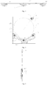
Fig. 1 is a structural schematic diagram of a front view of a laundry processing device of the present invention; -
Fig. 2 is a structural schematic diagram of a side view of a supporting component inFig. 1 of the present invention; -
Fig. 3 is a structural schematic diagram of a top view of a supporting component inFig. 1 of the present invention; -
Fig. 4 is a structural schematic diagram of another laundry processing device of the present invention; -
Fig. 5 is a structural schematic diagram of a side view of a supporting component inFig. 4 of the present invention. - Reference numerals in the figures: 100,
drum component 101, first supporting piece, supportingroller 102, second supporting piece,positioning roller 103, first mounting bracket,tripod 104,second mounting bracket 105,box 106,arc notch 107, front supporting plate. - It should be noted that, these drawings and text descriptions are not aiming at limiting a conception range of the present invention in any form, but to describe concepts of the present invention for those skilled in the art with reference to specific embodiments.
- In order to understand more clearly the object, technical solutions and advantages of the embodiments in the present invention, a clear and complete description is given below on technical solutions in the embodiments in combination with accompanying drawings in the embodiments of the present invention. The following embodiments are used for describing the present invention, rather than for limiting the scope of the present invention.
- As shown in
Fig. 1 to Fig. 3 , a supporting component is provided. The supporting component is configured to support an object. The supporting component includes afirst mounting bracket 103 and a first supportingpiece 101 and second supportingpieces 102 arranged on thefirst mounting bracket 103. The second supportingpieces 102 support the object in a contacting manner, and the first supportingpiece 101 and the object are arranged at intervals. - The first supporting
piece 101 and the second supportingpieces 102 are all arranged on thefirst mounting bracket 103, wherein the second supportingpieces 102 support the object in a contacting manner for supporting the object on the supporting component. When an object moves towards the supporting component under a great force, in addition to support of the second supporting pieces on the object, at this time, the first supportingpiece 101 is in contact with the object, to realize compensation support to the object, and enable the support for the object by the supporting component more stable. - Further, the first supporting
piece 101 and/or the second supportingpieces 102 are rolling pieces arranged on thefirst mounting bracket 103 in a rotatable manner. The second supportingpieces 102 are tangent to the same circumference, and the first supportingpiece 101 is arranged on an outer side of the circumference. - The second supporting
pieces 102 are rolling pieces, such that the contact support between the object and the second supportingpiece 102 is in rolling contact. The friction force is smaller, and the stability is favorable. The contact support between the first supportingpiece 101 and the object is the same as the above principle. - The second supporting
pieces 102 are tangent with the same circumference, and the first supportingpiece 101 is arranged at the outer side of the circumference. An inner layer of support and an outer layer of support are formed on the supporting piece, such that when the object vibrates or jumps violently, in addition to the second supporting pieces, the first supporting piece is in contact with the object, to provide a compensation supporting force to the object, and enable the object to be more easily balanced. - The second supporting
pieces 102 support the object in a contacting manner, thereby playing a role of positioning support, and being more easily stable. - Solution 1, the first supporting
piece 101 and the second supportingpieces 102 are both rollers. The outer side walls of the second supportingpieces 102 are tangent with the same circumference, and the first supportingpiece 101 is arranged at the outer side of the circumference. Specifically, the roller is connected with thefirst mounting bracket 103 through a bolt, and the circular side wall of the roller is in contact with and supports the object. - Solution 2, the first supporting
piece 101 and the second supportingpieces 102 are both balls. The peripheral walls of the second supportingpieces 102 are tangent with the same circumference, and the first supportingpiece 101 is arranged at the outer side of the circumference. Specifically, thefirst mounting bracket 103 is provided with a groove, the balls are arranged in the groove, the upper end of the balls protrudes out of the notch of the groove, and the object is supported by the peripheral wall of the ball in a contacting manner. - Further, the second supporting
pieces 102 are arranged at two sides of the first supportingpiece 101. The second supportingpieces 102 at two sides support the object in a contacting manner, to form supporting points at two sides of the first supportingpiece 101, such that the positioning of the object is more accurate, and the object is more easily balanced, and the support of the supporting piece on the object is more stable. The first supportingpiece 101 is arranged between the second supportingpieces 102, and the compensation support of the first supportingpiece 101 on the object is distributed on the second supporting pieces at two sides in a more balanced manner, such that the object is more easily balanced. - Solution 1, the second supporting
pieces 102 are provided, one first supportingpiece 101 is provided, and the second supportingpieces 102 are arranged at two sides of the first supportingpiece 101. - Solution 2, multiple first supporting
pieces 101 and second supportingpieces 102 are provided, and at least one supportingpiece 101 is arranged between any two adjacent second supportingpieces 102. - In a further solution, the second supporting
pieces 102 are symmetrical about the first supportingpiece 101, so the structure enables the object to be more stable on the supporting component. - For example, one first supporting
piece 101 is provided, two second supportingpieces 102 are provided, and the two second supportingpieces 102 are symmetrical about the connecting line between the first supportingpiece 101 and the center of the circumference. That is, the first supportingpiece 101 and the two second supportingpieces 102 are arranged to be of an isosceles triangle on the supporting bracket, and the distance from the first supportingpiece 101 to the left second supportingpiece 102 is equal to the distance from the first supportingpiece 101 to the right second supportingpiece 102, such that the compensation supporting force generated by the first supportingpiece 101 is distributed uniformly on the second supportingpieces 102 at two sides, and the object is more easily balanced. - As shown in
Fig. 1 to Fig. 3 , the present embodiment relates to a laundry processing device provided with a supporting component of embodiment 1. The laundry processing device includes adrum component 100, the supporting component is configured to support thedrum component 100. The second supportingpieces 102 support thedrum component 100 in a contacting manner, and the first supportingpiece 101 is separated from thedrum component 100 by a certain distance. When thedrum component 100 performs eccentric movement, the first supportingpiece 101 supports thedrum component 100 in a contacting manner. - When the
drum component 100 rotates, the second supportingpieces 102 support thedrum component 100 in a contacting manner, to support thedrum component 100. However, if clothes inside the drum component are not distributed uniformly, thedrum component 100 easily performs eccentric movement during rotating, then thedrum component 100 may possibly jump and deviate from the original movement trail. Through setting the first supportingpiece 101 which supports thedrum component 100 in a contacting manner when thedrum component 100 performs eccentric movement, compensation support is provided to thedrum component 100, such that thedrum component 100 returns to the original movement trail again, thereby improving the stability of the supporting component on thedrum component 100, and reducing damage. - Further, the first supporting
piece 101 is a supportingroller 101, the second supportingpieces 102 are positioningrollers 102. Thepositioning rollers 102 are in rolling contact with the side wall of thedrum component 100, the supportingroller 101 is separated from the side wall of thedrum component 100 by a certain distance, and the supportingroller 101 is in rolling contact with thedrum component 100 when thedrum component 100 performs eccentric movement. - Specifically, two
positioning rollers 102 are provided, one supportingroller 101 is provided, and twopositioning rollers 102 are arranged at two sides of the supportingroller 101. Thepositioning rollers 102 are in rolling contact with the side wall of thedrum component 100, the supportingroller 101 is separated from the side wall of thedrum component 100 by a certain distance, and the supportingroller 101 is in rolling contact with thedrum component 100 when thedrum component 100 performs eccentric movement. - The drum is in a rotating state during operation, and the supporting component is provided with the supporting
roller 101 and thepositioning rollers 102, so that when thepositioning rollers 102 is in rolling contact with thedrum component 100, the friction resistance is reduced, the impedance of thepositioning roller 102 on therotating drum component 100 is reduced. At this time, the supportingroller 101 is not in contact with thedrum component 100. When thedrum component 100 performs eccentric movement, the supportingroller 101 is in rolling contact with thedrum component 100, to provide compensation support to thedrum component 100, such that the drum component easily returns to be in contact with thepositioning roller 102, and the support is more stable. - Further, the distance between the first supporting
piece 101 and the side wall of thedrum component 100 is not greater than the largest eccentric distance of thedrum component 100. If the distance between the first supportingpiece 101 and the side wall of thedrum component 100 is too large, even if thedrum component 100 is eccentric, the first supportingpiece 101 still cannot support thedrum component 100. If the distance between the first supportingpiece 101 and the side wall of thedrum component 100 is too small, then compensation support can be performed on slight eccentricity, and the service life will be influenced with frequent compensations. Therefore, a better compensation supporting effect can be achieved through controlling the distance between the first supportingpiece 101 and the side wall of thedrum component 100. - Wherein the distance between the peripheral wall of the supporting roller and the side wall of the drum component is 0.5-5mm,
- More preferably, the distance between the peripheral wall of the supporting roller and the side wall of the drum component is 1mm.
- Further, the supporting
roller 101 corresponds to the lowest point of the drum component, and thepositioning rollers 102 at two sides of the supporting roller are symmetrical about a straight line which passes through the center of the supportingroller 101 and the center of thedrum component 100. - Specifically, two
positioning rollers 102 are provided. The two positioning rollers are respectively arranged at two sides of the supporting roller, and are symmetrical about the straight line which passes through the center of the supporting roller and the center of the drum component, such that twopositioning rollers 102 are arranged on the same vertical height. - Further, the
first mounting bracket 103 is provided with anarc notch 106, and thedrum component 100 is arranged in thearc notch 106 of thefirst mounting bracket 103. The supportingroller 101 and thepositioning rollers 102 are both distributed along an edge of thearc notch 106, the second supportingpieces 102 support the outer wall of thedrum component 100 in a contacting manner, and the first supportingpiece 101 is separated from the outer wall of thedrum component 100 by a certain distance. - An
arc notch 106 is set for accommodating thedrum component 100 and setting of the supportingroller 101 and thepositioning rollers 102. The supportingroller 101 and thepositioning rollers 102 are distributed along the edge of thearc notch 106. - More preferably, the supporting
roller 101 is arranged in the middle of thearc notch 106, and thepositioning rollers 102 are arranged at two ends of thearc notch 106. - Further, the supporting component is arranged below the
drum component 100. - More preferably, the supporting component is arranged below the front of the
drum component 100. - Since the rear part of the
drum component 100 is connected with an output shaft of the driving device to drive thedrum component 100 to rotate and the front end is suspended, the supporting component is arranged below the front of thedrum component 100 for supporting more stably. - Further, the
first mounting bracket 103 is provided with a buffer supporting part which is configured to buffer the impact force of thedrum component 100 on the first supportingpiece 101. - Preferably, the
first mounting bracket 103 includes a body and a triangular bracket. The triangular bracket and the body are molded to form a buffer supporting part, and the first supportingpiece 101 is arranged at the vertex position of the triangular bracket. - The laundry processing device includes a dual-drum washing machine, a drum washing machine or a dryer.
- As shown in
Fig. 1 to Fig. 3 , the present embodiment is a specific solution of embodiment 2. A washing-drying machine includes abox 105, and adrum component 100 and a supporting component arranged in thebox 105. The rear part of thedrum component 100 is connected with the driving device which drives thedrum component 100 to rotate, and the front part is suspended. A supporting component is arranged below thedrum component 100, such that thedrum component 100 is more stable in the rotating process. - The supporting component is arranged below the front of the
drum component 100. When thedrum component 100 is in eccentric state, the eccentric distance at this position is the largest. When the supporting component is set at this position, thedrum component 100 is more easily balanced. - The supporting component includes a
first mounting bracket 103, twopositioning rollers 102 and one supportingroller 101. Thepositioning rollers 102 and the supportingroller 101 are arranged on thefirst mounting bracket 103 in a rotatable manner. The rotating shafts of thepositioning roller 102, the supportingroller 101 and thedrum component 100 are in parallel with each other, and thepositioning roller 102, the supportingroller 101 and thedrum component 100 are arranged in the same plane. - The upper part of the
first mounting bracket 103 is provided with anarc notch 106 with an upward opening. Twopositioning rollers 102 and one supportingroller 101 are distributed along an arc edge of thearc notch 106, and twopositioning rollers 102 and one supportingroller 101 all protrude out of the edge of thearc notch 106. - The supporting
roller 101 is arranged in the middle of thearc notch 106, and corresponds to the lowest point of thedrum component 100, and twopositioning rollers 102 are arranged at two ends of thearc notch 106. Twopositioning rollers 102 are in bilateral symmetry about a straight line which passes through the center of the supportingroller 101 and the circle center of thedrum component 100. That is, twopositioning rollers 102 are on one circumference and are arranged on the same vertical height. Twopositioning rollers 102 are arranged on the same vertical height. Twopositioning rollers 102 are lower than the center of thedrum component 100. - The
drum component 100 is arranged at the inner side of thearc notch 106. When thedrum component 100 is overlapped on thearc notch 106 of the supporting component, thepositioning rollers 102 support the outer wall of thedrum component 100 in a contacting manner, and the supportingroller 101 is separated from thedrum component 100 by a certain distance. When the drum component performs eccentric movement, the supportingroller 101 is in contact with thedrum component 100 to support thedrum component 100. - The distance L between the peripheral wall of the supporting roller and the side wall of the drum component is 1mm.
- A front supporting
plate 107 is arranged inside the box, and thefirst mounting bracket 103 is mounted on thefront supporting plate 107. - In the configuration, the supporting roller is only arranged below the drum component, so that when the drum component performs eccentric movement, compensation support cannot be applied to the upper part of the drum component. To solve the problem, at least one supporting piece is arranged at the upper part of the drum component.
- In the structure in embodiment 1 to embodiment 3, the first supporting
piece 101 is only arranged below thedrum component 100. When thedrum component 100 performs eccentric movement, compensation support cannot be applied to the upper part of thedrum component 100. To solve this problem, at least one first supportingpiece 101 is arranged at the upper part of thedrum component 100. - As shown in
Fig. 4 to Fig. 5 , a supporting component is provided. The supporting component is configured to support thedrum component 100 of the laundry processing device, and includes first supportingpieces 101 and second supportingpieces 102. The second supportingpieces 102 support thedrum component 100 in a contacting manner, and the first supportingpieces 101 and thedrum component 100 are arranged at intervals. At least one first supportingpiece 101 is arranged at the upper part of thedrum component 100. - The second supporting
pieces 102 support thedrum component 100 in a contacting manner, such that thedrum component 100 is supported on the supporting component. Under normal conditions, the first supportingpiece 101 is not in contact with thedrum component 100. When thedrum component 100 performs eccentric movement, the first supportingpiece 101 is in contact with thedrum component 100, to support thedrum component 100 and play an effect of correcting the deviation. Through setting a first supportingpiece 101 above thedrum component 100, when thedrum component 100 performs upward eccentric movement, the first supportingpiece 101 is in contact with thedrum component 100, to produce a downward force to correct the deviation. - In a further solution, at least one first supporting
piece 101 is arranged at the lower part of thedrum component 100, the second supportingpieces 102 are arranged at two sides of the connecting line between the lowest point of thedrum component 100 and the center of thedrum component 100, and the first supportingpiece 101 arranged below thedrum component 100 is arranged between multiple second supportingpieces 102. - The first supporting
pieces 101 are simultaneously arranged above and below thedrum component 100. When thedrum component 100 performs eccentric movement, normal operation is rapidly recovered, to prolong the service life of thedrum component 100 of the laundry processing device and the bearing part connected with thedrum component 100. - In a further solution, a first supporting piece is arranged below the drum component, and the first supporting piece corresponds to the lowest point of the drum component. When the first supporting
piece 101 is arranged at the position, thedrum component 100 is more easily balanced. - In a further solution, the second supporting
pieces 102 at two sides of the first supportingpiece 101 are symmetrical about the connecting line between the first supportingpiece 101 and the circle center of thedrum component 100. The second supportingpieces 102 are set to be symmetrical at two sides of the first supportingpiece 101. When thedrum component 100 is in eccentric state, thedrum component 100 is more easily balanced. - More preferably, a first supporting
piece 101 is arranged below thedrum component 100, and each of the two sides of the first supportingpiece 101 is respectively provided with one second supportingpiece 102. The two second supportingpieces 102 are in bilateral symmetry about the first supportingpiece 101. - In a further solution, a certain included angle is formed between the connecting line between the first supporting
piece 101 above thedrum component 100 and the circle center of thedrum component 100 and the connecting line between the highest point of thedrum component 100 and the circle center of thedrum component 100. Generally, the mounting space at the highest point of thedrum component 100 is small, so when the first supportingpiece 101 above thedrum component 100 is set to be eccentric, mounting is easier. - The distance between each first supporting
piece 101 and the peripheral wall of thedrum component 100 can be equal, and each supportingpiece 101 supports thedrum component 100 when thedrum component 100 produces the same eccentric distance. The distance between each first supportingpiece 101 and the peripheral wall of thedrum component 100 can be different, for example, at a certain position. The influence on the shaft is larger when thedrum component 100 is eccentric at a position. The distance between the first supportingpiece 101 and the peripheral wall of thedrum component 100 is small at the position, otherwise, the distance set is large. - Solution 1, each first supporting
piece 101 is separated from the peripheral wall of thedrum component 100 by an equal distance. The distance between the first supportingpiece 101 above thedrum component 100 and the peripheral wall of thedrum component 100 is equal to the distance between the first supportingpiece 101 below thedrum component 100 and the peripheral wall of thedrum component 100. - Solution 2, the distance between the first supporting
piece 101 above thedrum component 100 is different from the distance between the first supportingpiece 101 below thedrum component 100 and the peripheral wall of thedrum component 100. - More preferably, the distance between the first supporting
piece 101 below thedrum component 100 and the peripheral wall of thedrum component 100 is larger than or equal to the distance between the first supportingpiece 101 above thedrum component 100 and the peripheral wall of thedrum component 100. Under the influence of such factors as the weight of thedrum component 100 and the weight of clothes inside thedrum component 100, the upward eccentric distance of thedrum component 100 is small. Therefore, the distance between the first supportingpiece 101 above thedrum component 100 and the peripheral wall of thedrum component 100 is set to be small, and the effect of correcting the deviation is better. - More preferably, the spaces between the first supporting
pieces 101 below thedrum component 100 and the peripheral wall of thedrum component 100 are the same. - Further, at least part of the first supporting
pieces 101 are arranged on the same radial section of thedrum component 100. In this way, the supporting force generated by the part of the first supportingpieces 101 is on the same plane, and is more easily balanced. The first supportingpieces 101 are divided into two groups, and the two groups of supportingpieces 101 are arranged respectively at the front and rear of the second supportingpiece 102. - More preferably, all the first supporting
pieces 101 are arranged on the same radial section of thedrum component 100. - More preferably, all the first supporting
pieces 101 and the second supportingpieces 102 are respectively arranged on the same radial section of thedrum component 100. - Further, the first supporting
pieces 101 and/or the second supportingpieces 102 are rolling pieces, and the rolling pieces are in rolling contact with thedrum component 100. - Preferably, the rolling piece is a roller, a ball or a bearing. Through the rolling contact between the rolling piece and the
drum component 100, the friction force is reduced, and the service life is prolonged. - As shown in
Fig. 4 to Fig. 5 , a laundry processing device provided with the supporting component of embodiment 4 includes adrum component 100, the second supportingpieces 102 for supporting thedrum component 100 in a contacting manner, and the first supportingpiece 101 being separated from thedrum component 100. At least one first supportingpiece 101 is arranged above the drum component. When thedrum component 100 performs upward eccentric movement, the first supportingpiece 101 above thedrum component 100 supports thedrum component 100 in a contacting manner. - The first supporting piece and the second supporting piece are both corresponding to the front part of the drum component.
- Further, the supporting piece further includes a
first mounting bracket 103 and asecond mounting bracket 104. The first supportingpiece 101 and the second supportingpiece 102 arranged below thedrum component 100 are arranged on thefirst mounting bracket 103. The first supportingpiece 101 arranged above thedrum component 100 is arranged on thesecond mounting bracket 104. - The laundry processing device includes a front supporting
plate 107 configured to support and mount the drum component, and thefirst mounting bracket 103 and thesecond mounting bracket 104 are both assembled on thefront supporting plate 107 of the laundry processing device. - The
first mounting bracket 103 and thesecond mounting bracket 104 are both assembled with the laundry processing device. Two mounting brackets are arranged to facilitate mounting and reduce materials. - The first mounting bracket is provided with an arc notch, the drum component is arranged in the arc notch, and the first supporting pieces and the second supporting pieces arranged below the drum component are arranged along the edge of the arc notch.
- A clothes dryer provided with the supporting structure is taken as an example for specific explanation below.
- A dryer includes a
drum component 100 and a supporting component which supports the drum component. A clothes delivery opening is formed on the front part of thedrum component 100. The rear part of thedrum component 100 is connected with an output shaft of the driving device, and the supporting component is supported at the front part of thedrum component 100. - The supporting component includes a
first mounting bracket 103, asecond mounting bracket 104, two second supportingpieces 102 and two first supportingpieces 101. The second supportingpieces 102 are positioning rollers, and the first supportingpieces 101 are supporting rollers. - The
first mounting bracket 103 is a tripod, and anarc notch 106 is formed at the upper part of thetripod 103. Thetripod 103 is arranged below the front part of thedrum component 100. The first supportingbracket 103 and the second supportingbracket 104 are both mounted with the front supportingplate 107 through screws. - Two
positioning rollers 102 and one supportingroller 101 are arranged along the edge of thearc notch 106. Twopositioning rollers 102 and one supportingroller 101 are mounted on thetripod 103 rotatably through bolts. Twopositioning rollers 102 are arranged at two sides of the supportingroller 101. Thedrum component 100 is in rolling contact with the twopositioning rollers 102, the supportingroller 101 corresponds to the lowest point of thedrum component 100, and twopositioning rollers 102 are in bilateral symmetry about the connecting line between the supportingroller 101 and the center of thedrum component 100. The distance between the supportingroller 101 and the peripheral wall of thedrum component 100 is L. - The other supporting
roller 101 is arranged on thesecond mounting bracket 104, and thesecond mounting bracket 104 is arranged above thedrum component 100, such that the supportingroller 101 is arranged above thedrum component 100. The distance distance between the supportingroller 101 and the peripheral wall of thedrum component 100 is also L. - The radius of the supporting
roller 101 is equal to the radius of thepositioning roller 102. - Two
positioning rollers 102 are arranged in the same radial surface of thedrum component 100, and two supportingrollers 101 are arranged in the same radial surface of thedrum component 100. The two radial surfaces are coincided, that is, the twopositioning rollers 102 and the two supportingrollers 101 are coplanar. - The distance between the first supporting
piece 101 and the side wall of thedrum component 100 is not larger than the largest eccentric distance of thedrum component 100. - More preferably, the distance between the peripheral wall of the supporting
roller 101 and the side wall of thedrum component 100 is 0.5-5mm. - More preferably, the distance between the peripheral wall of the supporting
roller 101 and the side wall of thedrum component 100 is 1mm. - What is described above is merely the preferred embodiments of the present invention, rather than limiting the present invention in any form. Although the present invention has been disclosed above with the preferred embodiments, the preferred embodiments are not used for limiting the present invention. Those skilled in the art can make some changes or modify into equivalent embodiments with equal changes by utilizing the above suggested technical contents without departing from the scope of the technical solution of the present invention, and the contents not departing from the technical solution of the present invention, any simple amendments, equivalent changes or modifications made to the above embodiments based on the technical essence of the present invention shall all fall within the scope of the solution of the present invention.
Claims (10)
- A supporting component, wherein the supporting component is configured to support a drum component of a laundry processing device, and comprises,
first supporting pieces, and second supporting pieces, the second supporting pieces is configured to support the drum component in a contacting manner, the first supporting pieces and the drum component are arranged at intervals, and at least one first supporting piece is arranged above the drum component. - The supporting component according to claim 1, wherein at least one first supporting piece is arranged below the drum component, the second supporting pieces are arranged at two sides of a connecting line between a lowest point of the drum component and a center of the drum component, and
the first supporting piece arranged below the drum component is arranged between the second supporting pieces;
preferably, one first supporting piece is arranged below the drum component , and the one first supporting piece corresponds to the lowest point of the drum component. - The supporting component according to claim 2, wherein the second supporting pieces at two sides of the first supporting piece are symmetrical about the connecting line between the first supporting piece and the center of the drum component; and
preferably, one first supporting piece is arranged below the drum component, two sides of the one first supporting piece are respectively provided with one second supporting piece, and the two second supporting pieces are in bilateral symmetry about the one first supporting piece; and
more preferably, the first supporting piece corresponds to the lowest point of the drum component. - The supporting component according to any of claims 1-3, wherein an included angle is formed between a connecting line between the first supporting piece above the drum component and a center of the drum component and a connecting line between a highest point of the drum component and the center of the drum component.
- The supporting component according to any of claims 1-4, wherein the first supporting pieces are separated from a peripheral wall of the drum component by an equal distance;
or, a distance between the first supporting piece above the drum component and the peripheral wall of the drum component is not equal to a distance between the first supporting piece below the drum component and the peripheral wall of the drum component;
preferably, the distance between the first supporting piece below the drum component and the peripheral wall of the drum component is greater than or equal to the distance between the first supporting piece above the drum component and the peripheral wall of the drum component; and
more preferably, the distances between the first supporting pieces below of the drum component and the peripheral wall of the drum component are equal. - The supporting component according to any of claims 1-5, wherein at least part of the first supporting pieces are arranged on a same radial section of the drum component;
preferably, all the first supporting pieces are arranged on the same radial section of the drum component; and
more preferably, all the first supporting pieces and the second supporting pieces are arranged on the same radial section of the drum component. - The supporting component according to any of claims 1-6, wherein the first supporting pieces and/or the second supporting pieces are a rolling piece, and the rolling piece is in rolling contact with the drum component; and
preferably, the rolling piece is a roller, a ball or a bearing. - A laundry processing device provided with the supporting component according to any of claims 1-7, comprising a drum component,
second supporting pieces for supporting the drum component in a contacting manner, and
first supporting pieces, separating from the drum component at intervals, wherein,
at least one first supporting piece is arranged above the drum component, and the first supporting piece arranged above the drum component supports the drum component in a contacting manner when the drum component performs upward eccentric movement;
preferably, the first supporting pieces and the second supporting pieces both corresponds to a front part of the drum component. - The laundry processing device according to claim 8, wherein the supporting component further comprises a first mounting bracket and a second mounting bracket, the first supporting pieces and the second supporting pieces below the drum component are arranged on the first mounting bracket, and the first supporting pieces above the drum component are arranged on the second mounting bracket; and
the laundry processing device comprises a front supporting plate for supporting and mounting the drum component, and the first mounting bracket and the second mounting bracket are both assembled on the front supporting plate of the laundry processing device. - The laundry processing device according to claim 8 or 9, wherein the first mounting bracket is provided with an arc notch, the drum component is arranged in the arc notch, and the first supporting pieces and the second supporting pieces below the drum component are arranged along an edge of the arc notch.
Applications Claiming Priority (2)
| Application Number | Priority Date | Filing Date | Title |
|---|---|---|---|
| CN201810253541.3A CN110359249B (en) | 2018-03-26 | 2018-03-26 | Support assembly and clothing processing device having the support assembly |
| PCT/CN2019/078205 WO2019184720A1 (en) | 2018-03-26 | 2019-03-15 | Support assembly and clothes treating apparatus having support assembly |
Publications (4)
| Publication Number | Publication Date |
|---|---|
| EP3779022A1 true EP3779022A1 (en) | 2021-02-17 |
| EP3779022A4 EP3779022A4 (en) | 2021-03-24 |
| EP3779022C0 EP3779022C0 (en) | 2025-02-26 |
| EP3779022B1 EP3779022B1 (en) | 2025-02-26 |
Family
ID=68060893
Family Applications (1)
| Application Number | Title | Priority Date | Filing Date |
|---|---|---|---|
| EP19777077.9A Active EP3779022B1 (en) | 2018-03-26 | 2019-03-15 | Clothes treating apparatus having support assembly |
Country Status (4)
| Country | Link |
|---|---|
| US (1) | US20210131021A1 (en) |
| EP (1) | EP3779022B1 (en) |
| CN (1) | CN110359249B (en) |
| WO (1) | WO2019184720A1 (en) |
Cited By (1)
| Publication number | Priority date | Publication date | Assignee | Title |
|---|---|---|---|---|
| US20210131021A1 (en) * | 2018-03-26 | 2021-05-06 | Qingdao Haier Drum Washing Machine Co., Ltd. | Supporting component and laundry processing device with supporting component |
Family Cites Families (27)
| Publication number | Priority date | Publication date | Assignee | Title |
|---|---|---|---|---|
| FR1277351A (en) * | 1960-10-18 | 1961-12-01 | Laundry dryer | |
| US3419969A (en) * | 1967-08-23 | 1969-01-07 | Challenge Cook Bros Inc | Tumbler dryer |
| DE1954053A1 (en) * | 1969-07-19 | 1971-01-28 | Zanussi A Spa Industrie | Drying cabinet, especially for clothing, laundry, etc. |
| US4507080A (en) * | 1983-07-22 | 1985-03-26 | Challenge Cook Bros., Inc. | Laundry dryer |
| JPS6194700A (en) * | 1984-10-16 | 1986-05-13 | 有限会社 イツミ製作所 | Dryer |
| KR880000690Y1 (en) * | 1984-12-31 | 1988-03-15 | 삼성전자주식회사 | A damping device of the washing machine |
| IT216704Z2 (en) * | 1989-06-23 | 1991-09-19 | Ocean Spa | DRYING MACHINE PERFECTED IN PARTICULAR FOR LINEN. |
| KR19990005477U (en) * | 1997-07-16 | 1999-02-18 | 구자홍 | Drum Support Structure of Drum Washing Machine |
| DE19943495A1 (en) * | 1999-09-10 | 2001-03-15 | Pharmagg Systemtechnik Gmbh | Device for washing laundry items |
| US7140123B2 (en) * | 2003-11-07 | 2006-11-28 | Samsung Electronics Co., Ltd. | Roller and clothes drying apparatus provided with the same |
| US7748139B2 (en) * | 2003-12-22 | 2010-07-06 | Lg Electronics Inc. | Laundry dryer and drum supporting assembly thereof |
| KR100575675B1 (en) * | 2004-04-07 | 2006-05-03 | 엘지전자 주식회사 | Drum Drive of Clothes Dryer |
| KR101236691B1 (en) * | 2005-08-25 | 2013-02-22 | 엘지전자 주식회사 | Drum washing machine |
| US7992321B2 (en) * | 2007-12-19 | 2011-08-09 | Electrolux Home Products | Laundry dryer having three roller drum support system and reversing idler assembly |
| KR101006591B1 (en) * | 2008-06-03 | 2011-01-07 | 엘지전자 주식회사 | Clothes dryer |
| US8756829B2 (en) * | 2010-06-09 | 2014-06-24 | Whirlpool Corporation | Roller assembly for a laundry treating appliance |
| EP2423375B1 (en) * | 2010-08-24 | 2015-12-02 | Electrolux Home Products Corporation N.V. | Rotary-drum laundry dryer |
| JP2012081159A (en) * | 2010-10-14 | 2012-04-26 | Panasonic Corp | Clothing dryer |
| CN202081300U (en) * | 2011-04-30 | 2011-12-21 | 张立苗 | Drying drum of washing machine with bracket and bearing |
| EP2743395A1 (en) * | 2012-12-14 | 2014-06-18 | Electrolux Home Products Corporation N.V. | Heat pump laundry treatment apparatus |
| EP2843116A1 (en) * | 2013-08-27 | 2015-03-04 | Electrolux Appliances Aktiebolag | Rotary-drum laundry dryer |
| CN204939934U (en) * | 2015-09-23 | 2016-01-06 | 珠海格力电器股份有限公司 | A drum supporting device and a clothes dryer having the same |
| KR102597822B1 (en) * | 2017-01-24 | 2023-11-03 | 엘지전자 주식회사 | Laundry Treating Apparatus |
| US10907293B2 (en) * | 2017-11-30 | 2021-02-02 | Whirlpool Corporation | Structural block for supporting a rotating drum within a laundry appliance |
| CN208151679U (en) * | 2018-02-07 | 2018-11-27 | 青岛海尔滚筒洗衣机有限公司 | A kind of support component and the clothes treatment device with the support component |
| CN208266528U (en) * | 2018-03-26 | 2018-12-21 | 青岛海尔滚筒洗衣机有限公司 | A kind of support component and the clothes treatment device with the support component |
| CN110359249B (en) * | 2018-03-26 | 2024-12-31 | 青岛海尔洗涤电器有限公司 | Support assembly and clothing processing device having the support assembly |
-
2018
- 2018-03-26 CN CN201810253541.3A patent/CN110359249B/en active Active
-
2019
- 2019-03-15 EP EP19777077.9A patent/EP3779022B1/en active Active
- 2019-03-15 US US17/041,506 patent/US20210131021A1/en not_active Abandoned
- 2019-03-15 WO PCT/CN2019/078205 patent/WO2019184720A1/en not_active Ceased
Cited By (1)
| Publication number | Priority date | Publication date | Assignee | Title |
|---|---|---|---|---|
| US20210131021A1 (en) * | 2018-03-26 | 2021-05-06 | Qingdao Haier Drum Washing Machine Co., Ltd. | Supporting component and laundry processing device with supporting component |
Also Published As
| Publication number | Publication date |
|---|---|
| EP3779022A4 (en) | 2021-03-24 |
| CN110359249B (en) | 2024-12-31 |
| WO2019184720A1 (en) | 2019-10-03 |
| US20210131021A1 (en) | 2021-05-06 |
| EP3779022C0 (en) | 2025-02-26 |
| EP3779022B1 (en) | 2025-02-26 |
| CN110359249A (en) | 2019-10-22 |
Similar Documents
| Publication | Publication Date | Title |
|---|---|---|
| US9637853B2 (en) | Washing machine and balancer thereof | |
| EP2314750B1 (en) | Washing machine comprising a balancer | |
| EP3779022B1 (en) | Clothes treating apparatus having support assembly | |
| EP2476795A1 (en) | Tumble dryer | |
| US2552855A (en) | Tumbling apparatus | |
| CN208151679U (en) | A kind of support component and the clothes treatment device with the support component | |
| CN208266528U (en) | A kind of support component and the clothes treatment device with the support component | |
| US4087055A (en) | Method and means for mounting a drive roll in a high speed winder | |
| CN110396808A (en) | A support device for clothes dryer drum and clothes dryer | |
| CN110117888B (en) | Support assembly and clothing processing device having the support assembly | |
| GB2104110A (en) | Drum-type washing machine | |
| CN108622229A (en) | A kind of AGV switching mechanisms, chassis, AGV | |
| US10836598B2 (en) | Web conveying device | |
| CN104233711B (en) | Balancer and the washing machine with the balancer | |
| CN207537732U (en) | Clothes treatment device | |
| CN208213413U (en) | A kind of fixed structure of permanent magnetic pulley formula drums for magnetic separation machine magnetic system adjustment axis | |
| CN215864423U (en) | Sand feeding and drying device with anti-static effect | |
| US2260386A (en) | Screening apparatus | |
| CN209668016U (en) | A beneficiation system facilitates maintenance of belt and roller devices | |
| CN206791523U (en) | The dolioform axle guide frame of one kind face dryer hanging basket | |
| CN211919853U (en) | Tentering setting machine prevents conveyer belt off tracking device | |
| CN217600101U (en) | An improved spinning tube | |
| CN217024124U (en) | Roller supporting assembly for belt conveyor | |
| CN222006708U (en) | Food bag winding device | |
| CN211298412U (en) | Novel moist leaf machine cylinder drive equipment |
Legal Events
| Date | Code | Title | Description |
|---|---|---|---|
| STAA | Information on the status of an ep patent application or granted ep patent |
Free format text: STATUS: THE INTERNATIONAL PUBLICATION HAS BEEN MADE |
|
| PUAI | Public reference made under article 153(3) epc to a published international application that has entered the european phase |
Free format text: ORIGINAL CODE: 0009012 |
|
| STAA | Information on the status of an ep patent application or granted ep patent |
Free format text: STATUS: REQUEST FOR EXAMINATION WAS MADE |
|
| 17P | Request for examination filed |
Effective date: 20201026 |
|
| AK | Designated contracting states |
Kind code of ref document: A1 Designated state(s): AL AT BE BG CH CY CZ DE DK EE ES FI FR GB GR HR HU IE IS IT LI LT LU LV MC MK MT NL NO PL PT RO RS SE SI SK SM TR |
|
| AX | Request for extension of the european patent |
Extension state: BA ME |
|
| A4 | Supplementary search report drawn up and despatched |
Effective date: 20210219 |
|
| RIC1 | Information provided on ipc code assigned before grant |
Ipc: D06F 58/04 20060101AFI20210215BHEP Ipc: D06F 58/06 20060101ALI20210215BHEP |
|
| DAV | Request for validation of the european patent (deleted) | ||
| DAX | Request for extension of the european patent (deleted) | ||
| STAA | Information on the status of an ep patent application or granted ep patent |
Free format text: STATUS: EXAMINATION IS IN PROGRESS |
|
| 17Q | First examination report despatched |
Effective date: 20230830 |
|
| GRAP | Despatch of communication of intention to grant a patent |
Free format text: ORIGINAL CODE: EPIDOSNIGR1 |
|
| STAA | Information on the status of an ep patent application or granted ep patent |
Free format text: STATUS: GRANT OF PATENT IS INTENDED |
|
| INTG | Intention to grant announced |
Effective date: 20241211 |
|
| GRAS | Grant fee paid |
Free format text: ORIGINAL CODE: EPIDOSNIGR3 |
|
| GRAA | (expected) grant |
Free format text: ORIGINAL CODE: 0009210 |
|
| STAA | Information on the status of an ep patent application or granted ep patent |
Free format text: STATUS: THE PATENT HAS BEEN GRANTED |
|
| AK | Designated contracting states |
Kind code of ref document: B1 Designated state(s): AL AT BE BG CH CY CZ DE DK EE ES FI FR GB GR HR HU IE IS IT LI LT LU LV MC MK MT NL NO PL PT RO RS SE SI SK SM TR |
|
| REG | Reference to a national code |
Ref country code: GB Ref legal event code: FG4D |
|
| REG | Reference to a national code |
Ref country code: CH Ref legal event code: EP |
|
| REG | Reference to a national code |
Ref country code: DE Ref legal event code: R096 Ref document number: 602019066526 Country of ref document: DE |
|
| REG | Reference to a national code |
Ref country code: IE Ref legal event code: FG4D |
|
| U01 | Request for unitary effect filed |
Effective date: 20250318 |
|
| U07 | Unitary effect registered |
Designated state(s): AT BE BG DE DK EE FI FR IT LT LU LV MT NL PT RO SE SI Effective date: 20250325 |
|
| PG25 | Lapsed in a contracting state [announced via postgrant information from national office to epo] |
Ref country code: RS Free format text: LAPSE BECAUSE OF FAILURE TO SUBMIT A TRANSLATION OF THE DESCRIPTION OR TO PAY THE FEE WITHIN THE PRESCRIBED TIME-LIMIT Effective date: 20250526 |
|
| PG25 | Lapsed in a contracting state [announced via postgrant information from national office to epo] |
Ref country code: PL Free format text: LAPSE BECAUSE OF FAILURE TO SUBMIT A TRANSLATION OF THE DESCRIPTION OR TO PAY THE FEE WITHIN THE PRESCRIBED TIME-LIMIT Effective date: 20250226 |
|
| PG25 | Lapsed in a contracting state [announced via postgrant information from national office to epo] |
Ref country code: ES Free format text: LAPSE BECAUSE OF FAILURE TO SUBMIT A TRANSLATION OF THE DESCRIPTION OR TO PAY THE FEE WITHIN THE PRESCRIBED TIME-LIMIT Effective date: 20250226 |
|
| PG25 | Lapsed in a contracting state [announced via postgrant information from national office to epo] |
Ref country code: IS Free format text: LAPSE BECAUSE OF FAILURE TO SUBMIT A TRANSLATION OF THE DESCRIPTION OR TO PAY THE FEE WITHIN THE PRESCRIBED TIME-LIMIT Effective date: 20250626 Ref country code: NO Free format text: LAPSE BECAUSE OF FAILURE TO SUBMIT A TRANSLATION OF THE DESCRIPTION OR TO PAY THE FEE WITHIN THE PRESCRIBED TIME-LIMIT Effective date: 20250526 |
|
| PG25 | Lapsed in a contracting state [announced via postgrant information from national office to epo] |
Ref country code: HR Free format text: LAPSE BECAUSE OF FAILURE TO SUBMIT A TRANSLATION OF THE DESCRIPTION OR TO PAY THE FEE WITHIN THE PRESCRIBED TIME-LIMIT Effective date: 20250226 |
|
| U20 | Renewal fee for the european patent with unitary effect paid |
Year of fee payment: 7 Effective date: 20250606 |
|
| PG25 | Lapsed in a contracting state [announced via postgrant information from national office to epo] |
Ref country code: GR Free format text: LAPSE BECAUSE OF FAILURE TO SUBMIT A TRANSLATION OF THE DESCRIPTION OR TO PAY THE FEE WITHIN THE PRESCRIBED TIME-LIMIT Effective date: 20250527 |
|
| PG25 | Lapsed in a contracting state [announced via postgrant information from national office to epo] |
Ref country code: SM Free format text: LAPSE BECAUSE OF FAILURE TO SUBMIT A TRANSLATION OF THE DESCRIPTION OR TO PAY THE FEE WITHIN THE PRESCRIBED TIME-LIMIT Effective date: 20250226 |
|
| PG25 | Lapsed in a contracting state [announced via postgrant information from national office to epo] |
Ref country code: CZ Free format text: LAPSE BECAUSE OF FAILURE TO SUBMIT A TRANSLATION OF THE DESCRIPTION OR TO PAY THE FEE WITHIN THE PRESCRIBED TIME-LIMIT Effective date: 20250226 |
|
| REG | Reference to a national code |
Ref country code: CH Ref legal event code: H13 Free format text: ST27 STATUS EVENT CODE: U-0-0-H10-H13 (AS PROVIDED BY THE NATIONAL OFFICE) Effective date: 20251023 |
|
| PG25 | Lapsed in a contracting state [announced via postgrant information from national office to epo] |
Ref country code: SK Free format text: LAPSE BECAUSE OF FAILURE TO SUBMIT A TRANSLATION OF THE DESCRIPTION OR TO PAY THE FEE WITHIN THE PRESCRIBED TIME-LIMIT Effective date: 20250226 |
|
| PG25 | Lapsed in a contracting state [announced via postgrant information from national office to epo] |
Ref country code: MC Free format text: LAPSE BECAUSE OF FAILURE TO SUBMIT A TRANSLATION OF THE DESCRIPTION OR TO PAY THE FEE WITHIN THE PRESCRIBED TIME-LIMIT Effective date: 20250226 |
|
| PLBE | No opposition filed within time limit |
Free format text: ORIGINAL CODE: 0009261 |
|
| STAA | Information on the status of an ep patent application or granted ep patent |
Free format text: STATUS: NO OPPOSITION FILED WITHIN TIME LIMIT |
|
| PG25 | Lapsed in a contracting state [announced via postgrant information from national office to epo] |
Ref country code: CH Free format text: LAPSE BECAUSE OF NON-PAYMENT OF DUE FEES Effective date: 20250331 |
|
| PG25 | Lapsed in a contracting state [announced via postgrant information from national office to epo] |
Ref country code: IE Free format text: LAPSE BECAUSE OF NON-PAYMENT OF DUE FEES Effective date: 20250315 |
|
| GBPC | Gb: european patent ceased through non-payment of renewal fee |
Effective date: 20250526 |
|
| 26N | No opposition filed |
Effective date: 20251127 |
|
| PG25 | Lapsed in a contracting state [announced via postgrant information from national office to epo] |
Ref country code: GB Free format text: LAPSE BECAUSE OF NON-PAYMENT OF DUE FEES Effective date: 20250526 |
|
| U20 | Renewal fee for the european patent with unitary effect paid |
Year of fee payment: 8 Effective date: 20260327 |