EP3778969B1 - Railway axle - Google Patents
Railway axle Download PDFInfo
- Publication number
- EP3778969B1 EP3778969B1 EP19781982.4A EP19781982A EP3778969B1 EP 3778969 B1 EP3778969 B1 EP 3778969B1 EP 19781982 A EP19781982 A EP 19781982A EP 3778969 B1 EP3778969 B1 EP 3778969B1
- Authority
- EP
- European Patent Office
- Prior art keywords
- fitting portion
- hardened layer
- center parallel
- railway axle
- depth
- Prior art date
- Legal status (The legal status is an assumption and is not a legal conclusion. Google has not performed a legal analysis and makes no representation as to the accuracy of the status listed.)
- Active
Links
Images


Classifications
-
- B—PERFORMING OPERATIONS; TRANSPORTING
- B60—VEHICLES IN GENERAL
- B60B—VEHICLE WHEELS; CASTORS; AXLES FOR WHEELS OR CASTORS; INCREASING WHEEL ADHESION
- B60B35/00—Axle units; Parts thereof ; Arrangements for lubrication of axles
- B60B35/02—Dead axles, i.e. not transmitting torque
- B60B35/04—Dead axles, i.e. not transmitting torque straight
-
- B—PERFORMING OPERATIONS; TRANSPORTING
- B60—VEHICLES IN GENERAL
- B60B—VEHICLE WHEELS; CASTORS; AXLES FOR WHEELS OR CASTORS; INCREASING WHEEL ADHESION
- B60B37/00—Wheel-axle combinations, e.g. wheel sets
- B60B37/06—Wheel-axle combinations, e.g. wheel sets the wheels being integral with, or rigidly attached to, hollow axles
-
- C—CHEMISTRY; METALLURGY
- C21—METALLURGY OF IRON
- C21D—MODIFYING THE PHYSICAL STRUCTURE OF FERROUS METALS; GENERAL DEVICES FOR HEAT TREATMENT OF FERROUS OR NON-FERROUS METALS OR ALLOYS; MAKING METAL MALLEABLE, e.g. BY DECARBURISATION OR TEMPERING
- C21D9/00—Heat treatment, e.g. annealing, hardening, quenching or tempering, adapted for particular articles; Furnaces therefor
- C21D9/04—Heat treatment, e.g. annealing, hardening, quenching or tempering, adapted for particular articles; Furnaces therefor for rails
-
- C—CHEMISTRY; METALLURGY
- C21—METALLURGY OF IRON
- C21D—MODIFYING THE PHYSICAL STRUCTURE OF FERROUS METALS; GENERAL DEVICES FOR HEAT TREATMENT OF FERROUS OR NON-FERROUS METALS OR ALLOYS; MAKING METAL MALLEABLE, e.g. BY DECARBURISATION OR TEMPERING
- C21D9/00—Heat treatment, e.g. annealing, hardening, quenching or tempering, adapted for particular articles; Furnaces therefor
- C21D9/28—Heat treatment, e.g. annealing, hardening, quenching or tempering, adapted for particular articles; Furnaces therefor for plain shafts
-
- C—CHEMISTRY; METALLURGY
- C22—METALLURGY; FERROUS OR NON-FERROUS ALLOYS; TREATMENT OF ALLOYS OR NON-FERROUS METALS
- C22C—ALLOYS
- C22C38/00—Ferrous alloys, e.g. steel alloys
-
- C—CHEMISTRY; METALLURGY
- C22—METALLURGY; FERROUS OR NON-FERROUS ALLOYS; TREATMENT OF ALLOYS OR NON-FERROUS METALS
- C22C—ALLOYS
- C22C38/00—Ferrous alloys, e.g. steel alloys
- C22C38/02—Ferrous alloys, e.g. steel alloys containing silicon
-
- C—CHEMISTRY; METALLURGY
- C22—METALLURGY; FERROUS OR NON-FERROUS ALLOYS; TREATMENT OF ALLOYS OR NON-FERROUS METALS
- C22C—ALLOYS
- C22C38/00—Ferrous alloys, e.g. steel alloys
- C22C38/04—Ferrous alloys, e.g. steel alloys containing manganese
-
- C—CHEMISTRY; METALLURGY
- C22—METALLURGY; FERROUS OR NON-FERROUS ALLOYS; TREATMENT OF ALLOYS OR NON-FERROUS METALS
- C22C—ALLOYS
- C22C38/00—Ferrous alloys, e.g. steel alloys
- C22C38/18—Ferrous alloys, e.g. steel alloys containing chromium
- C22C38/40—Ferrous alloys, e.g. steel alloys containing chromium with nickel
- C22C38/54—Ferrous alloys, e.g. steel alloys containing chromium with nickel with boron
-
- B—PERFORMING OPERATIONS; TRANSPORTING
- B60—VEHICLES IN GENERAL
- B60B—VEHICLE WHEELS; CASTORS; AXLES FOR WHEELS OR CASTORS; INCREASING WHEEL ADHESION
- B60B17/00—Wheels characterised by rail-engaging elements
-
- B—PERFORMING OPERATIONS; TRANSPORTING
- B60—VEHICLES IN GENERAL
- B60B—VEHICLE WHEELS; CASTORS; AXLES FOR WHEELS OR CASTORS; INCREASING WHEEL ADHESION
- B60B2900/00—Purpose of invention
- B60B2900/10—Reduction of
- B60B2900/111—Weight
-
- B—PERFORMING OPERATIONS; TRANSPORTING
- B60—VEHICLES IN GENERAL
- B60Y—INDEXING SCHEME RELATING TO ASPECTS CROSS-CUTTING VEHICLE TECHNOLOGY
- B60Y2200/00—Type of vehicle
- B60Y2200/30—Railway vehicles
-
- C—CHEMISTRY; METALLURGY
- C21—METALLURGY OF IRON
- C21D—MODIFYING THE PHYSICAL STRUCTURE OF FERROUS METALS; GENERAL DEVICES FOR HEAT TREATMENT OF FERROUS OR NON-FERROUS METALS OR ALLOYS; MAKING METAL MALLEABLE, e.g. BY DECARBURISATION OR TEMPERING
- C21D1/00—General methods or devices for heat treatment, e.g. annealing, hardening, quenching or tempering
- C21D1/06—Surface hardening
- C21D1/09—Surface hardening by direct application of electrical or wave energy; by particle radiation
- C21D1/10—Surface hardening by direct application of electrical or wave energy; by particle radiation by electric induction
-
- C—CHEMISTRY; METALLURGY
- C21—METALLURGY OF IRON
- C21D—MODIFYING THE PHYSICAL STRUCTURE OF FERROUS METALS; GENERAL DEVICES FOR HEAT TREATMENT OF FERROUS OR NON-FERROUS METALS OR ALLOYS; MAKING METAL MALLEABLE, e.g. BY DECARBURISATION OR TEMPERING
- C21D1/00—General methods or devices for heat treatment, e.g. annealing, hardening, quenching or tempering
- C21D1/26—Methods of annealing
-
- C—CHEMISTRY; METALLURGY
- C21—METALLURGY OF IRON
- C21D—MODIFYING THE PHYSICAL STRUCTURE OF FERROUS METALS; GENERAL DEVICES FOR HEAT TREATMENT OF FERROUS OR NON-FERROUS METALS OR ALLOYS; MAKING METAL MALLEABLE, e.g. BY DECARBURISATION OR TEMPERING
- C21D1/00—General methods or devices for heat treatment, e.g. annealing, hardening, quenching or tempering
- C21D1/56—General methods or devices for heat treatment, e.g. annealing, hardening, quenching or tempering characterised by the quenching agents
- C21D1/60—Aqueous agents
-
- C—CHEMISTRY; METALLURGY
- C22—METALLURGY; FERROUS OR NON-FERROUS ALLOYS; TREATMENT OF ALLOYS OR NON-FERROUS METALS
- C22C—ALLOYS
- C22C38/00—Ferrous alloys, e.g. steel alloys
- C22C38/14—Ferrous alloys, e.g. steel alloys containing titanium or zirconium
-
- C—CHEMISTRY; METALLURGY
- C22—METALLURGY; FERROUS OR NON-FERROUS ALLOYS; TREATMENT OF ALLOYS OR NON-FERROUS METALS
- C22C—ALLOYS
- C22C38/00—Ferrous alloys, e.g. steel alloys
- C22C38/18—Ferrous alloys, e.g. steel alloys containing chromium
- C22C38/22—Ferrous alloys, e.g. steel alloys containing chromium with molybdenum or tungsten
-
- C—CHEMISTRY; METALLURGY
- C22—METALLURGY; FERROUS OR NON-FERROUS ALLOYS; TREATMENT OF ALLOYS OR NON-FERROUS METALS
- C22C—ALLOYS
- C22C38/00—Ferrous alloys, e.g. steel alloys
- C22C38/18—Ferrous alloys, e.g. steel alloys containing chromium
- C22C38/40—Ferrous alloys, e.g. steel alloys containing chromium with nickel
- C22C38/44—Ferrous alloys, e.g. steel alloys containing chromium with nickel with molybdenum or tungsten
-
- Y—GENERAL TAGGING OF NEW TECHNOLOGICAL DEVELOPMENTS; GENERAL TAGGING OF CROSS-SECTIONAL TECHNOLOGIES SPANNING OVER SEVERAL SECTIONS OF THE IPC; TECHNICAL SUBJECTS COVERED BY FORMER USPC CROSS-REFERENCE ART COLLECTIONS [XRACs] AND DIGESTS
- Y02—TECHNOLOGIES OR APPLICATIONS FOR MITIGATION OR ADAPTATION AGAINST CLIMATE CHANGE
- Y02T—CLIMATE CHANGE MITIGATION TECHNOLOGIES RELATED TO TRANSPORTATION
- Y02T10/00—Road transport of goods or passengers
- Y02T10/80—Technologies aiming to reduce greenhouse gasses emissions common to all road transportation technologies
- Y02T10/86—Optimisation of rolling resistance, e.g. weight reduction
Definitions
- the present invention relates to an axle, and more particularly to a railway axle used for a railway vehicle.
- a railway wheel is press-fitted on each fitting portion of a railway axle.
- the railway axle supports the weight of a railway vehicle.
- interference is provided to each fitting portion of the railway axle to make a hole diameter of a boss portion of the railway wheel slightly smaller than the diameter of the fitting portion of the railway axle.
- the railway axle further receives a force in the horizontal direction due to a contact between the railway wheel and a rail each time the railway vehicle passes a curved rail (passes a curve).
- the railway axle repeatedly receives rotating bending stress each time the railway wheel turns one time. The amplitude of such bending stress increases when the railway vehicle passes the curve.
- the railway axle includes the fitting portion on which the railway wheel is press-fitted, and the fitting portion has a contact interfacial pressure against the hole of the boss portion of the railway wheel. Therefore, slight slippage may repeatedly occur at the fitting portion of the railway axle due to a contact between the fitting portion and the railway wheel.
- fretting slight slippage which occurs due to a contact between the fitting portion of the railway axle and the railway wheel.
- fretting it is known that the fitting portion of the railway axle may receive damage due to fretting (hereinafter also referred to as "fretting fatigue").
- induction hardening may be performed on the above-mentioned fitting portion of the railway axle.
- hardness increases in a region on which induction hardening is performed.
- the region where hardness is increased by performing induction hardening as described above is referred to as "hardened layer”.
- Compressive residual stress is generated in the hardened layer.
- the compressive residual stress generated due to the formation of the hardened layer suppresses extension of cracks caused by fretting.
- the hardened layer of the railway axle formed by performing induction hardening can suppress fretting fatigue in the railway axle.
- Patent Literature 1 Japanese Patent Application Publication No. 10-8202A
- Patent Literature 2 Japanese Patent Application Publication No. 11-279696A
- Patent Literature 3 Japanese Patent Application Publication No. 2000-73140A
- the railway axle disclosed in Patent Literature 1 contains, in mass%, C: 0.3 to 0.48%, Si: 0.05 to 1%, Mn: 0.5 to 2%, Cr: 0.5 to 1.5%, Mo: 0.15 to 0.3%, and Ni: 0 to 2.4%.
- a surface portion on which a wheel is fitted has an effective case depth of from 1 to 4.5 mm, the effective case having Vickers hardness of 400 or more.
- a region of martensite or bainite is disposed inward of the surface portion.
- Patent Literature 1 describes that the above-mentioned railway axle has the high fatigue limit.
- the railway axle disclosed in Patent Literature 2 contains, in mass%, C: 0.3 to 0.48%, Si: 0.05 to 1%, Mn: 0.5 to 2%, Cr: 0.5 to 1.5%, Mo: 0.15 to 0.3%, and Ni: 0 to 2.4%.
- a fitting portion of this railway axle has a hardened layer with Vickers hardness of 400 or more, and also has a region of tempered martensite or bainite disposed inward of the hardened layer.
- the depth of the hardened layer is 5.0 mm or more, and is 10% or less of the diameter of the fitting portion.
- Patent Literature 2 describes that the above-mentioned railway axle has the high fretting fatigue limit.
- the railway axle disclosed in Patent Literature 3 contains, in mass%, C: 0.3 to 0.48%, Si: 0.05 to 1%, Mn: 0.5 to 2%, Cr: 0 to 1.5%, Mo: 0 to 0.3%, and Ni: 0 to 2.4%.
- Each of a fitting end portion of this axle and a region around the fitting end portion has a hardened layer having Vickers hardness of 400 or more.
- K/D which is the ratio of the thickness (K) of the hardened layer to a diameter (D) of the fitting portion is 0.005 to 0.05.
- An upper portion of the hardened layer contains 0.02 to 2% of B.
- Patent Literature 3 describes that the above-mentioned railway axle has the excellent fatigue limit.
- Patent Literature 4 discloses an axle of a railway.
- the steel for the axle of the railway comprises the following chemical components based on the total weight of the steel of the axle of the railway and under elementary substance: 0.27 to 0.37wt% of C, 0.25 to 0.45wt% of Si, 0.90 to 1.20wt% of Mn, not more than 0.02wt% of P, not more than 0.015wt% of S, 0.02 to 0.06wt% of Al, not more than 0.05wt% of V, 0.08 to 0.20wt% of Cr, not more than 0.2wt% of Ni, not more than 0.2wt% of Cu, not more than 0.00020wt% of H, not more than 0.002wt% of O, not more than 0.007wt% of N, and the balance of iron and impurities.
- Patent Literature 5 discloses a process for producing axles, especially of railway rolling stock, by forging in a mould (9, 10, 13, 14) a heated blank (8) of a diameter less than the largest diameter of the axle to be produced, characterised in that at least some of the blank (8) is heated to a temperature of between 1100 degrees and 1300 degrees C, preferably near 1260 degrees C, in that the axle has two spindles (f1, f2), and in that forging includes a simultaneous operation of upsetting the central parts (c, pc, pd) of the axle and extruding at least one of the two spindles (f1, f2), this simultaneous operation being carried out as a result of a movement towards the centre of the axle of at least one ring (13, 14) forming part of the mould, this movement being produced by means of a single press stroke.
- Patent Literatures 1 to 3 disclose a technique of performing induction hardening on the railway axle to suppress fretting fatigue in the fitting portion. As described above, in the case where induction hardening is performed on the fitting portion of the railway axle to form a hardened layer, fretting fatigue in the fitting portion can be suppressed. There may be a case where induction hardening is performed also on a center parallel portion disposed between the pair of fitting portions of the railway axle.
- a diameter D W (Diameter of the Wheel seat) of the fitting portion is larger than a diameter D A (Diameter of the Axle body) of the center parallel portion. Therefore, in the case where induction hardening is performed on both the fitting portion and the center parallel portion of the railway axle, the center parallel portion is farther from a high-frequency heating device. In this case, it is more difficult to perform hardening on the center parallel portion than on the fitting portion. Accordingly, the case depth of the center parallel portion is smaller than the case depth of the fitting portion.
- the conventional railway axle is formed such that the diameter D W of the fitting portion and the diameter D A of the center parallel portion are made as close to each other as possible.
- D W /D A which is a ratio of the diameter D W of the fitting portion to the diameter D A of the center parallel portion (hereinafter also referred to as "diameter ratio D W /D A ") is set to less than 1.05, and is made as close to 1.00 as possible.
- the reason is as follows. As the diameter ratio D W /D A is closer to 1.00, the case depth of the center parallel portion is made closer to the case depth of the fitting portion, so that a hardened layer having a certain depth is formed.
- the railway axle according to this invention can achieve a reduction in weight, and has the excellent fatigue limit.
- the present inventors have made studies on reducing a diameter D A of a center parallel portion and on maintaining the high fatigue limit. Therefore, the present inventors have made studies firstly on increasing a diameter ratio D W /D A , which is the ratio of a diameter Dw of a fitting portion to the diameter D A of the center parallel portion. As a result, the present inventors have obtained the following findings.
- Increasing the diameter ratio D W /D A may further suppress fretting fatigue in the fitting portion.
- the present inventors consider the reason to be as follows. As described above, it is considered that fretting fatigue is caused due to slight slippage which repeatedly occurs due to the contact between the fitting portion and the railway wheel as a result of bending stress applied to the railway axle. When the bending stress is applied, stress applied to the surface of the fitting portion varies depending on the diameter ratio D W /D A . Specifically, when the diameter ratio D W /D A is large, the bending stress applied to the surface of the fitting portion is easily reduced. Therefore, increasing the diameter ratio D W /D A can further suppress fretting fatigue in the fitting portion. In other words, increasing the diameter ratio D W /D A increases the fatigue limit of the fitting portion.
- the present inventors have made studies on the chemical composition of the railway axle where the fitting portion and the center parallel portion have the fatigue limit.
- the chemical composition of the base metal portion disposed inward of a hardened layer (the fitting portion hardened layer and the center parallel portion hardened layer) of the railway axle consists of, in mass%, C: 0.30 to 0.42%, Si: 0.10 to 0.50%, Mn: 0.40 to 1.20%, P: 0.020% or less, S: 0.040% or less, N: 0.0200% or less, O: 0.0040% or less, Ca: 0 to 0.0010%, Cr: 0 to 0.30%, Mo: 0 to 0.10%, Cu: 0 to 0.30%, Ni: 0 to 0.30%, Al: 0 to 0.100%, V: 0 to 0.060%, Ti: 0 to 0.020%, Nb: 0 to 0.030%, B: 0 to 0.0050%, and the balance being Fe and impurities,
- the present inventors have made researches and studies in detail on the position of fracture in the case where fatigue fracture occurs in the railway axle where the base metal portion disposed inward of the hardened layer has the above-mentioned chemical composition. As a result, it is found that there are the case where fatigue fracture occurs in the fitting portion and the case where fatigue fracture occurs in the center parallel portion. It is also found that the starting point of fracture in the fitting portion differs from the starting point of fracture in the center parallel portion.
- fatigue fracture in the fitting portion is caused by fretting fatigue.
- the starting point of fracture is on the surface of the fitting portion.
- the starting point of fatigue fracture is not generated on the surface, but is generated at a position inward of the surface by a predetermined depth.
- fatigue fracture in the center parallel portion is not caused by fretting fatigue, but is caused by bending fatigue.
- the depth of the hardened layer of the fitting portion is substantially equal to the case depth of the center parallel portion, or the hardened layer of the fitting portion is formed with a larger depth than the case depth of the center parallel portion.
- the ratio of the case depth Cw of the fitting portion to the case depth C A of the center parallel portion (hereinafter also referred to as "case depth ratio C W /C A ") is 1.00 or more.
- the starting point of fracture in the center parallel portion is disposed at a position deeper than the starting point of fracture in the fitting portion. Therefore, when the hardened layer of the center parallel portion is formed with a larger depth than the hardened layer of the fitting portion, the fatigue limit of the center parallel portion may be increased.
- the starting point of fracture in the fitting portion is on the surface.
- compressive residual stress is applied to the hardened layer.
- case depth is excessively large, compressive residual stress actually reduces. Accordingly, when the case depth Cw of the fitting portion is set smaller than the case depth C A of the center parallel portion, compressive residual stress increases, so that fatigue fracture in the fitting portion can be suppressed.
- the diameter ratio D W /D A is set to 1.10 to 1.30 on the premise that other requirements described later are satisfied.
- the case depth ratio C W /C A is set to 0.34 to 0.93 on the premise that other requirements are satisfied.
- the fatigue limit (fretting fatigue limit) of the fitting portion is increased by causing compressive residual stress to be generated in the hardened layer of the fitting portion. Accordingly, when the case depth C W of the fitting portion is set to 2.5 mm to 0.10 ⁇ D W (mm), compressive residual stress increases, so that the fatigue limit of the fitting portion further increases.
- the railway axle of this invention is based on the above-mentioned findings.
- FIG. 1 is a side view of the railway axle according to this invention.
- a railway axle 1 of the invention includes a pair of fitting portions 2A and 2D, and a center parallel portion 3.
- Each of the pair of fitting portions 2A and 2D is a column having a diameter D W .
- the center axes of the fitting portions 2A and 2D are aligned with a center axis C1 of the railway axle 1.
- the center axis C1 of the railway axle 1 extends in the longitudinal direction of the railway axle 1.
- the direction of the center axis C1" of the railway axle 1 has the same meaning as "the longitudinal direction" of the railway axle 1.
- fitting portion 2A is connected with the left end of the center parallel portion 3.
- fitting portion 2D is connected with the right end of the center parallel portion 3.
- fitting portions 2A and 2D are also collectively referred to as "fitting portion 2".
- a railway wheel not shown in the drawing is to be press-fitted on each fitting portion 2.
- the center parallel portion 3 is disposed between the pair of fitting portions 2A and 2D.
- the left end of the center parallel portion 3 is connected with the fitting portion 2A disposed at the left portion of the railway axle 1.
- the right end of the center parallel portion 3 is connected with the fitting portion 2D disposed at the right portion of the railway axle 1.
- the center parallel portion 3 is a column having a diameter D A .
- the diameter D A of the center parallel portion 3 is smaller than the diameter D W of the fitting portion 2.
- the center axis of the center parallel portion 3 is aligned with the center axis C1 of the railway axle 1. In other words, the center parallel portion 3 is disposed coaxially with the pair of fitting portions 2.
- the pair of fitting portions 2 may be solid or hollow.
- the center parallel portion 3 may be solid or hollow.
- the diameter D A of the center parallel portion is not particularly limited. However, the diameter D A of the center parallel portion may be 100 to 200 mm, for example.
- the diameter D W of the fitting portion 2 is not particularly limited. However, the diameter D W of the fitting portion 2 may be 110 to 260 mm, for example.
- Each of the pair of fitting portions 2 has an inner end 2 IN and an outer end 2 OU .
- the inner end 2 IN is disposed at a position closer to the center parallel portion 3 in the direction of the center axis C1 of the railway axle 1 than the center position of the fitting portion 2 is.
- the outer end 2 OU is disposed at a position farther from the center parallel portion 3 in the direction of the center axis C1 of the railway axle 1 than the center position of the fitting portion 2 is. Specifically, in FIG.
- the inner end 2 IN of the fitting portion 2A is disposed closer to the center parallel portion 3 than the outer end 2 OU of the fitting portion 2A, and the inner end 2 IN of the fitting portion 2A is connected with a left end 3E of the center parallel portion 3 via a tapered portion 4.
- the inner end 2 IN of the fitting portion 2D is disposed closer to the center parallel portion 3 than the outer end 2 OU of the fitting portion 2D, and the inner end 2 IN of the fitting portion 2D is connected with a right end 3E of the center parallel portion 3 via a tapered portion 4.
- the railway axle 1 also includes the tapered portions 4 each of which continuously connects the center parallel portion 3 and the fitting portion 2 with each other, each tapered portion 4 being disposed between the end portion 3E of the center parallel portion 3 and the inner end 2 IN of the fitting portion 2.
- the diameter of the tapered portion 4 increases from the end portion 3E of the center parallel portion 3 toward the inner end 2 IN of the fitting portion 2 in the direction of the center axis C1 of the railway axle 1.
- the tapered portion 4 may have either a curved surface or a linear surface.
- the railway axle 1 may not include the tapered portions 4.
- each end portion 3E of the center parallel portion 3 is connected with the inner end 2 IN of each fitting portion 2, so that a stepped portion is formed between the end portion 3E of the center parallel portion 3 and the inner end 2 IN of the fitting portion 2.
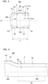
- FIG. 2 is a cross-sectional view of the railway axle 1 of this invention shown in FIG. 1 taken along a plane including the center axis C1 of the railway axle 1.
- FIG. 3 is an enlarged cross-sectional view of a region 200 shown in FIG. 2 .
- each of the fitting portions 2 (2A and 2D) includes a fitting portion hardened layer 2H formed in an outer layer, and a base metal portion BM disposed inward of the fitting portion hardened layer 2H.
- the fitting portion hardened layer 2H is formed in the outer layer ranging from the surface of the fitting portion 2 to a predetermined depth.
- the fitting portion hardened layer 2H may not be formed over the entire surface of the fitting portion 2.
- the fitting portion hardened layer 2H is formed at a portion in a region disposed closer to the outer end 2 OU in the direction of the center axis C1 of the railway axle 1 than a center position CE2 of the fitting portion 2, and at a portion in a region disposed closer to the inner end 2 IN in the direction of the center axis C1 of the railway axle 1 than the center position CE2 is.
- the fitting portion hardened layer 2H is not formed at a portion in a region including the center position CE2.
- the fitting portion hardened layer 2H may not be formed over the entire surface of the fitting portion 2, and may be formed in at least some regions, in the direction of the center axis C1, on the surface of the fitting portion 2. Further, the fitting portion hardened layer 2H may be formed over the entire surface of the fitting portion 2. The fitting portion hardened layer 2H will be described later.
- FIG. 4 is an enlarged cross-sectional view of a region 300 shown in FIG. 2 .
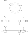
- FIG. 5 is a cross-sectional view taken along line segment II-II in FIG. 2 .
- the center parallel portion 3 also includes a center parallel portion hardened layer 3H formed in the outer layer of the center parallel portion 3, and the base metal portion BM disposed inward of the center parallel portion hardened layer 3H.
- the center parallel portion hardened layer 3H is formed in the outer layer ranging from the surface of the center parallel portion 3 to a predetermined depth.
- the center parallel portion hardened layer 3H is formed over the entire surface of the center parallel portion 3.
- the center parallel portion hardened layer 3H will be described later.
- each of the chemical composition of the base metal portion BM of the pair of fitting portions 2 and the chemical composition of the base metal portion BM of the center parallel portion 3 contains the following elements.
- a line segment connecting the surface of the railway axle 1 and the center axis C1 is defined as "radius R”.
- the chemical composition of the base metal portion BM means the chemical composition at the R/2 position of the fitting portion 2, and the R/2 position of the center parallel portion 3.
- % in relation to an element means mass% unless otherwise specified.
- Carbon (C) increases the hardness of steel.
- Performing induction hardening also causes C to increase the hardness of the hardened layer.
- C content is less than 0.30%, even when the content of other elements falls within the ranges given in this embodiment, the hardness of the base metal portion and the hardened layer decreases. Therefore, compressive residual stress in the fitting portion hardened layer 2H of the fitting portion 2 decreases. In this case, the fitting portion 2 of the railway axle 1 cannot obtain the fatigue limit.
- quench cracking may occur at the time of performing induction hardening.
- C content is set to 0.30 to 0.42%.
- the lower limit of C content is preferably set to 0.31%, more preferably set to 0.32%, furthermore preferably set to 0.33%, and still furthermore preferably set to 0.34%.
- the upper limit of C content is preferably set to 0.41%, and more preferably set to 0.40%.
- Si deoxidizes steel. Si also increases temper softening resistance of steel, and increases the fatigue limit of the center parallel portion 3. In the case where Si content is less than 0.10%, even when the content of other elements falls within the ranges given in this embodiment, these advantageous effects cannot be sufficiently obtained. Whereas in the case where Si content is more than 0.50%, even when the content of other elements falls within the ranges given in this embodiment, quench cracking may occur at the time of performing induction hardening. When Si content is more than 0.50%, there may be also a case where the center parallel portion 3 cannot obtain the fatigue limit. Accordingly, Si content is set to 0.10 to 0.50%.
- the lower limit of Si content is preferably set to 0.20%, more preferably set to 0.12%, more preferably set to 0.15%, more preferably set to 0.17%, more preferably set to 0.20%, more preferably set to 0.23%, and more preferably set to 0.25%.
- the upper limit of Si content is preferably set to 0.45%, more preferably set to 0.42%, more preferably set to 0.39%, more preferably set to 0.37%, more preferably set to 0.35%, and more preferably set to 0.33%.
- Manganese (Mn) increases hardenability of steel.
- Performing induction hardening causes Mn to increase the thickness of the fitting portion hardened layer 2H and the thickness of the center parallel portion hardened layer 3H.
- Mn content is less than 0.40%, even when the content of other elements falls within the ranges given in this embodiment, the center parallel portion hardened layer 3H may have an excessively small thickness. In this case, the center parallel portion 3 cannot obtain sufficient fatigue limit.
- Mn content is more than 1.20%, even when the content of other elements falls within the ranges given in this embodiment, the fitting portion hardened layer 2H formed by performing induction hardening may have an excessively large thickness.
- Mn content is set to 0.40 to 1.20%.
- the lower limit of Mn content is preferably set to 0.45%, more preferably set to 0.50%, more preferably set to 0.55%, more preferably set to 0.60%, more preferably set to 0.65%, and more preferably set to 0.70%.
- the upper limit of Mn content is preferably set to 1.10%, more preferably set to 1.05%, more preferably set to 1.00%, more preferably set to 0.95%, and more preferably set to 0.90%.
- Phosphorus (P) is an inevitable impurity.
- P content is more than 0%. P segregates in grain boundaries, thus decreasing the fatigue limit of steel.
- the upper limit of P content is preferably set to 0.018%, more preferably set to 0.016%, furthermore preferably set to 0.015%, and still furthermore preferably set to 0.014%. It is preferable that P content be as low as possible. However, an excessive reduction in P content significantly increases production costs. For this reason, in consideration of industrial production, the lower limit of P content is preferably set to 0.001%, and more preferably set to 0.002%.
- S Sulfur
- S is an inevitable impurity.
- S content is more than 0%.
- S is bonded to Mn, thus forming MnS.
- MnS decreases fatigue strength of steel.
- S content is set to 0.040% or less.
- the upper limit of S content is preferably set to 0.030%, more preferably set to 0.020%, furthermore preferably set to 0.015%, and still furthermore preferably set to 0.010%. It is preferable that S content be as low as possible.
- the lower limit of S content is preferably set to 0.001%, and more preferably set to 0.002%.
- N Nitrogen
- N content is more than 0%.
- N is bonded to Al or the like, thus forming fine nitride, and thus making the grain fine.
- N content is excessively high, coarse nitride is formed, thus decreasing the fatigue limit of steel.
- N content is set to 0.0200% or less.
- the upper limit of N content is preferably set to 0.0150%, more preferably set to 0.0120%, more preferably set to 0.0100%, more preferably set to 0.0090%, more preferably set to 0.0080%, and more preferably set to 0.0070%.
- the lower limit of N content for more effectively obtaining the above-mentioned advantageous effects is preferably set to 0.0010%, more preferably set to 0.0020%, and furthermore preferably set to 0.0030%.
- Oxygen (O) is an inevitable impurity. In other words, O content is more than 0%. There may be a case where O forms coarse oxide which may become a starting point of fatigue fracture. In the case where O content is more than 0.0040%, even when the content of other elements falls within the ranges given in this embodiment, the fatigue limit of the center parallel portion 3 decreases. Accordingly, O content is set to 0.0040% or less.
- the upper limit of O content is preferably set to 0.0030%, more preferably set to 0.0025%, furthermore preferably set to 0.0020%, and still furthermore preferably set to 0.0015%. It is preferable that O content be as low as possible. However, an excessive reduction in O content significantly increases production costs. For this reason, in consideration of industrial production, the lower limit of O content is preferably set to 0.0001%, more preferably set to 0.0002%, and furthermore preferably set to 0.0005%.
- Ca is an impurity. Ca may not be contained. In other words, Ca content may be set to 0%. Ca causes silicate inclusions (a group C specified in JIS G 0555(2003)) to agglomerate, thus decreasing the fatigue limit of steel. In the case where Ca content is more than 0.0010%, even when the content of other elements falls within the ranges given in this embodiment, the silicate inclusion becomes a starting point of fatigue fracture, so that the fatigue limit of the center parallel portion 3 decreases. Accordingly, Ca content is set to 0 to 0.0010%. The upper limit of Ca content is preferably set to 0.0006%, more preferably set to 0.0004%, and furthermore preferably set to 0.0003%.
- the balance of the chemical composition of the base metal portion BM of the fitting portion 2 and the center parallel portion 3 consists of Fe and impurities.
- impurities mean materials which are mixed into a steel material for the railway axle 1 from ore or scrap as a raw material, a production environment or the like in industrially producing the steel material for the railway axle 1, and which are allowed within a range where the impurities do not adversely affect the railway axle 1 of this invention.
- the chemical composition of the base metal portion BM of the fitting portion 2 and the center parallel portion 3 of the railway axle 1 according to this invention may further contain one or more elements selected from a group consisting of Cr, Mo, Cu, and Ni in lieu of a part of Fe. Any of these elements is an optional element, and increases strength of steel.
- Chromium (Cr) is an optional element, and may not be contained. In other words, Cr content may be set to 0%. When Cr is contained, Cr increases hardenability of steel. Performing induction hardening causes Cr to increase the hardness of the fitting portion hardened layer 2H and the center parallel portion hardened layer 3H. When even a small amount of Cr is contained, the above-mentioned advantageous effects can be obtained to some extent. However, in the case where Cr content is more than 0.30%, even when the content of other elements falls within the ranges given in this embodiment, the fitting portion hardened layer 2H formed by performing induction hardening may have an excessively large thickness.
- Cr content is set to 0 to 0.30%.
- the lower limit of Cr content is preferably set to more than 0%, more preferably set to 0.05%, more preferably set to 0.06%, more preferably set to 0.07%, more preferably set to 0.08%, more preferably set to 0.09%, and more preferably set to 0.10%.
- the upper limit of Cr content is preferably set to 0.27%, more preferably set to 0.25%, more preferably set to 0.23%, more preferably set to 0.21%, and more preferably set to 0.20%.
- Molybdenum (Mo) is an optional element, and may not be contained. In other words, Mo content may be set to 0%. When Mo is contained, Mo increases strength of steel. When even a small amount of Mo is contained, the above-mentioned advantageous effect can be obtained to some extent. However, in the case where Mo content is more than 0.10%, even when the content of other elements falls within the ranges given in this embodiment, the above-mentioned advantageous effect is saturated. Further, when Mo content is more than 0.10%, production costs excessively increase. Accordingly, Mo content is set to 0 to 0.10%. The lower limit of Mo content is preferably set to more than 0%, more preferably set to 0.01%, and more preferably set to 0.02%.
- the upper limit of Mo content is preferably set to 0.09%, more preferably set to 0.08%, more preferably set to less than 0.08%, more preferably set to 0.07%, more preferably set to 0.06%, more preferably set to 0.05%, and more preferably set to 0.04%.
- Copper (Cu) is an optional element, and may not be contained. In other words, Cu content may be set to 0%. In the case where Cu is contained, Cu increases strength of steel. When even a small amount of Cu is contained, such an advantageous effect can be obtained to some extent. However, in the case where Cu content is more than 0.30%, even when the content of other elements falls within the ranges given in this embodiment, hot workability of steel decreases. Accordingly, Cu content is set to 0 to 0.30%.
- the lower limit of Cu content is preferably set to more than 0%, more preferably set to 0.01%, and more preferably set to 0.02%.
- the upper limit of Cu content is preferably set to 0.25%, more preferably set to 0.20%, more preferably set to 0.15%, more preferably set to 0.10%, and more preferably set to 0.05%.
- Nickel (Ni) is an optional element, and may not be contained. In other words, Ni content may be set to 0%. In the case where Ni is contained, Ni increases strength of steel. When even a small amount of Ni is contained, such an advantageous effect can be obtained to some extent. However, in the case where Ni content is more than 0.30%, even when the content of other elements falls within the ranges given in this embodiment, the above-mentioned advantageous effect is saturated. Accordingly, Ni content is set to 0 to 0.30%.
- the lower limit of Ni content is preferably set to more than 0%, more preferably set to 0.01%, furthermore preferably set to 0.02%, and still furthermore preferably set to 0.04%.
- the upper limit of Ni content is preferably set to 0.25%, more preferably set to less than 0.20%, furthermore preferably set to 0.15%, and still furthermore preferably set to 0.10%.
- the chemical composition of the base metal portion BM of the railway axle according to th invention may further contain Al in lieu of a part of Fe.
- Aluminum (Al) is an optional element, and may not be contained. In other words, Al content may be set to 0%. In the case where Al is contained, Al deoxidizes steel. Further, Al is bonded to N, thus forming AlN, and thus making the grain fine. As a result, toughness of steel increases. When even a small amount of Al is contained, these advantageous effects can be obtained to some extent. However, in the case where Al content is more than 0.100%, even when the content of other elements falls within the ranges given in this embodiment, coarse oxide inclusions are formed, so that the fatigue limit of the railway axle 1 decreases. Accordingly, Al content is set to 0 to 0.100%.
- the lower limit of Al content is preferably set to more than 0%, more preferably set to 0.005%, more preferably set to 0.007%, more preferably set to 0.010%, more preferably set to 0.015%, and more preferably set to 0.020%.
- the upper limit of Al content is preferably set to 0.080%, more preferably set to 0.060%, more preferably set to 0.050%, more preferably set to 0.045%, and more preferably set to 0.040%.
- Al content means the content of acid soluble Al (sol. Al).
- the chemical composition of the base metal portion BM of the railway axle according to th invention may further contain one more elements selected from a group consisting of V, Ti, and Nb in lieu of a part of Fe. Any of these elements is an optional element, and increases strength of steel.
- Vanadium (V) is an optional element, and may not be contained. In other words, V content may be set to 0%. In the case where V is contained, V is bonded to N or C, thus forming V(C, N). In this case, V makes grain fine, thus increasing strength of steel. When even a small amount of V is contained, such an advantageous effect can be obtained to some extent. However, in the case where V content is more than 0.060%, even when the content of other elements falls within the ranges given in this embodiment, toughness of steel decreases. Accordingly, V content is set to 0 to 0.060%.
- the lower limit of V content is preferably set to more than 0%, more preferably set to 0.005%, furthermore preferably set to 0.008%, and still furthermore preferably set to 0.010%.
- the upper limit of V content is preferably set to 0.055%, more preferably set to 0.050%, furthermore preferably set to 0.045%, and still furthermore preferably set to 0.040%.
- Titanium (Ti) is an optional element, and may not be contained. In other words, Ti content may be set to 0%. In the case where Ti is contained, Ti is bonded to N, thus forming fine TiN. TiN increases strength of steel. TiN also makes grain fine, thus increasing the fatigue limit of steel. When even a small amount of Ti is contained, such an advantageous effect can be obtained to some extent. However, in the case where Ti content is more than 0.020%, even when the content of other elements falls within the ranges given in this embodiment, TiN precipitates become paths of cracks, thus decreasing toughness of steel. Accordingly, Ti content is set to 0 to 0.020%.
- the lower limit of Ti content is preferably set to more than 0%, more preferably set to 0.002%, and furthermore preferably set to 0.003%.
- the upper limit of Ti content is preferably set to 0.018%, more preferably set to 0.015%, more preferably set to 0.013%, more preferably set to 0.010%, and more preferably set to 0.007%.
- Niobium (Nb) is an optional element, and may not be contained. In other words, Nb content may be set to 0%. In the case where Nb is contained, Nb is bonded to N or C, thus forming Nb(C, N). In this case, Nb(C, N) makes grain fine, thus increasing strength and toughness of steel. When even a small amount of Nb is contained, such an advantageous effect can be obtained to some extent. However, in the case where Nb content is more than 0.030%, even when the content of other elements falls within the ranges given in this embodiment, carbide and/or carbonitride formed in steel may be coarsened. In this case, toughness of steel actually decreases. Accordingly, Nb content is set to 0 to 0.030%.
- the lower limit of Nb content is preferably set to more than 0%, more preferably set to 0.002%, furthermore preferably set to 0.003%, and still furthermore preferably set to 0.005%.
- the upper limit of Nb content is preferably set to 0.029%, more preferably set to 0.027%, furthermore preferably set to 0.025%, and still furthermore preferably set to 0.020%.
- the chemical composition of the base metal portion BM of the railway axle according to this invention may further contain B in lieu of a part of Fe.
- B Boron
- B content is an optional element, and may not be contained.
- B content may be set to 0%.
- B increases hardenability of steel.
- toughness of steel decreases.
- B content is set to 0 to 0.0050%.
- the lower limit of B content is preferably set to more than 0%, more preferably set to 0.0003%, furthermore preferably set to 0.0005%, and still furthermore preferably set to 0.0007%.
- the upper limit of B content is preferably set to 0.0040%, more preferably set to 0.0030%, and furthermore preferably set to 0.0020%.
- the microstructure of the base metal portion BM of the railway axle 1 according to this embodiment is mainly composed of ferrite structure and pearlite structure.
- "mainly composed of ferrite structure and pearlite structure” means that the total area fraction of ferrite and pearlite in the microstructure is 70% or more.
- the balance of the microstructure of the base metal portion BM of the railway axle 1 according to this embodiment is one or more kinds selected from a group consisting of martensite, bainite, and retained austenite, for example.
- martensite also includes tempered martensite.
- bainite also includes tempered bainite.
- the total of the area fraction of ferrite and the area fraction of pearlite in the microstructure may be obtained by the following method.
- Five samples for observing the microstructure are taken from R/2 position on a cross section perpendicular to the direction of the center axis C1 of the fitting portion 2 or the center parallel portion 3.
- the cross section perpendicular to the center axis C1 is used as an observation surface.
- the observation surface of each sample is polished to a mirror finished surface and, thereafter, is immersed into Nital etching reagent for approximately 10 seconds to develop the microstructure by etching.
- the etched observation surface is observed by an optical microscope.
- One field of view is set to 40000 ⁇ m 2 (magnification ⁇ 500), and each sample is observed in one field of view (that is, five samples are observed in five fields of view in total). Ferrite and pearlite are identified in each field of view based on the contrast. Based on the total area of the identified ferrite and pearlite and the area (40000 ⁇ m 2 ) of each field of view, the total area fraction of ferrite and pearlite in each field of view is obtained. The arithmetic average value of the total area fractions of ferrite and pearlite obtained for the respective fields of view is defined as the total area fraction (%) of ferrite and pearlite.
- the diameter of the fitting portion 2 of the railway axle 1 according to this embodiment is defined as D W (mm), and the diameter of the center parallel portion 3 of the railway axle 1 according to this embodiment is defined as D A (mm).
- D W /D A is set to 1.10 to 1.30, D W /D A being the ratio of the diameter D W of the fitting portion 2 to the diameter D A of the center parallel portion 3.
- the diameter ratio D W /D A is less than 1.10, and is close to 1.00.
- the reason is as follows.
- the diameter ratio D W /D A is large, hardening is not sufficiently performed on the center parallel portion 3 during induction hardening and, as a result, the hardened layer 3H of the center parallel portion 3 is formed with a small depth.
- the diameter ratio D W /D A is set close to 1.00, during induction hardening, a distance between the center parallel portion 3 and a high-frequency heating device becomes substantially equal to a distance between the fitting portion 2 and the high-frequency heating device.
- the diameter ratio D W /D A is set to less than 1.05, and is set as close to 1.00 as possible.
- the diameter ratio D W /D A is intentionally set to a large value. Specifically, the diameter ratio D W /D A is set to 1.10 or more. In this case, as described above, the fretting fatigue limit of the fitting portion 2 further increases. Further, the weight of the railway axle 1 can be reduced. However, when the diameter ratio D W /D A is excessively large, the fatigue limit of the center parallel portion 3 may decrease. Accordingly, in the railway axle 1 according to the invention, the diameter ratio D W /D A is set to 1.10 to 1.30.
- the lower limit of the diameter ratio D W /D A is preferably set to 1.11, more preferably set to 1.12, furthermore preferably set to 1.13, and still furthermore preferably set to 1.14.
- the upper limit of the diameter ratio D W /D A is preferably set to 1.25, more preferably set to 1.22, more preferably set to 1.20, more preferably set to 1.19, and more preferably set to 1.18.
- the depth Cw of the fitting portion hardened layer 2H at a position 5 mm away from the inner end 2 IN toward the outer end 2 OU of the fitting portion 2 in the direction of the center axis is 2.5 mm to 0.10 ⁇ D W (mm).
- depth of hardened layer means an effective case depth specified in JIS G 0559(2008).
- the effective case depth of the fitting portion hardened layer 2H in this invention means a distance (mm) in the radial direction from the surface of the fitting portion 2 to the position of limit hardness.
- the effective case depth of the center parallel portion hardened layer 3H means a distance (mm) in the radial direction from the surface of the center parallel portion 3 to the position of limit hardness.
- the limit hardness of an effective case is defined, based on JIS G 0559(2008), as 400 HV in terms of Vickers hardness specified in a material with a component where C content is 0.33% or more and less than 0.43%. Accordingly, in this invention, limit hardness is 400 HV in terms of Vickers hardness.
- the fitting portion hardened layer 2H is formed in the fitting portion 2 by performing induction hardening.
- compressive residual stress is generated in the fitting portion 2.
- compressive residual stress generated in the fitting portion 2 suppresses extension of cracks caused by fretting. Therefore, fretting fatigue can be suppressed by appropriately adjusting compressive residual stress to be generated in the fitting portion 2.
- the fitting portion hardened layer 2H may not be formed over the entire surface of the fitting portion 2. It is preferable that, on the surface of the fitting portion, the fitting portion hardened layer 2H be formed in each of regions on both sides of the fitting portion, each region having a length of at least 1/3 of the length of the fitting portion in the axial direction.
- the fitting portion hardened layer 2H is formed within a range of at least L 2 /3 from the outer end 2 OU toward the center position CE2 and within a range of at least L 2 /3 from the inner end 2 IN toward the center position CE2.
- the depth Cw of the fitting portion hardened layer 2H means a depth at a position 5 mm away from the inner end 2 IN toward the outer end 2ou of the fitting portion 2 in the direction of the center axis C1 of the railway axle 1 (that is, in the longitudinal direction of the railway axle 1) (see FIG. 3 ).
- the depth Cw of the fitting portion hardened layer 2H is less than 2.5 mm, the fitting portion 2 has excessively small compressive residual stress.
- the depth Cw of the fitting portion hardened layer 2H is more than 0.10 ⁇ D W (mm)
- compressive residual stress generated in the fitting portion 2 actually reduces.
- the depth Cw of the fitting portion hardened layer 2H at a position 5 mm away from the inner end 2 IN toward the outer end 2 OU in the direction of the center axis is set to 2.5 mm to 0.10 ⁇ D W (mm).
- the lower limit of the depth Cw of the fitting portion hardened layer 2H is preferably set to 2.8 mm, more preferably set to 3.0 mm, furthermore preferably set to 3.5 mm, and still furthermore preferably set to 4.0 mm.
- the upper limit of the depth Cw of the fitting portion hardened layer 2H is preferably set to 0.09 ⁇ D W (mm), more preferably set to 0.085 ⁇ D W (mm), furthermore preferably set to 0.08 ⁇ D W (mm), and still furthermore preferably set to 0.075 ⁇ D W (mm).
- C W /C A is set to 0.34 to 0.93, C W /C A being the ratio of the depth Cw of the fitting portion hardened layer 2H to the depth C A of the hardened layer 3H of the center parallel portion.
- the ratio of the depth Cw of the fitting portion hardened layer 2H to the depth C A of the center parallel portion hardened layer 3H is defined as "case depth ratio C W /C A ".
- the conventional railway axle has the case depth ratio C W /C A of 1.0 or more.
- the case depth ratio C W /C A is set to 0.34 to 0.93.
- the center parallel portion hardened layer 3H is formed with a depth larger than the depth of the fitting portion hardened layer 2H.
- the starting point of fracture caused by fatigue in the fitting portion 2 is on the surface, whereas the starting point of fracture caused by fatigue in the center parallel portion 3 is at a position inward of the surface.
- the depth Cw of the fitting portion hardened layer 2H is set to 2.5 mm to 0.10 ⁇ D W (mm), and C W /C A is set to 0.34 to 0.93
- the fitting portion hardened layer 2H having a sufficient depth and sufficient compressive residual stress is provided as the outer layer of the fitting portion 2.
- the outer layer of the center parallel portion 3 can also obtain the sufficient depth C A of the center parallel portion hardened layer 3H.
- the fitting portion 2 can obtain the excellent fatigue limit (fretting fatigue limit), and the center parallel portion 3 can obtain the excellent fatigue limit (the bending fatigue limit).
- the lower limit of the case depth ratio C W /C A is preferably set to 0.40, more preferably set to 0.50, more preferably set to 0.55, more preferably set to 0.60, and more preferably set to 0.62.
- the upper limit of the case depth ratio C W /C A between the fitting portion 2 and the center parallel portion 3 is preferably set to 0.91, more preferably set to 0.89, furthermore preferably set to 0.88, and still furthermore preferably set to 0.87.
- the depth Cw of the fitting portion hardened layer 2H, the depth C A of the center parallel portion hardened layer 3H, and the case depth ratio C W /C A may be decided by a method in accordance with JIS G 0559(2008).
- the depth Cw of the fitting portion hardened layer 2H is defined as follows. Specifically, referring to FIGS. 1 to 3 , one point is specified at a position, in the railway axle 1, 5 mm away from the inner end 2 IN of the fitting portion 2A or 2D toward the outer end 2 OU in the direction of the center axis (longitudinal direction).
- the railway axle 1 is cut at the specified position along a line perpendicular to the center axis C1, thus forming a cut surface.
- a sample is taken which has this cut surface, and which includes the outer layer portion of the fitting portion 2.
- the above-mentioned cut surface is assumed as a measurement surface.
- a Vickers hardness test is performed on the above-mentioned measurement surface. Specifically, the Vickers hardness test in accordance with JIS Z 2244(2009) is performed on the measurement surface in the radial direction (depth direction) of the railway axle 1 from the surface of the fitting portion 2 with a load of 2.9 N and a pitch of 0.1 mm so as to measure Vickers hardness (HV). Based on a hardness transition curve obtained by the Vickers hardness test, a distance from the surface of the railway axle 1 to limit hardness is obtained. As described above, the above-mentioned limit hardness means 400 HV in terms of Vickers hardness. In other words, a depth from the surface where Vickers hardness is 400 HV or more (limit hardness or more) is measured. A distance from the surface of the fitting portion 2 to limit hardness is defined as Cw (mm).
- the depth Cw of the fitting portion hardened layer 2H at a position 5 mm away from the inner end 2 IN toward the outer end 2 OU of the fitting portion 2 in the direction of the center axis is 2.5 mm to 0.10 ⁇ D W (mm).
- the depth C A of the center parallel portion hardened layer 3H is defined as follows.
- the center parallel portion 3 of the railway axle 1 is specified.
- the center parallel portion 3 is a column of the railway axle 1 which is disposed between the pair of fitting portions 2, and which has a diameter smaller than the diameter D W of the fitting portion 2.
- a column having the largest length in the direction of the center axis is defined as the center parallel portion 3.
- the specified center parallel portion 3 is divided into four sections 3A to 3D equidistantly in the direction of the center axis C1. Specifically, in the direction of the center axis C1 of the railway axle 1, the specified center parallel portion 3 is divided into the section 3A, the section 3B, the section 3C, and the section 3D, the section 3A and the section 3B being disposed on the fitting portion 2A side of the center position of the center parallel portion 3, the section 3C and the section 3D being disposed on the fitting portion 2D side of the center position of the center parallel portion 3.
- the depth of the center parallel portion hardened layer 3H of each of the sections 3A to 3D is measured by the following method.
- the depth C AA of the center parallel portion hardened layer 3H of the section 3A and the depth C AD of the center parallel portion hardened layer 3H of the section 3D are defined as follows. Referring to FIG. 2 and FIG. 4 , the depth C AA of the center parallel portion hardened layer 3H of the section 3A will be described. As shown in FIG. 4 , the section 3A is cut along a plane including the direction of the center axis C1 of the railway axle 1 and the radial direction of the center parallel portion 3. This cut surface is assumed as a measurement surface.
- the measurement surface is polished to a mirror finished surface and, thereafter, is immersed into Nital etching reagent for approximately 10 seconds to develop the microstructure by etching.
- the etched observation surface is visually checked to identify a position where the center parallel portion hardened layer 3H has the smallest thickness on the measurement surface.
- a distance from the surface of the railway axle 1 to limit hardness is obtained by substantially the same method as used for obtaining the depth Cw of the fitting portion hardened layer 2H.
- the obtained distance to the limit hardness is defined as the depth C AA (mm) of the center parallel portion hardened layer 3H.
- the depth C AD (mm) of the center parallel portion hardened layer 3H of the section 3D is also defined by the same method as used for obtaining the depth C AA (mm) of the center parallel portion hardened layer 3H of the section 3A.
- the depth C AB of the center parallel portion hardened layer 3H of the section 3B and the depth C AC of the center parallel portion hardened layer 3H of the section 3C are defined as follows. Specifically, referring to FIG. 5 , the depth C AB of the center parallel portion hardened layer 3H of the section 3B will be described.
- the section 3B of the railway axle 1 is cut, at an arbitrary point, along a line perpendicular to the center axis of the railway axle 1 (see FIG. 5 ).
- the cut surface is polished to a mirror finished surface and, thereafter, is immersed into Nital etching reagent for approximately 10 seconds to develop the microstructure by etching.
- the etched observation surface is visually checked to identify a position where the center parallel portion hardened layer 3H has the smallest thickness on the cut surface.
- a distance from the surface of the railway axle 1 to limit hardness is obtained by substantially the same method as used for obtaining the depth Cw of the fitting portion hardened layer 2H.
- the obtained distance to the limit hardness is defined as the depth C AB (mm) of the center parallel portion hardened layer 3H.
- the depth C AC (mm) of the center parallel portion hardened layer 3H of the section 3C is also defined by substantially the same method as used for obtaining the depth C AB of the center parallel portion hardened layer 3H of the section 3B.
- the sections 3A and 3B are disposed on the fitting portion 2A side of the center position of the center parallel portion 3 in the direction of the center axis C1 of the railway axle 1, and C AA of the section 3A and C AB of the section 3B are obtained.
- C AA or C AB whichever has the smaller value is defined as a depth C A1 (mm) of the center parallel portion hardened layer 3H which corresponds to the fitting portion 2A.
- the ratio of the depth Cw (mm) of the fitting portion hardened layer 2H of the fitting portion 2A to the depth C A1 (mm) of the center parallel portion hardened layer 3H is defined as a case depth ratio C W /C A1 .
- the sections 3C and 3D are disposed on the fitting portion 2D side of the center position of the center parallel portion 3 in the direction of the center axis C1 of the railway axle 1, and C AC of the section 3C and C AD of the section 3D are obtained.
- C AC or C AD whichever has the smaller value is defined as a depth C A2 (mm) of the center parallel portion hardened layer 3H which corresponds to the fitting portion 2D.
- the ratio of the depth Cw (mm) of the fitting portion hardened layer 2H of the fitting portion 2D to the depth C A2 (mm) of the center parallel portion hardened layer 3H is defined as a case depth ratio C W /C A2 .
- the case depth ratios C W /C A1 and C W /C A2 are also collectively referred to as "C W /C A ".
- C W /C A which is the ratio of the depth Cw of the fitting portion hardened layer 2H of the fitting portion 2 to the depth C A of the hardened layer 3H of the center parallel portion, is set to 0.34 to 0.93.
- the case depth ratio C WA /C A1 which is the ratio of the depth C WA (mm) of the fitting portion hardened layer 2H of the fitting portion 2A to the depth C A1 (mm) of the center parallel portion hardened layer 3H
- the case depth ratio C WD /C A2 which is the ratio of the depth C WD (mm) of the fitting portion hardened layer 2H of the fitting portion 2D to the depth C A2 (mm) of the center parallel portion hardened layer 3H, is set to 0.34 to 0.93.
- the maximum hardness of the fitting portion hardened layer 2H is 400 HV or more in terms of Vickers hardness.
- the fraction of martensite generated during induction hardening is high. Therefore, large compressive residual stress is generated in the fitting portion hardened layer 2H. As a result, propagation of fretting fatigue crack in the fitting portion 2 can be suppressed, so that the railway axle 1 can obtain the higher fatigue limit.
- the maximum hardness of the center parallel portion hardened layer 3H of the center parallel portion 3 is 400 HV or more in terms of Vickers hardness.
- the fraction of martensite generated during induction hardening is high. Therefore, large compressive residual stress is generated in the center parallel portion hardened layer 3H.
- the respective elements in the chemical composition of the base metal portion of the fitting portion 2 and the center parallel portion 3 fall within the above-mentioned ranges, the diameter ratio D W /D A is set to 1.10 to 1.30, the depth Cw of the fitting portion hardened layer 2H of each of the respective fitting portions 2 is set to 2.5 mm to 0.10 ⁇ D W mm, and the case depth ratio C W /C A is set to 0.34 to 0.93. Therefore, compared with the conventional railway axle, the weight can be reduced due to an increase in the diameter ratio D W /D A , and both the fitting portions 2 and the center parallel portion 3 can obtain the excellent fatigue limit.
- the hardened layer formed by rolling has Vickers hardness of less than 300 HV, that is, has hardness much lower than the hardness of the fitting portion hardened layer 2H and the center parallel portion hardened layer 3H in this embodiment.
- the railway axle 1 of this invention is not limited to the configuration shown in FIG. 1 .
- one or a plurality of fitting portions 6 may be disposed between the pair of railway wheel fitting portions 2.
- a gear or the like of a power source not shown in the drawing may be press-fitted on each fitting portion 6, or a brake disc may be press-fitted on each fitting portion 6.
- a base material other than the railway wheel is press-fitted on each fitting portion 6.
- a column having the largest length in the direction of the center axis is defined as the center parallel portion 3.
- the hardened layer may also be formed in the fitting portion 6 by performing induction hardening. In this case, fretting with the gear, the disc brake or the like is suppressed, so that the fatigue limit of the railway axle 1 further increases.
- Molten steel having the above-mentioned chemical composition is produced.
- An ingot is produced using the molten steel.
- Hot forging is performed on the ingot to produce a crude product having the shape of an axle. It is sufficient that the heating temperature at which the ingot is heated during hot forging falls within a well-known temperature range.
- the heating temperature may be set to 1000 to 1300°C, for example. Quenching and tempering, or a normalizing treatment is performed on the produced crude product.
- a quenching temperature is set to the A c3 transformation point or more during quenching.
- the crude product is held at the quenching temperature and, thereafter, is rapidly cooled by water cooling or oil cooling.
- a tempering temperature is set to the A c1 transformation point or less during the tempering.
- the crude product is held at the tempering temperature and, thereafter, is allowed to cool.
- the normalizing treatment is performed, the crude product is held at a heat treatment temperature which is higher than the A c1 transformation point and, thereafter, is allowed to cool.
- the tempering may be performed after the normalizing treatment.
- the total area fraction of ferrite and pearlite is 70% or more in the microstructure of the base metal portion BM of the railway axle 1 of this embodiment.
- the balance of the microstructure of the base metal portion BM of the railway axle 1 according to this embodiment may be one or more kinds selected from a group consisting of martensite, bainite, and retained austenite, for example.
- the induction hardening treatment is performed on the crude product.
- the induction hardening treatment will be described in detail.
- the outer layer portion of the crude product is heated to a temperature higher than the A c3 transformation point by high-frequency heating and, thereafter, is rapidly cooled.
- a method for rapid cooling may be water cooling, for example.
- the diameter ratio D W /D A which is the ratio of the diameter D W of the fitting portion 2 to the diameter D A of the center parallel portion 3, is set to 1.10 to 1.30.
- the center parallel portion 3 has a smaller diameter than the fitting portion 2.
- the depth C A of the center parallel portion hardened layer 3H is larger than the depth Cw of the fitting portion hardened layer 2H.
- C W /C A which is the ratio of the depth Cw of the fitting portion hardened layer 2H of the fitting portion 2 to the depth C A of the center parallel portion hardened layer 3H, is set to 0.34 to 0.93.
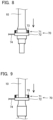
- FIG. 8 is a view showing one example of an induction hardening apparatus used in the method for producing the railway axle 1 of this embodiment.
- an induction hardening apparatus 70 includes a high-frequency heating device 71 having an annular shape and a water cooling device 72 having an annular shape.
- the high-frequency heating device 71 and the water cooling device 72 are coaxially disposed.
- the high-frequency heating device 71 is disposed on the water cooling device 72.
- FIG. 8 shows the longitudinal cross section (a cross section including the center axis of the high-frequency heating device 71) of the high-frequency heating device 71.
- a high-frequency heating coil 73 having an annular shape is disposed on the high-frequency heating device 71.
- Cooling fluid injection nozzles not shown in the drawing are disposed in the water cooling device 72.
- a cooling fluid is supplied to the water cooling device 72 through a supply pipe 74.
- the water cooling device 72 injects the cooling fluid toward a crude product 10 of the railway axle from the cooling fluid injection nozzles so as to rapidly cool (quench) the crude product 10.
- the crude product 10 of the railway axle 1 (the railway axle 1 on which the induction hardening treatment is not performed) is inserted into the induction hardening apparatus 70.
- the crude product 10 is moved downward from above relative to the induction hardening apparatus 70.
- a portion of the crude product 10 is heated to the A c3 transformation point or more by the high-frequency heating device 71 and, such a portion is rapidly cooled thereafter by the water cooling device 72, thus forming a hardened layer.
- the fitting portion hardened layer 2H is formed in the fitting portion 2 by performing quenching, as shown in FIG. 8 , the fitting portion 2 of the crude product 10 is heated to the A c3 transformation point or more. Then, the crude product 10 is moved downward from above relative to the induction hardening apparatus 70 so as to rapidly cool the heated fitting portion 2 with the water cooling device 72 disposed below the high-frequency heating device 71.
- the cooling fluid injection nozzles of the water cooling device 72 inject cooling fluid toward the fitting portion 2.
- the cooling fluid may be water, for example.
- the fitting portion hardened layer 2H is formed by the above-mentioned steps.
- the center parallel portion hardened layer 3H is formed in the center parallel portion 3 by performing quenching
- the center parallel portion 3 of the crude product 10 is heated to the A c3 transformation point or more.
- the crude product 10 is moved downward from above relative to the induction hardening apparatus 70 so as to rapidly cool the heated center parallel portion 3 with the water cooling device 72 disposed below the high-frequency heating device 71.
- the cooling fluid injection nozzles of the water cooling device 72 inject cooling fluid toward the fitting portion 2.
- the center parallel portion hardened layer 3H is formed by the above-mentioned steps.
- the diameter ratio D W /D A of the railway axle 1 is set to 1.10 to 1.30. Therefore, as shown in FIG. 8 and FIG. 9 , a distance between the fitting portion 2 and the high-frequency heating coil 73 (see FIG. 8 ) during high-frequency heating is smaller than a distance between the center parallel portion 3 and the high-frequency heating coil 73 during high-frequency heating (see FIG. 9 ).
- the fitting portion hardened layer 2H is formed with a larger depth than the center parallel portion hardened layer 3H.
- C W /C A becomes 1.00 or more.
- the output from the high-frequency heating device 71 in the case of performing the high-frequency heating on the center parallel portion 3 is set higher than the output from the high-frequency heating device 71 in the case of performing the high-frequency heating on the fitting portion 2 so as to adjust the depth Cw of the fitting portion hardened layer 2H and the depth C A of the center parallel portion hardened layer 3H.
- frequency of an AC current of the high-frequency heating device 71 is set to 3 to 5 kHz. In this case, heating can be performed within a range having a large depth from the surface of the crude product 10.
- an adjustment is performed such that the output from the high-frequency heating device 71 during the high-frequency heating performed on the center parallel portion 3 is set to 1.1 to 1.2 times or more as large as the output from the high-frequency heating device 71 during the high-frequency heating performed on the fitting portion 2.
- the frequency of the high-frequency heating device 71, and the ratio of the output from the high-frequency heating device 71 during the high-frequency heating performed on the center parallel portion 3 to the output from the high-frequency heating device 71 during the high-frequency heating performed on the fitting portion 2 may be suitably adjusted depending on the size of the railway axle 1 and the diameter ratio D W /D A .
- the tempering may be performed after the induction hardening treatment is performed.
- the tempering is an optional treatment.
- the tempering temperature is set to 150 to 250°C, and a holding time at the tempering temperature is set to 30 to 150 minutes.
- One example of the tempering is such that the railway axle is heated to near 200°C, for example, and is held for approximately 120 minutes. After the railway axle is held, the railway axle is cooled with air.
- Final mechanical processing may be performed, when necessary, on the crude product 10 on which induction hardening is performed.
- the mechanical processing is an optional processing step.
- the mechanical processing lathe turning and polishing
- the railway axle 1 according to this embodiment can be produced by the above-mentioned steps.
- the above-mentioned method for producing the railway axle 1 is one example of the method for producing the railway axle 1 of this invention. Accordingly, the method for producing the railway axle 1 of this invention is not particularly limited to the above-mentioned production method provided that it is possible to produce the railway axle 1 of this embodiment where the respective elements in the chemical composition of the base metal portion of the fitting portion 2 and the center parallel portion 3 fall within the above-mentioned ranges, the diameter ratio D W /D A is 1.10 to 1.30, the depth Cw of the fitting portion hardened layer 2H of each of the respective fitting portions 2 is 2.5 mm to 0.10 ⁇ D W mm, and the case depth ratio C W /C A is 0.34 to 0.93.
- Molten steels having chemical compositions shown in Table 1 were produced.
- Symbol “-” in Table 1 means that the content of the corresponding element is at a level of impurity.
- symbol “-” in each of Cr, Mo, Cu, Ni, and V contents means that the content of each element is less than 0.01%.
- symbol “-” in Al content means that Al content is less than 0.002%.
- Symbol “-” in each of Ti and Nb contents means that the content of each element is less than 0.001%.
- Symbol “- " in each of B and Ca contents means that the content of each element is less than 0.0001%.
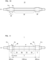
- Ingots were produced from molten steels of steel Nos. 1 to 22. Each ingot was heated to 1250°C and, thereafter, was subjected to hot forging to produce a crude product 10 having the shape of an axle shown in FIG. 10 .
- the crude product 10 included a pair of fitting portions 20, and a center parallel portion 30 disposed between the pair of fitting portions 20.
- an induction hardening treatment was performed on the crude product 10.
- the induction hardening treatment was performed on a hatched region of the crude product 10 shown in FIG. 10 .
- the fitting portion hardened layer 2H was formed within a range of at least L 2 /3 from the outer end 2 OU toward the center position CE2 and within a range of at least L 2 /3 from the inner end 2 IN toward the center position CE2.
- the depths of the respective hardened layer (the fitting portion hardened layer 2H, the center parallel portion hardened layer 3H) of the crude product 10 of each test No. were adjusted by adjusting an output from the high-frequency heating device 71 in the induction hardening apparatus 70 shown in FIG. 8 and FIG. 9 .
- the quenching temperature during the induction hardening was the A c3 transformation point or more of steel of each test No.
- the tempering was performed on the crude product 10. During the tempering, the entire crude product 10 of each test No. was held at 200°C for 120 minutes. After the crude product 10 was held, the crude product 10 was cooled with air until the crude product 10 has a normal temperature.
- FIG. 11 is a side view of the railway axle of this example.
- the railway axle 1 of each test No. includes the pair of fitting portions 2 and the center parallel portion 3.
- Each fitting portion 2 has a width of 200 mm.
- each fitting portion 2 has a diameter D W of 150 mm.
- each fitting portion 2 has a diameter D W of 112 mm.
- a distance between the inner ends 2 IN of the fitting portions 2 was 1330 mm.
- the railway axles 1 were produced by the above-mentioned production steps.
- the diameters D W of the fitting portions 2, the diameters D A of the center parallel portions 3, and the diameter ratios D W /D A of the railway axles 1 of respective test Nos. are shown in Table 2.
- FIG. 12 is a schematic view of a fatigue testing device for the railway axle 1 of this example.
- a jig 200 which corresponds to a wheel was press fitted on the fitting portion 2A on one side of the railway axle 1 of each test No.
- the jig 200 which corresponds to the wheel was fixed.
- the railway axle 1 was brought into a cantilever state.
- a plane bending fatigue test which repeatedly applies a load in a direction perpendicular to the direction of the center axis C1 of the railway axle 1 was performed.
- An electro-hydraulic servo fatigue tester load capacity 500 kN
- SAGINOMIYA SEISAKUSHO, INC. was used as a tester.
- Test conditions were such that an alternating load with a stress ratio of -1 was adopted, and frequency was 1 to 3 Hz.
- the upper limit of the number of repetitions was set to 5 ⁇ 10 6 times, and the test was performed until the railway axle 1 was broken off. In the case where the railway axle 1 was not broken off by 5 ⁇ 10 6 times, the test was terminated at such a point, and the railway axle 1 was determined as unbroken.
- the maximum value of a test stress at which the railway axle 1 is not broken off by 5 ⁇ 10 6 times is assumed as F M .
- the minimum value of a test stress at which the railway axle 1 is broken off at F M or more before the number of repetitions reaches 5 ⁇ 10 6 times is assumed as F B .
- test stress for the fitting portion corresponds to a nominal stress amplitude at the inner end 2 IN
- test stress for the center parallel portion corresponds to a surface stress amplitude at a break position.
- the railway axle 1 of each test No. was evaluated, based on the above-mentioned definition and evaluation method, with respect to the fatigue limit of the fitting portion 2D and the fatigue limit of the center parallel portion 3. Further, the fatigue limit of the fitting portion was obtained as a fatigue limit ratio using test No. 1 as the reference. The fatigue limit of the center parallel portion was obtained as a fatigue limit ratio using test No. 2 as the reference. The obtained fatigue limit ratios of respective test Nos. are shown in Table 2. When either one of the fitting portion or the center parallel portion was broken off, the test was terminated. Therefore, when only one of either the fitting portion or the center parallel portion was broken off, the other of either the fitting portion or the center parallel portion which was not broken off was determined as unbroken (symbol "-" in Table 2).
- the depth Cw of the fitting portion hardened layer of the fitting portion 2A was obtained by the above-mentioned method with reference to FIG. 11 , a wheel being press-fitted on the fitting portion 2A of the railway axle 1.
- a position P W 5 mm away from the inner end 2 IN toward the outer end 2 OU of the fitting portion 2A in the direction of the center axis (longitudinal direction) was specified.
- the railway axle 1 was cut at the position P W along a line perpendicular to the center axis C1 of the railway axle 1 to form a cut surface. A sample was taken which has such a cut surface and the outer layer portion of the fitting portion 2.
- the Vickers hardness test was performed on the above-mentioned cut surface. Specifically, Vickers hardness test in accordance with JIS Z 2244(2009) was performed on the cut surface with a load of 2.9 N and a pitch of 0.1 mm in the radial direction (depth direction) of the railway axle 1 from the surface of the fitting portion 2 so as to measure Vickers hardness (HV). Based on a hardness transition curve obtained by the Vickers hardness test, a distance from the surface of the railway axle 1 to limit hardness (400 HV) was obtained. The obtained distance was defined as a fitting portion case depth Cw. The obtained fitting portion case depths Cw are shown in Table 2.
- the depth Cw of the fitting portion hardened layer of the fitting portion 2D was obtained by substantially the same method as used for obtaining the depth Cw of the fitting portion hardened layer of the fitting portion 2A.
- the case depth Cw of the fitting portion 2A and the case depth Cw of the fitting portion 2D had the same value.
- the center parallel portion 3 of the railway axle 1 of each test No. was divided into four sections 3A to 3D equidistantly in the direction of the center axis C1.
- the depth C AA of the center parallel portion hardened layer 3H in the section 3A was obtained by the following method. Referring to FIG. 4 , the section 3A was cut along a plane including the direction of the center axis C1 of the railway axle 1 and the radial direction of the center parallel portion 3.
- the cut surface was polished to a mirror finished surface and, thereafter, was immersed into Nital etching reagent for approximately 10 seconds to develop the microstructure by etching.
- the etched cut surface was visually checked to identify a position where the center parallel portion hardened layer 3H has the smallest thickness on the cut surface.
- a distance from the surface of the railway axle 1 to limit hardness was obtained by the same method as used for obtaining the depth Cw of the fitting portion hardened layer 2H.
- the obtained distance to the limit hardness was defined as the depth C AA (mm) of the center parallel portion hardened layer 3H.
- the depth C AB of the center parallel portion hardened layer 3H in the section 3B was obtained by the following method.
- the section 3B of the railway axle 1 was cut, at an arbitrary point, along a line perpendicular to the center axis of the railway axle 1 (see FIG. 5 ).
- the cut surface was polished to a mirror finished surface and, thereafter, was immersed into Nital etching reagent for approximately 10 seconds to develop the microstructure by etching.
- the etched observation surface was visually checked to identify a position where the center parallel portion hardened layer 3H has the smallest thickness on the cut surface.
- a distance from the surface of the railway axle 1 to limit hardness was obtained by the same method as used for obtaining the depth Cw of the fitting portion hardened layer 2H.
- the obtained distance to the limit hardness was defined as the depth C AB (mm) of the center parallel portion hardened layer 3H.
- C AA and C AB obtained by the above-mentioned method, either C AA or C AB whichever has the smaller value was defined as the depth C A1 (mm) of the center parallel portion hardened layer 3H which corresponds to the fitting portion 2A.
- Ferrite and pearlite were identified in each field of view based on the contrast. Based on the total area of ferrite and pearlite in each field of view and the area (40000 ⁇ m 2 ) of each field of view, the total area fraction of ferrite and pearlite in each field of view was obtained. The arithmetic average value of the total area fractions of ferrite and pearlite obtained in the respective fields of view was defined as the total area fraction (%) of ferrite and pearlite.
- the total area fraction of ferrite and pearlite was 70% or more in the microstructure of the base metal portion BM.
- test No. 4 had an excessively small diameter ratio D W /D A .
- the fitting portion fatigue limit ratio was less than 1.00. In other words, test No. 4 did not obtain the excellent fatigue limit.
- Test No. 5 had an excessively large diameter ratio D W /D A . As a result, the center parallel portion fatigue limit ratio was less than 1.00. In other words, test No. 5 did not obtain the excellent fatigue limit.
- Test No. 6 had an excessively large case depth ratio C W /C A . As a result, the center parallel portion fatigue limit ratio was less than 1.00. In other words, test No. 6 did not obtain the excellent fatigue limit.
- Test No. 7 had an excessively small case depth ratio C W /C A . As a result, the center parallel portion fatigue limit ratio was less than 1.00. In other words, test No. 7 did not obtain the excellent fatigue limit.
- Test No. 8 had an excessively large depth Cw (mm) of the fitting portion hardened layer. As a result, the fitting portion fatigue limit ratio was less than 1.00. In other words, test No. 8 did not obtain the excellent fatigue limit.
- Test No. 21 had excessively low C content. As a result, the fitting portion fatigue limit ratio was less than 1.00. In other words, test No. 21 did not obtain the excellent fatigue limit.
- Test No. 25 had excessively low Mn content. As a result, the center parallel portion fatigue limit ratio was less than 1.00. In other words, test No. 25 did not obtain the excellent fatigue limit.
- Test No. 26 had excessively high Mn content. As a result, the fitting portion fatigue limit ratio was less than 1.00. In other words, test No. 26 did not obtain the excellent fatigue limit.
- Test No. 27 had excessively high Cr content. As a result, the fitting portion fatigue limit ratio was less than 1.00. In other words, test No. 27 did not obtain the excellent fatigue limit.
- Test No. 28 had excessively high P content. As a result, the center parallel portion fatigue limit ratio was less than 1.00. In other words, test No. 28 did not obtain the excellent fatigue limit.
- Test No. 29 had excessively high S content. As a result, the center parallel portion fatigue limit ratio was less than 1.00. In other words, test No. 29 did not obtain the excellent fatigue limit.
Landscapes
- Chemical & Material Sciences (AREA)
- Engineering & Computer Science (AREA)
- Mechanical Engineering (AREA)
- Materials Engineering (AREA)
- Metallurgy (AREA)
- Organic Chemistry (AREA)
- Physics & Mathematics (AREA)
- Thermal Sciences (AREA)
- Crystallography & Structural Chemistry (AREA)
- Heat Treatment Of Articles (AREA)
Description
- The present invention relates to an axle, and more particularly to a railway axle used for a railway vehicle.
- A railway wheel is press-fitted on each fitting portion of a railway axle. During the use, the railway axle supports the weight of a railway vehicle.
Specifically, interference is provided to each fitting portion of the railway axle to make a hole diameter of a boss portion of the railway wheel slightly smaller than the diameter of the fitting portion of the railway axle. The railway axle further receives a force in the horizontal direction due to a contact between the railway wheel and a rail each time the railway vehicle passes a curved rail (passes a curve). In other words, when the railway vehicle passes a curve, the railway axle repeatedly receives rotating bending stress each time the railway wheel turns one time. The amplitude of such bending stress increases when the railway vehicle passes the curve. - As described above, the railway axle includes the fitting portion on which the railway wheel is press-fitted, and the fitting portion has a contact interfacial pressure against the hole of the boss portion of the railway wheel. Therefore, slight slippage may repeatedly occur at the fitting portion of the railway axle due to a contact between the fitting portion and the railway wheel. Hereinafter, slight slippage which occurs due to a contact between the fitting portion of the railway axle and the railway wheel is referred to as fretting. It is known that the fitting portion of the railway axle may receive damage due to fretting (hereinafter also referred to as "fretting fatigue").
- To suppress such fretting fatigue, induction hardening may be performed on the above-mentioned fitting portion of the railway axle. In the outer layer of the fitting portion, hardness increases in a region on which induction hardening is performed. In the outer layer of the fitting portion, the region where hardness is increased by performing induction hardening as described above is referred to as "hardened layer". Compressive residual stress is generated in the hardened layer. The compressive residual stress generated due to the formation of the hardened layer suppresses extension of cracks caused by fretting. In other words, the hardened layer of the railway axle formed by performing induction hardening can suppress fretting fatigue in the railway axle.
- Each of
Japanese Patent Application Publication No. 10-8202A Japanese Patent Application Publication No. 11-279696A Japanese Patent Application Publication No. 2000-73140A - The railway axle disclosed in
Patent Literature 1 contains, in mass%, C: 0.3 to 0.48%, Si: 0.05 to 1%, Mn: 0.5 to 2%, Cr: 0.5 to 1.5%, Mo: 0.15 to 0.3%, and Ni: 0 to 2.4%. In this axle, a surface portion on which a wheel is fitted has an effective case depth of from 1 to 4.5 mm, the effective case having Vickers hardness of 400 or more. A region of martensite or bainite is disposed inward of the surface portion.Patent Literature 1 describes that the above-mentioned railway axle has the high fatigue limit. - The railway axle disclosed in
Patent Literature 2 contains, in mass%, C: 0.3 to 0.48%, Si: 0.05 to 1%, Mn: 0.5 to 2%, Cr: 0.5 to 1.5%, Mo: 0.15 to 0.3%, and Ni: 0 to 2.4%. A fitting portion of this railway axle has a hardened layer with Vickers hardness of 400 or more, and also has a region of tempered martensite or bainite disposed inward of the hardened layer. In this railway axle, the depth of the hardened layer is 5.0 mm or more, and is 10% or less of the diameter of the fitting portion.Patent Literature 2 describes that the above-mentioned railway axle has the high fretting fatigue limit. - The railway axle disclosed in
Patent Literature 3 contains, in mass%, C: 0.3 to 0.48%, Si: 0.05 to 1%, Mn: 0.5 to 2%, Cr: 0 to 1.5%, Mo: 0 to 0.3%, and Ni: 0 to 2.4%. Each of a fitting end portion of this axle and a region around the fitting end portion has a hardened layer having Vickers hardness of 400 or more. K/D which is the ratio of the thickness (K) of the hardened layer to a diameter (D) of the fitting portion is 0.005 to 0.05. An upper portion of the hardened layer contains 0.02 to 2% ofB. Patent Literature 3 describes that the above-mentioned railway axle has the excellent fatigue limit. -
Patent Literature 4 discloses an axle of a railway. The steel for the axle of the railway comprises the following chemical components based on the total weight of the steel of the axle of the railway and under elementary substance: 0.27 to 0.37wt% of C, 0.25 to 0.45wt% of Si, 0.90 to 1.20wt% of Mn, not more than 0.02wt% of P, not more than 0.015wt% of S, 0.02 to 0.06wt% of Al, not more than 0.05wt% of V, 0.08 to 0.20wt% of Cr, not more than 0.2wt% of Ni, not more than 0.2wt% of Cu, not more than 0.00020wt% of H, not more than 0.002wt% of O, not more than 0.007wt% of N, and the balance of iron and impurities. - Patent Literature 5 discloses a process for producing axles, especially of railway rolling stock, by forging in a mould (9, 10, 13, 14) a heated blank (8) of a diameter less than the largest diameter of the axle to be produced, characterised in that at least some of the blank (8) is heated to a temperature of between 1100 degrees and 1300 degrees C, preferably near 1260 degrees C, in that the axle has two spindles (f1, f2), and in that forging includes a simultaneous operation of upsetting the central parts (c, pc, pd) of the axle and extruding at least one of the two spindles (f1, f2), this simultaneous operation being carried out as a result of a movement towards the centre of the axle of at least one ring (13, 14) forming part of the mould, this movement being produced by means of a single press stroke.
-
- Patent Literature 1:
Japanese Patent Application Publication No. 10-8202A - Patent Literature 2:
Japanese Patent Application Publication No. 11-279696A - Patent Literature 3:
Japanese Patent Application Publication No. 2000-73140A - Patent Literature 4:
CN 102 978 532 A - Patent Literature 5:
CA 1 170 024 A -
Patent Literatures 1 to 3 disclose a technique of performing induction hardening on the railway axle to suppress fretting fatigue in the fitting portion. As described above, in the case where induction hardening is performed on the fitting portion of the railway axle to form a hardened layer, fretting fatigue in the fitting portion can be suppressed. There may be a case where induction hardening is performed also on a center parallel portion disposed between the pair of fitting portions of the railway axle. - Due to the structure of the railway axle, a diameter DW (Diameter of the Wheel seat) of the fitting portion is larger than a diameter DA (Diameter of the Axle body) of the center parallel portion. Therefore, in the case where induction hardening is performed on both the fitting portion and the center parallel portion of the railway axle, the center parallel portion is farther from a high-frequency heating device. In this case, it is more difficult to perform hardening on the center parallel portion than on the fitting portion. Accordingly, the case depth of the center parallel portion is smaller than the case depth of the fitting portion.
- For this reason, to make the case depth of the fitting portion and the case depth of the center parallel portion substantially equal to each other, the conventional railway axle is formed such that the diameter DW of the fitting portion and the diameter DA of the center parallel portion are made as close to each other as possible. More specifically, DW/DA which is a ratio of the diameter DW of the fitting portion to the diameter DA of the center parallel portion (hereinafter also referred to as "diameter ratio DW/DA") is set to less than 1.05, and is made as close to 1.00 as possible. The reason is as follows. As the diameter ratio DW/DA is closer to 1.00, the case depth of the center parallel portion is made closer to the case depth of the fitting portion, so that a hardened layer having a certain depth is formed.
- Recently, there is an increasing demand for a reduction in weight of a railway axle. It is preferable that the fatigue limit be maintained even when the weight of the railway axle is reduced. However, in the above-mentioned
Patent Literatures 1 to 3, the fatigue limit of the railway axle when the weight of the railway axle is reduced is not studied. - It is an objective of this invention to provide a railway axle that can achieve a reduction in weight and that has the excellent fatigue limit.
- The present invention is as described in the appended claims.
- The railway axle according to this invention can achieve a reduction in weight, and has the excellent fatigue limit.
-
- [
FIG. 1] FIG. 1 is a side view of a railway axle according to this embodiment. - [
FIG. 2] FIG. 2 is a cross-sectional view of the railway axle according to this embodiment. - [
FIG. 3] FIG. 3 is an enlarged cross-sectional view of aregion 200 shown inFIG. 1 and FIG. 2 . - [
FIG. 4] FIG. 4 is an enlarged cross-sectional view of aregion 300 shown inFIG. 2 . - [
FIG. 5] FIG. 5 is a cross-sectional view taken along line segment II-II inFIG. 2 . - [
FIG. 6] FIG. 6 is a side view of the railway axle according to this embodiment,FIG. 6 being different fromFIG. 1 . - [
FIG. 7] FIG. 7 is a side view of the railway axle according to this embodiment, which is different fromFIG. 1 andFIG. 6 . - [
FIG. 8] FIG. 8 is a schematic view for describing a method for performing induction hardening using an induction hardening apparatus in a process of producing the railway axle of this embodiment. - [
FIG. 9] FIG. 9 is a schematic view for describing a method for performing induction hardening using the induction hardening apparatus, which is a continuation ofFIG. 8 . - [
FIG. 10] FIG. 10 is a cross-sectional view of a crude product of this example. - [
FIG. 11] FIG. 11 is a side view of a railway axle of this example. - [
FIG. 12] FIG. 12 is a schematic view of a fatigue testing device for the railway axle of this example. - To reduce the weight of the railway axle, the present inventors have made studies on reducing a diameter DA of a center parallel portion and on maintaining the high fatigue limit. Therefore, the present inventors have made studies firstly on increasing a diameter ratio DW/DA, which is the ratio of a diameter Dw of a fitting portion to the diameter DA of the center parallel portion. As a result, the present inventors have obtained the following findings.
- Increasing the diameter ratio DW/DA may further suppress fretting fatigue in the fitting portion. The present inventors consider the reason to be as follows. As described above, it is considered that fretting fatigue is caused due to slight slippage which repeatedly occurs due to the contact between the fitting portion and the railway wheel as a result of bending stress applied to the railway axle. When the bending stress is applied, stress applied to the surface of the fitting portion varies depending on the diameter ratio DW/DA. Specifically, when the diameter ratio DW/DA is large, the bending stress applied to the surface of the fitting portion is easily reduced. Therefore, increasing the diameter ratio DW/DA can further suppress fretting fatigue in the fitting portion. In other words, increasing the diameter ratio DW/DA increases the fatigue limit of the fitting portion.
- In contrast, reducing the diameter DA of the center parallel portion causes fatigue fracture to easily occur in the center parallel portion, so that the fatigue limit easily decreases. In view of the above, to increase the fatigue limit of the center parallel portion even when the diameter DA of the center parallel portion and the diameter DW of the fitting portion are set to have a large difference, the present inventors have made studies by focusing on a case depth Cw of the fitting portion and a case depth CA of the center parallel portion.
- First, the present inventors have made studies on the chemical composition of the railway axle where the fitting portion and the center parallel portion have the fatigue limit. As a result, the present inventors have considered that when the chemical composition of the base metal portion disposed inward of a hardened layer (the fitting portion hardened layer and the center parallel portion hardened layer) of the railway axle consists of, in mass%, C: 0.30 to 0.42%, Si: 0.10 to 0.50%, Mn: 0.40 to 1.20%, P: 0.020% or less, S: 0.040% or less, N: 0.0200% or less, O: 0.0040% or less, Ca: 0 to 0.0010%, Cr: 0 to 0.30%, Mo: 0 to 0.10%, Cu: 0 to 0.30%, Ni: 0 to 0.30%, Al: 0 to 0.100%, V: 0 to 0.060%, Ti: 0 to 0.020%, Nb: 0 to 0.030%, B: 0 to 0.0050%, and the balance being Fe and impurities, the weight of the railway axle can be reduced, and both the fitting portion and the center parallel portion may obtain excellent fatigue strength.
- Next, the present inventors have made researches and studies in detail on the position of fracture in the case where fatigue fracture occurs in the railway axle where the base metal portion disposed inward of the hardened layer has the above-mentioned chemical composition. As a result, it is found that there are the case where fatigue fracture occurs in the fitting portion and the case where fatigue fracture occurs in the center parallel portion. It is also found that the starting point of fracture in the fitting portion differs from the starting point of fracture in the center parallel portion.
- Specifically, fatigue fracture in the fitting portion is caused by fretting fatigue. Further, the starting point of fracture is on the surface of the fitting portion. Whereas, in the center parallel portion, the starting point of fatigue fracture is not generated on the surface, but is generated at a position inward of the surface by a predetermined depth. In other words, fatigue fracture in the center parallel portion is not caused by fretting fatigue, but is caused by bending fatigue.
- As described above, in the conventional railway axle, the depth of the hardened layer of the fitting portion is substantially equal to the case depth of the center parallel portion, or the hardened layer of the fitting portion is formed with a larger depth than the case depth of the center parallel portion. In other words, the ratio of the case depth Cw of the fitting portion to the case depth CA of the center parallel portion (hereinafter also referred to as "case depth ratio CW/CA") is 1.00 or more. However, as described above, the starting point of fracture in the center parallel portion is disposed at a position deeper than the starting point of fracture in the fitting portion. Therefore, when the hardened layer of the center parallel portion is formed with a larger depth than the hardened layer of the fitting portion, the fatigue limit of the center parallel portion may be increased. Whereas the starting point of fracture in the fitting portion is on the surface. As described above, compressive residual stress is applied to the hardened layer. When the case depth is excessively large, compressive residual stress actually reduces. Accordingly, when the case depth Cw of the fitting portion is set smaller than the case depth CA of the center parallel portion, compressive residual stress increases, so that fatigue fracture in the fitting portion can be suppressed.
- Based on the above-mentioned findings, the present inventors have made studies in detail on the diameter ratio DW/DA between the fitting portion and the center parallel portion of the railway axle, and the case depth ratio CW/CA between the fitting portion and the center parallel portion. As a result, the following findings are obtained.
- As described above, increasing the diameter ratio DW/DA increases the fatigue limit (fretting fatigue limit) of the fitting portion. However, when the diameter ratio DW/DA is excessively high, the center parallel portion has an excessively small diameter, so that the fatigue limit (the bending fatigue limit) of the center parallel portion decreases. Accordingly, the diameter ratio DW/DA is set to 1.10 to 1.30 on the premise that other requirements described later are satisfied.
- As described above, decreasing the case depth ratio CW/CA increases the bending fatigue limit of the center parallel portion. However, when the case depth ratio CW/CA is excessively low, compressive residual stress in the surface becomes small. In this case, the position of the starting point of a crack moves to the surface from the inside. Therefore, the bending fatigue limit of the center parallel portion actually decreases. Accordingly, the case depth ratio CW/CA is set to 0.34 to 0.93 on the premise that other requirements are satisfied.
- Further, the fatigue limit (fretting fatigue limit) of the fitting portion is increased by causing compressive residual stress to be generated in the hardened layer of the fitting portion. Accordingly, when the case depth CW of the fitting portion is set to 2.5 mm to 0.10×DW (mm), compressive residual stress increases, so that the fatigue limit of the fitting portion further increases.
- The railway axle of this invention is based on the above-mentioned findings.
- Hereinafter, a railway axle according to this invention will be described in detail.
-
FIG. 1 is a side view of the railway axle according to this invention. Referring toFIG. 1 , arailway axle 1 of the invention includes a pair offitting portions parallel portion 3. Each of the pair offitting portions fitting portions railway axle 1. The center axis C1 of therailway axle 1 extends in the longitudinal direction of therailway axle 1. In the description made hereinafter, "the direction of the center axis C1" of therailway axle 1 has the same meaning as "the longitudinal direction" of therailway axle 1. - In
FIG. 1 , thefitting portion 2A is connected with the left end of the centerparallel portion 3. InFIG. 1 , thefitting portion 2D is connected with the right end of the centerparallel portion 3. In the description made hereinafter, thefitting portions fitting portion 2". A railway wheel not shown in the drawing is to be press-fitted on eachfitting portion 2. - The center
parallel portion 3 is disposed between the pair offitting portions FIG. 1 , the left end of the centerparallel portion 3 is connected with thefitting portion 2A disposed at the left portion of therailway axle 1. The right end of the centerparallel portion 3 is connected with thefitting portion 2D disposed at the right portion of therailway axle 1. The centerparallel portion 3 is a column having a diameter DA. The diameter DA of the centerparallel portion 3 is smaller than the diameter DW of thefitting portion 2. The center axis of the centerparallel portion 3 is aligned with the center axis C1 of therailway axle 1. In other words, the centerparallel portion 3 is disposed coaxially with the pair offitting portions 2. - The pair of
fitting portions 2 may be solid or hollow. In the same manner, the centerparallel portion 3 may be solid or hollow. The diameter DA of the center parallel portion is not particularly limited. However, the diameter DA of the center parallel portion may be 100 to 200 mm, for example. The diameter DW of thefitting portion 2 is not particularly limited. However, the diameter DW of thefitting portion 2 may be 110 to 260 mm, for example. - Each of the pair of
fitting portions 2 has aninner end 2IN and anouter end 2OU. Theinner end 2IN is disposed at a position closer to the centerparallel portion 3 in the direction of the center axis C1 of therailway axle 1 than the center position of thefitting portion 2 is. Whereas theouter end 2OU is disposed at a position farther from the centerparallel portion 3 in the direction of the center axis C1 of therailway axle 1 than the center position of thefitting portion 2 is. Specifically, inFIG. 1 , theinner end 2IN of thefitting portion 2A is disposed closer to the centerparallel portion 3 than theouter end 2OU of thefitting portion 2A, and theinner end 2IN of thefitting portion 2A is connected with aleft end 3E of the centerparallel portion 3 via a taperedportion 4. InFIG. 1 , theinner end 2IN of thefitting portion 2D is disposed closer to the centerparallel portion 3 than theouter end 2OU of thefitting portion 2D, and theinner end 2IN of thefitting portion 2D is connected with aright end 3E of the centerparallel portion 3 via a taperedportion 4. - In
FIG. 1 , therailway axle 1 also includes the taperedportions 4 each of which continuously connects the centerparallel portion 3 and thefitting portion 2 with each other, eachtapered portion 4 being disposed between theend portion 3E of the centerparallel portion 3 and theinner end 2IN of thefitting portion 2. The diameter of the taperedportion 4 increases from theend portion 3E of the centerparallel portion 3 toward theinner end 2IN of thefitting portion 2 in the direction of the center axis C1 of therailway axle 1. In the cross section including the center axis C1 of therailway axle 1 as shown inFIG. 1 , the taperedportion 4 may have either a curved surface or a linear surface. Therailway axle 1 may not include thetapered portions 4. In this case, eachend portion 3E of the centerparallel portion 3 is connected with theinner end 2IN of eachfitting portion 2, so that a stepped portion is formed between theend portion 3E of the centerparallel portion 3 and theinner end 2IN of thefitting portion 2. -
FIG. 2 is a cross-sectional view of therailway axle 1 of this invention shown inFIG. 1 taken along a plane including the center axis C1 of therailway axle 1.FIG. 3 is an enlarged cross-sectional view of aregion 200 shown inFIG. 2 . Referring toFIG. 2 andFIG. 3 , each of the fitting portions 2 (2A and 2D) includes a fitting portion hardenedlayer 2H formed in an outer layer, and a base metal portion BM disposed inward of the fitting portion hardenedlayer 2H. The fitting portion hardenedlayer 2H is formed in the outer layer ranging from the surface of thefitting portion 2 to a predetermined depth. - Referring to
FIG. 2 andFIG. 3 , the fitting portion hardenedlayer 2H may not be formed over the entire surface of thefitting portion 2. InFIG. 2 andFIG. 3 , the fitting portion hardenedlayer 2H is formed at a portion in a region disposed closer to theouter end 2OU in the direction of the center axis C1 of therailway axle 1 than a center position CE2 of thefitting portion 2, and at a portion in a region disposed closer to theinner end 2IN in the direction of the center axis C1 of therailway axle 1 than the center position CE2 is. The fitting portion hardenedlayer 2H is not formed at a portion in a region including the center position CE2. As described above, the fitting portion hardenedlayer 2H may not be formed over the entire surface of thefitting portion 2, and may be formed in at least some regions, in the direction of the center axis C1, on the surface of thefitting portion 2. Further, the fitting portion hardenedlayer 2H may be formed over the entire surface of thefitting portion 2. The fitting portion hardenedlayer 2H will be described later. -
FIG. 4 is an enlarged cross-sectional view of aregion 300 shown inFIG. 2 .FIG. 5 is a cross-sectional view taken along line segment II-II inFIG. 2 . Referring toFIG. 2 ,FIG. 4 , andFIG. 5 , the centerparallel portion 3 also includes a center parallel portion hardenedlayer 3H formed in the outer layer of the centerparallel portion 3, and the base metal portion BM disposed inward of the center parallel portion hardenedlayer 3H. The center parallel portion hardenedlayer 3H is formed in the outer layer ranging from the surface of the centerparallel portion 3 to a predetermined depth. The center parallel portion hardenedlayer 3H is formed over the entire surface of the centerparallel portion 3. The center parallel portion hardenedlayer 3H will be described later. - Each of the chemical composition of the base metal portion BM of the pair of
fitting portions 2 and the chemical composition of the base metal portion BM of the centerparallel portion 3 contains the following elements. In this invention, in the cross section perpendicular to the center axis C1 of therailway axle 1, a line segment connecting the surface of therailway axle 1 and the center axis C1 is defined as "radius R". With such a definition, the chemical composition of the base metal portion BM means the chemical composition at the R/2 position of thefitting portion 2, and the R/2 position of the centerparallel portion 3. Hereinafter, "%" in relation to an element means mass% unless otherwise specified. - Carbon (C) increases the hardness of steel. Performing induction hardening also causes C to increase the hardness of the hardened layer. In the case where C content is less than 0.30%, even when the content of other elements falls within the ranges given in this embodiment, the hardness of the base metal portion and the hardened layer decreases. Therefore, compressive residual stress in the fitting portion hardened
layer 2H of thefitting portion 2 decreases. In this case, thefitting portion 2 of therailway axle 1 cannot obtain the fatigue limit. Whereas in the case where C content is more than 0.42%, even when the content of other elements falls within the ranges given in this embodiment, quench cracking may occur at the time of performing induction hardening. When C content is more than 0.42%, there may be also a case where the centerparallel portion 3 cannot obtain the fatigue limit. Accordingly, C content is set to 0.30 to 0.42%. The lower limit of C content is preferably set to 0.31%, more preferably set to 0.32%, furthermore preferably set to 0.33%, and still furthermore preferably set to 0.34%. The upper limit of C content is preferably set to 0.41%, and more preferably set to 0.40%. - Silicon (Si) deoxidizes steel. Si also increases temper softening resistance of steel, and increases the fatigue limit of the center
parallel portion 3. In the case where Si content is less than 0.10%, even when the content of other elements falls within the ranges given in this embodiment, these advantageous effects cannot be sufficiently obtained. Whereas in the case where Si content is more than 0.50%, even when the content of other elements falls within the ranges given in this embodiment, quench cracking may occur at the time of performing induction hardening. When Si content is more than 0.50%, there may be also a case where the centerparallel portion 3 cannot obtain the fatigue limit. Accordingly, Si content is set to 0.10 to 0.50%. The lower limit of Si content is preferably set to 0.20%, more preferably set to 0.12%, more preferably set to 0.15%, more preferably set to 0.17%, more preferably set to 0.20%, more preferably set to 0.23%, and more preferably set to 0.25%. The upper limit of Si content is preferably set to 0.45%, more preferably set to 0.42%, more preferably set to 0.39%, more preferably set to 0.37%, more preferably set to 0.35%, and more preferably set to 0.33%. - Manganese (Mn) increases hardenability of steel. Performing induction hardening causes Mn to increase the thickness of the fitting portion hardened
layer 2H and the thickness of the center parallel portion hardenedlayer 3H. In the case where Mn content is less than 0.40%, even when the content of other elements falls within the ranges given in this embodiment, the center parallel portion hardenedlayer 3H may have an excessively small thickness. In this case, the centerparallel portion 3 cannot obtain sufficient fatigue limit. Whereas in the case where Mn content is more than 1.20%, even when the content of other elements falls within the ranges given in this embodiment, the fitting portion hardenedlayer 2H formed by performing induction hardening may have an excessively large thickness. In this case, compressive residual stress in the fitting portion hardenedlayer 2H decreases, so that thefitting portion 2 cannot obtain sufficient fatigue limit. Accordingly, Mn content is set to 0.40 to 1.20%. The lower limit of Mn content is preferably set to 0.45%, more preferably set to 0.50%, more preferably set to 0.55%, more preferably set to 0.60%, more preferably set to 0.65%, and more preferably set to 0.70%. The upper limit of Mn content is preferably set to 1.10%, more preferably set to 1.05%, more preferably set to 1.00%, more preferably set to 0.95%, and more preferably set to 0.90%. - Phosphorus (P) is an inevitable impurity. In other words, P content is more than 0%. P segregates in grain boundaries, thus decreasing the fatigue limit of steel. In the case where P content is more than 0.020%, even when the content of other elements falls within the ranges given in this embodiment, fatigue strength of the
railway axle 1 decreases. Accordingly, P content is set to 0.020% or less. The upper limit of P content is preferably set to 0.018%, more preferably set to 0.016%, furthermore preferably set to 0.015%, and still furthermore preferably set to 0.014%. It is preferable that P content be as low as possible. However, an excessive reduction in P content significantly increases production costs. For this reason, in consideration of industrial production, the lower limit of P content is preferably set to 0.001%, and more preferably set to 0.002%. - Sulfur (S) is an inevitable impurity. In other words, S content is more than 0%. S is bonded to Mn, thus forming MnS. MnS decreases fatigue strength of steel. In the case where S content is more than 0.040%, even when the content of other elements falls within the ranges given in this embodiment, stress concentrates on MnS, so that the fatigue limit of the center
parallel portion 3 decreases. Accordingly, S content is set to 0.040% or less. The upper limit of S content is preferably set to 0.030%, more preferably set to 0.020%, furthermore preferably set to 0.015%, and still furthermore preferably set to 0.010%. It is preferable that S content be as low as possible. However, an excessive reduction in S content significantly increases production costs. For this reason, in consideration of industrial production, the lower limit of S content is preferably set to 0.001%, and more preferably set to 0.002%. - Nitrogen (N) is an inevitable impurity. In other words, N content is more than 0%. N is bonded to Al or the like, thus forming fine nitride, and thus making the grain fine. However, when N content is excessively high, coarse nitride is formed, thus decreasing the fatigue limit of steel. In the case where N content is more than 0.0200%, even when the content of other elements falls within the ranges given in this embodiment, fatigue strength of the
railway axle 1 decreases. Accordingly, N content is set to 0.0200% or less. The upper limit of N content is preferably set to 0.0150%, more preferably set to 0.0120%, more preferably set to 0.0100%, more preferably set to 0.0090%, more preferably set to 0.0080%, and more preferably set to 0.0070%. The lower limit of N content for more effectively obtaining the above-mentioned advantageous effects is preferably set to 0.0010%, more preferably set to 0.0020%, and furthermore preferably set to 0.0030%. - Oxygen (O) is an inevitable impurity. In other words, O content is more than 0%. There may be a case where O forms coarse oxide which may become a starting point of fatigue fracture. In the case where O content is more than 0.0040%, even when the content of other elements falls within the ranges given in this embodiment, the fatigue limit of the center
parallel portion 3 decreases. Accordingly, O content is set to 0.0040% or less. The upper limit of O content is preferably set to 0.0030%, more preferably set to 0.0025%, furthermore preferably set to 0.0020%, and still furthermore preferably set to 0.0015%. It is preferable that O content be as low as possible. However, an excessive reduction in O content significantly increases production costs. For this reason, in consideration of industrial production, the lower limit of O content is preferably set to 0.0001%, more preferably set to 0.0002%, and furthermore preferably set to 0.0005%. - Calcium (Ca) is an impurity. Ca may not be contained. In other words, Ca content may be set to 0%. Ca causes silicate inclusions (a group C specified in JIS G 0555(2003)) to agglomerate, thus decreasing the fatigue limit of steel. In the case where Ca content is more than 0.0010%, even when the content of other elements falls within the ranges given in this embodiment, the silicate inclusion becomes a starting point of fatigue fracture, so that the fatigue limit of the center
parallel portion 3 decreases. Accordingly, Ca content is set to 0 to 0.0010%. The upper limit of Ca content is preferably set to 0.0006%, more preferably set to 0.0004%, and furthermore preferably set to 0.0003%. - In the
railway axle 1 according to this invention, the balance of the chemical composition of the base metal portion BM of thefitting portion 2 and the centerparallel portion 3 consists of Fe and impurities. In this invention, impurities mean materials which are mixed into a steel material for therailway axle 1 from ore or scrap as a raw material, a production environment or the like in industrially producing the steel material for therailway axle 1, and which are allowed within a range where the impurities do not adversely affect therailway axle 1 of this invention. - The chemical composition of the base metal portion BM of the
fitting portion 2 and the centerparallel portion 3 of therailway axle 1 according to this invention may further contain one or more elements selected from a group consisting of Cr, Mo, Cu, and Ni in lieu of a part of Fe. Any of these elements is an optional element, and increases strength of steel. - Chromium (Cr) is an optional element, and may not be contained. In other words, Cr content may be set to 0%. When Cr is contained, Cr increases hardenability of steel. Performing induction hardening causes Cr to increase the hardness of the fitting portion hardened
layer 2H and the center parallel portion hardenedlayer 3H. When even a small amount of Cr is contained, the above-mentioned advantageous effects can be obtained to some extent. However, in the case where Cr content is more than 0.30%, even when the content of other elements falls within the ranges given in this embodiment, the fitting portion hardenedlayer 2H formed by performing induction hardening may have an excessively large thickness. In this case, compressive residual stress in the fitting portion hardenedlayer 2H decreases, so that thefitting portion 2 cannot obtain the sufficient fatigue limit. Accordingly, Cr content is set to 0 to 0.30%. The lower limit of Cr content is preferably set to more than 0%, more preferably set to 0.05%, more preferably set to 0.06%, more preferably set to 0.07%, more preferably set to 0.08%, more preferably set to 0.09%, and more preferably set to 0.10%. The upper limit of Cr content is preferably set to 0.27%, more preferably set to 0.25%, more preferably set to 0.23%, more preferably set to 0.21%, and more preferably set to 0.20%. - Molybdenum (Mo) is an optional element, and may not be contained. In other words, Mo content may be set to 0%. When Mo is contained, Mo increases strength of steel. When even a small amount of Mo is contained, the above-mentioned advantageous effect can be obtained to some extent. However, in the case where Mo content is more than 0.10%, even when the content of other elements falls within the ranges given in this embodiment, the above-mentioned advantageous effect is saturated. Further, when Mo content is more than 0.10%, production costs excessively increase. Accordingly, Mo content is set to 0 to 0.10%. The lower limit of Mo content is preferably set to more than 0%, more preferably set to 0.01%, and more preferably set to 0.02%. The upper limit of Mo content is preferably set to 0.09%, more preferably set to 0.08%, more preferably set to less than 0.08%, more preferably set to 0.07%, more preferably set to 0.06%, more preferably set to 0.05%, and more preferably set to 0.04%.
- Copper (Cu) is an optional element, and may not be contained. In other words, Cu content may be set to 0%. In the case where Cu is contained, Cu increases strength of steel. When even a small amount of Cu is contained, such an advantageous effect can be obtained to some extent. However, in the case where Cu content is more than 0.30%, even when the content of other elements falls within the ranges given in this embodiment, hot workability of steel decreases. Accordingly, Cu content is set to 0 to 0.30%. The lower limit of Cu content is preferably set to more than 0%, more preferably set to 0.01%, and more preferably set to 0.02%. The upper limit of Cu content is preferably set to 0.25%, more preferably set to 0.20%, more preferably set to 0.15%, more preferably set to 0.10%, and more preferably set to 0.05%.
- Nickel (Ni) is an optional element, and may not be contained. In other words, Ni content may be set to 0%. In the case where Ni is contained, Ni increases strength of steel. When even a small amount of Ni is contained, such an advantageous effect can be obtained to some extent. However, in the case where Ni content is more than 0.30%, even when the content of other elements falls within the ranges given in this embodiment, the above-mentioned advantageous effect is saturated. Accordingly, Ni content is set to 0 to 0.30%. The lower limit of Ni content is preferably set to more than 0%, more preferably set to 0.01%, furthermore preferably set to 0.02%, and still furthermore preferably set to 0.04%. The upper limit of Ni content is preferably set to 0.25%, more preferably set to less than 0.20%, furthermore preferably set to 0.15%, and still furthermore preferably set to 0.10%.
- The chemical composition of the base metal portion BM of the railway axle according to th invention may further contain Al in lieu of a part of Fe.
- Aluminum (Al) is an optional element, and may not be contained. In other words, Al content may be set to 0%. In the case where Al is contained, Al deoxidizes steel. Further, Al is bonded to N, thus forming AlN, and thus making the grain fine. As a result, toughness of steel increases. When even a small amount of Al is contained, these advantageous effects can be obtained to some extent. However, in the case where Al content is more than 0.100%, even when the content of other elements falls within the ranges given in this embodiment, coarse oxide inclusions are formed, so that the fatigue limit of the
railway axle 1 decreases. Accordingly, Al content is set to 0 to 0.100%. The lower limit of Al content is preferably set to more than 0%, more preferably set to 0.005%, more preferably set to 0.007%, more preferably set to 0.010%, more preferably set to 0.015%, and more preferably set to 0.020%. The upper limit of Al content is preferably set to 0.080%, more preferably set to 0.060%, more preferably set to 0.050%, more preferably set to 0.045%, and more preferably set to 0.040%. In this specification, Al content means the content of acid soluble Al (sol. Al). - The chemical composition of the base metal portion BM of the railway axle according to th invention may further contain one more elements selected from a group consisting of V, Ti, and Nb in lieu of a part of Fe. Any of these elements is an optional element, and increases strength of steel.
- Vanadium (V) is an optional element, and may not be contained. In other words, V content may be set to 0%. In the case where V is contained, V is bonded to N or C, thus forming V(C, N). In this case, V makes grain fine, thus increasing strength of steel. When even a small amount of V is contained, such an advantageous effect can be obtained to some extent. However, in the case where V content is more than 0.060%, even when the content of other elements falls within the ranges given in this embodiment, toughness of steel decreases. Accordingly, V content is set to 0 to 0.060%. The lower limit of V content is preferably set to more than 0%, more preferably set to 0.005%, furthermore preferably set to 0.008%, and still furthermore preferably set to 0.010%. The upper limit of V content is preferably set to 0.055%, more preferably set to 0.050%, furthermore preferably set to 0.045%, and still furthermore preferably set to 0.040%.
- Titanium (Ti) is an optional element, and may not be contained. In other words, Ti content may be set to 0%. In the case where Ti is contained, Ti is bonded to N, thus forming fine TiN. TiN increases strength of steel. TiN also makes grain fine, thus increasing the fatigue limit of steel. When even a small amount of Ti is contained, such an advantageous effect can be obtained to some extent. However, in the case where Ti content is more than 0.020%, even when the content of other elements falls within the ranges given in this embodiment, TiN precipitates become paths of cracks, thus decreasing toughness of steel. Accordingly, Ti content is set to 0 to 0.020%. The lower limit of Ti content is preferably set to more than 0%, more preferably set to 0.002%, and furthermore preferably set to 0.003%. The upper limit of Ti content is preferably set to 0.018%, more preferably set to 0.015%, more preferably set to 0.013%, more preferably set to 0.010%, and more preferably set to 0.007%.
- Niobium (Nb) is an optional element, and may not be contained. In other words, Nb content may be set to 0%. In the case where Nb is contained, Nb is bonded to N or C, thus forming Nb(C, N). In this case, Nb(C, N) makes grain fine, thus increasing strength and toughness of steel. When even a small amount of Nb is contained, such an advantageous effect can be obtained to some extent. However, in the case where Nb content is more than 0.030%, even when the content of other elements falls within the ranges given in this embodiment, carbide and/or carbonitride formed in steel may be coarsened. In this case, toughness of steel actually decreases. Accordingly, Nb content is set to 0 to 0.030%. The lower limit of Nb content is preferably set to more than 0%, more preferably set to 0.002%, furthermore preferably set to 0.003%, and still furthermore preferably set to 0.005%. The upper limit of Nb content is preferably set to 0.029%, more preferably set to 0.027%, furthermore preferably set to 0.025%, and still furthermore preferably set to 0.020%.
- The chemical composition of the base metal portion BM of the railway axle according to this invention may further contain B in lieu of a part of Fe.
- Boron (B) is an optional element, and may not be contained. In other words, B content may be set to 0%. In the case where B is contained, B increases hardenability of steel. When even a small amount of B is contained, such an advantageous effect can be obtained to some extent. However, in the case where B content is more than 0.0050%, even when the content of other elements falls within the ranges given in this embodiment, toughness of steel decreases. Accordingly, B content is set to 0 to 0.0050%. The lower limit of B content is preferably set to more than 0%, more preferably set to 0.0003%, furthermore preferably set to 0.0005%, and still furthermore preferably set to 0.0007%. The upper limit of B content is preferably set to 0.0040%, more preferably set to 0.0030%, and furthermore preferably set to 0.0020%.
- It is preferable that the microstructure of the base metal portion BM of the
railway axle 1 according to this embodiment is mainly composed of ferrite structure and pearlite structure. In this specification, "mainly composed of ferrite structure and pearlite structure" means that the total area fraction of ferrite and pearlite in the microstructure is 70% or more. The balance of the microstructure of the base metal portion BM of therailway axle 1 according to this embodiment is one or more kinds selected from a group consisting of martensite, bainite, and retained austenite, for example. In this specification, martensite also includes tempered martensite. In this specification, bainite also includes tempered bainite. - The total of the area fraction of ferrite and the area fraction of pearlite in the microstructure may be obtained by the following method. Five samples for observing the microstructure are taken from R/2 position on a cross section perpendicular to the direction of the center axis C1 of the
fitting portion 2 or the centerparallel portion 3. The cross section perpendicular to the center axis C1 is used as an observation surface. The observation surface of each sample is polished to a mirror finished surface and, thereafter, is immersed into Nital etching reagent for approximately 10 seconds to develop the microstructure by etching. The etched observation surface is observed by an optical microscope. One field of view is set to 40000 µm2 (magnification ×500), and each sample is observed in one field of view (that is, five samples are observed in five fields of view in total). Ferrite and pearlite are identified in each field of view based on the contrast. Based on the total area of the identified ferrite and pearlite and the area (40000 µm2) of each field of view, the total area fraction of ferrite and pearlite in each field of view is obtained. The arithmetic average value of the total area fractions of ferrite and pearlite obtained for the respective fields of view is defined as the total area fraction (%) of ferrite and pearlite. - As described above, the diameter of the
fitting portion 2 of therailway axle 1 according to this embodiment is defined as DW (mm), and the diameter of the centerparallel portion 3 of therailway axle 1 according to this embodiment is defined as DA (mm). In this case, DW/DA is set to 1.10 to 1.30, DW/DA being the ratio of the diameter DW of thefitting portion 2 to the diameter DA of the centerparallel portion 3. - As described above, in the
conventional railway axle 1, the diameter ratio DW/DA is less than 1.10, and is close to 1.00. The reason is as follows. When the diameter ratio DW/DA is large, hardening is not sufficiently performed on the centerparallel portion 3 during induction hardening and, as a result, thehardened layer 3H of the centerparallel portion 3 is formed with a small depth. When the diameter ratio DW/DA is set close to 1.00, during induction hardening, a distance between the centerparallel portion 3 and a high-frequency heating device becomes substantially equal to a distance between thefitting portion 2 and the high-frequency heating device. As a result, although the depth CA of thehardened layer 3H formed in the centerparallel portion 3 is smaller than the depth Cw of thehardened layer 2H of thefitting portion 2, the depth CA of thehardened layer 3H is close to the depth Cw. Due to the above-mentioned reason, in theconventional railway axle 1, the diameter ratio DW/DA is set to less than 1.05, and is set as close to 1.00 as possible. - In contrast, in the
railway axle 1 according to this embodiment, the diameter ratio DW/DA is intentionally set to a large value. Specifically, the diameter ratio DW/DA is set to 1.10 or more. In this case, as described above, the fretting fatigue limit of thefitting portion 2 further increases. Further, the weight of therailway axle 1 can be reduced. However, when the diameter ratio DW/DA is excessively large, the fatigue limit of the centerparallel portion 3 may decrease. Accordingly, in therailway axle 1 according to the invention, the diameter ratio DW/DA is set to 1.10 to 1.30. - The lower limit of the diameter ratio DW/DA is preferably set to 1.11, more preferably set to 1.12, furthermore preferably set to 1.13, and still furthermore preferably set to 1.14. The upper limit of the diameter ratio DW/DA is preferably set to 1.25, more preferably set to 1.22, more preferably set to 1.20, more preferably set to 1.19, and more preferably set to 1.18.
- In each of the pair of
fitting portions 2 of therailway axle 1 according to the invention, the depth Cw of the fitting portion hardenedlayer 2H at a position 5 mm away from theinner end 2IN toward theouter end 2OU of thefitting portion 2 in the direction of the center axis is 2.5 mm to 0.10×DW (mm). In this invention, "depth of hardened layer" means an effective case depth specified in JIS G 0559(2008). Specifically, the effective case depth of the fitting portion hardenedlayer 2H in this invention means a distance (mm) in the radial direction from the surface of thefitting portion 2 to the position of limit hardness. In this invention the effective case depth of the center parallel portion hardenedlayer 3H means a distance (mm) in the radial direction from the surface of the centerparallel portion 3 to the position of limit hardness. In this invention, the limit hardness of an effective case is defined, based on JIS G 0559(2008), as 400 HV in terms of Vickers hardness specified in a material with a component where C content is 0.33% or more and less than 0.43%. Accordingly, in this invention, limit hardness is 400 HV in terms of Vickers hardness. - As described above, fretting fatigue is easily generated at each
fitting portion 2 of therailway axle 1. In view of the above, in therailway axle 1 according to this embodiment, the fitting portion hardenedlayer 2H is formed in thefitting portion 2 by performing induction hardening. In this case, compressive residual stress is generated in thefitting portion 2. As described above, compressive residual stress generated in thefitting portion 2 suppresses extension of cracks caused by fretting. Therefore, fretting fatigue can be suppressed by appropriately adjusting compressive residual stress to be generated in thefitting portion 2. - Referring to
FIG. 3 , the fitting portion hardenedlayer 2H may not be formed over the entire surface of thefitting portion 2. It is preferable that, on the surface of the fitting portion, the fitting portion hardenedlayer 2H be formed in each of regions on both sides of the fitting portion, each region having a length of at least 1/3 of the length of the fitting portion in the axial direction. In other words, when a distance in the direction of the center axis C1 of therailway axle 1 between theouter end 2OU and theinner end 2IN is defined as "L2", it is sufficient that the fitting portion hardenedlayer 2H is formed within a range of at least L2/3 from theouter end 2OU toward the center position CE2 and within a range of at least L2/3 from theinner end 2IN toward the center position CE2. - In this invention, the depth Cw of the fitting portion hardened
layer 2H means a depth at a position 5 mm away from theinner end 2IN toward the outer end 2ou of thefitting portion 2 in the direction of the center axis C1 of the railway axle 1 (that is, in the longitudinal direction of the railway axle 1) (seeFIG. 3 ). When the depth Cw of the fitting portion hardenedlayer 2H is less than 2.5 mm, thefitting portion 2 has excessively small compressive residual stress. Whereas when the depth Cw of the fitting portion hardenedlayer 2H is more than 0.10×DW (mm), compressive residual stress generated in thefitting portion 2 actually reduces. Accordingly, in each fitting portion 2 (2A and 2D) of therailway axle 1 according to the invention, the depth Cw of the fitting portion hardenedlayer 2H at a position 5 mm away from theinner end 2IN toward theouter end 2OU in the direction of the center axis is set to 2.5 mm to 0.10×DW (mm). - The lower limit of the depth Cw of the fitting portion hardened
layer 2H is preferably set to 2.8 mm, more preferably set to 3.0 mm, furthermore preferably set to 3.5 mm, and still furthermore preferably set to 4.0 mm. The upper limit of the depth Cw of the fitting portion hardenedlayer 2H is preferably set to 0.09×DW (mm), more preferably set to 0.085×DW (mm), furthermore preferably set to 0.08×DW (mm), and still furthermore preferably set to 0.075×DW (mm). - In the
railway axle 1 according to the invention, CW/CA is set to 0.34 to 0.93, CW/CA being the ratio of the depth Cw of the fitting portion hardenedlayer 2H to the depth CA of thehardened layer 3H of the center parallel portion. - The ratio of the depth Cw of the fitting portion hardened
layer 2H to the depth CA of the center parallel portion hardenedlayer 3H is defined as "case depth ratio CW/CA". As described above, the conventional railway axle has the case depth ratio CW/CA of 1.0 or more. However, in therailway axle 1 according to this invention, the case depth ratio CW/CA is set to 0.34 to 0.93. In other words, the center parallel portion hardenedlayer 3H is formed with a depth larger than the depth of the fitting portion hardenedlayer 2H. - As described above, the starting point of fracture caused by fatigue in the
fitting portion 2 is on the surface, whereas the starting point of fracture caused by fatigue in the centerparallel portion 3 is at a position inward of the surface. When the depth Cw of the fitting portion hardenedlayer 2H is set to 2.5 mm to 0.10×DW (mm), and CW/CA is set to 0.34 to 0.93, the fitting portion hardenedlayer 2H having a sufficient depth and sufficient compressive residual stress is provided as the outer layer of thefitting portion 2. The outer layer of the centerparallel portion 3 can also obtain the sufficient depth CA of the center parallel portion hardenedlayer 3H. Therefore, even when the diameter ratio DW/DA between thefitting portion 2 and the centerparallel portion 3 is 1.10 to 1.30, thefitting portion 2 can obtain the excellent fatigue limit (fretting fatigue limit), and the centerparallel portion 3 can obtain the excellent fatigue limit (the bending fatigue limit). - The lower limit of the case depth ratio CW/CA is preferably set to 0.40, more preferably set to 0.50, more preferably set to 0.55, more preferably set to 0.60, and more preferably set to 0.62. The upper limit of the case depth ratio CW/CA between the
fitting portion 2 and the centerparallel portion 3 is preferably set to 0.91, more preferably set to 0.89, furthermore preferably set to 0.88, and still furthermore preferably set to 0.87. - The depth Cw of the fitting portion hardened
layer 2H, the depth CA of the center parallel portion hardenedlayer 3H, and the case depth ratio CW/CA may be decided by a method in accordance with JIS G 0559(2008). - The depth Cw of the fitting portion hardened
layer 2H is defined as follows. Specifically, referring toFIGS. 1 to 3 , one point is specified at a position, in therailway axle 1, 5 mm away from theinner end 2IN of thefitting portion outer end 2OU in the direction of the center axis (longitudinal direction). Therailway axle 1 is cut at the specified position along a line perpendicular to the center axis C1, thus forming a cut surface. A sample is taken which has this cut surface, and which includes the outer layer portion of thefitting portion 2. The above-mentioned cut surface is assumed as a measurement surface. - A Vickers hardness test is performed on the above-mentioned measurement surface. Specifically, the Vickers hardness test in accordance with JIS Z 2244(2009) is performed on the measurement surface in the radial direction (depth direction) of the
railway axle 1 from the surface of thefitting portion 2 with a load of 2.9 N and a pitch of 0.1 mm so as to measure Vickers hardness (HV). Based on a hardness transition curve obtained by the Vickers hardness test, a distance from the surface of therailway axle 1 to limit hardness is obtained. As described above, the above-mentioned limit hardness means 400 HV in terms of Vickers hardness. In other words, a depth from the surface where Vickers hardness is 400 HV or more (limit hardness or more) is measured. A distance from the surface of thefitting portion 2 to limit hardness is defined as Cw (mm). - In each of the pair of
fitting portions 2 of therailway axle 1 according to this invention, the depth Cw of the fitting portion hardenedlayer 2H at a position 5 mm away from theinner end 2IN toward theouter end 2OU of thefitting portion 2 in the direction of the center axis is 2.5 mm to 0.10×DW (mm). - The depth CA of the center parallel portion hardened
layer 3H is defined as follows. The centerparallel portion 3 of therailway axle 1 is specified. As described above, the centerparallel portion 3 is a column of therailway axle 1 which is disposed between the pair offitting portions 2, and which has a diameter smaller than the diameter DW of thefitting portion 2. In the case where there are a plurality of columns having diameters smaller than the diameter DW of thefitting portion 2, a column having the largest length in the direction of the center axis is defined as the centerparallel portion 3. - Referring to
FIG. 2 , the specified centerparallel portion 3 is divided into foursections 3A to 3D equidistantly in the direction of the center axis C1. Specifically, in the direction of the center axis C1 of therailway axle 1, the specified centerparallel portion 3 is divided into thesection 3A, thesection 3B, thesection 3C, and thesection 3D, thesection 3A and thesection 3B being disposed on thefitting portion 2A side of the center position of the centerparallel portion 3, thesection 3C and thesection 3D being disposed on thefitting portion 2D side of the center position of the centerparallel portion 3. The depth of the center parallel portion hardenedlayer 3H of each of thesections 3A to 3D is measured by the following method. - The depth CAA of the center parallel portion hardened
layer 3H of thesection 3A and the depth CAD of the center parallel portion hardenedlayer 3H of thesection 3D are defined as follows. Referring toFIG. 2 andFIG. 4 , the depth CAA of the center parallel portion hardenedlayer 3H of thesection 3A will be described. As shown inFIG. 4 , thesection 3A is cut along a plane including the direction of the center axis C1 of therailway axle 1 and the radial direction of the centerparallel portion 3. This cut surface is assumed as a measurement surface. - The measurement surface is polished to a mirror finished surface and, thereafter, is immersed into Nital etching reagent for approximately 10 seconds to develop the microstructure by etching. The etched observation surface is visually checked to identify a position where the center parallel portion hardened
layer 3H has the smallest thickness on the measurement surface. At the identified position, a distance from the surface of therailway axle 1 to limit hardness is obtained by substantially the same method as used for obtaining the depth Cw of the fitting portion hardenedlayer 2H. The obtained distance to the limit hardness is defined as the depth CAA (mm) of the center parallel portion hardenedlayer 3H. The depth CAD (mm) of the center parallel portion hardenedlayer 3H of thesection 3D is also defined by the same method as used for obtaining the depth CAA (mm) of the center parallel portion hardenedlayer 3H of thesection 3A. - The depth CAB of the center parallel portion hardened
layer 3H of thesection 3B and the depth CAC of the center parallel portion hardenedlayer 3H of thesection 3C are defined as follows. Specifically, referring toFIG. 5 , the depth CAB of the center parallel portion hardenedlayer 3H of thesection 3B will be described. Thesection 3B of therailway axle 1 is cut, at an arbitrary point, along a line perpendicular to the center axis of the railway axle 1 (seeFIG. 5 ). The cut surface is polished to a mirror finished surface and, thereafter, is immersed into Nital etching reagent for approximately 10 seconds to develop the microstructure by etching. The etched observation surface is visually checked to identify a position where the center parallel portion hardenedlayer 3H has the smallest thickness on the cut surface. At the identified position, a distance from the surface of therailway axle 1 to limit hardness is obtained by substantially the same method as used for obtaining the depth Cw of the fitting portion hardenedlayer 2H. The obtained distance to the limit hardness is defined as the depth CAB (mm) of the center parallel portion hardenedlayer 3H. The depth CAC (mm) of the center parallel portion hardenedlayer 3H of thesection 3C is also defined by substantially the same method as used for obtaining the depth CAB of the center parallel portion hardenedlayer 3H of thesection 3B. - The
sections fitting portion 2A side of the center position of the centerparallel portion 3 in the direction of the center axis C1 of therailway axle 1, and CAA of thesection 3A and CAB of thesection 3B are obtained. Either CAA or CAB whichever has the smaller value is defined as a depth CA1 (mm) of the center parallel portion hardenedlayer 3H which corresponds to thefitting portion 2A. The ratio of the depth Cw (mm) of the fitting portion hardenedlayer 2H of thefitting portion 2A to the depth CA1 (mm) of the center parallel portion hardenedlayer 3H is defined as a case depth ratio CW/CA1. - In the same manner, the
sections fitting portion 2D side of the center position of the centerparallel portion 3 in the direction of the center axis C1 of therailway axle 1, and CAC of thesection 3C and CAD of thesection 3D are obtained. Either CAC or CAD whichever has the smaller value is defined as a depth CA2 (mm) of the center parallel portion hardenedlayer 3H which corresponds to thefitting portion 2D. The ratio of the depth Cw (mm) of the fitting portion hardenedlayer 2H of thefitting portion 2D to the depth CA2 (mm) of the center parallel portion hardenedlayer 3H is defined as a case depth ratio CW/CA2. In this specification, the case depth ratios CW/CA1 and CW/CA2 are also collectively referred to as "CW/CA". - In the
railway axle 1 according to the invention, CW/CA, which is the ratio of the depth Cw of the fitting portion hardenedlayer 2H of thefitting portion 2 to the depth CA of thehardened layer 3H of the center parallel portion, is set to 0.34 to 0.93. In other words, the case depth ratio CWA/CA1, which is the ratio of the depth CWA (mm) of the fitting portion hardenedlayer 2H of thefitting portion 2A to the depth CA1 (mm) of the center parallel portion hardenedlayer 3H, is set to 0.34 to 0.93, and the case depth ratio CWD/CA2, which is the ratio of the depth CWD (mm) of the fitting portion hardenedlayer 2H of thefitting portion 2D to the depth CA2 (mm) of the center parallel portion hardenedlayer 3H, is set to 0.34 to 0.93. - It is preferable that, at a position 5 mm away from the end portion of the
fitting portion 2, the maximum hardness of the fitting portion hardenedlayer 2H is 400 HV or more in terms of Vickers hardness. In this case, the fraction of martensite generated during induction hardening is high. Therefore, large compressive residual stress is generated in the fitting portion hardenedlayer 2H. As a result, propagation of fretting fatigue crack in thefitting portion 2 can be suppressed, so that therailway axle 1 can obtain the higher fatigue limit. - It is preferable that the maximum hardness of the center parallel portion hardened
layer 3H of the centerparallel portion 3 is 400 HV or more in terms of Vickers hardness. In this case, the fraction of martensite generated during induction hardening is high. Therefore, large compressive residual stress is generated in the center parallel portion hardenedlayer 3H. As a result, it is possible to suppress fatigue fracture having the starting point thereof in the center parallel portion hardenedlayer 3H of the centerparallel portion 3, so that therailway axle 1 can obtain the higher fatigue limit. - As described above, in the
railway axle 1 according to this invention, the respective elements in the chemical composition of the base metal portion of thefitting portion 2 and the centerparallel portion 3 fall within the above-mentioned ranges, the diameter ratio DW/DA is set to 1.10 to 1.30, the depth Cw of the fitting portion hardenedlayer 2H of each of the respectivefitting portions 2 is set to 2.5 mm to 0.10×DW mm, and the case depth ratio CW/CA is set to 0.34 to 0.93. Therefore, compared with the conventional railway axle, the weight can be reduced due to an increase in the diameter ratio DW/DA, and both thefitting portions 2 and the centerparallel portion 3 can obtain the excellent fatigue limit. - In the conventional technique, there may be a case where hardened layers are formed, by rolling, in the outer layers of the fitting portions and the center parallel portion of the railway axle. However, the hardened layer formed by rolling has Vickers hardness of less than 300 HV, that is, has hardness much lower than the hardness of the fitting portion hardened
layer 2H and the center parallel portion hardenedlayer 3H in this embodiment. - The
railway axle 1 of this invention is not limited to the configuration shown inFIG. 1 . For example, as shown inFIG. 6 or FIG. 7 , one or a plurality offitting portions 6 may be disposed between the pair of railway wheelfitting portions 2. For example, a gear or the like of a power source not shown in the drawing may be press-fitted on eachfitting portion 6, or a brake disc may be press-fitted on eachfitting portion 6. In other words, a base material other than the railway wheel is press-fitted on eachfitting portion 6. In this case, as described above, a column having the largest length in the direction of the center axis is defined as the centerparallel portion 3. - In the same manner as the railway wheel
fitting portion 2 on which the railway wheel is press-fitted, the hardened layer may also be formed in thefitting portion 6 by performing induction hardening. In this case, fretting with the gear, the disc brake or the like is suppressed, so that the fatigue limit of therailway axle 1 further increases. - One example of a method for producing the
railway axle 1 according to this invention will be described. - Molten steel having the above-mentioned chemical composition is produced. An ingot is produced using the molten steel. Hot forging is performed on the ingot to produce a crude product having the shape of an axle. It is sufficient that the heating temperature at which the ingot is heated during hot forging falls within a well-known temperature range. The heating temperature may be set to 1000 to 1300°C, for example. Quenching and tempering, or a normalizing treatment is performed on the produced crude product.
- In the case where the quenching and the tempering are performed, it is sufficient to set the condition of the quenching and the tempering under the well-known conditions. Specifically, a quenching temperature is set to the Ac3 transformation point or more during quenching. The crude product is held at the quenching temperature and, thereafter, is rapidly cooled by water cooling or oil cooling. A tempering temperature is set to the Ac1 transformation point or less during the tempering. The crude product is held at the tempering temperature and, thereafter, is allowed to cool. In the case where the normalizing treatment is performed, the crude product is held at a heat treatment temperature which is higher than the Ac1 transformation point and, thereafter, is allowed to cool. The tempering may be performed after the normalizing treatment. In any of the case where the quenching and the tempering are performed, the case where the normalizing treatment is performed in place of the quenching and the tempering, and the case where the normalizing treatment and the tempering are performed in place of the quenching and the tempering, after an induction hardening treatment is performed on the crude product, the total area fraction of ferrite and pearlite is 70% or more in the microstructure of the base metal portion BM of the
railway axle 1 of this embodiment. The balance of the microstructure of the base metal portion BM of therailway axle 1 according to this embodiment may be one or more kinds selected from a group consisting of martensite, bainite, and retained austenite, for example. - After the quenching and the tempering, or the normalizing treatment is performed on the crude product, mechanical processing is performed on the crude product when necessary. Thereafter, the induction hardening treatment is performed on the crude product. Hereinafter, the induction hardening treatment will be described in detail.
- During the induction hardening treatment, the outer layer portion of the crude product is heated to a temperature higher than the Ac3 transformation point by high-frequency heating and, thereafter, is rapidly cooled. A method for rapid cooling may be water cooling, for example.
- In the
railway axle 1 according to this invention, the diameter ratio DW/DA, which is the ratio of the diameter DW of thefitting portion 2 to the diameter DA of the centerparallel portion 3, is set to 1.10 to 1.30. In other words, compared with the conventional railway axle, the centerparallel portion 3 has a smaller diameter than thefitting portion 2. Whereas in therailway axle 1 according to th invention, the depth CA of the center parallel portion hardenedlayer 3H is larger than the depth Cw of the fitting portion hardenedlayer 2H. Specifically, CW/CA, which is the ratio of the depth Cw of the fitting portion hardenedlayer 2H of thefitting portion 2 to the depth CA of the center parallel portion hardenedlayer 3H, is set to 0.34 to 0.93. - Usually, a high-frequency heating device is used for the induction hardening treatment.
FIG. 8 is a view showing one example of an induction hardening apparatus used in the method for producing therailway axle 1 of this embodiment. Referring toFIG. 8 , aninduction hardening apparatus 70 includes a high-frequency heating device 71 having an annular shape and awater cooling device 72 having an annular shape. The high-frequency heating device 71 and thewater cooling device 72 are coaxially disposed. InFIG. 8 , the high-frequency heating device 71 is disposed on thewater cooling device 72.FIG. 8 shows the longitudinal cross section (a cross section including the center axis of the high-frequency heating device 71) of the high-frequency heating device 71. A high-frequency heating coil 73 having an annular shape is disposed on the high-frequency heating device 71. Cooling fluid injection nozzles not shown in the drawing are disposed in thewater cooling device 72. A cooling fluid is supplied to thewater cooling device 72 through asupply pipe 74. Thewater cooling device 72 injects the cooling fluid toward acrude product 10 of the railway axle from the cooling fluid injection nozzles so as to rapidly cool (quench) thecrude product 10. - When induction hardening is performed, as shown in
FIG. 8 , thecrude product 10 of the railway axle 1 (therailway axle 1 on which the induction hardening treatment is not performed) is inserted into theinduction hardening apparatus 70. InFIG. 8 , thecrude product 10 is moved downward from above relative to theinduction hardening apparatus 70. In this case, a portion of thecrude product 10 is heated to the Ac3 transformation point or more by the high-frequency heating device 71 and, such a portion is rapidly cooled thereafter by thewater cooling device 72, thus forming a hardened layer. - Specifically, in the case where the fitting portion hardened
layer 2H is formed in thefitting portion 2 by performing quenching, as shown inFIG. 8 , thefitting portion 2 of thecrude product 10 is heated to the Ac3 transformation point or more. Then, thecrude product 10 is moved downward from above relative to theinduction hardening apparatus 70 so as to rapidly cool the heatedfitting portion 2 with thewater cooling device 72 disposed below the high-frequency heating device 71. The cooling fluid injection nozzles of thewater cooling device 72 inject cooling fluid toward thefitting portion 2. The cooling fluid may be water, for example. The fitting portion hardenedlayer 2H is formed by the above-mentioned steps. - Whereas in the case where the center parallel portion hardened
layer 3H is formed in the centerparallel portion 3 by performing quenching, referring toFIG. 9 , the centerparallel portion 3 of thecrude product 10 is heated to the Ac3 transformation point or more. Then, thecrude product 10 is moved downward from above relative to theinduction hardening apparatus 70 so as to rapidly cool the heated centerparallel portion 3 with thewater cooling device 72 disposed below the high-frequency heating device 71. The cooling fluid injection nozzles of thewater cooling device 72 inject cooling fluid toward thefitting portion 2. The center parallel portion hardenedlayer 3H is formed by the above-mentioned steps. - In the
railway axle 1 according to this invention, the diameter ratio DW/DA of therailway axle 1 is set to 1.10 to 1.30. Therefore, as shown inFIG. 8 and FIG. 9 , a distance between thefitting portion 2 and the high-frequency heating coil 73 (seeFIG. 8 ) during high-frequency heating is smaller than a distance between the centerparallel portion 3 and the high-frequency heating coil 73 during high-frequency heating (seeFIG. 9 ). Accordingly, when an output from the high-frequency heating device 71 in the case of performing the high-frequency heating on thefitting portion 2 is equal to an output from the high-frequency heating device 71 in the case of performing the high-frequency heating on the centerparallel portion 3, the fitting portion hardenedlayer 2H is formed with a larger depth than the center parallel portion hardenedlayer 3H. In this case, CW/CA becomes 1.00 or more. - In view of the above, in this embodiment, the output from the high-
frequency heating device 71 in the case of performing the high-frequency heating on the centerparallel portion 3 is set higher than the output from the high-frequency heating device 71 in the case of performing the high-frequency heating on thefitting portion 2 so as to adjust the depth Cw of the fitting portion hardenedlayer 2H and the depth CA of the center parallel portion hardenedlayer 3H. For example, frequency of an AC current of the high-frequency heating device 71 is set to 3 to 5 kHz. In this case, heating can be performed within a range having a large depth from the surface of thecrude product 10. Further, an adjustment is performed such that the output from the high-frequency heating device 71 during the high-frequency heating performed on the centerparallel portion 3 is set to 1.1 to 1.2 times or more as large as the output from the high-frequency heating device 71 during the high-frequency heating performed on thefitting portion 2. The frequency of the high-frequency heating device 71, and the ratio of the output from the high-frequency heating device 71 during the high-frequency heating performed on the centerparallel portion 3 to the output from the high-frequency heating device 71 during the high-frequency heating performed on thefitting portion 2 may be suitably adjusted depending on the size of therailway axle 1 and the diameter ratio DW/DA. - The tempering may be performed after the induction hardening treatment is performed. In other words, the tempering is an optional treatment. During the tempering, for example, the tempering temperature is set to 150 to 250°C, and a holding time at the tempering temperature is set to 30 to 150 minutes. One example of the tempering is such that the railway axle is heated to near 200°C, for example, and is held for approximately 120 minutes. After the railway axle is held, the railway axle is cooled with air.
- Final mechanical processing may be performed, when necessary, on the
crude product 10 on which induction hardening is performed. In other words, the mechanical processing is an optional processing step. In the case where the mechanical processing is performed, the mechanical processing (lathe turning and polishing) is performed within a range where a hardened layer having a required depth can be ensured. Therailway axle 1 according to this embodiment can be produced by the above-mentioned steps. - The above-mentioned method for producing the
railway axle 1 is one example of the method for producing therailway axle 1 of this invention. Accordingly, the method for producing therailway axle 1 of this invention is not particularly limited to the above-mentioned production method provided that it is possible to produce therailway axle 1 of this embodiment where the respective elements in the chemical composition of the base metal portion of thefitting portion 2 and the centerparallel portion 3 fall within the above-mentioned ranges, the diameter ratio DW/DA is 1.10 to 1.30, the depth Cw of the fitting portion hardenedlayer 2H of each of the respectivefitting portions 2 is 2.5 mm to 0.10×DW mm, and the case depth ratio CW/CA is 0.34 to 0.93. - Hereinafter, the advantageous effects of the
railway axle 1 of this invention will be further specifically described with reference to examples. Conditions in the following example are an example of conditions adopted to confirm feasibility and advantageous effects of therailway axle 1 of this embodiment. Accordingly, therailway axle 1 of this invention is not limited to such an example of the conditions. - Molten steels having chemical compositions shown in Table 1 were produced. Symbol "-" in Table 1 means that the content of the corresponding element is at a level of impurity. Specifically, symbol "-" in each of Cr, Mo, Cu, Ni, and V contents means that the content of each element is less than 0.01%. Symbol "-" in Al content means that Al content is less than 0.002%. Symbol "-" in each of Ti and Nb contents means that the content of each element is less than 0.001%. Symbol "- " in each of B and Ca contents means that the content of each element is less than 0.0001%.
-
TABLE 1 Steel No. Chemical composition (unit being mass%, balance being Fe and impurities) C Si Mn P S N O Ca Cr Mo Cu Ni Al V Ti Nb B 1 0.40 0.27 0.77 0.011 0.009 0.0081 0.0013 - 0.09 0.02 - - 0.032 - - - - 2 0.38 0.27 0.81 0.012 0.012 0.0065 0.0015 - 0.12 0.03 0.05 - 0.028 - - - - 3 0.39 0.29 0.82 0.010 0.007 0.0049 0.0012 - 0.11 0.04 0.09 0.05 0.034 - - - - 4 0.41 0.28 0.85 0.013 0.006 0.0092 0.0018 - 0.16 0.02 - - 0.040 0.050 - - - 5 0.40 0.30 0.76 0.015 0.015 0.0073 0.0020 - 0.06 0.01 0.10 0.05 0.032 0.040 - - - 6 0.39 0.32 0.77 0.011 0.017 0.0045 0.0019 - 0.10 0.03 - - 0.036 - 0.009 - - 7 0.37 0.25 0.83 0.016 0.008 0.0050 0.0017 - 0.09 0.03 - - 0.029 - - 0.021 - 8 0.36 0.30 0.82 0.008 0.009 0.0086 0.0011 - 0.08 0.02 - - 0.029 - - - 0.0018 9 0.38 0.32 0.79 0.010 0.016 0.0092 0.0015 0.0002 0.07 0.04 - - 0.030 - - - - 10 0.40 0.35 0.89 0.010 0.008 0.0076 0.0013 - - - - - - - - - - 11 0.40 0.41 0.81 0.013 0.010 0.0063 0.0017 - - 0.04 0.02 0.02 0.040 - - - - 12 0.40 0.27 0.83 0.010 0.012 0.0042 0.0016 - 0.10 - 0.01 0.03 0.040 - - - - 13 0.39 0.31 0.77 0.014 0.013 0.0051 0.0018 - 0.12 0.03 0.02 0.04 - - - - - 14 0.28 0.33 0.75 0.011 0.008 0.0052 0.0013 - 0.12 0.05 0.02 0.02 0.032 - - - - 15 0.44 0.33 0.82 0.012 0.008 0.0063 0.0012 - 0.07 0.05 0.02 0.02 0.033 - - - - 16 0.35 0.07 0.80 0.013 0.010 0.0067 0.0011 - 0.09 0.03 0.02 0.02 0.025 - - - - 17 0.41 0.53 0.79 0.013 0.012 0.0069 0.0014 - 0.10 0.03 0.02 0.02 0.036 - - - - 18 0.40 0.28 0.38 0.011 0.008 0.0086 0.0020 - 0.11 0.02 0.01 0.02 0.033 - - - - 19 0.39 0.25 1.24 0.009 0.009 0.0078 0.0013 - 0.09 0.01 0.02 0.02 0.041 - - - - 20 0.38 0.31 0.81 0.015 0.007 0.0045 0.0015 - 0.35 0.01 0.02 0.02 0.032 - - - - 21 0.37 0.32 0.79 0.030 0.009 0.0046 0.0014 - 0.08 0.02 0.01 0.02 0.030 - - - - 22 0.37 0.30 0.76 0.012 0.044 0.0053 0.0017 - 0.06 0.04 0.02 0.03 0.040 - - - - - Ingots were produced from molten steels of steel Nos. 1 to 22. Each ingot was heated to 1250°C and, thereafter, was subjected to hot forging to produce a
crude product 10 having the shape of an axle shown inFIG. 10 . Thecrude product 10 included a pair offitting portions 20, and a centerparallel portion 30 disposed between the pair offitting portions 20. - Quenching and tempering were performed on the
crude product 10 of each test No. A heat treatment temperature during the quenching was set to 890°C which is higher than the Ac3 transformation point of steel of each test No. Thecrude product 10 was held at the heat treatment temperature and, thereafter, was quenched with water. After the quenching was performed on thecrude product 10 of each test No., the tempering was performed on thecrude product 10. The condition of the tempering is such that a tempering temperature was adjusted to 550 to 670°C so as to allow thecrude products 10 of respective test Nos. to have substantially the same surface hardness. Eachcrude product 10 was held at the tempering temperature for 120 minutes and, thereafter, was cooled with air until thecrude product 10 has a normal temperature. - After the tempering was performed on the
crude product 10 of each test No., an induction hardening treatment was performed on thecrude product 10. The induction hardening treatment was performed on a hatched region of thecrude product 10 shown inFIG. 10 . Referring toFIG. 2 andFIG. 3 , when a distance, in the direction of the center axis C1 of the producedrailway axle 1, between theouter end 2OU and theinner end 2IN of thefitting portion 2 is defined as L2, the fitting portion hardenedlayer 2H was formed within a range of at least L2/3 from theouter end 2OU toward the center position CE2 and within a range of at least L2/3 from theinner end 2IN toward the center position CE2. The depths of the respective hardened layer (the fitting portion hardenedlayer 2H, the center parallel portion hardenedlayer 3H) of thecrude product 10 of each test No. were adjusted by adjusting an output from the high-frequency heating device 71 in theinduction hardening apparatus 70 shown inFIG. 8 and FIG. 9 . The quenching temperature during the induction hardening was the Ac3 transformation point or more of steel of each test No. After the induction hardening treatment was performed on thecrude product 10, the tempering was performed on thecrude product 10. During the tempering, the entirecrude product 10 of each test No. was held at 200°C for 120 minutes. After thecrude product 10 was held, thecrude product 10 was cooled with air until thecrude product 10 has a normal temperature. - After the induction hardening treatment was performed on the
crude product 10, a mechanical processing was performed on thecrude product 10 to produce therailway axle 1 shown inFIG. 11. FIG. 11 is a side view of the railway axle of this example. Therailway axle 1 of each test No. includes the pair offitting portions 2 and the centerparallel portion 3. Eachfitting portion 2 has a width of 200 mm. In test Nos. 1 to 6 and 9 to 34, eachfitting portion 2 has a diameter DW of 150 mm. In test Nos. 7 and 8, eachfitting portion 2 has a diameter DW of 112 mm. As shown inFIG. 11 , a distance between the inner ends 2IN of thefitting portions 2 was 1330 mm. - The
railway axles 1 were produced by the above-mentioned production steps. The diameters DW of thefitting portions 2, the diameters DA of the centerparallel portions 3, and the diameter ratios DW/DA of therailway axles 1 of respective test Nos. are shown in Table 2. -
TABLE 2 Test No. Steel No. Diameter Case depth Fatigue limit ratio Dw (mm) DA (mm) DW/DA Cw (mm) CA (mm) CW/CA Fitting portion Center parallel portion 1 1 150 134 1.12 4.1 5.0 0.82 1.00 1.00 2 1 150 116 1.29 3.8 4.9 0.78 - 1.00 3 1 150 136 1.10 4.3 5.1 0.84 1.00 - 4 1 150 143 1.05 4.0 4.8 0.83 0.94 - 5 1 150 110 1.36 3.2 3.6 0.89 - 0.82 6 1 150 134 1.12 3.8 4.0 0.95 - 0.84 7 1 112 100 1.12 4.8 14.8 0.32 - 0.79 8 1 112 100 1.12 12.2 13.6 0.90 0.87 - 9 2 150 134 1.12 4.2 5.3 0.79 - 1.02 10 3 150 134 1.12 4.0 5.2 0.77 1.00 - 11 4 150 134 1.12 4.3 5.5 0.78 1.02 1.02 12 5 150 134 1.12 4.5 5.9 0.76 1.04 - 13 6 150 134 1.12 4.3 5.3 0.81 1.01 - 14 7 150 134 1.12 4.4 5.5 0.80 - 1.01 15 8 150 134 1.12 4.2 5.1 0.82 - 1.02 16 9 150 134 1.12 4.1 5.1 0.80 1.00 - 17 10 150 134 1.12 3.9 4.9 0.80 1.00 - 18 11 150 134 1.12 4.0 5.2 0.77 1.00 - 19 12 150 134 1.12 4.2 5.0 0.84 1.02 - 20 13 150 134 1.12 4.3 5.2 0.83 1.00 - 21 14 150 134 1.12 3.2 3.5 0.91 0.93 - 22 15 150 134 1.12 4.3 5.6 0.77 - 0.90 23 16 150 134 1.12 4.2 5.3 0.79 - 0.86 24 17 150 134 1.12 4.6 5.5 0.84 - 0.92 25 18 150 134 1.12 3.7 4.5 0.82 - 0.89 26 19 150 134 1.12 6.9 7.7 0.90 0.94 - 27 20 150 134 1.12 6.5 7.2 0.90 0.96 - 28 21 150 134 1.12 4.3 5.6 0.77 - 0.88 29 22 150 134 1.12 4.6 5.4 0.85 - 0.89 30 1 150 134 1.12 4.2 10.1 0.42 1.00 - 31 1 150 134 1.12 4.4 8.3 0.53 1.02 - 32 1 150 134 1.12 4.1 7.0 0.59 1.00 - 33 1 150 134 1.12 3.9 5.4 0.72 1.03 - 34 1 150 125 1.20 4.5 5.0 0.90 - 1.00 -
FIG. 12 is a schematic view of a fatigue testing device for therailway axle 1 of this example. Referring toFIG. 12 , ajig 200 which corresponds to a wheel was press fitted on thefitting portion 2A on one side of therailway axle 1 of each test No. Thejig 200 which corresponds to the wheel was fixed. With such operations, therailway axle 1 was brought into a cantilever state. At the position (a point P inFIG. 11 andFIG. 12 ) 700 mm inward of theinner end 2IN of the fixedfitting portion 2D of therailway axle 1, a plane bending fatigue test which repeatedly applies a load in a direction perpendicular to the direction of the center axis C1 of therailway axle 1 was performed. An electro-hydraulic servo fatigue tester (load capacity 500 kN) made by SAGINOMIYA SEISAKUSHO, INC. was used as a tester. - Test conditions were such that an alternating load with a stress ratio of -1 was adopted, and frequency was 1 to 3 Hz. The upper limit of the number of repetitions was set to 5×10⁶ times, and the test was performed until the
railway axle 1 was broken off. In the case where therailway axle 1 was not broken off by 5×10⁶ times, the test was terminated at such a point, and therailway axle 1 was determined as unbroken. In this embodiment, the maximum value of a test stress at which therailway axle 1 is not broken off by 5×10⁶ times is assumed as FM. Further, the minimum value of a test stress at which therailway axle 1 is broken off at FM or more before the number of repetitions reaches 5×10⁶ times is assumed as FB. The average value of FM and FB was assumed as FA, and FA which satisfies (FB-FM)/FA≤0.10 was defined as the fatigue limit. Whereas, when allrailway axles 1 were broken off as a result of the test, that is, when FM couldn't be obtained, from the relationship between a break life and a test stress, a test stress which corresponds to a life of 5×10⁶ times was extrapolated, and was defined as the fatigue limit. In this embodiment, "test stress" for the fitting portion corresponds to a nominal stress amplitude at theinner end 2IN, and "test stress" for the center parallel portion corresponds to a surface stress amplitude at a break position. - The
railway axle 1 of each test No. was evaluated, based on the above-mentioned definition and evaluation method, with respect to the fatigue limit of thefitting portion 2D and the fatigue limit of the centerparallel portion 3. Further, the fatigue limit of the fitting portion was obtained as a fatigue limit ratio using test No. 1 as the reference. The fatigue limit of the center parallel portion was obtained as a fatigue limit ratio using test No. 2 as the reference. The obtained fatigue limit ratios of respective test Nos. are shown in Table 2. When either one of the fitting portion or the center parallel portion was broken off, the test was terminated. Therefore, when only one of either the fitting portion or the center parallel portion was broken off, the other of either the fitting portion or the center parallel portion which was not broken off was determined as unbroken (symbol "-" in Table 2). - Subsequently, after the fatigue test was performed on the
railway axle 1 of each test No., the depth Cw of the fitting portion hardened layer of thefitting portion 2A was obtained by the above-mentioned method with reference toFIG. 11 , a wheel being press-fitted on thefitting portion 2A of therailway axle 1. A position PW 5 mm away from theinner end 2IN toward theouter end 2OU of thefitting portion 2A in the direction of the center axis (longitudinal direction) was specified. Therailway axle 1 was cut at the position PW along a line perpendicular to the center axis C1 of therailway axle 1 to form a cut surface. A sample was taken which has such a cut surface and the outer layer portion of thefitting portion 2. The Vickers hardness test was performed on the above-mentioned cut surface. Specifically, Vickers hardness test in accordance with JIS Z 2244(2009) was performed on the cut surface with a load of 2.9 N and a pitch of 0.1 mm in the radial direction (depth direction) of therailway axle 1 from the surface of thefitting portion 2 so as to measure Vickers hardness (HV). Based on a hardness transition curve obtained by the Vickers hardness test, a distance from the surface of therailway axle 1 to limit hardness (400 HV) was obtained. The obtained distance was defined as a fitting portion case depth Cw. The obtained fitting portion case depths Cw are shown in Table 2. - The depth Cw of the fitting portion hardened layer of the
fitting portion 2D was obtained by substantially the same method as used for obtaining the depth Cw of the fitting portion hardened layer of thefitting portion 2A. As a result, in therailway axle 1 of each test No., the case depth Cw of thefitting portion 2A and the case depth Cw of thefitting portion 2D had the same value. - The center
parallel portion 3 of therailway axle 1 of each test No. was divided into foursections 3A to 3D equidistantly in the direction of the center axis C1. The depth CAA of the center parallel portion hardenedlayer 3H in thesection 3A was obtained by the following method. Referring toFIG. 4 , thesection 3A was cut along a plane including the direction of the center axis C1 of therailway axle 1 and the radial direction of the centerparallel portion 3. The cut surface was polished to a mirror finished surface and, thereafter, was immersed into Nital etching reagent for approximately 10 seconds to develop the microstructure by etching. The etched cut surface was visually checked to identify a position where the center parallel portion hardenedlayer 3H has the smallest thickness on the cut surface. At the identified position, a distance from the surface of therailway axle 1 to limit hardness was obtained by the same method as used for obtaining the depth Cw of the fitting portion hardenedlayer 2H. The obtained distance to the limit hardness was defined as the depth CAA (mm) of the center parallel portion hardenedlayer 3H. - The depth CAB of the center parallel portion hardened
layer 3H in thesection 3B was obtained by the following method. Thesection 3B of therailway axle 1 was cut, at an arbitrary point, along a line perpendicular to the center axis of the railway axle 1 (seeFIG. 5 ). The cut surface was polished to a mirror finished surface and, thereafter, was immersed into Nital etching reagent for approximately 10 seconds to develop the microstructure by etching. The etched observation surface was visually checked to identify a position where the center parallel portion hardenedlayer 3H has the smallest thickness on the cut surface. At the identified position, a distance from the surface of therailway axle 1 to limit hardness was obtained by the same method as used for obtaining the depth Cw of the fitting portion hardenedlayer 2H. The obtained distance to the limit hardness was defined as the depth CAB (mm) of the center parallel portion hardenedlayer 3H. - Of CAA and CAB obtained by the above-mentioned method, either CAA or CAB whichever has the smaller value was defined as the depth CA1 (mm) of the center parallel portion hardened
layer 3H which corresponds to thefitting portion 2A. The ratio of the depth CWA (mm) of the fitting portion hardenedlayer 2H of thefitting portion 2A to the depth CA1 (mm) of the center parallel portion hardenedlayer 3H was defined as the case depth ratio CW/CA. - Five samples for observing the microstructure were taken from R/2 position on the cross section perpendicular to the direction of the center axis C1 of the center
parallel portion 3 of therailway axle 1 of each test No. The cross section perpendicular to the center axis C1 was used as an observation surface. The observation surface of each sample was polished to a mirror finished surface and, thereafter, was immersed into Nital etching reagent for approximately 10 seconds to develop the microstructure by etching. The etched observation surface was observed by an optical microscope. Each field of view was set to 40000 µm2 (magnification ×500), and each sample was observed in one field of view (that is, five samples were observed in five fields of view in total). Ferrite and pearlite were identified in each field of view based on the contrast. Based on the total area of ferrite and pearlite in each field of view and the area (40000 µm2) of each field of view, the total area fraction of ferrite and pearlite in each field of view was obtained. The arithmetic average value of the total area fractions of ferrite and pearlite obtained in the respective fields of view was defined as the total area fraction (%) of ferrite and pearlite. - As a result of the test for observing the microstructure, in the
railway axle 1 of any test No., the total area fraction of ferrite and pearlite was 70% or more in the microstructure of the base metal portion BM. - Referring to Table 1 and Table 2, chemical compositions of test Nos. 1 to 3, 9 to 20, and 30 to 34 were appropriate, and each of the diameter ratio DW/DA, the depth Cw (mm) of the fitting portion hardened layer, and the case depth ratio CW/CA satisfied the range given in this embodiment. As a result, both a fitting portion fatigue limit ratio and a center parallel portion fatigue limit ratio were 1.00 or more, so that the excellent fatigue limit was obtained.
- Whereas test No. 4 had an excessively small diameter ratio DW/DA. As a result, the fitting portion fatigue limit ratio was less than 1.00. In other words, test No. 4 did not obtain the excellent fatigue limit.
- Test No. 5 had an excessively large diameter ratio DW/DA. As a result, the center parallel portion fatigue limit ratio was less than 1.00. In other words, test No. 5 did not obtain the excellent fatigue limit.
- Test No. 6 had an excessively large case depth ratio CW/CA. As a result, the center parallel portion fatigue limit ratio was less than 1.00. In other words, test No. 6 did not obtain the excellent fatigue limit.
- Test No. 7 had an excessively small case depth ratio CW/CA. As a result, the center parallel portion fatigue limit ratio was less than 1.00. In other words, test No. 7 did not obtain the excellent fatigue limit.
- Test No. 8 had an excessively large depth Cw (mm) of the fitting portion hardened layer. As a result, the fitting portion fatigue limit ratio was less than 1.00. In other words, test No. 8 did not obtain the excellent fatigue limit.
- Test No. 21 had excessively low C content. As a result, the fitting portion fatigue limit ratio was less than 1.00. In other words, test No. 21 did not obtain the excellent fatigue limit.
- Test No. 25 had excessively low Mn content. As a result, the center parallel portion fatigue limit ratio was less than 1.00. In other words, test No. 25 did not obtain the excellent fatigue limit.
- Test No. 26 had excessively high Mn content. As a result, the fitting portion fatigue limit ratio was less than 1.00. In other words, test No. 26 did not obtain the excellent fatigue limit.
- Test No. 27 had excessively high Cr content. As a result, the fitting portion fatigue limit ratio was less than 1.00. In other words, test No. 27 did not obtain the excellent fatigue limit.
- Test No. 28 had excessively high P content. As a result, the center parallel portion fatigue limit ratio was less than 1.00. In other words, test No. 28 did not obtain the excellent fatigue limit.
- Test No. 29 had excessively high S content. As a result, the center parallel portion fatigue limit ratio was less than 1.00. In other words, test No. 29 did not obtain the excellent fatigue limit.
- The present invention has been described heretofore Therefore, the present invention is defined in the claims that follow.
Claims (5)
- A railway axle (1) comprising:a pair of fitting portions (2) each of which is a column having a diameter DW, for a railway wheel to be press-fitted thereon; anda center parallel portion (3) disposed between the pair of fitting portions (2), the center parallel portion (3) being a column having a diameter DA which is smaller than the diameter DW, whereinthe fitting portion (2) includesan inner end (2IN) disposed closer to the center parallel portion (3) in a direction of a center axis (C1) of the railway axle (1) than a center position of the fitting portion (2),an outer end (2OU) disposed farther from the center parallel portion (3) in the direction of the center axis (C1) of the railway axle (1) than the center position of the fitting portion (2),a fitting portion hardened layer (2H) formed in an outer layer of the fitting portion (2), anda base metal portion (BM) disposed inward of the fitting portion hardened layer (2H),the center parallel portion (3) includesa center parallel portion hardened layer (3H) formed in an outer layer of the center parallel portion (3), andthe base metal portion (BM) disposed inward of the center parallel portion hardened layer (3),a chemical composition of the base metal portion (BM) consists of, in mass%,C: 0.30 to 0.42%,Si: 0.10 to 0.50%,Mn: 0.40 to 1.20%,P: 0.020% or less,S: 0.040% or less,N: 0.0200% or less,O: 0.0040% or less,Ca: 0 to 0.0010%,Cr: 0 to 0.30%,Mo: 0 to 0.10%,Cu: 0 to 0.30%,Ni: 0 to 0.30%,Al: 0 to 0.100%,V: 0 to 0.060%,Ti: 0 to 0.020%,Nb: 0 to 0.030%,B: 0 to 0.0050%, andthe balance being Fe and impurities,DW/DA which is a ratio of the diameter DW of the fitting portion (2) to the diameter DA of the center parallel portion (3) is 1.10 to 1.30,a depth Cw of the fitting portion hardened layer (2H) at a position 5 mm away from the inner end (2IN) toward the outer end (2ou) of the fitting portion (2) in the direction of the center axis (C1) is 2.5 mm to 0.10×DW mm, andCW/CA which is a ratio of the depth Cw of the fitting portion hardened layer (2H) to a depth CA of the center parallel portion hardened layer (3H) is 0.34 to 0.93,wherein the depth Cw of the fitting portion hardened layer (2H) and the depth CA of the center parallel portion hardened layer (3H) refer to a distance (mm) in the radial direction from the surface of the respective portion to the position of limit hardness as defined in JIS G 0559 (2008), wherein the limit hardness is 400 HV in terms of Vickers hardness tested in accordance with JIS Z 2244 (2009).
- The railway axle (1) according to claim 1, whereinthe chemical composition of the base metal portion (BM) contains, in mass%, one or more elements selected from a group consisting ofCr: 0.05 to 0.30%,Mo: 0.01 to 0.10%,Cu: 0.01 to 0.30%, andNi: 0.01 to 0.30%.
- The railway axle (1) according to claim 1 or claim 2, wherein,the chemical composition of the base metal portion (BM) contains, in mass%,Al: 0.005 to 0.100%.
- The railway axle (1) according to any one of claims 1 to 3, wherein,the chemical composition of the base metal portion (BM) contains, in mass%, one or more elements selected from a group consisting ofV: 0.005 to 0.060%,Ti: 0.002 to 0.020%, andNb: 0.002 to 0.030%.
- The railway axle (1) according to any one of claims 1 to 4, wherein,
the chemical composition of the base metal portion (BM) contains, in mass%, B: 0.0003 to 0.0050%.
Applications Claiming Priority (2)
| Application Number | Priority Date | Filing Date | Title |
|---|---|---|---|
| JP2018071978 | 2018-04-04 | ||
| PCT/JP2019/014952 WO2019194273A1 (en) | 2018-04-04 | 2019-04-04 | Railway axle |
Publications (3)
| Publication Number | Publication Date |
|---|---|
| EP3778969A1 EP3778969A1 (en) | 2021-02-17 |
| EP3778969A4 EP3778969A4 (en) | 2021-09-15 |
| EP3778969B1 true EP3778969B1 (en) | 2023-05-03 |
Family
ID=68100606
Family Applications (1)
| Application Number | Title | Priority Date | Filing Date |
|---|---|---|---|
| EP19781982.4A Active EP3778969B1 (en) | 2018-04-04 | 2019-04-04 | Railway axle |
Country Status (4)
| Country | Link |
|---|---|
| EP (1) | EP3778969B1 (en) |
| JP (1) | JP7024860B2 (en) |
| CN (1) | CN112236538B (en) |
| WO (1) | WO2019194273A1 (en) |
Families Citing this family (7)
| Publication number | Priority date | Publication date | Assignee | Title |
|---|---|---|---|---|
| CN110964988B (en) * | 2019-12-26 | 2021-06-15 | 宝武集团马钢轨交材料科技有限公司 | A3 axle steel and A3 axle and heat treatment process method thereof |
| CN111270168A (en) * | 2020-03-24 | 2020-06-12 | 马鞍山钢铁股份有限公司 | Niobium-containing axle for urban rail subway and heat treatment process thereof |
| CN111376652A (en) * | 2020-03-24 | 2020-07-07 | 马鞍山钢铁股份有限公司 | A kind of vanadium-containing urban rail subway axle and its heat treatment process |
| CN112522611B (en) * | 2020-11-19 | 2022-07-15 | 宝武集团马钢轨交材料科技有限公司 | Axle for large axle load freight train and its heat treatment process and production process |
| CN113978184A (en) * | 2021-12-02 | 2022-01-28 | 宝武集团马钢轨交材料科技有限公司 | Axle wheel set for 45-ton axle load heavy-duty truck and manufacturing method thereof |
| WO2024162354A1 (en) * | 2023-01-31 | 2024-08-08 | 日本製鉄株式会社 | Railway axle |
| WO2025229964A1 (en) * | 2024-04-30 | 2025-11-06 | 日本製鉄株式会社 | Railway axle |
Family Cites Families (12)
| Publication number | Priority date | Publication date | Assignee | Title |
|---|---|---|---|---|
| FR2487232A1 (en) * | 1980-07-22 | 1982-01-29 | Promecsa | METHOD FOR MANUFACTURING AXLE AXES |
| JPH108204A (en) * | 1996-06-14 | 1998-01-13 | Sumitomo Metal Ind Ltd | Railway axle and method of manufacturing the same |
| JP3297793B2 (en) * | 1996-06-19 | 2002-07-02 | 住友金属工業株式会社 | Railway axle and method of manufacturing the same |
| JP3329263B2 (en) * | 1998-03-30 | 2002-09-30 | 住友金属工業株式会社 | Axles for rolling stock and manufacturing methods |
| JP3951467B2 (en) * | 1998-08-27 | 2007-08-01 | 住友金属工業株式会社 | Railcar axle |
| JP3709758B2 (en) * | 2000-01-26 | 2005-10-26 | 住友金属工業株式会社 | Axle for railway vehicle and manufacturing method thereof |
| BRPI0704944A8 (en) * | 2007-11-30 | 2017-08-15 | V & M Do Brasil S/A | FORGED SEAMLESS TUBE AXLE FOR RAILWAY VEHICLES AND MANUFACTURING PROCESS OF FORGED SEAMLESS TUBE AXLE FOR RAILWAY VEHICLES |
| CN102978532B (en) * | 2012-12-04 | 2015-04-29 | 攀钢集团攀枝花钢铁研究院有限公司 | Steel for axle of railway and manufacture method thereof |
| US10392683B2 (en) * | 2014-02-26 | 2019-08-27 | Nippon Steel Corporation | Rail vehicle axle |
| CN104233110A (en) * | 2014-10-11 | 2014-12-24 | 马钢(集团)控股有限公司 | Steel for high-speed train axle containing niobium and titanium |
| EP3342896B1 (en) * | 2015-08-24 | 2019-10-09 | Nippon Steel Corporation | Rail vehicle axle |
| CN105886904B (en) * | 2016-06-07 | 2018-02-16 | 马鞍山钢铁股份有限公司 | A kind of steel of axle of motor train unit containing vanadium, its production method and Technology for Heating Processing |
-
2019
- 2019-04-04 CN CN201980037356.3A patent/CN112236538B/en active Active
- 2019-04-04 EP EP19781982.4A patent/EP3778969B1/en active Active
- 2019-04-04 WO PCT/JP2019/014952 patent/WO2019194273A1/en not_active Ceased
- 2019-04-04 JP JP2020512318A patent/JP7024860B2/en active Active
Also Published As
| Publication number | Publication date |
|---|---|
| JPWO2019194273A1 (en) | 2021-04-15 |
| EP3778969A1 (en) | 2021-02-17 |
| WO2019194273A1 (en) | 2019-10-10 |
| EP3778969A4 (en) | 2021-09-15 |
| CN112236538B (en) | 2021-08-31 |
| CN112236538A (en) | 2021-01-15 |
| JP7024860B2 (en) | 2022-02-24 |
Similar Documents
| Publication | Publication Date | Title |
|---|---|---|
| EP3778967B1 (en) | Railway axle | |
| EP3778969B1 (en) | Railway axle | |
| JP5842895B2 (en) | Manufacturing method of carburized steel member | |
| EP2612941B1 (en) | Steel wire material for high-strength spring which has excellent wire-drawing properties and process for production thereof, and high-strength spring | |
| EP2436795B1 (en) | Carburized component and manufacturing method therefor | |
| EP2692888B1 (en) | Case hardening steel, method for producing same, and mechanical structural part using case hardening steel | |
| EP2832893B1 (en) | Bearing steel material having superior rolling fatigue characteristics and a method for producing same | |
| KR20070074664A (en) | Manufacturing method of steel with excellent electric fatigue life | |
| US12377888B2 (en) | Railway axle | |
| JP4632931B2 (en) | Induction hardening steel excellent in cold workability and its manufacturing method | |
| JP2000073140A (en) | Axles for railway vehicles | |
| US20140182414A1 (en) | Steel for induction hardening and crankshaft manufactured by using the same | |
| CN114058965B (en) | High-contact-fatigue-resistance microalloyed steel wheel and production method thereof | |
| EP3020841B1 (en) | Coil spring, and method for manufacturing same | |
| JP4500246B2 (en) | Steel pipe for machine structural member and manufacturing method thereof | |
| CN113646448A (en) | Steel shaft component | |
| CN107429359B (en) | Hot-rolled bar and wire, component, and method for producing hot-rolled bar and wire | |
| EP4660341A1 (en) | Railway axle | |
| CN118556163A (en) | Crankshaft and method for manufacturing same |
Legal Events
| Date | Code | Title | Description |
|---|---|---|---|
| STAA | Information on the status of an ep patent application or granted ep patent |
Free format text: STATUS: THE INTERNATIONAL PUBLICATION HAS BEEN MADE |
|
| PUAI | Public reference made under article 153(3) epc to a published international application that has entered the european phase |
Free format text: ORIGINAL CODE: 0009012 |
|
| STAA | Information on the status of an ep patent application or granted ep patent |
Free format text: STATUS: REQUEST FOR EXAMINATION WAS MADE |
|
| 17P | Request for examination filed |
Effective date: 20201029 |
|
| AK | Designated contracting states |
Kind code of ref document: A1 Designated state(s): AL AT BE BG CH CY CZ DE DK EE ES FI FR GB GR HR HU IE IS IT LI LT LU LV MC MK MT NL NO PL PT RO RS SE SI SK SM TR |
|
| AX | Request for extension of the european patent |
Extension state: BA ME |
|
| DAV | Request for validation of the european patent (deleted) | ||
| DAX | Request for extension of the european patent (deleted) | ||
| A4 | Supplementary search report drawn up and despatched |
Effective date: 20210817 |
|
| RIC1 | Information provided on ipc code assigned before grant |
Ipc: B60B 17/00 20060101ALN20210811BHEP Ipc: B60B 35/04 20060101ALN20210811BHEP Ipc: C22C 38/22 20060101ALN20210811BHEP Ipc: C22C 38/44 20060101ALN20210811BHEP Ipc: C22C 38/14 20060101ALN20210811BHEP Ipc: B60B 37/06 20060101ALI20210811BHEP Ipc: C21D 1/18 20060101ALI20210811BHEP Ipc: C22C 38/02 20060101ALI20210811BHEP Ipc: C22C 38/04 20060101ALI20210811BHEP Ipc: C21D 9/28 20060101ALI20210811BHEP Ipc: C22C 38/54 20060101ALI20210811BHEP Ipc: B60B 35/02 20060101ALI20210811BHEP Ipc: C22C 38/00 20060101AFI20210811BHEP |
|
| RIC1 | Information provided on ipc code assigned before grant |
Ipc: B60B 17/00 20060101ALN20221006BHEP Ipc: C22C 38/22 20060101ALN20221006BHEP Ipc: C22C 38/44 20060101ALN20221006BHEP Ipc: C22C 38/14 20060101ALN20221006BHEP Ipc: B60B 35/04 20060101ALI20221006BHEP Ipc: B60B 37/06 20060101ALI20221006BHEP Ipc: C21D 1/18 20060101ALI20221006BHEP Ipc: C22C 38/02 20060101ALI20221006BHEP Ipc: C22C 38/04 20060101ALI20221006BHEP Ipc: C21D 9/28 20060101ALI20221006BHEP Ipc: C22C 38/54 20060101ALI20221006BHEP Ipc: B60B 35/02 20060101ALI20221006BHEP Ipc: C22C 38/00 20060101AFI20221006BHEP |
|
| GRAP | Despatch of communication of intention to grant a patent |
Free format text: ORIGINAL CODE: EPIDOSNIGR1 |
|
| STAA | Information on the status of an ep patent application or granted ep patent |
Free format text: STATUS: GRANT OF PATENT IS INTENDED |
|
| RIC1 | Information provided on ipc code assigned before grant |
Ipc: C21D 1/60 20060101ALN20221031BHEP Ipc: C21D 1/26 20060101ALN20221031BHEP Ipc: C21D 1/10 20060101ALN20221031BHEP Ipc: B60B 17/00 20060101ALN20221031BHEP Ipc: C22C 38/22 20060101ALN20221031BHEP Ipc: C22C 38/44 20060101ALN20221031BHEP Ipc: C22C 38/14 20060101ALN20221031BHEP Ipc: C21D 9/04 20060101ALI20221031BHEP Ipc: B60B 35/04 20060101ALI20221031BHEP Ipc: B60B 37/06 20060101ALI20221031BHEP Ipc: C21D 1/18 20060101ALI20221031BHEP Ipc: C22C 38/02 20060101ALI20221031BHEP Ipc: C22C 38/04 20060101ALI20221031BHEP Ipc: C21D 9/28 20060101ALI20221031BHEP Ipc: C22C 38/54 20060101ALI20221031BHEP Ipc: B60B 35/02 20060101ALI20221031BHEP Ipc: C22C 38/00 20060101AFI20221031BHEP |
|
| INTG | Intention to grant announced |
Effective date: 20221117 |
|
| GRAS | Grant fee paid |
Free format text: ORIGINAL CODE: EPIDOSNIGR3 |
|
| GRAA | (expected) grant |
Free format text: ORIGINAL CODE: 0009210 |
|
| STAA | Information on the status of an ep patent application or granted ep patent |
Free format text: STATUS: THE PATENT HAS BEEN GRANTED |
|
| AK | Designated contracting states |
Kind code of ref document: B1 Designated state(s): AL AT BE BG CH CY CZ DE DK EE ES FI FR GB GR HR HU IE IS IT LI LT LU LV MC MK MT NL NO PL PT RO RS SE SI SK SM TR |
|
| REG | Reference to a national code |
Ref country code: GB Ref legal event code: FG4D |
|
| REG | Reference to a national code |
Ref country code: AT Ref legal event code: REF Ref document number: 1564650 Country of ref document: AT Kind code of ref document: T Effective date: 20230515 Ref country code: CH Ref legal event code: EP |
|
| REG | Reference to a national code |
Ref country code: DE Ref legal event code: R096 Ref document number: 602019028455 Country of ref document: DE |
|
| REG | Reference to a national code |
Ref country code: IE Ref legal event code: FG4D |
|
| REG | Reference to a national code |
Ref country code: LT Ref legal event code: MG9D |
|
| REG | Reference to a national code |
Ref country code: NL Ref legal event code: MP Effective date: 20230503 |
|
| REG | Reference to a national code |
Ref country code: AT Ref legal event code: MK05 Ref document number: 1564650 Country of ref document: AT Kind code of ref document: T Effective date: 20230503 |
|
| PG25 | Lapsed in a contracting state [announced via postgrant information from national office to epo] |
Ref country code: SE Free format text: LAPSE BECAUSE OF FAILURE TO SUBMIT A TRANSLATION OF THE DESCRIPTION OR TO PAY THE FEE WITHIN THE PRESCRIBED TIME-LIMIT Effective date: 20230503 Ref country code: PT Free format text: LAPSE BECAUSE OF FAILURE TO SUBMIT A TRANSLATION OF THE DESCRIPTION OR TO PAY THE FEE WITHIN THE PRESCRIBED TIME-LIMIT Effective date: 20230904 Ref country code: NO Free format text: LAPSE BECAUSE OF FAILURE TO SUBMIT A TRANSLATION OF THE DESCRIPTION OR TO PAY THE FEE WITHIN THE PRESCRIBED TIME-LIMIT Effective date: 20230803 Ref country code: NL Free format text: LAPSE BECAUSE OF FAILURE TO SUBMIT A TRANSLATION OF THE DESCRIPTION OR TO PAY THE FEE WITHIN THE PRESCRIBED TIME-LIMIT Effective date: 20230503 Ref country code: ES Free format text: LAPSE BECAUSE OF FAILURE TO SUBMIT A TRANSLATION OF THE DESCRIPTION OR TO PAY THE FEE WITHIN THE PRESCRIBED TIME-LIMIT Effective date: 20230503 Ref country code: AT Free format text: LAPSE BECAUSE OF FAILURE TO SUBMIT A TRANSLATION OF THE DESCRIPTION OR TO PAY THE FEE WITHIN THE PRESCRIBED TIME-LIMIT Effective date: 20230503 |
|
| PG25 | Lapsed in a contracting state [announced via postgrant information from national office to epo] |
Ref country code: RS Free format text: LAPSE BECAUSE OF FAILURE TO SUBMIT A TRANSLATION OF THE DESCRIPTION OR TO PAY THE FEE WITHIN THE PRESCRIBED TIME-LIMIT Effective date: 20230503 Ref country code: PL Free format text: LAPSE BECAUSE OF FAILURE TO SUBMIT A TRANSLATION OF THE DESCRIPTION OR TO PAY THE FEE WITHIN THE PRESCRIBED TIME-LIMIT Effective date: 20230503 Ref country code: LV Free format text: LAPSE BECAUSE OF FAILURE TO SUBMIT A TRANSLATION OF THE DESCRIPTION OR TO PAY THE FEE WITHIN THE PRESCRIBED TIME-LIMIT Effective date: 20230503 Ref country code: LT Free format text: LAPSE BECAUSE OF FAILURE TO SUBMIT A TRANSLATION OF THE DESCRIPTION OR TO PAY THE FEE WITHIN THE PRESCRIBED TIME-LIMIT Effective date: 20230503 Ref country code: IS Free format text: LAPSE BECAUSE OF FAILURE TO SUBMIT A TRANSLATION OF THE DESCRIPTION OR TO PAY THE FEE WITHIN THE PRESCRIBED TIME-LIMIT Effective date: 20230903 Ref country code: HR Free format text: LAPSE BECAUSE OF FAILURE TO SUBMIT A TRANSLATION OF THE DESCRIPTION OR TO PAY THE FEE WITHIN THE PRESCRIBED TIME-LIMIT Effective date: 20230503 Ref country code: GR Free format text: LAPSE BECAUSE OF FAILURE TO SUBMIT A TRANSLATION OF THE DESCRIPTION OR TO PAY THE FEE WITHIN THE PRESCRIBED TIME-LIMIT Effective date: 20230804 |
|
| PG25 | Lapsed in a contracting state [announced via postgrant information from national office to epo] |
Ref country code: FI Free format text: LAPSE BECAUSE OF FAILURE TO SUBMIT A TRANSLATION OF THE DESCRIPTION OR TO PAY THE FEE WITHIN THE PRESCRIBED TIME-LIMIT Effective date: 20230503 |
|
| PG25 | Lapsed in a contracting state [announced via postgrant information from national office to epo] |
Ref country code: SK Free format text: LAPSE BECAUSE OF FAILURE TO SUBMIT A TRANSLATION OF THE DESCRIPTION OR TO PAY THE FEE WITHIN THE PRESCRIBED TIME-LIMIT Effective date: 20230503 |
|
| PG25 | Lapsed in a contracting state [announced via postgrant information from national office to epo] |
Ref country code: SM Free format text: LAPSE BECAUSE OF FAILURE TO SUBMIT A TRANSLATION OF THE DESCRIPTION OR TO PAY THE FEE WITHIN THE PRESCRIBED TIME-LIMIT Effective date: 20230503 Ref country code: SK Free format text: LAPSE BECAUSE OF FAILURE TO SUBMIT A TRANSLATION OF THE DESCRIPTION OR TO PAY THE FEE WITHIN THE PRESCRIBED TIME-LIMIT Effective date: 20230503 Ref country code: RO Free format text: LAPSE BECAUSE OF FAILURE TO SUBMIT A TRANSLATION OF THE DESCRIPTION OR TO PAY THE FEE WITHIN THE PRESCRIBED TIME-LIMIT Effective date: 20230503 Ref country code: EE Free format text: LAPSE BECAUSE OF FAILURE TO SUBMIT A TRANSLATION OF THE DESCRIPTION OR TO PAY THE FEE WITHIN THE PRESCRIBED TIME-LIMIT Effective date: 20230503 Ref country code: DK Free format text: LAPSE BECAUSE OF FAILURE TO SUBMIT A TRANSLATION OF THE DESCRIPTION OR TO PAY THE FEE WITHIN THE PRESCRIBED TIME-LIMIT Effective date: 20230503 |
|
| REG | Reference to a national code |
Ref country code: DE Ref legal event code: R097 Ref document number: 602019028455 Country of ref document: DE |
|
| PLBE | No opposition filed within time limit |
Free format text: ORIGINAL CODE: 0009261 |
|
| STAA | Information on the status of an ep patent application or granted ep patent |
Free format text: STATUS: NO OPPOSITION FILED WITHIN TIME LIMIT |
|
| 26N | No opposition filed |
Effective date: 20240206 |
|
| PG25 | Lapsed in a contracting state [announced via postgrant information from national office to epo] |
Ref country code: SI Free format text: LAPSE BECAUSE OF FAILURE TO SUBMIT A TRANSLATION OF THE DESCRIPTION OR TO PAY THE FEE WITHIN THE PRESCRIBED TIME-LIMIT Effective date: 20230503 |
|
| PG25 | Lapsed in a contracting state [announced via postgrant information from national office to epo] |
Ref country code: SI Free format text: LAPSE BECAUSE OF FAILURE TO SUBMIT A TRANSLATION OF THE DESCRIPTION OR TO PAY THE FEE WITHIN THE PRESCRIBED TIME-LIMIT Effective date: 20230503 |
|
| PG25 | Lapsed in a contracting state [announced via postgrant information from national office to epo] |
Ref country code: BG Free format text: LAPSE BECAUSE OF FAILURE TO SUBMIT A TRANSLATION OF THE DESCRIPTION OR TO PAY THE FEE WITHIN THE PRESCRIBED TIME-LIMIT Effective date: 20230503 |
|
| PG25 | Lapsed in a contracting state [announced via postgrant information from national office to epo] |
Ref country code: MC Free format text: LAPSE BECAUSE OF FAILURE TO SUBMIT A TRANSLATION OF THE DESCRIPTION OR TO PAY THE FEE WITHIN THE PRESCRIBED TIME-LIMIT Effective date: 20230503 |
|
| PG25 | Lapsed in a contracting state [announced via postgrant information from national office to epo] |
Ref country code: MC Free format text: LAPSE BECAUSE OF FAILURE TO SUBMIT A TRANSLATION OF THE DESCRIPTION OR TO PAY THE FEE WITHIN THE PRESCRIBED TIME-LIMIT Effective date: 20230503 Ref country code: BG Free format text: LAPSE BECAUSE OF FAILURE TO SUBMIT A TRANSLATION OF THE DESCRIPTION OR TO PAY THE FEE WITHIN THE PRESCRIBED TIME-LIMIT Effective date: 20230503 |
|
| REG | Reference to a national code |
Ref country code: CH Ref legal event code: PL |
|
| PG25 | Lapsed in a contracting state [announced via postgrant information from national office to epo] |
Ref country code: LU Free format text: LAPSE BECAUSE OF NON-PAYMENT OF DUE FEES Effective date: 20240404 |
|
| GBPC | Gb: european patent ceased through non-payment of renewal fee |
Effective date: 20240404 |
|
| REG | Reference to a national code |
Ref country code: BE Ref legal event code: MM Effective date: 20240430 |
|
| PG25 | Lapsed in a contracting state [announced via postgrant information from national office to epo] |
Ref country code: LU Free format text: LAPSE BECAUSE OF NON-PAYMENT OF DUE FEES Effective date: 20240404 |
|
| PG25 | Lapsed in a contracting state [announced via postgrant information from national office to epo] |
Ref country code: BE Free format text: LAPSE BECAUSE OF NON-PAYMENT OF DUE FEES Effective date: 20240430 |
|
| PG25 | Lapsed in a contracting state [announced via postgrant information from national office to epo] |
Ref country code: GB Free format text: LAPSE BECAUSE OF NON-PAYMENT OF DUE FEES Effective date: 20240404 |
|
| PG25 | Lapsed in a contracting state [announced via postgrant information from national office to epo] |
Ref country code: GB Free format text: LAPSE BECAUSE OF NON-PAYMENT OF DUE FEES Effective date: 20240404 Ref country code: BE Free format text: LAPSE BECAUSE OF NON-PAYMENT OF DUE FEES Effective date: 20240430 Ref country code: CH Free format text: LAPSE BECAUSE OF NON-PAYMENT OF DUE FEES Effective date: 20240430 |
|
| PG25 | Lapsed in a contracting state [announced via postgrant information from national office to epo] |
Ref country code: IE Free format text: LAPSE BECAUSE OF NON-PAYMENT OF DUE FEES Effective date: 20240404 |
|
| PGFP | Annual fee paid to national office [announced via postgrant information from national office to epo] |
Ref country code: DE Payment date: 20250305 Year of fee payment: 7 |
|
| PG25 | Lapsed in a contracting state [announced via postgrant information from national office to epo] |
Ref country code: CY Free format text: LAPSE BECAUSE OF FAILURE TO SUBMIT A TRANSLATION OF THE DESCRIPTION OR TO PAY THE FEE WITHIN THE PRESCRIBED TIME-LIMIT; INVALID AB INITIO Effective date: 20190404 |
|
| PG25 | Lapsed in a contracting state [announced via postgrant information from national office to epo] |
Ref country code: HU Free format text: LAPSE BECAUSE OF FAILURE TO SUBMIT A TRANSLATION OF THE DESCRIPTION OR TO PAY THE FEE WITHIN THE PRESCRIBED TIME-LIMIT; INVALID AB INITIO Effective date: 20190404 |
|
| PG25 | Lapsed in a contracting state [announced via postgrant information from national office to epo] |
Ref country code: TR Free format text: LAPSE BECAUSE OF FAILURE TO SUBMIT A TRANSLATION OF THE DESCRIPTION OR TO PAY THE FEE WITHIN THE PRESCRIBED TIME-LIMIT Effective date: 20230503 |
|
| PGFP | Annual fee paid to national office [announced via postgrant information from national office to epo] |
Ref country code: IT Payment date: 20260320 Year of fee payment: 8 |
|
| PGFP | Annual fee paid to national office [announced via postgrant information from national office to epo] |
Ref country code: FR Payment date: 20260309 Year of fee payment: 8 |
|
| PGFP | Annual fee paid to national office [announced via postgrant information from national office to epo] |
Ref country code: CZ Payment date: 20260324 Year of fee payment: 8 |