EP3778859B1 - Device for maintaining culture of tubular cell structure and auxiliary tool for maintaining tubular cell structure - Google Patents
Device for maintaining culture of tubular cell structure and auxiliary tool for maintaining tubular cell structure Download PDFInfo
- Publication number
- EP3778859B1 EP3778859B1 EP18914693.9A EP18914693A EP3778859B1 EP 3778859 B1 EP3778859 B1 EP 3778859B1 EP 18914693 A EP18914693 A EP 18914693A EP 3778859 B1 EP3778859 B1 EP 3778859B1
- Authority
- EP
- European Patent Office
- Prior art keywords
- cell structure
- tubular cell
- rod
- shaped member
- maintaining
- Prior art date
- Legal status (The legal status is an assumption and is not a legal conclusion. Google has not performed a legal analysis and makes no representation as to the accuracy of the status listed.)
- Active
Links
Images

Classifications
-
- C—CHEMISTRY; METALLURGY
- C12—BIOCHEMISTRY; BEER; SPIRITS; WINE; VINEGAR; MICROBIOLOGY; ENZYMOLOGY; MUTATION OR GENETIC ENGINEERING
- C12M—APPARATUS FOR ENZYMOLOGY OR MICROBIOLOGY; APPARATUS FOR CULTURING MICROORGANISMS FOR PRODUCING BIOMASS, FOR GROWING CELLS OR FOR OBTAINING FERMENTATION OR METABOLIC PRODUCTS, i.e. BIOREACTORS OR FERMENTERS
- C12M21/00—Bioreactors or fermenters specially adapted for specific uses
- C12M21/08—Bioreactors or fermenters specially adapted for specific uses for producing artificial tissue or for ex-vivo cultivation of tissue
-
- C—CHEMISTRY; METALLURGY
- C12—BIOCHEMISTRY; BEER; SPIRITS; WINE; VINEGAR; MICROBIOLOGY; ENZYMOLOGY; MUTATION OR GENETIC ENGINEERING
- C12M—APPARATUS FOR ENZYMOLOGY OR MICROBIOLOGY; APPARATUS FOR CULTURING MICROORGANISMS FOR PRODUCING BIOMASS, FOR GROWING CELLS OR FOR OBTAINING FERMENTATION OR METABOLIC PRODUCTS, i.e. BIOREACTORS OR FERMENTERS
- C12M21/00—Bioreactors or fermenters specially adapted for specific uses
- C12M21/18—Apparatus specially designed for the use of free, immobilized or carrier-bound enzymes
-
- C—CHEMISTRY; METALLURGY
- C12—BIOCHEMISTRY; BEER; SPIRITS; WINE; VINEGAR; MICROBIOLOGY; ENZYMOLOGY; MUTATION OR GENETIC ENGINEERING
- C12M—APPARATUS FOR ENZYMOLOGY OR MICROBIOLOGY; APPARATUS FOR CULTURING MICROORGANISMS FOR PRODUCING BIOMASS, FOR GROWING CELLS OR FOR OBTAINING FERMENTATION OR METABOLIC PRODUCTS, i.e. BIOREACTORS OR FERMENTERS
- C12M23/00—Constructional details, e.g. recesses, hinges
- C12M23/02—Form or structure of the vessel
- C12M23/06—Tubular
-
- C—CHEMISTRY; METALLURGY
- C12—BIOCHEMISTRY; BEER; SPIRITS; WINE; VINEGAR; MICROBIOLOGY; ENZYMOLOGY; MUTATION OR GENETIC ENGINEERING
- C12M—APPARATUS FOR ENZYMOLOGY OR MICROBIOLOGY; APPARATUS FOR CULTURING MICROORGANISMS FOR PRODUCING BIOMASS, FOR GROWING CELLS OR FOR OBTAINING FERMENTATION OR METABOLIC PRODUCTS, i.e. BIOREACTORS OR FERMENTERS
- C12M23/00—Constructional details, e.g. recesses, hinges
- C12M23/20—Material Coatings
-
- C—CHEMISTRY; METALLURGY
- C12—BIOCHEMISTRY; BEER; SPIRITS; WINE; VINEGAR; MICROBIOLOGY; ENZYMOLOGY; MUTATION OR GENETIC ENGINEERING
- C12M—APPARATUS FOR ENZYMOLOGY OR MICROBIOLOGY; APPARATUS FOR CULTURING MICROORGANISMS FOR PRODUCING BIOMASS, FOR GROWING CELLS OR FOR OBTAINING FERMENTATION OR METABOLIC PRODUCTS, i.e. BIOREACTORS OR FERMENTERS
- C12M23/00—Constructional details, e.g. recesses, hinges
- C12M23/24—Gas permeable parts
-
- C—CHEMISTRY; METALLURGY
- C12—BIOCHEMISTRY; BEER; SPIRITS; WINE; VINEGAR; MICROBIOLOGY; ENZYMOLOGY; MUTATION OR GENETIC ENGINEERING
- C12M—APPARATUS FOR ENZYMOLOGY OR MICROBIOLOGY; APPARATUS FOR CULTURING MICROORGANISMS FOR PRODUCING BIOMASS, FOR GROWING CELLS OR FOR OBTAINING FERMENTATION OR METABOLIC PRODUCTS, i.e. BIOREACTORS OR FERMENTERS
- C12M23/00—Constructional details, e.g. recesses, hinges
- C12M23/40—Manifolds; Distribution pieces
-
- C—CHEMISTRY; METALLURGY
- C12—BIOCHEMISTRY; BEER; SPIRITS; WINE; VINEGAR; MICROBIOLOGY; ENZYMOLOGY; MUTATION OR GENETIC ENGINEERING
- C12M—APPARATUS FOR ENZYMOLOGY OR MICROBIOLOGY; APPARATUS FOR CULTURING MICROORGANISMS FOR PRODUCING BIOMASS, FOR GROWING CELLS OR FOR OBTAINING FERMENTATION OR METABOLIC PRODUCTS, i.e. BIOREACTORS OR FERMENTERS
- C12M25/00—Means for supporting, enclosing or fixing the microorganisms, e.g. immunocoatings
- C12M25/10—Hollow fibers or tubes
-
- C—CHEMISTRY; METALLURGY
- C12—BIOCHEMISTRY; BEER; SPIRITS; WINE; VINEGAR; MICROBIOLOGY; ENZYMOLOGY; MUTATION OR GENETIC ENGINEERING
- C12M—APPARATUS FOR ENZYMOLOGY OR MICROBIOLOGY; APPARATUS FOR CULTURING MICROORGANISMS FOR PRODUCING BIOMASS, FOR GROWING CELLS OR FOR OBTAINING FERMENTATION OR METABOLIC PRODUCTS, i.e. BIOREACTORS OR FERMENTERS
- C12M25/00—Means for supporting, enclosing or fixing the microorganisms, e.g. immunocoatings
- C12M25/14—Scaffolds; Matrices
-
- C—CHEMISTRY; METALLURGY
- C12—BIOCHEMISTRY; BEER; SPIRITS; WINE; VINEGAR; MICROBIOLOGY; ENZYMOLOGY; MUTATION OR GENETIC ENGINEERING
- C12M—APPARATUS FOR ENZYMOLOGY OR MICROBIOLOGY; APPARATUS FOR CULTURING MICROORGANISMS FOR PRODUCING BIOMASS, FOR GROWING CELLS OR FOR OBTAINING FERMENTATION OR METABOLIC PRODUCTS, i.e. BIOREACTORS OR FERMENTERS
- C12M29/00—Means for introduction, extraction or recirculation of materials, e.g. pumps
- C12M29/04—Filters; Permeable or porous membranes or plates, e.g. dialysis
-
- C—CHEMISTRY; METALLURGY
- C12—BIOCHEMISTRY; BEER; SPIRITS; WINE; VINEGAR; MICROBIOLOGY; ENZYMOLOGY; MUTATION OR GENETIC ENGINEERING
- C12M—APPARATUS FOR ENZYMOLOGY OR MICROBIOLOGY; APPARATUS FOR CULTURING MICROORGANISMS FOR PRODUCING BIOMASS, FOR GROWING CELLS OR FOR OBTAINING FERMENTATION OR METABOLIC PRODUCTS, i.e. BIOREACTORS OR FERMENTERS
- C12M29/00—Means for introduction, extraction or recirculation of materials, e.g. pumps
- C12M29/18—External loop; Means for reintroduction of fermented biomass or liquid percolate
Definitions
- the present invention relates to a maintaining apparatus and a maintaining support device for a tubular cell structure including a hollow portion inside.
- a technique has been known that produces a three-dimensional structure by utilizing the characteristic that cell aggregates contacting each other in an adjacent manner are fused to each other, and three-dimensionally stacking the cell aggregates (spheroids) so that cell aggregates are adjacent to each other, by utilizing a support body formed by a plurality of needle-like bodies fixed in advance to extend in the normal direction of a substrate.
- a cell aggregate refers to a lump of a plurality of cells formed by combining and cultivating single cells.
- the technique extracts cell aggregates 51, and sticks each of the cell aggregates 51 to each of needle-like bodies of the support body to manufacture the state where the cell aggregates are skewered.
- a cell structure 5 for blood vessel needle-like bodies are arranged in a tubular shape, and the cell aggregates 51 are stuck to each of the needle-like bodies.
- the adjacent cell aggregates 51 are fused to each other, and the tubular cell structure 5 is formed on the needle-like bodies 52.
- the tubular cell structure 5 including a hollow portion inside the tube having a length L is extracted.
- US 2011/033927 discloses a method for making small-diameter engineered blood vessels.
- the support device for the 3D-structured blood vessel is a collagen coated silicon mandrel.
- EP 1 382 670 discloses an apparatus for the manufacture of a 3D-tissue from a cell culture for cultivating a cell or tissue by applying a physical stimulation.
- the cells constituting the cell structure 5 have the characteristic of fusing with adjacent cells. Accordingly, when pulling out the tubular cell structure 5 from the needle-like bodies 52 to stand on its own, and preserving the cell structure 5 for only a predetermined period of time without each cell of the cell structure 5 destroyed, it is necessary to distribute a culture solution containing oxygen all over the outer surfaces and the inner surface of the cell structure 5. Additionally, further, in that case, there is a problem that, when opposing tubular walls contact each other, the cells in the contact portion are fused to each other, and a conduit is closed.
- a rod-shaped tubular cell structure maintaining support device for cultivating a tubular cell structure for a predetermined time period, the tubular cell structure including a hollow portion inside of the tubular cell structure, while maintaining the hollow portion, wherein the tubular cell structure maintaining support device includesan outer diameter insertable into the hollow portion of the cell structure, in a case where the rod-shaped tubular cell structure maintaining support device is inserted into the hollow portion, the outer diameter capable of allowing the tubular cell structure maintaining support device closely to contact an inner surface of the cell structure, and a penetration conduit including openings at both ends of the tubular cell structure maintaining support device, the penetration conduit penetrating between the openings, wherein the tubular cell structure maintaining support device has an oxygen permeable structure from the penetration conduit to an outer surface of the tubular cell structure maintaining support device.
- a tubular cell structure cultivation maintaining apparatus for cultivating a tubular cell structure for a predetermined time period, the tubular cell structure including a hollow portion inside the tubular cell structure, while maintaining the hollow portion, wherein the tubular cell structure cultivation maintaining apparatus including a culture chamber filled with a culture solution, the culture chamber including a first inlet and a second inlet for introducing the culture solution into the culture chamber, and a first exit and a second exit for discharging the culture solution from the culture chamber, a pump for circulating the culture solution, a first conduit that fluidly connects the first exit to the first inlet through the pump, a second conduit that fluidly connects the second exit to the second inlet through the pump, a rod-shaped member insertable into the hollow portion of the cell structure, the rod-shaped member including openings at both ends of the rod-shaped member, and a penetration conduit penetrating between the openings, and an adapter attachable to the second inlet, the adapter insertable into one of the openings of the penetration conduit to be fluidly
- the hollow portion of the tubular cell structure can be maintained without being closed.
- FIG. 1 is a schematic diagram of the tubular cell structure cultivation maintaining apparatus 1 of an embodiment of the present invention.
- the tubular cell structure cultivation maintaining apparatus 1 includes a rod-shaped member 2 serving as a maintaining support device of the tubular cell structure 5, a culture chamber 3, a pump 4, a first conduit 6, a second conduit 7, and an adapter 8.
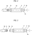
- Fig. 2 is a diagram illustrating the rod-shaped member 2, and illustrates a diagram of the state where it is attached to the tubular cell structure cultivation maintaining apparatus 1. Additionally, Fig.
- FIG. 3 is a diagram illustrating the rod-shaped member 2, and illustrates a diagram of the state where it has been detached from the tubular cell structure cultivation maintaining apparatus 1.
- the cell structure 5 was formed in, for example, the steps of Fig. 4A to Fig. 4C and the step as described above, and has a tubular structure including a hollow portion having a circular cross section inside the cell structure 5.
- a description will be given by assuming that the radius of the hollow portion having the circular cross section of the cell structure 5 is R.
- the culture chamber 3 is a sealed container, and the inside is filled with a culture solution 3a.
- the culture chamber 3 includes a first inlet 6d and a second inlet 7d for introducing the culture solution 3a into the culture chamber 3, and a first exit 6c and a second exit 7c for discharging the culture solution 3a from the culture chamber 3.
- the tubular cell structure cultivation maintaining apparatus 1 includes a first conduit 6 that fluidly connects the first exit 6c to the first inlet 6d through the pump 4, and a second conduit 7 that fluidly connects the second exit 7c to the second inlet 7d through the pump 4.
- the culture solution 3a is circulated inside the first conduit 6 and the second conduit 7 with the driving force of the pump 4.
- the first conduit 6 is mainly for supplying the culture solution 3a to the inside of the cell structure 5, and the second conduit 7 is mainly for spreading the culture solution 3a over the outside of the cell structure 5.
- the culture solution 3a flows out of the first exit 6c into a first conduit 6b, and travels toward the pump 4. Additionally, the culture solution 3a flows out of the second exit 7c into a second conduit 7b, and travels toward the pump 4. Thereafter, the culture solution 3a to which required nutrients and oxygen have been supplied at the pump 4 returns to the culture chamber 3 from the first conduit 6a through the first inlet 6d with the driving force of the pump 4. Additionally, it returns to the culture chamber 3 from the second conduit 7a through the second inlet 7d.
- the second inlet 7d, the first exit 6c, and the second exit 7c are open ends.
- the adapter 8 is attached to the first inlet 6d.
- the rod-shaped member 2 is an elongated cylindrical member having a circular cross section.
- the outer diameter of the rod-shaped member 2 is R.
- the inner diameter of the cell structure 5 is slightly larger than the outer diameter R of the rod-shaped member 2.
- the rod-shaped member 2 is tightly inserted and fit into the cell structure 5 without a gap between the cell structure 5 and the rod-shaped member 2.
- a conduit 2a is provided so as to penetrate along the axial direction in the longitudinal direction of the rod-shaped member 2 from one end to the other end of the rod-shaped member 2.
- the rod-shaped member 2 is longer than at least the length of the cell structure 5.
- a top end 2b of the rod-shaped member 2 has a tapered shape so as to be easily inserted into the hollow portion of the cell structure 5.
- the rod-shaped member 2 has a structure with oxygen permeability between the conduit 2a and the outer surface of the rod-shaped member 2.
- small through-holes for oxygen penetration may be drilled between the conduit 2a of the rod-shaped member 2 of a fluoropolymer material and the outer surface of the rod-shaped member 2.
- an oxygen permeable material such as dimethylpolysiloxane (PDMS) may be used, without arranging the small through-holes for oxygen permeation.
- PDMS dimethylpolysiloxane
- a bottom end 2c which is the opposite base of the rod-shaped member 2 to the top end 2b to which the taper is arranged, has a structure that can be fit to the adapter 8. Since a fitting port 8a of the adapter 8 can be easily inserted and fit into the conduit 2a in the bottom end 2c of the rod-shaped member 2, one-touch insertion can be performed.
- the rod-shaped member 2 can be attached to the first inlet 6d through the adapter 8, and as shown in Fig. 3 , the rod-shaped member 2 can be easily detached from the first inlet 6d through the adapter 8.
- the tubular cell structure 5 is formed, based on the method described in the background art. Then, the rod-shaped member 2 is inserted into the hollow portion of the tubular cell structure 5, so as to cause the inner surface of the cell structure 5 to adhere to the outer periphery surface of the rod-shaped member 2.
- the rod-shaped member 2 is attached to the first inlet 6d through the adapter 8 and installed in the tubular cell structure cultivation maintaining apparatus 1, and with the tubular cell structure cultivation maintaining apparatus 1, the culture solution 3a allowing permeation of oxygen is passed through the inside of the conduit 2a of the rod-shaped member 2, and the inside and outside of the cell structure 5 are immersed in the culture solution 3a, and cultured and matured for a predetermined period of time.
- the sufficient culture solution 3a is supplied to the cell structure 5 during the period of time.
- 1 tubular cell structure cultivation maintaining apparatus 2 rod-shaped member, 2a conduit, 2b top end, 2c bottom end, 3 culture chamber, 3a culture solution, 4 pump, 5 cell structure, 6 first conduit, 7 second conduit, 8 adapter, 8a fitting port
Landscapes
- Health & Medical Sciences (AREA)
- Life Sciences & Earth Sciences (AREA)
- Engineering & Computer Science (AREA)
- Wood Science & Technology (AREA)
- Organic Chemistry (AREA)
- Bioinformatics & Cheminformatics (AREA)
- Chemical & Material Sciences (AREA)
- Zoology (AREA)
- Genetics & Genomics (AREA)
- Biomedical Technology (AREA)
- Sustainable Development (AREA)
- Microbiology (AREA)
- Biotechnology (AREA)
- Biochemistry (AREA)
- General Engineering & Computer Science (AREA)
- General Health & Medical Sciences (AREA)
- Clinical Laboratory Science (AREA)
- Immunology (AREA)
- Molecular Biology (AREA)
- Apparatus Associated With Microorganisms And Enzymes (AREA)
- Micro-Organisms Or Cultivation Processes Thereof (AREA)
Description
- The present invention relates to a maintaining apparatus and a maintaining support device for a tubular cell structure including a hollow portion inside.
- Conventionally, as disclosed in
PTL 1, a technique has been known that produces a three-dimensional structure by utilizing the characteristic that cell aggregates contacting each other in an adjacent manner are fused to each other, and three-dimensionally stacking the cell aggregates (spheroids) so that cell aggregates are adjacent to each other, by utilizing a support body formed by a plurality of needle-like bodies fixed in advance to extend in the normal direction of a substrate. Here, a cell aggregate refers to a lump of a plurality of cells formed by combining and cultivating single cells. - In this technique, the technique is disclosed that extracts
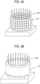
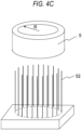
cell aggregates 51, and sticks each of thecell aggregates 51 to each of needle-like bodies of the support body to manufacture the state where the cell aggregates are skewered. For example, as inFig. 4A , for example, as acell structure 5 for blood vessel, needle-like bodies are arranged in a tubular shape, and thecell aggregates 51 are stuck to each of the needle-like bodies. When cultivated for a certain period of time, as shown inFig. 4B , theadjacent cell aggregates 51 are fused to each other, and thetubular cell structure 5 is formed on the needle-like bodies 52. Then, as shown inFig. 4C , when thecell structure 5 is pulled out from the needle-like bodies 52, thetubular cell structure 5 including a hollow portion inside the tube having a length L is extracted. -
US 2011/033927 discloses a method for making small-diameter engineered blood vessels. With regard to figure 17, the support device for the 3D-structured blood vessel is a collagen coated silicon mandrel. -
EP 1 382 670 - PTL 1: Specification of
Japanese Patent No. 4517125 - The cells constituting the
cell structure 5 have the characteristic of fusing with adjacent cells. Accordingly, when pulling out thetubular cell structure 5 from the needle-like bodies 52 to stand on its own, and preserving thecell structure 5 for only a predetermined period of time without each cell of thecell structure 5 destroyed, it is necessary to distribute a culture solution containing oxygen all over the outer surfaces and the inner surface of thecell structure 5. Additionally, further, in that case, there is a problem that, when opposing tubular walls contact each other, the cells in the contact portion are fused to each other, and a conduit is closed. - It is solved by a rod-shaped tubular cell structure maintaining support device for cultivating a tubular cell structure for a predetermined time period, the tubular cell structure including a hollow portion inside of the tubular cell structure, while maintaining the hollow portion, wherein the tubular cell structure maintaining support device includesan outer diameter insertable into the hollow portion of the cell structure, in a case where the rod-shaped tubular cell structure maintaining support device is inserted into the hollow portion, the outer diameter capable of allowing the tubular cell structure maintaining support device closely to contact an inner surface of the cell structure, and a penetration conduit including openings at both ends of the tubular cell structure maintaining support device, the penetration conduit penetrating between the openings, wherein the tubular cell structure maintaining support device has an oxygen permeable structure from the penetration conduit to an outer surface of the tubular cell structure maintaining support device.
- It is solved by a tubular cell structure cultivation maintaining apparatus for cultivating a tubular cell structure for a predetermined time period, the tubular cell structure including a hollow portion inside the tubular cell structure, while maintaining the hollow portion, wherein the tubular cell structure cultivation maintaining apparatus including a culture chamber filled with a culture solution, the culture chamber including a first inlet and a second inlet for introducing the culture solution into the culture chamber, and a first exit and a second exit for discharging the culture solution from the culture chamber, a pump for circulating the culture solution, a first conduit that fluidly connects the first exit to the first inlet through the pump, a second conduit that fluidly connects the second exit to the second inlet through the pump, a rod-shaped member insertable into the hollow portion of the cell structure, the rod-shaped member including openings at both ends of the rod-shaped member, and a penetration conduit penetrating between the openings, and an adapter attachable to the second inlet, the adapter insertable into one of the openings of the penetration conduit to be fluidly connected to the second inlet, wherein the rod-shaped member has an oxygen permeable structure from the penetration conduit to an outer surface of the rod-shaped member, the rod-shaped member including an outer diameter capable of allowing the rod-shaped member closely to contact an inner surface of the cell structure in a case where the rod-shaped member is inserted into the hollow portion.
- According to the present invention, the hollow portion of the tubular cell structure can be maintained without being closed.
-
-
Fig. 1 is a diagram illustrating a tubular cell structure cultivation maintaining apparatus in the present invention. -
Fig. 2 is a diagram illustrating a tubular cell structure maintaining support device in the present invention, and illustrating the state where it is attached to the tubular cell structure cultivation maintaining apparatus. -
Fig. 3 is a diagram illustrating a tubular cell structure cultivation maintaining apparatus in the present invention, and illustrating the state where it is separated from the tubular cell structure cultivation maintaining apparatus. -
Fig. 4A is a schematic diagram illustrating the state where cell aggregates are stuck to needle-like bodies in the step of forming a cell structure. -
Fig. 4B is a schematic diagram illustrating the state where the adjacent cell aggregates are fused to each other to form the cell structure in the step of forming the cell structure. -
Fig. 4C is a schematic diagram illustrating the state showing the step of pulling out the formed cell structure from the needle-like bodies in the step of forming the cell structure. - First, referring to
Fig. 1 to Fig. 3 , a tubular cell structurecultivation maintaining apparatus 1 of the present invention will be described.Fig. 1 is a schematic diagram of the tubular cell structurecultivation maintaining apparatus 1 of an embodiment of the present invention. The tubular cell structurecultivation maintaining apparatus 1 includes a rod-shaped member 2 serving as a maintaining support device of thetubular cell structure 5, aculture chamber 3, a pump 4, afirst conduit 6, asecond conduit 7, and anadapter 8.Fig. 2 is a diagram illustrating the rod-shaped member 2, and illustrates a diagram of the state where it is attached to the tubular cell structurecultivation maintaining apparatus 1. Additionally,Fig. 3 is a diagram illustrating the rod-shaped member 2, and illustrates a diagram of the state where it has been detached from the tubular cell structurecultivation maintaining apparatus 1. Thecell structure 5 was formed in, for example, the steps ofFig. 4A to Fig. 4C and the step as described above, and has a tubular structure including a hollow portion having a circular cross section inside thecell structure 5. In this specification, a description will be given by assuming that the radius of the hollow portion having the circular cross section of thecell structure 5 is R. - The
culture chamber 3 is a sealed container, and the inside is filled with aculture solution 3a. Theculture chamber 3 includes afirst inlet 6d and asecond inlet 7d for introducing theculture solution 3a into theculture chamber 3, and afirst exit 6c and asecond exit 7c for discharging theculture solution 3a from theculture chamber 3. The tubular cell structurecultivation maintaining apparatus 1 includes afirst conduit 6 that fluidly connects thefirst exit 6c to thefirst inlet 6d through the pump 4, and asecond conduit 7 that fluidly connects thesecond exit 7c to thesecond inlet 7d through the pump 4. Theculture solution 3a is circulated inside thefirst conduit 6 and thesecond conduit 7 with the driving force of the pump 4. Thefirst conduit 6 is mainly for supplying theculture solution 3a to the inside of thecell structure 5, and thesecond conduit 7 is mainly for spreading theculture solution 3a over the outside of thecell structure 5. - That is, when the
culture chamber 3 filled with theculture solution 3a is seen as the starting point, theculture solution 3a flows out of thefirst exit 6c into afirst conduit 6b, and travels toward the pump 4. Additionally, theculture solution 3a flows out of thesecond exit 7c into asecond conduit 7b, and travels toward the pump 4. Thereafter, theculture solution 3a to which required nutrients and oxygen have been supplied at the pump 4 returns to theculture chamber 3 from thefirst conduit 6a through thefirst inlet 6d with the driving force of the pump 4. Additionally, it returns to theculture chamber 3 from thesecond conduit 7a through thesecond inlet 7d. Thesecond inlet 7d, thefirst exit 6c, and thesecond exit 7c are open ends. Theadapter 8 is attached to thefirst inlet 6d. - The rod-
shaped member 2 is an elongated cylindrical member having a circular cross section. The outer diameter of the rod-shaped member 2 is R. At the stage of maintaining thecell structure 5, when the rod-shaped member 2 is inserted into thecell structure 5, the inner diameter of thecell structure 5 is slightly larger than the outer diameter R of the rod-shaped member 2. However, since the inner diameter of thecell structure 5 has the characteristic of gradually contracting in the course of maturation of cells that constitute thecell structure 5 with the elapse of time in the state where cultivation is being performed, the rod-shaped member 2 is tightly inserted and fit into thecell structure 5 without a gap between thecell structure 5 and the rod-shaped member 2. In the inside, aconduit 2a is provided so as to penetrate along the axial direction in the longitudinal direction of the rod-shaped member 2 from one end to the other end of the rod-shaped member 2. As for the length of the rod-shaped member 2, the rod-shaped member 2 is longer than at least the length of thecell structure 5. Atop end 2b of the rod-shaped member 2 has a tapered shape so as to be easily inserted into the hollow portion of thecell structure 5. - The rod-
shaped member 2 has a structure with oxygen permeability between theconduit 2a and the outer surface of the rod-shaped member 2. For example, small through-holes for oxygen penetration may be drilled between theconduit 2a of the rod-shapedmember 2 of a fluoropolymer material and the outer surface of the rod-shapedmember 2. Alternatively, an oxygen permeable material such as dimethylpolysiloxane (PDMS) may be used, without arranging the small through-holes for oxygen permeation. By introducing the oxygen-dissolvedculture solution 3a into theconduit 2a, as theculture solution 3a passes, oxygen reaches the outer surface of the rod-shapedmember 2, and thecell structure 5 can accept oxygen from the inner surface over the entire length of thecell structure 5. - A
bottom end 2c, which is the opposite base of the rod-shapedmember 2 to thetop end 2b to which the taper is arranged, has a structure that can be fit to theadapter 8. Since afitting port 8a of theadapter 8 can be easily inserted and fit into theconduit 2a in thebottom end 2c of the rod-shapedmember 2, one-touch insertion can be performed. For example, as inFig. 2 , the rod-shapedmember 2 can be attached to thefirst inlet 6d through theadapter 8, and as shown inFig. 3 , the rod-shapedmember 2 can be easily detached from thefirst inlet 6d through theadapter 8. - Subsequently, how to use the tubular cell structure
cultivation maintaining apparatus 1 and the rod-shapedmember 2 serving as the tubular cell structure maintaining support device will be described. First, thetubular cell structure 5 is formed, based on the method described in the background art. Then, the rod-shapedmember 2 is inserted into the hollow portion of thetubular cell structure 5, so as to cause the inner surface of thecell structure 5 to adhere to the outer periphery surface of the rod-shapedmember 2. In this state, in the state where the rod-shapedmember 2 has been inserted into the hollow portion of thecell structure 5, the rod-shapedmember 2 is attached to thefirst inlet 6d through theadapter 8 and installed in the tubular cell structurecultivation maintaining apparatus 1, and with the tubular cell structurecultivation maintaining apparatus 1, theculture solution 3a allowing permeation of oxygen is passed through the inside of theconduit 2a of the rod-shapedmember 2, and the inside and outside of thecell structure 5 are immersed in theculture solution 3a, and cultured and matured for a predetermined period of time. Thesufficient culture solution 3a is supplied to thecell structure 5 during the period of time. - 1 tubular cell structure cultivation maintaining apparatus, 2 rod-shaped member, 2a conduit, 2b top end, 2c bottom end, 3 culture chamber, 3a culture solution, 4 pump, 5 cell structure, 6 first conduit, 7 second conduit, 8 adapter, 8a fitting port
Claims (8)
- A rod-shaped tubular cell structure maintaining support device (2) for fer cultivating a tubular cell structure (5) for a predetermined time period, the tubular cell structure including a hollow portion inside of the tubular cell structure, and maintaining the hollow portion,
wherein the tubular cell structure maintaining support device (2) comprises:an outer diameter insertable into the hollow portion of the tubular cell structure (5), in a case where the rod-shaped tubular cell structure maintaining support device (2) is inserted into the hollow portion, the outer diameter capable of allowing the tubular cell structure maintaining support device (2) closely to contact an inner surface of the tubular cell structure (5); anda penetration conduit (2a) including openings at both ends of the tubular cell structure maintaining support device (2), the penetration conduit penetrating between the openings,wherein the tubular cell structure maintaining support device has an oxygen permeable structure from the penetration conduit to an outer surface of the tubular cell structure maintaining support device. - A tubular cell structure maintaining support device according to claim 1, wherein the oxygen permeable structure is provided by making the tubular cell structure maintaining support device with an oxygen permeable material.
- A tubular cell structure maintaining support device according to claim 2, wherein the oxygen permeable material is dimethylpolysiloxane.
- A tubular cell structure maintaining support device according to claim 1, wherein the tubular cell structure maintaining support device is made of a fluoropolymer material, and the oxygen permeable structure is holes penetrating from the penetration conduit to the outer surface of the tubular cell structure maintaining support device.
- A tubular cell structure cultivation maintaining apparatus (1) for cultivating a tubular cell structure for a predetermined time period, the tubular cell structure (5) including a hollow portion inside the tubular cell structure, and maintaining the hollow portion, wherein the tubular cell structure cultivation maintaining apparatus comprises:a culture chamber (3) filled with a culture solution, the culture chamber including a first inlet 6d) and a second inlet (7d) for introducing the culture solution into the culture chamber (8) and a first exit (6c) and a second exit (7c) for discharging the culture solution from the culture chamber;a pump for circulating the culture solution; a first conduit (6) that fluidly connects the first exit to the first inlet through the pump (4);a second conduit (7) that fluidly connects the second exit to the second inlet through the pump;a rod-shaped member insertable into the hollow portion of the tubular cell structure, the rod-shaped member including openings at both ends of the rod-shaped member, and a penetration conduit (2a) penetrating between the openings; andan adapter attachable to the second inlet, the adapter insertable into one of the openings of the penetration conduit to be fluidly connected to the second inlet,wherein the rod-shaped member (2) has an oxygen permeable structure from the penetration conduit to an outer surface of the rod-shaped member, the rod-shaped member including an outer diameter capable of allowing the rod-shaped member closely to contact an inner surface of the tubular cell structure in a case where the rod-shaped member is inserted into the hollow portion.
- A tubular cell structure cultivation maintaining apparatus according to claim 5, wherein the oxygen permeable structure is provided by making the rod-shaped member with an oxygen permeable material.
- A tubular cell structure cultivation maintaining apparatus according to claim 6, wherein the oxygen permeable material is dimethylpolysiloxane.
- A tubular cell structure cultivation maintaining apparatus according to claim 5, wherein the rod-shaped member is made of a fluoropolymer material, and the oxygen permeable structure is holes penetrating from the penetration conduit to the outer surface of the rod-shaped member.
Applications Claiming Priority (1)
| Application Number | Priority Date | Filing Date | Title |
|---|---|---|---|
| PCT/JP2018/014895 WO2019198126A1 (en) | 2018-04-09 | 2018-04-09 | Device for maintaining culture of tubular cell structure and auxiliary tool for maintaining tubular cell structure |
Publications (4)
| Publication Number | Publication Date |
|---|---|
| EP3778859A1 EP3778859A1 (en) | 2021-02-17 |
| EP3778859A4 EP3778859A4 (en) | 2021-04-14 |
| EP3778859C0 EP3778859C0 (en) | 2024-09-18 |
| EP3778859B1 true EP3778859B1 (en) | 2024-09-18 |
Family
ID=68163969
Family Applications (1)
| Application Number | Title | Priority Date | Filing Date |
|---|---|---|---|
| EP18914693.9A Active EP3778859B1 (en) | 2018-04-09 | 2018-04-09 | Device for maintaining culture of tubular cell structure and auxiliary tool for maintaining tubular cell structure |
Country Status (4)
| Country | Link |
|---|---|
| US (1) | US12037573B2 (en) |
| EP (1) | EP3778859B1 (en) |
| JP (1) | JP7148998B2 (en) |
| WO (1) | WO2019198126A1 (en) |
Families Citing this family (3)
| Publication number | Priority date | Publication date | Assignee | Title |
|---|---|---|---|---|
| KR102354752B1 (en) * | 2021-02-26 | 2022-01-21 | 김재훈 | Microalgae cultivation container for biofuel production |
| EP4674943A1 (en) * | 2024-07-04 | 2026-01-07 | Cellular Agriculture Ltd | A meat culture construct for a meat culturing system |
| WO2026008773A1 (en) * | 2024-07-04 | 2026-01-08 | Cellular Agriculture Ltd | Cell culture construct |
Family Cites Families (22)
| Publication number | Priority date | Publication date | Assignee | Title |
|---|---|---|---|---|
| US5490933A (en) * | 1991-04-04 | 1996-02-13 | The Dow Chemical Company | Self-regulated biological scrubber and/or gas stripper for the treatment of fluid streams |
| US5792603A (en) * | 1995-04-27 | 1998-08-11 | Advanced Tissue Sciences, Inc. | Apparatus and method for sterilizing, seeding, culturing, storing, shipping and testing tissue, synthetic or native, vascular grafts |
| WO1996037165A1 (en) * | 1995-05-26 | 1996-11-28 | Bsi Corporation | Method and implantable article for promoting endothelialization |
| EP2075015B1 (en) * | 1997-07-03 | 2015-03-11 | Massachusetts Institute of Technology | Tissue-engineered constructs |
| JP2002315566A (en) * | 2001-04-24 | 2002-10-29 | Takagi Ind Co Ltd | Cell / tissue culture equipment |
| GB0121986D0 (en) * | 2001-09-11 | 2001-10-31 | Isis Innovation | Method and structure for growing living organic tissue |
| CA2528134C (en) | 2003-06-04 | 2015-05-12 | University Of South Carolina | Tissue scaffold having aligned fibrils, apparatus and method for producing the same, and artificial tissue and methods of use thereof |
| DE102005001747A1 (en) * | 2004-12-21 | 2006-07-06 | Minucells And Minutissue Vertriebs Gmbh | Culture system for luminal structures, e.g. arteries or tissues, has the structure connected to an inlet or outlet tube by a connector which is removable from the chamber |
| JP2006311887A (en) * | 2005-05-06 | 2006-11-16 | Imoto Seisakusho:Kk | Biological tubular organ culture method and apparatus |
| JP4517125B2 (en) | 2007-03-30 | 2010-08-04 | 国立大学法人九州大学 | Method for producing three-dimensional structure of cells |
| US20110033927A1 (en) * | 2009-04-01 | 2011-02-10 | Worcester Polytechnic Institute | Methods of generating small-diameter tissue engineered blood vessels |
| WO2011146046A1 (en) | 2010-05-17 | 2011-11-24 | Yale University | System for seeding cells onto three dimensional scaffolds |
| US9090863B2 (en) * | 2010-05-17 | 2015-07-28 | Pall Corporation | System for seeding cells onto three dimensional scaffolds |
| JP5674442B2 (en) * | 2010-12-08 | 2015-02-25 | 国立大学法人 東京大学 | Three-dimensional cell culture containing blood vessel-like structures |
| JP6439918B2 (en) * | 2014-10-17 | 2018-12-19 | 国立大学法人 東京大学 | Method for producing three-dimensional cell structure |
| US20170342373A1 (en) * | 2014-12-30 | 2017-11-30 | Agency For Science, Technology And Research | Technique for formation and assembly of 3d cellular structures |
| WO2016204217A1 (en) * | 2015-06-16 | 2016-12-22 | 国立大学法人 奈良先端科学技術大学院大学 | Biocompatible material, coating composition, coating film, and article |
| ES3038189T3 (en) * | 2015-12-11 | 2025-10-10 | Res Inst Nationwide Childrens Hospital | Systems and methods for optimized patient specific tissue engineering vascular grafts |
| JPWO2017104558A1 (en) * | 2015-12-15 | 2018-10-04 | 東洋紡株式会社 | Hollow fiber membrane and hollow fiber module for cell culture |
| JP6696206B2 (en) * | 2016-02-17 | 2020-05-20 | 東洋紡株式会社 | Cell culture device using gas impermeable tube and cell culture method |
| WO2018029970A1 (en) * | 2016-08-10 | 2018-02-15 | Cyberdyne株式会社 | Method for producing three-dimensional structure of cells and system for producing three-dimensional structure |
| AU2019234581A1 (en) * | 2018-03-13 | 2020-10-01 | Frontier Bio Corporation | Electrohydrodynamic bioprinter system and method |
-
2018
- 2018-04-09 JP JP2020512951A patent/JP7148998B2/en active Active
- 2018-04-09 WO PCT/JP2018/014895 patent/WO2019198126A1/en not_active Ceased
- 2018-04-09 US US17/046,114 patent/US12037573B2/en active Active
- 2018-04-09 EP EP18914693.9A patent/EP3778859B1/en active Active
Also Published As
| Publication number | Publication date |
|---|---|
| US20210032585A1 (en) | 2021-02-04 |
| EP3778859C0 (en) | 2024-09-18 |
| EP3778859A1 (en) | 2021-02-17 |
| JP7148998B2 (en) | 2022-10-06 |
| WO2019198126A1 (en) | 2019-10-17 |
| JPWO2019198126A1 (en) | 2021-04-15 |
| US12037573B2 (en) | 2024-07-16 |
| EP3778859A4 (en) | 2021-04-14 |
Similar Documents
| Publication | Publication Date | Title |
|---|---|---|
| FI77785B (en) | DIALYSPROB. | |
| EP3778859A1 (en) | Device for maintaining culture of tubular cell structure and auxiliary tool for maintaining tubular cell structure | |
| CN106536707A (en) | Method and apparatus to prepare cardiac organoids in bioreactor system | |
| JP5674442B2 (en) | Three-dimensional cell culture containing blood vessel-like structures | |
| JP7055386B2 (en) | Fluid chips for cell culture, culture vessels and culture methods | |
| EP1087010A2 (en) | Bioreactor with single-use pump | |
| US10967371B2 (en) | Methods and apparatus for controlling flow in a microfluidic arrangement, and a microfluidic arrangement | |
| US20170355940A1 (en) | Method for vascularizing in-vitro generated or ex-vivo tissue fragments in a microfluidic device | |
| JP2020535848A (en) | Cell containment device | |
| EP3498822B1 (en) | Method for producing three-dimensional structure of cells and system for producing three-dimensional structure | |
| WO2016154882A1 (en) | Rotary device for biological printing, and method of use thereof | |
| US20220033749A1 (en) | Cell culture chip | |
| EP2468846A1 (en) | A method of examining tissue growth and conditioning of cells on a scaffold and a perfusion bioreactor | |
| CN101687064B (en) | Method for preparing cell-free organic tissue | |
| US9962535B2 (en) | Hollow silica glass microneedle arrays and method and apparatus for manufacturing same | |
| KR102138699B1 (en) | Mushroom culture medium and manufacturing method thereof | |
| KR101856379B1 (en) | Method for seeding cell | |
| CA3070413A1 (en) | Apparatuses and methods using nanostraws to deliver biologically relevant cargo into non-adherent cells | |
| WO2018062655A1 (en) | Cell culturing apparatus and cell culturing method using same | |
| RU2523388C2 (en) | Cell-free organic tissue prepared for vitality recovery and methods for preparing it | |
| CN106137456A (en) | A kind of whirligig for biometric print and using method thereof | |
| KR101433091B1 (en) | Chematoxis Analysis Microfluidic Apparatus of bacteria, Production Method and Chematoxis Analysis Method of bacteria | |
| KR101846732B1 (en) | In vitro cultivation method for growing neuron | |
| EP4596671A1 (en) | Luminal structure, and method for manufacturing luminal structure | |
| EP3778850A1 (en) | Method for connecting cell structures and auxiliary connector |
Legal Events
| Date | Code | Title | Description |
|---|---|---|---|
| STAA | Information on the status of an ep patent application or granted ep patent |
Free format text: STATUS: THE INTERNATIONAL PUBLICATION HAS BEEN MADE |
|
| PUAI | Public reference made under article 153(3) epc to a published international application that has entered the european phase |
Free format text: ORIGINAL CODE: 0009012 |
|
| STAA | Information on the status of an ep patent application or granted ep patent |
Free format text: STATUS: REQUEST FOR EXAMINATION WAS MADE |
|
| 17P | Request for examination filed |
Effective date: 20201104 |
|
| AK | Designated contracting states |
Kind code of ref document: A1 Designated state(s): AL AT BE BG CH CY CZ DE DK EE ES FI FR GB GR HR HU IE IS IT LI LT LU LV MC MK MT NL NO PL PT RO RS SE SI SK SM TR |
|
| AX | Request for extension of the european patent |
Extension state: BA ME |
|
| A4 | Supplementary search report drawn up and despatched |
Effective date: 20210316 |
|
| RIC1 | Information provided on ipc code assigned before grant |
Ipc: C12M 3/00 20060101AFI20210309BHEP Ipc: C12N 5/071 20100101ALI20210309BHEP Ipc: C12M 1/40 20060101ALI20210309BHEP Ipc: C12M 1/12 20060101ALI20210309BHEP Ipc: C12M 1/00 20060101ALI20210309BHEP Ipc: C12M 1/04 20060101ALI20210309BHEP |
|
| DAV | Request for validation of the european patent (deleted) | ||
| DAX | Request for extension of the european patent (deleted) | ||
| GRAP | Despatch of communication of intention to grant a patent |
Free format text: ORIGINAL CODE: EPIDOSNIGR1 |
|
| STAA | Information on the status of an ep patent application or granted ep patent |
Free format text: STATUS: GRANT OF PATENT IS INTENDED |
|
| INTG | Intention to grant announced |
Effective date: 20240430 |
|
| GRAS | Grant fee paid |
Free format text: ORIGINAL CODE: EPIDOSNIGR3 |
|
| GRAA | (expected) grant |
Free format text: ORIGINAL CODE: 0009210 |
|
| STAA | Information on the status of an ep patent application or granted ep patent |
Free format text: STATUS: THE PATENT HAS BEEN GRANTED |
|
| AK | Designated contracting states |
Kind code of ref document: B1 Designated state(s): AL AT BE BG CH CY CZ DE DK EE ES FI FR GB GR HR HU IE IS IT LI LT LU LV MC MK MT NL NO PL PT RO RS SE SI SK SM TR |
|
| REG | Reference to a national code |
Ref country code: GB Ref legal event code: FG4D |
|
| REG | Reference to a national code |
Ref country code: CH Ref legal event code: EP |
|
| REG | Reference to a national code |
Ref country code: IE Ref legal event code: FG4D |
|
| REG | Reference to a national code |
Ref country code: DE Ref legal event code: R096 Ref document number: 602018074619 Country of ref document: DE |
|
| U01 | Request for unitary effect filed |
Effective date: 20240924 |
|
| U07 | Unitary effect registered |
Designated state(s): AT BE BG DE DK EE FI FR IT LT LU LV MT NL PT RO SE SI Effective date: 20241016 |
|
| PG25 | Lapsed in a contracting state [announced via postgrant information from national office to epo] |
Ref country code: NO Free format text: LAPSE BECAUSE OF FAILURE TO SUBMIT A TRANSLATION OF THE DESCRIPTION OR TO PAY THE FEE WITHIN THE PRESCRIBED TIME-LIMIT Effective date: 20241218 |
|
| PG25 | Lapsed in a contracting state [announced via postgrant information from national office to epo] |
Ref country code: GR Free format text: LAPSE BECAUSE OF FAILURE TO SUBMIT A TRANSLATION OF THE DESCRIPTION OR TO PAY THE FEE WITHIN THE PRESCRIBED TIME-LIMIT Effective date: 20241219 |
|
| PG25 | Lapsed in a contracting state [announced via postgrant information from national office to epo] |
Ref country code: HR Free format text: LAPSE BECAUSE OF FAILURE TO SUBMIT A TRANSLATION OF THE DESCRIPTION OR TO PAY THE FEE WITHIN THE PRESCRIBED TIME-LIMIT Effective date: 20240918 |
|
| PG25 | Lapsed in a contracting state [announced via postgrant information from national office to epo] |
Ref country code: RS Free format text: LAPSE BECAUSE OF FAILURE TO SUBMIT A TRANSLATION OF THE DESCRIPTION OR TO PAY THE FEE WITHIN THE PRESCRIBED TIME-LIMIT Effective date: 20241218 |
|
| PG25 | Lapsed in a contracting state [announced via postgrant information from national office to epo] |
Ref country code: RS Free format text: LAPSE BECAUSE OF FAILURE TO SUBMIT A TRANSLATION OF THE DESCRIPTION OR TO PAY THE FEE WITHIN THE PRESCRIBED TIME-LIMIT Effective date: 20241218 Ref country code: NO Free format text: LAPSE BECAUSE OF FAILURE TO SUBMIT A TRANSLATION OF THE DESCRIPTION OR TO PAY THE FEE WITHIN THE PRESCRIBED TIME-LIMIT Effective date: 20241218 Ref country code: HR Free format text: LAPSE BECAUSE OF FAILURE TO SUBMIT A TRANSLATION OF THE DESCRIPTION OR TO PAY THE FEE WITHIN THE PRESCRIBED TIME-LIMIT Effective date: 20240918 Ref country code: GR Free format text: LAPSE BECAUSE OF FAILURE TO SUBMIT A TRANSLATION OF THE DESCRIPTION OR TO PAY THE FEE WITHIN THE PRESCRIBED TIME-LIMIT Effective date: 20241219 |
|
| PG25 | Lapsed in a contracting state [announced via postgrant information from national office to epo] |
Ref country code: IS Free format text: LAPSE BECAUSE OF FAILURE TO SUBMIT A TRANSLATION OF THE DESCRIPTION OR TO PAY THE FEE WITHIN THE PRESCRIBED TIME-LIMIT Effective date: 20250118 |
|
| PG25 | Lapsed in a contracting state [announced via postgrant information from national office to epo] |
Ref country code: SM Free format text: LAPSE BECAUSE OF FAILURE TO SUBMIT A TRANSLATION OF THE DESCRIPTION OR TO PAY THE FEE WITHIN THE PRESCRIBED TIME-LIMIT Effective date: 20240918 |
|
| PG25 | Lapsed in a contracting state [announced via postgrant information from national office to epo] |
Ref country code: ES Free format text: LAPSE BECAUSE OF FAILURE TO SUBMIT A TRANSLATION OF THE DESCRIPTION OR TO PAY THE FEE WITHIN THE PRESCRIBED TIME-LIMIT Effective date: 20240918 |
|
| PG25 | Lapsed in a contracting state [announced via postgrant information from national office to epo] |
Ref country code: CZ Free format text: LAPSE BECAUSE OF FAILURE TO SUBMIT A TRANSLATION OF THE DESCRIPTION OR TO PAY THE FEE WITHIN THE PRESCRIBED TIME-LIMIT Effective date: 20240918 Ref country code: PL Free format text: LAPSE BECAUSE OF FAILURE TO SUBMIT A TRANSLATION OF THE DESCRIPTION OR TO PAY THE FEE WITHIN THE PRESCRIBED TIME-LIMIT Effective date: 20240918 |
|
| PG25 | Lapsed in a contracting state [announced via postgrant information from national office to epo] |
Ref country code: SK Free format text: LAPSE BECAUSE OF FAILURE TO SUBMIT A TRANSLATION OF THE DESCRIPTION OR TO PAY THE FEE WITHIN THE PRESCRIBED TIME-LIMIT Effective date: 20240918 |
|
| U20 | Renewal fee for the european patent with unitary effect paid |
Year of fee payment: 8 Effective date: 20250417 |
|
| PLBE | No opposition filed within time limit |
Free format text: ORIGINAL CODE: 0009261 |
|
| STAA | Information on the status of an ep patent application or granted ep patent |
Free format text: STATUS: NO OPPOSITION FILED WITHIN TIME LIMIT |
|
| 26N | No opposition filed |
Effective date: 20250619 |
|
| REG | Reference to a national code |
Ref country code: CH Ref legal event code: H13 Free format text: ST27 STATUS EVENT CODE: U-0-0-H10-H13 (AS PROVIDED BY THE NATIONAL OFFICE) Effective date: 20251125 |
|
| PG25 | Lapsed in a contracting state [announced via postgrant information from national office to epo] |
Ref country code: MC Free format text: LAPSE BECAUSE OF FAILURE TO SUBMIT A TRANSLATION OF THE DESCRIPTION OR TO PAY THE FEE WITHIN THE PRESCRIBED TIME-LIMIT Effective date: 20240918 |
|
| PG25 | Lapsed in a contracting state [announced via postgrant information from national office to epo] |
Ref country code: CH Free format text: LAPSE BECAUSE OF NON-PAYMENT OF DUE FEES Effective date: 20250430 |
|
| PGFP | Annual fee paid to national office [announced via postgrant information from national office to epo] |
Ref country code: GB Payment date: 20260330 Year of fee payment: 9 |
|
| PG25 | Lapsed in a contracting state [announced via postgrant information from national office to epo] |
Ref country code: IE Free format text: LAPSE BECAUSE OF NON-PAYMENT OF DUE FEES Effective date: 20250409 |
|
| U20 | Renewal fee for the european patent with unitary effect paid |
Year of fee payment: 9 Effective date: 20260330 |