EP3778509A1 - Method for manufacturing glass panel unit, and method for manufacturing glass window - Google Patents
Method for manufacturing glass panel unit, and method for manufacturing glass window Download PDFInfo
- Publication number
- EP3778509A1 EP3778509A1 EP19774963.3A EP19774963A EP3778509A1 EP 3778509 A1 EP3778509 A1 EP 3778509A1 EP 19774963 A EP19774963 A EP 19774963A EP 3778509 A1 EP3778509 A1 EP 3778509A1
- Authority
- EP
- European Patent Office
- Prior art keywords
- panel
- glass
- internal space
- thermal adhesive
- space
- Prior art date
- Legal status (The legal status is an assumption and is not a legal conclusion. Google has not performed a legal analysis and makes no representation as to the accuracy of the status listed.)
- Pending
Links
Images


Classifications
-
- E—FIXED CONSTRUCTIONS
- E06—DOORS, WINDOWS, SHUTTERS, OR ROLLER BLINDS IN GENERAL; LADDERS
- E06B—FIXED OR MOVABLE CLOSURES FOR OPENINGS IN BUILDINGS, VEHICLES, FENCES OR LIKE ENCLOSURES IN GENERAL, e.g. DOORS, WINDOWS, BLINDS, GATES
- E06B3/00—Window sashes, door leaves, or like elements for closing wall or like openings; Layout of fixed or moving closures, e.g. windows in wall or like openings; Features of rigidly-mounted outer frames relating to the mounting of wing frames
- E06B3/66—Units comprising two or more parallel glass or like panes permanently secured together
- E06B3/677—Evacuating or filling the gap between the panes ; Equilibration of inside and outside pressure; Preventing condensation in the gap between the panes; Cleaning the gap between the panes
- E06B3/6775—Evacuating or filling the gap during assembly
-
- C—CHEMISTRY; METALLURGY
- C03—GLASS; MINERAL OR SLAG WOOL
- C03C—CHEMICAL COMPOSITION OF GLASSES, GLAZES OR VITREOUS ENAMELS; SURFACE TREATMENT OF GLASS; SURFACE TREATMENT OF FIBRES OR FILAMENTS MADE FROM GLASS, MINERALS OR SLAGS; JOINING GLASS TO GLASS OR OTHER MATERIALS
- C03C27/00—Joining pieces of glass to pieces of other inorganic material; Joining glass to glass other than by fusing
- C03C27/06—Joining glass to glass by processes other than fusing
- C03C27/10—Joining glass to glass by processes other than fusing with the aid of adhesive specially adapted for that purpose
-
- C—CHEMISTRY; METALLURGY
- C03—GLASS; MINERAL OR SLAG WOOL
- C03C—CHEMICAL COMPOSITION OF GLASSES, GLAZES OR VITREOUS ENAMELS; SURFACE TREATMENT OF GLASS; SURFACE TREATMENT OF FIBRES OR FILAMENTS MADE FROM GLASS, MINERALS OR SLAGS; JOINING GLASS TO GLASS OR OTHER MATERIALS
- C03C8/00—Enamels; Glazes; Fusion seal compositions being frit compositions having non-frit additions
- C03C8/02—Frit compositions, i.e. in a powdered or comminuted form
- C03C8/10—Frit compositions, i.e. in a powdered or comminuted form containing lead
-
- E—FIXED CONSTRUCTIONS
- E06—DOORS, WINDOWS, SHUTTERS, OR ROLLER BLINDS IN GENERAL; LADDERS
- E06B—FIXED OR MOVABLE CLOSURES FOR OPENINGS IN BUILDINGS, VEHICLES, FENCES OR LIKE ENCLOSURES IN GENERAL, e.g. DOORS, WINDOWS, BLINDS, GATES
- E06B3/00—Window sashes, door leaves, or like elements for closing wall or like openings; Layout of fixed or moving closures, e.g. windows in wall or like openings; Features of rigidly-mounted outer frames relating to the mounting of wing frames
- E06B3/66—Units comprising two or more parallel glass or like panes permanently secured together
- E06B3/6612—Evacuated glazing units
-
- E—FIXED CONSTRUCTIONS
- E06—DOORS, WINDOWS, SHUTTERS, OR ROLLER BLINDS IN GENERAL; LADDERS
- E06B—FIXED OR MOVABLE CLOSURES FOR OPENINGS IN BUILDINGS, VEHICLES, FENCES OR LIKE ENCLOSURES IN GENERAL, e.g. DOORS, WINDOWS, BLINDS, GATES
- E06B3/00—Window sashes, door leaves, or like elements for closing wall or like openings; Layout of fixed or moving closures, e.g. windows in wall or like openings; Features of rigidly-mounted outer frames relating to the mounting of wing frames
- E06B3/66—Units comprising two or more parallel glass or like panes permanently secured together
- E06B3/663—Elements for spacing panes
- E06B3/66309—Section members positioned at the edges of the glazing unit
- E06B3/66333—Section members positioned at the edges of the glazing unit of unusual substances, e.g. wood or other fibrous materials, glass or other transparent materials
-
- E—FIXED CONSTRUCTIONS
- E06—DOORS, WINDOWS, SHUTTERS, OR ROLLER BLINDS IN GENERAL; LADDERS
- E06B—FIXED OR MOVABLE CLOSURES FOR OPENINGS IN BUILDINGS, VEHICLES, FENCES OR LIKE ENCLOSURES IN GENERAL, e.g. DOORS, WINDOWS, BLINDS, GATES
- E06B3/00—Window sashes, door leaves, or like elements for closing wall or like openings; Layout of fixed or moving closures, e.g. windows in wall or like openings; Features of rigidly-mounted outer frames relating to the mounting of wing frames
- E06B3/66—Units comprising two or more parallel glass or like panes permanently secured together
- E06B3/673—Assembling the units
- E06B3/67339—Working the edges of already assembled units
- E06B3/6736—Heat treatment
-
- E—FIXED CONSTRUCTIONS
- E06—DOORS, WINDOWS, SHUTTERS, OR ROLLER BLINDS IN GENERAL; LADDERS
- E06B—FIXED OR MOVABLE CLOSURES FOR OPENINGS IN BUILDINGS, VEHICLES, FENCES OR LIKE ENCLOSURES IN GENERAL, e.g. DOORS, WINDOWS, BLINDS, GATES
- E06B3/00—Window sashes, door leaves, or like elements for closing wall or like openings; Layout of fixed or moving closures, e.g. windows in wall or like openings; Features of rigidly-mounted outer frames relating to the mounting of wing frames
- E06B3/66—Units comprising two or more parallel glass or like panes permanently secured together
- E06B3/677—Evacuating or filling the gap between the panes ; Equilibration of inside and outside pressure; Preventing condensation in the gap between the panes; Cleaning the gap between the panes
-
- E—FIXED CONSTRUCTIONS
- E06—DOORS, WINDOWS, SHUTTERS, OR ROLLER BLINDS IN GENERAL; LADDERS
- E06B—FIXED OR MOVABLE CLOSURES FOR OPENINGS IN BUILDINGS, VEHICLES, FENCES OR LIKE ENCLOSURES IN GENERAL, e.g. DOORS, WINDOWS, BLINDS, GATES
- E06B3/00—Window sashes, door leaves, or like elements for closing wall or like openings; Layout of fixed or moving closures, e.g. windows in wall or like openings; Features of rigidly-mounted outer frames relating to the mounting of wing frames
- E06B3/66—Units comprising two or more parallel glass or like panes permanently secured together
- E06B3/663—Elements for spacing panes
- E06B3/66309—Section members positioned at the edges of the glazing unit
- E06B3/66333—Section members positioned at the edges of the glazing unit of unusual substances, e.g. wood or other fibrous materials, glass or other transparent materials
- E06B2003/66338—Section members positioned at the edges of the glazing unit of unusual substances, e.g. wood or other fibrous materials, glass or other transparent materials of glass
-
- E—FIXED CONSTRUCTIONS
- E06—DOORS, WINDOWS, SHUTTERS, OR ROLLER BLINDS IN GENERAL; LADDERS
- E06B—FIXED OR MOVABLE CLOSURES FOR OPENINGS IN BUILDINGS, VEHICLES, FENCES OR LIKE ENCLOSURES IN GENERAL, e.g. DOORS, WINDOWS, BLINDS, GATES
- E06B3/00—Window sashes, door leaves, or like elements for closing wall or like openings; Layout of fixed or moving closures, e.g. windows in wall or like openings; Features of rigidly-mounted outer frames relating to the mounting of wing frames
- E06B3/66—Units comprising two or more parallel glass or like panes permanently secured together
- E06B3/663—Elements for spacing panes
- E06B3/66304—Discrete spacing elements, e.g. for evacuated glazing units
Definitions
- the present invention relates to a method for manufacturing a glass panel unit and a method for manufacturing a glass window.
- Patent Literature 1 discloses an insulated glazing including a pair of flat glass panes facing each other with a prescribed distance therebetween and a method for manufacturing the insulated glazing.
- the method for manufacturing the insulated glazing disclosed in Patent Literature 1 includes a first melting step of achieving a temperature higher than or equal to a softening point temperature of glass frit contained in a frit seal and a partition. In this way, peripheral portions of the pair of flat glass panes are sealed together, thereby forming a space which is hermetically closable. The space is evacuated, and then, a second melting step is performed to heat the pair of flat glass panes and the glass frit, thereby sealing an evacuation port.
- Patent Literature 1 Since the method for manufacturing the insulated glazing disclosed in Patent Literature 1 heats the pair of flat glass panes and the entirety of the glass frit in the second melting step, a large quantity of unnecessary gas is released from the entirety of the glass frit, which may lower the degree of vacuum of the space.
- Patent Literature 1 JP 2015-147727 A
- One of the objectives of the present disclosure is to provide a method for manufacturing a glass panel unit which releases a reduced quantity of unnecessary gas and a method for manufacturing a glass window.
- a method for manufacturing a glass panel unit of one aspect of the present disclosure includes: an adhesive disposing step, a glass composite generation step, an internal space forming step, an evacuation step, and an evacuated space forming step.
- the adhesive disposing step is a step of disposing a thermal adhesive on a first panel or a second panel.
- the glass composite generation step is a step of disposing the second panel to face the first panel to generate a glass composite including the first panel, the second panel, and the thermal adhesive.
- the glass composite has an evacuation port and an evacuation path. The evacuation port is formed in at least any one of the first panel, the second panel, or a first portion of the thermal adhesive which is to serve as a seal later.
- the evacuation path is located between the first portion and a second portion of the thermal adhesive and extends to the evacuation port.
- the internal space forming step is a step of heating the glass composite to melt the thermal adhesive to form an internal space surrounded by the first panel, the second panel, and a melted substance of the thermal adhesive except for the evacuation port.
- the evacuation step is a step of exhausting gas from the internal space to evacuate the internal space.
- the evacuated space forming step is a step of, while the internal space is kept in an evacuated state, heating and applying force to part of at least the first portion or the second portion to deform the part to close the evacuation path such that the internal space is sealed to form an evacuated space hermetically closed.
- a manufacturing method of a glass window according to the present disclosure includes a step of fitting the glass panel unit manufactured by the method of the one aspect in a window frame to manufacture a glass window.
- first to fourth embodiments below relate to a glass panel unit (the fourth embodiment further relates to a glass window).
- the first to fourth embodiments relate to a glass panel unit including a first panel, a second panel disposed to face the first panel with a prescribed distance from the first panel, and a seal disposed between the first panel and the second panel to hermetically bond the first panel and the second panel together.
- FIGS. 1 and 2 show a glass panel unit 10 of the first embodiment (finished product of a glass panel unit).
- the glass panel unit 10 of the first embodiment is a vacuum insulating glass unit.
- the vacuum insulating glass unit is a type of insulated glazing panels including at least a pair of glass panels and includes an evacuated space (or vacuum space) between the pair of glass panels.
- the glass panel unit 10 of the first embodiment includes a first panel 20, a second panel 30, a seal 40, an evacuated space 50, a gas adsorbent 60, a plurality of pillars 70, and a closing member 80.
- the glass panel unit (finished product) 10 is obtained by performing a prescribed process on a temporary assembly 100 shown in FIGS. 3 and 4 .
- the temporary assembly 100 includes the first panel 20, the second panel 30, a first portion 410 of a thermal adhesive, an internal space 500, a second portion 420 of the thermal adhesive, an evacuation path 600, an evacuation port 700, the gas adsorbent 60, and a plurality of pillars 70.
- the first panel 20 includes a first glass pane 21 and a coating 22.
- the first glass pane 21 defines the planar shape of the first panel 20.
- the first glass pane 21 is a rectangular flat plate and has a first surface (a lower surface in FIG. 3 ) and a second surface (an upper surface in FIG. 3 ) which are parallel to each other on both sides in a thickness direction of the first glass pane.
- the first surface and the second surface of the first glass pane 21 are flat surfaces. Examples of materials for the first glass pane 21 include soda-lime glass, high strain-point glass, chemically tempered glass, no-alkali glass, quartz glass, Neoceram, and physically tempered glass.
- the coating 22 is formed on the first flat surface of the first glass pane 21.
- the coating 22 is an infrared reflective film. Note that the coating 22 is not limited to the infrared reflective film but may be a film having a desired physical property. Note that the first panel 20 may include only the first glass pane 21. In sum, the first panel 20 includes the first glass pane 21.
- the second panel 30 includes a second glass pane 31 which defines the planar shape of the second panel 30.
- the second glass pane 31 is a rectangular flat plate and has a first surface (un upper surface in FIG. 3 ) and a second surface (a lower surface in FIG. 3 ) which are parallel to each other on both sides in a thickness direction of the second glass pane.
- the first surface and the second surface of the second glass pane 31 are flat surfaces.
- the planar shape and the flat surface size of the second glass pane 31 are the same as those of the first glass pane 21 (that is, the planar shape of the second panel 30 is the same as that of the first panel 20). Moreover, the thickness of the second glass pane 31 is the same as that of, for example, the first glass pane 21.
- materials for the second glass pane 31 include soda-lime glass, high strain-point glass, chemically tempered glass, no-alkali glass, quartz glass, Neoceram, and physically tempered glass.
- the second panel 30 includes only the second glass pane 31. That is, the second glass pane 31 is the second panel 30 itself: Note that a coating may be provided on any one of surfaces of the second panel 30.
- the coating is a film such as an infrared reflective film having a desired physical property.
- the second panel 30 includes the second glass pane 31 and the coating. In sum, the second panel 30 includes the second glass pane 31.
- the second panel 30 is disposed to face the first panel 20. Specifically, the first panel 20 and the second panel 30 are disposed such that the first surface of the first glass pane 21 and the first surface of the second glass pane 31 are parallel to each other and face each other.
- the first portion 410 of the thermal adhesive is disposed between the first panel 20 and the second panel 30 to hermetically bond the first panel 20 and the second panel 30 together.
- the internal space 500 surrounded by the first portion 410, the first panel 20, and the second panel 30 is formed.
- the first portion 410 is made of a thermal adhesive (a first thermal adhesive having a first softening point).
- the first thermal adhesive is, for example, glass frit.
- the glass frit is, for example, low-melting-point glass frit. Examples of the low-melting-point glass frit include bismuth-based glass frit, lead-based glass frit, and vanadium-based glass frit.
- the first portion 410 is disposed to have a rectangular frame shape in plan view.
- the first portion 410 is smaller than each of the first glass pane 21 and the second glass pane 31 in plan view.
- the first portion 410 is formed along an outer periphery of an upper surface of the second panel 30 (the first surface of the second glass pane 31). That is, the first portion 410 is formed to surround almost all area on the second panel 30 (the first surface of the second glass panel 31).
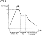
- the first thermal adhesive of the first portion 410 is melted once at a predetermined temperature (first melting temperature) Tml (see FIG. 7 ) higher than or equal to the first softening point, thereby hermetically bonding the first panel 20 and the second panel 30 together via the first portion 410.
- first melting temperature first melting temperature
- the second portion 420 of the thermal adhesive is disposed in the internal space 500.
- the second portion 420 partitions the internal space 500 into a hermetically sealed space, that is, a first space 510 serving as the evacuated space 50 hermetically closed when the glass panel unit 10 is completed and an evacuated space, that is, a second space 520 which is communicated with the evacuation port 700.
- the second portion 420 is formed such that the first space 510 is larger than the second space 520.
- the second portion 420 is disposed with a prescribed distance (e.g., 1 mm or 5 mm) from the first portion 410, and a portion between the first portion 410 and the second portion 420 serves as the evacuation path 600.
- the second portion 420 has part whose distance to the first portion 410 is larger than the prescribed distance, and the second space 520 is formed between the part and the first portion 410.
- the second portion 420 is made of a thermal adhesive (a second thermal adhesive having a second softening point).
- the second thermal adhesive is, for example, glass frit.
- the glass frit is, for example, low-melting-point glass frit. Examples of the low-melting-point glass frit include bismuth-based glass frit, lead-based glass frit, and vanadium-based glass frit.
- the second thermal adhesive is the same as the first thermal adhesive, and the second softening point is equal to the first softening point.
- the evacuation port 700 is a hole communicated with the second space 520 and an external space.
- the evacuation port 700 is used to evacuate the first space 510 through the second space 520 and the evacuation path 600.
- the evacuation port 700 is formed in the second panel 30 to be communicated with the second space 520 and the external space. Specifically, the evacuation port 700 is located at a corner of the second panel 30. Note that in the first embodiment, the evacuation port 700 is formed in the second panel 30, but the evacuation port 700 may be formed in the first panel 20 or the first portion 410.
- the gas adsorbent 60 is disposed in the first space 510.
- the gas adsorbent 60 has an elongated shape and is formed at an end in a longitudinal direction of the second panel 30 so as to extend along a short direction of the second panel 30. That is, the gas adsorbent 60 is disposed at an end of the first space 510 (evacuated space 50). In this way, the gas adsorbent 60 becomes less noticeable.
- the gas adsorbent 60 is located at a location away from the second portion 420 and the evacuation path 600. Thus, when the first space 510 is evacuated, it is possible to suppress the gas adsorbent 60 from hindering the evacuation.
- the gas adsorbent 60 is used to adsorb unnecessary gas (for example, remaining gas).
- the unnecessary gas is gas released from the first portion 410 and the second portion 420 when, for example, the first portion 410 and the second portion 420 are heated to the first melting temperature Tm1.
- the gas adsorbent 60 contains a getter.
- the getter is a material having a property of adsorbing molecules smaller than a prescribed size.
- the getter is, for example, an evaporable getter.
- the evaporable getter has a property of releasing adsorbed molecules at or higher than a predetermined temperature (activation temperature).
- activation temperature a predetermined temperature
- the evaporable getter is, for example, zeolite or ion-exchanged zeolite (e.g., copper ion-exchanged zeolite).
- the gas adsorbent 60 contains powder of the getter. Specifically, the gas adsorbent 60 is formed by application of a solution containing powder of a getter dispersed therein. In this case, the gas adsorbent 60 can be downsized. Thus, even when the evacuated space 50 is small, the gas adsorbent 60 can be disposed.
- the plurality of pillars 70 are used to maintain a prescribed space between the first panel 20 and the second panel 30. That is, the plurality of pillars 70 serve as spacers for maintaining the distance between the first panel 20 and the second panel 30 to have a desired value.
- the plurality of pillars 70 are disposed in the first space 510. Specifically, the plurality of pillars 70 are arranged at respective intersections of a rectangular (square or oblong) grid. For example, the interval between each two of the plurality of pillars 70 is 2 cm. Note that, sizes of the pillars 70, the number of the pillars 70, the interval between the pillars 70, and the arrangement pattern of the pillars 70 may be accordingly selected.
- Each pillar 70 is made of a transparent material. Note that each pillar 70 may be made of a non-transparent material as long as it is sufficiently small. Materials for the pillars 70 are selected in an internal space forming step described later such that the pillars 70 are not deformed. For example, materials for each pillar 70 are selected to have a softening point (softening temperature) higher than the first softening point of the first thermal adhesive and the second softening point of the second thermal adhesive.
- the temporary assembly 100 is subjected to the prescribed process to obtain the glass panel unit (finished product) 10.
- the first space 510 is evacuated at a predetermined temperature (exhaust temperature) Te (see FIG. 8 ) via a passage including the evacuation path 600, the second space 520, and the evacuation port 700 and allowing gas to be exhausted to the external space, thereby realizing the evacuated space 50 from the first space 510.
- the exhaust temperature Te is higher than the activation temperature of the getter in the gas adsorbent 60. This concurrently enables evacuation of the first space 510 and recovery of the adsorption capacity of the getter.
- the second portion 420 (see FIG. 4 ) is deformed to form a partition 42 that closes the evacuation path 600, thereby forming the seal 40 surrounding the evacuated space 50. Since the second portion 420 contains the second thermal adhesive, local heating is performed to once melt the second thermal adhesive to deform the second portion 420 so as to form the partition 42.
- the second portion 420 is deformed to close the evacuation path 600.
- the partition 42 obtained by thus deforming the second portion 420 spatially separates the evacuated space 50 from the second space 520.
- the seal 40 surrounding the evacuated space 50 is constituted by a portion 41 corresponding to the evacuated space 50 and the partition 42.
- the glass panel unit (finished product) 10 thus obtained includes the first panel 20, the second panel 30, the seal 40, the evacuated space 50, the second space 520, the gas adsorbent 60, the plurality of pillars 70, and the closing member 80.
- the evacuated space 50 is formed by evacuating the first space 510 through the second space 520 and the evacuation port 700.
- the evacuated space 50 is the first space 510 in which the degree of vacuum is lower than or equal to a prescribed value.
- the prescribed value is, for example, 0.1 Pa.
- the evacuated space 50 is fully hermetically sealed with the first panel 20, the second panel 30, and the seal 40 and is thus separated from the second space 520 and the evacuation port 700.
- the seal 40 fully surrounds the evacuated space 50 and hermetically bonds the first panel 20 and the second panel 30 together.
- the seal 40 has a frame shape and includes the portion 41 corresponding to the evacuated space 50 and the partition 42.
- the portion 41 corresponding to the evacuated space 50 is, in other words, a portion facing the evacuated space 50.
- the partition 42 is a partition obtained by deforming the second portion 420.
- the closing member 80 reduces objects such as dust entering through the evacuation port 700 into the second space 520.
- the closing member 80 is a cover 81 provided on a front side of the evacuation port 700 formed in the first panel 20 or the second panel 30.
- Providing the closing member 80 to the evacuation port 700 reduces objects such as dust entering through the evacuation port 700 into the second space 520. This reduces degradation of the appearance of the glass panel unit 10 due to objects such as dust entering through the evacuation port 700 into the second space 520. Note that the closing member 80 does not have to be provided.
- the method for manufacturing the glass panel unit 10 of the first embodiment includes at least an adhesive disposing step, a glass composite generation step, an internal space forming step, an evacuation step, and an evacuated space forming step. Note that another step may be optionally included. The steps will be described in order below.
- the substrate forming step is executed at first.
- the substrate forming step is a step of forming the first panel 20 and the second panel 30. Specifically, in the substrate forming step, for example, the first panel 20 and the second panel 30 are formed. Moreover, in the substrate forming step, the first panel 20 and the second panel 30 are washed as necessary.
- the evacuation port 700 is formed in the second panel 30.
- the evacuation port 700 may be formed in the first panel 20 or may be formed in the first portion 410 of the thermal adhesive. That is, the evacuation port 700 is formed in at least any one of the first panel 20, the second panel 30, or the first portion 410.
- the adhesive disposing step is a step of disposing the thermal adhesive (the first portion 410 and the second portion 420) on the first panel 20 or the second panel 30. Specifically, in the adhesive disposing step, the first portion 410 and the second portion 420 are formed on the second panel 30. In the adhesive disposing step, the material (first thermal adhesive) for the first portion 410 and a material (second thermal adhesive) for the second portion 420 are applied to the second panel 30 (the first surface of the second glass pane 31) with, for example, a dispenser.
- the material for the first portion 410 and the material for the second portion 420 may be dried and pre-sintered.
- the second panel 30, on which the material for the first portion 410 and the material for the second portion 420 have been applied is heated.
- the first panel 20 may be heated together with the second panel 30. That is, the first panel 20 may be heated under the same condition as the condition for the second panel 30.
- the difference between the warp of the first panel 20 and the warp of the second panel 30 can be reduced.
- the pillar forming step is performed. Specifically, in the pillar forming step, the plurality of pillars 70 are formed in advance, and the plurality of pillars 70 are arranged at respective prescribed positions on the second panel 30 with, for example, a chip mounter.
- the plurality of pillars 70 may be formed by a photolithography technique and an etching technique.
- the plurality of pillars 70 are made of, for example, a photocurable material.
- the plurality of pillars 70 may be formed by a well-known thin film forming technique.
- the gas adsorbent forming step is performed. Specifically, in the gas adsorbent forming step, a solution containing powder of the getter dispersed therein is applied to prescribed positions on the second panel 30 and is dried to form the gas adsorbent 60. Note that the order of the adhesive disposing step, the pillar forming step, and the gas adsorbent forming step is arbitrary.
- the glass composite generation step is a step of disposing the second panel 30 to face the first panel 20 to generate a glass composite.
- the glass composite includes the first panel 20, the second panel 30, and the thermal adhesive (the first portion 410 and the second portion 420).
- the first panel 20 and the second panel 30 are disposed and stacked on one another such that the first surface of the first glass pane 21 and the first surface of the second glass pane 31 are parallel to each other and face each other.
- the thermal adhesive is in contact with the first panel 20 and the second panel 30, thereby forming the glass composite.
- the glass composite has the evacuation port 700 and the evacuation path 600 located between the first portion 410 and the second portion 420 and extending to the evacuation port 700.
- the evacuation path 600 is communicated with the external space and the internal space 500 via the evacuation port 700. It is possible to vent between the external space and the internal space 500 via the evacuation path 600 and the evacuation port 700.
- the internal space forming step is a step of heating the glass composite to melt the thermal adhesive so as to form an internal space 500 surrounded by the first panel 20, the second panel 30, and a melted substance of the thermal adhesive except for the evacuation port 700.
- the first panel 20 and the second panel 30 are bonded together, thereby preparing the temporary assembly 100. That is, the internal space forming step is a step of hermetically bonding the first panel 20 and the second panel 30 together via the first portion 410 and the second portion 420.
- the first thermal adhesive is melted at a predetermined temperature (first melting temperature) Tml higher than or equal to the first softening point to hermetically bond the first panel 20 and the second panel 30 together.
- first melting temperature a predetermined temperature
- the glass composite is disposed in a melting furnace and are heated as illustrated in FIG. 7 , at the first melting temperature Tml for a predetermined time (first melting time) tm1.
- the first melting temperature Tml and the first melting time tm1 are determined such that the first panel 20 and the second panel 30 are hermetically bonded together via the first portion 410 and the second portion 420 but the evacuation path 600 is not closed with the second portion 420. That is, the lower limit of the first melting temperature Tml is the first softening point, but the upper limit of the first melting temperature Tml is determined such that the evacuation path 600 is not closed with the second portion 420. For example, when each of the first softening point and the second softening point is 290°C, the first melting temperature Tml is set to 300°C. Moreover, the first melting time tm1 is, for example, 10 minutes. Note that in the internal space forming step, gas is released from the first portion 410 and the second portion 420, but the gas is adsorbed on the gas adsorbent 60.
- the first portion 410 and the second portion 420 before being softened shown in FIGS. 9A and 9B are softened into a state shown in FIGS. 10A and 10B .
- the softened first portion 410 and second portion 420 bonds the first panel 20 and the second panel 30 together. In this way, the temporary assembly 100 shown in FIG. 8 is obtained.
- the evacuation step is a step of exhausting gas from the internal space 500 to evacuate the internal space 500.
- the evacuation step is a step of evacuating the first space 510 at a predetermined temperature (the exhaust temperature) Te through the evacuation path 600, the second space 520, and the evacuation port 700.
- the evacuation is performed with, for example, a vacuum pump.
- the vacuum pump is connected via an exhaust pipe 810 and a seal head 820 to the temporary assembly 100.
- the exhaust pipe 810 is bonded to the second panel 30, for example, such that the interior of the exhaust pipe 810 is in communication with the evacuation port 700.
- the seal head 820 is attached to the exhaust pipe 810, thereby connecting an inlet of the vacuum pump to the evacuation port 700.
- the exhaust pipe 810 is bonded to the second panel 30 at least before the internal space forming step.
- the first space 510 is evacuated at the exhaust temperature Te for a predetermined time (exhaust time) te through the evacuation path 600, the second space 520, and the evacuation port 700.
- the exhaust temperature Te is set to be higher than the activation temperature (e.g., 240°C) of the getter in the gas adsorbent 60 and lower than the first softening point and the second softening point (e.g., 290°C).
- the exhaust temperature Te is 250°C.
- the first portion 410 and the second portion 420 are not deformed.
- the getter in the gas adsorbent 60 is activated, and molecules (gas) adsorbed on the getter is released from the getter. Then, the molecules (i.e., gas) released from the getter is discharged through the first space 510, the evacuation path 600, the second space 520, and the evacuation port 700.
- the adsorption capacity of the gas adsorbent 60 is recovered.
- the exhaust time te is set such that the evacuated space 50 having a desired degree of vacuum (e.g., degree of vacuum of lower than or equal to 0.1 Pa). For example, the exhaust time te is set to 120 minutes.
- the reduced-pressure space forming step is a step of sealing the internal space 500 to form the evacuated space 50 hermetically closed.
- part of at least one of the first portion 410 or the second portion 420 is heated and force is applied to deform the part, thereby closing the evacuation path 600.
- the evacuated space forming step is a step of deforming the first portion 410 to close the evacuation path 600 to form the partition 42 (see FIG. 2 ) surrounding the evacuated space 50.
- the first portion 410 is locally heated to a predetermined temperature (second melting temperature) higher than or equal to the second softening point.
- a predetermined temperature second melting temperature
- an irradiator configured to output a laser beam is used.
- the irradiator is configured to externally irradiate the first portion 410 with a laser beam through the second panel 30.
- a device other than the irradiator may be used, and a method for performing the local heating is not limited.
- exhaustion with a vacuum pump similar to the exhaustion performed in the evacuation step is continued also in the evacuated space forming step. Note that in the evacuated space forming step, the exhaustion with a vacuum pump similar to the exhaustion performed in the evacuation step does not have to be continued, but the degree of vacuum is at least maintained.
- the first portion 410 When from a state shown in FIGS. 10A and 10B , the first portion 410 is heated to a temperature higher than or equal to the first softening point, the first portion 410 is softened and becomes easy to deform.
- a jig 830 is inserted between the first panel 20 and the second panel 30.
- the jig 830 pushes the first portion 410 toward the second portion 420, the first portion 410 comes into contact with the second portion 420, thereby forming a closed part 480 that closes the evacuation path 600.
- the internal space 500 is sealed, and the evacuated space 50 hermetically closed is formed.
- the quantity of gas released is less than that in a case where the entirety of the first portion 410 and the second portion 420 are heated and unnecessary gas is released from the entirety of the first portion 410 and the second portion 420.
- it becomes easy to improve the degree of vacuum of the evacuated space 50 that is, to reduce the pressure in the evacuated space 50).
- the jig 830 applies force to part of the first portion 410 to deform the first portion 410.
- force resulting from atmospheric pressure may be applied to part of the first portion 410 or the second portion 420 without using the jig 830 to deform the part to close the evacuation path 600.
- the jig 830 is no longer necessary, and the evacuated space forming step is performable with a simple configuration.
- FIGS. 12 , 13A, 13B, and 13C a method for manufacturing a glass panel unit 10 according to a second embodiment will be described with reference to FIGS. 12 , 13A, 13B, and 13C .
- the method for manufacturing the glass panel unit 10 of the second embodiment is for the most part the same as the method for manufacturing the glass panel unit 10 of the first embodiment.
- description similar to the description in the first embodiment is omitted, and differences are mainly described.
- a glass composite has one or a plurality of ventilation path 610 between a first portion 410 and a third portion 430 of a thermal adhesive.
- an evacuated space forming step part of at least any one of the first portion 410 or the third portion 430 is heated, and force is applied to the part to deform the part, thereby closing the ventilation path 610 as illustrated in FIG. 13B .
- an internal space 500 is divided into a plurality of evacuated spaces 50.
- the first portion 410, a second portion 420, and the third portion 430 of the thermal adhesive are disposed as illustrated in FIG. 12 .
- part of the first portion 410 is locally heated, and force resulting from atmospheric pressure is applied to the part.
- the part of the first portion 410 is deformed to form a closed part 490 to close an evacuation path 600.
- the internal space 500 may be divided into the plurality of evacuated spaces 50, and a plurality of glass panel units 10 each having the evacuated space 50 is obtainable from one glass panel unit 10..
- the third portion 430 may be locally heated. In this case, as illustrated in FIG. 13C , part of the third portion 430 is deformed to form the closed part 490 to close the evacuation path 600.
- the glass panel unit 10 according to the third embodiment includes components in addition to the components in the first embodiment or the second embodiment.
- the method for manufacturing the glass panel unit 10 of the third embodiment further includes a second internal space forming step.
- the second internal space forming step includes disposing: a third panel 90 including a third glass pane 91 and; a third thermal adhesive between the third panel 90 and either a first panel 20 or a second panel 30. Then, in the second internal space forming step, a second internal space 540 surrounded by the third panel 90, the first panel 20 or the second panel 30, and the third thermal adhesive is formed.
- the glass panel unit 10 of the third embodiment includes the third panel 90 disposed to face the second panel 30.
- the third panel 90 faces, for the sake of convenience, the second panel 30 but may face the first panel 20.
- the third panel 90 includes a third glass pane 91.
- the third glass pane 91 included in the third panel 90 has a flat surface and a predetermined thickness.
- the third glass pane 91 constitutes the third panel 90.
- a coating may be provided on any one of surfaces of the third panel 90.
- the coating is a film such as an infrared reflective film having a desired physical property.
- the third panel 90 includes the third glass pane 91 and the coating.
- the third panel 90 includes the third glass pane 91.
- the glass panel unit 10 includes a second seal 43 disposed between the second panel 30 and the third panel 90 to hermetically bond the second panel 30 and the third panel 90 together.
- a seal 40 is a first seal.
- the second seal 43 is disposed to have an annular shape between a peripheral portion of the second panel 30 and a peripheral portion of the third panel 90.
- the second seal 43 may be made of a material similar to or different from that for the seal 40.
- the glass panel unit 10 has the second internal space 540 surrounded by and hermetically closed with the second panel 30, the third panel 90, and the second seal 43 and filled with a drying gas.
- an internal space 500 is a first internal space.
- a noble gas such as argon, dry air, or the like is used but is not limited to this example.
- a frame member 92 having a hollow is disposed to have an annular shape.
- the frame member 92 has a through hole 921 which is in communication with the second internal space 540 and in which desiccant 93 such as silica gel is accommodated.
- the second panel 30 and the third panel 90 may be bonded together in a similar manner to bonding of the first panel 20 and the second panel 30 together.
- An example of the second internal space forming step will be described below.
- the third panel 90 and an assembly element including the first panel 20 and the second panel 30 are prepared.
- the third thermal adhesive which is to serve as the second seal 43 later is disposed.
- the third thermal adhesive is disposed on a peripheral portion of a surface of the third panel 90 or the second panel 30 (second thermal adhesive disposing step).
- Third thermal adhesive may be made of a material similar to or different from a thermal adhesive (first thermal adhesive) which is to serve as a first portion 410.
- an evacuation path (second evacuation path) as a through hole through which the second internal space 540 and the external space are communicated with each other is formed in the third thermal adhesive.
- the third panel 90 and the second panel 30 are disposed to face each other (third panel opposite disposition step).
- a temperature is increased to a melting temperature of the thermal adhesive which is to serve as the second seal 43 to once melt the thermal adhesive, thereby hermetically bonding the second panel 30 and the third panel 90 together via the second seal 43 (bonding step). Note that at this time, the second evacuation path is not fully closed.
- drying gas feeding step a drying gas is introduced into the second internal space 540 through the second evacuation path.
- the second internal space 540 may be fully filled with only the drying gas, or air may be left in the second internal space 540. Note that the drying gas feeding step may be omitted.
- the second seal 43 is heated to close the second evacuation path so as to seal up the second internal space 540 (second space sealing step).
- second space sealing step ends.
- the glass panel unit 10 is formed.
- the glass panel unit 10 of the third embodiment provides a further improved thermal insulation property.
- the fourth embodiment is a glass window 95 including the glass panel unit 10 of any one of the first to third embodiments.
- a glass panel unit 10 similar to that of any of the first to third embodiments is used.
- the method for manufacturing the glass window 95 in the fourth embodiment further includes a step of fitting the glass panel unit 10 manufactured in any of the first to third embodiments in a window frame 96 to manufacture the glass window 95.
- the peripheral portion of the glass panel unit 10 is fit in the window frame 96 having a U-shaped cross section, thereby forming the glass window 95.
- the glass window 95 of the fourth embodiment provides a further improved thermal insulation property.
- the glass panel unit 10 has a rectangular shape, but the glass panel unit 10 may have a desired shape such as a round shape or a polygonal shape. That is, the first panel 20, the second panel 30, and the seal 40 do not have to have a rectangular shape but may have a desired shape such as a round shape or a polygonal shape.
- the shape of each of the first panel 20, the second panel 30, the portion 41 corresponding to the evacuated space 50, and the partition wall 42 is not limited to the shape in the embodiments but may be a shape that provides a glass panel unit 10 having a desired shape. Note that the shape or the size of the glass panel unit 10 is determined based on the application of the glass panel unit 10.
- first surface and the second surface of the first glass pane 21 of the first pane 20 are not limited to flat surfaces.
- first surface and the second surface of the second glass pane 31 of the second panel 30 are not limited to flat surfaces.
- first glass pane 21 of the first panel 20 and the second glass pane 31 of the second panel 30 do not have to have the same planar shape and the same flat surface size. Further, the first glass pane 21 and the second glass pane 31 do not have to have the same thickness. Furthermore, the first glass pane 21 and the second glass pane 31 do not have to be made of the same material.
- the first panel 20 may further include a coating having a desired physical property and formed on the second surface of the first glass pane 21.
- the first panel 20 does not have to be provided with the coating 22. That is, the first panel 20 may include only the first glass pane 21.
- the second panel 30 may further include a coating having a desired physical property.
- the coating includes at least one of thin films formed on the first surface and the second surface of, for example, the second glass pane 31.
- Examples of the coating include an infrared reflective film and an ultraviolet reflecting film which reflect light having a prescribed wavelength.
- the internal space 500 is partitioned into one first space 510 and one second space 520.
- the internal space 500 may be partitioned into one or more first spaces 510 and one or more second spaces 520.
- the second thermal adhesive is the same as the first thermal adhesive, and the second softening point is equal to the first softening point.
- the second thermal adhesive may be a material different from the first thermal adhesive.
- the second thermal adhesive may have a second softening point different from the first softening point of the first thermal adhesive.
- first adhesive and the second thermal adhesive are not limited to the glass frit but may be, for example, low-melting-point metal or a hot-melt adhesive material.
- a method for manufacturing a glass panel unit 10 of a first aspect includes an adhesive disposing step, a glass composite generation step, an internal space forming step, an evacuation step, and an evacuated space forming step.
- the adhesive disposing step is a step of disposing a thermal adhesive on a first panel 20 or a second panel 30.
- the glass composite generation step is a step of disposing the second panel 30 to face the first panel 20 to generate a glass composite including the first panel 20, the second panel 30, and the thermal adhesive.
- the glass composite has an evacuation port 700 and an evacuation path 600.
- the evacuation port 700 is formed in at least any one of the first panel 20, the second panel 30, or a first portion 410 of the thermal adhesive which is to serve as a seal 40 later.
- the evacuation path 600 is located between the first portion 410 and a second portion 420 of the thermal adhesive and extends to the evacuation port 700.
- the internal space forming step is a step of heating the glass composite to melt the thermal adhesive so as to form an internal space 500 surrounded by the first panel 20, the second panel 30, and a melted substance of the thermal adhesive except for the evacuation port 700.
- the evacuation step is a step of exhausting gas from the internal space 500 to evacuate the internal space 500.
- the evacuated space forming step is a step of, while the internal space is kept in an evacuated state, heating and applying force to part of at least the first portion 410 or the second portion 420 to deform the part to close the evacuation path 600 such that the internal space 500 is sealed to form an evacuated space 50 hermetically closed.
- gas released from the thermal adhesive (the first portion 410 and the second portion 420) is less than unnecessary gas released from the entirety of the first portion 410 and the second portion 420 when the entirety of the first portion 410 and the second portion 420 are heated in the evacuated space forming step.
- a method for manufacturing a glass panel unit 10 of a second aspect according to the present disclosure is realized in combination with the first aspect.
- the evacuated space forming step includes applying force resulting from atmospheric pressure to part of the first portion 410 or the second portion 420 to deform the part of the first portion 410 or the second portion 420 to close the evacuation path 600.
- the method for manufacturing the glass panel unit 10 of the second aspect requires no jig 830 and enables a simple configuration to perform the evacuated space forming step.
- a method for manufacturing a glass panel unit 10 of a third aspect according to the present disclosure is realized in combination with the first or second aspect.
- the glass composite has one or more ventilation paths 610 between the first portion 410 and a third portion 430 of the thermal adhesive.
- the evacuated space forming step includes heating and applying force to part of at least the first portion 410 or the third portion 430 to deform the part of at least the first portion 410 or the third portion 430 to close the ventilation path 610 such that the internal space 500 is divided into a plurality of evacuated spaces 50.
- a plurality of glass panel units 10 each having the evacuated space 50 is obtainable from one glass panel unit 10.
- a method for manufacturing a glass panel unit 10 of a fourth aspect according to the present disclosure is realized in combination with any one of the first to third aspects.
- the method for manufacturing the glass panel unit 10 of the fourth aspect further includes a second internal space forming step.
- the second internal space forming step includes disposing: a third panel 90; and a third thermal adhesive between a third panel 90 and either the first panel 20 or the second panel 30.
- a second internal space 540 surrounded by the third panel 90, the first panel 20 or the second panel 30, and the third thermal adhesive is formed.
- the method for manufacturing the glass panel unit 10 of the fourth aspect enables a glass panel unit 10 having further improved thermal insulation properties to be manufactured.
- a method for manufacturing a glass window 95 of a fifth aspect includes a step of fitting the glass panel unit 10 manufactured by the method of any one of the first to fourth aspects into a window frame 96 to manufacture a glass window 95.
- the manufacturing method of the glass window 95 of the fifth aspect enables a glass window 95 having further improved thermal insulation properties to be manufactured.
Landscapes
- Engineering & Computer Science (AREA)
- Chemical & Material Sciences (AREA)
- Civil Engineering (AREA)
- Structural Engineering (AREA)
- Geochemistry & Mineralogy (AREA)
- Organic Chemistry (AREA)
- Materials Engineering (AREA)
- Life Sciences & Earth Sciences (AREA)
- Chemical Kinetics & Catalysis (AREA)
- General Chemical & Material Sciences (AREA)
- Ceramic Engineering (AREA)
- Thermal Sciences (AREA)
- Physics & Mathematics (AREA)
- Securing Of Glass Panes Or The Like (AREA)
- Joining Of Glass To Other Materials (AREA)
Abstract

Description
- The present invention relates to a method for manufacturing a glass panel unit and a method for manufacturing a glass window.
-
Patent Literature 1 discloses an insulated glazing including a pair of flat glass panes facing each other with a prescribed distance therebetween and a method for manufacturing the insulated glazing. - The method for manufacturing the insulated glazing disclosed in
Patent Literature 1 includes a first melting step of achieving a temperature higher than or equal to a softening point temperature of glass frit contained in a frit seal and a partition. In this way, peripheral portions of the pair of flat glass panes are sealed together, thereby forming a space which is hermetically closable. The space is evacuated, and then, a second melting step is performed to heat the pair of flat glass panes and the glass frit, thereby sealing an evacuation port. - Since the method for manufacturing the insulated glazing disclosed in
Patent Literature 1 heats the pair of flat glass panes and the entirety of the glass frit in the second melting step, a large quantity of unnecessary gas is released from the entirety of the glass frit, which may lower the degree of vacuum of the space. - Patent Literature 1:
JP 2015-147727 A - One of the objectives of the present disclosure is to provide a method for manufacturing a glass panel unit which releases a reduced quantity of unnecessary gas and a method for manufacturing a glass window.
- A method for manufacturing a glass panel unit of one aspect of the present disclosure includes: an adhesive disposing step, a glass composite generation step, an internal space forming step, an evacuation step, and an evacuated space forming step. The adhesive disposing step is a step of disposing a thermal adhesive on a first panel or a second panel. The glass composite generation step is a step of disposing the second panel to face the first panel to generate a glass composite including the first panel, the second panel, and the thermal adhesive. The glass composite has an evacuation port and an evacuation path. The evacuation port is formed in at least any one of the first panel, the second panel, or a first portion of the thermal adhesive which is to serve as a seal later. The evacuation path is located between the first portion and a second portion of the thermal adhesive and extends to the evacuation port. The internal space forming step is a step of heating the glass composite to melt the thermal adhesive to form an internal space surrounded by the first panel, the second panel, and a melted substance of the thermal adhesive except for the evacuation port. The evacuation step is a step of exhausting gas from the internal space to evacuate the internal space. The evacuated space forming step is a step of, while the internal space is kept in an evacuated state, heating and applying force to part of at least the first portion or the second portion to deform the part to close the evacuation path such that the internal space is sealed to form an evacuated space hermetically closed.
- A manufacturing method of a glass window according to the present disclosure includes a step of fitting the glass panel unit manufactured by the method of the one aspect in a window frame to manufacture a glass window.
-
-
FIG. 1 is a vertical sectional view schematically illustrating a glass panel unit of a first embodiment; -
FIG. 2 is a partially cutaway plan view schematically illustrating the glass panel unit; -
FIG. 3 is a vertical sectional view schematically illustrating a temporary assembly of the glass panel unit; -
FIG. 4 is a partially cutaway plan view schematically illustrating the temporary assembly; -
FIG. 5 is a view illustrating a method for manufacturing the glass panel unit; -
FIG. 6 is a view illustrating the method for manufacturing the glass panel unit; -
FIG. 7 is a view illustrating a temperature change in the method for manufacturing the glass panel unit; -
FIG. 8 is a view illustrating the method for manufacturing the glass panel unit; -
FIG. 9A is a horizontal sectional view of a main part of the glass panel unit, the horizontal sectional view illustrating an evacuated space forming step in the method for manufacturing the glass panel unit, andFIG. 9B is a vertical sectional view of the main part, the vertical sectional view illustrating the evacuated space forming step; -
FIG. 10A is a horizontal sectional view of the main part, the horizontal sectional view illustrating the evacuated space forming step, andFIG. 10B is a vertical sectional view of the main part, the vertical sectional view illustrating the evacuated space forming step; -
FIG. 11A is a horizontal sectional view of the main part, the horizontal sectional view illustrating the evacuated space forming step, andFIG. 11B is a vertical sectional view of the main part, the vertical sectional view illustrating the evacuated space forming step; -
FIG. 12 is a plan view schematically illustrating a glass panel unit of a second embodiment; -
FIG. 13A is a vertical sectional view illustrating a main part of the glass panel unit, the vertical sectional view illustrating an evacuated space forming step in a method for manufacturing the glass panel unit of the second embodiment,FIG. 13B is a vertical sectional view of the main part, the vertical sectional view illustrating the evacuated space forming step, andFIG. 13C is a vertical sectional view illustrating the main part, the vertical sectional view illustrating a variation of the evacuated space forming step; -
FIG. 14 is a vertical sectional view schematically illustrating a glass panel unit of a third embodiment of the present invention; -
FIG. 15 is a partially cutaway plan view schematically illustrating the glass panel unit of the third embodiment; and -
FIG. 16 is a plan view schematically illustrating a glass window including a glass panel unit of a fourth embodiment of the present invention. - First to fourth embodiments below relate to a glass panel unit (the fourth embodiment further relates to a glass window). In particular, the first to fourth embodiments relate to a glass panel unit including a first panel, a second panel disposed to face the first panel with a prescribed distance from the first panel, and a seal disposed between the first panel and the second panel to hermetically bond the first panel and the second panel together.
-
FIGS. 1 and2 show aglass panel unit 10 of the first embodiment (finished product of a glass panel unit). Theglass panel unit 10 of the first embodiment is a vacuum insulating glass unit. The vacuum insulating glass unit is a type of insulated glazing panels including at least a pair of glass panels and includes an evacuated space (or vacuum space) between the pair of glass panels. - The
glass panel unit 10 of the first embodiment includes afirst panel 20, asecond panel 30, aseal 40, an evacuatedspace 50, a gas adsorbent 60, a plurality ofpillars 70, and aclosing member 80. - The glass panel unit (finished product) 10 is obtained by performing a prescribed process on a
temporary assembly 100 shown inFIGS. 3 and4 . - The
temporary assembly 100 includes thefirst panel 20, thesecond panel 30, afirst portion 410 of a thermal adhesive, aninternal space 500, asecond portion 420 of the thermal adhesive, anevacuation path 600, anevacuation port 700, the gas adsorbent 60, and a plurality ofpillars 70. - The
first panel 20 includes afirst glass pane 21 and acoating 22. Thefirst glass pane 21 defines the planar shape of thefirst panel 20. - The
first glass pane 21 is a rectangular flat plate and has a first surface (a lower surface inFIG. 3 ) and a second surface (an upper surface inFIG. 3 ) which are parallel to each other on both sides in a thickness direction of the first glass pane. The first surface and the second surface of thefirst glass pane 21 are flat surfaces. Examples of materials for thefirst glass pane 21 include soda-lime glass, high strain-point glass, chemically tempered glass, no-alkali glass, quartz glass, Neoceram, and physically tempered glass. - The
coating 22 is formed on the first flat surface of thefirst glass pane 21. Thecoating 22 is an infrared reflective film. Note that thecoating 22 is not limited to the infrared reflective film but may be a film having a desired physical property. Note that thefirst panel 20 may include only thefirst glass pane 21. In sum, thefirst panel 20 includes thefirst glass pane 21. - The
second panel 30 includes asecond glass pane 31 which defines the planar shape of thesecond panel 30. Thesecond glass pane 31 is a rectangular flat plate and has a first surface (un upper surface inFIG. 3 ) and a second surface (a lower surface inFIG. 3 ) which are parallel to each other on both sides in a thickness direction of the second glass pane. The first surface and the second surface of thesecond glass pane 31 are flat surfaces. - The planar shape and the flat surface size of the
second glass pane 31 are the same as those of the first glass pane 21 (that is, the planar shape of thesecond panel 30 is the same as that of the first panel 20). Moreover, the thickness of thesecond glass pane 31 is the same as that of, for example, thefirst glass pane 21. Examples of materials for thesecond glass pane 31 include soda-lime glass, high strain-point glass, chemically tempered glass, no-alkali glass, quartz glass, Neoceram, and physically tempered glass. - The
second panel 30 includes only thesecond glass pane 31. That is, thesecond glass pane 31 is thesecond panel 30 itself: Note that a coating may be provided on any one of surfaces of thesecond panel 30. The coating is a film such as an infrared reflective film having a desired physical property. In this case, thesecond panel 30 includes thesecond glass pane 31 and the coating. In sum, thesecond panel 30 includes thesecond glass pane 31. - The
second panel 30 is disposed to face thefirst panel 20. Specifically, thefirst panel 20 and thesecond panel 30 are disposed such that the first surface of thefirst glass pane 21 and the first surface of thesecond glass pane 31 are parallel to each other and face each other. - As illustrated in
FIG. 3 , thefirst portion 410 of the thermal adhesive is disposed between thefirst panel 20 and thesecond panel 30 to hermetically bond thefirst panel 20 and thesecond panel 30 together. Thus, theinternal space 500 surrounded by thefirst portion 410, thefirst panel 20, and thesecond panel 30 is formed. - The
first portion 410 is made of a thermal adhesive (a first thermal adhesive having a first softening point). The first thermal adhesive is, for example, glass frit. The glass frit is, for example, low-melting-point glass frit. Examples of the low-melting-point glass frit include bismuth-based glass frit, lead-based glass frit, and vanadium-based glass frit. - As illustrated in
FIG. 4 , thefirst portion 410 is disposed to have a rectangular frame shape in plan view. Thefirst portion 410 is smaller than each of thefirst glass pane 21 and thesecond glass pane 31 in plan view. Thefirst portion 410 is formed along an outer periphery of an upper surface of the second panel 30 (the first surface of the second glass pane 31). That is, thefirst portion 410 is formed to surround almost all area on the second panel 30 (the first surface of the second glass panel 31). - The first thermal adhesive of the
first portion 410 is melted once at a predetermined temperature (first melting temperature) Tml (seeFIG. 7 ) higher than or equal to the first softening point, thereby hermetically bonding thefirst panel 20 and thesecond panel 30 together via thefirst portion 410. - The
second portion 420 of the thermal adhesive is disposed in theinternal space 500. Thesecond portion 420 partitions theinternal space 500 into a hermetically sealed space, that is, afirst space 510 serving as the evacuatedspace 50 hermetically closed when theglass panel unit 10 is completed and an evacuated space, that is, asecond space 520 which is communicated with theevacuation port 700. Thesecond portion 420 is formed such that thefirst space 510 is larger than thesecond space 520. Thesecond portion 420 is disposed with a prescribed distance (e.g., 1 mm or 5 mm) from thefirst portion 410, and a portion between thefirst portion 410 and thesecond portion 420 serves as theevacuation path 600. Moreover, thesecond portion 420 has part whose distance to thefirst portion 410 is larger than the prescribed distance, and thesecond space 520 is formed between the part and thefirst portion 410. - The
second portion 420 is made of a thermal adhesive (a second thermal adhesive having a second softening point). The second thermal adhesive is, for example, glass frit. The glass frit is, for example, low-melting-point glass frit. Examples of the low-melting-point glass frit include bismuth-based glass frit, lead-based glass frit, and vanadium-based glass frit. The second thermal adhesive is the same as the first thermal adhesive, and the second softening point is equal to the first softening point. - The
evacuation port 700 is a hole communicated with thesecond space 520 and an external space. Theevacuation port 700 is used to evacuate thefirst space 510 through thesecond space 520 and theevacuation path 600. Theevacuation port 700 is formed in thesecond panel 30 to be communicated with thesecond space 520 and the external space. Specifically, theevacuation port 700 is located at a corner of thesecond panel 30. Note that in the first embodiment, theevacuation port 700 is formed in thesecond panel 30, but theevacuation port 700 may be formed in thefirst panel 20 or thefirst portion 410. - The
gas adsorbent 60 is disposed in thefirst space 510. Specifically, thegas adsorbent 60 has an elongated shape and is formed at an end in a longitudinal direction of thesecond panel 30 so as to extend along a short direction of thesecond panel 30. That is, thegas adsorbent 60 is disposed at an end of the first space 510 (evacuated space 50). In this way, thegas adsorbent 60 becomes less noticeable. Moreover, thegas adsorbent 60 is located at a location away from thesecond portion 420 and theevacuation path 600. Thus, when thefirst space 510 is evacuated, it is possible to suppress thegas adsorbent 60 from hindering the evacuation. - The
gas adsorbent 60 is used to adsorb unnecessary gas (for example, remaining gas). The unnecessary gas is gas released from thefirst portion 410 and thesecond portion 420 when, for example, thefirst portion 410 and thesecond portion 420 are heated to the first melting temperature Tm1. - The
gas adsorbent 60 contains a getter. The getter is a material having a property of adsorbing molecules smaller than a prescribed size. The getter is, for example, an evaporable getter. The evaporable getter has a property of releasing adsorbed molecules at or higher than a predetermined temperature (activation temperature). Thus, even when the adsorption capacity of the evaporable getter decreases, heating the evaporable getter to or higher than the activation temperature enables the adsorption capacity of the evaporable getter to be recovered. The evaporable getter is, for example, zeolite or ion-exchanged zeolite (e.g., copper ion-exchanged zeolite). - The
gas adsorbent 60 contains powder of the getter. Specifically, thegas adsorbent 60 is formed by application of a solution containing powder of a getter dispersed therein. In this case, thegas adsorbent 60 can be downsized. Thus, even when the evacuatedspace 50 is small, thegas adsorbent 60 can be disposed. - The plurality of
pillars 70 are used to maintain a prescribed space between thefirst panel 20 and thesecond panel 30. That is, the plurality ofpillars 70 serve as spacers for maintaining the distance between thefirst panel 20 and thesecond panel 30 to have a desired value. - The plurality of
pillars 70 are disposed in thefirst space 510. Specifically, the plurality ofpillars 70 are arranged at respective intersections of a rectangular (square or oblong) grid. For example, the interval between each two of the plurality ofpillars 70 is 2 cm. Note that, sizes of thepillars 70, the number of thepillars 70, the interval between thepillars 70, and the arrangement pattern of thepillars 70 may be accordingly selected. - Each
pillar 70 is made of a transparent material. Note that eachpillar 70 may be made of a non-transparent material as long as it is sufficiently small. Materials for thepillars 70 are selected in an internal space forming step described later such that thepillars 70 are not deformed. For example, materials for eachpillar 70 are selected to have a softening point (softening temperature) higher than the first softening point of the first thermal adhesive and the second softening point of the second thermal adhesive. - The
temporary assembly 100 is subjected to the prescribed process to obtain the glass panel unit (finished product) 10. - In the prescribed process, the
first space 510 is evacuated at a predetermined temperature (exhaust temperature) Te (seeFIG. 8 ) via a passage including theevacuation path 600, thesecond space 520, and theevacuation port 700 and allowing gas to be exhausted to the external space, thereby realizing the evacuatedspace 50 from thefirst space 510. The exhaust temperature Te is higher than the activation temperature of the getter in thegas adsorbent 60. This concurrently enables evacuation of thefirst space 510 and recovery of the adsorption capacity of the getter. - Moreover, in the prescribed process, as illustrated in
FIG. 2 , the second portion 420 (seeFIG. 4 ) is deformed to form apartition 42 that closes theevacuation path 600, thereby forming theseal 40 surrounding the evacuatedspace 50. Since thesecond portion 420 contains the second thermal adhesive, local heating is performed to once melt the second thermal adhesive to deform thesecond portion 420 so as to form thepartition 42. - As illustrated in
FIG. 2 , thesecond portion 420 is deformed to close theevacuation path 600. Thepartition 42 obtained by thus deforming thesecond portion 420 spatially separates the evacuatedspace 50 from thesecond space 520. Theseal 40 surrounding the evacuatedspace 50 is constituted by aportion 41 corresponding to the evacuatedspace 50 and thepartition 42. - As illustrated in
FIG. 2 , the glass panel unit (finished product) 10 thus obtained includes thefirst panel 20, thesecond panel 30, theseal 40, the evacuatedspace 50, thesecond space 520, thegas adsorbent 60, the plurality ofpillars 70, and the closingmember 80. - As described above, the evacuated
space 50 is formed by evacuating thefirst space 510 through thesecond space 520 and theevacuation port 700. In other words, the evacuatedspace 50 is thefirst space 510 in which the degree of vacuum is lower than or equal to a prescribed value. The prescribed value is, for example, 0.1 Pa. The evacuatedspace 50 is fully hermetically sealed with thefirst panel 20, thesecond panel 30, and theseal 40 and is thus separated from thesecond space 520 and theevacuation port 700. - The
seal 40 fully surrounds the evacuatedspace 50 and hermetically bonds thefirst panel 20 and thesecond panel 30 together. Theseal 40 has a frame shape and includes theportion 41 corresponding to the evacuatedspace 50 and thepartition 42. Theportion 41 corresponding to the evacuatedspace 50 is, in other words, a portion facing the evacuatedspace 50. Thepartition 42 is a partition obtained by deforming thesecond portion 420. - The closing
member 80 reduces objects such as dust entering through theevacuation port 700 into thesecond space 520. In the first embodiment, the closingmember 80 is acover 81 provided on a front side of theevacuation port 700 formed in thefirst panel 20 or thesecond panel 30. - Providing the closing
member 80 to theevacuation port 700 reduces objects such as dust entering through theevacuation port 700 into thesecond space 520. This reduces degradation of the appearance of theglass panel unit 10 due to objects such as dust entering through theevacuation port 700 into thesecond space 520. Note that the closingmember 80 does not have to be provided. - Next, a method for manufacturing the
glass panel unit 10 according to the first embodiment will be described with reference toFIGS. 5 and8 . - The method for manufacturing the
glass panel unit 10 of the first embodiment includes at least an adhesive disposing step, a glass composite generation step, an internal space forming step, an evacuation step, and an evacuated space forming step. Note that another step may be optionally included. The steps will be described in order below. - Although not shown in the figure, in the first embodiment, the substrate forming step is executed at first. The substrate forming step is a step of forming the
first panel 20 and thesecond panel 30. Specifically, in the substrate forming step, for example, thefirst panel 20 and thesecond panel 30 are formed. Moreover, in the substrate forming step, thefirst panel 20 and thesecond panel 30 are washed as necessary. - Next, a step of forming the
evacuation port 700 is performed. In this step, theevacuation port 700 is formed in thesecond panel 30. Note that theevacuation port 700 may be formed in thefirst panel 20 or may be formed in thefirst portion 410 of the thermal adhesive. That is, theevacuation port 700 is formed in at least any one of thefirst panel 20, thesecond panel 30, or thefirst portion 410. - Next, as illustrated in
FIG. 5 , the adhesive disposing step is performed. The adhesive disposing step is a step of disposing the thermal adhesive (thefirst portion 410 and the second portion 420) on thefirst panel 20 or thesecond panel 30. Specifically, in the adhesive disposing step, thefirst portion 410 and thesecond portion 420 are formed on thesecond panel 30. In the adhesive disposing step, the material (first thermal adhesive) for thefirst portion 410 and a material (second thermal adhesive) for thesecond portion 420 are applied to the second panel 30 (the first surface of the second glass pane 31) with, for example, a dispenser. - Note that in the adhesive disposing step, the material for the
first portion 410 and the material for thesecond portion 420 may be dried and pre-sintered. For example, thesecond panel 30, on which the material for thefirst portion 410 and the material for thesecond portion 420 have been applied, is heated. Note that thefirst panel 20 may be heated together with thesecond panel 30. That is, thefirst panel 20 may be heated under the same condition as the condition for thesecond panel 30. Thus, the difference between the warp of thefirst panel 20 and the warp of thesecond panel 30 can be reduced. - Next, the pillar forming step is performed. Specifically, in the pillar forming step, the plurality of
pillars 70 are formed in advance, and the plurality ofpillars 70 are arranged at respective prescribed positions on thesecond panel 30 with, for example, a chip mounter. Note that the plurality ofpillars 70 may be formed by a photolithography technique and an etching technique. In this case, the plurality ofpillars 70 are made of, for example, a photocurable material. Alternatively, the plurality ofpillars 70 may be formed by a well-known thin film forming technique. - Next, the gas adsorbent forming step is performed. Specifically, in the gas adsorbent forming step, a solution containing powder of the getter dispersed therein is applied to prescribed positions on the
second panel 30 and is dried to form thegas adsorbent 60. Note that the order of the adhesive disposing step, the pillar forming step, and the gas adsorbent forming step is arbitrary. - Next, the glass composite generation step is performed. As illustrated in
FIG. 6 , the glass composite generation step is a step of disposing thesecond panel 30 to face thefirst panel 20 to generate a glass composite. The glass composite includes thefirst panel 20, thesecond panel 30, and the thermal adhesive (thefirst portion 410 and the second portion 420). - The
first panel 20 and thesecond panel 30 are disposed and stacked on one another such that the first surface of thefirst glass pane 21 and the first surface of thesecond glass pane 31 are parallel to each other and face each other. The thermal adhesive is in contact with thefirst panel 20 and thesecond panel 30, thereby forming the glass composite. - The glass composite has the
evacuation port 700 and theevacuation path 600 located between thefirst portion 410 and thesecond portion 420 and extending to theevacuation port 700. Theevacuation path 600 is communicated with the external space and theinternal space 500 via theevacuation port 700. It is possible to vent between the external space and theinternal space 500 via theevacuation path 600 and theevacuation port 700. - Next, the internal space forming step is performed. The internal space forming step is a step of heating the glass composite to melt the thermal adhesive so as to form an
internal space 500 surrounded by thefirst panel 20, thesecond panel 30, and a melted substance of the thermal adhesive except for theevacuation port 700. Specifically, in the internal space forming step, thefirst panel 20 and thesecond panel 30 are bonded together, thereby preparing thetemporary assembly 100. That is, the internal space forming step is a step of hermetically bonding thefirst panel 20 and thesecond panel 30 together via thefirst portion 410 and thesecond portion 420. - In the internal space forming step, the first thermal adhesive is melted at a predetermined temperature (first melting temperature) Tml higher than or equal to the first softening point to hermetically bond the
first panel 20 and thesecond panel 30 together. Specifically, the glass composite is disposed in a melting furnace and are heated as illustrated inFIG. 7 , at the first melting temperature Tml for a predetermined time (first melting time) tm1. - The first melting temperature Tml and the first melting time tm1 are determined such that the
first panel 20 and thesecond panel 30 are hermetically bonded together via thefirst portion 410 and thesecond portion 420 but theevacuation path 600 is not closed with thesecond portion 420. That is, the lower limit of the first melting temperature Tml is the first softening point, but the upper limit of the first melting temperature Tml is determined such that theevacuation path 600 is not closed with thesecond portion 420. For example, when each of the first softening point and the second softening point is 290°C, the first melting temperature Tml is set to 300°C. Moreover, the first melting time tm1 is, for example, 10 minutes. Note that in the internal space forming step, gas is released from thefirst portion 410 and thesecond portion 420, but the gas is adsorbed on thegas adsorbent 60. - In the internal space forming step, the
first portion 410 and thesecond portion 420 before being softened shown inFIGS. 9A and 9B are softened into a state shown inFIGS. 10A and 10B . The softenedfirst portion 410 andsecond portion 420 bonds thefirst panel 20 and thesecond panel 30 together. In this way, thetemporary assembly 100 shown inFIG. 8 is obtained. - Next, the evacuation step is performed. The evacuation step is a step of exhausting gas from the
internal space 500 to evacuate theinternal space 500. Specifically, the evacuation step is a step of evacuating thefirst space 510 at a predetermined temperature (the exhaust temperature) Te through theevacuation path 600, thesecond space 520, and theevacuation port 700. - As illustrated in
FIG. 8 , the evacuation is performed with, for example, a vacuum pump. The vacuum pump is connected via anexhaust pipe 810 and aseal head 820 to thetemporary assembly 100. Theexhaust pipe 810 is bonded to thesecond panel 30, for example, such that the interior of theexhaust pipe 810 is in communication with theevacuation port 700. Then, theseal head 820 is attached to theexhaust pipe 810, thereby connecting an inlet of the vacuum pump to theevacuation port 700. Theexhaust pipe 810 is bonded to thesecond panel 30 at least before the internal space forming step. - In the internal space forming step, as illustrated in
FIG. 7 , thefirst space 510 is evacuated at the exhaust temperature Te for a predetermined time (exhaust time) te through theevacuation path 600, thesecond space 520, and theevacuation port 700. - The exhaust temperature Te is set to be higher than the activation temperature (e.g., 240°C) of the getter in the
gas adsorbent 60 and lower than the first softening point and the second softening point (e.g., 290°C). For example, the exhaust temperature Te is 250°C. - In this way, the
first portion 410 and thesecond portion 420 are not deformed. Moreover, the getter in thegas adsorbent 60 is activated, and molecules (gas) adsorbed on the getter is released from the getter. Then, the molecules (i.e., gas) released from the getter is discharged through thefirst space 510, theevacuation path 600, thesecond space 520, and theevacuation port 700. Thus, in the internal space forming step, the adsorption capacity of thegas adsorbent 60 is recovered. - The exhaust time te is set such that the evacuated
space 50 having a desired degree of vacuum (e.g., degree of vacuum of lower than or equal to 0.1 Pa). For example, the exhaust time te is set to 120 minutes. - Next, the evacuated space forming step is performed. The reduced-pressure space forming step is a step of sealing the
internal space 500 to form the evacuatedspace 50 hermetically closed. - In the evacuated space forming step, while the internal space is kept in an evacuated state, part of at least one of the
first portion 410 or thesecond portion 420 is heated and force is applied to deform the part, thereby closing theevacuation path 600. - Specifically, in the first embodiment, the evacuated space forming step is a step of deforming the
first portion 410 to close theevacuation path 600 to form the partition 42 (seeFIG. 2 ) surrounding the evacuatedspace 50. In the evacuated space forming step, thefirst portion 410 is locally heated to a predetermined temperature (second melting temperature) higher than or equal to the second softening point. For the local heating, for example, an irradiator configured to output a laser beam is used. The irradiator is configured to externally irradiate thefirst portion 410 with a laser beam through thesecond panel 30. Note that for the local heating, a device other than the irradiator may be used, and a method for performing the local heating is not limited. - In the first embodiment, exhaustion with a vacuum pump similar to the exhaustion performed in the evacuation step is continued also in the evacuated space forming step. Note that in the evacuated space forming step, the exhaustion with a vacuum pump similar to the exhaustion performed in the evacuation step does not have to be continued, but the degree of vacuum is at least maintained.
- When from a state shown in
FIGS. 10A and 10B , thefirst portion 410 is heated to a temperature higher than or equal to the first softening point, thefirst portion 410 is softened and becomes easy to deform. In this state, as illustrated inFIGS. 11A and 11B , ajig 830 is inserted between thefirst panel 20 and thesecond panel 30. When thejig 830 pushes thefirst portion 410 toward thesecond portion 420, thefirst portion 410 comes into contact with thesecond portion 420, thereby forming aclosed part 480 that closes theevacuation path 600. Thus, theinternal space 500 is sealed, and the evacuatedspace 50 hermetically closed is formed. - In the first embodiment, to hermetically sealing the
internal space 500 to form the evacuatedspace 50, parts of thefirst portion 410 and thesecond portion 420 are locally heated. In this case, the quantity of gas released is less than that in a case where the entirety of thefirst portion 410 and thesecond portion 420 are heated and unnecessary gas is released from the entirety of thefirst portion 410 and thesecond portion 420. As a result, it becomes easy to improve the degree of vacuum of the evacuated space 50 (that is, to reduce the pressure in the evacuated space 50). - Note that in the first embodiment, in the evacuated space forming step, the
jig 830 applies force to part of thefirst portion 410 to deform thefirst portion 410. In contrast, in the evacuated space forming step, force resulting from atmospheric pressure may be applied to part of thefirst portion 410 or thesecond portion 420 without using thejig 830 to deform the part to close theevacuation path 600. In this case, thejig 830 is no longer necessary, and the evacuated space forming step is performable with a simple configuration. - Next, a method for manufacturing a
glass panel unit 10 according to a second embodiment will be described with reference toFIGS. 12 ,13A, 13B, and 13C . Note that the method for manufacturing theglass panel unit 10 of the second embodiment is for the most part the same as the method for manufacturing theglass panel unit 10 of the first embodiment. Thus, description similar to the description in the first embodiment is omitted, and differences are mainly described. - As illustrated in
FIG. 13A , in the method for manufacturing theglass panel 10 of the second embodiment, a glass composite has one or a plurality ofventilation path 610 between afirst portion 410 and athird portion 430 of a thermal adhesive. In an evacuated space forming step, part of at least any one of thefirst portion 410 or thethird portion 430 is heated, and force is applied to the part to deform the part, thereby closing theventilation path 610 as illustrated inFIG. 13B . Thus, in the evacuated space forming step, aninternal space 500 is divided into a plurality of evacuatedspaces 50. - Specifically, in an adhesive disposing step, the
first portion 410, asecond portion 420, and thethird portion 430 of the thermal adhesive are disposed as illustrated inFIG. 12 . In the evacuated space forming step, part of thefirst portion 410 is locally heated, and force resulting from atmospheric pressure is applied to the part. Thus, as illustrated inFIG. 13B , the part of thefirst portion 410 is deformed to form aclosed part 490 to close anevacuation path 600. In this case, theinternal space 500 may be divided into the plurality of evacuatedspaces 50, and a plurality ofglass panel units 10 each having the evacuatedspace 50 is obtainable from oneglass panel unit 10.. - Note that at this time, instead of locally heating the part of the
first portion 410, thethird portion 430 may be locally heated. In this case, as illustrated inFIG. 13C , part of thethird portion 430 is deformed to form theclosed part 490 to close theevacuation path 600. - Next, a
glass panel unit 10 of a third embodiment will be described with reference toFIGS. 14 and15 . Note that theglass panel unit 10 according to the third embodiment includes components in addition to the components in the first embodiment or the second embodiment. - The method for manufacturing the
glass panel unit 10 of the third embodiment further includes a second internal space forming step. The second internal space forming step includes disposing: athird panel 90 including athird glass pane 91 and; a third thermal adhesive between thethird panel 90 and either afirst panel 20 or asecond panel 30. Then, in the second internal space forming step, a secondinternal space 540 surrounded by thethird panel 90, thefirst panel 20 or thesecond panel 30, and the third thermal adhesive is formed. - The
glass panel unit 10 of the third embodiment includes thethird panel 90 disposed to face thesecond panel 30. Note that in the third embodiment, thethird panel 90 faces, for the sake of convenience, thesecond panel 30 but may face thefirst panel 20. - The
third panel 90 includes athird glass pane 91. Thethird glass pane 91 included in thethird panel 90 has a flat surface and a predetermined thickness. In the third embodiment, thethird glass pane 91 constitutes thethird panel 90. - Note that a coating may be provided on any one of surfaces of the
third panel 90. The coating is a film such as an infrared reflective film having a desired physical property. In this case, thethird panel 90 includes thethird glass pane 91 and the coating. In sum, thethird panel 90 includes thethird glass pane 91. - Moreover, the
glass panel unit 10 includes asecond seal 43 disposed between thesecond panel 30 and thethird panel 90 to hermetically bond thesecond panel 30 and thethird panel 90 together. Note that in this case, aseal 40 is a first seal. Thesecond seal 43 is disposed to have an annular shape between a peripheral portion of thesecond panel 30 and a peripheral portion of thethird panel 90. Thesecond seal 43 may be made of a material similar to or different from that for theseal 40. - The
glass panel unit 10 has the secondinternal space 540 surrounded by and hermetically closed with thesecond panel 30, thethird panel 90, and thesecond seal 43 and filled with a drying gas. Note that in this case, aninternal space 500 is a first internal space. As the drying gas, a noble gas such as argon, dry air, or the like is used but is not limited to this example. - Moreover, on an inner side of the
second seal 43 between the peripheral portion of thesecond panel 30 and the peripheral portion of thethird panel 90, aframe member 92 having a hollow is disposed to have an annular shape. Theframe member 92 has a throughhole 921 which is in communication with the secondinternal space 540 and in which desiccant 93 such as silica gel is accommodated. - The
second panel 30 and thethird panel 90 may be bonded together in a similar manner to bonding of thefirst panel 20 and thesecond panel 30 together. An example of the second internal space forming step will be described below. - First, the
third panel 90 and an assembly element (theglass panel unit 10 in the first embodiment or the second embodiment) including thefirst panel 20 and thesecond panel 30 are prepared. - Next, between the
third panel 90 and thefirst panel 20 or thesecond panel 30, the third thermal adhesive which is to serve as thesecond seal 43 later is disposed. Specifically, the third thermal adhesive is disposed on a peripheral portion of a surface of thethird panel 90 or the second panel 30 (second thermal adhesive disposing step). Third thermal adhesive may be made of a material similar to or different from a thermal adhesive (first thermal adhesive) which is to serve as afirst portion 410. In this step, an evacuation path (second evacuation path) as a through hole through which the secondinternal space 540 and the external space are communicated with each other is formed in the third thermal adhesive. - Then, the
third panel 90 and thesecond panel 30 are disposed to face each other (third panel opposite disposition step). - Next, a temperature is increased to a melting temperature of the thermal adhesive which is to serve as the
second seal 43 to once melt the thermal adhesive, thereby hermetically bonding thesecond panel 30 and thethird panel 90 together via the second seal 43 (bonding step). Note that at this time, the second evacuation path is not fully closed. - Then, a drying gas is introduced into the second
internal space 540 through the second evacuation path (drying gas feeding step). In this step, the secondinternal space 540 may be fully filled with only the drying gas, or air may be left in the secondinternal space 540. Note that the drying gas feeding step may be omitted. - Then, the
second seal 43 is heated to close the second evacuation path so as to seal up the second internal space 540 (second space sealing step). Thus, the second internal space forming step ends. - Thus, the
glass panel unit 10 is formed. Theglass panel unit 10 of the third embodiment provides a further improved thermal insulation property. - Next, a fourth embodiment will be described with reference to
FIG. 16 . Note that the fourth embodiment is aglass window 95 including theglass panel unit 10 of any one of the first to third embodiments. - In the fourth embodiment, a
glass panel unit 10 similar to that of any of the first to third embodiments is used. The method for manufacturing theglass window 95 in the fourth embodiment further includes a step of fitting theglass panel unit 10 manufactured in any of the first to third embodiments in awindow frame 96 to manufacture theglass window 95. - Specifically, the peripheral portion of the
glass panel unit 10 is fit in thewindow frame 96 having a U-shaped cross section, thereby forming theglass window 95. - The
glass window 95 of the fourth embodiment provides a further improved thermal insulation property. - In the embodiments (i.e., the first to the fourth embodiments; the same applies to the following description), the
glass panel unit 10 has a rectangular shape, but theglass panel unit 10 may have a desired shape such as a round shape or a polygonal shape. That is, thefirst panel 20, thesecond panel 30, and theseal 40 do not have to have a rectangular shape but may have a desired shape such as a round shape or a polygonal shape. Note that the shape of each of thefirst panel 20, thesecond panel 30, theportion 41 corresponding to the evacuatedspace 50, and thepartition wall 42 is not limited to the shape in the embodiments but may be a shape that provides aglass panel unit 10 having a desired shape. Note that the shape or the size of theglass panel unit 10 is determined based on the application of theglass panel unit 10. - Moreover, the first surface and the second surface of the
first glass pane 21 of thefirst pane 20 are not limited to flat surfaces. Similarly, the first surface and the second surface of thesecond glass pane 31 of thesecond panel 30 are not limited to flat surfaces. - Moreover, the
first glass pane 21 of thefirst panel 20 and thesecond glass pane 31 of thesecond panel 30 do not have to have the same planar shape and the same flat surface size. Further, thefirst glass pane 21 and thesecond glass pane 31 do not have to have the same thickness. Furthermore, thefirst glass pane 21 and thesecond glass pane 31 do not have to be made of the same material. - Moreover, the
first panel 20 may further include a coating having a desired physical property and formed on the second surface of thefirst glass pane 21. Alternatively, thefirst panel 20 does not have to be provided with thecoating 22. That is, thefirst panel 20 may include only thefirst glass pane 21. - Moreover, the
second panel 30 may further include a coating having a desired physical property. The coating includes at least one of thin films formed on the first surface and the second surface of, for example, thesecond glass pane 31. Examples of the coating include an infrared reflective film and an ultraviolet reflecting film which reflect light having a prescribed wavelength. - In the embodiments, the
internal space 500 is partitioned into onefirst space 510 and onesecond space 520. However, theinternal space 500 may be partitioned into one or morefirst spaces 510 and one or moresecond spaces 520. - In the embodiments, the second thermal adhesive is the same as the first thermal adhesive, and the second softening point is equal to the first softening point. However, the second thermal adhesive may be a material different from the first thermal adhesive. For example, the second thermal adhesive may have a second softening point different from the first softening point of the first thermal adhesive.
- Moreover, the first adhesive and the second thermal adhesive are not limited to the glass frit but may be, for example, low-melting-point metal or a hot-melt adhesive material.
- As can be seen from the first to fourth embodiments described above, a method for manufacturing a
glass panel unit 10 of a first aspect according to the present disclosure includes an adhesive disposing step, a glass composite generation step, an internal space forming step, an evacuation step, and an evacuated space forming step. The adhesive disposing step is a step of disposing a thermal adhesive on afirst panel 20 or asecond panel 30. The glass composite generation step is a step of disposing thesecond panel 30 to face thefirst panel 20 to generate a glass composite including thefirst panel 20, thesecond panel 30, and the thermal adhesive. The glass composite has anevacuation port 700 and anevacuation path 600. Theevacuation port 700 is formed in at least any one of thefirst panel 20, thesecond panel 30, or afirst portion 410 of the thermal adhesive which is to serve as aseal 40 later. Theevacuation path 600 is located between thefirst portion 410 and asecond portion 420 of the thermal adhesive and extends to theevacuation port 700. The internal space forming step is a step of heating the glass composite to melt the thermal adhesive so as to form aninternal space 500 surrounded by thefirst panel 20, thesecond panel 30, and a melted substance of the thermal adhesive except for theevacuation port 700. The evacuation step is a step of exhausting gas from theinternal space 500 to evacuate theinternal space 500. The evacuated space forming step is a step of, while the internal space is kept in an evacuated state, heating and applying force to part of at least thefirst portion 410 or thesecond portion 420 to deform the part to close theevacuation path 600 such that theinternal space 500 is sealed to form an evacuatedspace 50 hermetically closed. - With the method for manufacturing the
glass panel unit 10 of the first aspect, gas released from the thermal adhesive (thefirst portion 410 and the second portion 420) is less than unnecessary gas released from the entirety of thefirst portion 410 and thesecond portion 420 when the entirety of thefirst portion 410 and thesecond portion 420 are heated in the evacuated space forming step. - A method for manufacturing a
glass panel unit 10 of a second aspect according to the present disclosure is realized in combination with the first aspect. In the method for manufacturing theglass panel unit 10 of the second aspect, the evacuated space forming step includes applying force resulting from atmospheric pressure to part of thefirst portion 410 or thesecond portion 420 to deform the part of thefirst portion 410 or thesecond portion 420 to close theevacuation path 600. - The method for manufacturing the
glass panel unit 10 of the second aspect requires nojig 830 and enables a simple configuration to perform the evacuated space forming step. - A method for manufacturing a
glass panel unit 10 of a third aspect according to the present disclosure is realized in combination with the first or second aspect. In the method for manufacturing theglass panel 10 of the third aspect, the glass composite has one ormore ventilation paths 610 between thefirst portion 410 and athird portion 430 of the thermal adhesive. The evacuated space forming step includes heating and applying force to part of at least thefirst portion 410 or thethird portion 430 to deform the part of at least thefirst portion 410 or thethird portion 430 to close theventilation path 610 such that theinternal space 500 is divided into a plurality of evacuatedspaces 50. - With the method for manufacturing the
glass panel unit 10 of the third aspect, a plurality ofglass panel units 10 each having the evacuatedspace 50 is obtainable from oneglass panel unit 10. - A method for manufacturing a
glass panel unit 10 of a fourth aspect according to the present disclosure is realized in combination with any one of the first to third aspects. The method for manufacturing theglass panel unit 10 of the fourth aspect further includes a second internal space forming step. The second internal space forming step includes disposing: athird panel 90; and a third thermal adhesive between athird panel 90 and either thefirst panel 20 or thesecond panel 30. Thus, in the second internal space forming step, a secondinternal space 540 surrounded by thethird panel 90, thefirst panel 20 or thesecond panel 30, and the third thermal adhesive is formed. - The method for manufacturing the
glass panel unit 10 of the fourth aspect enables aglass panel unit 10 having further improved thermal insulation properties to be manufactured. - A method for manufacturing a
glass window 95 of a fifth aspect according to the present disclosure includes a step of fitting theglass panel unit 10 manufactured by the method of any one of the first to fourth aspects into awindow frame 96 to manufacture aglass window 95. - The manufacturing method of the
glass window 95 of the fifth aspect enables aglass window 95 having further improved thermal insulation properties to be manufactured. -
- 10
- GLASS PANEL UNIT
- 20
- FIRST PANEL
- 21
- FIRST GLASS PANE
- 30
- SECOND PANEL
- 31
- SECOND GLASS PANE
- 40
- SEAL
- 410
- FIRST PORTION
- 420
- SECOND PORTION
- 430
- THIRD PORTION
- 50
- EVACUATED SPACE
- 500
- INTERNAL SPACE
- 540
- SECOND INTERNAL SPACE
- 600
- EVACUATION PATH
- 610
- VENTILATION PATH
- 700
- EVACUATION PORT
- 90
- THIRD PANEL
- 91
- THIRD GLASS PANE
- 95
- GLASS WINDOW
- 96
- WINDOW FRAME
Claims (5)
- A method for manufacturing a glass panel unit, the method comprising:an adhesive disposing step of disposing a thermal adhesive on a first panel or a second panel;a glass composite generation step of disposing the second panel to face the first panel to generate a glass composite which includes the first panel, the second panel, and the thermal adhesive and which has an evacuation port and an evacuation path,the evacuation port being formed in at least any one of the first panel, the second panel, or a first portion of the thermal adhesive which is to serve as a seal later, andthe evacuation path being located between the first portion and a second portion of the thermal adhesive and extending to the evacuation port;an internal space forming step of heating the glass composite to melt the thermal adhesive to form an internal space surrounded by the first panel, the second panel, and a melted substance of the thermal adhesive except for the evacuation port;an evacuation step of exhausting gas from the internal space to evacuate the internal space; andan evacuated space forming step of, while the internal space is kept in an evacuated state, heating and applying force to part of at least the first portion or the second portion to deform the part to close the evacuation path such that the internal space is sealed to form an evacuated space hermetically closed.
- The method of claim 1, wherein
the evacuated space forming step includes applying force resulting from atmospheric pressure to part of the first portion or the second portion to deform the part of the first portion or the second portion to close the evacuation path. - The method of claim 1 or 2, wherein
the glass composite has one or more ventilation paths between the first portion and a third portion of the thermal adhesive, and
the evacuated space forming step includes heating and applying force to part of at least the first portion or the third portion to deform the part of at least the first portion or the third portion to close the ventilation path such that the internal space is divided into a plurality of evacuated spaces. - The method of any one of claims 1 to 3, further comprising a second internal space forming step of forming a second internal space by disposing:a third panel; anda third thermal adhesive between a third panel and either the first panel or the second panel, the second internal space being surrounded by the third panel, the first panel or the second panel, and the third thermal adhesive.
- A method for manufacturing a glass window, the method comprising step of fitting the glass panel unit manufactured by the method of any one of claims 1 to 4 in a window frame to manufacture a glass window.
Applications Claiming Priority (2)
| Application Number | Priority Date | Filing Date | Title |
|---|---|---|---|
| JP2018069721 | 2018-03-30 | ||
| PCT/JP2019/010404 WO2019188312A1 (en) | 2018-03-30 | 2019-03-13 | Method for manufacturing glass panel unit, and method for manufacturing glass window |
Publications (2)
| Publication Number | Publication Date |
|---|---|
| EP3778509A1 true EP3778509A1 (en) | 2021-02-17 |
| EP3778509A4 EP3778509A4 (en) | 2021-05-26 |
Family
ID=68061427
Family Applications (1)
| Application Number | Title | Priority Date | Filing Date |
|---|---|---|---|
| EP19774963.3A Pending EP3778509A4 (en) | 2018-03-30 | 2019-03-13 | Method for manufacturing glass panel unit, and method for manufacturing glass window |
Country Status (4)
| Country | Link |
|---|---|
| US (1) | US11767706B2 (en) |
| EP (1) | EP3778509A4 (en) |
| JP (1) | JP7113298B2 (en) |
| WO (1) | WO2019188312A1 (en) |
Cited By (1)
| Publication number | Priority date | Publication date | Assignee | Title |
|---|---|---|---|---|
| EP3831793A4 (en) * | 2018-07-31 | 2021-09-08 | Panasonic Intellectual Property Management Co., Ltd. | Method for producing glass panel unit |
Families Citing this family (1)
| Publication number | Priority date | Publication date | Assignee | Title |
|---|---|---|---|---|
| KR102562152B1 (en) * | 2018-11-08 | 2023-08-01 | 엘지전자 주식회사 | Panel assemblies, refrigerators and appliances |
Family Cites Families (11)
| Publication number | Priority date | Publication date | Assignee | Title |
|---|---|---|---|---|
| EP0625239B1 (en) * | 1992-01-31 | 2000-06-28 | The University Of Sydney | Improvements to thermally insulating glass panels |
| CN104302592B (en) * | 2012-05-18 | 2017-03-29 | 松下知识产权经营株式会社 | The preparation method of compound glass |
| DK3225604T3 (en) | 2012-05-18 | 2019-06-17 | Panasonic Ip Man Co Ltd | PROCEDURE FOR MANUFACTURING MULTIPLES |
| WO2016051762A1 (en) | 2014-09-30 | 2016-04-07 | パナソニックIpマネジメント株式会社 | Method for manufacturing glass panel unit |
| HUE050694T2 (en) | 2014-09-30 | 2020-12-28 | Panasonic Ip Man Co Ltd | Glass panel unit, temporary assembly of glass panel unit, completed glass panel unit assembly, and method for manufacturing glass panel unit |
| DK3269688T3 (en) | 2015-03-11 | 2021-06-14 | Panasonic Ip Man Co Ltd | METHOD OF MANUFACTURE OF GLASS WINDOW UNIT AND METHOD OF MANUFACTURE OF GLASS WINDOW |
| US10882784B2 (en) | 2015-09-29 | 2021-01-05 | Panasonic Intellectual Property Management Co., Ltd. | Glass panel unit manufacturing method and glass window manufacturing method |
| DK3357885T3 (en) * | 2015-09-29 | 2020-03-30 | Panasonic Ip Man Co Ltd | GLASS PANEL UNIT AND GLASS WINDOW |
| US10968685B2 (en) * | 2016-01-04 | 2021-04-06 | PDS IG Holding LLC | Gas filling of an insulating glass unit |
| JPWO2017169253A1 (en) * | 2016-03-31 | 2019-02-14 | パナソニックIpマネジメント株式会社 | Glass panel unit and glass window |
| US11187028B2 (en) * | 2017-07-01 | 2021-11-30 | PDSD IG Holding LLC | Filling and sealing device and method for an insulated glass unit |
-
2019
- 2019-03-13 US US17/043,555 patent/US11767706B2/en active Active
- 2019-03-13 WO PCT/JP2019/010404 patent/WO2019188312A1/en active Application Filing
- 2019-03-13 JP JP2020509880A patent/JP7113298B2/en active Active
- 2019-03-13 EP EP19774963.3A patent/EP3778509A4/en active Pending
Cited By (1)
| Publication number | Priority date | Publication date | Assignee | Title |
|---|---|---|---|---|
| EP3831793A4 (en) * | 2018-07-31 | 2021-09-08 | Panasonic Intellectual Property Management Co., Ltd. | Method for producing glass panel unit |
Also Published As
| Publication number | Publication date |
|---|---|
| WO2019188312A1 (en) | 2019-10-03 |
| JP7113298B2 (en) | 2022-08-05 |
| US20210115729A1 (en) | 2021-04-22 |
| EP3778509A4 (en) | 2021-05-26 |
| US11767706B2 (en) | 2023-09-26 |
| JPWO2019188312A1 (en) | 2021-03-18 |
Similar Documents
| Publication | Publication Date | Title |
|---|---|---|
| US10597933B2 (en) | Glass panel unit and windowpane | |
| JP6544692B2 (en) | Method of manufacturing glass panel unit | |
| US20190084877A1 (en) | Manufacturing method of glass panel unit | |
| US11117831B2 (en) | Glass panel unit, glass window, and method for manufacturing glass panel unit | |
| US11767706B2 (en) | Method for manufacturing glass panel unit, and method for manufacturing glass window | |
| JP7178594B2 (en) | Manufacturing method of glass panel unit | |
| US11187027B2 (en) | Manufacturing method of glass panel unit and manufacturing method of glass window | |
| US11162297B2 (en) | Glass panel unit assembly, and method for manufacturing glass panel unit | |
| JP7228819B2 (en) | Assembly for obtaining glass panel unit and method for manufacturing glass panel unit | |
| EP3647290B1 (en) | Glass panel unit production method, joinery production method, and gas adsorption unit | |
| US11230878B2 (en) | Glass panel unit assembly and method for manufacturing glass panel unit | |
| US12071371B2 (en) | Glass panel unit, work in progress of glass panel unit, glass panel unit assembly, and method for manufacturing glass panel unit | |
| EP3816127B1 (en) | Method for manufacturing glass panel unit | |
| EP3825291A1 (en) | Glass panel unit and method for manufacturing glass panel unit |
Legal Events
| Date | Code | Title | Description |
|---|---|---|---|
| STAA | Information on the status of an ep patent application or granted ep patent |
Free format text: STATUS: THE INTERNATIONAL PUBLICATION HAS BEEN MADE |
|
| PUAI | Public reference made under article 153(3) epc to a published international application that has entered the european phase |
Free format text: ORIGINAL CODE: 0009012 |
|
| STAA | Information on the status of an ep patent application or granted ep patent |
Free format text: STATUS: REQUEST FOR EXAMINATION WAS MADE |
|
| 17P | Request for examination filed |
Effective date: 20200917 |
|
| AK | Designated contracting states |
Kind code of ref document: A1 Designated state(s): AL AT BE BG CH CY CZ DE DK EE ES FI FR GB GR HR HU IE IS IT LI LT LU LV MC MK MT NL NO PL PT RO RS SE SI SK SM TR |
|
| AX | Request for extension of the european patent |
Extension state: BA ME |
|
| A4 | Supplementary search report drawn up and despatched |
Effective date: 20210428 |
|
| RIC1 | Information provided on ipc code assigned before grant |
Ipc: C03C 27/06 20060101AFI20210420BHEP Ipc: E06B 3/66 20060101ALI20210420BHEP Ipc: E06B 3/677 20060101ALI20210420BHEP Ipc: C03C 8/02 20060101ALI20210420BHEP Ipc: C03C 8/10 20060101ALI20210420BHEP Ipc: C03C 27/10 20060101ALI20210420BHEP |
|
| DAV | Request for validation of the european patent (deleted) | ||
| DAX | Request for extension of the european patent (deleted) | ||
| STAA | Information on the status of an ep patent application or granted ep patent |
Free format text: STATUS: EXAMINATION IS IN PROGRESS |
|
| 17Q | First examination report despatched |
Effective date: 20230118 |