EP3778495A1 - Wastewater incineration method and wastewater incineration apparatus - Google Patents
Wastewater incineration method and wastewater incineration apparatus Download PDFInfo
- Publication number
- EP3778495A1 EP3778495A1 EP20799595.2A EP20799595A EP3778495A1 EP 3778495 A1 EP3778495 A1 EP 3778495A1 EP 20799595 A EP20799595 A EP 20799595A EP 3778495 A1 EP3778495 A1 EP 3778495A1
- Authority
- EP
- European Patent Office
- Prior art keywords
- stream
- incinerator
- discharge stream
- heat exchanger
- waste water
- Prior art date
- Legal status (The legal status is an assumption and is not a legal conclusion. Google has not performed a legal analysis and makes no representation as to the accuracy of the status listed.)
- Granted
Links
Images

Classifications
-
- C—CHEMISTRY; METALLURGY
- C02—TREATMENT OF WATER, WASTE WATER, SEWAGE, OR SLUDGE
- C02F—TREATMENT OF WATER, WASTE WATER, SEWAGE, OR SLUDGE
- C02F1/00—Treatment of water, waste water, or sewage
- C02F1/02—Treatment of water, waste water, or sewage by heating
- C02F1/04—Treatment of water, waste water, or sewage by heating by distillation or evaporation
- C02F1/048—Purification of waste water by evaporation
-
- B—PERFORMING OPERATIONS; TRANSPORTING
- B01—PHYSICAL OR CHEMICAL PROCESSES OR APPARATUS IN GENERAL
- B01D—SEPARATION
- B01D53/00—Separation of gases or vapours; Recovering vapours of volatile solvents from gases; Chemical or biological purification of waste gases, e.g. engine exhaust gases, smoke, fumes, flue gases, aerosols
- B01D53/005—Separation of gases or vapours; Recovering vapours of volatile solvents from gases; Chemical or biological purification of waste gases, e.g. engine exhaust gases, smoke, fumes, flue gases, aerosols by heat treatment
-
- C—CHEMISTRY; METALLURGY
- C02—TREATMENT OF WATER, WASTE WATER, SEWAGE, OR SLUDGE
- C02F—TREATMENT OF WATER, WASTE WATER, SEWAGE, OR SLUDGE
- C02F1/00—Treatment of water, waste water, or sewage
- C02F1/02—Treatment of water, waste water, or sewage by heating
- C02F1/04—Treatment of water, waste water, or sewage by heating by distillation or evaporation
- C02F1/043—Details
-
- C—CHEMISTRY; METALLURGY
- C02—TREATMENT OF WATER, WASTE WATER, SEWAGE, OR SLUDGE
- C02F—TREATMENT OF WATER, WASTE WATER, SEWAGE, OR SLUDGE
- C02F1/00—Treatment of water, waste water, or sewage
- C02F1/72—Treatment of water, waste water, or sewage by oxidation
- C02F1/74—Treatment of water, waste water, or sewage by oxidation with air
-
- F—MECHANICAL ENGINEERING; LIGHTING; HEATING; WEAPONS; BLASTING
- F23—COMBUSTION APPARATUS; COMBUSTION PROCESSES
- F23G—CREMATION FURNACES; CONSUMING WASTE PRODUCTS BY COMBUSTION
- F23G5/00—Incineration of waste; Incinerator constructions; Details, accessories or control therefor
- F23G5/44—Details; Accessories
- F23G5/46—Recuperation of heat
-
- F—MECHANICAL ENGINEERING; LIGHTING; HEATING; WEAPONS; BLASTING
- F23—COMBUSTION APPARATUS; COMBUSTION PROCESSES
- F23G—CREMATION FURNACES; CONSUMING WASTE PRODUCTS BY COMBUSTION
- F23G7/00—Incinerators or other apparatus for consuming industrial waste, e.g. chemicals
- F23G7/06—Incinerators or other apparatus for consuming industrial waste, e.g. chemicals of waste gases or noxious gases, e.g. exhaust gases
- F23G7/061—Incinerators or other apparatus for consuming industrial waste, e.g. chemicals of waste gases or noxious gases, e.g. exhaust gases with supplementary heating
- F23G7/065—Incinerators or other apparatus for consuming industrial waste, e.g. chemicals of waste gases or noxious gases, e.g. exhaust gases with supplementary heating using gaseous or liquid fuel
-
- F—MECHANICAL ENGINEERING; LIGHTING; HEATING; WEAPONS; BLASTING
- F23—COMBUSTION APPARATUS; COMBUSTION PROCESSES
- F23G—CREMATION FURNACES; CONSUMING WASTE PRODUCTS BY COMBUSTION
- F23G7/00—Incinerators or other apparatus for consuming industrial waste, e.g. chemicals
- F23G7/06—Incinerators or other apparatus for consuming industrial waste, e.g. chemicals of waste gases or noxious gases, e.g. exhaust gases
- F23G7/061—Incinerators or other apparatus for consuming industrial waste, e.g. chemicals of waste gases or noxious gases, e.g. exhaust gases with supplementary heating
- F23G7/065—Incinerators or other apparatus for consuming industrial waste, e.g. chemicals of waste gases or noxious gases, e.g. exhaust gases with supplementary heating using gaseous or liquid fuel
- F23G7/066—Incinerators or other apparatus for consuming industrial waste, e.g. chemicals of waste gases or noxious gases, e.g. exhaust gases with supplementary heating using gaseous or liquid fuel preheating the waste gas by the heat of the combustion, e.g. recuperation type incinerator
- F23G7/068—Incinerators or other apparatus for consuming industrial waste, e.g. chemicals of waste gases or noxious gases, e.g. exhaust gases with supplementary heating using gaseous or liquid fuel preheating the waste gas by the heat of the combustion, e.g. recuperation type incinerator using regenerative heat recovery means
-
- B—PERFORMING OPERATIONS; TRANSPORTING
- B01—PHYSICAL OR CHEMICAL PROCESSES OR APPARATUS IN GENERAL
- B01D—SEPARATION
- B01D3/00—Distillation or related exchange processes in which liquids are contacted with gaseous media, e.g. stripping
- B01D3/007—Energy recuperation; Heat pumps
-
- C—CHEMISTRY; METALLURGY
- C02—TREATMENT OF WATER, WASTE WATER, SEWAGE, OR SLUDGE
- C02F—TREATMENT OF WATER, WASTE WATER, SEWAGE, OR SLUDGE
- C02F1/00—Treatment of water, waste water, or sewage
- C02F1/02—Treatment of water, waste water, or sewage by heating
- C02F1/04—Treatment of water, waste water, or sewage by heating by distillation or evaporation
- C02F1/16—Treatment of water, waste water, or sewage by heating by distillation or evaporation using waste heat from other processes
-
- C—CHEMISTRY; METALLURGY
- C02—TREATMENT OF WATER, WASTE WATER, SEWAGE, OR SLUDGE
- C02F—TREATMENT OF WATER, WASTE WATER, SEWAGE, OR SLUDGE
- C02F2101/00—Nature of the contaminant
- C02F2101/30—Organic compounds
- C02F2101/32—Hydrocarbons, e.g. oil
- C02F2101/322—Volatile compounds, e.g. benzene
-
- C—CHEMISTRY; METALLURGY
- C02—TREATMENT OF WATER, WASTE WATER, SEWAGE, OR SLUDGE
- C02F—TREATMENT OF WATER, WASTE WATER, SEWAGE, OR SLUDGE
- C02F2201/00—Apparatus for treatment of water, waste water or sewage
- C02F2201/002—Construction details of the apparatus
-
- F—MECHANICAL ENGINEERING; LIGHTING; HEATING; WEAPONS; BLASTING
- F23—COMBUSTION APPARATUS; COMBUSTION PROCESSES
- F23G—CREMATION FURNACES; CONSUMING WASTE PRODUCTS BY COMBUSTION
- F23G2209/00—Specific waste
- F23G2209/10—Liquid waste
Definitions
- the present application relates to a waste water incinerating method and a waste water incinerating apparatus, and more particularly, to an energy-saving waste water incinerating method and waste water incinerating apparatus for recycling waste heat generated when waste water is incinerated.
- Volatile organic compounds which collectively refer to hydrocarbon compounds, are severely malodorous substances generated during painting work in chemical plants, waste water treatment plants, automobile factories, and the like, harmful substances exhibiting carcinogenic properties, as well as photochemical smog-causing substances such as ozone, and substances causing global warming and stratospheric ozone depletion that affects the atmosphere in a variety of forms, including adverse environmental and health effects. Therefore, discharge of waste water containing the volatile organic compounds to the outside as is brings about severe environmental contamination, and thus, the waste water must be discharged after pollutants therein are treated first.
- RTO regenerative thermal oxidizer
- the RTO i.e., furnace or incinerator
- the RTO is a facility which incinerates a waste gas containing volatile organic compounds and recovers heat generated during incineration through a ceramic filler which has a larger surface area and which is semi-permanently used to significantly reduce an operation cost of the incinerator, instead of using an existing direct flame type indirect heat-exchange regenerative thermal oxidizer (general incinerator method), which incurs low cost for an incinerator operation and minimizes an installation area. Further, treatment efficiency of the RTO is as high as 99% or more and a secondary pollution factor is small.
- An exemplary embodiment of the present application provides an energy saving waste water incinerating method and apparatus to solve the problems mentioned in the background.
- the present application provides a waste water incinerating method and apparatus for saving energy required for incinerating waste water and lowering a temperature of a stream discharged to the atmosphere by recycling waste heat through heat-exchanging the waste heat generated from waste water incineration.
- a waste water incinerating method includes: (S10) supplying waste water to an evaporator and evaporating the waste water; (S20) supplying an evaporator top discharge stream discharged from the evaporator to an incinerator and incinerating the discharge stream; (S30) mixing two or more incinerator discharge streams including a first incinerator discharge stream and a second incinerator discharge stream discharged from the incinerator and forming a mixed discharge stream; and (S40) heat-exchanging the mixed discharge stream and a fresh air stream in a first heat exchanger, wherein the first incinerator discharge stream is passed through a second heat exchanger, then mixed with the second incinerator discharge stream to form the mixed discharge stream.
- a waste water incinerating apparatus includes: an evaporator evaporating supplied waste water and supplying an evaporator top discharge stream to an incinerator; the incinerator receiving the top discharge stream supplied from the evaporator and incinerating the evaporator top discharge stream to supply two or more incinerator discharge streams including a first incinerator discharge stream and a second incinerator discharge stream to a third mixer; the third mixer receiving the two or more incinerator discharge streams including the first incinerator discharge stream and the second incinerator discharge stream supplied from the incinerator and supplying a mixed discharge stream of the first incinerator discharge stream and the second incinerator discharge stream to a first heat exchanger; the first heat exchanger heat-exchanging the mixed discharge stream supplied from the third mixer with a supplied fresh air stream; and a second heat exchanger heat-exchanging the first incinerator discharge stream discharged from the incinerator and supplying the heat-exchanged first incinerator discharge stream
- the use of fuel for generating heat in the waste water incinerating process may be reduced by recovering waste heat generated during incineration of waste water and recycling the recovered waste heat as a fresh air stream supplied to the incinerator through heat exchange.
- a temperature of a stream discharged to the atmosphere may be lowered by recovering waste heat generated during incineration of waste water and recycling the recovered waste heat through heat exchange.
- the term "stream" may refer to a flow of fluid in a process or may refer to a fluid itself flowing in a pipe.
- the 'stream' may refer to both the fluid itself and a flow of the fluid flowing in a pipe connecting each device.
- the fluid may refer to a gas or a liquid.
- a waste water incinerating method includes: (S10) supplying waste water to an evaporator and evaporating the waste water; (S20) supplying an evaporator top discharge stream discharged from the evaporator to an incinerator 300 and incinerating the discharge stream; (S30) mixing two or more incinerator discharge streams including a first incinerator discharge stream and a second incinerator discharge stream discharged from the incinerator and forming a mixed discharge stream; and (S40) heat-exchanging the mixed discharge stream and a fresh air stream in a first heat exchanger 400, wherein the first incinerator discharge stream is passed through a second heat exchanger 410, then mixed with the second incinerator discharge stream to form the mixed discharge stream.
- waste water is a waste discharged in a liquid form according to an embodiment of the present application.
- waste water is classified as household waste water and factory waste water according to sources thereof.
- Household waste water may refer to waste water discharged from each household and public buildings and business buildings that discharge waste substances similarly to households
- factory waste water may refer to waste water discharged from each factory, which may be referred to as industrial waste water in a broad sense and may collectively refer to waste water discharged from all industrial facilities.
- the waste water may be a liquid factory waste water containing various chemicals used in industrial production processes.
- the waste water may be composed of organic substances including water, methanol, butanol, neopentyl glycol, sodium chloride, butyl aldehyde, octanol, trimethylamine, and the like.
- the waste water in the step (S10) of supplying waste water to an evaporator and evaporating the waste water, for example, while waste water is being supplied to the evaporator and heated to be evaporated, the waste water may be separated into a top discharge stream including water vapor, organic matter, and a plastic substance, and a bottom discharge stream including sludge.
- the bottom discharge stream may be transported directly to a waste water treatment plant.
- the step (S10) of supplying the waste water to the evaporator and evaporating the waste water may be performed multiple times to more effectively separate the top discharge stream and the bottom discharge stream.
- the waste water may be separated into a first evaporator 100 top discharge stream and the first evaporator 100 bottom discharge stream.
- the first evaporator 100 bottom discharge stream is secondly evaporated using a second evaporator 110 so as to be separated into the second evaporator 110 top discharge stream and a second evaporator 110 bottom discharge stream.
- the second evaporator 110 top discharge stream may be mixed with the first evaporator 100 top discharge stream in a first mixer 200 and discharged, and the second evaporator 110 bottom discharge stream may be transferred to the waste water treatment plant.
- step (S20) of supplying the evaporator top discharge stream discharged from the evaporator to an incinerator 300 and incinerating the same may be performed through a regenerative thermal oxidizer (RTO), and the evaporator top discharge stream may be supplied to the incinerator 300 and undergo a preheating step and an incineration step.
- the evaporator top discharge stream may be a stream discharged after the first evaporator 100 top discharge stream and the second evaporator 110 top discharge stream are mixed in the first mixer 200.
- temperature of the evaporator top discharge stream may be increased to 100°C or higher during the evaporation process.
- the evaporator top discharge stream itself having the temperature of 100°C or higher may be supplied to the incinerator 300 and utilized as fuel.
- the evaporator top discharge stream may first come into direct contact with a ceramic medium heat-stored in a heat storage layer so as to be preheated and enter the incinerator (i.e., RTO) 300.
- a preheating temperature may differ depending on a heat storage efficiency design of the incinerator 300, but the evaporator top discharge stream may be combined with heat of combustion generated while being burned by itself so as to be preheated up to a temperature of 800°C or higher, which is almost a temperature of the incinerator 300.
- the preheated stream After the preheated stream is completely incinerated in the incinerator 300, it provides heat to the ceramic medium to heat the ceramic medium, while passing through another heat storage layer, and the incinerator 300 discharge stream may be partially cooled.
- the incinerator 300 may discharge two or more incinerator discharge streams including a first incinerator discharge stream and a second incinerator discharge stream.
- the incinerator 300 may further discharge third to fifth incinerator discharge streams.
- the two or more incinerator discharge streams discharged from the incinerator 300 may form a mixed discharge stream through the third mixer 220.
- the two or more incinerator discharge streams including the first incinerator discharge stream and the second incinerator discharge stream may be mixed through the third mixer 220 to form a mixed discharge stream in step S30, and the mixed discharge stream may be heat-exchanged with a fresh air stream in the first heat exchanger 400 in step S40 and then discharged to the atmosphere.
- the mixed discharge stream and the fresh air stream may be heat-exchanged with each other by a counter-current flow, a co-current flow, or a cross flow in the first heat exchanger 400.
- the mixed discharge stream is discharged to the atmosphere, while being deprived of heat to the fresh air stream, whereby a temperature of the stream discharged to the atmosphere may be lowered.
- the fresh air stream which obtains heat from the mixed discharge stream and increases temperature may be supplied to the incinerator 300 to replace part of energy required in the incinerator.
- Temperatures of the two or more incinerator discharge streams including the first incinerator discharge stream and the second incinerator discharge stream discharged from the incinerator 300 may be different from each other.
- the incinerator discharge streams separately discharged as two or more streams from the incinerator may have different discharge temperatures.
- the temperature of the first incinerator discharge stream may be higher than the temperature of the second incinerator discharge stream.
- the incinerator discharge streams may be utilized according to temperatures thereof.
- the first incinerator discharge stream discharged at a high temperature may save process energy by additionally recycling waste heat in the second heat exchanger 410 and a steam generator 500 to be described later.
- the second incinerator discharge stream discharged at a relatively low temperature may be returned to the incinerator 300 and recycled to preheat and heat the incinerator 300.
- the first incinerator discharge stream may be heat-exchanged with the fresh air stream which has passed through the first heat exchanger 400 or the mixed stream of the fresh air stream and the evaporator top discharge stream in the second heat exchanger 410 and then mixed with the second incinerator discharge stream to form the mixed discharge stream.
- the first incinerator discharge stream may transfer heat to the fresh air stream or to the evaporator top discharge stream and thereby partly reduce its temperature while passing through the second heat exchanger 410, , and thereby further reducing the temperature of the stream discharged to the atmosphere by reusing waste heat in the process .
- the temperature of the first incinerator discharge stream may be 400°C to 500°C, 420°C to 480°C, or 440°C to 460°C
- the temperature of the second incinerator discharge stream may be 100°C to 250°C, 130°C to 220°C, or 170°C to 190°C.
- the first incinerator discharge stream discharged from the incinerator 300 may be a stream which has passed through a steam generator 500.
- the first incinerator discharge stream discharged from the incinerator 300 may be discharged at a high temperature of 800°C to 1,000°C when discharged from the incinerator 300, and here, the first incinerator discharge stream having the high temperature may be lowered in temperature to 400°C to 500°C, while passing through the steam generator 500, and in this process, thermal energy may be recycled during the formation of steam. While the first incinerator discharge stream passes through the steam generator 500, steam formed from waste heat of the first incinerator discharge stream may be stored and used as a heat source in various processes.
- the first incinerator discharge stream may be heat-exchanged with the fresh air stream which has passed through the first heat exchanger 400 or the mixed stream of the fresh air stream and the evaporator top discharge stream in the second heat exchanger 410.
- the first incinerator discharge stream and the fresh air stream which has passed through the first heat exchanger 400 or the mixed stream of the fresh air stream and the evaporator top discharge stream may be heat-exchanged with each other by a counter-current flow, a co-current flow, or a cross flow in the second heat exchanger 410.
- the mixed stream of the fresh air stream and the evaporator top discharge stream may refer to a mixed stream discharged after the fresh air stream and the evaporator top discharge stream which has passed through the first heat exchanger 400 are mixed in the second mixer 210.
- off gas generated in the waste water treatment plant may be further mixed in addition to the fresh air stream and the evaporator top discharge stream which has passed through the first heat exchanger 400, in the second mixer 210.
- the first incinerator discharge stream may be heat-exchanged with the fresh air stream which has passed through the first heat exchanger 400 or the mixed stream of the fresh air stream and the evaporator top discharge stream in the second heat exchanger 410, thereby providing heat to the fresh air stream or the mixed stream so as to be recycled as a heat source of waste water incineration, and at the same time, the first incinerator discharge stream heat-exchanged in the second heat exchanger 410 may be mixed with the second incinerator discharge stream at a lower temperature to form a mixed discharge stream, and the mixed discharge stream may transfer heat to the fresh air stream in the first heat exchanger 400 so as to be discharged to the atmosphere at an even lower temperature.
- the temperature of the first incinerator discharge stream which has passed through the second heat exchanger 410 may be lower than the temperature of the first incinerator discharge stream before passing through the second heat exchanger 410.
- the first incinerator discharge stream is heat-exchanged with the fresh air stream which has passed through the first heat exchanger 400 or the mixed stream of the fresh air stream and the evaporator top discharge stream in the second heat exchanger 410.
- the first incinerator discharge stream provides heat to the fresh air stream or the mixed stream of the fresh air stream and the evaporator top discharge stream, and thus, the temperature of the first incinerator discharge stream after passing through the second heat exchanger 410 is lowered.
- the temperature of the first incinerator discharge stream which has passed through the second heat exchanger 410 may be 250°C to 350°C, 270°C to 330°C or 280°C to 300°C. It can be seen that the temperature of the first incinerator discharge stream has been reduced as compared to 400°C to 500°C, which is the temperature of the first incinerator discharge stream before passing through the second heat exchanger 410.
- the temperature of the stream discharged to the atmosphere from the first heat exchanger 400 may be 90°C or lower.
- the temperature of the stream discharged to the atmosphere may be 30°C to 90°C, 50°C to 90°C, or 70°C to 90°C. This is a significantly lower temperature compared to the temperature of the stream discharged to the atmosphere during the incineration of waste water using the existing RTO, and through this, the waste water incinerating method according to the present application recycles a large amount of heat in the waste water incinerating process and saves a large amount of energy accordingly.
- the waste water incinerating method primarily recycles heat by exchanging heat of the first incinerator discharge stream having a high temperature with the fresh air stream which has passed through the first heat exchanger 400 or the mixed stream of the fresh air stream and the evaporator top discharge stream in the second heat exchanger 410, and secondarily recycles heat by exchanging heat of the mixed discharge stream discharged from the incinerator 300 with the fresh air stream in the first heat exchanger 400, thereby effectively saving energy.
- the fresh air stream which has passed through the first heat exchanger 400 or the mixed stream of the fresh air stream and the evaporator top discharge stream may be supplied to the incinerator 300 through the second heat exchanger 410.
- a temperature of the fresh air stream or the mixed stream of the fresh air stream and the evaporator top discharge stream which has passed through the second heat exchanger 410 may be higher than a temperature thereof before passing through the second heat exchanger 410.
- the temperature of the fresh air stream or the mixed stream of the fresh air stream and the evaporator top discharge stream may be 200°C to 300°C, 215°C to 260°C, or 230°C to 250°C.
- the fresh air stream may obtain heat from the stream discharged from the incinerator 300 by heat exchange through the first heat exchanger 400 and the second heat exchanger 410 so as to be supplied in a high temperature state to the incinerator 300.
- energy required for heating in the incinerator 300 may be saved as compared to a case where air is supplied at room temperature to the incinerator 300.
- the temperature of the fresh air stream which has passed through the first heat exchanger 400 may be 150°C to 230°C, 170°C to 220°C, or 200°C to 210°C.
- the temperature of the fresh air stream which has passed through the second heat exchanger may be 250°C to 350°C, 270°C to 320°C, or 280°C to 300°C.
- This hot fresh air stream may be mixed with the evaporator top discharge stream in the second mixer 210, and the mixed stream may be supplied to the incinerator 300.
- the incinerator 300 may be a regenerative thermal oxidizer (RTO).
- RTO regenerative thermal oxidizer
- the evaporator top discharge stream may be partially heated due to the fresh air stream before being supplied to the incinerator 300, thereby saving fuel input to obtain the energy used for preheating the waste water in the incinerator 300.
- the mixed stream of the fresh air stream and the evaporator top discharge stream may obtain heat from the first incinerator discharge stream discharged from the incinerator 300 by heat exchange through the second heat exchanger 410 so as to be supplied in a high temperature state to the incinerator 300. This saves the energy required for heating the waste water in the incinerator 300 as compared to the case where the mixed stream of the fresh air stream and the evaporator top discharge stream discharged from the second mixer 210 is immediately supplied to the incinerator 300.
- the temperature of the mixed stream of the fresh air stream and the evaporator top discharge stream which has passed through the second heat exchanger 410 may be 220°C to 270°C, 230°C to 260°C, or 240°C to 250°C. This is a high temperature as compared to 160°C to 180°C which is a general temperature of the evaporator top discharge stream, thus saving the amount of energy required for incinerating the waste water in the incinerator 300.
- fuel in the step (S20) of supplying the evaporator top discharge stream discharged from the evaporator to the incinerator 300 and incinerating the stream, if necessary, fuel may be input to obtain the energy required for preheating and heating waste water.
- fuel may be input at 800 kg/hr. or lower, for example, may be input at 0 kg/hr. to 800 kg/hr., 400 kg/hr. to 800 kg/hr., or 700 kg/hr. to 800 kg/hr.
- a portion of the second incinerator discharge stream discharged from the incinerator 300 may be returned to the incinerator 300 and recycled to preheat and heat the incinerator 300.
- air may be further supplied to further facilitate the incineration of waste water in the incinerator 300.
- a bottom discharge stream of the evaporator may be moved to a waste water treatment plant and an off gas that occurs in the waste water treatment plant may be supplied to the incinerator 300.
- the waste water incinerating method according to the present application may simultaneously incinerate both the waste water and the off gas generated in the waste water treatment plant.
- a waste water incinerating apparatus includes an evaporator evaporating supplied waste water and supplying an evaporated top discharge stream to an incinerator, an incinerator 300 receiving the top discharge stream supplied from the evaporator and incinerating the evaporator top discharge stream to supply two or more incinerator discharge streams including a first incinerator discharge stream and a second incinerator discharge stream to a third mixer 220, the third mixer 220 receiving the two or more incinerator discharge streams including the first incinerator discharge stream and the second incinerator discharge stream supplied from the incinerator 300 and supplying a mixed discharge stream of the first incinerator discharge stream and the second incinerator discharge stream to a first heat exchanger 400, the first heat exchanger 400 heat-exchanging the mixed discharge stream supplied from the third mixer 220 with the supplied fresh air stream, and a second heat exchanger 410 heat-exchanging a first incinerator discharge stream discharged from
- the waste water incinerating apparatus may be an apparatus for performing a process according to the waste water incinerating method described above.
- the waste water incinerating apparatus may be described with reference to FIGS. 1 and 2 hereinafter.
- the waste water incinerating apparatus may include the first evaporator 100 primarily evaporating supplied waste water to separate the waste water into a first top discharge stream including water vapor, organic matter, plastic substance, and the like and a first bottom discharge stream including sludge.
- the first bottom discharge stream discharged from the first evaporator 100 may be secondly evaporated using the second evaporator 110 so as to be separated into a second top discharge stream and a second bottom discharge stream.
- the second bottom discharge stream is transferred to the waste water treatment plant, and the second top discharge stream may be mixed with the first top discharge stream in the first mixer 200 and discharged.
- the stream discharged from the first mixer 200 may be supplied to the second mixer 210 and mixed with the off gas generated in the waste water treatment plant and a fresh air stream in the second mixer 210.
- the fresh air stream may have been heat-exchanged, while passing through the first heat exchanger 400 or the second heat exchanger 410.
- the mixed stream discharged from the second mixer 210 may be transferred to the incinerator 300. Additional fuel or air may be selectively introduced to the incinerator 300.
- the incinerator 300 may incinerate the mixed stream discharged from the second mixer 210 and separately discharge the first incinerator discharge stream and the second incinerator discharge stream according to temperatures.
- the first incinerator discharge stream and the second incinerator discharge stream may be mixed in the third mixer 220.
- the first incinerator discharge stream may be heat-exchanged in the second heat exchanger 410 and then mixed with the second incinerator discharge stream in the third mixer 220.
- the first incinerator discharge stream Before being supplied to the second heat exchanger 410, the first incinerator discharge stream may form steam, while passing through the steam generator 500, and then be supplied to the second heat exchanger 410.
- the mixed stream mixed in the third mixer 220 may be supplied to the first heat exchanger 400, heat-exchanged with a fresh air stream in the first heat exchanger 400, and then discharged to the atmosphere.
- the first incinerator discharge stream exchanges heat with the fresh air stream which has passed through the first heat exchanger 400 or the mixed stream of the fresh air stream and the evaporator top discharge stream in the second heat exchanger 410, and the fresh air stream or the mixed stream of the fresh air stream and the evaporator top discharge stream which has passed through the second heat exchanger 410 may be supplied to the incinerator 300.
- the heat-exchanged first incinerator discharge stream may be mixed with the second incinerator discharge stream in the third mixer 220, and the heat-exchanged fresh air stream may be supplied to the second mixer 210 and mixed with the mixed stream supplied from the first mixer 200 and a gas discharged from the waste heat treatment plant and then supplied to the incinerator 300.
- the heat-exchanged first incinerator discharge stream may be mixed with the second incinerator discharge stream in the third mixer 220 and the mixed stream of the heat-exchanged fresh air stream and the evaporator top discharge stream may be supplied to the incinerator 300.
- waste water incinerating method and apparatus have been described and illustrated in the drawings, but only the essential components for understanding the present application have been described and illustrated, and a process and a device not separately described and illustrated in addition to the above described process and device, may be appropriately applied and used to implement the waste water incinerating method and apparatus according to the present application.
- a temperature of waste water supplied to the first evaporator was set to 30°C
- a pressure thereof was set to 0.2 kg/sqcmg
- a mass flow rate was set to 10,000 kg/hr.
- Components of the waste water included 87.57 wt% of water, 4.90% wt% of methanol, 2.33% wt% of butanol, 1.65 wt% of neopentyl glycol (NPG), 2.91 wt% of sodium chloride, and 0.64% wt% of organic substances including butyl aldehyde, octanol, trimethylamine, and the like.
- the fresh air stream supplied to the incinerator was set to 20°C and the composition was set to 21 mol% of oxygen and 79 mol% of nitrogen.
- a process was performed in the same manner as in Example 1, except for simulating a process using the Aspen Plus Simulator of Aspen Technology, Inc. in accordance with the process flow diagram shown in FIG. 2 .
- FIG. 3 is a process flow diagram without the second heat exchanger in the waste water incinerating process according to the present application.
- the stream at 450°C discharged from the steam generator 500 is heat-exchanged in the second heat exchanger 410 so as to reduce its temperature to 291.5°C and then supplied to the third mixer 220.
- the stream at 450°C discharged from the steam generator 500 is heat-exchanged in the second heat exchanger 410 so as to reduce its temperature to 248.9°C and then supplied to the third mixer 220.
- a stream supplied from the third mixer 220 and a fresh air stream are heat-exchanged in the first heat exchanger 400, and the fresh air stream heat-exchanged in the first heat exchanger 400 is supplied again to the incinerator 300 through the second mixer 210.
- the fresh air stream at 20°C is heat-exchanged with the stream at 217.7°C supplied from the third mixer 220 and discharged at a temperature of 207.7°C from the first heat exchanger 400.
- the fresh air stream discharged from the first heat exchanger 400 is supplied to the second heat exchanger 410 and heat-exchanged with a first incinerator discharge stream at 450°C.
- Example 1 the fresh air stream is increased in temperature to 286.5°C, while recycling heat in the process through the first heat exchanger 400 and the second heat exchanger 410.
- the fresh air stream increased in temperature is mixed with a stream discharged from the first mixer 200 and a gas discharged from the waste water treatment plant in the second mixer 210, and the mixed stream is supplied at a temperature of 239.5°C to the incinerator 300.
- Example 2 the stream discharged from the steam generator 500 is supplied to the second heat exchanger 410, and the stream discharged from the steam generator 500 and the stream discharged from the second mixer 210 are heat-exchanged in the second heat exchanger 410.
- the stream discharged from the second mixer 210 obtains heat from the stream discharged from the steam generator 500 and is supplied at a temperature of 243.9°C to the incinerator 300.
- a fresh air stream at 20°C is heat-exchanged with the stream at 273.4°C supplied from the third mixer 220 and discharged at a temperature of 193.2°C from the first heat exchanger 400. Thereafter, the fresh air stream discharged from the first heat exchanger 400 is directly mixed with the stream discharged from the first mixer 200 and the gas discharged from the waste water treatment plant in the second mixer 210 and supplied at a temperature of 171.7°C to the incinerator 300.
- the stream supplied to the incinerator 300 is supplied at a temperature of 171.7°C, but the stream is supplied at a temperature of 239.5°C in Example 1 and is supplied at a temperature of 243.9°C in Example 2, and thus, Examples 1 and 2 can save heat required to incinerate the waste water in the incinerator 300 by the temperature difference compared to Comparative Example.
- the stream at 217.7°C is discharged from the third mixer 220 and supplied to the first heat exchanger 400, and the stream is heat-exchanged with the fresh air stream at 20°C in the first heat exchanger 400.
- the stream discharged from the third mixer 220 and supplied to the first heat exchanger 400 is discharged to the atmosphere at 87.1°C.
- Example 2 the stream at 203.2°C is discharged from the third mixer 220 and supplied to the first heat exchanger 400, and the stream is heat-exchanged with the fresh air stream at 20°C in the first heat exchanger 410.
- the stream discharged from the third mixer 220 and supplied to the first heat exchanger 400 is discharged to the atmosphere at 82.5°C.
- a stream at 273.4°C having a high temperature as compared to Examples 1 and 2 is discharged from the third mixer 220 and supplied to the first heat exchanger 400, and the stream is heat-exchanged with a fresh air stream at 20°C in the first heat exchanger 400.
- the stream discharged from the third mixer 220 and supplied to the first heat exchanger 400 is discharged to the atmosphere at 155°C, which is significantly higher than 87.1°C and 82.5°C which are atmosphere discharge temperatures according to Examples 1 and 2.
Landscapes
- Engineering & Computer Science (AREA)
- Environmental & Geological Engineering (AREA)
- Chemical & Material Sciences (AREA)
- Water Supply & Treatment (AREA)
- Hydrology & Water Resources (AREA)
- Life Sciences & Earth Sciences (AREA)
- Organic Chemistry (AREA)
- General Engineering & Computer Science (AREA)
- Mechanical Engineering (AREA)
- Chemical Kinetics & Catalysis (AREA)
- Physics & Mathematics (AREA)
- Thermal Sciences (AREA)
- Analytical Chemistry (AREA)
- General Chemical & Material Sciences (AREA)
- Oil, Petroleum & Natural Gas (AREA)
Abstract
Description
- This application claims benefit of priority of Korean Patent Application No.
10-2019-0062726 filed on May 28, 2019 10-2020-0005770 filed on January 16, 2020 - The present application relates to a waste water incinerating method and a waste water incinerating apparatus, and more particularly, to an energy-saving waste water incinerating method and waste water incinerating apparatus for recycling waste heat generated when waste water is incinerated.
- Volatile organic compounds, which collectively refer to hydrocarbon compounds, are severely malodorous substances generated during painting work in chemical plants, waste water treatment plants, automobile factories, and the like, harmful substances exhibiting carcinogenic properties, as well as photochemical smog-causing substances such as ozone, and substances causing global warming and stratospheric ozone depletion that affects the atmosphere in a variety of forms, including adverse environmental and health effects. Therefore, discharge of waste water containing the volatile organic compounds to the outside as is brings about severe environmental contamination, and thus, the waste water must be discharged after pollutants therein are treated first.
- Currently known techniques for treating volatile organic compounds in waste water include incineration, adsorption removal, absorption, cooling condensation, biological treatment, membrane technology, and the like, among which a regenerative thermal oxidizer (RTO) is widely used.
- The RTO (i.e., furnace or incinerator) is a facility which incinerates a waste gas containing volatile organic compounds and recovers heat generated during incineration through a ceramic filler which has a larger surface area and which is semi-permanently used to significantly reduce an operation cost of the incinerator, instead of using an existing direct flame type indirect heat-exchange regenerative thermal oxidizer (general incinerator method), which incurs low cost for an incinerator operation and minimizes an installation area. Further, treatment efficiency of the RTO is as high as 99% or more and a secondary pollution factor is small.
- However, in incinerating waste water containing volatile organic compounds using the RTO, since waste water is directly injected to the furnace, an excessive amount of heat (energy) must be supplied to the furnace, and since a heat recovery design is not advanced, a temperature of the stream discharged to the atmosphere is very high, resulting in an increase in waste of energy.
- Therefore, in order to solve the problems of the related art, a design for saving energy in waste water incineration is required.
- An exemplary embodiment of the present application provides an energy saving waste water incinerating method and apparatus to solve the problems mentioned in the background.
- In other words, the present application provides a waste water incinerating method and apparatus for saving energy required for incinerating waste water and lowering a temperature of a stream discharged to the atmosphere by recycling waste heat through heat-exchanging the waste heat generated from waste water incineration.
- In one general aspect, a waste water incinerating method includes: (S10) supplying waste water to an evaporator and evaporating the waste water; (S20) supplying an evaporator top discharge stream discharged from the evaporator to an incinerator and incinerating the discharge stream; (S30) mixing two or more incinerator discharge streams including a first incinerator discharge stream and a second incinerator discharge stream discharged from the incinerator and forming a mixed discharge stream; and (S40) heat-exchanging the mixed discharge stream and a fresh air stream in a first heat exchanger, wherein the first incinerator discharge stream is passed through a second heat exchanger, then mixed with the second incinerator discharge stream to form the mixed discharge stream.
- In another general aspect, a waste water incinerating apparatus includes: an evaporator evaporating supplied waste water and supplying an evaporator top discharge stream to an incinerator; the incinerator receiving the top discharge stream supplied from the evaporator and incinerating the evaporator top discharge stream to supply two or more incinerator discharge streams including a first incinerator discharge stream and a second incinerator discharge stream to a third mixer; the third mixer receiving the two or more incinerator discharge streams including the first incinerator discharge stream and the second incinerator discharge stream supplied from the incinerator and supplying a mixed discharge stream of the first incinerator discharge stream and the second incinerator discharge stream to a first heat exchanger; the first heat exchanger heat-exchanging the mixed discharge stream supplied from the third mixer with a supplied fresh air stream; and a second heat exchanger heat-exchanging the first incinerator discharge stream discharged from the incinerator and supplying the heat-exchanged first incinerator discharge stream to the third mixer.
- According to the waste water incinerating method and waste water incinerating apparatus of the present application, the use of fuel for generating heat in the waste water incinerating process may be reduced by recovering waste heat generated during incineration of waste water and recycling the recovered waste heat as a fresh air stream supplied to the incinerator through heat exchange.
- In addition, according to the waste water incinerating method and waste water incinerating apparatus of the present application, a temperature of a stream discharged to the atmosphere may be lowered by recovering waste heat generated during incineration of waste water and recycling the recovered waste heat through heat exchange.
-
-
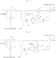
FIGS. 1 and 2 are process flow diagrams of a waste water incinerating method according to exemplary embodiments of the present application. -
FIG. 3 is a process flow diagram of a waste water incinerating method according to a comparative example. - Terms and words used in the present specification and claims are not to be construed as a general or dictionary meaning but are to be construed as meaning and concepts meeting the technical ideas of the present application based on a principle that the inventors may appropriately define the concepts of terms in order to describe their own inventions in the detailed description.
- In the present application, the term "stream" may refer to a flow of fluid in a process or may refer to a fluid itself flowing in a pipe. Specifically, the 'stream' may refer to both the fluid itself and a flow of the fluid flowing in a pipe connecting each device. In addition, the fluid may refer to a gas or a liquid.
- Hereinafter, the present application will be described in more detail to aid in understanding the present application.
- According to the present application, a waste water incinerating method is provided. The waste water incinerating method includes: (S10) supplying waste water to an evaporator and evaporating the waste water; (S20) supplying an evaporator top discharge stream discharged from the evaporator to an
incinerator 300 and incinerating the discharge stream; (S30) mixing two or more incinerator discharge streams including a first incinerator discharge stream and a second incinerator discharge stream discharged from the incinerator and forming a mixed discharge stream; and (S40) heat-exchanging the mixed discharge stream and a fresh air stream in afirst heat exchanger 400, wherein the first incinerator discharge stream is passed through asecond heat exchanger 410, then mixed with the second incinerator discharge stream to form the mixed discharge stream. - According to an embodiment of the present application, in modern society with consumer life and industrial activities, various wastes continue to be discharged as byproducts of material civilization activities, and among the wastes, waste water is a waste discharged in a liquid form according to an embodiment of the present application. Specifically, waste water is classified as household waste water and factory waste water according to sources thereof. Household waste water may refer to waste water discharged from each household and public buildings and business buildings that discharge waste substances similarly to households, and factory waste water may refer to waste water discharged from each factory, which may be referred to as industrial waste water in a broad sense and may collectively refer to waste water discharged from all industrial facilities.
- According to an embodiment of the present application, the waste water may be a liquid factory waste water containing various chemicals used in industrial production processes. For example, the waste water may be composed of organic substances including water, methanol, butanol, neopentyl glycol, sodium chloride, butyl aldehyde, octanol, trimethylamine, and the like.
- According to an embodiment of the present application, in the step (S10) of supplying waste water to an evaporator and evaporating the waste water, for example, while waste water is being supplied to the evaporator and heated to be evaporated, the waste water may be separated into a top discharge stream including water vapor, organic matter, and a plastic substance, and a bottom discharge stream including sludge. Here, the bottom discharge stream may be transported directly to a waste water treatment plant.
- According to an embodiment of the present application, the step (S10) of supplying the waste water to the evaporator and evaporating the waste water may be performed multiple times to more effectively separate the top discharge stream and the bottom discharge stream. For example, while the waste water is being supplied to a
first evaporator 100 and heated so as to be evaporated, the waste water may be separated into afirst evaporator 100 top discharge stream and thefirst evaporator 100 bottom discharge stream. Thereafter, thefirst evaporator 100 bottom discharge stream is secondly evaporated using asecond evaporator 110 so as to be separated into thesecond evaporator 110 top discharge stream and asecond evaporator 110 bottom discharge stream. Here, thesecond evaporator 110 top discharge stream may be mixed with thefirst evaporator 100 top discharge stream in afirst mixer 200 and discharged, and thesecond evaporator 110 bottom discharge stream may be transferred to the waste water treatment plant. - According to an embodiment of the present application, step (S20) of supplying the evaporator top discharge stream discharged from the evaporator to an
incinerator 300 and incinerating the same may be performed through a regenerative thermal oxidizer (RTO), and the evaporator top discharge stream may be supplied to theincinerator 300 and undergo a preheating step and an incineration step. Here, the evaporator top discharge stream may be a stream discharged after thefirst evaporator 100 top discharge stream and thesecond evaporator 110 top discharge stream are mixed in thefirst mixer 200. - According to an embodiment of the present application, temperature of the evaporator top discharge stream may be increased to 100°C or higher during the evaporation process. In this case, the evaporator top discharge stream itself having the temperature of 100°C or higher may be supplied to the
incinerator 300 and utilized as fuel. - The evaporator top discharge stream may first come into direct contact with a ceramic medium heat-stored in a heat storage layer so as to be preheated and enter the incinerator (i.e., RTO) 300. Here, a preheating temperature may differ depending on a heat storage efficiency design of the
incinerator 300, but the evaporator top discharge stream may be combined with heat of combustion generated while being burned by itself so as to be preheated up to a temperature of 800°C or higher, which is almost a temperature of theincinerator 300. After the preheated stream is completely incinerated in theincinerator 300, it provides heat to the ceramic medium to heat the ceramic medium, while passing through another heat storage layer, and theincinerator 300 discharge stream may be partially cooled. - According to an embodiment of the present application, the
incinerator 300 may discharge two or more incinerator discharge streams including a first incinerator discharge stream and a second incinerator discharge stream. For example, theincinerator 300 may further discharge third to fifth incinerator discharge streams. Here, the two or more incinerator discharge streams discharged from theincinerator 300 may form a mixed discharge stream through thethird mixer 220. - The two or more incinerator discharge streams including the first incinerator discharge stream and the second incinerator discharge stream may be mixed through the
third mixer 220 to form a mixed discharge stream in step S30, and the mixed discharge stream may be heat-exchanged with a fresh air stream in thefirst heat exchanger 400 in step S40 and then discharged to the atmosphere. - The mixed discharge stream and the fresh air stream may be heat-exchanged with each other by a counter-current flow, a co-current flow, or a cross flow in the
first heat exchanger 400. Here, the mixed discharge stream is discharged to the atmosphere, while being deprived of heat to the fresh air stream, whereby a temperature of the stream discharged to the atmosphere may be lowered. In addition, the fresh air stream which obtains heat from the mixed discharge stream and increases temperature may be supplied to theincinerator 300 to replace part of energy required in the incinerator. - Temperatures of the two or more incinerator discharge streams including the first incinerator discharge stream and the second incinerator discharge stream discharged from the
incinerator 300 may be different from each other. Specifically, the incinerator discharge streams separately discharged as two or more streams from the incinerator may have different discharge temperatures. As one example, when the incinerator discharge stream is discharged as the first incinerator discharge stream and the second incinerator discharge stream, the temperature of the first incinerator discharge stream may be higher than the temperature of the second incinerator discharge stream. - As such, since the incinerator discharge streams are discharged at different temperatures, the incinerator discharge streams may be utilized according to temperatures thereof. For example, the first incinerator discharge stream discharged at a high temperature may save process energy by additionally recycling waste heat in the
second heat exchanger 410 and asteam generator 500 to be described later. In addition, the second incinerator discharge stream discharged at a relatively low temperature may be returned to theincinerator 300 and recycled to preheat and heat theincinerator 300. - Specifically, the first incinerator discharge stream may be heat-exchanged with the fresh air stream which has passed through the
first heat exchanger 400 or the mixed stream of the fresh air stream and the evaporator top discharge stream in thesecond heat exchanger 410 and then mixed with the second incinerator discharge stream to form the mixed discharge stream. - Here, the first incinerator discharge stream may transfer heat to the fresh air stream or to the evaporator top discharge stream and thereby partly reduce its temperature while passing through the
second heat exchanger 410, , and thereby further reducing the temperature of the stream discharged to the atmosphere by reusing waste heat in the process . - Further, according to an embodiment of the present application, the temperature of the first incinerator discharge stream may be 400°C to 500°C, 420°C to 480°C, or 440°C to 460°C, and the temperature of the second incinerator discharge stream may be 100°C to 250°C, 130°C to 220°C, or 170°C to 190°C. As such, since energy is recycled by dividing the stream discharged from the
incinerator 300 into the first incinerator discharge stream having a relatively high temperature and the second incinerator discharge stream having a low temperature, energy may be saved more effectively. - In addition, according to an embodiment of the present application, the first incinerator discharge stream discharged from the
incinerator 300 may be a stream which has passed through asteam generator 500. Specifically, the first incinerator discharge stream discharged from theincinerator 300 may be discharged at a high temperature of 800°C to 1,000°C when discharged from theincinerator 300, and here, the first incinerator discharge stream having the high temperature may be lowered in temperature to 400°C to 500°C, while passing through thesteam generator 500, and in this process, thermal energy may be recycled during the formation of steam. While the first incinerator discharge stream passes through thesteam generator 500, steam formed from waste heat of the first incinerator discharge stream may be stored and used as a heat source in various processes. - In addition, according to an embodiment of the present application, the first incinerator discharge stream may be heat-exchanged with the fresh air stream which has passed through the
first heat exchanger 400 or the mixed stream of the fresh air stream and the evaporator top discharge stream in thesecond heat exchanger 410. The first incinerator discharge stream and the fresh air stream which has passed through thefirst heat exchanger 400 or the mixed stream of the fresh air stream and the evaporator top discharge stream may be heat-exchanged with each other by a counter-current flow, a co-current flow, or a cross flow in thesecond heat exchanger 410. Here, the mixed stream of the fresh air stream and the evaporator top discharge stream may refer to a mixed stream discharged after the fresh air stream and the evaporator top discharge stream which has passed through thefirst heat exchanger 400 are mixed in thesecond mixer 210. Here, in some cases, off gas generated in the waste water treatment plant may be further mixed in addition to the fresh air stream and the evaporator top discharge stream which has passed through thefirst heat exchanger 400, in thesecond mixer 210. - The first incinerator discharge stream may be heat-exchanged with the fresh air stream which has passed through the
first heat exchanger 400 or the mixed stream of the fresh air stream and the evaporator top discharge stream in thesecond heat exchanger 410, thereby providing heat to the fresh air stream or the mixed stream so as to be recycled as a heat source of waste water incineration, and at the same time, the first incinerator discharge stream heat-exchanged in thesecond heat exchanger 410 may be mixed with the second incinerator discharge stream at a lower temperature to form a mixed discharge stream, and the mixed discharge stream may transfer heat to the fresh air stream in thefirst heat exchanger 400 so as to be discharged to the atmosphere at an even lower temperature. - Further, according to an embodiment of the present application, the temperature of the first incinerator discharge stream which has passed through the
second heat exchanger 410 may be lower than the temperature of the first incinerator discharge stream before passing through thesecond heat exchanger 410. Specifically, as described above, the first incinerator discharge stream is heat-exchanged with the fresh air stream which has passed through thefirst heat exchanger 400 or the mixed stream of the fresh air stream and the evaporator top discharge stream in thesecond heat exchanger 410. Here, the first incinerator discharge stream provides heat to the fresh air stream or the mixed stream of the fresh air stream and the evaporator top discharge stream, and thus, the temperature of the first incinerator discharge stream after passing through thesecond heat exchanger 410 is lowered. For example, the temperature of the first incinerator discharge stream which has passed through thesecond heat exchanger 410 may be 250°C to 350°C, 270°C to 330°C or 280°C to 300°C. It can be seen that the temperature of the first incinerator discharge stream has been reduced as compared to 400°C to 500°C, which is the temperature of the first incinerator discharge stream before passing through thesecond heat exchanger 410. - In addition, according to an embodiment of the present application, the temperature of the stream discharged to the atmosphere from the
first heat exchanger 400 may be 90°C or lower. For example, the temperature of the stream discharged to the atmosphere may be 30°C to 90°C, 50°C to 90°C, or 70°C to 90°C. This is a significantly lower temperature compared to the temperature of the stream discharged to the atmosphere during the incineration of waste water using the existing RTO, and through this, the waste water incinerating method according to the present application recycles a large amount of heat in the waste water incinerating process and saves a large amount of energy accordingly. - Specifically, the waste water incinerating method according to the present application primarily recycles heat by exchanging heat of the first incinerator discharge stream having a high temperature with the fresh air stream which has passed through the
first heat exchanger 400 or the mixed stream of the fresh air stream and the evaporator top discharge stream in thesecond heat exchanger 410, and secondarily recycles heat by exchanging heat of the mixed discharge stream discharged from theincinerator 300 with the fresh air stream in thefirst heat exchanger 400, thereby effectively saving energy. - Further, according to an embodiment of the present application, the fresh air stream which has passed through the
first heat exchanger 400 or the mixed stream of the fresh air stream and the evaporator top discharge stream may be supplied to theincinerator 300 through thesecond heat exchanger 410. A temperature of the fresh air stream or the mixed stream of the fresh air stream and the evaporator top discharge stream which has passed through thesecond heat exchanger 410 may be higher than a temperature thereof before passing through thesecond heat exchanger 410. Specifically, the temperature of the fresh air stream or the mixed stream of the fresh air stream and the evaporator top discharge stream may be 200°C to 300°C, 215°C to 260°C, or 230°C to 250°C. - Specifically, the fresh air stream may obtain heat from the stream discharged from the
incinerator 300 by heat exchange through thefirst heat exchanger 400 and thesecond heat exchanger 410 so as to be supplied in a high temperature state to theincinerator 300. In this case, energy required for heating in theincinerator 300 may be saved as compared to a case where air is supplied at room temperature to theincinerator 300. For example, the temperature of the fresh air stream which has passed through thefirst heat exchanger 400 may be 150°C to 230°C, 170°C to 220°C, or 200°C to 210°C. In addition, the temperature of the fresh air stream which has passed through the second heat exchanger may be 250°C to 350°C, 270°C to 320°C, or 280°C to 300°C. This hot fresh air stream may be mixed with the evaporator top discharge stream in thesecond mixer 210, and the mixed stream may be supplied to theincinerator 300. Here, theincinerator 300 may be a regenerative thermal oxidizer (RTO). In this case, the evaporator top discharge stream may be partially heated due to the fresh air stream before being supplied to theincinerator 300, thereby saving fuel input to obtain the energy used for preheating the waste water in theincinerator 300. - In addition, the mixed stream of the fresh air stream and the evaporator top discharge stream may obtain heat from the first incinerator discharge stream discharged from the
incinerator 300 by heat exchange through thesecond heat exchanger 410 so as to be supplied in a high temperature state to theincinerator 300. This saves the energy required for heating the waste water in theincinerator 300 as compared to the case where the mixed stream of the fresh air stream and the evaporator top discharge stream discharged from thesecond mixer 210 is immediately supplied to theincinerator 300. For example, the temperature of the mixed stream of the fresh air stream and the evaporator top discharge stream which has passed through thesecond heat exchanger 410 may be 220°C to 270°C, 230°C to 260°C, or 240°C to 250°C. This is a high temperature as compared to 160°C to 180°C which is a general temperature of the evaporator top discharge stream, thus saving the amount of energy required for incinerating the waste water in theincinerator 300. - In addition, according to an embodiment of the present application, in the step (S20) of supplying the evaporator top discharge stream discharged from the evaporator to the
incinerator 300 and incinerating the stream, if necessary, fuel may be input to obtain the energy required for preheating and heating waste water. In the step of supplying the evaporator top discharge stream discharged from the evaporator to theincinerator 300 and incinerating the stream, fuel may be input at 800 kg/hr. or lower, for example, may be input at 0 kg/hr. to 800 kg/hr., 400 kg/hr. to 800 kg/hr., or 700 kg/hr. to 800 kg/hr. - In addition, according to an embodiment of the present application, a portion of the second incinerator discharge stream discharged from the
incinerator 300 may be returned to theincinerator 300 and recycled to preheat and heat theincinerator 300. - In addition, according to an embodiment of the present application, air may be further supplied to further facilitate the incineration of waste water in the
incinerator 300. - In addition, according to an embodiment of the present application, a bottom discharge stream of the evaporator may be moved to a waste water treatment plant and an off gas that occurs in the waste water treatment plant may be supplied to the
incinerator 300. Through this, the waste water incinerating method according to the present application may simultaneously incinerate both the waste water and the off gas generated in the waste water treatment plant. - According to the present application, a waste water incinerating apparatus is provided. The waste water incinerating apparatus includes an evaporator evaporating supplied waste water and supplying an evaporated top discharge stream to an incinerator, an
incinerator 300 receiving the top discharge stream supplied from the evaporator and incinerating the evaporator top discharge stream to supply two or more incinerator discharge streams including a first incinerator discharge stream and a second incinerator discharge stream to athird mixer 220, thethird mixer 220 receiving the two or more incinerator discharge streams including the first incinerator discharge stream and the second incinerator discharge stream supplied from theincinerator 300 and supplying a mixed discharge stream of the first incinerator discharge stream and the second incinerator discharge stream to afirst heat exchanger 400, thefirst heat exchanger 400 heat-exchanging the mixed discharge stream supplied from thethird mixer 220 with the supplied fresh air stream, and asecond heat exchanger 410 heat-exchanging a first incinerator discharge stream discharged from theincinerator 300 and supplying the heat-exchanged first incinerator discharge stream to thethird mixer 220. - According to an embodiment of the present application, the waste water incinerating apparatus according to the present application may be an apparatus for performing a process according to the waste water incinerating method described above.
- According to an embodiment of the present application, the waste water incinerating apparatus according to the present application may be described with reference to
FIGS. 1 and 2 hereinafter. For example, the waste water incinerating apparatus may include thefirst evaporator 100 primarily evaporating supplied waste water to separate the waste water into a first top discharge stream including water vapor, organic matter, plastic substance, and the like and a first bottom discharge stream including sludge. In addition, the first bottom discharge stream discharged from thefirst evaporator 100 may be secondly evaporated using thesecond evaporator 110 so as to be separated into a second top discharge stream and a second bottom discharge stream. Here, the second bottom discharge stream is transferred to the waste water treatment plant, and the second top discharge stream may be mixed with the first top discharge stream in thefirst mixer 200 and discharged. The stream discharged from thefirst mixer 200 may be supplied to thesecond mixer 210 and mixed with the off gas generated in the waste water treatment plant and a fresh air stream in thesecond mixer 210. Here, the fresh air stream may have been heat-exchanged, while passing through thefirst heat exchanger 400 or thesecond heat exchanger 410. - The mixed stream discharged from the
second mixer 210 may be transferred to theincinerator 300. Additional fuel or air may be selectively introduced to theincinerator 300. Theincinerator 300 may incinerate the mixed stream discharged from thesecond mixer 210 and separately discharge the first incinerator discharge stream and the second incinerator discharge stream according to temperatures. - The first incinerator discharge stream and the second incinerator discharge stream may be mixed in the
third mixer 220. Here, the first incinerator discharge stream may be heat-exchanged in thesecond heat exchanger 410 and then mixed with the second incinerator discharge stream in thethird mixer 220. - Before being supplied to the
second heat exchanger 410, the first incinerator discharge stream may form steam, while passing through thesteam generator 500, and then be supplied to thesecond heat exchanger 410. - The mixed stream mixed in the
third mixer 220 may be supplied to thefirst heat exchanger 400, heat-exchanged with a fresh air stream in thefirst heat exchanger 400, and then discharged to the atmosphere. - The first incinerator discharge stream exchanges heat with the fresh air stream which has passed through the
first heat exchanger 400 or the mixed stream of the fresh air stream and the evaporator top discharge stream in thesecond heat exchanger 410, and the fresh air stream or the mixed stream of the fresh air stream and the evaporator top discharge stream which has passed through thesecond heat exchanger 410 may be supplied to theincinerator 300. - First, when the first incinerator discharge stream is heat-exchanged with the fresh air stream discharged from the
first heat exchanger 400 in thesecond heat exchanger 410, the heat-exchanged first incinerator discharge stream may be mixed with the second incinerator discharge stream in thethird mixer 220, and the heat-exchanged fresh air stream may be supplied to thesecond mixer 210 and mixed with the mixed stream supplied from thefirst mixer 200 and a gas discharged from the waste heat treatment plant and then supplied to theincinerator 300. - In addition, when the first incinerator discharge stream is heat-exchanged with the mixed stream of the fresh air stream and the evaporator top discharge stream in the
second heat exchanger 410, the heat-exchanged first incinerator discharge stream may be mixed with the second incinerator discharge stream in thethird mixer 220 and the mixed stream of the heat-exchanged fresh air stream and the evaporator top discharge stream may be supplied to theincinerator 300. - As described above, the waste water incinerating method and apparatus according to the present application have been described and illustrated in the drawings, but only the essential components for understanding the present application have been described and illustrated, and a process and a device not separately described and illustrated in addition to the above described process and device, may be appropriately applied and used to implement the waste water incinerating method and apparatus according to the present application.
- Hereinafter, the present application will be described in more detail with reference to examples. However, the following examples are intended to illustrate the present application and it is apparent to those skilled in the art that various changes and modifications may be made within the scope and spirit of the present application, and the scope of the present application is not limited thereto.
- Regarding the process flow diagram shown in
FIG. 1 , a process was simulated using the Aspen Plus Simulator of Aspen Technology, Inc. - Here, a temperature of waste water supplied to the first evaporator was set to 30°C, a pressure thereof was set to 0.2 kg/sqcmg, and a mass flow rate was set to 10,000 kg/hr. Components of the waste water included 87.57 wt% of water, 4.90% wt% of methanol, 2.33% wt% of butanol, 1.65 wt% of neopentyl glycol (NPG), 2.91 wt% of sodium chloride, and 0.64% wt% of organic substances including butyl aldehyde, octanol, trimethylamine, and the like.
- In addition, the fresh air stream supplied to the incinerator was set to 20°C and the composition was set to 21 mol% of oxygen and 79 mol% of nitrogen.
- A process was performed in the same manner as in Example 1, except for simulating a process using the Aspen Plus Simulator of Aspen Technology, Inc. in accordance with the process flow diagram shown in
FIG. 2 . - A process was performed in the same manner as in Example 1, except that the process was simulated using the Aspen Plus Simulator of Aspen Technology, Inc. in accordance with the process flow diagram shown in
FIG. 3. FIG. 3 is a process flow diagram without the second heat exchanger in the waste water incinerating process according to the present application. - As a result of the process simulation according to Examples and Comparative Example, temperatures of the respective streams according to the process flows are shown in Table 1 below, and the amount of fuel input to the incinerator and thermal properties of the heat exchangers are shown in Table 2 below.
[Table 1] Stream Temperature (°C) Example 1 Example 2 Comparative Example Waste water 30.0 30.0 30.0 Top discharge stream of first evaporator 102.0 102.0 102.0 Bottom discharge stream of first evaporator 102.0 102.0 102.0 Top discharge stream of second evaporator 105.0 105.0 105.0 Bottom discharge stream of second evaporator 105.0 105.0 105.0 Discharge stream of first mixer 120.0 120.0 120.0 Off gas supply stream from waste water treatment plant 90.0 90.0 90.0 Stream supplied from second heat exchanger to second mixer 286.5 - - Stream supplied from second mixer to second heat exchanger - 171.7 - Stream supplied to incinerator 239.5 243.9 171.7 Stream supplied from incinerator to steam generator 903.0 903.0 903.0 Stream supplied from steam generator to second heat exchanger 450.0 450 - Stream supplied from second heat exchanger to third mixer 291.5 248.9 - Stream supplied from steam generator to third mixer - - 450.0 Stream supplied from third mixer to first heat exchanger 217.7 203.2 273.4 Fresh air stream supplied to first heat exchanger 20.0 20.0 20.0 Stream supplied from first heat exchanger to second heat exchanger 207.7 - - Stream discharged from first heat exchanger to second mixer - 193.2 193.2 Stream discharged from first heat exchanger to atmosphere 87.1 82.5 155.0 [Table 2] Example 1 Example 2 Comparative example First heat exchanger Second heat exchanger First+second heat exchangers First heat exchanger Second heat exchanger First+second heat exchangers Calculated heat duty (Gcal/hr) 2.42 1.03 3.43 2.22 1.30 3.52 2.22 Required exchanger area (sqm) 114.88 11.72 126.60 105.91 13.53 119.44 27.06 Actual exchanger area (sqm) 144.88 11.72 126.60 105.91 13.53 119.44 27.06 Average U (kcal/hr-sqm-K) 730.87 730.87 730.87 730.87 730.87 730.87 730.87 UA (cal/sec-K) 23323.14 2378.65 - 21501.8 2746 - 5494.20 LMTD (corrected) 28.75 118.78 - 28.66 131.60 - 108.80 Amount of fuel input to incinerator (kg/hr) 782.4 775.2 891.4 * Calculated heat duty, required exchanger area, actual exchanger area, average U, UA, and LMTD (corrected) are values calculated through calculation formulas using factors such as a composition of each stream in a process, a flow rate, a temperature, and a heat capacity, etc. - Calculated heat duty: Q=specific heat at constant pressure × flow rate × (temperature difference between inlet and outlet) - Required exchanger area, actual exchanger area: A=Q/K×ΔT (K is overall coefficient of heat transfer, ΔT is logarithmic mean temperature difference (LMTD) between inlet and outlet temperatures) - Average U: U=1/(1/h+x/k)=Q/(A×ΔT) (h is film coefficient of heat transfer, k is heat transfer coefficient of heated metal surface, x is thickness of heated metal surface, A is area of heat exchanger, ΔT is logarithmic mean temperature difference between stream and heated surface) - UA (actual heat transfer coefficient): Average U × actual exchanger area - LMTD (corrected): LMTD × correction factor - First, referring to Table 1, comparing the waste water incinerating process flows according to Examples 1 and 2 with the waste water incinerating process flow according to Comparative Example, it can be seen that a temperature of a stream discharged from the
third mixer 220 and supplied to thefirst heat exchanger 400, a temperature of a stream discharged from thesecond mixer 210 and supplied to theincinerator 300, and a temperature of a stream discharged from thefirst heat exchanger 400 to the atmosphere are significantly different according to installation of thesecond heat exchanger 410. - Specifically, in the waste water incinerating process of Example 1, by installing the
second heat exchanger 410, the stream at 450°C discharged from thesteam generator 500 is heat-exchanged in thesecond heat exchanger 410 so as to reduce its temperature to 291.5°C and then supplied to thethird mixer 220. - In addition, in the waste water incinerating process of Example 2, by installing the
second heat exchanger 410, the stream at 450°C discharged from thesteam generator 500 is heat-exchanged in thesecond heat exchanger 410 so as to reduce its temperature to 248.9°C and then supplied to thethird mixer 220. - Meanwhile, in the waste water incinerating process of Comparative Example in which the second heat exchanger is not installed, a stream at 450°C discharged from the
steam generator 500 is directly supplied to thethird mixer 220. Thus, in Examples 1 and 2 and Comparative Example, the temperatures of the stream discharged from thethird mixer 220 and supplied to thefirst heat exchanger 400 are 217.7°C, 203.2°C and 273.4°C respectively, and thus it can be seen that the temperature of the stream discharged from thethird mixer 220 and supplied to thefirst heat exchanger 400 is significantly low. - In addition, in the first embodiment, a stream supplied from the
third mixer 220 and a fresh air stream are heat-exchanged in thefirst heat exchanger 400, and the fresh air stream heat-exchanged in thefirst heat exchanger 400 is supplied again to theincinerator 300 through thesecond mixer 210. Here, the fresh air stream at 20°C is heat-exchanged with the stream at 217.7°C supplied from thethird mixer 220 and discharged at a temperature of 207.7°C from thefirst heat exchanger 400. Thereafter, the fresh air stream discharged from thefirst heat exchanger 400 is supplied to thesecond heat exchanger 410 and heat-exchanged with a first incinerator discharge stream at 450°C. Accordingly, in Example 1, the fresh air stream is increased in temperature to 286.5°C, while recycling heat in the process through thefirst heat exchanger 400 and thesecond heat exchanger 410. The fresh air stream increased in temperature is mixed with a stream discharged from thefirst mixer 200 and a gas discharged from the waste water treatment plant in thesecond mixer 210, and the mixed stream is supplied at a temperature of 239.5°C to theincinerator 300. - In addition, in Example 2, the stream discharged from the
steam generator 500 is supplied to thesecond heat exchanger 410, and the stream discharged from thesteam generator 500 and the stream discharged from thesecond mixer 210 are heat-exchanged in thesecond heat exchanger 410. Here, the stream discharged from thesecond mixer 210 obtains heat from the stream discharged from thesteam generator 500 and is supplied at a temperature of 243.9°C to theincinerator 300. - Meanwhile, in Comparative Example, a fresh air stream at 20°C is heat-exchanged with the stream at 273.4°C supplied from the
third mixer 220 and discharged at a temperature of 193.2°C from thefirst heat exchanger 400. Thereafter, the fresh air stream discharged from thefirst heat exchanger 400 is directly mixed with the stream discharged from thefirst mixer 200 and the gas discharged from the waste water treatment plant in thesecond mixer 210 and supplied at a temperature of 171.7°C to theincinerator 300. As a result, in Comparative Example, the stream supplied to theincinerator 300 is supplied at a temperature of 171.7°C, but the stream is supplied at a temperature of 239.5°C in Example 1 and is supplied at a temperature of 243.9°C in Example 2, and thus, Examples 1 and 2 can save heat required to incinerate the waste water in theincinerator 300 by the temperature difference compared to Comparative Example. - In addition, due to the temperature difference of the stream discharged from the
third mixer 220 and supplied to thefirst heat exchanger 400, there is also a difference in the temperature discharged to the atmosphere. Specifically, in the case of Example 1, the stream at 217.7°C is discharged from thethird mixer 220 and supplied to thefirst heat exchanger 400, and the stream is heat-exchanged with the fresh air stream at 20°C in thefirst heat exchanger 400. Here, the stream discharged from thethird mixer 220 and supplied to thefirst heat exchanger 400 is discharged to the atmosphere at 87.1°C. - In addition, in Example 2, the stream at 203.2°C is discharged from the
third mixer 220 and supplied to thefirst heat exchanger 400, and the stream is heat-exchanged with the fresh air stream at 20°C in thefirst heat exchanger 410. Here, the stream discharged from thethird mixer 220 and supplied to thefirst heat exchanger 400 is discharged to the atmosphere at 82.5°C. - Meanwhile, in Comparative Example, a stream at 273.4°C having a high temperature as compared to Examples 1 and 2 is discharged from the
third mixer 220 and supplied to thefirst heat exchanger 400, and the stream is heat-exchanged with a fresh air stream at 20°C in thefirst heat exchanger 400. Here, the stream discharged from thethird mixer 220 and supplied to thefirst heat exchanger 400 is discharged to the atmosphere at 155°C, which is significantly higher than 87.1°C and 82.5°C which are atmosphere discharge temperatures according to Examples 1 and 2. - As a result, this means that, heat corresponding to 67.9°C to 72.5°C was recycled in the process by installing the
second heat exchanger 410 in Examples 1 and 2. - In addition, an energy saving effect according to the installation of the
second heat exchanger 410 may also be confirmed in Table 2 above. Referring to Table 2, it can be seen that, the amount of heat obtained from the heat exchanger in Examples 1 and 2 were 3.43 Gcal/hr and 3.52 Gcal/hr respectively, and about 1.21 Gcal/hr to 1.3 Gcal/hr was saved as compared to Comparative Example. - In addition, it can be seen that actual heat transfer coefficients (UAs) of the
first heat exchanger 400 in Examples 1 and 2 were 23323.14 cal/sec-K and 21501.8 cal/sec-K respectively, and heat transfer rates thereof are excellent as compared to Comparative Example in which the UA is 5494.20 cal/sec-K. - In addition, in the case of Examples 1 and 2, the amounts of fuel input to the incinerator were 782.4 kg/hr and 775.2 kg/hr respectively, and thus it can be seen that fuel of about 114.6 kg to 116.2 kg was saved per hour as compared to Comparative Example.
Claims (10)
- A waste water incinerating method comprising:(S10) supplying waste water to an evaporator and evaporating the waste water;(S20) supplying an evaporator top discharge stream discharged from the evaporator to an incinerator and incinerating the evaporator top discharge stream;(S30) mixing two or more incinerator discharge streams including a first incinerator discharge stream and a second incinerator discharge stream discharged from the incinerator and forming a mixed discharge stream; and(S40) heat-exchanging the mixed discharge stream and a fresh air stream in a first heat exchanger,wherein he first incinerator discharge stream is passed through a second heat exchanger, then mixed with the second incinerator discharge stream to form the mixed discharge stream.
- The waste water incinerating method of claim 1, wherein a temperature of the first incinerator discharge stream is higher than a temperature of the second incinerator discharge stream.
- The waste water incinerating method of claim 1, wherein the first incinerator discharge stream is heat-exchanged in the second heat exchanger with a fresh air stream which has passed through the first heat exchanger or a mixed stream of the fresh air stream and the evaporator top discharge stream.
- The waste water incinerating method of claim 1, wherein a temperature of the first incinerator discharge stream which has passed through the second heat exchanger is lower than a temperature of the first incinerator discharge stream before passing through the second heat exchanger.
- The waste water incinerating method of claim 1, wherein a temperature of a stream discharged to the atmosphere from the first heat exchanger is 90°C or lower.
- The waste water incinerating method of claim 3, wherein the fresh air stream or the mixed stream of the fresh air stream and the evaporator top discharge stream heat-exchanged in the second heat exchanger is supplied to the incinerator, and a temperature of the fresh air stream or the mixed stream of the fresh air stream and the evaporator top discharge stream which has passed through the second heat exchanger is higher than a temperature thereof before passing through the second heat exchanger.
- The waste water incinerating method of claim 6, wherein the temperature of the fresh air stream or the mixed stream of the fresh air stream and the evaporator top discharge stream which has passed through the second heat exchanger is 200°C to 300°C.
- A waste water incinerating apparatus comprising:an evaporator evaporating supplied waste water and supplying an evaporator top discharge stream to an incinerator;the incinerator receiving the evaporator top discharge stream supplied from the evaporator and incinerating the evaporator top discharge stream to supply two or more incinerator discharge streams including a first incinerator discharge stream and a second incinerator discharge stream to a third mixer;the third mixer receiving the two or more incinerator discharge streams including the first incinerator discharge stream and the second incinerator discharge stream supplied from the incinerator and supplying a mixed discharge stream of the first incinerator discharge stream and the second incinerator discharge stream to a first heat exchanger;the first heat exchanger heat-exchanging the mixed discharge stream supplied from the third mixer with a supplied fresh air stream; anda second heat exchanger heat-exchanging the first incinerator discharge stream discharged from the incinerator and supplying the heat-exchanged first incinerator discharge stream to the third mixer.
- The waste water incinerating apparatus of claim 8, wherein the first incinerator discharge stream is heat-exchanged with a fresh air stream discharged from the first heat exchanger or a mixed stream of the fresh air stream and the evaporator top discharge stream in the second heat exchanger, and the fresh air stream or the mixed stream of the fresh air stream and the evaporator top discharge stream which has passed through the second heat exchanger is supplied to the incinerator.
- The waste water incinerating apparatus of claim 8, wherein the incinerator is a regenerative thermal oxidizer (RTO).
Applications Claiming Priority (3)
| Application Number | Priority Date | Filing Date | Title |
|---|---|---|---|
| KR20190062726 | 2019-05-28 | ||
| KR1020200005770A KR102476990B1 (en) | 2019-05-28 | 2020-01-16 | Incineration method and equipment of wastewater |
| PCT/KR2020/000920 WO2020242006A1 (en) | 2019-05-28 | 2020-01-20 | Wastewater incineration method and wastewater incineration apparatus |
Publications (3)
| Publication Number | Publication Date |
|---|---|
| EP3778495A1 true EP3778495A1 (en) | 2021-02-17 |
| EP3778495A4 EP3778495A4 (en) | 2021-06-23 |
| EP3778495B1 EP3778495B1 (en) | 2025-12-10 |
Family
ID=73779313
Family Applications (1)
| Application Number | Title | Priority Date | Filing Date |
|---|---|---|---|
| EP20799595.2A Active EP3778495B1 (en) | 2019-05-28 | 2020-01-20 | Wastewater incineration method and wastewater incineration apparatus |
Country Status (5)
| Country | Link |
|---|---|
| US (1) | US11851348B2 (en) |
| EP (1) | EP3778495B1 (en) |
| JP (1) | JP7106677B2 (en) |
| KR (1) | KR102476990B1 (en) |
| CN (1) | CN112313177A (en) |
Family Cites Families (23)
| Publication number | Priority date | Publication date | Assignee | Title |
|---|---|---|---|---|
| DE2150414C3 (en) * | 1971-10-09 | 1978-10-19 | Josef Martin Feuerungsbau Gmbh, 8000 Muenchen | Method and device for the simultaneous incineration of waste and sewage sludge |
| US4232614A (en) * | 1979-06-06 | 1980-11-11 | Dorr-Oliver Incorporated | Process of incineration with predrying of moist feed using hot inert particulates |
| US4714032A (en) * | 1985-12-26 | 1987-12-22 | Dipac Associates | Pollution-free pressurized combustion utilizing a controlled concentration of water vapor |
| US5000099A (en) * | 1985-12-26 | 1991-03-19 | Dipac Associates | Combination of fuels conversion and pressurized wet combustion |
| US6125633A (en) * | 1998-06-08 | 2000-10-03 | Strohmeyer, Jr.; Charles | Sewage organic waste compaction and incineration system integrated with a gas turbine power driver exhaust gas flow stream |
| KR19980082082A (en) * | 1998-08-21 | 1998-11-25 | 오석인 | Evaporative Regenerative Incineration System of Organic Wastewater |
| KR20030062495A (en) | 2002-01-17 | 2003-07-28 | 김춘웅 | Rotary killen tape waste water disposal plant |
| KR100627133B1 (en) | 2004-06-23 | 2006-09-25 | 배성근 | System for mixed incineration of organic sludge and flammable waste |
| KR101125864B1 (en) | 2009-05-28 | 2012-03-29 | 주식회사 에이치엔 | A Processing Apparatus for Wastewater Treatment |
| KR101190250B1 (en) * | 2009-06-03 | 2012-10-12 | 한영무 | System For Treating Waste Water Containing Material Having Low Boiling Point |
| KR100967747B1 (en) | 2010-03-24 | 2010-07-05 | 노영수 | Process and system for processing liquid waste |
| KR101154826B1 (en) | 2011-06-23 | 2012-06-18 | 코오롱환경서비스주식회사 | Sewage sludge processing equipment using direct buring deo-dorization device |
| TWM445580U (en) * | 2012-08-24 | 2013-01-21 | Gst Corp | Organic waste water purification and incineration processing device |
| CN104359113B (en) * | 2014-11-04 | 2016-08-24 | 宜兴市智博环境设备有限公司 | A kind of waste gas, liquid waste incineration system and method |
| KR101721137B1 (en) | 2015-03-30 | 2017-04-11 | 한국기계연구원 | Submerged burner type wastewater treatment System |
| JP6086944B2 (en) | 2015-06-12 | 2017-03-01 | 三菱重工環境・化学エンジニアリング株式会社 | Sludge incineration plant |
| KR101839781B1 (en) * | 2015-06-18 | 2018-03-20 | 주식회사 엘지화학 | Heat recovery apparatus |
| KR101568117B1 (en) * | 2015-07-03 | 2015-11-10 | 신대원보일러 주식회사 | Wastewater evaporator for liquid waste incineration apparatus |
| JP6241525B1 (en) * | 2016-09-16 | 2017-12-06 | 栗田工業株式会社 | Wastewater recovery method and apparatus for incineration plant adopting wastewater closed system |
| CN106348371B (en) * | 2016-11-17 | 2019-04-12 | 山东大学 | The minimizing technology of volatile organic matter in a kind of water difficult to degrade |
| KR101773080B1 (en) * | 2017-04-10 | 2017-09-12 | 신대원보일러 주식회사 | Wastewater evaporator for waste burnig furnace |
| KR102002409B1 (en) | 2017-06-05 | 2019-07-25 | 이경우 | Waste incinerator |
| CN109442438B (en) * | 2018-10-24 | 2020-03-31 | 江苏大信环境科技有限公司 | Comprehensive treatment process and system for ammonia-containing organic waste gas and ammonia-containing organic wastewater |
-
2020
- 2020-01-16 KR KR1020200005770A patent/KR102476990B1/en active Active
- 2020-01-20 US US17/054,736 patent/US11851348B2/en active Active
- 2020-01-20 CN CN202080002729.6A patent/CN112313177A/en active Pending
- 2020-01-20 EP EP20799595.2A patent/EP3778495B1/en active Active
- 2020-01-20 JP JP2020563453A patent/JP7106677B2/en active Active
Also Published As
| Publication number | Publication date |
|---|---|
| KR102476990B1 (en) | 2022-12-13 |
| CN112313177A (en) | 2021-02-02 |
| US11851348B2 (en) | 2023-12-26 |
| JP2021529294A (en) | 2021-10-28 |
| EP3778495A4 (en) | 2021-06-23 |
| KR20200136805A (en) | 2020-12-08 |
| JP7106677B2 (en) | 2022-07-26 |
| US20230159351A1 (en) | 2023-05-25 |
| EP3778495B1 (en) | 2025-12-10 |
Similar Documents
| Publication | Publication Date | Title |
|---|---|---|
| Shah et al. | Opportunities for heat exchanger applications in environmental systems | |
| CN102190362B (en) | Supercritical water oxidation reaction system for obtaining heat supplemented by auxiliary fuel | |
| KR19980082082A (en) | Evaporative Regenerative Incineration System of Organic Wastewater | |
| Huang et al. | Effect of hydrothermal flame generation methods on energy consumption and economic performance of supercritical water oxidation systems | |
| CN103834441B (en) | A kind of gasification production waste recoverying and utilizing method | |
| EP3778495B1 (en) | Wastewater incineration method and wastewater incineration apparatus | |
| EP3770497B1 (en) | Wastewater incineration method and wastewater incineration apparatus | |
| CN103752354A (en) | Regeneration method and device used for deactivation catalyst layer of membrane ozone catalytic reactor | |
| CN106348371A (en) | method for removing volatile organic compounds from degradation-resistant water | |
| CN112044105A (en) | Device for evaporating by utilizing humidity difference of gas | |
| CN214456966U (en) | A high-concentration organic sewage vaporization and catalytic incineration equipment | |
| CN109748349B (en) | System and method for treating phenolic wastewater through pyrolysis | |
| CN212315616U (en) | High-salt-content high-concentration organic wastewater integrated treatment system | |
| RU2049740C1 (en) | Circulating water supply system of coke and byproduct process | |
| CN111453793A (en) | A thermal cracking treatment system and method for high-concentration COD organic waste liquid | |
| CN112777666B (en) | High-concentration organic sewage vaporization and catalytic incineration process and equipment | |
| CN216799355U (en) | Treatment system for VOCs gas produced by semi-coke | |
| CN101200646B (en) | Waste water zero discharging method for coke-oven gas dew-point returning process | |
| CN108675532B (en) | Treatment process for realizing zero discharge of high-salt high-organic matter wastewater by utilizing waste heat | |
| KR20030012676A (en) | Incinerator of Volatile Organic Compound Using Catalytic Combustion | |
| CN110500599B (en) | Energy saving and emission reduction system for gravure organic waste gas | |
| CN209259860U (en) | A kind of processing system for realizing high organic wastewater zero-emission with high salt using waste heat | |
| WO2020242006A1 (en) | Wastewater incineration method and wastewater incineration apparatus | |
| CN110566980A (en) | High-salt high-concentration chlorine-containing wastewater steam recycling high-temperature thermal oxidation equipment and process | |
| CN111285523A (en) | Method and device for treating ammonia-containing wastewater |
Legal Events
| Date | Code | Title | Description |
|---|---|---|---|
| STAA | Information on the status of an ep patent application or granted ep patent |
Free format text: STATUS: UNKNOWN |
|
| STAA | Information on the status of an ep patent application or granted ep patent |
Free format text: STATUS: THE INTERNATIONAL PUBLICATION HAS BEEN MADE |
|
| PUAI | Public reference made under article 153(3) epc to a published international application that has entered the european phase |
Free format text: ORIGINAL CODE: 0009012 |
|
| STAA | Information on the status of an ep patent application or granted ep patent |
Free format text: STATUS: REQUEST FOR EXAMINATION WAS MADE |
|
| 17P | Request for examination filed |
Effective date: 20201109 |
|
| AK | Designated contracting states |
Kind code of ref document: A1 Designated state(s): AL AT BE BG CH CY CZ DE DK EE ES FI FR GB GR HR HU IE IS IT LI LT LU LV MC MK MT NL NO PL PT RO RS SE SI SK SM TR |
|
| AX | Request for extension of the european patent |
Extension state: BA ME |
|
| A4 | Supplementary search report drawn up and despatched |
Effective date: 20210526 |
|
| RIC1 | Information provided on ipc code assigned before grant |
Ipc: C02F 1/16 20060101AFI20210520BHEP Ipc: C02F 1/04 20060101ALI20210520BHEP Ipc: B01D 53/00 20060101ALI20210520BHEP Ipc: C02F 101/32 20060101ALI20210520BHEP Ipc: B01D 3/00 20060101ALI20210520BHEP Ipc: F23G 5/00 20060101ALI20210520BHEP Ipc: F23G 5/46 20060101ALI20210520BHEP |
|
| STAA | Information on the status of an ep patent application or granted ep patent |
Free format text: STATUS: EXAMINATION IS IN PROGRESS |
|
| 17Q | First examination report despatched |
Effective date: 20211223 |
|
| DAV | Request for validation of the european patent (deleted) | ||
| DAX | Request for extension of the european patent (deleted) | ||
| REG | Reference to a national code |
Ref country code: DE Ref legal event code: R079 Free format text: PREVIOUS MAIN CLASS: C02F0001160000 Ipc: F23G0007060000 Ref document number: 602020063731 Country of ref document: DE |
|
| GRAP | Despatch of communication of intention to grant a patent |
Free format text: ORIGINAL CODE: EPIDOSNIGR1 |
|
| STAA | Information on the status of an ep patent application or granted ep patent |
Free format text: STATUS: GRANT OF PATENT IS INTENDED |
|
| RIC1 | Information provided on ipc code assigned before grant |
Ipc: F23G 7/06 20060101AFI20250826BHEP Ipc: C02F 1/04 20060101ALI20250826BHEP Ipc: C02F 1/16 20060101ALI20250826BHEP Ipc: C02F 101/32 20060101ALI20250826BHEP Ipc: B01D 3/00 20060101ALI20250826BHEP |
|
| INTG | Intention to grant announced |
Effective date: 20250926 |
|
| GRAS | Grant fee paid |
Free format text: ORIGINAL CODE: EPIDOSNIGR3 |
|
| GRAA | (expected) grant |
Free format text: ORIGINAL CODE: 0009210 |
|
| STAA | Information on the status of an ep patent application or granted ep patent |
Free format text: STATUS: THE PATENT HAS BEEN GRANTED |
|
| AK | Designated contracting states |
Kind code of ref document: B1 Designated state(s): AL AT BE BG CH CY CZ DE DK EE ES FI FR GB GR HR HU IE IS IT LI LT LU LV MC MK MT NL NO PL PT RO RS SE SI SK SM TR |
|
| REG | Reference to a national code |
Ref country code: CH Ref legal event code: F10 Free format text: ST27 STATUS EVENT CODE: U-0-0-F10-F00 (AS PROVIDED BY THE NATIONAL OFFICE) Effective date: 20251210 Ref country code: GB Ref legal event code: FG4D |
|
| REG | Reference to a national code |
Ref country code: DE Ref legal event code: R096 Ref document number: 602020063731 Country of ref document: DE Ref country code: IE Ref legal event code: FG4D |
|
| PGFP | Annual fee paid to national office [announced via postgrant information from national office to epo] |
Ref country code: GB Payment date: 20260224 Year of fee payment: 7 |
|
| PG25 | Lapsed in a contracting state [announced via postgrant information from national office to epo] |
Ref country code: ES Free format text: LAPSE BECAUSE OF FAILURE TO SUBMIT A TRANSLATION OF THE DESCRIPTION OR TO PAY THE FEE WITHIN THE PRESCRIBED TIME-LIMIT Effective date: 20251210 |
|
| REG | Reference to a national code |
Ref country code: LT Ref legal event code: MG9D |
|
| PG25 | Lapsed in a contracting state [announced via postgrant information from national office to epo] |
Ref country code: NO Free format text: LAPSE BECAUSE OF FAILURE TO SUBMIT A TRANSLATION OF THE DESCRIPTION OR TO PAY THE FEE WITHIN THE PRESCRIBED TIME-LIMIT Effective date: 20260310 |
|
| PGFP | Annual fee paid to national office [announced via postgrant information from national office to epo] |
Ref country code: DE Payment date: 20260220 Year of fee payment: 7 |
|
| PG25 | Lapsed in a contracting state [announced via postgrant information from national office to epo] |
Ref country code: HR Free format text: LAPSE BECAUSE OF FAILURE TO SUBMIT A TRANSLATION OF THE DESCRIPTION OR TO PAY THE FEE WITHIN THE PRESCRIBED TIME-LIMIT Effective date: 20251210 Ref country code: FI Free format text: LAPSE BECAUSE OF FAILURE TO SUBMIT A TRANSLATION OF THE DESCRIPTION OR TO PAY THE FEE WITHIN THE PRESCRIBED TIME-LIMIT Effective date: 20251210 |
|
| PG25 | Lapsed in a contracting state [announced via postgrant information from national office to epo] |
Ref country code: RS Free format text: LAPSE BECAUSE OF FAILURE TO SUBMIT A TRANSLATION OF THE DESCRIPTION OR TO PAY THE FEE WITHIN THE PRESCRIBED TIME-LIMIT Effective date: 20260310 |
|
| PGFP | Annual fee paid to national office [announced via postgrant information from national office to epo] |
Ref country code: FR Payment date: 20260209 Year of fee payment: 7 |
|
| PG25 | Lapsed in a contracting state [announced via postgrant information from national office to epo] |
Ref country code: LV Free format text: LAPSE BECAUSE OF FAILURE TO SUBMIT A TRANSLATION OF THE DESCRIPTION OR TO PAY THE FEE WITHIN THE PRESCRIBED TIME-LIMIT Effective date: 20251210 |
|
| PG25 | Lapsed in a contracting state [announced via postgrant information from national office to epo] |
Ref country code: BG Free format text: LAPSE BECAUSE OF FAILURE TO SUBMIT A TRANSLATION OF THE DESCRIPTION OR TO PAY THE FEE WITHIN THE PRESCRIBED TIME-LIMIT Effective date: 20251210 |