EP3778440A1 - Transport device and freeze-drying system - Google Patents
Transport device and freeze-drying system Download PDFInfo
- Publication number
- EP3778440A1 EP3778440A1 EP18914403.3A EP18914403A EP3778440A1 EP 3778440 A1 EP3778440 A1 EP 3778440A1 EP 18914403 A EP18914403 A EP 18914403A EP 3778440 A1 EP3778440 A1 EP 3778440A1
- Authority
- EP
- European Patent Office
- Prior art keywords
- articles
- conveyor
- row
- plate
- stopper
- Prior art date
- Legal status (The legal status is an assumption and is not a legal conclusion. Google has not performed a legal analysis and makes no representation as to the accuracy of the status listed.)
- Granted
Links
Images




Classifications
-
- B—PERFORMING OPERATIONS; TRANSPORTING
- B65—CONVEYING; PACKING; STORING; HANDLING THIN OR FILAMENTARY MATERIAL
- B65G—TRANSPORT OR STORAGE DEVICES, e.g. CONVEYORS FOR LOADING OR TIPPING, SHOP CONVEYOR SYSTEMS OR PNEUMATIC TUBE CONVEYORS
- B65G47/00—Article or material-handling devices associated with conveyors; Methods employing such devices
- B65G47/34—Devices for discharging articles or materials from conveyor
- B65G47/46—Devices for discharging articles or materials from conveyor and distributing, e.g. automatically, to desired points
-
- B—PERFORMING OPERATIONS; TRANSPORTING
- B65—CONVEYING; PACKING; STORING; HANDLING THIN OR FILAMENTARY MATERIAL
- B65G—TRANSPORT OR STORAGE DEVICES, e.g. CONVEYORS FOR LOADING OR TIPPING, SHOP CONVEYOR SYSTEMS OR PNEUMATIC TUBE CONVEYORS
- B65G47/00—Article or material-handling devices associated with conveyors; Methods employing such devices
- B65G47/02—Devices for feeding articles or materials to conveyors
- B65G47/04—Devices for feeding articles or materials to conveyors for feeding articles
- B65G47/06—Devices for feeding articles or materials to conveyors for feeding articles from a single group of articles arranged in orderly pattern, e.g. workpieces in magazines
- B65G47/08—Devices for feeding articles or materials to conveyors for feeding articles from a single group of articles arranged in orderly pattern, e.g. workpieces in magazines spacing or grouping the articles during feeding
- B65G47/084—Devices for feeding articles or materials to conveyors for feeding articles from a single group of articles arranged in orderly pattern, e.g. workpieces in magazines spacing or grouping the articles during feeding grouping articles in a predetermined 2-dimensional pattern
- B65G47/088—Devices for feeding articles or materials to conveyors for feeding articles from a single group of articles arranged in orderly pattern, e.g. workpieces in magazines spacing or grouping the articles during feeding grouping articles in a predetermined 2-dimensional pattern cylindrical articles
-
- B—PERFORMING OPERATIONS; TRANSPORTING
- B65—CONVEYING; PACKING; STORING; HANDLING THIN OR FILAMENTARY MATERIAL
- B65G—TRANSPORT OR STORAGE DEVICES, e.g. CONVEYORS FOR LOADING OR TIPPING, SHOP CONVEYOR SYSTEMS OR PNEUMATIC TUBE CONVEYORS
- B65G47/00—Article or material-handling devices associated with conveyors; Methods employing such devices
- B65G47/22—Devices influencing the relative position or the attitude of articles during transit by conveyors
- B65G47/26—Devices influencing the relative position or the attitude of articles during transit by conveyors arranging the articles, e.g. varying spacing between individual articles
- B65G47/28—Devices influencing the relative position or the attitude of articles during transit by conveyors arranging the articles, e.g. varying spacing between individual articles during transit by a single conveyor
-
- B—PERFORMING OPERATIONS; TRANSPORTING
- B65—CONVEYING; PACKING; STORING; HANDLING THIN OR FILAMENTARY MATERIAL
- B65G—TRANSPORT OR STORAGE DEVICES, e.g. CONVEYORS FOR LOADING OR TIPPING, SHOP CONVEYOR SYSTEMS OR PNEUMATIC TUBE CONVEYORS
- B65G47/00—Article or material-handling devices associated with conveyors; Methods employing such devices
- B65G47/52—Devices for transferring articles or materials between conveyors i.e. discharging or feeding devices
- B65G47/53—Devices for transferring articles or materials between conveyors i.e. discharging or feeding devices between conveyors which cross one another
-
- F—MECHANICAL ENGINEERING; LIGHTING; HEATING; WEAPONS; BLASTING
- F26—DRYING
- F26B—DRYING SOLID MATERIALS OR OBJECTS BY REMOVING LIQUID THEREFROM
- F26B25/00—Details of general application not covered by group F26B21/00 or F26B23/00
- F26B25/001—Handling, e.g. loading or unloading arrangements
- F26B25/003—Handling, e.g. loading or unloading arrangements for articles
-
- F—MECHANICAL ENGINEERING; LIGHTING; HEATING; WEAPONS; BLASTING
- F26—DRYING
- F26B—DRYING SOLID MATERIALS OR OBJECTS BY REMOVING LIQUID THEREFROM
- F26B5/00—Drying solid materials or objects by processes not involving the application of heat
- F26B5/04—Drying solid materials or objects by processes not involving the application of heat by evaporation or sublimation of moisture under reduced pressure, e.g. in a vacuum
- F26B5/044—Drying solid materials or objects by processes not involving the application of heat by evaporation or sublimation of moisture under reduced pressure, e.g. in a vacuum for drying materials in a batch operation in an enclosure having a plurality of shelves which may be heated
-
- F—MECHANICAL ENGINEERING; LIGHTING; HEATING; WEAPONS; BLASTING
- F26—DRYING
- F26B—DRYING SOLID MATERIALS OR OBJECTS BY REMOVING LIQUID THEREFROM
- F26B5/00—Drying solid materials or objects by processes not involving the application of heat
- F26B5/04—Drying solid materials or objects by processes not involving the application of heat by evaporation or sublimation of moisture under reduced pressure, e.g. in a vacuum
- F26B5/06—Drying solid materials or objects by processes not involving the application of heat by evaporation or sublimation of moisture under reduced pressure, e.g. in a vacuum the process involving freezing
-
- B—PERFORMING OPERATIONS; TRANSPORTING
- B65—CONVEYING; PACKING; STORING; HANDLING THIN OR FILAMENTARY MATERIAL
- B65G—TRANSPORT OR STORAGE DEVICES, e.g. CONVEYORS FOR LOADING OR TIPPING, SHOP CONVEYOR SYSTEMS OR PNEUMATIC TUBE CONVEYORS
- B65G47/00—Article or material-handling devices associated with conveyors; Methods employing such devices
- B65G47/74—Feeding, transfer, or discharging devices of particular kinds or types
- B65G47/82—Rotary or reciprocating members for direct action on articles or materials, e.g. pushers, rakes, shovels
Definitions
- the present invention relates to a transport device and a freeze dry system.
- containers such as vials may be stored in an oven to apply temperature treatment or pressure treatment such as freeze-drying treatment to contents in the containers.
- temperature treatment or pressure treatment such as freeze-drying treatment
- a number of containers are arranged in an arrayed pattern.
- the containers are arranged in a staggered manner such that recessed spaces between the containers in one container row receive parts of containers in an adjacent row when viewed from above (for example, see Patent Literature 1).
- An aspect of the present invention provides a transport device including: a plate, a conveyor configured to transport articles, a pusher configured to push and transfer a row of the articles on the conveyor onto the plate, and a stopper configured to restrain movement of the articles by the conveyor and define a head of the row of the articles to be transferred onto the plate by the pusher, in which the conveyor is configured to move positions of the rows of the articles stopped by the stopper alternately such that the positions of the rows of the articles transferred onto the plate are shifted alternately.
- the transport device described above may further include a vertical gate disposed between the plate and the conveyor and configured to move upward to prevent the articles from being transferred onto the plate while the articles are moving on the conveyor, and move downward while the row of the articles is being pushed by the pusher.
- a vertical gate disposed between the plate and the conveyor and configured to move upward to prevent the articles from being transferred onto the plate while the articles are moving on the conveyor, and move downward while the row of the articles is being pushed by the pusher.
- the transport device described above may further include an approach gate configured to restrain the movement of the articles on the conveyor and define a terminal end of the row of the articles to be transferred onto the plate.
- the transport device described above may further include a counting sensor configured to count the number of the articles received between the stopper and the approach gate.
- the approach gate may be closed when the number of the articles reaches a predetermined number.
- the stopper may be fixed to the pusher.
- the stopper may be fixed onto the conveyor.
- the conveyor may retract the position of the row of the articles stopped by the stopper every other time such that the positions of the rows of the articles transferred onto the plate are shifted alternately.
- the articles may have a circular cross section and the conveyor may retract the row of the articles by the same distance as a radius of the circle.
- the articles may be vials.
- an aspect of the present invention provides a freeze dry system including: a freeze dry oven in which a plate is disposed in the interior thereof, a conveyor configured to transport articles, a pusher configured to push and transfer the row of the articles on the conveyor onto the plate, and a stopper configured to restrain the movement of the articles by the conveyor and define a head of the row of the articles to be transferred onto the plate by the pusher, in which the conveyor is configured to move the position of the row of the articles stopped by the stopper alternately such that the positions of the rows of the articles transferred onto the plate are shifted alternately.
- the freeze dry system described above may further include a vertical gate disposed between the plate and the conveyor and configured to move upward to prevent the articles from being transferred onto the plate while the articles are moving on the conveyor, and move downward while the row of the articles is being pushed by the pusher.
- the freeze dry system described above may further include an approach gate configured to restrain the movement of the articles on the conveyor and define a terminal end of the row of the articles to be transferred onto the plate.
- the freeze dry system described above may further include a counting sensor configured to count the number of the articles received between the stopper and the approach gate.
- the approach gate may be closed when the number of the articles reaches a predetermined number.
- the stopper may be fixed to the pusher.
- the stopper may be fixed onto the conveyor.
- the conveyor may retract the position of the row of the articles stopped by the stopper every other time such that the positions of the rows of the articles transferred onto the plate are shifted alternately.
- the articles may have a circular cross section and the conveyor may retract the row of the articles by the same distance as a radius of the circle.
- the articles may be vials.
- the articles may be arranged in a staggered manner on the plate of the freeze dry oven.
- a transport device and a freeze dry system which enable staggered arrangement of articles without using a complex mechanism can be provided.
- a transport device includes, as illustrated in Fig. 1 , a plate 50, a conveyor 40 disposed at a position adjacent to the plate 50 configured to transport articles 20, a pusher 61 configured to push a row of the articles 20 on the conveyor 40 and transfer the row of the articles 20 onto the plate 50, and a stopper 60 configured to restrain the movement of the articles 20 by the conveyor 40 and define a head of the row of the articles 20 transferred onto the plate 50 by the pusher 61.
- the conveyor 40 moves the positions of the rows of the articles 20 stopped by the stopper 60 alternately such that the positions of the rows of the articles 20 to be transferred onto the plate 50 are shifted alternately in a direction of the row.
- the transport device is arranged, for example, at a position adjacent to a closed space 100 in which the articles 20 are stored.
- a plate 10 for placing the articles 20 is arranged in the closed space 100.
- the closed space 100 may be provided, for example, by an oven, a tank, a storage room, and the like.
- at least one of a temperature and a pressure may be controlled.
- at least one of temperature distribution and pressure distribution may be controlled.
- the oven may be a freeze dry oven.
- the closed space 100 may be released by a door or the like.
- Each of a plurality of the articles 20 is, but not specifically limited, a container such as vials that stores pharmaceutical products to be subject, for example, to treatment such as freeze dry.
- Each of the plurality of articles 20 includes, for example, a cylindrical shape.
- the plurality of articles 20 are arranged in a staggered manner (staggered arrangement) in the closed space 100 such that a larger number of articles 20 are arranged on the plate 10 in the closed space 100. Therefore, the plurality of articles 20 are arranged in an overlapped manner when viewed from the side.
- the plurality of articles 20 are arranged such that centers are alternating with each other by row when viewed from above.
- the respective centers of the articles 20 in a second row are shifted with respect to the respective centers of the articles 20 in a first row in the direction of the row.
- the respective centers of the articles 20 in a third row are not generally shifted with respect to the respective centers of the articles 20 in the first row in the direction of the row.
- the centers of the plurality of articles 20 may be recognized as being arranged at intersections of a triangle grid pattern.
- a triangle forming the triangle grid pattern may be, and may not be a regular triangle.
- a guide 70 may be provided in a vicinity of the plate 10 and the plate 50 to prevent the articles 20 pushed by the pusher 61 from spreading laterally with respect to a direction of travel of the pusher 61.
- the plate 50 illustrated in Fig. 1 may be part of a bridge to be disposed between the conveyor 40 and the plate 10 in the closed space 100.
- the conveyor 40 is capable of transporting the articles 20 in a direction parallel to edges of the closed space 100 and the plate 50.
- the transport device according to the embodiment further includes a vertical gate 62 arranged between the plate 50 and the conveyor 40.
- the vertical gate 62 is movable in a direction vertical to upper surfaces of the plate 50 and the conveyor 40. As illustrated in Fig. 3 , the vertical gate 62 is moved upward to a level higher than the upper surfaces of the conveyor 40 and the plate 50 while the conveyor 40 transports the articles 20 to prevent the articles 20 from being transferred onto the plate 50.
- the pusher 61 is located at a position which does not pose an impediment of transport of the articles 20 while the conveyor 40 transports the articles 20.
- the pusher 61 and the vertical gate 62 function as a guide for the articles 20 being transported.
- the conveyor 40 illustrated in Fig. 1 transports the articles 20 stored in the closed space 100 toward the stopper 60.
- the articles 20 are interposed between the pusher 61 and the vertical gate 62 and are transported toward the stopper 60.
- the stopper 60 comes into contact with the side surface of the article 20 to stop the movement of the articles 20.
- the upper surface of the conveyor 40 continues to slide against bottom surfaces of the stopped articles 20 until the conveyor 40 is stopped. Following articles 20 transported by the conveyor 40 come into contact with the precedent articles 20 stopped by the stopper 60 one after another and are stopped from moving.
- the transport device further includes a counting sensor 63 configured to count the number of the articles 20 transported by the conveyor 40, and an approach gate 64 configured to restrain the movement of the articles 20 on the conveyor 40 and define a terminal end of the row of the articles 20 to be transferred onto the plate 50.
- the approach gate 64 is opened in the beginning.
- the counting sensor 63 transmits a trigger signal to the approach gate 64.
- the approach gate 64 that receives the trigger signal is closed. Therefore, the same number of the articles 20 as the number of the articles 20 in a row stored in the closed space 100 enter between the stopper 60 and the closed approach gate 64.
- the head of the row of the articles 20 may reach the stopper 60 after the approach gate 64 is closed. Subsequently, the conveyor 40 stops driving. As illustrated in Fig. 5 , the vertical gate 62 moves downward to a level lower than the upper surfaces of the conveyor 40 and the plate 50.
- the pusher 61 is movable in a direction vertical to the direction of movement of the conveyor 40 and in the direction parallel to the upper surface of the conveyor 40. As illustrated in Fig. 6 and Fig. 7 , the pusher 61 pushes the row of the articles 20 on the conveyor 40 and transfers the row of the articles 20 onto the plate 50 and the plate 10. The row of the articles 20 transferred onto the plate 10 first in a state in which the closed space 100 is empty corresponds to a first row of the articles 20 to be pushed into the closed space 100.
- the stopper 60 may be fixed to the pusher 61 and move in association with the movement of the pusher 61. As illustrated in Fig.
- the pusher 61 is retracted to a position which does not pose an impediment of transport of the articles 20 by the conveyor 40.
- the vertical gate 62 moves upward to a level higher than the upper surfaces of the conveyor 40 and the plate 50, and the approach gate 64 is opened.
- the conveyor 40 transports the articles 20, which correspond to the articles 20 in a second row to be pushed into the closed space 100, toward the stopper 60.
- the head article 20 comes into contact with the stopper 60 and is stopped.
- the approach gate 64 is closed and the conveyor 40 stops driving. Note that the head of the row of the articles 20 may reach the stopper 60 after the approach gate 64 is closed.
- the conveyor 40 retracts the row of the articles 20 in a direction away from the stopper 60 generally by the same distance as the radius of the article 20. Subsequently, as illustrated in Fig.
- the pusher 61 transfers the row of the articles 20 on the conveyor 40 onto the plate 50 and the plate 10 at least until the articles come into contact with the first row of the articles 20 on the plate 10.
- the respective centers of the articles 20 in the second row are generally shifted in the direction of the row with respect to the respective centers of the articles 20 in the first row by the same distance as the radius of the article 20.
- the pusher 61 is retracted to a position which does not pose an impediment of transport of the articles 20 by the conveyor 40.
- the vertical gate 62 moves upward to a level higher than the upper surfaces of the conveyor 40 and the plate 50, and the approach gate 64 is opened.
- the conveyor 40 transports the articles 20, which correspond to the articles 20 in a third row to be pushed into the closed space 100, toward the stopper 60.
- the head article 20 comes into contact with the stopper 60 and is stopped.
- the approach gate 64 is closed and the conveyor 40 stops driving. Note that the head of the row of the articles 20 may reach the stopper 60 after the approach gate 64 is closed.
- the pusher 61 transfers the row of the articles 20 on the conveyor 40 onto the plate 50 and the plate 10 at least until the articles come into contact with the second row of the articles 20 on the plate 50.
- the respective centers of the articles 20 in the third row are not shifted in the direction of the row with respect to the respective centers of the articles 20 in the first row.
- the respective centers of the articles 20 in the third row are generally shifted in the direction of the row with respect to the respective centers of the articles 20 in the second row by the same distance as the radius of the article 20.
- steps of retracting the articles 20, which correspond to the articles 20 in the rows with ordinals of odd numbers stopped by the stopper 60, by the conveyor 40 and then transferring such articles 20 onto the plate 50 and the plate 10 by the pusher 61; and transferring the articles 20, which correspond to the articles 20 in the row with ordinals of even numbers stopped by the stopper 60 onto the plate 50 and the plate 10 by the pusher 61 without retracting such articles 20 by the conveyor 40 are repeated.
- the staggered arrangement of the articles 20 in the closed space 100 is achieved as illustrated in Fig. 2 by moving the positions of the rows of the articles 20 stopped by the stopper 60 alternately by the conveyor 40 such that the positions of the rows of the articles 20 to be transferred onto the plate 50 are shifted alternately.
- the rows of the articles on the conveyor are moved in the direction of the row by using, for example, a drive unit other than the conveyor, such as a stopper, capable of moving in the direction of the row of the articles.
- a drive unit other than the conveyor such as a stopper
- the drive unit may generate dust and thus the drive unit may become an origin of contamination in the closed space.
- the drive unit needs regular maintenance, which may increase costs of manufacturing the articles.
- the conveyor 40 shifts the position of the row of the articles 20 stopped by the stopper 60 alternately such that the positions of the row of the articles 20 to be transferred onto the plate 50 are shifted alternately, and thus the provision of another drive unit for moving the row of the articles on the conveyor 40 in the direction of the row may be eliminated. Therefore, a degree of cleanliness of air around the closed space 100 may be enhanced.
- the provision of another drive unit for moving the row of the articles on the conveyor 40 in the direction of the row reduction of the cost for manufacturing the transport device is achieved.
- reduction of the cost of maintenance of the transport device and the like is achieved. Therefore, reduction of the cost for manufacturing articles is also achieved.
- articles to be transported in or out of the oven are not limited to those including the pharmaceutical products, but may be articles such as food products, beverages, and precision parts, and may include any articles.
- the oven is not limited to the freeze dry oven, and may be a fermentation oven, or any oven which requires restraint of unevenness in temperature distribution or restraint of generation of dust in the interior.
- the stopper 60 may be fixed onto the conveyor 40 instead of being fixed to the pusher 61. In this manner, it should be understood that the present invention includes various embodiments which are not described in this specification.
Landscapes
- Engineering & Computer Science (AREA)
- Mechanical Engineering (AREA)
- General Engineering & Computer Science (AREA)
- Health & Medical Sciences (AREA)
- Life Sciences & Earth Sciences (AREA)
- Molecular Biology (AREA)
- Attitude Control For Articles On Conveyors (AREA)
- Special Conveying (AREA)
- Relays Between Conveyors (AREA)
Abstract
Description
- The present invention relates to a transport device and a freeze dry system.
- For example, when manufacturing products such as pharmaceutical products and food products, containers such as vials may be stored in an oven to apply temperature treatment or pressure treatment such as freeze-drying treatment to contents in the containers. Typically, in the oven, a number of containers are arranged in an arrayed pattern. In the oven, in order to store as many containers as possible, the containers are arranged in a staggered manner such that recessed spaces between the containers in one container row receive parts of containers in an adjacent row when viewed from above (for example, see Patent Literature 1).
- PTL 1: Japanese Patent No.
4574326 - Not only for a manufacturing process of products such as pharmaceutical products and food products, a technology to arrange articles in a staggered manner without using a complex mechanism has been required. Accordingly, it is one of objects of the present invention to provide a transport device and a freeze dry system which enable staggered arrangement of articles without using a complex mechanism.
- An aspect of the present invention provides a transport device including: a plate, a conveyor configured to transport articles, a pusher configured to push and transfer a row of the articles on the conveyor onto the plate, and a stopper configured to restrain movement of the articles by the conveyor and define a head of the row of the articles to be transferred onto the plate by the pusher, in which the conveyor is configured to move positions of the rows of the articles stopped by the stopper alternately such that the positions of the rows of the articles transferred onto the plate are shifted alternately.
- The transport device described above may further include a vertical gate disposed between the plate and the conveyor and configured to move upward to prevent the articles from being transferred onto the plate while the articles are moving on the conveyor, and move downward while the row of the articles is being pushed by the pusher.
- The transport device described above may further include an approach gate configured to restrain the movement of the articles on the conveyor and define a terminal end of the row of the articles to be transferred onto the plate.
- The transport device described above may further include a counting sensor configured to count the number of the articles received between the stopper and the approach gate.
- In the transport device described above, the approach gate may be closed when the number of the articles reaches a predetermined number.
- In the transport device described above, the stopper may be fixed to the pusher.
- In the transport device described above, the stopper may be fixed onto the conveyor.
- In the transport device described above, the conveyor may retract the position of the row of the articles stopped by the stopper every other time such that the positions of the rows of the articles transferred onto the plate are shifted alternately.
- In the transport device described above, the articles may have a circular cross section and the conveyor may retract the row of the articles by the same distance as a radius of the circle.
- In the transport device described above, the articles may be vials.
- In addition, an aspect of the present invention provides a freeze dry system including: a freeze dry oven in which a plate is disposed in the interior thereof, a conveyor configured to transport articles, a pusher configured to push and transfer the row of the articles on the conveyor onto the plate, and a stopper configured to restrain the movement of the articles by the conveyor and define a head of the row of the articles to be transferred onto the plate by the pusher, in which the conveyor is configured to move the position of the row of the articles stopped by the stopper alternately such that the positions of the rows of the articles transferred onto the plate are shifted alternately.
- The freeze dry system described above may further include a vertical gate disposed between the plate and the conveyor and configured to move upward to prevent the articles from being transferred onto the plate while the articles are moving on the conveyor, and move downward while the row of the articles is being pushed by the pusher.
- The freeze dry system described above may further include an approach gate configured to restrain the movement of the articles on the conveyor and define a terminal end of the row of the articles to be transferred onto the plate.
- The freeze dry system described above may further include a counting sensor configured to count the number of the articles received between the stopper and the approach gate.
- In the freeze dry system described above, the approach gate may be closed when the number of the articles reaches a predetermined number.
- In the freeze dry system described above, the stopper may be fixed to the pusher.
- In the freeze dry system described above, the stopper may be fixed onto the conveyor.
- In the freeze dry system described above, the conveyor may retract the position of the row of the articles stopped by the stopper every other time such that the positions of the rows of the articles transferred onto the plate are shifted alternately.
- In the freeze dry system described above, the articles may have a circular cross section and the conveyor may retract the row of the articles by the same distance as a radius of the circle.
- In the freeze dry system described above, the articles may be vials.
- In the freeze dry system descried above, the articles may be arranged in a staggered manner on the plate of the freeze dry oven.
- According to the present invention, a transport device and a freeze dry system which enable staggered arrangement of articles without using a complex mechanism can be provided.
-
- [
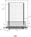
Fig. 1] Fig. 1 is a schematic top view of a transport device according to an embodiment. - [
Fig. 2] Fig. 2 is a schematic top view of the transport device according to the embodiment. - [
Fig. 3] Fig. 3 is a schematic side view of the transport device according to the embodiment. - [
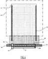
Fig. 4] Fig. 4 is a schematic top view of the transport device according to the embodiment. - [
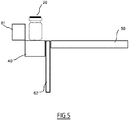
Fig. 5] Fig. 5 is a schematic side view of the transport device according to the embodiment. - [
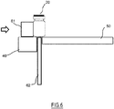
Fig. 6] Fig. 6 is a schematic side view of the transport device according to the embodiment. - [
Fig. 7] Fig. 7 is a schematic top view of the transport device according to the embodiment. - [
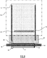
Fig. 8] Fig. 8 is a schematic top view of the transport device according to the embodiment. - [
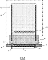
Fig. 9] Fig. 9 is a schematic top view of the transport device according to the embodiment. - [
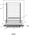
Fig. 10] Fig. 10 is a schematic top view of the transport device according to the embodiment. - [
Fig. 11] Fig. 11 is a schematic top view of the transport device according to the embodiment. - [
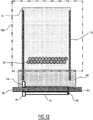
Fig. 12] Fig. 12 is a schematic top view of the transport device according to the embodiment. - [
Fig. 13] Fig. 13 is a schematic top view of the transport device according to the embodiment. - [
Fig. 14] Fig. 14 is a schematic top view of the transport device according to the embodiment. - An embodiment of the present invention will be described below. In the drawings, the same or similar parts are designated by the same or similar reference signs. However, the drawings are schematic illustrations. Therefore, specific dimensions or the like are to be determined based on the following description. In addition, the drawings may include parts having different dimensional relationships and ratios from each other as a matter of course.
- A transport device according to the embodiment includes, as illustrated in
Fig. 1 , aplate 50, aconveyor 40 disposed at a position adjacent to theplate 50 configured to transportarticles 20, apusher 61 configured to push a row of thearticles 20 on theconveyor 40 and transfer the row of thearticles 20 onto theplate 50, and astopper 60 configured to restrain the movement of thearticles 20 by theconveyor 40 and define a head of the row of thearticles 20 transferred onto theplate 50 by thepusher 61. In the transport device according to the embodiment, theconveyor 40 moves the positions of the rows of thearticles 20 stopped by thestopper 60 alternately such that the positions of the rows of thearticles 20 to be transferred onto theplate 50 are shifted alternately in a direction of the row. - The transport device according to the embodiment is arranged, for example, at a position adjacent to a
closed space 100 in which thearticles 20 are stored. As illustrated inFig. 2 , aplate 10 for placing thearticles 20 is arranged in theclosed space 100. Theclosed space 100 may be provided, for example, by an oven, a tank, a storage room, and the like. In theclosed space 100, at least one of a temperature and a pressure may be controlled. In the closedspace 100, at least one of temperature distribution and pressure distribution may be controlled. The oven may be a freeze dry oven. The closedspace 100 may be released by a door or the like. - Each of a plurality of the
articles 20 is, but not specifically limited, a container such as vials that stores pharmaceutical products to be subject, for example, to treatment such as freeze dry. Each of the plurality ofarticles 20 includes, for example, a cylindrical shape. The plurality ofarticles 20 are arranged in a staggered manner (staggered arrangement) in theclosed space 100 such that a larger number ofarticles 20 are arranged on theplate 10 in theclosed space 100. Therefore, the plurality ofarticles 20 are arranged in an overlapped manner when viewed from the side. The plurality ofarticles 20 are arranged such that centers are alternating with each other by row when viewed from above. - For example, the respective centers of the
articles 20 in a second row are shifted with respect to the respective centers of thearticles 20 in a first row in the direction of the row. However, the respective centers of thearticles 20 in a third row are not generally shifted with respect to the respective centers of thearticles 20 in the first row in the direction of the row. The centers of the plurality ofarticles 20 may be recognized as being arranged at intersections of a triangle grid pattern. However, in this disclosure, a triangle forming the triangle grid pattern may be, and may not be a regular triangle. - A
guide 70 may be provided in a vicinity of theplate 10 and theplate 50 to prevent thearticles 20 pushed by thepusher 61 from spreading laterally with respect to a direction of travel of thepusher 61. - The
plate 50 illustrated inFig. 1 may be part of a bridge to be disposed between theconveyor 40 and theplate 10 in theclosed space 100. Theconveyor 40 is capable of transporting thearticles 20 in a direction parallel to edges of theclosed space 100 and theplate 50. The transport device according to the embodiment further includes avertical gate 62 arranged between theplate 50 and theconveyor 40. Thevertical gate 62 is movable in a direction vertical to upper surfaces of theplate 50 and theconveyor 40. As illustrated inFig. 3 , thevertical gate 62 is moved upward to a level higher than the upper surfaces of theconveyor 40 and theplate 50 while theconveyor 40 transports thearticles 20 to prevent thearticles 20 from being transferred onto theplate 50. Thepusher 61 is located at a position which does not pose an impediment of transport of thearticles 20 while theconveyor 40 transports thearticles 20. Thepusher 61 and thevertical gate 62 function as a guide for thearticles 20 being transported. Theconveyor 40 illustrated inFig. 1 transports thearticles 20 stored in theclosed space 100 toward thestopper 60. Thearticles 20 are interposed between thepusher 61 and thevertical gate 62 and are transported toward thestopper 60. - As illustrated in
Fig. 4 , thestopper 60 comes into contact with the side surface of thearticle 20 to stop the movement of thearticles 20. The upper surface of theconveyor 40 continues to slide against bottom surfaces of the stoppedarticles 20 until theconveyor 40 is stopped. Followingarticles 20 transported by theconveyor 40 come into contact with theprecedent articles 20 stopped by thestopper 60 one after another and are stopped from moving. - The transport device according to the embodiment further includes a counting
sensor 63 configured to count the number of thearticles 20 transported by theconveyor 40, and anapproach gate 64 configured to restrain the movement of thearticles 20 on theconveyor 40 and define a terminal end of the row of thearticles 20 to be transferred onto theplate 50. Theapproach gate 64 is opened in the beginning. When the number of thearticles 20 counted by the countingsensor 63 reaches a predetermined number which corresponds to one row of thearticles 20 to be stored in theclosed space 100, the countingsensor 63 transmits a trigger signal to theapproach gate 64. Theapproach gate 64 that receives the trigger signal is closed. Therefore, the same number of thearticles 20 as the number of thearticles 20 in a row stored in theclosed space 100 enter between thestopper 60 and theclosed approach gate 64. Note that the head of the row of thearticles 20 may reach thestopper 60 after theapproach gate 64 is closed. Subsequently, theconveyor 40 stops driving. As illustrated inFig. 5 , thevertical gate 62 moves downward to a level lower than the upper surfaces of theconveyor 40 and theplate 50. - The
pusher 61 is movable in a direction vertical to the direction of movement of theconveyor 40 and in the direction parallel to the upper surface of theconveyor 40. As illustrated inFig. 6 andFig. 7 , thepusher 61 pushes the row of thearticles 20 on theconveyor 40 and transfers the row of thearticles 20 onto theplate 50 and theplate 10. The row of thearticles 20 transferred onto theplate 10 first in a state in which theclosed space 100 is empty corresponds to a first row of thearticles 20 to be pushed into theclosed space 100. Thestopper 60 may be fixed to thepusher 61 and move in association with the movement of thepusher 61. As illustrated inFig. 8 , after the row of thearticles 20 is transferred, thepusher 61 is retracted to a position which does not pose an impediment of transport of thearticles 20 by theconveyor 40. Thevertical gate 62 moves upward to a level higher than the upper surfaces of theconveyor 40 and theplate 50, and theapproach gate 64 is opened. - Subsequently, as illustrated in
Fig. 9 , theconveyor 40 transports thearticles 20, which correspond to thearticles 20 in a second row to be pushed into theclosed space 100, toward thestopper 60. Thehead article 20 comes into contact with thestopper 60 and is stopped. After theconveyor 40 transfers a predetermined number ofarticles 20, theapproach gate 64 is closed and theconveyor 40 stops driving. Note that the head of the row of thearticles 20 may reach thestopper 60 after theapproach gate 64 is closed. Subsequently, as illustrated inFig. 10 , theconveyor 40 retracts the row of thearticles 20 in a direction away from thestopper 60 generally by the same distance as the radius of thearticle 20. Subsequently, as illustrated inFig. 11 , thepusher 61 transfers the row of thearticles 20 on theconveyor 40 onto theplate 50 and theplate 10 at least until the articles come into contact with the first row of thearticles 20 on theplate 10. The respective centers of thearticles 20 in the second row are generally shifted in the direction of the row with respect to the respective centers of thearticles 20 in the first row by the same distance as the radius of thearticle 20. Subsequently, as illustrated inFig. 12 , thepusher 61 is retracted to a position which does not pose an impediment of transport of thearticles 20 by theconveyor 40. Thevertical gate 62 moves upward to a level higher than the upper surfaces of theconveyor 40 and theplate 50, and theapproach gate 64 is opened. - Subsequently, as illustrated in
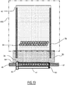
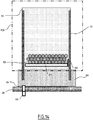
Fig. 13 , theconveyor 40 transports thearticles 20, which correspond to thearticles 20 in a third row to be pushed into theclosed space 100, toward thestopper 60. Thehead article 20 comes into contact with thestopper 60 and is stopped. After theconveyor 40 transfers a predetermined number ofarticles 20, theapproach gate 64 is closed and theconveyor 40 stops driving. Note that the head of the row of thearticles 20 may reach thestopper 60 after theapproach gate 64 is closed. Subsequently, as illustrated inFig. 14 , thepusher 61 transfers the row of thearticles 20 on theconveyor 40 onto theplate 50 and theplate 10 at least until the articles come into contact with the second row of thearticles 20 on theplate 50. The respective centers of thearticles 20 in the third row are not shifted in the direction of the row with respect to the respective centers of thearticles 20 in the first row. The respective centers of thearticles 20 in the third row are generally shifted in the direction of the row with respect to the respective centers of thearticles 20 in the second row by the same distance as the radius of thearticle 20. - From then onward, steps of retracting the
articles 20, which correspond to thearticles 20 in the rows with ordinals of odd numbers stopped by thestopper 60, by theconveyor 40 and then transferringsuch articles 20 onto theplate 50 and theplate 10 by thepusher 61; and transferring thearticles 20, which correspond to thearticles 20 in the row with ordinals of even numbers stopped by thestopper 60 onto theplate 50 and theplate 10 by thepusher 61 without retractingsuch articles 20 by theconveyor 40 are repeated. In this manner, the staggered arrangement of thearticles 20 in theclosed space 100 is achieved as illustrated inFig. 2 by moving the positions of the rows of thearticles 20 stopped by thestopper 60 alternately by theconveyor 40 such that the positions of the rows of thearticles 20 to be transferred onto theplate 50 are shifted alternately. After the staggered arrangement of a predetermined number of thearticles 20 in theclosed space 100, a door of the oven or the like that provides theclosed space 100 is closed. - In the related art, in order to achieve the staggered arrangement of the articles on the plate, the rows of the articles on the conveyor are moved in the direction of the row by using, for example, a drive unit other than the conveyor, such as a stopper, capable of moving in the direction of the row of the articles. In the closed space such as the freeze dry oven, a clean environment is desired. However, the drive unit may generate dust and thus the drive unit may become an origin of contamination in the closed space. Furthermore, the drive unit needs regular maintenance, which may increase costs of manufacturing the articles.
- In contrast, in the transport device according to the embodiment, the
conveyor 40 shifts the position of the row of thearticles 20 stopped by thestopper 60 alternately such that the positions of the row of thearticles 20 to be transferred onto theplate 50 are shifted alternately, and thus the provision of another drive unit for moving the row of the articles on theconveyor 40 in the direction of the row may be eliminated. Therefore, a degree of cleanliness of air around theclosed space 100 may be enhanced. In addition, by eliminating the provision of another drive unit for moving the row of the articles on theconveyor 40 in the direction of the row, reduction of the cost for manufacturing the transport device is achieved. Furthermore, by eliminating the provision of another drive unit for moving the row of the articles on theconveyor 40 in the direction of the row, reduction of the cost of maintenance of the transport device and the like is achieved. Therefore, reduction of the cost for manufacturing articles is also achieved. - Although the present invention has been described based on the embodiment, description and drawings which constitute part of this disclosure should not be interpreted to limit the present invention. From this disclosure, various alternative embodiments, examples, and operational technologies will become apparent for those skilled in the art. For example, an example in which the
articles 20 in the row with ordinals of even numbers stopped by thestopper 60 are retracted by theconveyor 40 without retracting thearticles 20 in the rows with ordinals of odd numbers stopped by thestopper 60 by theconveyor 40 has been described in the embodiment. In contrast, an example in which thearticles 20 in the rows with ordinals of odd numbers stopped by thestopper 60 may be retracted by theconveyor 40 without retracting thearticles 20 in the row with ordinals of even numbers stopped by thestopper 60 by theconveyor 40. In addition, articles to be transported in or out of the oven are not limited to those including the pharmaceutical products, but may be articles such as food products, beverages, and precision parts, and may include any articles. The oven is not limited to the freeze dry oven, and may be a fermentation oven, or any oven which requires restraint of unevenness in temperature distribution or restraint of generation of dust in the interior. Furthermore, while an example in which thestopper 60 is fixed to thepusher 61 has been described in the embodiment, thestopper 60 may be fixed onto theconveyor 40 instead of being fixed to thepusher 61. In this manner, it should be understood that the present invention includes various embodiments which are not described in this specification. - 10... plate, 20... article, 40... conveyor, 50... plate, 60... stopper, 61... pusher, 62... vertical gate, 63... counting sensor, 64... approach gate, 70... guide, 100... closed space
Claims (10)
- A transport device comprising:a plate;a conveyor configured to transport articles;a pusher configured to push a row of the articles on the conveyor and transfer the row of the articles onto the plate; anda stopper configured to restrain movement of the articles by the conveyor and define a head of the row of the articles to be transferred onto the plate by the pusher,wherein the conveyor moves positions of the rows of the articles stopped by the stopper alternately such that the positions of the rows of the articles transferred onto the plate are shifted alternately.
- The transport device according to Claim 1, further comprising a vertical gate disposed between the plate and the conveyor and configured to move upward to prevent the articles from being transferred onto the plate while the articles are moving on the conveyor and move downward while the row of the articles is being pushed by the pusher.
- The transport device according to Claim 1 or 2, further comprising an approach gate configured to restrain the movement of the articles on the conveyor and define a terminal end of the row of the articles to be transferred onto the plate.
- The transport device according to Claim 3, further comprising a counting sensor configured to count the number of the articles received between the stopper and the approach gate.
- The transport device according to Claim 4, wherein the approach gate is closed when the number of the articles reaches a predetermined number.
- The transport device according to Claim 1, wherein the stopper is fixed to the pusher.
- The transport device according to Claim 1, wherein the stopper is fixed onto the conveyor.
- The transport device according to any one of Claim 1 to Claim 7, wherein the conveyor retracts the position of the row of the articles stopped by the stopper every other time such that the positions of the rows of the articles transferred onto the plate are shifted alternately.
- The transport device according to Claim 8, wherein the articles have a circular cross section and the conveyor retracts the row of the articles by the same distance as a radius of the circle.
- A freeze dry system comprising:
a freeze dry oven in which a plate is disposed in an interior thereof;
a conveyor configured to transport articles;
a pusher configured to push a row of the articles on the conveyor and transfer the row of the articles onto the plate; and
a stopper configured to restrain movement of the articles by the conveyor and define a head of the row of the articles to be transferred onto the plate by the pusher,
wherein
the conveyor moves positions of the rows of the articles stopped by the stopper alternately such that the positions of the rows of the articles transferred onto the plate are shifted alternately.
Applications Claiming Priority (1)
| Application Number | Priority Date | Filing Date | Title |
|---|---|---|---|
| PCT/JP2018/015068 WO2019198148A1 (en) | 2018-04-10 | 2018-04-10 | Transport device and freeze-drying system |
Publications (3)
| Publication Number | Publication Date |
|---|---|
| EP3778440A1 true EP3778440A1 (en) | 2021-02-17 |
| EP3778440A4 EP3778440A4 (en) | 2021-11-24 |
| EP3778440B1 EP3778440B1 (en) | 2024-02-21 |
Family
ID=68164096
Family Applications (1)
| Application Number | Title | Priority Date | Filing Date |
|---|---|---|---|
| EP18914403.3A Active EP3778440B1 (en) | 2018-04-10 | 2018-04-10 | Transport device and freeze-drying system |
Country Status (4)
| Country | Link |
|---|---|
| US (1) | US11261034B2 (en) |
| EP (1) | EP3778440B1 (en) |
| CN (1) | CN112004761B (en) |
| WO (1) | WO2019198148A1 (en) |
Family Cites Families (17)
| Publication number | Priority date | Publication date | Assignee | Title |
|---|---|---|---|---|
| JPS4833587B1 (en) * | 1969-12-19 | 1973-10-15 | ||
| SE385566B (en) | 1973-05-16 | 1976-07-12 | J Nordqvist | SUBJECT TO WHEN PACKING A NUMBER, IN CROSS-SIGNIFICANTLY ROUND FOREMAL, PLACE THESE IN A MAINLY PARALLEL-PIPEDIC FORMATION WITH THE FOREMAL ORGANIZED IN SKRA JEMTE DEVICE FOR PERFORMING THE SET |
| SU1093623A1 (en) * | 1983-03-10 | 1984-05-23 | Проектно-конструкторское бюро Гусевского филиала Государственного научно-исследовательского института стекла | Apparatus for grouping cylindrical piece articles in checked arrangement |
| JPS613204U (en) | 1984-06-11 | 1986-01-10 | 大味株式会社 | Staggered alignment device |
| JPS63235214A (en) * | 1988-03-11 | 1988-09-30 | Yamanouchi Pharmaceut Co Ltd | Freeze dryer |
| US5472077A (en) * | 1995-01-09 | 1995-12-05 | I.M.T.E.C. Enterprises, Inc. | Article transfer apparatus |
| JP2966767B2 (en) | 1995-06-09 | 1999-10-25 | 古河電池株式会社 | Boxing device for cylindrical batteries |
| EP2425867A3 (en) * | 2001-12-28 | 2012-09-19 | Terumo Kabushiki Kaisha | Syringe |
| JP4574326B2 (en) | 2004-11-04 | 2010-11-04 | 東芝三菱電機産業システム株式会社 | Vial supply device |
| JP4690269B2 (en) | 2006-08-11 | 2011-06-01 | 株式会社エヌテック | Container row transfer device and container row transfer method |
| CN201089527Y (en) * | 2007-07-09 | 2008-07-23 | 比亚迪股份有限公司 | Automatic box packing device |
| DE102010047744A1 (en) | 2010-10-11 | 2012-04-12 | Martin Christ Gefriertrocknungsanlagen Gmbh | Loading and unloading device for a freeze-drying plant |
| CN105438537A (en) * | 2015-12-25 | 2016-03-30 | 长沙知元科技有限公司 | Packaging equipment and grouping device and method thereof |
| CN205555439U (en) * | 2015-12-31 | 2016-09-07 | 天津曼科科技有限公司 | Storage conveyer |
| CN105857729B (en) * | 2016-05-04 | 2019-06-25 | 中粮包装(天津)有限公司 | A kind of aerosol cans sorting and packing equipment |
| CN107128667B (en) * | 2017-03-29 | 2019-02-12 | 浙江大学 | A fully automatic stacking equipment suitable for cans of different specifications |
| CN107777346B (en) * | 2017-09-28 | 2019-11-01 | 苏州天源磁业股份有限公司 | A kind of diamond shape magnetic core misplaces solid matter method and device automatically |
-
2018
- 2018-04-10 EP EP18914403.3A patent/EP3778440B1/en active Active
- 2018-04-10 US US17/043,085 patent/US11261034B2/en active Active
- 2018-04-10 CN CN201880092024.0A patent/CN112004761B/en active Active
- 2018-04-10 WO PCT/JP2018/015068 patent/WO2019198148A1/en not_active Ceased
Also Published As
| Publication number | Publication date |
|---|---|
| CN112004761B (en) | 2022-08-09 |
| US20210016977A1 (en) | 2021-01-21 |
| US11261034B2 (en) | 2022-03-01 |
| EP3778440A4 (en) | 2021-11-24 |
| WO2019198148A1 (en) | 2019-10-17 |
| CN112004761A (en) | 2020-11-27 |
| EP3778440B1 (en) | 2024-02-21 |
Similar Documents
| Publication | Publication Date | Title |
|---|---|---|
| CN108146948B (en) | Method for depositing and removing objects and storage system for carrying out the method | |
| EP2706027B1 (en) | Product handling system and carrier device | |
| EP2799886B1 (en) | Cuvette handling device | |
| US7100792B2 (en) | Automatic apparatus for storing and dispensing packaged medication and other small elements | |
| US11597549B2 (en) | Bottle tray and storage station | |
| US7941990B2 (en) | Apparatus for packaging products into a container | |
| US9586769B2 (en) | System and method for forming and moving an article array | |
| CN113165818A (en) | Storage container for automated storage and retrieval system | |
| CN113286745A (en) | Method for transferring and packaging articles and device for carrying out said method | |
| CA2956087A1 (en) | Apparatus for transporting a container relative to a filling station | |
| US10144596B2 (en) | System and method for forming and moving an article array | |
| US3682338A (en) | Combination depalletizer and palletizer | |
| US20130185952A1 (en) | Loading and/or unloading device for a freeze drying system | |
| EP3450362B1 (en) | Device for loading a group of products on a pallet | |
| US20190031378A1 (en) | Loading device and method for loading storage and transport containers with plastic receptacles | |
| US20110308206A1 (en) | Packaging system for filling a collecting container with articles | |
| EP3778440B1 (en) | Transport device and freeze-drying system | |
| US10897911B2 (en) | Dispensing unit for baked products | |
| US8863936B2 (en) | Apparatus for transporting packagings that are not freely stackable, in particular stickpacks, to a transport container | |
| US20210163234A1 (en) | Transport device and furnace system | |
| AU2023238615A1 (en) | Method and device for moving goods with a load carrier | |
| US11097905B2 (en) | Transport device | |
| JP7347972B2 (en) | Transshipment equipment | |
| EP4429982B1 (en) | Cases grouping and transfer unit for case packer machines | |
| WO2019234644A1 (en) | Unloader of rod-like articles of the tobacco industry |
Legal Events
| Date | Code | Title | Description |
|---|---|---|---|
| STAA | Information on the status of an ep patent application or granted ep patent |
Free format text: STATUS: THE INTERNATIONAL PUBLICATION HAS BEEN MADE |
|
| PUAI | Public reference made under article 153(3) epc to a published international application that has entered the european phase |
Free format text: ORIGINAL CODE: 0009012 |
|
| STAA | Information on the status of an ep patent application or granted ep patent |
Free format text: STATUS: REQUEST FOR EXAMINATION WAS MADE |
|
| 17P | Request for examination filed |
Effective date: 20200928 |
|
| AK | Designated contracting states |
Kind code of ref document: A1 Designated state(s): AL AT BE BG CH CY CZ DE DK EE ES FI FR GB GR HR HU IE IS IT LI LT LU LV MC MK MT NL NO PL PT RO RS SE SI SK SM TR |
|
| AX | Request for extension of the european patent |
Extension state: BA ME |
|
| DAV | Request for validation of the european patent (deleted) | ||
| DAX | Request for extension of the european patent (deleted) | ||
| A4 | Supplementary search report drawn up and despatched |
Effective date: 20211022 |
|
| RIC1 | Information provided on ipc code assigned before grant |
Ipc: B65G 47/53 20060101ALI20211018BHEP Ipc: B65G 47/46 20060101AFI20211018BHEP |
|
| GRAP | Despatch of communication of intention to grant a patent |
Free format text: ORIGINAL CODE: EPIDOSNIGR1 |
|
| STAA | Information on the status of an ep patent application or granted ep patent |
Free format text: STATUS: GRANT OF PATENT IS INTENDED |
|
| INTG | Intention to grant announced |
Effective date: 20231024 |
|
| GRAS | Grant fee paid |
Free format text: ORIGINAL CODE: EPIDOSNIGR3 |
|
| GRAA | (expected) grant |
Free format text: ORIGINAL CODE: 0009210 |
|
| STAA | Information on the status of an ep patent application or granted ep patent |
Free format text: STATUS: THE PATENT HAS BEEN GRANTED |
|
| AK | Designated contracting states |
Kind code of ref document: B1 Designated state(s): AL AT BE BG CH CY CZ DE DK EE ES FI FR GB GR HR HU IE IS IT LI LT LU LV MC MK MT NL NO PL PT RO RS SE SI SK SM TR |
|
| REG | Reference to a national code |
Ref country code: GB Ref legal event code: FG4D |
|
| REG | Reference to a national code |
Ref country code: CH Ref legal event code: EP |
|
| REG | Reference to a national code |
Ref country code: DE Ref legal event code: R096 Ref document number: 602018065714 Country of ref document: DE |
|
| REG | Reference to a national code |
Ref country code: IE Ref legal event code: FG4D |
|
| REG | Reference to a national code |
Ref country code: LT Ref legal event code: MG9D |
|
| REG | Reference to a national code |
Ref country code: NL Ref legal event code: MP Effective date: 20240221 |
|
| PG25 | Lapsed in a contracting state [announced via postgrant information from national office to epo] |
Ref country code: IS Free format text: LAPSE BECAUSE OF FAILURE TO SUBMIT A TRANSLATION OF THE DESCRIPTION OR TO PAY THE FEE WITHIN THE PRESCRIBED TIME-LIMIT Effective date: 20240621 |
|
| PG25 | Lapsed in a contracting state [announced via postgrant information from national office to epo] |
Ref country code: LT Free format text: LAPSE BECAUSE OF FAILURE TO SUBMIT A TRANSLATION OF THE DESCRIPTION OR TO PAY THE FEE WITHIN THE PRESCRIBED TIME-LIMIT Effective date: 20240221 |
|
| PG25 | Lapsed in a contracting state [announced via postgrant information from national office to epo] |
Ref country code: GR Free format text: LAPSE BECAUSE OF FAILURE TO SUBMIT A TRANSLATION OF THE DESCRIPTION OR TO PAY THE FEE WITHIN THE PRESCRIBED TIME-LIMIT Effective date: 20240522 |
|
| REG | Reference to a national code |
Ref country code: AT Ref legal event code: MK05 Ref document number: 1658974 Country of ref document: AT Kind code of ref document: T Effective date: 20240221 |
|
| PG25 | Lapsed in a contracting state [announced via postgrant information from national office to epo] |
Ref country code: NL Free format text: LAPSE BECAUSE OF FAILURE TO SUBMIT A TRANSLATION OF THE DESCRIPTION OR TO PAY THE FEE WITHIN THE PRESCRIBED TIME-LIMIT Effective date: 20240221 Ref country code: RS Free format text: LAPSE BECAUSE OF FAILURE TO SUBMIT A TRANSLATION OF THE DESCRIPTION OR TO PAY THE FEE WITHIN THE PRESCRIBED TIME-LIMIT Effective date: 20240521 Ref country code: HR Free format text: LAPSE BECAUSE OF FAILURE TO SUBMIT A TRANSLATION OF THE DESCRIPTION OR TO PAY THE FEE WITHIN THE PRESCRIBED TIME-LIMIT Effective date: 20240221 |
|
| PG25 | Lapsed in a contracting state [announced via postgrant information from national office to epo] |
Ref country code: ES Free format text: LAPSE BECAUSE OF FAILURE TO SUBMIT A TRANSLATION OF THE DESCRIPTION OR TO PAY THE FEE WITHIN THE PRESCRIBED TIME-LIMIT Effective date: 20240221 |
|
| PG25 | Lapsed in a contracting state [announced via postgrant information from national office to epo] |
Ref country code: AT Free format text: LAPSE BECAUSE OF FAILURE TO SUBMIT A TRANSLATION OF THE DESCRIPTION OR TO PAY THE FEE WITHIN THE PRESCRIBED TIME-LIMIT Effective date: 20240221 |
|
| PG25 | Lapsed in a contracting state [announced via postgrant information from national office to epo] |
Ref country code: RS Free format text: LAPSE BECAUSE OF FAILURE TO SUBMIT A TRANSLATION OF THE DESCRIPTION OR TO PAY THE FEE WITHIN THE PRESCRIBED TIME-LIMIT Effective date: 20240521 Ref country code: NO Free format text: LAPSE BECAUSE OF FAILURE TO SUBMIT A TRANSLATION OF THE DESCRIPTION OR TO PAY THE FEE WITHIN THE PRESCRIBED TIME-LIMIT Effective date: 20240521 Ref country code: NL Free format text: LAPSE BECAUSE OF FAILURE TO SUBMIT A TRANSLATION OF THE DESCRIPTION OR TO PAY THE FEE WITHIN THE PRESCRIBED TIME-LIMIT Effective date: 20240221 Ref country code: LT Free format text: LAPSE BECAUSE OF FAILURE TO SUBMIT A TRANSLATION OF THE DESCRIPTION OR TO PAY THE FEE WITHIN THE PRESCRIBED TIME-LIMIT Effective date: 20240221 Ref country code: IS Free format text: LAPSE BECAUSE OF FAILURE TO SUBMIT A TRANSLATION OF THE DESCRIPTION OR TO PAY THE FEE WITHIN THE PRESCRIBED TIME-LIMIT Effective date: 20240621 Ref country code: HR Free format text: LAPSE BECAUSE OF FAILURE TO SUBMIT A TRANSLATION OF THE DESCRIPTION OR TO PAY THE FEE WITHIN THE PRESCRIBED TIME-LIMIT Effective date: 20240221 Ref country code: GR Free format text: LAPSE BECAUSE OF FAILURE TO SUBMIT A TRANSLATION OF THE DESCRIPTION OR TO PAY THE FEE WITHIN THE PRESCRIBED TIME-LIMIT Effective date: 20240522 Ref country code: FI Free format text: LAPSE BECAUSE OF FAILURE TO SUBMIT A TRANSLATION OF THE DESCRIPTION OR TO PAY THE FEE WITHIN THE PRESCRIBED TIME-LIMIT Effective date: 20240221 Ref country code: ES Free format text: LAPSE BECAUSE OF FAILURE TO SUBMIT A TRANSLATION OF THE DESCRIPTION OR TO PAY THE FEE WITHIN THE PRESCRIBED TIME-LIMIT Effective date: 20240221 Ref country code: BG Free format text: LAPSE BECAUSE OF FAILURE TO SUBMIT A TRANSLATION OF THE DESCRIPTION OR TO PAY THE FEE WITHIN THE PRESCRIBED TIME-LIMIT Effective date: 20240221 Ref country code: AT Free format text: LAPSE BECAUSE OF FAILURE TO SUBMIT A TRANSLATION OF THE DESCRIPTION OR TO PAY THE FEE WITHIN THE PRESCRIBED TIME-LIMIT Effective date: 20240221 |
|
| PG25 | Lapsed in a contracting state [announced via postgrant information from national office to epo] |
Ref country code: PL Free format text: LAPSE BECAUSE OF FAILURE TO SUBMIT A TRANSLATION OF THE DESCRIPTION OR TO PAY THE FEE WITHIN THE PRESCRIBED TIME-LIMIT Effective date: 20240221 Ref country code: PT Free format text: LAPSE BECAUSE OF FAILURE TO SUBMIT A TRANSLATION OF THE DESCRIPTION OR TO PAY THE FEE WITHIN THE PRESCRIBED TIME-LIMIT Effective date: 20240621 |
|
| PG25 | Lapsed in a contracting state [announced via postgrant information from national office to epo] |
Ref country code: SE Free format text: LAPSE BECAUSE OF FAILURE TO SUBMIT A TRANSLATION OF THE DESCRIPTION OR TO PAY THE FEE WITHIN THE PRESCRIBED TIME-LIMIT Effective date: 20240221 Ref country code: PT Free format text: LAPSE BECAUSE OF FAILURE TO SUBMIT A TRANSLATION OF THE DESCRIPTION OR TO PAY THE FEE WITHIN THE PRESCRIBED TIME-LIMIT Effective date: 20240621 Ref country code: PL Free format text: LAPSE BECAUSE OF FAILURE TO SUBMIT A TRANSLATION OF THE DESCRIPTION OR TO PAY THE FEE WITHIN THE PRESCRIBED TIME-LIMIT Effective date: 20240221 Ref country code: LV Free format text: LAPSE BECAUSE OF FAILURE TO SUBMIT A TRANSLATION OF THE DESCRIPTION OR TO PAY THE FEE WITHIN THE PRESCRIBED TIME-LIMIT Effective date: 20240221 |
|
| REG | Reference to a national code |
Ref country code: DE Ref legal event code: R081 Ref document number: 602018065714 Country of ref document: DE Owner name: AZBIL TELSTAR TECHNOLOGIES. S.L., ES Free format text: FORMER OWNER: AZBIL CORPORATION, TOKYO, JP Ref country code: DE Ref legal event code: R081 Ref document number: 602018065714 Country of ref document: DE Owner name: SYNTEGON TELSTAR TECHNOLOGIES, S.L.U., ES Free format text: FORMER OWNER: AZBIL CORPORATION, TOKYO, JP |
|
| PG25 | Lapsed in a contracting state [announced via postgrant information from national office to epo] |
Ref country code: DK Free format text: LAPSE BECAUSE OF FAILURE TO SUBMIT A TRANSLATION OF THE DESCRIPTION OR TO PAY THE FEE WITHIN THE PRESCRIBED TIME-LIMIT Effective date: 20240221 |
|
| PG25 | Lapsed in a contracting state [announced via postgrant information from national office to epo] |
Ref country code: SM Free format text: LAPSE BECAUSE OF FAILURE TO SUBMIT A TRANSLATION OF THE DESCRIPTION OR TO PAY THE FEE WITHIN THE PRESCRIBED TIME-LIMIT Effective date: 20240221 |
|
| PG25 | Lapsed in a contracting state [announced via postgrant information from national office to epo] |
Ref country code: EE Free format text: LAPSE BECAUSE OF FAILURE TO SUBMIT A TRANSLATION OF THE DESCRIPTION OR TO PAY THE FEE WITHIN THE PRESCRIBED TIME-LIMIT Effective date: 20240221 Ref country code: CZ Free format text: LAPSE BECAUSE OF FAILURE TO SUBMIT A TRANSLATION OF THE DESCRIPTION OR TO PAY THE FEE WITHIN THE PRESCRIBED TIME-LIMIT Effective date: 20240221 |
|
| PG25 | Lapsed in a contracting state [announced via postgrant information from national office to epo] |
Ref country code: SK Free format text: LAPSE BECAUSE OF FAILURE TO SUBMIT A TRANSLATION OF THE DESCRIPTION OR TO PAY THE FEE WITHIN THE PRESCRIBED TIME-LIMIT Effective date: 20240221 |
|
| PG25 | Lapsed in a contracting state [announced via postgrant information from national office to epo] |
Ref country code: SM Free format text: LAPSE BECAUSE OF FAILURE TO SUBMIT A TRANSLATION OF THE DESCRIPTION OR TO PAY THE FEE WITHIN THE PRESCRIBED TIME-LIMIT Effective date: 20240221 Ref country code: SK Free format text: LAPSE BECAUSE OF FAILURE TO SUBMIT A TRANSLATION OF THE DESCRIPTION OR TO PAY THE FEE WITHIN THE PRESCRIBED TIME-LIMIT Effective date: 20240221 Ref country code: RO Free format text: LAPSE BECAUSE OF FAILURE TO SUBMIT A TRANSLATION OF THE DESCRIPTION OR TO PAY THE FEE WITHIN THE PRESCRIBED TIME-LIMIT Effective date: 20240221 Ref country code: EE Free format text: LAPSE BECAUSE OF FAILURE TO SUBMIT A TRANSLATION OF THE DESCRIPTION OR TO PAY THE FEE WITHIN THE PRESCRIBED TIME-LIMIT Effective date: 20240221 Ref country code: DK Free format text: LAPSE BECAUSE OF FAILURE TO SUBMIT A TRANSLATION OF THE DESCRIPTION OR TO PAY THE FEE WITHIN THE PRESCRIBED TIME-LIMIT Effective date: 20240221 Ref country code: CZ Free format text: LAPSE BECAUSE OF FAILURE TO SUBMIT A TRANSLATION OF THE DESCRIPTION OR TO PAY THE FEE WITHIN THE PRESCRIBED TIME-LIMIT Effective date: 20240221 |
|
| PG25 | Lapsed in a contracting state [announced via postgrant information from national office to epo] |
Ref country code: MC Free format text: LAPSE BECAUSE OF FAILURE TO SUBMIT A TRANSLATION OF THE DESCRIPTION OR TO PAY THE FEE WITHIN THE PRESCRIBED TIME-LIMIT Effective date: 20240221 |
|
| REG | Reference to a national code |
Ref country code: DE Ref legal event code: R097 Ref document number: 602018065714 Country of ref document: DE |
|
| PG25 | Lapsed in a contracting state [announced via postgrant information from national office to epo] |
Ref country code: MC Free format text: LAPSE BECAUSE OF FAILURE TO SUBMIT A TRANSLATION OF THE DESCRIPTION OR TO PAY THE FEE WITHIN THE PRESCRIBED TIME-LIMIT Effective date: 20240221 |
|
| REG | Reference to a national code |
Ref country code: CH Ref legal event code: PL |
|
| PG25 | Lapsed in a contracting state [announced via postgrant information from national office to epo] |
Ref country code: LU Free format text: LAPSE BECAUSE OF NON-PAYMENT OF DUE FEES Effective date: 20240410 |
|
| PLBE | No opposition filed within time limit |
Free format text: ORIGINAL CODE: 0009261 |
|
| STAA | Information on the status of an ep patent application or granted ep patent |
Free format text: STATUS: NO OPPOSITION FILED WITHIN TIME LIMIT |
|
| REG | Reference to a national code |
Ref country code: BE Ref legal event code: MM Effective date: 20240430 |
|
| PG25 | Lapsed in a contracting state [announced via postgrant information from national office to epo] |
Ref country code: LU Free format text: LAPSE BECAUSE OF NON-PAYMENT OF DUE FEES Effective date: 20240410 |
|
| PG25 | Lapsed in a contracting state [announced via postgrant information from national office to epo] |
Ref country code: BE Free format text: LAPSE BECAUSE OF NON-PAYMENT OF DUE FEES Effective date: 20240430 |
|
| PG25 | Lapsed in a contracting state [announced via postgrant information from national office to epo] |
Ref country code: FR Free format text: LAPSE BECAUSE OF NON-PAYMENT OF DUE FEES Effective date: 20240421 |
|
| 26N | No opposition filed |
Effective date: 20241122 |
|
| GBPC | Gb: european patent ceased through non-payment of renewal fee |
Effective date: 20240521 |
|
| PG25 | Lapsed in a contracting state [announced via postgrant information from national office to epo] |
Ref country code: FR Free format text: LAPSE BECAUSE OF NON-PAYMENT OF DUE FEES Effective date: 20240421 Ref country code: BE Free format text: LAPSE BECAUSE OF NON-PAYMENT OF DUE FEES Effective date: 20240430 Ref country code: CH Free format text: LAPSE BECAUSE OF NON-PAYMENT OF DUE FEES Effective date: 20240430 |
|
| PG25 | Lapsed in a contracting state [announced via postgrant information from national office to epo] |
Ref country code: IE Free format text: LAPSE BECAUSE OF NON-PAYMENT OF DUE FEES Effective date: 20240410 |
|
| PG25 | Lapsed in a contracting state [announced via postgrant information from national office to epo] |
Ref country code: SI Free format text: LAPSE BECAUSE OF FAILURE TO SUBMIT A TRANSLATION OF THE DESCRIPTION OR TO PAY THE FEE WITHIN THE PRESCRIBED TIME-LIMIT Effective date: 20240221 |
|
| PG25 | Lapsed in a contracting state [announced via postgrant information from national office to epo] |
Ref country code: GB Free format text: LAPSE BECAUSE OF NON-PAYMENT OF DUE FEES Effective date: 20240521 |
|
| PGFP | Annual fee paid to national office [announced via postgrant information from national office to epo] |
Ref country code: DE Payment date: 20250417 Year of fee payment: 8 |
|
| PGFP | Annual fee paid to national office [announced via postgrant information from national office to epo] |
Ref country code: IT Payment date: 20250430 Year of fee payment: 8 |
|
| PG25 | Lapsed in a contracting state [announced via postgrant information from national office to epo] |
Ref country code: CY Free format text: LAPSE BECAUSE OF FAILURE TO SUBMIT A TRANSLATION OF THE DESCRIPTION OR TO PAY THE FEE WITHIN THE PRESCRIBED TIME-LIMIT; INVALID AB INITIO Effective date: 20180410 |
|
| REG | Reference to a national code |
Ref country code: DE Ref legal event code: R081 Ref document number: 602018065714 Country of ref document: DE Owner name: SYNTEGON TELSTAR TECHNOLOGIES, S.L.U., ES Free format text: FORMER OWNER: AZBIL TELSTAR TECHNOLOGIES. S.L., TERRASSA, ES |
|
| PG25 | Lapsed in a contracting state [announced via postgrant information from national office to epo] |
Ref country code: HU Free format text: LAPSE BECAUSE OF FAILURE TO SUBMIT A TRANSLATION OF THE DESCRIPTION OR TO PAY THE FEE WITHIN THE PRESCRIBED TIME-LIMIT; INVALID AB INITIO Effective date: 20180410 |