EP3778402B1 - Pusher turboprop powerplant installation - Google Patents
Pusher turboprop powerplant installation Download PDFInfo
- Publication number
- EP3778402B1 EP3778402B1 EP20191228.4A EP20191228A EP3778402B1 EP 3778402 B1 EP3778402 B1 EP 3778402B1 EP 20191228 A EP20191228 A EP 20191228A EP 3778402 B1 EP3778402 B1 EP 3778402B1
- Authority
- EP
- European Patent Office
- Prior art keywords
- engine
- duct
- air inlet
- air
- gas turbine
- Prior art date
- Legal status (The legal status is an assumption and is not a legal conclusion. Google has not performed a legal analysis and makes no representation as to the accuracy of the status listed.)
- Active
Links
Images


Classifications
-
- B—PERFORMING OPERATIONS; TRANSPORTING
- B64—AIRCRAFT; AVIATION; COSMONAUTICS
- B64D—EQUIPMENT FOR FITTING IN OR TO AIRCRAFT; FLIGHT SUITS; PARACHUTES; ARRANGEMENT OR MOUNTING OF POWER PLANTS OR PROPULSION TRANSMISSIONS IN AIRCRAFT
- B64D27/00—Arrangement or mounting of power plants in aircraft; Aircraft characterised by the type or position of power plants
- B64D27/02—Aircraft characterised by the type or position of power plants
- B64D27/10—Aircraft characterised by the type or position of power plants of gas-turbine type
- B64D27/12—Aircraft characterised by the type or position of power plants of gas-turbine type within, or attached to, wings
-
- B—PERFORMING OPERATIONS; TRANSPORTING
- B64—AIRCRAFT; AVIATION; COSMONAUTICS
- B64D—EQUIPMENT FOR FITTING IN OR TO AIRCRAFT; FLIGHT SUITS; PARACHUTES; ARRANGEMENT OR MOUNTING OF POWER PLANTS OR PROPULSION TRANSMISSIONS IN AIRCRAFT
- B64D27/00—Arrangement or mounting of power plants in aircraft; Aircraft characterised by the type or position of power plants
- B64D27/02—Aircraft characterised by the type or position of power plants
- B64D27/10—Aircraft characterised by the type or position of power plants of gas-turbine type
- B64D27/14—Aircraft characterised by the type or position of power plants of gas-turbine type within, or attached to, fuselages
-
- B—PERFORMING OPERATIONS; TRANSPORTING
- B64—AIRCRAFT; AVIATION; COSMONAUTICS
- B64D—EQUIPMENT FOR FITTING IN OR TO AIRCRAFT; FLIGHT SUITS; PARACHUTES; ARRANGEMENT OR MOUNTING OF POWER PLANTS OR PROPULSION TRANSMISSIONS IN AIRCRAFT
- B64D27/00—Arrangement or mounting of power plants in aircraft; Aircraft characterised by the type or position of power plants
- B64D27/40—Arrangements for mounting power plants in aircraft
- B64D27/402—Arrangements for mounting power plants in aircraft comprising box like supporting frames, e.g. pylons or arrangements for embracing the power plant
-
- B—PERFORMING OPERATIONS; TRANSPORTING
- B64—AIRCRAFT; AVIATION; COSMONAUTICS
- B64D—EQUIPMENT FOR FITTING IN OR TO AIRCRAFT; FLIGHT SUITS; PARACHUTES; ARRANGEMENT OR MOUNTING OF POWER PLANTS OR PROPULSION TRANSMISSIONS IN AIRCRAFT
- B64D33/00—Arrangement in aircraft of power plant parts or auxiliaries not otherwise provided for
- B64D33/02—Arrangement in aircraft of power plant parts or auxiliaries not otherwise provided for of combustion air intakes
-
- B—PERFORMING OPERATIONS; TRANSPORTING
- B64—AIRCRAFT; AVIATION; COSMONAUTICS
- B64D—EQUIPMENT FOR FITTING IN OR TO AIRCRAFT; FLIGHT SUITS; PARACHUTES; ARRANGEMENT OR MOUNTING OF POWER PLANTS OR PROPULSION TRANSMISSIONS IN AIRCRAFT
- B64D33/00—Arrangement in aircraft of power plant parts or auxiliaries not otherwise provided for
- B64D33/08—Arrangement in aircraft of power plant parts or auxiliaries not otherwise provided for of power plant cooling systems
-
- B—PERFORMING OPERATIONS; TRANSPORTING
- B64—AIRCRAFT; AVIATION; COSMONAUTICS
- B64F—GROUND OR AIRCRAFT-CARRIER-DECK INSTALLATIONS SPECIALLY ADAPTED FOR USE IN CONNECTION WITH AIRCRAFT; DESIGNING, MANUFACTURING, ASSEMBLING, CLEANING, MAINTAINING OR REPAIRING AIRCRAFT, NOT OTHERWISE PROVIDED FOR; HANDLING, TRANSPORTING, TESTING OR INSPECTING AIRCRAFT COMPONENTS, NOT OTHERWISE PROVIDED FOR
- B64F5/00—Designing, manufacturing, assembling, cleaning, maintaining or repairing aircraft, not otherwise provided for; Handling, transporting, testing or inspecting aircraft components, not otherwise provided for
- B64F5/10—Manufacturing or assembling aircraft, e.g. jigs therefor
-
- F—MECHANICAL ENGINEERING; LIGHTING; HEATING; WEAPONS; BLASTING
- F02—COMBUSTION ENGINES; HOT-GAS OR COMBUSTION-PRODUCT ENGINE PLANTS
- F02C—GAS-TURBINE PLANTS; AIR INTAKES FOR JET-PROPULSION PLANTS; CONTROLLING FUEL SUPPLY IN AIR-BREATHING JET-PROPULSION PLANTS
- F02C6/00—Plural gas-turbine plants; Combinations of gas-turbine plants with other apparatus; Adaptations of gas-turbine plants for special use
- F02C6/20—Adaptations of gas-turbine plants for driving vehicles
- F02C6/206—Adaptations of gas-turbine plants for driving vehicles the vehicles being airscrew driven
-
- F—MECHANICAL ENGINEERING; LIGHTING; HEATING; WEAPONS; BLASTING
- F02—COMBUSTION ENGINES; HOT-GAS OR COMBUSTION-PRODUCT ENGINE PLANTS
- F02C—GAS-TURBINE PLANTS; AIR INTAKES FOR JET-PROPULSION PLANTS; CONTROLLING FUEL SUPPLY IN AIR-BREATHING JET-PROPULSION PLANTS
- F02C7/00—Features, components parts, details or accessories, not provided for in, or of interest apart form groups F02C1/00 - F02C6/00; Air intakes for jet-propulsion plants
- F02C7/04—Air intakes for gas-turbine plants or jet-propulsion plants
- F02C7/05—Air intakes for gas-turbine plants or jet-propulsion plants having provisions for obviating the penetration of damaging objects or particles
- F02C7/052—Air intakes for gas-turbine plants or jet-propulsion plants having provisions for obviating the penetration of damaging objects or particles with dust-separation devices
-
- F—MECHANICAL ENGINEERING; LIGHTING; HEATING; WEAPONS; BLASTING
- F02—COMBUSTION ENGINES; HOT-GAS OR COMBUSTION-PRODUCT ENGINE PLANTS
- F02C—GAS-TURBINE PLANTS; AIR INTAKES FOR JET-PROPULSION PLANTS; CONTROLLING FUEL SUPPLY IN AIR-BREATHING JET-PROPULSION PLANTS
- F02C7/00—Features, components parts, details or accessories, not provided for in, or of interest apart form groups F02C1/00 - F02C6/00; Air intakes for jet-propulsion plants
- F02C7/12—Cooling of plants
- F02C7/14—Cooling of plants of fluids in the plant, e.g. lubricant or fuel
-
- B—PERFORMING OPERATIONS; TRANSPORTING
- B64—AIRCRAFT; AVIATION; COSMONAUTICS
- B64D—EQUIPMENT FOR FITTING IN OR TO AIRCRAFT; FLIGHT SUITS; PARACHUTES; ARRANGEMENT OR MOUNTING OF POWER PLANTS OR PROPULSION TRANSMISSIONS IN AIRCRAFT
- B64D33/00—Arrangement in aircraft of power plant parts or auxiliaries not otherwise provided for
- B64D33/02—Arrangement in aircraft of power plant parts or auxiliaries not otherwise provided for of combustion air intakes
- B64D2033/0246—Arrangement in aircraft of power plant parts or auxiliaries not otherwise provided for of combustion air intakes comprising particle separators
-
- B—PERFORMING OPERATIONS; TRANSPORTING
- B64—AIRCRAFT; AVIATION; COSMONAUTICS
- B64D—EQUIPMENT FOR FITTING IN OR TO AIRCRAFT; FLIGHT SUITS; PARACHUTES; ARRANGEMENT OR MOUNTING OF POWER PLANTS OR PROPULSION TRANSMISSIONS IN AIRCRAFT
- B64D33/00—Arrangement in aircraft of power plant parts or auxiliaries not otherwise provided for
- B64D33/02—Arrangement in aircraft of power plant parts or auxiliaries not otherwise provided for of combustion air intakes
- B64D2033/0266—Arrangement in aircraft of power plant parts or auxiliaries not otherwise provided for of combustion air intakes specially adapted for particular type of power plants
- B64D2033/0293—Arrangement in aircraft of power plant parts or auxiliaries not otherwise provided for of combustion air intakes specially adapted for particular type of power plants for turboprop engines
-
- F—MECHANICAL ENGINEERING; LIGHTING; HEATING; WEAPONS; BLASTING
- F05—INDEXING SCHEMES RELATING TO ENGINES OR PUMPS IN VARIOUS SUBCLASSES OF CLASSES F01-F04
- F05D—INDEXING SCHEME FOR ASPECTS RELATING TO NON-POSITIVE-DISPLACEMENT MACHINES OR ENGINES, GAS-TURBINES OR JET-PROPULSION PLANTS
- F05D2220/00—Application
- F05D2220/30—Application in turbines
- F05D2220/32—Application in turbines in gas turbines
- F05D2220/324—Application in turbines in gas turbines to drive unshrouded, low solidity propeller
-
- F—MECHANICAL ENGINEERING; LIGHTING; HEATING; WEAPONS; BLASTING
- F05—INDEXING SCHEMES RELATING TO ENGINES OR PUMPS IN VARIOUS SUBCLASSES OF CLASSES F01-F04
- F05D—INDEXING SCHEME FOR ASPECTS RELATING TO NON-POSITIVE-DISPLACEMENT MACHINES OR ENGINES, GAS-TURBINES OR JET-PROPULSION PLANTS
- F05D2260/00—Function
- F05D2260/98—Lubrication
-
- Y—GENERAL TAGGING OF NEW TECHNOLOGICAL DEVELOPMENTS; GENERAL TAGGING OF CROSS-SECTIONAL TECHNOLOGIES SPANNING OVER SEVERAL SECTIONS OF THE IPC; TECHNICAL SUBJECTS COVERED BY FORMER USPC CROSS-REFERENCE ART COLLECTIONS [XRACs] AND DIGESTS
- Y02—TECHNOLOGIES OR APPLICATIONS FOR MITIGATION OR ADAPTATION AGAINST CLIMATE CHANGE
- Y02T—CLIMATE CHANGE MITIGATION TECHNOLOGIES RELATED TO TRANSPORTATION
- Y02T50/00—Aeronautics or air transport
- Y02T50/60—Efficient propulsion technologies, e.g. for aircraft
Definitions
- the disclosure relates generally to turboprop powered aircraft and turboprop powerplants, and more particularly to pusher turboprop powerplant installations.
- Turboprop gas turbine engines are most commonly mounted to aircraft in a "tractor” (or “puller") configuration, whereby the engine is mounted with the propeller located forward of the engine (relative to a direction of travel of the aircraft) such that the aircraft is “pulled” through the air by the propeller.
- Turboprop engines may however also be mounted to an aircraft in a “pusher” configuration, whereby the engine is mounted with the propeller located behind the engine (relative to the direction of travel of the aircraft).
- pusher engines can be either wing mounted, mounted to the fuselage tail and/or to pylons on the aircraft.
- US2015/300265A1 discloses a gas turbine engine having a heat exchanger axially aligned with the engine core.
- a turboprop gas turbine engine adapted to be mounted to an aircraft according to claim 1.
- FIG. 1 illustrates an exemplary aircraft 10 to which one or more gas turbine engines 12 may be mounted.
- the gas turbine engines 12 are turboprops, and are mounted to the aircraft in pusher configurations, whereby the engine is mounted with the propeller 14 located behind the engine (relative to the direction of travel 15 of the aircraft 10 - also referred to herein and depicted in the drawings as the "pilot view” direction).
- the pusher turboprop gas turbine engines 12 (or simply “pusher engines") are mounted to the wings 17 of the aircraft.
- upstream and downstream as used herein, unless indicated otherwise, are understood to be relative to the direction of travel 15 of the aircraft (i.e. the "pilot view” direction). Similarly, the terms “forward” and “rearward” as used herein are also understood to be relative to the direction of travel 15 of the aircraft.
- Each pusher engine 12 as described herein will generally be referred to in the singular, however it is to be understood that two or more or each of such engines may be provided on the aircraft 10.
- Each pusher engine 12 defines a longitudinal axis LA (e.g., central axis).
- longitudinal axis LA may correspond to an axis of rotation of propeller 14 and/or longitudinal axis LA may correspond to an axis of rotation of a low-pressure spool and/or a high-pressure spool of a core 13 of the gas turbine engine 12.
- Each gas turbine engine 12 may be housed in a nacelle 16, serving as an aerodynamically-shaped covering for gas turbine engine 12.
- the pusher engine 12 accordingly includes an engine core 13 (including compressor(s) 22, combustor 24 and turbine(s) 26) and a reduction gearbox 38 which drives the propeller 14, which is located rearward of the gas turbine engine 12, relative to a direction of travel of the aircraft, as is the case for pusher-style engines.
- engine core 13 including compressor(s) 22, combustor 24 and turbine(s) 26
- reduction gearbox 38 which drives the propeller 14, which is located rearward of the gas turbine engine 12, relative to a direction of travel of the aircraft, as is the case for pusher-style engines.
- the pusher engines as described in further detail below are generally intended to be wing-mounted, in that the nacelle 16 and the engine 12 are mounted to, and overtop of, a wing 17 of the aircraft 10.
- the pusher turboprop engines and installations described herein may also be adapted for being mounted to the fuselage of the aircraft and/or to pylons mounted to the aircraft.
- the gas turbine engine 12 comprises an air intake 18 for channeling a flow of ambient air into gas turbine engine 12.
- Air intake 18 comprises intake inlet 20 that is generally forward-facing and, in at least one particular embodiment, may be substantially aligned with the longitudinal axis LA of the engine 12. In typical pusher installations, the air intake is often offset radially outwardly (e.g. downwardly) relative to the longitudinal axis LA of engine. In at least some of the embodiments described herein, however, the intake inlet 20 of the air intake 18 is substantially axially aligned with the gas turbine engine 12, thereby allowing for a slimmer (e.g. smaller diameter) nacelle 16. Intake inlet 20 may be generally forward-facing, so that ambient air ingested into the air intake 18 is directed rearward within the envelope of the nacelle and to the engine air inlet 21 of the engine 12.
- the pusher engine 12 may be of a type suitable for use in aircraft applications for subsonic flight generally comprising, in serial flow communication, air intake 18 through which ambient air is received, a compressor section 22 (which may be a multistage compressor) for pressurizing the air, a combustor 24 in which the compressed air is mixed with fuel and ignited for generating an annular stream of hot combustion gases, and turbine section 26 (which may be a multistage turbine) for extracting energy from the combustion gases.
- gas turbine engine 12 may have a dual-spool configuration but it is understood that gas turbine engine 12 may not be limited to such configuration.
- gas turbine engine 12 may comprise high-pressure spool 28 including one or more stages of multistage compressor 22 and one or more high-pressure turbines 30 of turbine section 26.
- Gas turbine engine 12 may also comprise low-pressure spool 32 including one or more stages of multistage compressor 22 and one or more low-pressure (i.e., power) turbines 34 of turbine section 26.
- Low-pressure spool 32 may be mechanically coupled to output shaft 36 via a reduction gearbox 38, to which the propeller 14 may be coupled.
- the air intake 18 of the pusher engine 12 includes a forward-facing intake inlet 20 receiving the ambient air, and an inlet duct 44 in fluid communication with the intake inlet 20 and extending downstream therefrom. More particularly, the air inlet duct 44 extends from the intake inlet 20 to the engine air inlet 21, such as to provide the main airflow into the core 13 of the engine 12.
- the air inlet duct 44 includes a first, or upstream, section 43 that extends immediately downstream of the intake inlet 20 and may be, in one particular embodiment, centrally located such that an intake axis IA defined by the intake inlet 20 is substantially concentric with the longitudinal axis LA of the engine 12.
- a second, or downstream, section 45 of the air inlet duct 44 terminates at the engine air inlet 21.
- this second downstream section 45 of the air inlet duct 44 may be bifurcated into two separate ducts 45' and 45".
- the two separate ducts 45' and 45" are bifurcated relative to a central vertical plane extending through the longitudinal engine axis LA. Accordingly, the outlets of each of these ducts 45' and 45" may thereby direct the inlet airflow into opposite sides of an annual quasi-scroll intake 49 that that feeds the engine air inlet 21.
- the downstream duct section 45 is bifurcated, thereby comprising the bifurcated duct portions 45' and 45" which are split at the top-dead-center (TDC) and may thus be located at 11 and 1 o'clock, for example.
- the bifurcated duct portions 45' and 45" of the downstream duct 45 feed air to the engine air inlet 21 at two circumferential locations, thereby partially wrapping around the annular engine inlet and thus forming a "quasi-scroll" type air inlet duct configuration.
- This quasi-scroll inlet configuration may contribute to ensuring relatively low losses and enable some ram recovery of the air entering the engine core 13.
- overall engine performance e.g. specific fuel consumption (SPC)
- SPC specific fuel consumption
- an additional air duct 47 (which may also be referred to herein as a "second air outlet duct” or simply as an “oil cooler duct”), directs a portion of the incoming cool air into an air-cooled-oil-cooler (ACOC) 50.
- the ACOC air duct 47 is fluidly connected to the air inlet duct 44 at a point thereon between the first, upstream, section 43, and the second, downstream, section 45. This connection point may also be located over the wing 17 and downstream (and axially aft) of an inertial particle separator duct 42, as will be described in further detail below.
- the air intake 18 therefore includes two separate outlet ducts, namely the main air inlet flow within the downstream duct section 45 of the air inlet duct 44, which directs a portion of the inlet airflow into the core 13 of the engine 12, and the ACOC air duct 47, which directs another portion of the incoming air into an air-cooled-oil-cooler (ACOC) 50.
- ACOC air-cooled-oil-cooler
- the portion of the inlet airflow directed to the engine core may be a major or majority portion of the incoming airflow, and the portion of the airflow directed into the ACOC 50 may be a small portion of the total incoming airflow.
- the air duct 47 directs a portion of the air flowing through the inlet duct 44 to the ACOC 50, and a remaining portion of the incoming air is directed through the downstream duct portion 45 to the engine core air inlet 21.
- the ACOC 50 may be located in-line within the ACOC air duct 47.
- the ACOC 50 is used to cool engine oil, by transferring the heat from the engine oil to the cooler air flowing through the second outlet duct 47. After flowing through the ACOC 50, the air (by then heated by the ACOC) can flow out of the second outlet duct 47 for ejection - either externally to atmosphere or within the nacelle 16 - or re-use for other purposes (e.g. ant-icing over nacelle or engine components.
- the second outlet duct 47 and the ACOC 50 that is fed by it are both located axially forward of the engine core 13 of the engine 12, but may be substantially aligned therewith (relative to the axis LA) such as to produce an overall relative "long and thin" envelope for the nacelle 16, which therefore has a relatively long forward "snout".
- the ACOC 50 and the air duct 47 feeding it may be axially located in line (or overtop of) the wings 17 of the aircraft, with the majority of the engine 12 and/or the center of the mass of the engine 12 being located axially after of the wings 17.
- the first, most upstream, section 43 of the inlet duct 44 of the air intake 18 is centrally located within the nacelle 16 relative to the engine centerline LA.
- intake axis IA of the first section 43 of the inlet duct 44 may be substantially coaxial with the main engine axis LA, as seen in Figs. 3A and 3B .
- the downstream duct section 45, and thus the bifurcated duct portions 45' and 45" may however be radially offset from the inlet duct 44 and thus the intake axis IA, extending up and radially outward (over the accessory gear box 11 which is also axially aligned with the engine axis LA in order to maintain a slim radial envelope) before redirecting radially inward to the engine air inlet 21.
- the turboprop engine 12 is a pusher engine with the propeller 14 located aft of the engine core 13 and having a front-facing air inlet 20
- the possible effect of foreign object damage (FOD) caused by particles (e.g. ice, debris, etc.) in the incoming air should be considered.
- the air intake 18 also optionally includes an inertial particle separator (or "IPS") 60.
- the IPS 60 is located upstream, and axially forward, of the engine air inlet 21, so as to prevent ingestion of ice, other particles and/or other FOD-causing objects into the engine.
- the terms “particles” or simply "FOD” may be used herein to describe generally all of such FOD particles/objects, even though it will be understood that in some cases the FOD-causing objects in question may be significantly larger than an ice or other particle per se - such as a bird or other airborne object for example that could be unintentionally ingested into the engine's air intake.
- the IPS 60 is also located upstream, and axially forward, of the ACOC 50.
- the IPS 60 includes an IPS duct 64 that is fluidly connected with the upstream section 43 of the air inlet duct 44, and a FOD particle separator that is capable of separating FOD particles from the incoming airflow and re-directing them into the IPS duct 64. Accordingly, such undesirable FOD particles prevented from flowing unhindered downstream, through the air inlet duct 44 and thus into the air inlet of the engine 12.
- the IPS 60 includes a one or more FOD-deflectors, or FOD-diverters, that extend at least partially into the air inlet duct and act to redirect any FOD into the IPS duct 64.
- the FOD-deflectors comprise one or more FOD-diverting plates 62 (or simply “plates” hereinbelow) which project into the upstream section 43 of the air inlet duct 44, at a location upstream of the IPS duct 64.
- the FOD diverting plates 62 which in the depicted embodiment include three plates however fewer or more plates may alternately be used, may be either stationary or movable such as to be adjusted into a desired position relative to one another and relative to the incoming airflow through the inlet duct 44.
- the plate is displaceable between a deployed position and a retracted position. In the deployed position, the plate will protrude into the air inlet duct to redirect FOD. In the retracted position, the plate is substantially withdrawn from the airflow through the air inlet duct and will therefor generate less flow restriction.
- the moveable plate may be positioned not just at these two end points of its travel, i.e. at the fully retracted and fully deployed position, but may also be positioned a number of possible intermediate positions between these two extremes.
- each of the three plates 62 may be independent movable, and each may comprise either a two-state active control (e.g. being either deployed or retracted, as needed) or a fully variable active control whereby any desired angular position of each of the plates can be selected as required.
- the plates 62 are positioned such as to divert any potential FOD-causing particles that might enter the inlet duct 44 into the IPS duct 64, for subsequent discharge overboard. Unwanted FOD-causing particles are therefore diverted into the IPS duct 64, and prevented from flowing further downstream and thus from being ingested into the engine air inlet 21 or the ACOC 50.
- a plurality of plates 62 are provided and extend into the air inlet duct 44, with at least a first one of the plurality of plates extending away from an inner wall of the air inlet duct in a downstream direction, and at least a second one of the plurality of plates extending from an inner wall of the air inlet duct in an upstream direction.
- the plate which is more downstream within the air inlet duct will be the one which extends in the upstream direction away from the wall of the air inlet duct.
- These first and second ones of the plates may be mounted to the same inner wall of the air inlet duct, or may be located on opposite sides from each other with the duct.
- the IPS duct 64 may therefore be integrated with the inlet duct 44, and it projects away therefrom downward and radially away from the inlet axis IA.
- the IPS duct 64 in this embodiment is separate and distinct from, and located upstream of, the second outlet duct 47 feeding air to the ACOC 50.
- the IPS duct 64 may thus be axially located forward of the wing 17 of the aircraft, such as to expel any unwanted FOD particles outboard and away from the aerodynamic surfaces of the wings 17.
- the second outlet duct 44 and the ACOC 50 in this embodiment, are axially positioned over the wing 17, with the engine core 13 of the gas turbine engine 12 being located substantially rearward of the wing 17.
- the pusher engine 112 includes an air intake 118 in which the IPS duct and the ACOC duct are integrated into a single air duct 164, which is connected to the main air inlet duct 144 such as to divert a portion of the flow therethrough.
- the IPS duct 164 of the present air intake configuration includes the ACOC 50 therein, thereby avoiding the need for an additional air duct exclusively for the ACOC.
- the combined IPS and ACOC duct 164 is located forward of the wing 17 of the aircraft.
- the air inlet duct 144 is not bifurcated at TDC, as can be best seen in Fig. 4B .
- the downstream section 145 of the air inlet duct 144 therefore connects to the engine air inlet quasi-scroll 49 at a single location, for example at TDC.
- the engine air inlet is therefore a single inlet, quasi-scroll configuration.
- the pusher engine 212 includes an air intake 218 which is formed such that the overall axial length of the nacelle 216 required is shorter than that of the engines 12 and 112, thereby providing a so-called "medium snout" nacelle design, as opposed to the longer nacelle snouts of engines 12, 112.
- the air intake 218 includes an integrated IPS and ACOC duct 264 that includes the ACOC 50.
- the IPS 260 employs one or more fixed elements projecting into the upstream portion 243 of the main air inlet duct 244.
- the one or more fixed elements may include a fixed icing screen, which will capture ice particles within the incoming airflow.
- the fixed icing screen 262 may be part of a two state, passive system, rather than the active systems of the movable plates 62 described above.
- Inlet screens as described herein may comprise a metallic screen acts in operation to substantially prevent foreign objects (e.g., pieces of ice) larger than a certain size from exiting intake outlet.
- the screen(s) may also serve as a surface on which ice is permitted to accrete, thereby preventing or reducing the likelihood of ice accreting further downstream into gas turbine engine.
- the pusher engine 312 includes an air intake 318 which is even further simplified, in that it includes no fixed icing screen or other projecting plates as part of an IPS. Much as per the air intakes 118 and 218, the air intake 318 similarly includes an integrated IPS and ACOC duct 364 that includes the ACOC 50.
- the pusher engine 412 includes an air intake 418 which is similar to that of air intake 18 described above, in that it includes a separate IPS duct 464 and ACOC duct 447. In this embodiment, however, no IPS plates or other icing screens (fixed or otherwise) are provided as part of an IPS system.
- the pusher engine 512 includes an air intake 518 that includes both an IPS duct 564 and an ACOC duct 547.
- the ACOC duct 547 is not integrated with or connected directly to the main air inlet duct 544 feeding the air to the engine core. Rather, the ACOC duct 547 containing the ACOC 50 is mounted separately within the nacelle 516, over the wing 17, and receives incoming airflow from air flowing through the nacelle 16.
- the air directed through the ACOC duct 547 is not air which is diverted off from the main air inlet flow to the engine core. All of the air entering the front-facing air inlet 20 is therefore directed through the air inlet duct 544 to the engine air inlet 21.
- Fig. 9 depicts another unclaimed example, similar to that of Fig. 8 , except wherein the ACOC duct 647 is mounted below the wing 17, instead of above it. As such, the air directed through the ACOC duct 647 can be drawn from outside the nacelle 616 through inlet 650. However, in an alternate unclaimed example, the inlet 650 of the ACOC duct 647 may still be located such as to dawn air from outside the nacelle 616, however with the ACOC duct 647 located elsewhere within the nacelle.
- Figs. 10-12 depict alternate unclaimed examples, wherein the ACOC duct is disposed in other locations within the nacelle, generally aft of the wing of the aircraft.
- the ACOC duct may similarly be separate from ( Figs. 10 and 11 ) or integrated with ( Fig. 12 ) the IPS duct.
- Fig. 13 depicts an alternate unclaimed example, similar to that of Fig. 8 , except having an air inlet plenum (or "dump box”) at the engine air inlet, rather than the quasi-scroll air inlet configuration.
- air inlet plenum or "dump box”
- the pusher engine 612 includes an air intake 618 that includes an IPS duct 664 that and an ACOC duct 647.
- the IPS duct 64 is fluidly connected with the upstream section 643 of the air inlet duct 644, and a FOD particle separator that is capable of separating FOD particles from the incoming airflow and re-directing them into the IPS duct 664, for ejection overboard at 690. Accordingly, such undesirable FOD particles are prevented from flowing unhindered downstream, through the air inlet duct 644 and thus into the air inlet 21 of the engine 612.
- the air intake 620 and the upstream section 643 of the air intake 618 is located near the upper portion of the nacelle, and is not axially aligned with the engine. More particularly, the air intake 618 of the upstream section 643 of the air inlet duct 618 defines an intake axis IA that is radially offset (parallel to and spaced apart) from the from the main engine axis LA, as can be seen in Fig. 14 .
- the ACOC duct 647 is split apart from the IPS duct 664 and the rest of the air inlet duct 644 of the air intake 618.
- the ACOC duct 647 is located, in this unclaimed example, below the engine core, and draws air directly from outside the engine and/or outside the nacelle, for feeding through the ACOC in the ACOC duct 647. Accordingly, the airflow used to cool the ACOC, which flows through the ACOC duct 647, is independent from the airflow through the air intake 618, which feeds the engine.
- Fig. 15 depicts an alternate unclaimed example, similar to that of Fig. 14 , having an ACOC duct 747 that is split apart from the IPS duct 764 and the rest of the air inlet duct 744 of the air intake 718.
- the ACOC duct 747 is located above the engine core, rather than below, and is axially located rearward of the IPS duct 764 and the air intake 718. Nevertheless, the airflow feeds to the air intake 718 and the ACOC duct 747 are separate, and each draws ambient air in from different external inlets in the nacelle.
- the air intake may channel the flow of ambient air (represented by the arrow F in the figures) toward engine inlet of gas turbine engine.
- the engine inlet may have a substantially annular shape and may be disposed upstream of compressor 22 of the engine.
- the air intake may define an intake axis IA, which in certain embodiments may be substantially coaxial with annular engine inlet and/or substantially coaxial with longitudinal axis LA (e.g., center line) of gas turbine engine when air intake is installed on gas turbine engine.
- the engine inlet may comprise an annular opening into which the flow of air discharged substantially axially rearwardly from intake outlet.
- the annular engine inlet may be coaxial with longitudinal axis LA of gas turbine engine.
- the longitudinal axis LA of gas turbine engine may correspond to the axis or rotation of high-pressure spool 28 and of low-pressure spool 32 as shown in FIG. 3A . Accordingly, in embodiments where an axis of rotation of propeller 14 is radially offset from an axis of rotation of high-pressure spool 28 and low-pressure spool 32, the longitudinal axis LA may not necessarily correspond to the axis of rotation of propeller 14.
- the intake axis IA may be either substantially coaxial the longitudinal axis LA, or may be offset therefrom (e.g. spaced apart therefrom in a radial or transverse direction from the longitudinal axis).
- the annual quasi-scroll intake 49 that that feeds the engine air inlet 21, as described above with reference to Fig. 3A may be in fluid communication with intake duct 44 and receive the flow of air F from intake duct 44.
- a scroll portion of the quasi-scroll intake 49 may channel the flow of air F toward engine inlet via the intake outlet.
- the scroll portion may define one or more converging quasi scroll-shaped passages formed such as to cause acceleration and redirection of the flow of air F toward engine inlet with relatively low energy losses and pressure distortion.
- Air intakes may be installed on gas turbine engine and used to channel a flow of air to engine inlet with relatively low energy losses and flow distortion (e.g., swirl and pressure distortions).
- Air intake may define a generally streamlined flow path between intake inlet and the intake outlet.
- air intake may not comprise a plenum (i.e., dump box) often found in traditional air intakes and which may cause significant energy losses.
- improvements of flow characteristics of the flow or air F may improve engine performance in comparison with some other traditional air intakes.
- the air intakes as described herein may be fabricated according to known or other manufacturing methods using suitable sheet metal or polymeric material.
- air intake or part(s) thereof may be cast using a suitable metallic material or molded from a suitable polymeric material.
- air intake may comprise a plurality of components (e.g., pieces of sheet metal) pieced (e.g., welded) together to form air intake.
- an accessory gearbox 11 is in driving engagement with the low-pressure spool 32 ( Fig. 3A ) of the engine 12.
- the accessory gearbox (AGB) 11 defines at least one, three in the unclaimed example shown, outputs 11a for accessories (not shown) to be drivingly engaged to the low-pressure spool 32 via the accessory gearbox 11.
- the outputs 11a face a direction having a radial component relative to the longitudinal axis LA of the engine core 13.
- the accessories connected to the outputs 11a are herein located radially between the nacelle 16 and the outputs 11a.
- the disclosed pusher engine 12 allows the accessories to be located radially outwardly of the gearbox 11 and radially inwardly of the nacelle 16 relative to the axis LA. Consequently, an access door 16a of the nacelle 16 may allow easy access via an opening 16b defined through the nacelle 16 to replace, repair, and perform maintenance of the accessories without having to dismantle the pusher engine 12.
- a mounting structure M is used to secure the engine core 13 to the wing 17.
- the mounting structure includes a frame 100.
- the frame 100 is herein secured to both of fore and aft spars 17a, 17b of the wing 17.
- the fore and aft spars 17a, 17b are structural members that extend in a spanwise direction along a spanwise axis SA of the wing 17, from a root of the wing 17 to a tip thereof.
- the fore spar 17a is located proximate a leading edge of the wing 17 whereas the aft spar 17b is located proximate a trailing edge of the wing 17.
- the frame 100 includes a plurality of members 100a that are secured to one another.
- the members 100a are assembled to define an engine-receiving space S sized to contain the engine core 13 and the AGB 11.
- the members 100a may be tubular members.
- the engine core 13 is installed by moving said engine core in a vertical direction VD relative to a ground G.
- the vertical direction may correspond to a radial direction relative to the longitudinal axis LA of the engine core 13.
- the engine core 13 is inserted in the desired position by decreasing an elevation of the engine core 13 relative to the ground G. In other words, the engine core 13 is lowered into the desired position into the engine-receiving space S by bringing the engine core 13 closer to the ground G.
- the frame 100 has an upper frame portion 100b and a lower frame portion 100c both including some of the tubular members 100a.
- the mounting structure M further includes a mount ring 102 for connecting the engine core 13 to the frame 100.
- Each of the upper and lower frame portions 100b, 100c is secured to a respective one of upper and lower U-shaped mounts 102a, 102b of the mount ring 102.
- the U-shaped mounts are also referred to as horseshoe-shaped mount.
- Both of the U-shaped mounts 102a, 102b have a U-shape circumferentially extending around the engine core 13 relative to the longitudinal axis LA.
- the lower frame portion 100c and the lower U-shaped mount 102b are secured to the wing 17 via the fore and aft spars 17a, 17b whereas the upper frame portion 100b and the upper U-shaped mount 102a are secured to the engine core 13 prior to moving the engine core 13 in the desired position.
- the lower U-shaped mount 102b defines an opening O oriented away from the ground G when the aircraft is on the ground G.
- the upper and lower frame portions 100b, 100c may be securable to one another and the upper and lower U-shaped mounts 102a, 102b may be securable to one another once the engine core 13 and AGB 11 are in the desired position, within the engine-receiving space S.
- the engine core 13 includes a plurality of pads 13a that are circumferentially distributed around the longitudinal axis LA.
- the pads 13a are herein secured to a gas generator case 13b of the engine core 13.
- the gas generator case 13b is a case that surrounds the combustor 24 of the engine core 13. It will be appreciated that the pads 13a may be secured to the compressor case and/or to the turbine-exhaust case.
- the engine core 13 may be secured to the U-shaped mounts 102a, 102b and the frame 100 via any suitable case of the engine core 13.
- Elastomeric material may be located between the upper and lower U-shaped mounts 102a, 102b and the pads 13a for dampening vibrations occurring with operation of the gas turbine engine 12.
- the mounting structure S is secured to the wing 17 of the aircraft 10; the engine core 13 is inserted within the engine-receiving space S by changing the elevation of the engine core 13 relative to the ground G until the engine core 13 is at least partially enclosed by the lower U-shaped mount 102b; and the engine core 13 is secured to the lower U-shaped mount 102b.
- the lower frame portion 100c is secured to the wing 17; the lower U-shaped mount 102b is secured to the lower frame portion 100c; the upper frame portion 100b and the upper U-shaped mount 102a are secured to the engine core 13; and the engine core 13 is inserted into the engine-receiving space S by moving the engine core 13 in the vertical direction VD toward the ground G until the engine core 13 is received within the lower U-shaped mount 102b via its opening O facing away from the ground G.
- the upper and lower U-shaped mounts 102a, 102b may be secured to one another and the upper and lower frame portions 100c, 100d, may be secured to one another.
- the mounting structure includes only one U-shaped mount 104 defining an opening O' facing toward the ground G.
- the engine core 13 is receivable within the engine-receiving space S in an upward direction away from the ground G.
- the engine core 13 is elevated away from the ground G until the engine core 13 is at least partially enclosed by the U-shaped mount 104. At which point, the engine core 13 is secured to the U-shaped mount 104 via the pads 13a secured to the gas generator case 13b.
- the engine core 13 may be inserted in the engine-receiving space S without having to mount any frame portion thereto.
- a frame may include only a single portion that is secured to the wing 17 via the spars 17a, 17b and the horseshoe-shaped mount 104 is secured to the frame before installing the engine core 13.
- the engine core 13 is secured to the U-shaped mount 104 via the pads 13a.
- the air inlet 18 and other components such as the nacelle 16 may be installed.
- the two separate ducts 45', 45" ( Fig. 3B ) are connected to the annular quasi-scroll 49 ( Fig. 4A ) at a connection point C such that the quasi-scroll 49 may be secured to the engine core 13 separately from the ducts 45', 45".
- the quasi-scroll 49 is installed and then the ducts 45', 45" are installed and connected to the quasi-scroll 49 at the connection point C.
Landscapes
- Engineering & Computer Science (AREA)
- Chemical & Material Sciences (AREA)
- Combustion & Propulsion (AREA)
- Mechanical Engineering (AREA)
- Aviation & Aerospace Engineering (AREA)
- General Engineering & Computer Science (AREA)
- Manufacturing & Machinery (AREA)
- Transportation (AREA)
- Structures Of Non-Positive Displacement Pumps (AREA)
- Wind Motors (AREA)
Description
- The disclosure relates generally to turboprop powered aircraft and turboprop powerplants, and more particularly to pusher turboprop powerplant installations.
- Turboprop gas turbine engines are most commonly mounted to aircraft in a "tractor" (or "puller") configuration, whereby the engine is mounted with the propeller located forward of the engine (relative to a direction of travel of the aircraft) such that the aircraft is "pulled" through the air by the propeller. Turboprop engines may however also be mounted to an aircraft in a "pusher" configuration, whereby the engine is mounted with the propeller located behind the engine (relative to the direction of travel of the aircraft). Much as engines mounted in a tractor configuration can be mounted to the wings or in the nose of the fuselage, pusher engines can be either wing mounted, mounted to the fuselage tail and/or to pylons on the aircraft.
US2015/300265A1 discloses a gas turbine engine having a heat exchanger axially aligned with the engine core. -
-
US2017/313431A1 andUS2014/064950A1 disclose engine installations for the prior art. - Challenges exist with some existing pusher turboprop installations, however, which make the use of pusher configurations less common than tractor powerplant installations. In a pusher powerplant installation, for example, the center of gravity of the powerplant may be located further rearward in comparison with those in puller configurations, and the overall envelope of the nacelle required may also be longer than for a comparable tractor powerplant configuration, more complex structural mounting configurations may be required, air inlet ducting may be more difficult, and/or foreign object damage considerations may also be more difficult to manage.
- Improvements in pusher gas turbine engine powerplants and their installations are therefore sought.
- In a first aspect, there is provided a turboprop gas turbine engine adapted to be mounted to an aircraft according to claim 1.
- Optional embodiments are defined by the dependent claims.
- Further details of these and other aspects of the subject matter of this application will be apparent from the detailed description and drawings included below.
- Reference is now made to the accompanying drawings, in which:
-
FIG. 1 is a schematic top plan view of an aircraft having turboprop gas turbine engines mounted to the wings of the aircraft in pusher configurations; -
FIG. 2 is shows a perspective view of an exemplary wing-mounted pusher turboprop gas turbine engine for the aircraft ofFig. 1 , with a nacelle thereof shown partially transparent; -
FIG. 3A is a schematic cross-sectional view of a pusher gas turbine engine installation in accordance with an embodiment; -
FIG. 3B is a perspective view of the pusher gas turbine engine installation ofFig. 3A , shown mounted to a wing and with a nacelle thereof partially transparent; -
FIG. 4A is a schematic cross-sectional view of a pusher gas turbine engine installation in accordance with an embodiment; -
FIG. 4B is a perspective view of the pusher gas turbine engine installation ofFig. 4A , shown mounted to a wing and with a nacelle thereof partially transparent; -
FIG. 5A is a schematic cross-sectional view of a pusher gas turbine engine installation in accordance with an embodiment; -
FIG. 5B is a perspective view of the pusher gas turbine engine installation ofFig. 5A , shown mounted to a wing and with a nacelle thereof partially transparent; -
FIG. 6 is a schematic cross-sectional view of a pusher gas turbine engine installation in accordance with an embodiment; -
FIG. 7 is a schematic cross-sectional view of a pusher gas turbine engine installation in accordance with an embodiment; -
FIG. 8 is a schematic cross-sectional view of a pusher gas turbine engine installation in accordance with an unclaimed example; -
FIG. 9 is a schematic cross-sectional view of a pusher gas turbine engine installation in accordance with an unclaimed example; -
FIG. 10 is a schematic cross-sectional view of a pusher gas turbine engine installation in accordance with an unclaimed example; -
FIG. 11 is a schematic cross-sectional view of a pusher gas turbine engine installation in accordance with an unclaimed example; -
FIG. 12 is a schematic cross-sectional view of a pusher gas turbine engine installation in accordance with an unclaimed example; -
FIG. 13 is a schematic cross-sectional view of a pusher gas turbine engine installation in accordance with an unclaimed example; -
FIG. 14 is a schematic cross-sectional view of a pusher gas turbine engine installation in accordance with an unclaimed example; -
FIG. 15 is a schematic cross-sectional view of a pusher gas turbine engine installation in accordance with an unclaimed example; -
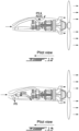
FIG. 16 is a perspective view of an unclaimed exemplary wing-mounted pusher turboprop gas turbine engine for the aircraft ofFig. 1 , with a nacelle thereof shown partially transparent; -
FIG. 17 , an unclaimed example, is a schematic cross-sectional view of an engine core of the pusher gas turbine engine ofFig. 16 taken on a plane normal to a longitudinal axis of the pusher gas turbine engine and illustrating mounts of a mounting structure for securing the engine core to a wing of the aircraft ofFig. 1 ; and -
FIG. 18 , an unclaimed example, s a schematic cross-sectional view of the engine core of the pusher gas turbine engine ofFig. 16 taken on the plane normal to the longitudinal axis of the pusher gas turbine engine and illustrating a mount of a mounting structure in accordance with another embodiment for securing the engine core to the wing of the aircraft ofFig. 1 . -
FIG. 1 illustrates anexemplary aircraft 10 to which one or moregas turbine engines 12 may be mounted. Thegas turbine engines 12 are turboprops, and are mounted to the aircraft in pusher configurations, whereby the engine is mounted with thepropeller 14 located behind the engine (relative to the direction oftravel 15 of the aircraft 10 - also referred to herein and depicted in the drawings as the "pilot view" direction). In the embodiment ofFig. 1 , the pusher turboprop gas turbine engines 12 (or simply "pusher engines") are mounted to thewings 17 of the aircraft. - The terms "upstream" and "downstream" as used herein, unless indicated otherwise, are understood to be relative to the direction of
travel 15 of the aircraft (i.e. the "pilot view" direction). Similarly, the terms "forward" and "rearward" as used herein are also understood to be relative to the direction oftravel 15 of the aircraft. - Each
pusher engine 12 as described herein will generally be referred to in the singular, however it is to be understood that two or more or each of such engines may be provided on theaircraft 10. - Each
pusher engine 12 defines a longitudinal axis LA (e.g., central axis). In various embodiments, longitudinal axis LA may correspond to an axis of rotation ofpropeller 14 and/or longitudinal axis LA may correspond to an axis of rotation of a low-pressure spool and/or a high-pressure spool of acore 13 of thegas turbine engine 12. Eachgas turbine engine 12 may be housed in anacelle 16, serving as an aerodynamically-shaped covering forgas turbine engine 12. - The
pusher engine 12 accordingly includes an engine core 13 (including compressor(s) 22,combustor 24 and turbine(s) 26) and areduction gearbox 38 which drives thepropeller 14, which is located rearward of thegas turbine engine 12, relative to a direction of travel of the aircraft, as is the case for pusher-style engines. - The pusher engines as described in further detail below are generally intended to be wing-mounted, in that the
nacelle 16 and theengine 12 are mounted to, and overtop of, awing 17 of theaircraft 10. However, as mentioned above, it is to be understood that the pusher turboprop engines and installations described herein may also be adapted for being mounted to the fuselage of the aircraft and/or to pylons mounted to the aircraft. - Referring to
Fig. 2 , thegas turbine engine 12 comprises anair intake 18 for channeling a flow of ambient air intogas turbine engine 12.Air intake 18 comprisesintake inlet 20 that is generally forward-facing and, in at least one particular embodiment, may be substantially aligned with the longitudinal axis LA of theengine 12. In typical pusher installations, the air intake is often offset radially outwardly (e.g. downwardly) relative to the longitudinal axis LA of engine. In at least some of the embodiments described herein, however, theintake inlet 20 of theair intake 18 is substantially axially aligned with thegas turbine engine 12, thereby allowing for a slimmer (e.g. smaller diameter)nacelle 16.Intake inlet 20 may be generally forward-facing, so that ambient air ingested into theair intake 18 is directed rearward within the envelope of the nacelle and to theengine air inlet 21 of theengine 12. - As best seen in
Fig. 3A , thepusher engine 12 may be of a type suitable for use in aircraft applications for subsonic flight generally comprising, in serial flow communication,air intake 18 through which ambient air is received, a compressor section 22 (which may be a multistage compressor) for pressurizing the air, acombustor 24 in which the compressed air is mixed with fuel and ignited for generating an annular stream of hot combustion gases, and turbine section 26 (which may be a multistage turbine) for extracting energy from the combustion gases. In various embodiments,gas turbine engine 12 may have a dual-spool configuration but it is understood thatgas turbine engine 12 may not be limited to such configuration. For example,gas turbine engine 12 may comprise high-pressure spool 28 including one or more stages ofmultistage compressor 22 and one or more high-pressure turbines 30 ofturbine section 26.Gas turbine engine 12 may also comprise low-pressure spool 32 including one or more stages ofmultistage compressor 22 and one or more low-pressure (i.e., power)turbines 34 ofturbine section 26. Low-pressure spool 32 may be mechanically coupled tooutput shaft 36 via areduction gearbox 38, to which thepropeller 14 may be coupled. - Referring still to
Fig. 3A , in one particular embodiment theair intake 18 of thepusher engine 12 includes a forward-facingintake inlet 20 receiving the ambient air, and aninlet duct 44 in fluid communication with theintake inlet 20 and extending downstream therefrom. More particularly, theair inlet duct 44 extends from theintake inlet 20 to theengine air inlet 21, such as to provide the main airflow into thecore 13 of theengine 12. Theair inlet duct 44 includes a first, or upstream,section 43 that extends immediately downstream of theintake inlet 20 and may be, in one particular embodiment, centrally located such that an intake axis IA defined by theintake inlet 20 is substantially concentric with the longitudinal axis LA of theengine 12. A second, or downstream,section 45 of theair inlet duct 44 terminates at theengine air inlet 21. As best seen inFig. 3B , in one particular embodiment, this seconddownstream section 45 of theair inlet duct 44 may be bifurcated into twoseparate ducts 45' and 45". In the embodiment ofFig. 3B , the twoseparate ducts 45' and 45" are bifurcated relative to a central vertical plane extending through the longitudinal engine axis LA. Accordingly, the outlets of each of theseducts 45' and 45" may thereby direct the inlet airflow into opposite sides of anannual quasi-scroll intake 49 that that feeds theengine air inlet 21. In the embodiment ofFig. 3B , therefore, thedownstream duct section 45 is bifurcated, thereby comprising the bifurcatedduct portions 45' and 45" which are split at the top-dead-center (TDC) and may thus be located at 11 and 1 o'clock, for example. Thebifurcated duct portions 45' and 45" of thedownstream duct 45 feed air to theengine air inlet 21 at two circumferential locations, thereby partially wrapping around the annular engine inlet and thus forming a "quasi-scroll" type air inlet duct configuration. This quasi-scroll inlet configuration may contribute to ensuring relatively low losses and enable some ram recovery of the air entering theengine core 13. By integrating the front-facingair inlet 20 andinlet duct 44, and such as quasi-scroll type inlet ducting to theengine air inlet 21, overall engine performance (e.g. specific fuel consumption (SPC)) may accordingly be improved. - As seen in both
Fig. 3A and 3B , an additional air duct 47 (which may also be referred to herein as a "second air outlet duct" or simply as an "oil cooler duct"), directs a portion of the incoming cool air into an air-cooled-oil-cooler (ACOC) 50. In the depicted embodiment, theACOC air duct 47 is fluidly connected to theair inlet duct 44 at a point thereon between the first, upstream,section 43, and the second, downstream,section 45. This connection point may also be located over thewing 17 and downstream (and axially aft) of an inertial particle separator duct 42, as will be described in further detail below. More particularly, between theintake inlet 20 and theengine air inlet 21, a portion of the airflow within the mainair inlet duct 44 is diverted away into theACOC inlet duct 47. Theair intake 18 therefore includes two separate outlet ducts, namely the main air inlet flow within thedownstream duct section 45 of theair inlet duct 44, which directs a portion of the inlet airflow into thecore 13 of theengine 12, and theACOC air duct 47, which directs another portion of the incoming air into an air-cooled-oil-cooler (ACOC) 50. The portion of the inlet airflow directed to the engine core may be a major or majority portion of the incoming airflow, and the portion of the airflow directed into theACOC 50 may be a small portion of the total incoming airflow. As such, theair duct 47 directs a portion of the air flowing through theinlet duct 44 to theACOC 50, and a remaining portion of the incoming air is directed through thedownstream duct portion 45 to the enginecore air inlet 21. - The
ACOC 50 may be located in-line within theACOC air duct 47. TheACOC 50 is used to cool engine oil, by transferring the heat from the engine oil to the cooler air flowing through thesecond outlet duct 47. After flowing through theACOC 50, the air (by then heated by the ACOC) can flow out of thesecond outlet duct 47 for ejection - either externally to atmosphere or within the nacelle 16 - or re-use for other purposes (e.g. ant-icing over nacelle or engine components. - Accordingly, as described above and shown in
Fig. 3A , air inters theair intake 18 through thecommon inlet duct 44, and at a point located downstream of theintake inlet 20 splits into the main enginedownstream duct portion 45 and the ACOCair inlet duct 47, in order to feed incoming air into theengine core 13 and to theACOC 50, respectively. As shown, in this embodiment, thesecond outlet duct 47 and theACOC 50 that is fed by it are both located axially forward of theengine core 13 of theengine 12, but may be substantially aligned therewith (relative to the axis LA) such as to produce an overall relative "long and thin" envelope for thenacelle 16, which therefore has a relatively long forward "snout". As seen inFig. 3A , theACOC 50 and theair duct 47 feeding it may be axially located in line (or overtop of) thewings 17 of the aircraft, with the majority of theengine 12 and/or the center of the mass of theengine 12 being located axially after of thewings 17. - As shown in
Figs. 3A and Fig. 3B , the first, most upstream,section 43 of theinlet duct 44 of theair intake 18 is centrally located within thenacelle 16 relative to the engine centerline LA. As such, intake axis IA of thefirst section 43 of theinlet duct 44 may be substantially coaxial with the main engine axis LA, as seen inFigs. 3A and 3B . Thedownstream duct section 45, and thus thebifurcated duct portions 45' and 45", may however be radially offset from theinlet duct 44 and thus the intake axis IA, extending up and radially outward (over theaccessory gear box 11 which is also axially aligned with the engine axis LA in order to maintain a slim radial envelope) before redirecting radially inward to theengine air inlet 21. - Given that the
turboprop engine 12 is a pusher engine with thepropeller 14 located aft of theengine core 13 and having a front-facingair inlet 20, the possible effect of foreign object damage (FOD) caused by particles (e.g. ice, debris, etc.) in the incoming air should be considered. Accordingly, as seen inFig. 3A , theair intake 18 also optionally includes an inertial particle separator (or "IPS") 60. TheIPS 60 is located upstream, and axially forward, of theengine air inlet 21, so as to prevent ingestion of ice, other particles and/or other FOD-causing objects into the engine. The terms "particles" or simply "FOD" may be used herein to describe generally all of such FOD particles/objects, even though it will be understood that in some cases the FOD-causing objects in question may be significantly larger than an ice or other particle per se - such as a bird or other airborne object for example that could be unintentionally ingested into the engine's air intake. In the embodiment ofFig. 3A , theIPS 60 is also located upstream, and axially forward, of theACOC 50. More particularly, theIPS 60 includes anIPS duct 64 that is fluidly connected with theupstream section 43 of theair inlet duct 44, and a FOD particle separator that is capable of separating FOD particles from the incoming airflow and re-directing them into theIPS duct 64. Accordingly, such undesirable FOD particles prevented from flowing unhindered downstream, through theair inlet duct 44 and thus into the air inlet of theengine 12. - In the embodiment of
Fig. 3A , theIPS 60 includes a one or more FOD-deflectors, or FOD-diverters, that extend at least partially into the air inlet duct and act to redirect any FOD into theIPS duct 64. In one particular embodiment, the FOD-deflectors comprise one or more FOD-diverting plates 62 (or simply "plates" hereinbelow) which project into theupstream section 43 of theair inlet duct 44, at a location upstream of theIPS duct 64. TheFOD diverting plates 62, which in the depicted embodiment include three plates however fewer or more plates may alternately be used, may be either stationary or movable such as to be adjusted into a desired position relative to one another and relative to the incoming airflow through theinlet duct 44. In one particularly embodiment, wherein at least oneplate 62 is movable, the plate is displaceable between a deployed position and a retracted position. In the deployed position, the plate will protrude into the air inlet duct to redirect FOD. In the retracted position, the plate is substantially withdrawn from the airflow through the air inlet duct and will therefor generate less flow restriction. It is to be understood that in some embodiments, the moveable plate may be positioned not just at these two end points of its travel, i.e. at the fully retracted and fully deployed position, but may also be positioned a number of possible intermediate positions between these two extremes. In the depicted embodiment, each of the threeplates 62 may be independent movable, and each may comprise either a two-state active control (e.g. being either deployed or retracted, as needed) or a fully variable active control whereby any desired angular position of each of the plates can be selected as required. - Regardless of whether they are fixed or movable, the
plates 62 are positioned such as to divert any potential FOD-causing particles that might enter theinlet duct 44 into theIPS duct 64, for subsequent discharge overboard. Unwanted FOD-causing particles are therefore diverted into theIPS duct 64, and prevented from flowing further downstream and thus from being ingested into theengine air inlet 21 or theACOC 50. In one particular embodiment, a plurality ofplates 62 are provided and extend into theair inlet duct 44, with at least a first one of the plurality of plates extending away from an inner wall of the air inlet duct in a downstream direction, and at least a second one of the plurality of plates extending from an inner wall of the air inlet duct in an upstream direction. In some embodiments, the plate which is more downstream within the air inlet duct will be the one which extends in the upstream direction away from the wall of the air inlet duct. These first and second ones of the plates may be mounted to the same inner wall of the air inlet duct, or may be located on opposite sides from each other with the duct. - The
IPS duct 64 may therefore be integrated with theinlet duct 44, and it projects away therefrom downward and radially away from the inlet axis IA. As can be appreciated fromFig. 3A , theIPS duct 64 in this embodiment is separate and distinct from, and located upstream of, thesecond outlet duct 47 feeding air to theACOC 50. TheIPS duct 64 may thus be axially located forward of thewing 17 of the aircraft, such as to expel any unwanted FOD particles outboard and away from the aerodynamic surfaces of thewings 17. Thesecond outlet duct 44 and theACOC 50, in this embodiment, are axially positioned over thewing 17, with theengine core 13 of thegas turbine engine 12 being located substantially rearward of thewing 17. - Several other embodiments of the present air intakes will now be described. Unless otherwise indicated, the features of each of the following engines and their respective air inlets will be similar to those of the
pusher engine 12 and theair inlet 118 as described above. Only the differences will be described in more detail below, for the avoidance of repetition. - Referring now to the embodiment of
Fig. 4A-4B , thepusher engine 112 includes anair intake 118 in which the IPS duct and the ACOC duct are integrated into asingle air duct 164, which is connected to the mainair inlet duct 144 such as to divert a portion of the flow therethrough. More particularly, theIPS duct 164 of the present air intake configuration includes theACOC 50 therein, thereby avoiding the need for an additional air duct exclusively for the ACOC. The combined IPS andACOC duct 164 is located forward of thewing 17 of the aircraft. - Additionally, unlike the
air inlet duct 44 described above, theair inlet duct 144 is not bifurcated at TDC, as can be best seen inFig. 4B . Thedownstream section 145 of theair inlet duct 144 therefore connects to the engine air inlet quasi-scroll 49 at a single location, for example at TDC. The engine air inlet is therefore a single inlet, quasi-scroll configuration. - Referring now to the embodiment of
Fig. 5A-5B , thepusher engine 212 includes anair intake 218 which is formed such that the overall axial length of thenacelle 216 required is shorter than that of theengines engines air intake 118, theair intake 218 includes an integrated IPS andACOC duct 264 that includes theACOC 50. In this embodiment, however, theIPS 260 employs one or more fixed elements projecting into theupstream portion 243 of the mainair inlet duct 244. For example, the one or more fixed elements may include a fixed icing screen, which will capture ice particles within the incoming airflow. The fixedicing screen 262 may be part of a two state, passive system, rather than the active systems of themovable plates 62 described above. - Inlet screens as described herein may comprise a metallic screen acts in operation to substantially prevent foreign objects (e.g., pieces of ice) larger than a certain size from exiting intake outlet. The screen(s) may also serve as a surface on which ice is permitted to accrete, thereby preventing or reducing the likelihood of ice accreting further downstream into gas turbine engine.
- Referring now to the embodiment of
Fig. 6 , thepusher engine 312 includes anair intake 318 which is even further simplified, in that it includes no fixed icing screen or other projecting plates as part of an IPS. Much as per the air intakes 118 and 218, theair intake 318 similarly includes an integrated IPS andACOC duct 364 that includes theACOC 50. - Referring now to the embodiment of
Fig. 7 , thepusher engine 412 includes anair intake 418 which is similar to that ofair intake 18 described above, in that it includes aseparate IPS duct 464 andACOC duct 447. In this embodiment, however, no IPS plates or other icing screens (fixed or otherwise) are provided as part of an IPS system. - Referring now to the unclaimed example of
Fig. 8 , thepusher engine 512 includes anair intake 518 that includes both anIPS duct 564 and anACOC duct 547. However, in this unclaimed example, theACOC duct 547 is not integrated with or connected directly to the mainair inlet duct 544 feeding the air to the engine core. Rather, theACOC duct 547 containing theACOC 50 is mounted separately within thenacelle 516, over thewing 17, and receives incoming airflow from air flowing through thenacelle 16. In other words, the air directed through theACOC duct 547 is not air which is diverted off from the main air inlet flow to the engine core. All of the air entering the front-facingair inlet 20 is therefore directed through theair inlet duct 544 to theengine air inlet 21. -
Fig. 9 depicts another unclaimed example, similar to that ofFig. 8 , except wherein theACOC duct 647 is mounted below thewing 17, instead of above it. As such, the air directed through theACOC duct 647 can be drawn from outside thenacelle 616 throughinlet 650. However, in an alternate unclaimed example, theinlet 650 of theACOC duct 647 may still be located such as to dawn air from outside thenacelle 616, however with theACOC duct 647 located elsewhere within the nacelle. -
Figs. 10-12 depict alternate unclaimed examples, wherein the ACOC duct is disposed in other locations within the nacelle, generally aft of the wing of the aircraft. The ACOC duct may similarly be separate from (Figs. 10 and 11 ) or integrated with (Fig. 12 ) the IPS duct. -
Fig. 13 depicts an alternate unclaimed example, similar to that ofFig. 8 , except having an air inlet plenum (or "dump box") at the engine air inlet, rather than the quasi-scroll air inlet configuration. - Referring now to the unclaimed example of
Fig. 14 , thepusher engine 612 includes anair intake 618 that includes anIPS duct 664 that and anACOC duct 647. TheIPS duct 64 is fluidly connected with theupstream section 643 of theair inlet duct 644, and a FOD particle separator that is capable of separating FOD particles from the incoming airflow and re-directing them into theIPS duct 664, for ejection overboard at 690. Accordingly, such undesirable FOD particles are prevented from flowing unhindered downstream, through theair inlet duct 644 and thus into theair inlet 21 of theengine 612. - In this unclaimed example, the
air intake 620 and theupstream section 643 of theair intake 618 is located near the upper portion of the nacelle, and is not axially aligned with the engine. More particularly, theair intake 618 of theupstream section 643 of theair inlet duct 618 defines an intake axis IA that is radially offset (parallel to and spaced apart) from the from the main engine axis LA, as can be seen inFig. 14 . - As can also be seen in
Fig. 14 , in this unclaimed example, theACOC duct 647 is split apart from theIPS duct 664 and the rest of theair inlet duct 644 of theair intake 618. TheACOC duct 647 is located, in this unclaimed example, below the engine core, and draws air directly from outside the engine and/or outside the nacelle, for feeding through the ACOC in theACOC duct 647. Accordingly, the airflow used to cool the ACOC, which flows through theACOC duct 647, is independent from the airflow through theair intake 618, which feeds the engine. -
Fig. 15 depicts an alternate unclaimed example, similar to that ofFig. 14 , having anACOC duct 747 that is split apart from theIPS duct 764 and the rest of theair inlet duct 744 of theair intake 718. In this unclaimed example, however, theACOC duct 747 is located above the engine core, rather than below, and is axially located rearward of theIPS duct 764 and theair intake 718. Nevertheless, the airflow feeds to theair intake 718 and theACOC duct 747 are separate, and each draws ambient air in from different external inlets in the nacelle. - In various embodiments, the air intake may channel the flow of ambient air (represented by the arrow F in the figures) toward engine inlet of gas turbine engine. The engine inlet may have a substantially annular shape and may be disposed upstream of
compressor 22 of the engine. For the purpose of description and reference with the figures, the air intake may define an intake axis IA, which in certain embodiments may be substantially coaxial with annular engine inlet and/or substantially coaxial with longitudinal axis LA (e.g., center line) of gas turbine engine when air intake is installed on gas turbine engine. The engine inlet may comprise an annular opening into which the flow of air discharged substantially axially rearwardly from intake outlet. In some embodiments, the annular engine inlet may be coaxial with longitudinal axis LA of gas turbine engine. In some embodiments, the longitudinal axis LA of gas turbine engine may correspond to the axis or rotation of high-pressure spool 28 and of low-pressure spool 32 as shown inFIG. 3A . Accordingly, in embodiments where an axis of rotation ofpropeller 14 is radially offset from an axis of rotation of high-pressure spool 28 and low-pressure spool 32, the longitudinal axis LA may not necessarily correspond to the axis of rotation ofpropeller 14. In various embodiments, the intake axis IA may be either substantially coaxial the longitudinal axis LA, or may be offset therefrom (e.g. spaced apart therefrom in a radial or transverse direction from the longitudinal axis). - The
annual quasi-scroll intake 49 that that feeds theengine air inlet 21, as described above with reference toFig. 3A , may be in fluid communication withintake duct 44 and receive the flow of air F fromintake duct 44. A scroll portion of thequasi-scroll intake 49 may channel the flow of air F toward engine inlet via the intake outlet. The scroll portion may define one or more converging quasi scroll-shaped passages formed such as to cause acceleration and redirection of the flow of air F toward engine inlet with relatively low energy losses and pressure distortion. - During operation, the present air intakes may be installed on gas turbine engine and used to channel a flow of air to engine inlet with relatively low energy losses and flow distortion (e.g., swirl and pressure distortions). Air intake may define a generally streamlined flow path between intake inlet and the intake outlet. For example, in some embodiments, air intake may not comprise a plenum (i.e., dump box) often found in traditional air intakes and which may cause significant energy losses. In various embodiments, improvements of flow characteristics of the flow or air F may improve engine performance in comparison with some other traditional air intakes.
- In various embodiments, the air intakes as described herein may be fabricated according to known or other manufacturing methods using suitable sheet metal or polymeric material. In some embodiments, air intake or part(s) thereof may be cast using a suitable metallic material or molded from a suitable polymeric material. In some embodiments, air intake may comprise a plurality of components (e.g., pieces of sheet metal) pieced (e.g., welded) together to form air intake.
- Referring now to
Fig. 16 , in the unclaimed example shown, anaccessory gearbox 11 is in driving engagement with the low-pressure spool 32 (Fig. 3A ) of theengine 12. The accessory gearbox (AGB) 11 defines at least one, three in the unclaimed example shown,outputs 11a for accessories (not shown) to be drivingly engaged to the low-pressure spool 32 via theaccessory gearbox 11. As shown, theoutputs 11a face a direction having a radial component relative to the longitudinal axis LA of theengine core 13. The accessories connected to theoutputs 11a are herein located radially between thenacelle 16 and theoutputs 11a. In other words, the disclosedpusher engine 12 allows the accessories to be located radially outwardly of thegearbox 11 and radially inwardly of thenacelle 16 relative to the axis LA. Consequently, anaccess door 16a of thenacelle 16 may allow easy access via anopening 16b defined through thenacelle 16 to replace, repair, and perform maintenance of the accessories without having to dismantle thepusher engine 12. - Still referring to
Fig. 16 , an unclaimed example, a mounting structure M is used to secure theengine core 13 to thewing 17. The mounting structure includes aframe 100. Theframe 100 is herein secured to both of fore andaft spars wing 17. The fore andaft spars wing 17, from a root of thewing 17 to a tip thereof. Thefore spar 17a is located proximate a leading edge of thewing 17 whereas theaft spar 17b is located proximate a trailing edge of thewing 17. - In the unclaimed example shown, the
frame 100 includes a plurality ofmembers 100a that are secured to one another. Themembers 100a are assembled to define an engine-receiving space S sized to contain theengine core 13 and theAGB 11. Themembers 100a may be tubular members. - However, having a side mounted
accessory gearbox 11, with side mounted accessories, might complicate installation of theengine core 13 andAGB 11 on thewing 17 as a radial dimension of theengine core 13 with theAGB 11 might be too big to allow thepusher engine 12 to be inserted in the engine-receiving space S by moving saidengine 12 along its axis LA. Some of theframe members 100a may prevent penetration of theengine core 13 andAGB 11 into the engine-receiving space S if the engine andAGB - Referring now to
Figs. 16 and 17 , unclaimed examples, theengine core 13 is installed by moving said engine core in a vertical direction VD relative to a ground G. The vertical direction may correspond to a radial direction relative to the longitudinal axis LA of theengine core 13. In the unclaimed example shown, theengine core 13 is inserted in the desired position by decreasing an elevation of theengine core 13 relative to the ground G. In other words, theengine core 13 is lowered into the desired position into the engine-receiving space S by bringing theengine core 13 closer to the ground G. - In the depicted unclaimed example, the
frame 100 has anupper frame portion 100b and alower frame portion 100c both including some of thetubular members 100a. As shown more clearly onFig. 16 , the mounting structure M further includes amount ring 102 for connecting theengine core 13 to theframe 100. Each of the upper andlower frame portions U-shaped mounts mount ring 102. The U-shaped mounts are also referred to as horseshoe-shaped mount. Both of theU-shaped mounts engine core 13 relative to the longitudinal axis LA. Thelower frame portion 100c and the lowerU-shaped mount 102b are secured to thewing 17 via the fore andaft spars upper frame portion 100b and the upperU-shaped mount 102a are secured to theengine core 13 prior to moving theengine core 13 in the desired position. The lowerU-shaped mount 102b defines an opening O oriented away from the ground G when the aircraft is on the ground G. The upper andlower frame portions U-shaped mounts engine core 13 andAGB 11 are in the desired position, within the engine-receiving space S. - The
engine core 13 includes a plurality ofpads 13a that are circumferentially distributed around the longitudinal axis LA. Thepads 13a are herein secured to agas generator case 13b of theengine core 13. Thegas generator case 13b is a case that surrounds thecombustor 24 of theengine core 13. It will be appreciated that thepads 13a may be secured to the compressor case and/or to the turbine-exhaust case. Theengine core 13 may be secured to theU-shaped mounts frame 100 via any suitable case of theengine core 13. Elastomeric material may be located between the upper and lowerU-shaped mounts pads 13a for dampening vibrations occurring with operation of thegas turbine engine 12. - Referring to
Figs. 16 and 17 , unclaimed examples, for mounting thegas turbine engine 12 to thewing 17 of theaircraft 10, the mounting structure S is secured to thewing 17 of theaircraft 10; theengine core 13 is inserted within the engine-receiving space S by changing the elevation of theengine core 13 relative to the ground G until theengine core 13 is at least partially enclosed by the lowerU-shaped mount 102b; and theengine core 13 is secured to the lowerU-shaped mount 102b. - In the present case, the
lower frame portion 100c is secured to thewing 17; the lowerU-shaped mount 102b is secured to thelower frame portion 100c; theupper frame portion 100b and the upperU-shaped mount 102a are secured to theengine core 13; and theengine core 13 is inserted into the engine-receiving space S by moving theengine core 13 in the vertical direction VD toward the ground G until theengine core 13 is received within the lowerU-shaped mount 102b via its opening O facing away from the ground G. The upper and lowerU-shaped mounts lower frame portions 100c, 100d, may be secured to one another. - Referring to now to Fig. 19, in an alternate unclaimed example, the mounting structure includes only one
U-shaped mount 104 defining an opening O' facing toward the ground G. Theengine core 13 is receivable within the engine-receiving space S in an upward direction away from the ground G. - As shown in Fig. 19, an unclaimed example, for mounting the
engine core 13 to thewing 17, theengine core 13 is elevated away from the ground G until theengine core 13 is at least partially enclosed by theU-shaped mount 104. At which point, theengine core 13 is secured to theU-shaped mount 104 via thepads 13a secured to thegas generator case 13b. - In the unclaimed example shown, the
engine core 13 may be inserted in the engine-receiving space S without having to mount any frame portion thereto. In other words, a frame may include only a single portion that is secured to thewing 17 via thespars mount 104 is secured to the frame before installing theengine core 13. After theengine core 13 is inserted in the engine-receiving space S, theengine core 13 is secured to theU-shaped mount 104 via thepads 13a. - Referring to
Figs. 16-18 , unclaimed examples, after theengine core 13 is at the desired position, theair inlet 18 and other components such as thenacelle 16 may be installed. In the unclaimed example shown, the twoseparate ducts 45', 45" (Fig. 3B ) are connected to the annular quasi-scroll 49 (Fig. 4A ) at a connection point C such that the quasi-scroll 49 may be secured to theengine core 13 separately from theducts 45', 45". In the present case, after theengine core 13 is installed in the desired position, the quasi-scroll 49 is installed and then theducts 45', 45" are installed and connected to the quasi-scroll 49 at the connection point C. - The above description is meant to be exemplary only, and one skilled in the relevant arts will recognize that changes may be made to the embodiments described without departing from the scope of the appended claims.
Claims (9)
- A turboprop gas turbine engine adapted to be mounted to an aircraft, the turboprop gas turbine engine comprising:a nacelle (16);a propeller (14);an air-cooled-oil-cooler (ACOC) (50);an engine core (13) and a gearbox (38) driving the propeller (14), the engine core (13) and the gearbox (38) being enclosed within the nacelle (16), the propeller (14) configured to be located rearward of the gearbox (38) and the engine core (13) relative to a direction of travel of the aircraft, the turboprop gas turbine engine being a pusher engine (12), the engine core (13) defining a central longitudinal axis (LA); andan air intake (18) disposed within the nacelle (16) and formed to direct ambient air into the engine core (13) of the turboprop gas turbine engine, the air intake (18) including an air inlet duct (44) having a forward-facing intake inlet (20) receiving the ambient air, the air inlet duct (44) including an upstream section (43) and a downstream section (45), the upstream section (43) of the air inlet duct (44) in fluid communication with the intake inlet (20) and extending downstream from the intake inlet (20), the downstream section (45) of the air inlet duct (44) fluidly connected to and directing air from the upstream section (43) into an engine air inlet (21) of the engine core (13), whereinthe upstream section (43) of the air inlet duct (44) is centrally located within the nacelle (16) relative to the central longitudinal axis (LA), and the intake inlet (20) of the air intake (18) extends along an intake axis (IA) that is either substantially coaxial with the central longitudinal axis (LA) or radially spaced apart therefrom, anda second air outlet duct (47) is located within the nacelle (16), the second air outlet duct (47) is connected to the air inlet duct (44) at a location between the upstream section (43) and the downstream section (45) thereof, the location being between the intake inlet (20) and the engine air inlet (21), the second air outlet duct (47) directing air from the upstream section (43) of the air inlet duct (44) into the ACOC (50),characterised in that the ACOC (50) and the second air outlet duct (47) are located axially forward of the engine core (13).
- The turboprop gas turbine engine as defined in any one of the preceding claims, further comprising an inertial particle separator (IPS) (60) located downstream of the intake inlet (20) and upstream of the engine air inlet (21), the inertial particle separator (60) operable to redirect foreign object damage (FOD) particles in the air flowing through the air inlet duct (44) into an IPS duct (64) connected in fluid flow communication with the air inlet duct (44).
- The turboprop gas turbine engine as defined in claim 2, wherein the ACOC (50) and the IPS (60) are integrated into a common duct configured to be located axially forward of the engine core (13) and of a wing (17) of an aircraft (10).
- The turboprop gas turbine engine as defined in claim 2, wherein the IPS duct (64) is located axially forward of the engine core (13), an outlet of the IPS duct (64) disposed to expel the FOD particles out of the nacelle (16) and away from a wing (17) of an aircraft (10).
- The turboprop gas turbine engine as defined in any one of claims 2 to 4, wherein the IPS (60) includes one or more FOD-deflectors (62) that extend at least partially into the air inlet duct (44), the one or more FOD-deflectors (62) redirect the FOD particles into the IPS duct (64) which is connected to the air inlet duct (44) at or downstream from the one or more FOD-deflectors (62).
- The turboprop gas turbine engine as defined in claim 5, wherein the one or more FOD-deflectors (62) include a plate (62) extending into the air inlet duct (44) at an angle relative to an outer wall of the air inlet duct (44), and optionally wherein the plate (62) is movable between a deployed position and a retracted position, in the deployed position the plate (62) protruding into the air inlet duct (44) to redirect FOD particles, and in the retracted position the plate (62) being substantially withdrawn from the airflow through the air inlet duct (44) and generating less flow restriction.
- The turboprop gas turbine engine as defined in claim 6, wherein the plate (62) is actively controlled and positionable in any one or more of the deployed position, the retracted potion, and any angular position therebetween.
- The turboprop gas turbine engine as defined in claim 6 or 7, further comprising a plurality of plates (62) extending into the air inlet duct, at least a first one of the plurality of plates (62) extending away from a wall of the air inlet duct (44) in a downstream direction, and at least a second one of the plurality of plates (62) extending from a wall of the air inlet duct (44) in an upstream direction.
- The turboprop gas turbine engine as defined in claim 8, wherein the second one of the plurality of plates (62) is located more downstream within the air inlet duct (44) relative to the first one of the plurality of plates (62) and/or wherein the first one of the plurality of plates (62) and the second one of the plurality of plates (62) are disposed on opposite walls of the air inlet duct (44).
Applications Claiming Priority (2)
| Application Number | Priority Date | Filing Date | Title |
|---|---|---|---|
| US201962888159P | 2019-08-16 | 2019-08-16 | |
| US201962890127P | 2019-08-22 | 2019-08-22 |
Publications (3)
| Publication Number | Publication Date |
|---|---|
| EP3778402A2 EP3778402A2 (en) | 2021-02-17 |
| EP3778402A3 EP3778402A3 (en) | 2021-06-09 |
| EP3778402B1 true EP3778402B1 (en) | 2024-09-25 |
Family
ID=72088030
Family Applications (1)
| Application Number | Title | Priority Date | Filing Date |
|---|---|---|---|
| EP20191228.4A Active EP3778402B1 (en) | 2019-08-16 | 2020-08-14 | Pusher turboprop powerplant installation |
Country Status (2)
| Country | Link |
|---|---|
| US (1) | US11635024B2 (en) |
| EP (1) | EP3778402B1 (en) |
Families Citing this family (3)
| Publication number | Priority date | Publication date | Assignee | Title |
|---|---|---|---|---|
| CN113636089B (en) * | 2021-08-25 | 2023-07-21 | 成都飞机工业(集团)有限责任公司 | Slender double-engine air inlet channel structure and assembly method |
| US11964223B1 (en) * | 2022-10-15 | 2024-04-23 | Beta Air, Llc | Methods and apparatus for an inertial separation of air in an electric aircraft |
| US12228075B2 (en) | 2022-12-09 | 2025-02-18 | General Electric Company | Integral engine inlet frame air-cooled oil cooling apparatus |
Citations (1)
| Publication number | Priority date | Publication date | Assignee | Title |
|---|---|---|---|---|
| EP3211199B1 (en) * | 2016-02-24 | 2020-04-01 | Pratt & Whitney Canada Corp. | Air intake for turboprop engine |
Family Cites Families (19)
| Publication number | Priority date | Publication date | Assignee | Title |
|---|---|---|---|---|
| US2625009A (en) * | 1948-07-15 | 1953-01-13 | Curtiss Wright Corp | Vehicle engine cooling system utilizing air ejector pump to induce flow of additional cooling air |
| US4930725A (en) | 1988-12-16 | 1990-06-05 | Allied-Signal Inc. | Pusher propeller installation for turboprop engines |
| DE19524733A1 (en) | 1995-07-07 | 1997-01-09 | Bmw Rolls Royce Gmbh | Aircraft gas turbine engine with a liquid-air heat exchanger |
| DE19524731A1 (en) | 1995-07-07 | 1997-01-09 | Bmw Rolls Royce Gmbh | Turboprop engine with an air-oil cooler |
| FR2788308A1 (en) | 1999-01-07 | 2000-07-13 | Snecma | COOLING DEVICE FOR A TURBOMACHINE SPEED REDUCER |
| FR2862611B1 (en) | 2003-11-25 | 2007-03-09 | Airbus France | DEVICE FOR ATTACHING AN ENGINE UNDER AN AIRCRAFT SAIL |
| FR2862944B1 (en) | 2003-12-01 | 2006-02-24 | Airbus France | DEVICE FOR ATTACHING A TURBOPROPULSER UNDER AN AIRCRAFT VESSEL |
| FR2916736B1 (en) | 2007-06-04 | 2009-09-04 | Airbus France Sa | APPARATUS FOR HANDLING AN AIRCRAFT TURBOPROPULSER COMPRISING HYDRAULIC FASTENING MEANS. |
| DE102009010524A1 (en) | 2009-02-25 | 2010-09-02 | Rolls-Royce Deutschland Ltd & Co Kg | Turboprop drive with pressure propeller |
| FR2955616B1 (en) | 2010-01-26 | 2012-07-20 | Airbus Operations Sas | COOLING DEVICE FOR AN AIRCRAFT PROPELLER |
| GB201017303D0 (en) | 2010-10-14 | 2010-11-24 | Rolls Royce Plc | Support structure |
| FR2976914B1 (en) | 2011-06-23 | 2014-12-26 | Snecma | STRUCTURE FOR ATTACHING A TURBOMACHINE |
| FR2994942B1 (en) | 2012-09-06 | 2015-08-07 | Airbus Operations Sas | LATERAL PROPULSIVE ASSEMBLY FOR AIRCRAFT COMPRISING A SUPPORT ARM OF A TURBOMOTEUR. |
| EP2932068B1 (en) | 2012-12-13 | 2017-11-15 | United Technologies Corporation | Gas turbine engine with cooling scheme for drive gear system and pitch control |
| EP3071481B1 (en) | 2013-11-18 | 2020-01-08 | LORD Corporation | Turboprop engine attachment systems and methods |
| US9238511B2 (en) | 2014-03-04 | 2016-01-19 | Mra Systems, Inc. | Engine pylon structure |
| US10054050B2 (en) | 2014-08-19 | 2018-08-21 | Pratt & Whitney Canada Corp. | Low noise aeroengine inlet system |
| FR3050722B1 (en) | 2016-04-28 | 2021-07-02 | Snecma | PROPULSION KIT FOR FILTERED CRADLE AIRCRAFT |
| FR3059298B1 (en) | 2016-11-29 | 2019-05-17 | Airbus Operations | AIRCRAFT ASSEMBLY COMPRISING A "OPEN ROTOR PULLER" TYPE ENGINE AND MEANS FOR HINGING IT WITH THE RIGID STRUCTURE OF A COUPLING MAT |
-
2020
- 2020-08-12 US US16/991,224 patent/US11635024B2/en active Active
- 2020-08-14 EP EP20191228.4A patent/EP3778402B1/en active Active
Patent Citations (1)
| Publication number | Priority date | Publication date | Assignee | Title |
|---|---|---|---|---|
| EP3211199B1 (en) * | 2016-02-24 | 2020-04-01 | Pratt & Whitney Canada Corp. | Air intake for turboprop engine |
Also Published As
| Publication number | Publication date |
|---|---|
| US11635024B2 (en) | 2023-04-25 |
| US20210047964A1 (en) | 2021-02-18 |
| EP3778402A2 (en) | 2021-02-17 |
| EP3778402A3 (en) | 2021-06-09 |
Similar Documents
| Publication | Publication Date | Title |
|---|---|---|
| EP3211204B1 (en) | Air intake with scroll portion and strutted portion for gas turbine engine | |
| US7861513B2 (en) | Aeroengine ventilation system | |
| CA2806567C (en) | Gas turbine engine with ejector | |
| US8256709B2 (en) | Aircraft with tail propeller-engine layout | |
| US9845159B2 (en) | Conjoined reverse core flow engine arrangement | |
| EP3211199B1 (en) | Air intake for turboprop engine | |
| US9169779B2 (en) | Systems and methods for altering inlet airflow of gas turbine engines | |
| EP2903894B1 (en) | Bifurcated inlet scoop for gas turbine engine | |
| EP2346736B1 (en) | Integrated inlet design | |
| US10829232B2 (en) | Aircraft comprising a propulsion assembly including a fan on the rear of the fuselage | |
| EP3778402B1 (en) | Pusher turboprop powerplant installation | |
| EP0255796A2 (en) | Gas turbine outlet arrangement | |
| EP2963276B1 (en) | Compact nacelle with contoured fan nozzle | |
| US20130230386A1 (en) | Diffuser Seal for Geared Turbofan or Turboprop Engines | |
| US12416262B2 (en) | Reverse flow gas turbine engine having electric machine | |
| JP7329900B2 (en) | Aero engine trailing edge core compartment exhaust | |
| US10974813B2 (en) | Engine nacelle for an aircraft | |
| US20120011826A1 (en) | Turbojet engine with an element of the nacelle attached to the intermediate casing | |
| EP4571074A1 (en) | Nacelle for turbo-propeller engines | |
| CA2783790A1 (en) | Gas turbine engine with ejector |
Legal Events
| Date | Code | Title | Description |
|---|---|---|---|
| PUAI | Public reference made under article 153(3) epc to a published international application that has entered the european phase |
Free format text: ORIGINAL CODE: 0009012 |
|
| STAA | Information on the status of an ep patent application or granted ep patent |
Free format text: STATUS: THE APPLICATION HAS BEEN PUBLISHED |
|
| AK | Designated contracting states |
Kind code of ref document: A2 Designated state(s): AL AT BE BG CH CY CZ DE DK EE ES FI FR GB GR HR HU IE IS IT LI LT LU LV MC MK MT NL NO PL PT RO RS SE SI SK SM TR |
|
| AX | Request for extension of the european patent |
Extension state: BA ME |
|
| PUAL | Search report despatched |
Free format text: ORIGINAL CODE: 0009013 |
|
| AK | Designated contracting states |
Kind code of ref document: A3 Designated state(s): AL AT BE BG CH CY CZ DE DK EE ES FI FR GB GR HR HU IE IS IT LI LT LU LV MC MK MT NL NO PL PT RO RS SE SI SK SM TR |
|
| RIC1 | Information provided on ipc code assigned before grant |
Ipc: B64D 27/12 20060101AFI20210503BHEP Ipc: B64D 27/14 20060101ALI20210503BHEP Ipc: F02C 6/20 20060101ALI20210503BHEP Ipc: F02C 7/12 20060101ALI20210503BHEP Ipc: B64D 33/02 20060101ALI20210503BHEP Ipc: B64D 27/26 20060101ALI20210503BHEP Ipc: B64F 5/10 20170101ALI20210503BHEP |
|
| STAA | Information on the status of an ep patent application or granted ep patent |
Free format text: STATUS: REQUEST FOR EXAMINATION WAS MADE |
|
| 17P | Request for examination filed |
Effective date: 20211209 |
|
| RBV | Designated contracting states (corrected) |
Designated state(s): AL AT BE BG CH CY CZ DE DK EE ES FI FR GB GR HR HU IE IS IT LI LT LU LV MC MK MT NL NO PL PT RO RS SE SI SK SM TR |
|
| STAA | Information on the status of an ep patent application or granted ep patent |
Free format text: STATUS: EXAMINATION IS IN PROGRESS |
|
| 17Q | First examination report despatched |
Effective date: 20230207 |
|
| REG | Reference to a national code |
Ref country code: DE Ref legal event code: R079 Free format text: PREVIOUS MAIN CLASS: B64D0027120000 Ref country code: DE Ref legal event code: R079 Ref document number: 602020038213 Country of ref document: DE Free format text: PREVIOUS MAIN CLASS: B64D0027120000 Ipc: B64D0027100000 |
|
| GRAP | Despatch of communication of intention to grant a patent |
Free format text: ORIGINAL CODE: EPIDOSNIGR1 |
|
| STAA | Information on the status of an ep patent application or granted ep patent |
Free format text: STATUS: GRANT OF PATENT IS INTENDED |
|
| RIC1 | Information provided on ipc code assigned before grant |
Ipc: B64D 27/10 20060101AFI20240402BHEP |
|
| INTG | Intention to grant announced |
Effective date: 20240417 |
|
| GRAS | Grant fee paid |
Free format text: ORIGINAL CODE: EPIDOSNIGR3 |
|
| GRAA | (expected) grant |
Free format text: ORIGINAL CODE: 0009210 |
|
| STAA | Information on the status of an ep patent application or granted ep patent |
Free format text: STATUS: THE PATENT HAS BEEN GRANTED |
|
| AK | Designated contracting states |
Kind code of ref document: B1 Designated state(s): AL AT BE BG CH CY CZ DE DK EE ES FI FR GB GR HR HU IE IS IT LI LT LU LV MC MK MT NL NO PL PT RO RS SE SI SK SM TR |
|
| REG | Reference to a national code |
Ref country code: GB Ref legal event code: FG4D |
|
| REG | Reference to a national code |
Ref country code: CH Ref legal event code: EP |
|
| REG | Reference to a national code |
Ref country code: DE Ref legal event code: R096 Ref document number: 602020038213 Country of ref document: DE |
|
| REG | Reference to a national code |
Ref country code: IE Ref legal event code: FG4D |
|
| REG | Reference to a national code |
Ref country code: LT Ref legal event code: MG9D |
|
| PG25 | Lapsed in a contracting state [announced via postgrant information from national office to epo] |
Ref country code: NO Free format text: LAPSE BECAUSE OF FAILURE TO SUBMIT A TRANSLATION OF THE DESCRIPTION OR TO PAY THE FEE WITHIN THE PRESCRIBED TIME-LIMIT Effective date: 20241225 |
|
| PG25 | Lapsed in a contracting state [announced via postgrant information from national office to epo] |
Ref country code: GR Free format text: LAPSE BECAUSE OF FAILURE TO SUBMIT A TRANSLATION OF THE DESCRIPTION OR TO PAY THE FEE WITHIN THE PRESCRIBED TIME-LIMIT Effective date: 20241226 Ref country code: FI Free format text: LAPSE BECAUSE OF FAILURE TO SUBMIT A TRANSLATION OF THE DESCRIPTION OR TO PAY THE FEE WITHIN THE PRESCRIBED TIME-LIMIT Effective date: 20240925 |
|
| PG25 | Lapsed in a contracting state [announced via postgrant information from national office to epo] |
Ref country code: BG Free format text: LAPSE BECAUSE OF FAILURE TO SUBMIT A TRANSLATION OF THE DESCRIPTION OR TO PAY THE FEE WITHIN THE PRESCRIBED TIME-LIMIT Effective date: 20240925 |
|
| PG25 | Lapsed in a contracting state [announced via postgrant information from national office to epo] |
Ref country code: LV Free format text: LAPSE BECAUSE OF FAILURE TO SUBMIT A TRANSLATION OF THE DESCRIPTION OR TO PAY THE FEE WITHIN THE PRESCRIBED TIME-LIMIT Effective date: 20240925 |
|
| PG25 | Lapsed in a contracting state [announced via postgrant information from national office to epo] |
Ref country code: RS Free format text: LAPSE BECAUSE OF FAILURE TO SUBMIT A TRANSLATION OF THE DESCRIPTION OR TO PAY THE FEE WITHIN THE PRESCRIBED TIME-LIMIT Effective date: 20241225 |
|
| REG | Reference to a national code |
Ref country code: NL Ref legal event code: MP Effective date: 20240925 |
|
| PG25 | Lapsed in a contracting state [announced via postgrant information from national office to epo] |
Ref country code: RS Free format text: LAPSE BECAUSE OF FAILURE TO SUBMIT A TRANSLATION OF THE DESCRIPTION OR TO PAY THE FEE WITHIN THE PRESCRIBED TIME-LIMIT Effective date: 20241225 Ref country code: NO Free format text: LAPSE BECAUSE OF FAILURE TO SUBMIT A TRANSLATION OF THE DESCRIPTION OR TO PAY THE FEE WITHIN THE PRESCRIBED TIME-LIMIT Effective date: 20241225 Ref country code: LV Free format text: LAPSE BECAUSE OF FAILURE TO SUBMIT A TRANSLATION OF THE DESCRIPTION OR TO PAY THE FEE WITHIN THE PRESCRIBED TIME-LIMIT Effective date: 20240925 Ref country code: GR Free format text: LAPSE BECAUSE OF FAILURE TO SUBMIT A TRANSLATION OF THE DESCRIPTION OR TO PAY THE FEE WITHIN THE PRESCRIBED TIME-LIMIT Effective date: 20241226 Ref country code: FI Free format text: LAPSE BECAUSE OF FAILURE TO SUBMIT A TRANSLATION OF THE DESCRIPTION OR TO PAY THE FEE WITHIN THE PRESCRIBED TIME-LIMIT Effective date: 20240925 Ref country code: BG Free format text: LAPSE BECAUSE OF FAILURE TO SUBMIT A TRANSLATION OF THE DESCRIPTION OR TO PAY THE FEE WITHIN THE PRESCRIBED TIME-LIMIT Effective date: 20240925 |
|
| REG | Reference to a national code |
Ref country code: AT Ref legal event code: MK05 Ref document number: 1726478 Country of ref document: AT Kind code of ref document: T Effective date: 20240925 |
|
| PG25 | Lapsed in a contracting state [announced via postgrant information from national office to epo] |
Ref country code: NL Free format text: LAPSE BECAUSE OF FAILURE TO SUBMIT A TRANSLATION OF THE DESCRIPTION OR TO PAY THE FEE WITHIN THE PRESCRIBED TIME-LIMIT Effective date: 20240925 |
|
| PG25 | Lapsed in a contracting state [announced via postgrant information from national office to epo] |
Ref country code: PT Free format text: LAPSE BECAUSE OF FAILURE TO SUBMIT A TRANSLATION OF THE DESCRIPTION OR TO PAY THE FEE WITHIN THE PRESCRIBED TIME-LIMIT Effective date: 20250127 Ref country code: IS Free format text: LAPSE BECAUSE OF FAILURE TO SUBMIT A TRANSLATION OF THE DESCRIPTION OR TO PAY THE FEE WITHIN THE PRESCRIBED TIME-LIMIT Effective date: 20250125 |
|
| PG25 | Lapsed in a contracting state [announced via postgrant information from national office to epo] |
Ref country code: RO Free format text: LAPSE BECAUSE OF FAILURE TO SUBMIT A TRANSLATION OF THE DESCRIPTION OR TO PAY THE FEE WITHIN THE PRESCRIBED TIME-LIMIT Effective date: 20240925 Ref country code: SM Free format text: LAPSE BECAUSE OF FAILURE TO SUBMIT A TRANSLATION OF THE DESCRIPTION OR TO PAY THE FEE WITHIN THE PRESCRIBED TIME-LIMIT Effective date: 20240925 |
|
| PG25 | Lapsed in a contracting state [announced via postgrant information from national office to epo] |
Ref country code: ES Free format text: LAPSE BECAUSE OF FAILURE TO SUBMIT A TRANSLATION OF THE DESCRIPTION OR TO PAY THE FEE WITHIN THE PRESCRIBED TIME-LIMIT Effective date: 20240925 |
|
| PG25 | Lapsed in a contracting state [announced via postgrant information from national office to epo] |
Ref country code: EE Free format text: LAPSE BECAUSE OF FAILURE TO SUBMIT A TRANSLATION OF THE DESCRIPTION OR TO PAY THE FEE WITHIN THE PRESCRIBED TIME-LIMIT Effective date: 20240925 Ref country code: AT Free format text: LAPSE BECAUSE OF FAILURE TO SUBMIT A TRANSLATION OF THE DESCRIPTION OR TO PAY THE FEE WITHIN THE PRESCRIBED TIME-LIMIT Effective date: 20240925 |
|
| PG25 | Lapsed in a contracting state [announced via postgrant information from national office to epo] |
Ref country code: PL Free format text: LAPSE BECAUSE OF FAILURE TO SUBMIT A TRANSLATION OF THE DESCRIPTION OR TO PAY THE FEE WITHIN THE PRESCRIBED TIME-LIMIT Effective date: 20240925 Ref country code: CZ Free format text: LAPSE BECAUSE OF FAILURE TO SUBMIT A TRANSLATION OF THE DESCRIPTION OR TO PAY THE FEE WITHIN THE PRESCRIBED TIME-LIMIT Effective date: 20240925 |
|
| PG25 | Lapsed in a contracting state [announced via postgrant information from national office to epo] |
Ref country code: IT Free format text: LAPSE BECAUSE OF FAILURE TO SUBMIT A TRANSLATION OF THE DESCRIPTION OR TO PAY THE FEE WITHIN THE PRESCRIBED TIME-LIMIT Effective date: 20240925 Ref country code: SK Free format text: LAPSE BECAUSE OF FAILURE TO SUBMIT A TRANSLATION OF THE DESCRIPTION OR TO PAY THE FEE WITHIN THE PRESCRIBED TIME-LIMIT Effective date: 20240925 |
|
| REG | Reference to a national code |
Ref country code: DE Ref legal event code: R097 Ref document number: 602020038213 Country of ref document: DE |
|
| PG25 | Lapsed in a contracting state [announced via postgrant information from national office to epo] |
Ref country code: DK Free format text: LAPSE BECAUSE OF FAILURE TO SUBMIT A TRANSLATION OF THE DESCRIPTION OR TO PAY THE FEE WITHIN THE PRESCRIBED TIME-LIMIT Effective date: 20240925 |
|
| PLBE | No opposition filed within time limit |
Free format text: ORIGINAL CODE: 0009261 |
|
| STAA | Information on the status of an ep patent application or granted ep patent |
Free format text: STATUS: NO OPPOSITION FILED WITHIN TIME LIMIT |
|
| 26N | No opposition filed |
Effective date: 20250626 |
|
| PG25 | Lapsed in a contracting state [announced via postgrant information from national office to epo] |
Ref country code: SE Free format text: LAPSE BECAUSE OF FAILURE TO SUBMIT A TRANSLATION OF THE DESCRIPTION OR TO PAY THE FEE WITHIN THE PRESCRIBED TIME-LIMIT Effective date: 20240925 |
|
| PGFP | Annual fee paid to national office [announced via postgrant information from national office to epo] |
Ref country code: DE Payment date: 20250724 Year of fee payment: 6 |
|
| PGFP | Annual fee paid to national office [announced via postgrant information from national office to epo] |
Ref country code: GB Payment date: 20250724 Year of fee payment: 6 |
|
| PGFP | Annual fee paid to national office [announced via postgrant information from national office to epo] |
Ref country code: FR Payment date: 20250725 Year of fee payment: 6 |
|
| PG25 | Lapsed in a contracting state [announced via postgrant information from national office to epo] |
Ref country code: HR Free format text: LAPSE BECAUSE OF FAILURE TO SUBMIT A TRANSLATION OF THE DESCRIPTION OR TO PAY THE FEE WITHIN THE PRESCRIBED TIME-LIMIT Effective date: 20240925 |
|
| REG | Reference to a national code |
Ref country code: CH Ref legal event code: H13 Free format text: ST27 STATUS EVENT CODE: U-0-0-H10-H13 (AS PROVIDED BY THE NATIONAL OFFICE) Effective date: 20260324 |
|
| PG25 | Lapsed in a contracting state [announced via postgrant information from national office to epo] |
Ref country code: MC Free format text: LAPSE BECAUSE OF FAILURE TO SUBMIT A TRANSLATION OF THE DESCRIPTION OR TO PAY THE FEE WITHIN THE PRESCRIBED TIME-LIMIT Effective date: 20240925 |
|
| PG25 | Lapsed in a contracting state [announced via postgrant information from national office to epo] |
Ref country code: LU Free format text: LAPSE BECAUSE OF NON-PAYMENT OF DUE FEES Effective date: 20250814 |
|
| PG25 | Lapsed in a contracting state [announced via postgrant information from national office to epo] |
Ref country code: CH Free format text: LAPSE BECAUSE OF NON-PAYMENT OF DUE FEES Effective date: 20250831 |