EP3778314B1 - Work machine monitoring system - Google Patents
Work machine monitoring system Download PDFInfo
- Publication number
- EP3778314B1 EP3778314B1 EP19784633.0A EP19784633A EP3778314B1 EP 3778314 B1 EP3778314 B1 EP 3778314B1 EP 19784633 A EP19784633 A EP 19784633A EP 3778314 B1 EP3778314 B1 EP 3778314B1
- Authority
- EP
- European Patent Office
- Prior art keywords
- working machine
- monitoring
- communicator
- monitor
- judgment
- Prior art date
- Legal status (The legal status is an assumption and is not a legal conclusion. Google has not performed a legal analysis and makes no representation as to the accuracy of the status listed.)
- Active
Links
Images





Classifications
-
- G—PHYSICS
- G07—CHECKING-DEVICES
- G07C—TIME OR ATTENDANCE REGISTERS; REGISTERING OR INDICATING THE WORKING OF MACHINES; GENERATING RANDOM NUMBERS; VOTING OR LOTTERY APPARATUS; ARRANGEMENTS, SYSTEMS OR APPARATUS FOR CHECKING NOT PROVIDED FOR ELSEWHERE
- G07C5/00—Registering or indicating the working of vehicles
- G07C5/008—Registering or indicating the working of vehicles communicating information to a remotely located station
-
- G—PHYSICS
- G08—SIGNALLING
- G08B—SIGNALLING SYSTEMS, e.g. PERSONAL CALLING SYSTEMS; ORDER TELEGRAPHS; ALARM SYSTEMS
- G08B13/00—Burglar, theft or intruder alarms
- G08B13/02—Mechanical actuation
- G08B13/14—Mechanical actuation by lifting or attempted removal of hand-portable articles
- G08B13/1427—Mechanical actuation by lifting or attempted removal of hand-portable articles with transmitter-receiver for distance detection
-
- B—PERFORMING OPERATIONS; TRANSPORTING
- B60—VEHICLES IN GENERAL
- B60K—ARRANGEMENT OR MOUNTING OF PROPULSION UNITS OR OF TRANSMISSIONS IN VEHICLES; ARRANGEMENT OR MOUNTING OF PLURAL DIVERSE PRIME-MOVERS IN VEHICLES; AUXILIARY DRIVES FOR VEHICLES; INSTRUMENTATION OR DASHBOARDS FOR VEHICLES; ARRANGEMENTS IN CONNECTION WITH COOLING, AIR INTAKE, GAS EXHAUST OR FUEL SUPPLY OF PROPULSION UNITS IN VEHICLES
- B60K35/00—Instruments specially adapted for vehicles; Arrangement of instruments in or on vehicles
- B60K35/10—Input arrangements, i.e. from user to vehicle, associated with vehicle functions or specially adapted therefor
-
- B—PERFORMING OPERATIONS; TRANSPORTING
- B60—VEHICLES IN GENERAL
- B60K—ARRANGEMENT OR MOUNTING OF PROPULSION UNITS OR OF TRANSMISSIONS IN VEHICLES; ARRANGEMENT OR MOUNTING OF PLURAL DIVERSE PRIME-MOVERS IN VEHICLES; AUXILIARY DRIVES FOR VEHICLES; INSTRUMENTATION OR DASHBOARDS FOR VEHICLES; ARRANGEMENTS IN CONNECTION WITH COOLING, AIR INTAKE, GAS EXHAUST OR FUEL SUPPLY OF PROPULSION UNITS IN VEHICLES
- B60K35/00—Instruments specially adapted for vehicles; Arrangement of instruments in or on vehicles
- B60K35/20—Output arrangements, i.e. from vehicle to user, associated with vehicle functions or specially adapted therefor
- B60K35/21—Output arrangements, i.e. from vehicle to user, associated with vehicle functions or specially adapted therefor using visual output, e.g. blinking lights or matrix displays
- B60K35/22—Display screens
-
- B—PERFORMING OPERATIONS; TRANSPORTING
- B60—VEHICLES IN GENERAL
- B60K—ARRANGEMENT OR MOUNTING OF PROPULSION UNITS OR OF TRANSMISSIONS IN VEHICLES; ARRANGEMENT OR MOUNTING OF PLURAL DIVERSE PRIME-MOVERS IN VEHICLES; AUXILIARY DRIVES FOR VEHICLES; INSTRUMENTATION OR DASHBOARDS FOR VEHICLES; ARRANGEMENTS IN CONNECTION WITH COOLING, AIR INTAKE, GAS EXHAUST OR FUEL SUPPLY OF PROPULSION UNITS IN VEHICLES
- B60K35/00—Instruments specially adapted for vehicles; Arrangement of instruments in or on vehicles
- B60K35/20—Output arrangements, i.e. from vehicle to user, associated with vehicle functions or specially adapted therefor
- B60K35/28—Output arrangements, i.e. from vehicle to user, associated with vehicle functions or specially adapted therefor characterised by the type of the output information, e.g. video entertainment or vehicle dynamics information; characterised by the purpose of the output information, e.g. for attracting the attention of the driver
-
- B—PERFORMING OPERATIONS; TRANSPORTING
- B60—VEHICLES IN GENERAL
- B60K—ARRANGEMENT OR MOUNTING OF PROPULSION UNITS OR OF TRANSMISSIONS IN VEHICLES; ARRANGEMENT OR MOUNTING OF PLURAL DIVERSE PRIME-MOVERS IN VEHICLES; AUXILIARY DRIVES FOR VEHICLES; INSTRUMENTATION OR DASHBOARDS FOR VEHICLES; ARRANGEMENTS IN CONNECTION WITH COOLING, AIR INTAKE, GAS EXHAUST OR FUEL SUPPLY OF PROPULSION UNITS IN VEHICLES
- B60K35/00—Instruments specially adapted for vehicles; Arrangement of instruments in or on vehicles
- B60K35/20—Output arrangements, i.e. from vehicle to user, associated with vehicle functions or specially adapted therefor
- B60K35/29—Instruments characterised by the way in which information is handled, e.g. showing information on plural displays or prioritising information according to driving conditions
-
- B—PERFORMING OPERATIONS; TRANSPORTING
- B60—VEHICLES IN GENERAL
- B60K—ARRANGEMENT OR MOUNTING OF PROPULSION UNITS OR OF TRANSMISSIONS IN VEHICLES; ARRANGEMENT OR MOUNTING OF PLURAL DIVERSE PRIME-MOVERS IN VEHICLES; AUXILIARY DRIVES FOR VEHICLES; INSTRUMENTATION OR DASHBOARDS FOR VEHICLES; ARRANGEMENTS IN CONNECTION WITH COOLING, AIR INTAKE, GAS EXHAUST OR FUEL SUPPLY OF PROPULSION UNITS IN VEHICLES
- B60K35/00—Instruments specially adapted for vehicles; Arrangement of instruments in or on vehicles
- B60K35/85—Arrangements for transferring vehicle- or driver-related data
-
- B—PERFORMING OPERATIONS; TRANSPORTING
- B60—VEHICLES IN GENERAL
- B60Q—ARRANGEMENT OF SIGNALLING OR LIGHTING DEVICES, THE MOUNTING OR SUPPORTING THEREOF OR CIRCUITS THEREFOR, FOR VEHICLES IN GENERAL
- B60Q9/00—Arrangement or adaptation of signal devices not provided for in one of main groups B60Q1/00 - B60Q7/00, e.g. haptic signalling
-
- B—PERFORMING OPERATIONS; TRANSPORTING
- B60—VEHICLES IN GENERAL
- B60R—VEHICLES, VEHICLE FITTINGS, OR VEHICLE PARTS, NOT OTHERWISE PROVIDED FOR
- B60R25/00—Fittings or systems for preventing or indicating unauthorised use or theft of vehicles
- B60R25/10—Fittings or systems for preventing or indicating unauthorised use or theft of vehicles actuating a signalling device
- B60R25/1004—Alarm systems characterised by the type of sensor, e.g. current sensing means
- B60R25/1012—Zone surveillance means, e.g. parking lots, truck depots
-
- B—PERFORMING OPERATIONS; TRANSPORTING
- B60—VEHICLES IN GENERAL
- B60R—VEHICLES, VEHICLE FITTINGS, OR VEHICLE PARTS, NOT OTHERWISE PROVIDED FOR
- B60R25/00—Fittings or systems for preventing or indicating unauthorised use or theft of vehicles
- B60R25/10—Fittings or systems for preventing or indicating unauthorised use or theft of vehicles actuating a signalling device
- B60R25/102—Fittings or systems for preventing or indicating unauthorised use or theft of vehicles actuating a signalling device a signal being sent to a remote location, e.g. a radio signal being transmitted to a police station, a security company or the owner
-
- B—PERFORMING OPERATIONS; TRANSPORTING
- B60—VEHICLES IN GENERAL
- B60R—VEHICLES, VEHICLE FITTINGS, OR VEHICLE PARTS, NOT OTHERWISE PROVIDED FOR
- B60R25/00—Fittings or systems for preventing or indicating unauthorised use or theft of vehicles
- B60R25/30—Detection related to theft or to other events relevant to anti-theft systems
-
- G—PHYSICS
- G01—MEASURING; TESTING
- G01M—TESTING STATIC OR DYNAMIC BALANCE OF MACHINES OR STRUCTURES; TESTING OF STRUCTURES OR APPARATUS, NOT OTHERWISE PROVIDED FOR
- G01M17/00—Testing of vehicles
- G01M17/007—Wheeled or endless-tracked vehicles
-
- G—PHYSICS
- G06—COMPUTING OR CALCULATING; COUNTING
- G06Q—INFORMATION AND COMMUNICATION TECHNOLOGY [ICT] SPECIALLY ADAPTED FOR ADMINISTRATIVE, COMMERCIAL, FINANCIAL, MANAGERIAL OR SUPERVISORY PURPOSES; SYSTEMS OR METHODS SPECIALLY ADAPTED FOR ADMINISTRATIVE, COMMERCIAL, FINANCIAL, MANAGERIAL OR SUPERVISORY PURPOSES, NOT OTHERWISE PROVIDED FOR
- G06Q50/00—Information and communication technology [ICT] specially adapted for implementation of business processes of specific business sectors, e.g. utilities or tourism
- G06Q50/02—Agriculture; Fishing; Forestry; Mining
-
- G—PHYSICS
- G06—COMPUTING OR CALCULATING; COUNTING
- G06Q—INFORMATION AND COMMUNICATION TECHNOLOGY [ICT] SPECIALLY ADAPTED FOR ADMINISTRATIVE, COMMERCIAL, FINANCIAL, MANAGERIAL OR SUPERVISORY PURPOSES; SYSTEMS OR METHODS SPECIALLY ADAPTED FOR ADMINISTRATIVE, COMMERCIAL, FINANCIAL, MANAGERIAL OR SUPERVISORY PURPOSES, NOT OTHERWISE PROVIDED FOR
- G06Q50/00—Information and communication technology [ICT] specially adapted for implementation of business processes of specific business sectors, e.g. utilities or tourism
- G06Q50/10—Services
- G06Q50/26—Government or public services
- G06Q50/265—Personal security, identity or safety
-
- G—PHYSICS
- G08—SIGNALLING
- G08B—SIGNALLING SYSTEMS, e.g. PERSONAL CALLING SYSTEMS; ORDER TELEGRAPHS; ALARM SYSTEMS
- G08B21/00—Alarms responsive to a single specified undesired or abnormal condition and not otherwise provided for
- G08B21/02—Alarms for ensuring the safety of persons
- G08B21/0202—Child monitoring systems using a transmitter-receiver system carried by the parent and the child
- G08B21/0261—System arrangements wherein the object is to detect trespassing over a fixed physical boundary, e.g. the end of a garden
-
- H—ELECTRICITY
- H04—ELECTRIC COMMUNICATION TECHNIQUE
- H04N—PICTORIAL COMMUNICATION, e.g. TELEVISION
- H04N7/00—Television systems
- H04N7/18—Closed-circuit television [CCTV] systems, i.e. systems in which the video signal is not broadcast
- H04N7/183—Closed-circuit television [CCTV] systems, i.e. systems in which the video signal is not broadcast for receiving images from a single remote source
-
- B—PERFORMING OPERATIONS; TRANSPORTING
- B60—VEHICLES IN GENERAL
- B60K—ARRANGEMENT OR MOUNTING OF PROPULSION UNITS OR OF TRANSMISSIONS IN VEHICLES; ARRANGEMENT OR MOUNTING OF PLURAL DIVERSE PRIME-MOVERS IN VEHICLES; AUXILIARY DRIVES FOR VEHICLES; INSTRUMENTATION OR DASHBOARDS FOR VEHICLES; ARRANGEMENTS IN CONNECTION WITH COOLING, AIR INTAKE, GAS EXHAUST OR FUEL SUPPLY OF PROPULSION UNITS IN VEHICLES
- B60K2360/00—Indexing scheme associated with groups B60K35/00 or B60K37/00 relating to details of instruments or dashboards
- B60K2360/16—Type of output information
- B60K2360/178—Warnings
-
- G—PHYSICS
- G08—SIGNALLING
- G08B—SIGNALLING SYSTEMS, e.g. PERSONAL CALLING SYSTEMS; ORDER TELEGRAPHS; ALARM SYSTEMS
- G08B21/00—Alarms responsive to a single specified undesired or abnormal condition and not otherwise provided for
- G08B21/02—Alarms for ensuring the safety of persons
- G08B21/0202—Child monitoring systems using a transmitter-receiver system carried by the parent and the child
- G08B21/0241—Data exchange details, e.g. data protocol
- G08B21/0247—System arrangements wherein the alarm criteria uses signal strength
Definitions
- the present invention relates to a monitoring system for a working machine.
- Patent Document 1 A method of preventing theft of a vehicle by issuing an alarm in response to changes in an image captured by an on-board camera is previously known as Patent Document 1.
- the car security device of Patent Document 1 is characterized by including an on-board camera, a motion detector portion configured to detect whether movement has occurred in an image captured by the on-board camera, a controller portion configured to drive the on-board camera at regular intervals and to take a predetermined countermeasure when a movement is detected in the image captured by the on-board camera.
- Patent Document 1 Japanese Unexamined Patent Publication No. 2008-155862
- Document US 2005/017855 A1 describes a system for providing a virtual vehicle boundary.
- the system includes a method for activating a virtual fence for use with a delivery vehicle.
- the method comprises steps of detecting a protection event, determining that the protection event is an activation event, and activating a selected virtual fence based the activation event.
- the car security device of the patent document 1 has an on-board camera, and a predetermined countermeasure is taken when a movement occurs in the image captured by the on-board camera.
- a predetermined countermeasure is taken when a movement occurs in the image captured by the on-board camera.
- the monitoring range of the on-board camera is limited to the imaging angle of the on-board camera
- conventional anti-theft technology as disclosed in the patent document 1 has been unable to detect anomalies when anomalies occur outside the monitoring range of the on-board camera.
- the power consumption of the batteries installed in the working machine and the like is increased, which may cause the batteries to run dry.
- the present invention is made to solve the problems of the conventional technique, and intends to provide a monitoring system for a working machine configured to easily monitor the working machine.
- a monitoring system for a working machine includes a first communicator device to communicate in wireless, the first communicator device being provided on the working machine including a working device and a traveling device, a second communicator device to communicate with the first communicator device in wireless, the second communicator device being provided on a monitoring device installed in an agricultural field, a monitor to monitor the agricultural field, the monitor being provided on the monitoring device, a judgment analyzer to judge whether the working machine is in a monitoring area based on intensities of signals of the first communicator device and the second communicator device, and an instruction controller to instruct the monitor to start monitoring when the judgment analyzer determines that the working machine is in the monitoring area of the monitor.
- the instruction controller instructs the monitor to start monitoring when the judgment analyzer determines that the working machine is in the monitoring area and the traveling device stops.
- the instruction controller instructs the monitor to start monitoring when the judgment analyzer determines that the working machine is in the monitoring area and the working device stops.
- the instruction controller instructs the monitor to stop monitoring when the judgment analyzer determines that the working machine is in the monitoring area and a prime mover provided in the working machine is in operation.
- the working machine includes an input device to which a pass code is input, and a controller to judge whether the pass code input to the input device is correct.
- the first communicator device outputs, to the second communicator device, a signal ordering the instruction controller to instruct the monitor to stop monitoring when the controller determines that the pass code input to the input device is correct.
- the working machine includes a display to display a state of the working machine, and the display displays a first warning that represents a judgment result of the judgment controller.
- the display displays a second warning that represents the judgment result of the judgment controller separately from the first warning when the judgment analyzer determines that the working machine is out of the monitoring area and the prime mover provided in the working machine stops.
- the second communicator device When the monitor detects abnormality, the second communicator device outputs a signal based on the abnormality to outside.
- the second communicator device outputs, to outside, a signal notifying that the pass code is incorrect when the controller determines that the pass code input to the input device is incorrect.
- the monitoring device includes at least one of a temperature sensor to measure temperature in the agricultural field, a humidity sensor to measure humidity in the agricultural field, a light intensity sensor to measure intensity of light in the agricultural field, and a wind speed sensor to measure a speed of wind in the agricultural field.
- the first communicator device and the second communicator device outputs and receives the signal with a radio wave.
- the first communicator device and the second communicator device outputs and receives the signal with an optical signal.
- a monitoring system for a working machine includes a first communicator device to communicate in wireless, the first communicator device being provided on the working machine including a working device and a traveling device, a second communicator device to communicate with the first communicator device in wireless, the second communicator device being provided on a monitoring device installed in an agricultural field, a monitor to monitor the agricultural field, the monitor being provided on the monitoring device, a judgment analyzer to judge whether the working machine is in a monitoring area based on intensities of signals of the first communicator device and the second communicator device, and an instruction controller to instruct the monitor to start monitoring when the judgment analyzer determines that the working machine is in the monitoring area of the monitor.
- the instruction controller instructs the monitor to stop monitoring when the judgment analyzer determines that the working machine is in the monitoring area and a prime mover provided in the working machine is in operation.
- FIG. 1 is an overall view of a monitoring system for a working machine 1.
- the monitoring system for the working machine 1 is a system for monitoring the working machine 1.
- the monitoring system for the working machine 1 is a monitoring system of the working machine 1, wherein the monitoring device (field server) 30 installed in the agricultural field 50 detects a dynamic abnormality, such as an intrusion of a suspicious person or the like into the monitored area, or a movement of the working machine 1 out of the monitored area, by dispatching security guards, monitoring drones, and the like to the monitoring device 30 or the vicinity of the monitoring device 30, thereby confirming any abnormality and warning suspicious persons.
- a dynamic abnormality such as an intrusion of a suspicious person or the like into the monitored area, or a movement of the working machine 1 out of the monitored area
- the working machine 1 is agricultural machinery and the like that performs work including plowing and harvesting crops in the agricultural field 50, and the agricultural machinery is a tractor, a combine, a rice transplanter and the like.
- the tractor 1, which is one of the agricultural machinery, will be taken as an example below.
- the tractor 1 can be provided with a working device 4 such as, for example, a cultivator, a mower, a tedder, a rake, and the like.
- the tractor 1 is provided with a traveling vehicle (traveling body) having a traveling device 5 and a prime mover (driver portion) 3, such as a diesel engine and the like.
- the tractor 1 is provided with a controller 11, a first communicator (first communicator device) 12, a display 13, and an input device 14.
- the tractor 1 is also provided with a rotating-speed detector 3a, a traveling detector 5a, a working detector 4a, a starter switch 19, and a starter relay 20.
- the prime mover 3, the working device 4, the traveling device 5, the controller 11, the first communicator 12, the display 13, the input device 14, the rotating-speed detector 3a, the working detector 4a, the traveling detector 5a, the starter switch 19, and the starter relay 20 are connected by an on-board network N such as CAN.
- the devices connected by the on-board network N including the prime mover 3, the working device 4 and the traveling device 5, can output and acquire information between the devices on the on-board network N.
- the controller 11 can obtain the number of revolutions of the prime mover 3 from the rotating-speed detector 3a.
- the controller 11 can also obtain the vehicle speed of the traveling device 5 from the traveling detector 5a.
- the controller 11 can also acquire information such as the operating state of the working device 4 from the working detector 4a.
- the controller 11 includes a CPU or the like and performs various controls relating to the working machine 1.
- the controller 11 also has a first storage portion 15.
- the first storage portion 15 is a non-volatile memory or the like and stores various information.
- the first storage portion 15 stores, for example, various application software.
- the first communicator 12 is, for example, a device configured to communicate with a second communicator (second communicator device) 32 installed in the monitoring device 30.
- the first communicator 12 is a device configured to communicate in a short distance or a long distance.
- the first communicator 12 communicates wirelessly with the second communicator 32 with Bluetooth (a registered trademark) Low Energy and the like in the Bluetooth (a registered trademark) specification of the IEEE802.15.1 series of communication standards.
- Bluetooth (a registered trademark) Low Energy will be referred to as "BLE”.
- the display 13 is provided around the operator seat 8 of the working machine 1 and is a screen for displaying various information about the working machine 1.
- the display 13 can display, for example, the number of revolutions of the prime mover 3, the speed of the traveling device 5, and the like.
- the display 13 can display screens D1 to D6 as shown in FIG. 3A to FIG. 5 .
- the input device 14 is a code input device 14 such as a numeric keypad or the like capable of entering a pass code (certification information).
- a pass code certification information
- the pass code is output as a signal.
- the signal output from the input device 14 is input to the controller 11.
- the configuration may be such that the pass code can be entered by operating the display 13 in the same manner as a numeric keypad, for example, the display 13 may be configured to serve as an input device 14.
- the display portion 13 provided in the working machine 1 may be like a touch panel on which a numeric keypad or the like similar to the input device 14 is displayed and a certification code is entered from the display portion 13. In such a case, the display 13 outputs a signal based on the pass code entered into the display 13 to the controller 11.
- the rotating-speed detector 3a is a device for detecting the number of revolutions of the prime mover 3. In other words, the rotating-speed detector 3a can detect whether the prime mover 3 is starting or not.
- the rotating-speed detector 3a is provided in the prime mover 3 and includes a sensor or the like that detects the number of revolutions of the prime mover 3.
- the rotating-speed detector 3a can output a signal based on the number of revolutions detected by the rotating-speed detector 3a to the controller 11 through the on-board network N. In other words, the controller 11 can obtain the number of revolutions of the prime mover 3 from the rotating-speed detector 3a.
- the rotating-speed detector 3a can be any type of the rotating-speed detector 3a that is configured to detect whether the prime mover 3 is starting or not.
- the working detector 4a is a device for detecting a state of an actuator and the like provided in the working device 4.
- the working detector 4a detects, for example, the number of rotations of the actuator provided in the working device 4, the rotational speed of the actuator, and the like. In other words, the working detector 4a can detect whether the working device 4 is operating or not.
- the working detector 4a is provided in the working device 4 and includes a sensor or the like that detects the number of rotations of the actuator, the rotational speed of the actuator, and the like.
- the working detector 4a can output a signal based on the information detected by the working detector 4a to the controller 11 through the on-board network N.
- the working detector 4a can also output a signal based on the information detected by the working detector 4a to the controller 11. In other words, the controller 11 can obtain the status of the working device 4 from the working detector 4a.
- the working detector 4a can be any type of working detector 4a that is capable of detecting whether the working device 4 is operating or not.
- the traveling detector 5a is a device that detects the traveling speed (ground speed) of the working machine 1, that is, the speed of the traveling device 5. In other words, the traveling detector 5a can detect whether the traveling device 5 is operating or not.
- the traveling detector 5a is provided in the traveling device 5 and includes a vehicle speed sensor or the like that detects the speed of the working machine 1.
- the traveling detector 5a can output a signal based on the traveling speed detected by the traveling detector 5a to the controller 11 through the on-board network N. In other words, the controller 11 can obtain the travel speed of the working machine 1 from the traveling detector 5a.
- the traveling detector 5a can be any type of unit capable of detecting whether the traveling device 5 is operating or not.
- the starter switch 19 is a switch for starting the prime mover 3.
- the starter switch 19 When an operator inserts an engine key into a key cylinder provided around the operator seat and turns the engine key, the starter switch 19 outputs a signal to the starter relay 20 to start the prime mover.
- the starter relay 20 is a component for starting the prime mover 3.
- the starter relay 20 starts the prime mover 3.
- the starting of the prime mover which is one of driving of the prime mover, is not limited to a mechanical type (key cylinder type) where the engine key is inserted into the key cylinder and the starter relay 20 is turned on, but may be a smart entry type where the starting of the prime mover is permitted or prohibited by radio communication.
- the monitoring device (field server) 30 is a device for collecting information about the agricultural field 50 and the crops to be grown in the agricultural field 50.
- the monitoring device 30 is installed in the agricultural field 50 where the crops are grown.
- the monitoring device 30 has a processor portion 31, a second communicator 32, a monitor 33, and an information collector 34.
- the processor portion 31 includes a CPU and the like, and processes the information (data) acquired by the monitor 33 and the information collector 34.
- the processor portion 31 also has a second storage portion 35.
- the second storage portion 35 is a non-volatile memory or the like, and stores various information, including information processed by the processor portion 31.
- the third communicator 41 may, for example, communicate wirelessly with the second communicator 32 by means of a cellular phone communication network, a data communication network, a cellular phone communication network, or the like.
- the third communicator 41 receives a call signal sent by the second communicator 32 of the monitoring device 30. Based on the call signal and the location information of the monitoring device 30 stored in the third storage portion 42, it calls the guards, the monitoring drone and the like to the agricultural field 50.
- the server 40 does not call the guards, the monitoring drone and the like, but may be configured to notify the operator of the alarm and the location information of the monitoring device 30 to a mobile terminal such as a PC or a smart phone
- the second communicator 32 is, for example, a device for communicating with the first communicator 12 and the server 40 installed in the working machine 1.
- the second communicator 32 is a device that communicates over short and long distances.
- the second communicator 32 communicates wirelessly with the first communicator 12, for example, by BLE or the like.
- the second communicator 32 also communicates wirelessly with the server 40 and the like by means of a cellular phone communication network, a data communication network, a cellular phone communication network, and Wi-Fi (Wireless Fidelity, a registered trademark) of the IEEE 802.11 series, which is a communication standard, and the like.
- Wi-Fi Wireless Fidelity, a registered trademark
- the monitor 33 includes electrical and electronic components, a program stored in the second storage portion 35, and the like, and monitors a condition in the agricultural field 50, including the working machine 1. In the following description, it is referred to as “monitoring” that the monitor 33 "performs the imaging by the imaging portion 33a" and "obtains the result of the judgment of the judgment analyzer 36".
- the monitor 33 has an imaging portion (imaging device) 33a.
- the imaging portion 33a is an image sensor such as a CCD or CMOS sensor that captures a state in the agricultural field 50 and outputs the image data.
- the imaging portion 33a is mounted at a position where, for example, the area including the working machine 1 and the crop is the imaging area.
- the imaging portion 33a for example, captures a plurality of images by a single imaging operation.
- the imaging portion 33a may also capture video images including audio.
- the information collector 34 includes at least one or more of, for example, an air temperature sensor 34a, a humidity sensor 34b, an light intensity sensor 34c, and a wind speed sensor 34d.
- the temperature sensor 34a is a sensor that measures, for example, the temperature in the agricultural field 50 (outdoor temperature) as a change in resistance of the thermistor.
- the humidity sensor 34b is a sensor that measures, for example, the humidity of the soil within the agricultural field 50 based on the change in resistance of the current flowing through the soil.
- the light intensity sensor 34c is a sensor for measuring intensity of light within the agricultural field 50, for example, based on the light emitted on the infrared light emitting device.
- the wind speed sensor 34d is a sensor that measures the wind speed within the agricultural field 50.
- the information collector 34 is not limited to the temperature sensor 34a, the humidity sensor 34b, the light intensity sensor 34c, and the wind speed sensor 34d, but may be any sensor that collects information within the agricultural field 50. In other words, by using a field server having the information collector 34 and monitoring the condition of the agricultural field 50, the working machine 1 can be monitored.
- the server 40 has a third communicator 41 and a third storage portion 42.
- the third communicator 41 allows the server 40 to communicate wirelessly with the monitoring device 30 and the outside.
- the third communicator 41 for example, communicates wirelessly with the second communicator 32 of the monitoring device 30 and the outside by means of a cellular phone communication network, a data communication network, a cellular phone communication network, and Wi-Fi of the IEEE 802.11 series, which is a communication standard.
- the third storage portion 42 is a non-volatile memory or the like, and stores various information, including information received by the third communicator 41 and position information of the monitoring device 30.
- the configuration of the position information of the monitoring device 30 may be stored in the third storage portion 42 in advance, or the monitoring device 30 may be provided with a position detector, and the position information detected by the position detector is transmitted from the second communicator 32 to the third communicator 41.
- the position detector is a device that detects its own position (positioning information including latitude and longitude) by a satellite positioning system (Global Positioning System, Galileo, GLONASS, and the like).
- the monitoring system for the working machine 1 can be switched between a normal mode and a monitoring mode.
- the normal mode is the mode used when the operator is on board the working machine 1 and does not require external monitoring.
- the monitoring mode is a mode for monitoring the working machine 1 when the operator is parking the working machine 1 in the agricultural field 50, for example.
- the switching between the normal mode and the monitoring mode is based on whether the working machine 1 is parked and whether the working machine 1 is within the monitoring area (monitoring range) of the monitoring device 30.
- the processor portion 31 has the judgment analyzer 36.
- the judgment analyzer 36 includes a program or the like stored in the second storage portion 35, and determines whether the working machine 1 is within the monitoring area of the monitor 33.
- the judgment analyzer 36 is possessed, for example, by the processor portion 31 of the monitoring device 30.
- the judgment analyzer 36 determines whether the working machine 1 is in the monitorable area based on, for example, a received signal strength indicator (RSSI).
- RSSI received signal strength indicator
- the distance between the first communicator 12 and the second communicator 32 is calculated according to a preset threshold of the signal strength. Thereby, it is determined whether the working machine 1 is in the monitorable area or not.
- the judgment analyzer 36 determines whether the working machine 1 is within the monitoring area based on the strength of the signals of the first communicator 12 and the second communicator 32.
- the judgment analyzer 36 may be constituted of the controller 11 of the working machine 1 or by the server 40, or any other configuration.
- the result of the determination of the judgment analyzer 36 is transmitted from the second communicator 32 to the first communicator 12.
- the processor portion 31 corresponds to the identification information of the monitoring device 30 and each of the information acquired by the monitor 33 and the information collector 34.
- the processor portion 31 associates the first warning signal or the second warning signal with the monitoring device 30 as a signal for calling the outside guards, the monitoring drone and the like.
- the processor portion 31 obtains the first and second warning signals from the second communicator 32, and maps the first or second warning signal to the identification information of the monitoring device 30 as a call signal.
- the processor portion 31 outputs the calling signal to the second communicator 32.
- the control device 11 determines whether the input pass code is a normal one or not based on the information stored in the first storage portion 15. If the pass code is an unnormal one, the first communicator 12 obtains a first warning signal, which is a signal that the pass code is unnormal. The first communicator 12 transmits the first warning signal to the second communicator 32 of the monitoring device 30.
- the controller 11 has an instruction controller 11a.
- the instruction controller 11a includes a program or the like stored in the first storage portion 15, and instructs the monitor 33 to monitor the working machine 1 when the working machine 1 is in the monitorable area.
- the instruction controller 11a is, for example, possessed by the controller 11 of the working machine 1.
- the first communicator 12 and the second communicator 32 output a start signal, which is a signal instructing the monitor 33 to start monitoring, via the first communicator 12 and the second communicator 32.
- the monitor 33 starts monitoring.
- the monitor 33 begins to capture images by the imaging portion 33a of the monitor 33 and to acquire the results of the decision from the judgment analyzer 36.
- This enables the monitoring of the working machine 1 after determining whether or not the working machine 1 is within the monitoring area of the monitoring device 30. Therefore, the working machine 1 can be monitored when the working machine 1 is within the monitoring area, that is, when the monitoring of the monitoring device 30 is effective.
- the instruction controller 11a instructs the monitor 33 to terminate the monitoring when the prime mover 3 starts when the monitor 33 is monitoring the working machine 1. In particular, in the case where the monitor 33 performs the monitoring, the controller 11 determines whether the prime mover 3 has started based on the signal output from the starter switch 19 or the signal output from the rotating-speed detector 3a.
- a termination signal is transmitted from the controller 11 to the monitor 33 via the first communicator 12 and the second communicator 32, indicating the end of the monitoring.
- the indication portion 11a instructs the monitor 33 to terminate the monitoring once started.
- the instruction controller 11a also instructs the monitor 33 to detect an abnormality at regular intervals in the state where the monitor 33 is monitoring.
- the instruction controller 11a transmits a status confirmation signal to the monitor 33 via the first communicator 12 and the second communicator 32 at regular intervals.
- the first communicator 12 transmits to the second communicator 32, for example, a first warning signal, which is a signal indicating that the pass code entered into the input device 14 is unnormal, when the pass code is unnormal.
- a first warning signal which is a signal indicating that the pass code entered into the input device 14 is unnormal
- the control device 11 determines that the working machine 1 has stopped
- the first communicator 12 transmits, to the second communicator 32, a parking signal, which is a signal indicating that the working machine 1 has stopped.
- the second communicator 32 When the second communicator 32 receives the first warning signal from the first communicator 12 or acquires the second warning signal that is output when the monitor 33 detects an abnormality, the second communicator 32 outputs the first and second warning signals to the processor portion 31. When the second communicator 32 obtains a call signal from the processor portion 31, the second communicator 32 transmits the call signal to the third communicator 41.
- the monitor 33 In the case of monitoring the working machine 1, the monitor 33 detects a moving object in the agricultural field 50, including the area around the work machine, based on the image data output by the imaging portion 33a. Thereby, the monitor 33 determines whether or not there is an abnormality, such as the presence of an intruder attempting to steal the working machine 1, in the vicinity of the working machine. In addition, the monitor 33 obtains from the judgment analyzer 36 the result of determining whether or not the working machine 1 is within the monitoring area, and determines whether or not there is an abnormality, such as the working machine 1 being moved. When the monitor 33 acquires a start signal indicating the start of monitoring, the monitor 33 starts the monitoring. In particular, the monitor 33 starts imaging with the imaging portion 33a.
- the monitor 33 also begins to acquire a judgment result from the judgment analyzer 36 as to whether the working machine 1 is within the monitoring area or not.
- the monitor 33 obtains a status confirmation signal to confirm whether or not there is an abnormality in the agricultural field 50
- the monitor 33 detects an abnormality whether or not an abnormality has occurred based on the image output by the imaging portion 33a and the judgment result, as described above. If the monitor 33 determines that there is an abnormality, the monitor 33 outputs a second warning signal based on the abnormality to the second communicator 32.
- the monitor 33 may be configured to "capture an image with the imaging portion 33a", "acquire a judgment result from the judgment analyzer 36", and "detect the abnormality". In other words, the configuration may be such that the monitor 33 includes in the "monitoring” the actions up to the point of detecting the abnormality based on the "imaging by the imaging portion 33a" and the "judgment result”.
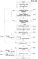
- FIG. 2A A series of operations of the monitoring system in the working machine 1 and the monitoring device 30 will be described below using FIG. 2A .
- the controller 11 After the process of canceling the monitoring mode of the working machine 1, in a state where the monitoring mode is canceled, for example, in the normal mode, the controller 11 checks whether the operation member 9 operating the working device 4 and the traveling device 5 is operated (step S11). In particular, the controller 11 confirms whether the operation member 9 is inputting a signal based on the operation of the operation member 9 to the controller 11.
- step S12 When a signal based on the operation of the operation member 9 is acquired, that is, when the operation member 9 is operated, the controller 11 controls the working device 4 and the traveling device 5 based on the operation of the operation member 9 (step S12).
- the controller 11 checks whether the working device 4 and the traveling device 5 have stopped operating (step S13). In particular, the controller 11 confirms whether the operation of the actuators and the like possessed by the working device 4 is stopped based on the signals input to the controller 11 from the working detector 4a through the on-board network N. The controller 11 confirms whether the operation of the actuators and the like possessed by the working device 4 has been stopped. Based on the signal obtained from the working detector 4a, the controller 11 determines, for example, if the rotation speed of the actuator or the like is zero, the operation of the working device 4 is stopped.
- the controller 11 determines that the working device 4 is operating when the rotational speed of the actuator or the like is other than zero, based on the signal acquired from the working detector 4a.
- the controller 11 also confirms whether the vehicle speed of the traveling device 5 is zero based on the signal input to the controller 11 from the traveling detector 5a through the on-board network N.
- the controller 11 checks whether the vehicle speed of the traveling device 5 is zero.
- the controller 11 determines that the operation of the traveling device 5 is stopped if the traveling speed of the traveling device 5 is zero based on the signal obtained from the traveling detector 5a.
- the controller 11 determines that the traveling device 5 is operating if the traveling speed of the traveling device 5 is other than zero, based on the signal obtained from the traveling detector 5a.
- the first communicator 12 transmits a parking signal to the second communicator 32 as a signal to indicate that the working machine 1 has stopped (step S14).
- the judgment analyzer 36 determines whether the working machine 1 is within the monitoring area.
- the first communicator 12 obtains the result of judgment (step S15).
- the judgment analyzer 36 obtains a threshold value previously stored in the second storage portion 35.
- the judgment analyzer 36 determines whether or not the working machine 1 is within the monitoring area based on the strength of the signals of the first communicator 12 and the second communicator 32 and the threshold value. In other words, if the strength of the signals of the first communicator 12 and the second communicator 32 is greater than the relevant threshold value, it is determined that the working machine 1 is within the monitoring area.
- the judgment analyzer 36 outputs the result of the determination to the second communicator 32.
- the second communicator 32 transmits the acquired result of the judgment to the first communicator 12.
- the first communicator 12 outputs the received judgment result to the display 13.
- the judgment result is stored in the first storage portion 15.
- the display 33 displays the followings (step S16), respectively.
- the display 13 displays an icon 61 on a portion of the normal screen D 1 indicating that the working machine 1 is within the range of the monitoring device 30 (step S17). For example, the display 13 transitions from the normal screen D1 to the screen D2 including the icon 61 indicating that the working machine 1 is within the range of the monitoring device 30.
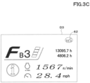
- the display 13 displays an icon 62, for example, an icon 62 indicating the first warning, in a portion of the normal screen D 1, warning that the working machine 1 is not within the range of the monitoring device 30 (step S18). For example, the display 13 transitions from the normal screen D1 to the screen D3 including the icon 62 indicating the first warning. This allows the operator to check whether the working machine 1 is within the monitoring area while on board the working machine 1. This allows the operator to easily guide the working machine 1 into the monitoring area, thus improving the effectiveness of the monitoring by the monitoring device 30.
- the controller 11 determines that the motor 3 has stopped based on the operator's turning of the engine key and the starter switch 19 outputting a signal to the starter relay 20 to stop the prime mover, or a signal input to the controller 11 from the rotating-speed detector 3a (step S19), and based on the received judgment results in step S15, it is determined whether the working machine 1 is within the monitoring area (S20).
- the controller 11 obtains a signal from the starter switch 19 or the rotating-speed detector 3a.
- the controller 11 determines whether the prime mover 3 is operating or stopped based on the signal.
- the controller 11 may be configured to determine that the prime mover 3 has stopped by both the signal obtained from the starter switch 19 and the signal obtained from the rotating-speed detector 3a.
- the controller 11 obtains the result of the determination of the judgment analyzer 36 from the first storage portion 15. Thereby, the controller 11 determines whether the working machine 1 is within the monitoring area or not.
- the display 13 transitions from the normal screen D1 to the screen D4 showing that the working machine 1 is within the range of the monitoring system 30, as shown in FIG. 4A .
- the monitoring system for the working machine 1 shifts to the monitoring mode (step S21).
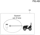
- step S22 the display 13 transitions from the normal screen D1 to the warning screen D5 showing a second warning that warns the operator that the working machine 1 is not within the range of the monitoring device 30, as shown in FIG. 4B.
- step S22 the operator to recognize again whether or not the working machine 1 is within the monitoring area when the prime mover 3 of the working machine 1 is stopped.
- step S23 The work machine is also stopped (step S23).
- FIG. 2B will be used to describe the operation of the release process of the monitoring mode in the working machine 1.
- the display 13 displays a request for a pass code input (step S32).
- the controller 11 obtains a signal from the starter switch 19 or the rotating-speed detector 3a.
- the controller 11 determines that the prime mover 3 is starting based on the signal, the controller 11 outputs, to the display 13a, signal that the prime mover 3 has started.
- the display 13 displays a request for a pass code input based on the signal.
- the instruction controller 11a instructs the monitor 33, via the first and second communication devices 12 and 32, to terminate the monitoring once started (step S34).
- the control device 11 obtains a signal based on the pass code inputted from the input device 14.
- the control device 11 also acquires information relating to the regular pass code stored in advance in the first storage portion 15.
- the controller 11 determines whether the pass code is a normal one or not based on the signal obtained from the input device 14 and the information obtained from the first storage portion 15.
- the instruction controller 11a outputs a termination signal instructing the first communicator 12 to terminate the monitoring once started.
- the first communicator 12 transmits the termination signal to the second communicator 32.
- the second communicator 32 outputs the received termination signal to the monitor 33.
- the monitor 33 obtains the termination signal, the monitor 33 terminates the monitoring.
- step S33 when the controller 11 recognizes that the pass code entered by the operator is not normal (step S33), the first communication device 31 sends a first warning signal to the second communicator 32 (step S35).
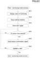
- FIG. 2C will be used to describe the operation of the process of the monitoring mode in the working machine 1.
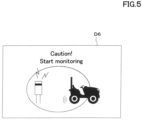
- the display 13 displays a screen D6 indicating that the monitoring mode has been switched to the monitoring mode as shown in FIG. 5 (step S41).
- the controller 11 shifts to background processing, for example, the working machine 1 is stopped (step S42).
- the instruction controller 11a instructs the monitor 33 to start monitoring via the first communication device 12 and second communication device (step S43).
- a start signal which is a signal instructing the monitor 33 to start monitoring, is sent from the first communicator 12 to the second communicator 32.
- the monitor 33 obtains the start signal, the monitor 33 starts imaging with the imaging portion 33a and obtaining a judgment result from the judgment analyzer 36.
- a status confirmation signal instructing monitoring by the monitor 33 is sent from the first communicator 12 to the second communicator 32 (step S45).
- the instruction controller 11a outputs a status confirmation signal instructing the monitoring by the monitor 33 to the first communicator 12 every fixed time.
- the first communicator 12 transmits the status confirmation signal to the second communicator 32.
- the second communicator 32 receives the status confirmation signal
- the second communicator 32 outputs the relevant status confirmation signal to the monitor 33.
- the monitor 33 obtains the status confirmation signal, the monitor 33 detects whether or not an abnormality has occurred based on the image captured by the imaging portion 33a and the determination by the judgment analyzer 36 whether or not the working machine 1 is within the area that can be monitored.
- step S46 When the controller 11 determines that the operator has operated the engine key to turn the engine key and the starter switch 19 has output a signal to the starter relay 20 to start the prime mover or that the prime mover 3 has been started from the rotating-speed detector 3a (step S46), the monitoring mode is terminated.
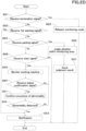
- FIG. 2D will be used to describe the operation of a series of processes in the monitoring device 30.
- the monitor 33 terminates the monitoring (step S52).
- the monitoring device 30 is released from the monitoring mode and shifts to the normal mode.
- the second communicator 32 transmits a call signal based on the first warning signal to the third communicator 41 (step S54).
- the second communicator 32 obtains the first warning signal
- the second communicator 32 outputs the first warning signal to the processor portion 31.
- the processor portion 31 maps the acquired first warning signal to the identification information of the monitoring device 30 as a call signal.
- the processor portion 31 outputs the call signal to the second communicator 32.
- the second communicator 32 transmits the acquired call signal to the third communicator 41.
- the judgment analyzer 36 determines whether the working machine 1 is in a monitorable area or not (step S56).
- the second communicator 32 transmits a signal based on the result of the judgment of the judgment analyzer 36 to the first communicator 12 (step S57).
- the second communicator 32 When the second communicator 32 receives a start signal without receiving any of the termination signal, the abnormality detection signal, or the parking signal (step S58), the monitoring of the working machine 1 is started, that is, the monitoring device 30 shifts to the monitoring mode (S59).
- the processor portion 31 determines whether there is an abnormality in the working machine 1 (step S61). In particular, based on the information acquired by the imaging portion 33a and whether the working machine 1 is within the monitoring area, the decision is made based on the information acquired by the imaging portion 33a and whether or not the working machine 1 is within the monitoring area.
- a signal based on the information determined to be the abnormality is sent from the second communicator 32 to the third communicator 41 (step S54).
- the monitor 33 outputs a second warning signal based on the abnormality with respect to the processor portion 31.
- the processor portion 31 corresponds with the second warning signal and the identification information of the monitoring device 30, and outputs the signal as a call signal to the second communicator 32.
- the second communicator 32 transmits the calling signal to the third communicator 41.
- the judgment analyzer 36 determines whether the working machine 1 is in a monitorable area based on the RSSI.
- the first communicator 12 and the second communicator 32 may communicate wirelessly by light.
- the first communicator 12 and the second communicator 32 each transmit a signal with a light emission pattern.
- the judgment analyzer 36 determines whether or not the working machine 1 is in a monitorable area based on the intensity of the light obtained by the second communicator 32 from the first communicator 12 and a threshold value stored in the second storage portion 35 in advance. This eliminates the need for a new configuration, since the configuration described above can be applied to the lamp provided by the current working machine 1 as the first communicator 12. For this reason, the monitoring system for the working machine 1 as described above can be easily introduced.
- the information including the threshold values stored in the first storage portion 15 may be configured to allow the settings to be changed by operating the display 13 or the input device 14.
- the information including the threshold values stored in the second storage portion 35 may be configured to allow the settings to be changed from a mobile terminal or the like with relatively high computing power, including a PC, via the server 40.
- the second communicator 32 transmits the calling signal to the server 40 when it receives the first or second warning signal, but may be configured to warn the user by means of the warning portion, if the monitoring device 30 is provided with a warning portion.
- the warning portion may be, for example, an alarm that warns the user with a warning sound or with a light.
- the monitoring system for the working machine 1 is provided with a first communicator 12, a second communicator 32, a monitor 33, a first communicator 12, a judgment analyzer 36, and an instruction controller 11a.
- This enables the working machine 1 to be monitored after determining whether the working machine 1 is within the monitoring area of the monitoring device 30. Therefore, the working machine 1 can be monitored when the working machine 1 is within the monitoring area, that is, when the monitoring of the monitoring device 30 is effective.
- the instruction controller 11a instructs the monitor 33 to monitor the working machine 1. This allows the monitoring by the monitor 33 of the monitoring device 30 to begin once the working machine 1 is within the monitoring area and the running of the working machine 1 has stopped. For this reason, even when the working machine 1 stops traveling and working is interrupted, the monitoring of the working machine 1 by the monitoring device 30 can be enabled without the need for any special operation.
- the instruction controller 11a instructs the monitor 33 to monitor the working machine 1. This allows the monitoring by the monitor 33 of the monitoring device 30 to begin once the working machine 1 is within the monitoring area and the working machine 1 has stopped traveling and working. Thus, even when the operator stops the working machine 1 in the agricultural field 50 and moves away from the working machine 1, the monitoring of the working machine 1 by the monitoring device 30 can be enabled without requiring any special operation.
- the instruction controller 11a instructs the monitor 33 to terminate the monitoring once started. This allows the monitoring by the monitoring device 30 to terminate when the operator activates the prime mover 3 of the working machine 1, that is, when the operator is in possession of a regular engine key. This prevents the authorized operator of the working machine 1 from being falsely reported by the monitoring device 30, and if the operator is an authorized operator, the monitoring mode can be easily terminated.
- the working machine 1 has an input device 14 and a control device 11, and the first communicator 12 outputs a signal to the second communicator 32 in which the indicator 11a instructs the second communicator 32 to terminate the monitoring of the monitor 33 when the control device 11 determines that the pass code entered into the input device 14 is normal.
- This enables the termination of the monitoring mode to prohibit the termination of the monitoring mode by a person other than an authorized operator, since the termination of the monitoring mode requires a regular engine key and a regular pass code.
- the working machine 1 has the display 13, and the display 13 displays the first warning, which is the result of the decision of the judgment analyzer 36. This allows the operator to check whether the working machine 1 is within the monitoring area while on board the working machine 1. This allows the operator to easily guide the working machine 1 into the monitoring area, thus improving the effectiveness of the monitoring by the monitoring device 30.
- the display 13 displays a second warning that is the result of the judgment analyzer 36 and is different from the first warning. This allows the operator to recognize again whether the working machine 1 is within the monitoring area when the prime mover 3 of the working machine 1 has been stopped. Thus, the operator can improve his or her recognition of the fact that the working machine 1 is out of the monitoring area if the working machine 1 is out of the monitoring area.
- the second communicator 32 outputs a signal based on the abnormality to the outside when the monitor 33 detects the abnormality.
- a security guard or a monitoring drone can be called from the external network.
- a mobile terminal or other device possessed by an authorized operator can be notified of the abnormality. Therefore, even if an abnormality occurs, such as an unauthorized operator operating the working machine 1 or an intruder stealing the working machine 1, it is possible to warn against such an act.
- the second communicator 32 outputs a signal to the outside to report that the pass code entered into the input device 14 is not normal if the control device 11 determines that the pass code entered into the input device 14 is not normal.
- This allows a security guard or surveillance drone to be called from an external network if the pass code entered into the input device 14 is incorrect.
- a mobile terminal or other device possessed by an authorized operator can be notified of the abnormality.
- the monitoring device 30 has at least one of the following: the air temperature sensor 34a, the humidity sensor 34b, the light intensity sensor 34c, and the wind speed sensor 34d. This allows the working machine 1 to be monitored by using a field server that monitors the condition of the agricultural field 50.
- the first communicator 12 and the second communicator 32 output and receive signals by radio waves. Thereby, the configuration described above does not require a new configuration because the first communicator 12, which is the wireless communication means provided by the current working machine 1, can be applied. For this reason, the monitoring system for the working machine 1 described above can be easily introduced.
- the first communicator 12 and the second communicator 32 output and receive signals by means of optical signals. In this manner, the configuration described above does not require a new configuration, since the lamp provided by the current working machine 1 can be applied as the first communicator 12. For this reason, the monitoring system for the working machine 1 as described above can be easily introduced.
Landscapes
- Engineering & Computer Science (AREA)
- Mechanical Engineering (AREA)
- Transportation (AREA)
- Chemical & Material Sciences (AREA)
- Combustion & Propulsion (AREA)
- Business, Economics & Management (AREA)
- Physics & Mathematics (AREA)
- General Physics & Mathematics (AREA)
- Tourism & Hospitality (AREA)
- Health & Medical Sciences (AREA)
- General Health & Medical Sciences (AREA)
- General Business, Economics & Management (AREA)
- Theoretical Computer Science (AREA)
- Economics (AREA)
- Human Resources & Organizations (AREA)
- Marketing (AREA)
- Primary Health Care (AREA)
- Strategic Management (AREA)
- Mining & Mineral Resources (AREA)
- Animal Husbandry (AREA)
- Agronomy & Crop Science (AREA)
- Life Sciences & Earth Sciences (AREA)
- Marine Sciences & Fisheries (AREA)
- Human Computer Interaction (AREA)
- Signal Processing (AREA)
- Emergency Management (AREA)
- Multimedia (AREA)
- Child & Adolescent Psychology (AREA)
- Computer Security & Cryptography (AREA)
- Development Economics (AREA)
- Educational Administration (AREA)
- Alarm Systems (AREA)
- Management, Administration, Business Operations System, And Electronic Commerce (AREA)
- Closed-Circuit Television Systems (AREA)
- Burglar Alarm Systems (AREA)
- Combines (AREA)
- Component Parts Of Construction Machinery (AREA)
Description
- The present invention relates to a monitoring system for a working machine.
- A method of preventing theft of a vehicle by issuing an alarm in response to changes in an image captured by an on-board camera is previously known as
Patent Document 1. - The car security device of
Patent Document 1 is characterized by including an on-board camera, a motion detector portion configured to detect whether movement has occurred in an image captured by the on-board camera, a controller portion configured to drive the on-board camera at regular intervals and to take a predetermined countermeasure when a movement is detected in the image captured by the on-board camera. - [Patent Document 1]
Japanese Unexamined Patent Publication No. 2008-155862 - Document
US 2005/017855 A1 describes a system for providing a virtual vehicle boundary. The system includes a method for activating a virtual fence for use with a delivery vehicle. The method comprises steps of detecting a protection event, determining that the protection event is an activation event, and activating a selected virtual fence based the activation event. - The car security device of the
patent document 1 has an on-board camera, and a predetermined countermeasure is taken when a movement occurs in the image captured by the on-board camera. However, since the monitoring range of the on-board camera is limited to the imaging angle of the on-board camera, conventional anti-theft technology as disclosed in thepatent document 1 has been unable to detect anomalies when anomalies occur outside the monitoring range of the on-board camera. In addition, when multiple cameras are used to expand the imaging angle in order to solve this problem, the power consumption of the batteries installed in the working machine and the like is increased, which may cause the batteries to run dry. - The present invention is made to solve the problems of the conventional technique, and intends to provide a monitoring system for a working machine configured to easily monitor the working machine.
- Technical means of the present invention for solving this technical problem is defined in the independent claims. Preferred embodiments are defined in the dependent claims.
- A monitoring system for a working machine, includes a first communicator device to communicate in wireless, the first communicator device being provided on the working machine including a working device and a traveling device, a second communicator device to communicate with the first communicator device in wireless, the second communicator device being provided on a monitoring device installed in an agricultural field, a monitor to monitor the agricultural field, the monitor being provided on the monitoring device, a judgment analyzer to judge whether the working machine is in a monitoring area based on intensities of signals of the first communicator device and the second communicator device, and an instruction controller to instruct the monitor to start monitoring when the judgment analyzer determines that the working machine is in the monitoring area of the monitor.
- The instruction controller instructs the monitor to start monitoring when the judgment analyzer determines that the working machine is in the monitoring area and the traveling device stops.
- The instruction controller instructs the monitor to start monitoring when the judgment analyzer determines that the working machine is in the monitoring area and the working device stops.
- The instruction controller instructs the monitor to stop monitoring when the judgment analyzer determines that the working machine is in the monitoring area and a prime mover provided in the working machine is in operation.
- The working machine includes an input device to which a pass code is input, and a controller to judge whether the pass code input to the input device is correct. The first communicator device outputs, to the second communicator device, a signal ordering the instruction controller to instruct the monitor to stop monitoring when the controller determines that the pass code input to the input device is correct.
the working machine includes a display to display a state of the working machine, and the display displays a first warning that represents a judgment result of the judgment controller. - The display displays a second warning that represents the judgment result of the judgment controller separately from the first warning when the judgment analyzer determines that the working machine is out of the monitoring area and the prime mover provided in the working machine stops.
- When the monitor detects abnormality, the second communicator device outputs a signal based on the abnormality to outside.
- The second communicator device outputs, to outside, a signal notifying that the pass code is incorrect when the controller determines that the pass code input to the input device is incorrect.
- The monitoring device includes at least one of a temperature sensor to measure temperature in the agricultural field, a humidity sensor to measure humidity in the agricultural field, a light intensity sensor to measure intensity of light in the agricultural field, and a wind speed sensor to measure a speed of wind in the agricultural field.
- The first communicator device and the second communicator device outputs and receives the signal with a radio wave.
- The first communicator device and the second communicator device outputs and receives the signal with an optical signal.
- A monitoring system for a working machine, includes a first communicator device to communicate in wireless, the first communicator device being provided on the working machine including a working device and a traveling device, a second communicator device to communicate with the first communicator device in wireless, the second communicator device being provided on a monitoring device installed in an agricultural field, a monitor to monitor the agricultural field, the monitor being provided on the monitoring device, a judgment analyzer to judge whether the working machine is in a monitoring area based on intensities of signals of the first communicator device and the second communicator device, and an instruction controller to instruct the monitor to start monitoring when the judgment analyzer determines that the working machine is in the monitoring area of the monitor. The instruction controller instructs the monitor to stop monitoring when the judgment analyzer determines that the working machine is in the monitoring area and a prime mover provided in the working machine is in operation.
- According to the present invention, it is easy to monitor the working machine.
-
-
FIG. 1 is an overall view of a monitoring system for a working machine. -
FIG. 2A is a view showing a sequential flow of the monitoring system in the working machine. -
FIG. 2B is a view showing a flow of the monitoring system in the working machine in releasing a monitoring mode. -
FIG. 2C is a view showing a flow of the monitoring system in the working machine in the monitoring mode. -
FIG. 2D is a view showing a sequential flow of the monitoring system in a monitor device. -
FIG. 3A is a view showing a normal screen displayed on a display. -
FIG. 3B is a view showing a screen displayed on the display, which represents the working machine is in a monitoring area. -
FIG. 3C is a view showing a screen indicating a first warning, which is displayed on the display. -
FIG. 4A is a view showing a pop-up screen displayed on the display, which represents the working machine is in the monitoring area. -
FIG. 4B is a view showing a pop-up screen indicating a second warning, which is displayed on the display. -
FIG. 5 is a view showing a pop-up screen indicating a monitoring mode starts, which is displayed on the display. - Hereinafter, an embodiment of the present invention will be described with appropriate reference to the drawings.
-
FIG. 1 is an overall view of a monitoring system for a workingmachine 1. The monitoring system for theworking machine 1 is a system for monitoring theworking machine 1. The monitoring system for theworking machine 1 is a monitoring system of theworking machine 1, wherein the monitoring device (field server) 30 installed in the agricultural field 50 detects a dynamic abnormality, such as an intrusion of a suspicious person or the like into the monitored area, or a movement of theworking machine 1 out of the monitored area, by dispatching security guards, monitoring drones, and the like to themonitoring device 30 or the vicinity of themonitoring device 30, thereby confirming any abnormality and warning suspicious persons. - The working
machine 1 is agricultural machinery and the like that performs work including plowing and harvesting crops in the agricultural field 50, and the agricultural machinery is a tractor, a combine, a rice transplanter and the like. Thetractor 1, which is one of the agricultural machinery, will be taken as an example below. Thetractor 1 can be provided with aworking device 4 such as, for example, a cultivator, a mower, a tedder, a rake, and the like. - First, the overall configuration of the
tractor 1 will be described. - As shown in
FIG. 1 , thetractor 1 is provided with a traveling vehicle (traveling body) having a travelingdevice 5 and a prime mover (driver portion) 3, such as a diesel engine and the like. - The
tractor 1 is provided with acontroller 11, a first communicator (first communicator device) 12, adisplay 13, and aninput device 14. Thetractor 1 is also provided with a rotating-speed detector 3a, a travelingdetector 5a, a workingdetector 4a, astarter switch 19, and astarter relay 20. Theprime mover 3, the workingdevice 4, the travelingdevice 5, thecontroller 11, thefirst communicator 12, thedisplay 13, theinput device 14, the rotating-speed detector 3a, the workingdetector 4a, the travelingdetector 5a, thestarter switch 19, and thestarter relay 20 are connected by an on-board network N such as CAN. In other words, for example, the devices connected by the on-board network N, including theprime mover 3, the workingdevice 4 and the travelingdevice 5, can output and acquire information between the devices on the on-board network N. For example, thecontroller 11 can obtain the number of revolutions of theprime mover 3 from the rotating-speed detector 3a. Thecontroller 11 can also obtain the vehicle speed of the travelingdevice 5 from the travelingdetector 5a. Thecontroller 11 can also acquire information such as the operating state of the workingdevice 4 from the workingdetector 4a. - The
controller 11 includes a CPU or the like and performs various controls relating to the workingmachine 1. Thecontroller 11 also has afirst storage portion 15. Thefirst storage portion 15 is a non-volatile memory or the like and stores various information. Thefirst storage portion 15 stores, for example, various application software. - The
first communicator 12 is, for example, a device configured to communicate with a second communicator (second communicator device) 32 installed in themonitoring device 30. Thefirst communicator 12 is a device configured to communicate in a short distance or a long distance. For example, thefirst communicator 12 communicates wirelessly with thesecond communicator 32 with Bluetooth (a registered trademark) Low Energy and the like in the Bluetooth (a registered trademark) specification of the IEEE802.15.1 series of communication standards. Hereinafter, for convenience of explanation, Bluetooth (a registered trademark) Low Energy will be referred to as "BLE". - The
display 13 is provided around theoperator seat 8 of the workingmachine 1 and is a screen for displaying various information about the workingmachine 1. Thedisplay 13 can display, for example, the number of revolutions of theprime mover 3, the speed of the travelingdevice 5, and the like. In particular, thedisplay 13 can display screens D1 to D6 as shown inFIG. 3A to FIG. 5 . - The
input device 14 is acode input device 14 such as a numeric keypad or the like capable of entering a pass code (certification information). When an operator operates theinput device 14 and inputs a pass code, the pass code is output as a signal. The signal output from theinput device 14 is input to thecontroller 11. The configuration may be such that the pass code can be entered by operating thedisplay 13 in the same manner as a numeric keypad, for example, thedisplay 13 may be configured to serve as aninput device 14. In particular, thedisplay portion 13 provided in the workingmachine 1 may be like a touch panel on which a numeric keypad or the like similar to theinput device 14 is displayed and a certification code is entered from thedisplay portion 13. In such a case, thedisplay 13 outputs a signal based on the pass code entered into thedisplay 13 to thecontroller 11. - The rotating-
speed detector 3a is a device for detecting the number of revolutions of theprime mover 3. In other words, the rotating-speed detector 3a can detect whether theprime mover 3 is starting or not. The rotating-speed detector 3a is provided in theprime mover 3 and includes a sensor or the like that detects the number of revolutions of theprime mover 3. The rotating-speed detector 3a can output a signal based on the number of revolutions detected by the rotating-speed detector 3a to thecontroller 11 through the on-board network N. In other words, thecontroller 11 can obtain the number of revolutions of theprime mover 3 from the rotating-speed detector 3a. The rotating-speed detector 3a can be any type of the rotating-speed detector 3a that is configured to detect whether theprime mover 3 is starting or not. - The working
detector 4a is a device for detecting a state of an actuator and the like provided in the workingdevice 4. In detail, the workingdetector 4a detects, for example, the number of rotations of the actuator provided in the workingdevice 4, the rotational speed of the actuator, and the like. In other words, the workingdetector 4a can detect whether the workingdevice 4 is operating or not. The workingdetector 4a is provided in the workingdevice 4 and includes a sensor or the like that detects the number of rotations of the actuator, the rotational speed of the actuator, and the like. The workingdetector 4a can output a signal based on the information detected by the workingdetector 4a to thecontroller 11 through the on-board network N. The workingdetector 4a can also output a signal based on the information detected by the workingdetector 4a to thecontroller 11. In other words, thecontroller 11 can obtain the status of the workingdevice 4 from the workingdetector 4a. The workingdetector 4a can be any type of workingdetector 4a that is capable of detecting whether the workingdevice 4 is operating or not. - The traveling
detector 5a is a device that detects the traveling speed (ground speed) of the workingmachine 1, that is, the speed of the travelingdevice 5. In other words, the travelingdetector 5a can detect whether the travelingdevice 5 is operating or not. The travelingdetector 5a is provided in the travelingdevice 5 and includes a vehicle speed sensor or the like that detects the speed of the workingmachine 1. The travelingdetector 5a can output a signal based on the traveling speed detected by the travelingdetector 5a to thecontroller 11 through the on-board network N. In other words, thecontroller 11 can obtain the travel speed of the workingmachine 1 from the travelingdetector 5a. The travelingdetector 5a can be any type of unit capable of detecting whether the travelingdevice 5 is operating or not. - The
starter switch 19 is a switch for starting theprime mover 3. When an operator inserts an engine key into a key cylinder provided around the operator seat and turns the engine key, thestarter switch 19 outputs a signal to thestarter relay 20 to start the prime mover. - The
starter relay 20 is a component for starting theprime mover 3. When a signal for starting the prime mover is input from thestarter switch 19 to thestarter relay 20, thestarter relay 20 starts theprime mover 3. The starting of the prime mover, which is one of driving of the prime mover, is not limited to a mechanical type (key cylinder type) where the engine key is inserted into the key cylinder and thestarter relay 20 is turned on, but may be a smart entry type where the starting of the prime mover is permitted or prohibited by radio communication. - The monitoring device (field server) 30 is a device for collecting information about the agricultural field 50 and the crops to be grown in the agricultural field 50. The
monitoring device 30 is installed in the agricultural field 50 where the crops are grown. Themonitoring device 30 has aprocessor portion 31, asecond communicator 32, amonitor 33, and aninformation collector 34. - The
processor portion 31 includes a CPU and the like, and processes the information (data) acquired by themonitor 33 and theinformation collector 34. Theprocessor portion 31 also has asecond storage portion 35. Thesecond storage portion 35 is a non-volatile memory or the like, and stores various information, including information processed by theprocessor portion 31. Thethird communicator 41 may, for example, communicate wirelessly with thesecond communicator 32 by means of a cellular phone communication network, a data communication network, a cellular phone communication network, or the like. Thethird communicator 41 receives a call signal sent by thesecond communicator 32 of themonitoring device 30. Based on the call signal and the location information of themonitoring device 30 stored in thethird storage portion 42, it calls the guards, the monitoring drone and the like to the agricultural field 50. Theserver 40 does not call the guards, the monitoring drone and the like, but may be configured to notify the operator of the alarm and the location information of themonitoring device 30 to a mobile terminal such as a PC or a smart phone possessed by the operator. - The
second communicator 32 is, for example, a device for communicating with thefirst communicator 12 and theserver 40 installed in the workingmachine 1. Thesecond communicator 32 is a device that communicates over short and long distances. Thesecond communicator 32 communicates wirelessly with thefirst communicator 12, for example, by BLE or the like. Thesecond communicator 32 also communicates wirelessly with theserver 40 and the like by means of a cellular phone communication network, a data communication network, a cellular phone communication network, and Wi-Fi (Wireless Fidelity, a registered trademark) of the IEEE 802.11 series, which is a communication standard, and the like. - The
monitor 33 includes electrical and electronic components, a program stored in thesecond storage portion 35, and the like, and monitors a condition in the agricultural field 50, including the workingmachine 1. In the following description, it is referred to as "monitoring" that themonitor 33 "performs the imaging by theimaging portion 33a" and "obtains the result of the judgment of thejudgment analyzer 36". Themonitor 33 has an imaging portion (imaging device) 33a. Theimaging portion 33a is an image sensor such as a CCD or CMOS sensor that captures a state in the agricultural field 50 and outputs the image data. Theimaging portion 33a is mounted at a position where, for example, the area including the workingmachine 1 and the crop is the imaging area. Theimaging portion 33a, for example, captures a plurality of images by a single imaging operation. Theimaging portion 33a may also capture video images including audio. - The
information collector 34 includes at least one or more of, for example, anair temperature sensor 34a, ahumidity sensor 34b, anlight intensity sensor 34c, and awind speed sensor 34d. Thetemperature sensor 34a is a sensor that measures, for example, the temperature in the agricultural field 50 (outdoor temperature) as a change in resistance of the thermistor. Thehumidity sensor 34b is a sensor that measures, for example, the humidity of the soil within the agricultural field 50 based on the change in resistance of the current flowing through the soil. Thelight intensity sensor 34c is a sensor for measuring intensity of light within the agricultural field 50, for example, based on the light emitted on the infrared light emitting device. Thewind speed sensor 34d is a sensor that measures the wind speed within the agricultural field 50. Theinformation collector 34 is not limited to thetemperature sensor 34a, thehumidity sensor 34b, thelight intensity sensor 34c, and thewind speed sensor 34d, but may be any sensor that collects information within the agricultural field 50. In other words, by using a field server having theinformation collector 34 and monitoring the condition of the agricultural field 50, the workingmachine 1 can be monitored. - The
server 40 has athird communicator 41 and athird storage portion 42. Thethird communicator 41 allows theserver 40 to communicate wirelessly with themonitoring device 30 and the outside. Thethird communicator 41, for example, communicates wirelessly with thesecond communicator 32 of themonitoring device 30 and the outside by means of a cellular phone communication network, a data communication network, a cellular phone communication network, and Wi-Fi of the IEEE 802.11 series, which is a communication standard. - The
third storage portion 42 is a non-volatile memory or the like, and stores various information, including information received by thethird communicator 41 and position information of themonitoring device 30. The configuration of the position information of themonitoring device 30 may be stored in thethird storage portion 42 in advance, or themonitoring device 30 may be provided with a position detector, and the position information detected by the position detector is transmitted from thesecond communicator 32 to thethird communicator 41. The position detector is a device that detects its own position (positioning information including latitude and longitude) by a satellite positioning system (Global Positioning System, Galileo, GLONASS, and the like). - Now, the monitoring system for the working
machine 1 can be switched between a normal mode and a monitoring mode. The normal mode is the mode used when the operator is on board the workingmachine 1 and does not require external monitoring. The monitoring mode is a mode for monitoring the workingmachine 1 when the operator is parking the workingmachine 1 in the agricultural field 50, for example. The switching between the normal mode and the monitoring mode is based on whether the workingmachine 1 is parked and whether the workingmachine 1 is within the monitoring area (monitoring range) of themonitoring device 30. - In particular, the
processor portion 31 has thejudgment analyzer 36. Thejudgment analyzer 36 includes a program or the like stored in thesecond storage portion 35, and determines whether the workingmachine 1 is within the monitoring area of themonitor 33. Thejudgment analyzer 36 is possessed, for example, by theprocessor portion 31 of themonitoring device 30. In particular describing thejudgment analyzer 36, thejudgment analyzer 36 determines whether the workingmachine 1 is in the monitorable area based on, for example, a received signal strength indicator (RSSI). In particular, based on the monitorable area of themonitor 33, the distance between thefirst communicator 12 and thesecond communicator 32 is calculated according to a preset threshold of the signal strength. Thereby, it is determined whether the workingmachine 1 is in the monitorable area or not. In other words, thejudgment analyzer 36 determines whether the workingmachine 1 is within the monitoring area based on the strength of the signals of thefirst communicator 12 and thesecond communicator 32. Thejudgment analyzer 36 may be constituted of thecontroller 11 of the workingmachine 1 or by theserver 40, or any other configuration. The result of the determination of thejudgment analyzer 36 is transmitted from thesecond communicator 32 to thefirst communicator 12. - The
processor portion 31 corresponds to the identification information of themonitoring device 30 and each of the information acquired by themonitor 33 and theinformation collector 34. In particular, for example, when thesecond communicator 32 receives a first warning signal from thefirst communicator 12 or when thesecond communicator 32 receives a second warning signal that is output when themonitor 33 obtains information and detects an abnormality, theprocessor portion 31 associates the first warning signal or the second warning signal with themonitoring device 30 as a signal for calling the outside guards, the monitoring drone and the like. In detail, theprocessor portion 31 obtains the first and second warning signals from thesecond communicator 32, and maps the first or second warning signal to the identification information of themonitoring device 30 as a call signal. Theprocessor portion 31 outputs the calling signal to thesecond communicator 32. - The
control device 11 determines whether the input pass code is a normal one or not based on the information stored in thefirst storage portion 15. If the pass code is an unnormal one, thefirst communicator 12 obtains a first warning signal, which is a signal that the pass code is unnormal. Thefirst communicator 12 transmits the first warning signal to thesecond communicator 32 of themonitoring device 30. - The
controller 11 has aninstruction controller 11a. Theinstruction controller 11a includes a program or the like stored in thefirst storage portion 15, and instructs themonitor 33 to monitor the workingmachine 1 when the workingmachine 1 is in the monitorable area. Theinstruction controller 11a is, for example, possessed by thecontroller 11 of the workingmachine 1. Specifically describing theinstruction controller 11a, when thefirst communicator 12 receives the result of the determination that the workingmachine 1 is in the monitorable area, thefirst communicator 12 and thesecond communicator 32 output a start signal, which is a signal instructing themonitor 33 to start monitoring, via thefirst communicator 12 and thesecond communicator 32. When thesecond communicator 32 receives the start signal, themonitor 33 starts monitoring. In other words, themonitor 33 begins to capture images by theimaging portion 33a of themonitor 33 and to acquire the results of the decision from thejudgment analyzer 36. This enables the monitoring of the workingmachine 1 after determining whether or not the workingmachine 1 is within the monitoring area of themonitoring device 30. Therefore, the workingmachine 1 can be monitored when the workingmachine 1 is within the monitoring area, that is, when the monitoring of themonitoring device 30 is effective. Theinstruction controller 11a instructs themonitor 33 to terminate the monitoring when theprime mover 3 starts when themonitor 33 is monitoring the workingmachine 1. In particular, in the case where themonitor 33 performs the monitoring, thecontroller 11 determines whether theprime mover 3 has started based on the signal output from thestarter switch 19 or the signal output from the rotating-speed detector 3a. When thecontroller 11 determines that theprime mover 3 has started, a termination signal is transmitted from thecontroller 11 to themonitor 33 via thefirst communicator 12 and thesecond communicator 32, indicating the end of the monitoring. In other words, theindication portion 11a instructs themonitor 33 to terminate the monitoring once started. Theinstruction controller 11a also instructs themonitor 33 to detect an abnormality at regular intervals in the state where themonitor 33 is monitoring. In particular, theinstruction controller 11a transmits a status confirmation signal to themonitor 33 via thefirst communicator 12 and thesecond communicator 32 at regular intervals. - The
first communicator 12 transmits to thesecond communicator 32, for example, a first warning signal, which is a signal indicating that the pass code entered into theinput device 14 is unnormal, when the pass code is unnormal. When thecontrol device 11 determines that the workingmachine 1 has stopped, thefirst communicator 12 transmits, to thesecond communicator 32, a parking signal, which is a signal indicating that the workingmachine 1 has stopped. - When the
second communicator 32 receives the first warning signal from thefirst communicator 12 or acquires the second warning signal that is output when themonitor 33 detects an abnormality, thesecond communicator 32 outputs the first and second warning signals to theprocessor portion 31. When thesecond communicator 32 obtains a call signal from theprocessor portion 31, thesecond communicator 32 transmits the call signal to thethird communicator 41. - In the case of monitoring the working
machine 1, themonitor 33 detects a moving object in the agricultural field 50, including the area around the work machine, based on the image data output by theimaging portion 33a. Thereby, themonitor 33 determines whether or not there is an abnormality, such as the presence of an intruder attempting to steal the workingmachine 1, in the vicinity of the working machine. In addition, themonitor 33 obtains from thejudgment analyzer 36 the result of determining whether or not the workingmachine 1 is within the monitoring area, and determines whether or not there is an abnormality, such as the workingmachine 1 being moved. When themonitor 33 acquires a start signal indicating the start of monitoring, themonitor 33 starts the monitoring. In particular, themonitor 33 starts imaging with theimaging portion 33a. Themonitor 33 also begins to acquire a judgment result from thejudgment analyzer 36 as to whether the workingmachine 1 is within the monitoring area or not. When themonitor 33 obtains a status confirmation signal to confirm whether or not there is an abnormality in the agricultural field 50, themonitor 33 detects an abnormality whether or not an abnormality has occurred based on the image output by theimaging portion 33a and the judgment result, as described above. If themonitor 33 determines that there is an abnormality, themonitor 33 outputs a second warning signal based on the abnormality to thesecond communicator 32. When themonitor 33 obtains the start signal, themonitor 33 may be configured to "capture an image with theimaging portion 33a", "acquire a judgment result from thejudgment analyzer 36", and "detect the abnormality". In other words, the configuration may be such that themonitor 33 includes in the "monitoring" the actions up to the point of detecting the abnormality based on the "imaging by theimaging portion 33a" and the "judgment result". - A series of operations of the monitoring system in the working
machine 1 and themonitoring device 30 will be described below usingFIG. 2A . - After the process of canceling the monitoring mode of the working
machine 1, in a state where the monitoring mode is canceled, for example, in the normal mode, thecontroller 11 checks whether the operation member 9 operating the workingdevice 4 and the travelingdevice 5 is operated (step S11). In particular, thecontroller 11 confirms whether the operation member 9 is inputting a signal based on the operation of the operation member 9 to thecontroller 11. - When a signal based on the operation of the operation member 9 is acquired, that is, when the operation member 9 is operated, the
controller 11 controls the workingdevice 4 and the travelingdevice 5 based on the operation of the operation member 9 (step S12). - When no signal based on the operation of the operation member 9 is acquired, for example, when the operation member 9 is not operated, the
controller 11 checks whether the workingdevice 4 and the travelingdevice 5 have stopped operating (step S13). In particular, thecontroller 11 confirms whether the operation of the actuators and the like possessed by the workingdevice 4 is stopped based on the signals input to thecontroller 11 from the workingdetector 4a through the on-board network N. Thecontroller 11 confirms whether the operation of the actuators and the like possessed by the workingdevice 4 has been stopped. Based on the signal obtained from the workingdetector 4a, thecontroller 11 determines, for example, if the rotation speed of the actuator or the like is zero, the operation of the workingdevice 4 is stopped. On the other hand, thecontroller 11 determines that the workingdevice 4 is operating when the rotational speed of the actuator or the like is other than zero, based on the signal acquired from the workingdetector 4a. Thecontroller 11 also confirms whether the vehicle speed of the travelingdevice 5 is zero based on the signal input to thecontroller 11 from the travelingdetector 5a through the on-board network N. Thecontroller 11 checks whether the vehicle speed of the travelingdevice 5 is zero. Thecontroller 11 determines that the operation of the travelingdevice 5 is stopped if the traveling speed of the travelingdevice 5 is zero based on the signal obtained from the travelingdetector 5a. On the other hand, thecontroller 11 determines that the travelingdevice 5 is operating if the traveling speed of the travelingdevice 5 is other than zero, based on the signal obtained from the travelingdetector 5a. - When the
controller 11 confirms the cessation of operation of the workingdevice 4 and the travelingdevice 5, thefirst communicator 12 transmits a parking signal to thesecond communicator 32 as a signal to indicate that the workingmachine 1 has stopped (step S14). - When the
second communicator 32 receives the parking signal, thejudgment analyzer 36 determines whether the workingmachine 1 is within the monitoring area. Thefirst communicator 12 obtains the result of judgment (step S15). In detail, thejudgment analyzer 36 obtains a threshold value previously stored in thesecond storage portion 35.
Thejudgment analyzer 36 determines whether or not the workingmachine 1 is within the monitoring area based on the strength of the signals of thefirst communicator 12 and thesecond communicator 32 and the threshold value. In other words, if the strength of the signals of thefirst communicator 12 and thesecond communicator 32 is greater than the relevant threshold value, it is determined that the workingmachine 1 is within the monitoring area. On the other hand, if the intensity of the signals of thefirst communicator 12 and thesecond communicator 32 is less than the threshold, it is determined that thefirst communicator 12 and thesecond communicator 32 are outside the monitoring area. Thejudgment analyzer 36 outputs the result of the determination to thesecond communicator 32. Thesecond communicator 32 transmits the acquired result of the judgment to thefirst communicator 12. Thefirst communicator 12 outputs the received judgment result to thedisplay 13. The judgment result is stored in thefirst storage portion 15. - Based on the judgment results stored in the
first storage portion 15, thedisplay 33 displays the followings (step S16), respectively. - When the working
machine 1 is within the monitoring area, as shown inFIG. 3B , thedisplay 13 displays anicon 61 on a portion of thenormal screen D 1 indicating that the workingmachine 1 is within the range of the monitoring device 30 (step S17). For example, thedisplay 13 transitions from the normal screen D1 to the screen D2 including theicon 61 indicating that the workingmachine 1 is within the range of themonitoring device 30. - When the working
machine 1 is not within the monitoring area, as shown inFIG. 3C , thedisplay 13 displays anicon 62, for example, anicon 62 indicating the first warning, in a portion of thenormal screen D 1, warning that the workingmachine 1 is not within the range of the monitoring device 30 (step S18). For example, thedisplay 13 transitions from the normal screen D1 to the screen D3 including theicon 62 indicating the first warning. This allows the operator to check whether the workingmachine 1 is within the monitoring area while on board the workingmachine 1. This allows the operator to easily guide the workingmachine 1 into the monitoring area, thus improving the effectiveness of the monitoring by themonitoring device 30. - The
controller 11 determines that themotor 3 has stopped based on the operator's turning of the engine key and thestarter switch 19 outputting a signal to thestarter relay 20 to stop the prime mover, or a signal input to thecontroller 11 from the rotating-speed detector 3a (step S19), and based on the received judgment results in step S15, it is determined whether the workingmachine 1 is within the monitoring area (S20). In detail, thecontroller 11 obtains a signal from thestarter switch 19 or the rotating-speed detector 3a. Thecontroller 11 determines whether theprime mover 3 is operating or stopped based on the signal. Thecontroller 11 may be configured to determine that theprime mover 3 has stopped by both the signal obtained from thestarter switch 19 and the signal obtained from the rotating-speed detector 3a. When thecontroller 11 determines that theprime mover 3 has stopped, thecontroller 11 obtains the result of the determination of thejudgment analyzer 36 from thefirst storage portion 15. Thereby, thecontroller 11 determines whether the workingmachine 1 is within the monitoring area or not. - When the working
machine 1 is within the monitoring area, thedisplay 13 transitions from the normal screen D1 to the screen D4 showing that the workingmachine 1 is within the range of themonitoring system 30, as shown inFIG. 4A . The monitoring system for the workingmachine 1 shifts to the monitoring mode (step S21). - On the other hand, if the working
machine 1 is not within the monitoring area, thedisplay 13 transitions from the normal screen D1 to the warning screen D5 showing a second warning that warns the operator that the workingmachine 1 is not within the range of themonitoring device 30, as shown inFIG. 4B (step S22). This allows the operator to recognize again whether or not the workingmachine 1 is within the monitoring area when theprime mover 3 of the workingmachine 1 is stopped. This allows the operator to improve recognition of the fact that the workingmachine 1 is out of the monitoring area if the workingmachine 1 is out of the monitoring area. The work machine is also stopped (step S23). - Next,
FIG. 2B will be used to describe the operation of the release process of the monitoring mode in the workingmachine 1. - When the monitoring system for the working
machine 1 is in the monitoring mode, when thecontroller 11 determines that the operator has operated the engine key to turn the engine key and thestarter switch 19 has output a signal to thestarter relay 20 to start the prime mover or that theprime mover 3 has been started from the rotating-speed detector 3a (step S31), thedisplay 13 displays a request for a pass code input (step S32). In particular, when the monitoring system for the workingmachine 1 is in the monitoring mode, thecontroller 11 obtains a signal from thestarter switch 19 or the rotating-speed detector 3a. When thecontroller 11 determines that theprime mover 3 is starting based on the signal, thecontroller 11 outputs, to the display 13a, signal that theprime mover 3 has started. Thedisplay 13 displays a request for a pass code input based on the signal. - When the
controller 11 recognizes that the operator operates theinput device 14 and that the input pass code is normal (step S33), theinstruction controller 11a instructs themonitor 33, via the first andsecond communication devices control device 11 obtains a signal based on the pass code inputted from theinput device 14. Thecontrol device 11 also acquires information relating to the regular pass code stored in advance in thefirst storage portion 15. Thecontroller 11 determines whether the pass code is a normal one or not based on the signal obtained from theinput device 14 and the information obtained from thefirst storage portion 15. When thecontrol device 11 determines that the input pass code is a normal pass code, theinstruction controller 11a outputs a termination signal instructing thefirst communicator 12 to terminate the monitoring once started. Thefirst communicator 12 transmits the termination signal to thesecond communicator 32. Thesecond communicator 32 outputs the received termination signal to themonitor 33. When themonitor 33 obtains the termination signal, themonitor 33 terminates the monitoring. - On the other hand, when the
controller 11 recognizes that the pass code entered by the operator is not normal (step S33), thefirst communication device 31 sends a first warning signal to the second communicator 32 (step S35). - Next,
FIG. 2C will be used to describe the operation of the process of the monitoring mode in the workingmachine 1. - When the monitoring mode is switched to the monitoring mode, the
display 13 displays a screen D6 indicating that the monitoring mode has been switched to the monitoring mode as shown inFIG. 5 (step S41). - The
controller 11 shifts to background processing, for example, the workingmachine 1 is stopped (step S42). - The
instruction controller 11a instructs themonitor 33 to start monitoring via thefirst communication device 12 and second communication device (step S43). In particular, a start signal, which is a signal instructing themonitor 33 to start monitoring, is sent from thefirst communicator 12 to thesecond communicator 32. When themonitor 33 obtains the start signal, themonitor 33 starts imaging with theimaging portion 33a and obtaining a judgment result from thejudgment analyzer 36. - After the monitoring system shifts to the monitoring mode, every time a certain amount of time passes (step S44), a status confirmation signal instructing monitoring by the
monitor 33 is sent from thefirst communicator 12 to the second communicator 32 (step S45). In particular described, theinstruction controller 11a outputs a status confirmation signal instructing the monitoring by themonitor 33 to thefirst communicator 12 every fixed time. Thefirst communicator 12 transmits the status confirmation signal to thesecond communicator 32. When thesecond communicator 32 receives the status confirmation signal, thesecond communicator 32 outputs the relevant status confirmation signal to themonitor 33. When themonitor 33 obtains the status confirmation signal, themonitor 33 detects whether or not an abnormality has occurred based on the image captured by theimaging portion 33a and the determination by thejudgment analyzer 36 whether or not the workingmachine 1 is within the area that can be monitored. - When the
controller 11 determines that the operator has operated the engine key to turn the engine key and thestarter switch 19 has output a signal to thestarter relay 20 to start the prime mover or that theprime mover 3 has been started from the rotating-speed detector 3a (step S46), the monitoring mode is terminated. - Next,
FIG. 2D will be used to describe the operation of a series of processes in themonitoring device 30. - When the
second communicator 32 receives a termination signal from the first communicator 12 (step S51), themonitor 33 terminates the monitoring (step S52). In other words, when thesecond communicator 32 receives a termination signal from thefirst communicator 12, themonitoring device 30 is released from the monitoring mode and shifts to the normal mode. - On the other hand, when the
second communicator 32 does not receive a termination signal from thefirst communicator 12 and receives the first warning signal (step S53), thesecond communicator 32 transmits a call signal based on the first warning signal to the third communicator 41 (step S54). In detail, when thesecond communicator 32 obtains the first warning signal, thesecond communicator 32 outputs the first warning signal to theprocessor portion 31. Theprocessor portion 31 maps the acquired first warning signal to the identification information of themonitoring device 30 as a call signal. Theprocessor portion 31 outputs the call signal to thesecond communicator 32. Thesecond communicator 32 transmits the acquired call signal to thethird communicator 41. - When the
second communicator 32 does not receive a termination signal and an abnormality detection signal, but receives a parking signal (step S55), thejudgment analyzer 36 determines whether the workingmachine 1 is in a monitorable area or not (step S56). - The
second communicator 32 transmits a signal based on the result of the judgment of thejudgment analyzer 36 to the first communicator 12 (step S57). - When the
second communicator 32 receives a start signal without receiving any of the termination signal, the abnormality detection signal, or the parking signal (step S58), the monitoring of the workingmachine 1 is started, that is, themonitoring device 30 shifts to the monitoring mode (S59). - When the
second communicator 32 receives a status confirmation signal from the first communicator 12 (step S60), based on the information obtained by themonitor 33, theprocessor portion 31 determines whether there is an abnormality in the working machine 1 (step S61). In particular, based on the information acquired by theimaging portion 33a and whether the workingmachine 1 is within the monitoring area, the decision is made based on the information acquired by theimaging portion 33a and whether or not the workingmachine 1 is within the monitoring area. - When the
processor portion 31 determines that there is an abnormality in the working machine 1 (step S62), a signal based on the information determined to be the abnormality is sent from thesecond communicator 32 to the third communicator 41 (step S54). In particular, themonitor 33 outputs a second warning signal based on the abnormality with respect to theprocessor portion 31. Theprocessor portion 31 corresponds with the second warning signal and the identification information of themonitoring device 30, and outputs the signal as a call signal to thesecond communicator 32. Thesecond communicator 32 transmits the calling signal to thethird communicator 41. - The above-described embodiments are illustrative in all respects and are not restrictive. For example, in this embodiment, since the
first communicator 12 and thesecond communicator 32 communicate wirelessly with thefirst communicator 12 by BLE or the like, thejudgment analyzer 36 determines whether the workingmachine 1 is in a monitorable area based on the RSSI. However, thefirst communicator 12 and thesecond communicator 32 may communicate wirelessly by light. For example, thefirst communicator 12 and thesecond communicator 32 each transmit a signal with a light emission pattern. In the case, thejudgment analyzer 36 determines whether or not the workingmachine 1 is in a monitorable area based on the intensity of the light obtained by thesecond communicator 32 from thefirst communicator 12 and a threshold value stored in thesecond storage portion 35 in advance. This eliminates the need for a new configuration, since the configuration described above can be applied to the lamp provided by the current workingmachine 1 as thefirst communicator 12. For this reason, the monitoring system for the workingmachine 1 as described above can be easily introduced. The information including the threshold values stored in thefirst storage portion 15 may be configured to allow the settings to be changed by operating thedisplay 13 or theinput device 14. The information including the threshold values stored in thesecond storage portion 35 may be configured to allow the settings to be changed from a mobile terminal or the like with relatively high computing power, including a PC, via theserver 40. In addition, in the above-described embodiment, thesecond communicator 32 transmits the calling signal to theserver 40 when it receives the first or second warning signal, but may be configured to warn the user by means of the warning portion, if themonitoring device 30 is provided with a warning portion. In such a case, the warning portion may be, for example, an alarm that warns the user with a warning sound or with a light. - As described above, the monitoring system for the working
machine 1 is provided with afirst communicator 12, asecond communicator 32, amonitor 33, afirst communicator 12, ajudgment analyzer 36, and aninstruction controller 11a. This enables the workingmachine 1 to be monitored after determining whether the workingmachine 1 is within the monitoring area of themonitoring device 30. Therefore, the workingmachine 1 can be monitored when the workingmachine 1 is within the monitoring area, that is, when the monitoring of themonitoring device 30 is effective. - If the
judgment analyzer 36 determines that the workingmachine 1 is within the monitoring area and the travelingdevice 5 has stopped, theinstruction controller 11a instructs themonitor 33 to monitor the workingmachine 1. This allows the monitoring by themonitor 33 of themonitoring device 30 to begin once the workingmachine 1 is within the monitoring area and the running of the workingmachine 1 has stopped. For this reason, even when the workingmachine 1 stops traveling and working is interrupted, the monitoring of the workingmachine 1 by themonitoring device 30 can be enabled without the need for any special operation. - If the
judgment analyzer 36 determines that the workingmachine 1 is within the monitoring area and the workingdevice 4 is stopped, theinstruction controller 11a instructs themonitor 33 to monitor the workingmachine 1. This allows the monitoring by themonitor 33 of themonitoring device 30 to begin once the workingmachine 1 is within the monitoring area and the workingmachine 1 has stopped traveling and working. Thus, even when the operator stops the workingmachine 1 in the agricultural field 50 and moves away from the workingmachine 1, the monitoring of the workingmachine 1 by themonitoring device 30 can be enabled without requiring any special operation. - If the
judgment analyzer 36 determines that the workingmachine 1 is within the monitorable area and theprime mover 3 provided in the workingmachine 1 is operating, theinstruction controller 11a instructs themonitor 33 to terminate the monitoring once started. This allows the monitoring by themonitoring device 30 to terminate when the operator activates theprime mover 3 of the workingmachine 1, that is, when the operator is in possession of a regular engine key. This prevents the authorized operator of the workingmachine 1 from being falsely reported by themonitoring device 30, and if the operator is an authorized operator, the monitoring mode can be easily terminated. - The working
machine 1 has aninput device 14 and acontrol device 11, and thefirst communicator 12 outputs a signal to thesecond communicator 32 in which theindicator 11a instructs thesecond communicator 32 to terminate the monitoring of themonitor 33 when thecontrol device 11 determines that the pass code entered into theinput device 14 is normal. This enables the termination of the monitoring mode to prohibit the termination of the monitoring mode by a person other than an authorized operator, since the termination of the monitoring mode requires a regular engine key and a regular pass code. - The working
machine 1 has thedisplay 13, and thedisplay 13 displays the first warning, which is the result of the decision of thejudgment analyzer 36. This allows the operator to check whether the workingmachine 1 is within the monitoring area while on board the workingmachine 1. This allows the operator to easily guide the workingmachine 1 into the monitoring area, thus improving the effectiveness of the monitoring by themonitoring device 30. - If the
judgment analyzer 36 determines that the workingmachine 1 is not in the monitored range and theprime mover 3 provided in the workingmachine 1 is stopped, thedisplay 13 displays a second warning that is the result of thejudgment analyzer 36 and is different from the first warning. This allows the operator to recognize again whether the workingmachine 1 is within the monitoring area when theprime mover 3 of the workingmachine 1 has been stopped. Thus, the operator can improve his or her recognition of the fact that the workingmachine 1 is out of the monitoring area if the workingmachine 1 is out of the monitoring area. - The
second communicator 32 outputs a signal based on the abnormality to the outside when themonitor 33 detects the abnormality. Thereby, if an abnormality occurs in the workingmachine 1 within the monitoring area, a security guard or a monitoring drone can be called from the external network. In addition, a mobile terminal or other device possessed by an authorized operator can be notified of the abnormality. Therefore, even if an abnormality occurs, such as an unauthorized operator operating the workingmachine 1 or an intruder stealing the workingmachine 1, it is possible to warn against such an act. - In addition, the
second communicator 32 outputs a signal to the outside to report that the pass code entered into theinput device 14 is not normal if thecontrol device 11 determines that the pass code entered into theinput device 14 is not normal. This allows a security guard or surveillance drone to be called from an external network if the pass code entered into theinput device 14 is incorrect. In addition, a mobile terminal or other device possessed by an authorized operator can be notified of the abnormality. Thus, if an unauthorized operator attempts to operate the workingmachine 1 or an intruder attempts to steal the workingmachine 1, and an unauthorized pass code is entered into theinput device 14, it is possible to warn against such an action. - The
monitoring device 30 has at least one of the following: theair temperature sensor 34a, thehumidity sensor 34b, thelight intensity sensor 34c, and thewind speed sensor 34d. This allows the workingmachine 1 to be monitored by using a field server that monitors the condition of the agricultural field 50. - The
first communicator 12 and thesecond communicator 32 output and receive signals by radio waves. Thereby, the configuration described above does not require a new configuration because thefirst communicator 12, which is the wireless communication means provided by the current workingmachine 1, can be applied. For this reason, the monitoring system for the workingmachine 1 described above can be easily introduced. - The
first communicator 12 and thesecond communicator 32 output and receive signals by means of optical signals. In this manner, the configuration described above does not require a new configuration, since the lamp provided by the current workingmachine 1 can be applied as thefirst communicator 12. For this reason, the monitoring system for the workingmachine 1 as described above can be easily introduced. - In the above description, the embodiment of the present invention has been explained. However, all the features of the embodiment disclosed in this application should be considered just as examples, and the embodiment does not restrict the present invention accordingly. A scope of the present invention is shown not in the above-described
-
- 1
- Vehicle body frame
- 3
- Rear wheel
- 4
- Working device
- 5
- Traveling device
- 11a
- Instruction controller
- 12
- First communicator device
- 13
- Indicator
- 14
- Input device
- 30
- Monitoring device
- 32
- Second communicator device
- 33
- Monitor
- 34a
- Temperature sensor
- 34b
- Humidity sensor
- 34c
- Light intensity sensor
- 34d
- Wind speed sensor
- 36
- Judgment analyzer
- 50
- Agricultural field
Claims (15)
- A monitoring system for a working machine (1), comprising:a first communicator device (12) to communicate wirelessly, the first communicator device (12) being provided on the working machine (1) including a working device (4) and a traveling device (5);a second communicator device (32) to communicate with the first communicator device (12) wirelessly, the second communicator device (32) being provided on a monitoring device (30) installed in an agricultural field;a monitor (33) to monitor the agricultural field, the monitor (33) being provided on the monitoring device (30);a judgment analyzer (36) to judge whether the working machine (1) is in a monitoring area of the monitor (33) based on intensities of signals of the first communicator device (12) and the second communicator device (32), the judgment analyzer (36) being provided on the monitoring device (30); andan instruction controller (11a) to instruct the monitor (33) to start monitoring when the judgment analyzer (36) determines that the working machine (1) is in the monitoring area, the instruction controller (11a) being provided on the working machine (1), whereinthe monitoring device (30) is a field server to collect information about the agricultural field and crops to be grown in the agricultural field.
- The monitoring system for the working machine (1) according to claim 1, whereinthe monitoring device (30) includes an information collector (34) to collect information within the agricultural field,the information collector (34) includes at least one of the following sensors: a temperature sensor (34a) to measure a temperature in the agricultural field; a humidity sensor (34b) to measure a humidity in the agricultural field; a light intensity sensor (34c) to measure an intensity of light in the agricultural field; and a wind speed sensor (34d) to measure a speed of wind in the agricultural field, andthe monitor (33) includes an imaging portion (33a) to capture an image of a state of the agricultural field.
- The monitoring system for the working machine (1) according to claim 1 or 2, wherein
the instruction controller (11a) instructs the monitor (33) to start monitoring when the judgment analyzer (36) determines that the working machine (1) is in the monitoring area and the traveling device (5) stops. - The monitoring system for the working machine (1) according to claim 3, wherein
the instruction controller (11a) instructs the monitor (33) to start monitoring when the judgment analyzer (36) determines that the working machine (1) is in the monitoring area and the working device (4) stops. - The monitoring system for the working machine (1) according to any one of claims 1 to 4, wherein
the instruction controller (11a) instructs the monitor (33) to stop monitoring when the judgment analyzer (36) determines that the working machine (1) is in the monitoring area and a prime mover (3) provided in the working machine (1) is in operation. - The monitoring system for the working machine (1) according to any one of claims 1 to 4, whereinthe working machine (1) includes:an input device (14) to which a pass code is input; anda controller (11) to judge whether the pass code input to the input device (14) is correct, andthe first communicator device (12) outputs, to the second communicator device (32), a signal ordering the instruction controller (11a) to instruct the monitor (33) to stop monitoring when the controller (11) determines that the pass code input to the input device (14) is correct.
- The monitoring system for the working machine (1) according to any one of claims 1 to 6, whereinthe working machine (1) includes
a display (13) to display a state of the working machine (1), andthe display (13) displays a first warning that represents a judgment result of the judgment analyzer (36). - The monitoring system for the working machine (1) according to claim 7, wherein
the display (13) displays a second warning that represents the judgment result of the judgment analyzer (36) separately from the first warning when the judgment analyzer (36) determines that the working machine (1) is out of the monitoring area and a prime mover (3) provided in the working machine (1) stops. - The monitoring system for the working machine (1) according to any one of claims 1 to 8, wherein
when the monitor (33) detects abnormality, the second communicator device (32) outputs a signal based on the abnormality to outside. - The monitoring system for the working machine (1) according to claim 6, wherein
the second communicator device (32) outputs, to outside, a signal notifying that the pass code is incorrect when the controller (11) determines that the pass code input to the input device (14) is incorrect. - The monitoring system for the working machine (1) according to any one of claims 1 to 10, wherein
the first communicator device (12) and the second communicator device (32) output and receive the signal with a radio wave. - The monitoring system for the working machine (1) according to any one of claims 1 to 10, wherein
the first communicator device (12) and the second communicator device (32) output and receive the signal with an optical signal. - A monitoring system for a working machine (1), comprising:a first communicator device (12) to communicate wirelessly, the first communicator device (12) being provided on the working machine (1) including a working device (4) and a traveling device (5);a second communicator device (32) to communicate with the first communicator device (12) wirelessly, the second communicator device (32) being provided on a monitoring device (30) installed in an agricultural field;a monitor (33) to monitor the agricultural field, the monitor (33) being provided on the monitoring device (30);a judgment analyzer (36) to judge whether the working machine (1) is in a monitoring area of the monitor (33) based on intensities of signals of the first communicator device (12) and the second communicator device (32), the judgment analyzer (36) being provided on the monitoring device (30); andan instruction controller (11a) to instruct the monitor (33) to start monitoring when the judgment analyzer (36) determines that the working machine (1) is in the monitoring area, the instruction controller (11a) being provided on the working machine (1), whereinthe monitoring device (30) is a field server to collect information about the agricultural field and crops in the agricultural field, andthe instruction controller (11a) instructs the monitor (33) to stop monitoring when the judgment analyzer (36) determines that the working machine (1) is in the monitoring area and a prime mover (3) provided in the working machine (1) is in operation.
- The monitoring system for the working machine (1) according to claim 13, wherein the working machine (1) includes:an input device (14) to which a pass code is input; anda controller (11) to judge whether the pass code input to the input device (14) is correct, and
the first communicator device (12) outputs, to the second communicator device (32), a signal ordering the instruction controller (11a) to instruct the monitor (33) to stop monitoring when the controller (11) determines that the pass code input to the input device (14) is correct. - The monitoring system for the working machine (1) according to claim 14, wherein the second communicator device (32) outputs, to outside, a signal notifying that the pass code is incorrect when the controller (11) determines that the pass code input to the input device (14) is incorrect.
Applications Claiming Priority (2)
| Application Number | Priority Date | Filing Date | Title |
|---|---|---|---|
| JP2018075639A JP6973890B2 (en) | 2018-04-10 | 2018-04-10 | Work equipment monitoring system |
| PCT/JP2019/011226 WO2019198436A1 (en) | 2018-04-10 | 2019-03-18 | Work machine monitoring system |
Publications (3)
| Publication Number | Publication Date |
|---|---|
| EP3778314A1 EP3778314A1 (en) | 2021-02-17 |
| EP3778314A4 EP3778314A4 (en) | 2022-01-05 |
| EP3778314B1 true EP3778314B1 (en) | 2024-04-24 |
Family
ID=68163603
Family Applications (1)
| Application Number | Title | Priority Date | Filing Date |
|---|---|---|---|
| EP19784633.0A Active EP3778314B1 (en) | 2018-04-10 | 2019-03-18 | Work machine monitoring system |
Country Status (4)
| Country | Link |
|---|---|
| US (1) | US11954947B2 (en) |
| EP (1) | EP3778314B1 (en) |
| JP (1) | JP6973890B2 (en) |
| WO (1) | WO2019198436A1 (en) |
Families Citing this family (3)
| Publication number | Priority date | Publication date | Assignee | Title |
|---|---|---|---|---|
| JP7591470B2 (en) * | 2021-06-29 | 2024-11-28 | 株式会社クボタ | Work equipment monitoring system |
| EP4180896A1 (en) * | 2021-11-15 | 2023-05-17 | Yanmar Holdings Co., Ltd. | Work management method, work management system, and work management program |
| JP7784959B2 (en) * | 2022-06-30 | 2025-12-12 | 株式会社クボタ | surveillance system |
Family Cites Families (20)
| Publication number | Priority date | Publication date | Assignee | Title |
|---|---|---|---|---|
| DE69801334T2 (en) * | 1997-08-20 | 2002-04-18 | Locus Corp., Osaka | LOCATION SYSTEM AND MOBILE COMMUNICATION DEVICE |
| US6204772B1 (en) * | 1999-12-16 | 2001-03-20 | Caterpillar Inc. | Method and apparatus for monitoring the position of a machine |
| JP3679346B2 (en) * | 2001-05-08 | 2005-08-03 | 星和電機株式会社 | Object detection system |
| JP2003335137A (en) * | 2002-05-17 | 2003-11-25 | Renias:Kk | Awning and awning awning and device with the awning |
| US7327250B2 (en) * | 2003-07-25 | 2008-02-05 | Qualcomm Incorporated | System for providing a virtual vehicle boundary |
| JP4256762B2 (en) * | 2003-11-13 | 2009-04-22 | 三菱重工業株式会社 | Harbor monitoring system and container crane |
| US7756660B2 (en) | 2004-12-28 | 2010-07-13 | Asml Netherlands B.V. | Lithographic apparatus and device manufacturing method |
| JP2007102570A (en) * | 2005-10-05 | 2007-04-19 | Mitsubishi Electric Corp | Entrance / exit management system |
| US8131605B2 (en) * | 2006-02-28 | 2012-03-06 | Caterpillar Inc. | Machine having automatic component registration |
| JP2008155862A (en) | 2006-12-26 | 2008-07-10 | Rohm Co Ltd | Car security device |
| FR2922673B1 (en) * | 2007-10-17 | 2010-08-13 | Peugeot Citroen Automobiles Sa | ANTI-FLIGHT MONITORING SYSTEM, IN PARTICULAR FOR THE PROTECTION OF MOTOR VEHICLES IN PARKING |
| JP5147896B2 (en) * | 2010-05-14 | 2013-02-20 | 中国電力株式会社 | Automatic cultivation method and automatic cultivation system |
| JP5861256B2 (en) * | 2011-01-25 | 2016-02-16 | 富士通株式会社 | Agricultural work support method and agricultural work support apparatus |
| JP2012181633A (en) * | 2011-02-28 | 2012-09-20 | Nec System Technologies Ltd | Fruit growth diagnosis system, fruit tree information input terminal and fruit growth diagnosis method |
| JP5919799B2 (en) * | 2011-12-19 | 2016-05-18 | 井関農機株式会社 | LAN system for work vehicles |
| WO2017057275A1 (en) * | 2015-09-29 | 2017-04-06 | 株式会社クボタ | System for managing work machine |
| JP2017152909A (en) * | 2016-02-24 | 2017-08-31 | 学 奥田 | Monitoring camera system |
| US9979871B2 (en) * | 2016-03-03 | 2018-05-22 | Donald Kennair, Jr. | Radio-frequency trigger signal system apparatus and method |
| JP6701002B2 (en) | 2016-06-23 | 2020-05-27 | 株式会社クボタ | Driving support system and work vehicle |
| JP7086616B2 (en) * | 2018-01-22 | 2022-06-20 | 株式会社クボタ | Agricultural support equipment and agricultural support system |
-
2018
- 2018-04-10 JP JP2018075639A patent/JP6973890B2/en active Active
-
2019
- 2019-03-18 WO PCT/JP2019/011226 patent/WO2019198436A1/en not_active Ceased
- 2019-03-18 EP EP19784633.0A patent/EP3778314B1/en active Active
-
2020
- 2020-10-05 US US17/062,962 patent/US11954947B2/en active Active
Also Published As
| Publication number | Publication date |
|---|---|
| JP2019182212A (en) | 2019-10-24 |
| EP3778314A4 (en) | 2022-01-05 |
| US11954947B2 (en) | 2024-04-09 |
| WO2019198436A1 (en) | 2019-10-17 |
| US20210035380A1 (en) | 2021-02-04 |
| JP6973890B2 (en) | 2021-12-01 |
| EP3778314A1 (en) | 2021-02-17 |
Similar Documents
| Publication | Publication Date | Title |
|---|---|---|
| US10388091B2 (en) | Vehicle remote control system and vehicle-mounted apparatus incorporated in the same | |
| US10523904B2 (en) | Vehicle data recording system | |
| US10728505B2 (en) | Monitoring system | |
| US11954947B2 (en) | Monitoring system for working machine | |
| JP5976442B2 (en) | Method and system for detecting approaching workers around heavy machinery | |
| US10849267B2 (en) | Remote interaction with a robotic vehicle | |
| US20040257208A1 (en) | Remotely controllable and configurable vehicle security system | |
| EP2930070A1 (en) | Monitoring system | |
| WO2017155448A1 (en) | Method and system for theft detection in a vehicle | |
| KR101323229B1 (en) | Image recording apparatus for vehicle | |
| JP2013041489A (en) | On-vehicle camera control unit, on-vehicle camera control system and on-vehicle camera system | |
| CN114347950A (en) | Vehicle abnormity processing method, vehicle-mounted equipment and electronic equipment | |
| JP2010221958A (en) | Vehicle security system | |
| JP2004094696A (en) | Vehicle warning device and system | |
| JP2006107279A (en) | Security device and remote monitoring system | |
| JP2003312447A (en) | Vehicle monitoring device | |
| US11872956B2 (en) | Monitoring system for working machine | |
| JP2020091893A (en) | Security device | |
| JP4045960B2 (en) | Imaging apparatus and method, recording medium, and program | |
| JP2003044961A (en) | Monitoring mode setting device, monitoring mode setting promotion program, recording medium recording monitoring mode setting promotion program, and monitoring system | |
| KR101145510B1 (en) | Apparatus and method of surveillance in car | |
| JP2015178298A (en) | Security device for vehicle | |
| JP2025138266A (en) | Vehicle anti-theft systems | |
| KR20240079243A (en) | Remote vehicle monitoring system | |
| JP2026508814A (en) | Machine security system |
Legal Events
| Date | Code | Title | Description |
|---|---|---|---|
| STAA | Information on the status of an ep patent application or granted ep patent |
Free format text: STATUS: THE INTERNATIONAL PUBLICATION HAS BEEN MADE |
|
| PUAI | Public reference made under article 153(3) epc to a published international application that has entered the european phase |
Free format text: ORIGINAL CODE: 0009012 |
|
| STAA | Information on the status of an ep patent application or granted ep patent |
Free format text: STATUS: REQUEST FOR EXAMINATION WAS MADE |
|
| 17P | Request for examination filed |
Effective date: 20201008 |
|
| AK | Designated contracting states |
Kind code of ref document: A1 Designated state(s): AL AT BE BG CH CY CZ DE DK EE ES FI FR GB GR HR HU IE IS IT LI LT LU LV MC MK MT NL NO PL PT RO RS SE SI SK SM TR |
|
| AX | Request for extension of the european patent |
Extension state: BA ME |
|
| DAV | Request for validation of the european patent (deleted) | ||
| DAX | Request for extension of the european patent (deleted) | ||
| A4 | Supplementary search report drawn up and despatched |
Effective date: 20211208 |
|
| RIC1 | Information provided on ipc code assigned before grant |
Ipc: H04N 7/18 20060101ALI20211202BHEP Ipc: G08B 25/10 20060101ALI20211202BHEP Ipc: G08B 25/00 20060101ALI20211202BHEP Ipc: G06Q 50/02 20120101ALI20211202BHEP Ipc: B60R 25/102 20130101ALI20211202BHEP Ipc: A01G 7/00 20060101ALI20211202BHEP Ipc: B60R 25/30 20130101AFI20211202BHEP |
|
| GRAP | Despatch of communication of intention to grant a patent |
Free format text: ORIGINAL CODE: EPIDOSNIGR1 |
|
| STAA | Information on the status of an ep patent application or granted ep patent |
Free format text: STATUS: GRANT OF PATENT IS INTENDED |
|
| INTG | Intention to grant announced |
Effective date: 20231215 |
|
| P01 | Opt-out of the competence of the unified patent court (upc) registered |
Effective date: 20240202 |
|
| GRAS | Grant fee paid |
Free format text: ORIGINAL CODE: EPIDOSNIGR3 |
|
| GRAA | (expected) grant |
Free format text: ORIGINAL CODE: 0009210 |
|
| STAA | Information on the status of an ep patent application or granted ep patent |
Free format text: STATUS: THE PATENT HAS BEEN GRANTED |
|
| AK | Designated contracting states |
Kind code of ref document: B1 Designated state(s): AL AT BE BG CH CY CZ DE DK EE ES FI FR GB GR HR HU IE IS IT LI LT LU LV MC MK MT NL NO PL PT RO RS SE SI SK SM TR |
|
| REG | Reference to a national code |
Ref country code: GB Ref legal event code: FG4D |
|
| REG | Reference to a national code |
Ref country code: CH Ref legal event code: EP |
|
| REG | Reference to a national code |
Ref country code: DE Ref legal event code: R096 Ref document number: 602019050979 Country of ref document: DE |
|
| REG | Reference to a national code |
Ref country code: IE Ref legal event code: FG4D |
|
| REG | Reference to a national code |
Ref country code: LT Ref legal event code: MG9D |
|
| REG | Reference to a national code |
Ref country code: NL Ref legal event code: MP Effective date: 20240424 |
|
| REG | Reference to a national code |
Ref country code: AT Ref legal event code: MK05 Ref document number: 1679275 Country of ref document: AT Kind code of ref document: T Effective date: 20240424 |
|
| PG25 | Lapsed in a contracting state [announced via postgrant information from national office to epo] |
Ref country code: NL Free format text: LAPSE BECAUSE OF FAILURE TO SUBMIT A TRANSLATION OF THE DESCRIPTION OR TO PAY THE FEE WITHIN THE PRESCRIBED TIME-LIMIT Effective date: 20240424 |
|
| PG25 | Lapsed in a contracting state [announced via postgrant information from national office to epo] |
Ref country code: NL Free format text: LAPSE BECAUSE OF FAILURE TO SUBMIT A TRANSLATION OF THE DESCRIPTION OR TO PAY THE FEE WITHIN THE PRESCRIBED TIME-LIMIT Effective date: 20240424 |
|
| PG25 | Lapsed in a contracting state [announced via postgrant information from national office to epo] |
Ref country code: IS Free format text: LAPSE BECAUSE OF FAILURE TO SUBMIT A TRANSLATION OF THE DESCRIPTION OR TO PAY THE FEE WITHIN THE PRESCRIBED TIME-LIMIT Effective date: 20240824 |
|
| PG25 | Lapsed in a contracting state [announced via postgrant information from national office to epo] |
Ref country code: BG Free format text: LAPSE BECAUSE OF FAILURE TO SUBMIT A TRANSLATION OF THE DESCRIPTION OR TO PAY THE FEE WITHIN THE PRESCRIBED TIME-LIMIT Effective date: 20240424 |
|
| PG25 | Lapsed in a contracting state [announced via postgrant information from national office to epo] |
Ref country code: HR Free format text: LAPSE BECAUSE OF FAILURE TO SUBMIT A TRANSLATION OF THE DESCRIPTION OR TO PAY THE FEE WITHIN THE PRESCRIBED TIME-LIMIT Effective date: 20240424 Ref country code: FI Free format text: LAPSE BECAUSE OF FAILURE TO SUBMIT A TRANSLATION OF THE DESCRIPTION OR TO PAY THE FEE WITHIN THE PRESCRIBED TIME-LIMIT Effective date: 20240424 |
|
| PG25 | Lapsed in a contracting state [announced via postgrant information from national office to epo] |
Ref country code: GR Free format text: LAPSE BECAUSE OF FAILURE TO SUBMIT A TRANSLATION OF THE DESCRIPTION OR TO PAY THE FEE WITHIN THE PRESCRIBED TIME-LIMIT Effective date: 20240725 |
|
| PG25 | Lapsed in a contracting state [announced via postgrant information from national office to epo] |
Ref country code: PT Free format text: LAPSE BECAUSE OF FAILURE TO SUBMIT A TRANSLATION OF THE DESCRIPTION OR TO PAY THE FEE WITHIN THE PRESCRIBED TIME-LIMIT Effective date: 20240826 |
|
| PG25 | Lapsed in a contracting state [announced via postgrant information from national office to epo] |
Ref country code: ES Free format text: LAPSE BECAUSE OF FAILURE TO SUBMIT A TRANSLATION OF THE DESCRIPTION OR TO PAY THE FEE WITHIN THE PRESCRIBED TIME-LIMIT Effective date: 20240424 |
|
| PG25 | Lapsed in a contracting state [announced via postgrant information from national office to epo] |
Ref country code: AT Free format text: LAPSE BECAUSE OF FAILURE TO SUBMIT A TRANSLATION OF THE DESCRIPTION OR TO PAY THE FEE WITHIN THE PRESCRIBED TIME-LIMIT Effective date: 20240424 |
|
| PG25 | Lapsed in a contracting state [announced via postgrant information from national office to epo] |
Ref country code: PL Free format text: LAPSE BECAUSE OF FAILURE TO SUBMIT A TRANSLATION OF THE DESCRIPTION OR TO PAY THE FEE WITHIN THE PRESCRIBED TIME-LIMIT Effective date: 20240424 |
|
| PG25 | Lapsed in a contracting state [announced via postgrant information from national office to epo] |
Ref country code: LV Free format text: LAPSE BECAUSE OF FAILURE TO SUBMIT A TRANSLATION OF THE DESCRIPTION OR TO PAY THE FEE WITHIN THE PRESCRIBED TIME-LIMIT Effective date: 20240424 |
|
| PG25 | Lapsed in a contracting state [announced via postgrant information from national office to epo] |
Ref country code: PT Free format text: LAPSE BECAUSE OF FAILURE TO SUBMIT A TRANSLATION OF THE DESCRIPTION OR TO PAY THE FEE WITHIN THE PRESCRIBED TIME-LIMIT Effective date: 20240826 Ref country code: PL Free format text: LAPSE BECAUSE OF FAILURE TO SUBMIT A TRANSLATION OF THE DESCRIPTION OR TO PAY THE FEE WITHIN THE PRESCRIBED TIME-LIMIT Effective date: 20240424 Ref country code: NO Free format text: LAPSE BECAUSE OF FAILURE TO SUBMIT A TRANSLATION OF THE DESCRIPTION OR TO PAY THE FEE WITHIN THE PRESCRIBED TIME-LIMIT Effective date: 20240724 Ref country code: LV Free format text: LAPSE BECAUSE OF FAILURE TO SUBMIT A TRANSLATION OF THE DESCRIPTION OR TO PAY THE FEE WITHIN THE PRESCRIBED TIME-LIMIT Effective date: 20240424 Ref country code: IS Free format text: LAPSE BECAUSE OF FAILURE TO SUBMIT A TRANSLATION OF THE DESCRIPTION OR TO PAY THE FEE WITHIN THE PRESCRIBED TIME-LIMIT Effective date: 20240824 Ref country code: HR Free format text: LAPSE BECAUSE OF FAILURE TO SUBMIT A TRANSLATION OF THE DESCRIPTION OR TO PAY THE FEE WITHIN THE PRESCRIBED TIME-LIMIT Effective date: 20240424 Ref country code: GR Free format text: LAPSE BECAUSE OF FAILURE TO SUBMIT A TRANSLATION OF THE DESCRIPTION OR TO PAY THE FEE WITHIN THE PRESCRIBED TIME-LIMIT Effective date: 20240725 Ref country code: FI Free format text: LAPSE BECAUSE OF FAILURE TO SUBMIT A TRANSLATION OF THE DESCRIPTION OR TO PAY THE FEE WITHIN THE PRESCRIBED TIME-LIMIT Effective date: 20240424 Ref country code: ES Free format text: LAPSE BECAUSE OF FAILURE TO SUBMIT A TRANSLATION OF THE DESCRIPTION OR TO PAY THE FEE WITHIN THE PRESCRIBED TIME-LIMIT Effective date: 20240424 Ref country code: BG Free format text: LAPSE BECAUSE OF FAILURE TO SUBMIT A TRANSLATION OF THE DESCRIPTION OR TO PAY THE FEE WITHIN THE PRESCRIBED TIME-LIMIT Effective date: 20240424 Ref country code: AT Free format text: LAPSE BECAUSE OF FAILURE TO SUBMIT A TRANSLATION OF THE DESCRIPTION OR TO PAY THE FEE WITHIN THE PRESCRIBED TIME-LIMIT Effective date: 20240424 Ref country code: RS Free format text: LAPSE BECAUSE OF FAILURE TO SUBMIT A TRANSLATION OF THE DESCRIPTION OR TO PAY THE FEE WITHIN THE PRESCRIBED TIME-LIMIT Effective date: 20240724 |
|
| PG25 | Lapsed in a contracting state [announced via postgrant information from national office to epo] |
Ref country code: DK Free format text: LAPSE BECAUSE OF FAILURE TO SUBMIT A TRANSLATION OF THE DESCRIPTION OR TO PAY THE FEE WITHIN THE PRESCRIBED TIME-LIMIT Effective date: 20240424 |
|
| PG25 | Lapsed in a contracting state [announced via postgrant information from national office to epo] |
Ref country code: EE Free format text: LAPSE BECAUSE OF FAILURE TO SUBMIT A TRANSLATION OF THE DESCRIPTION OR TO PAY THE FEE WITHIN THE PRESCRIBED TIME-LIMIT Effective date: 20240424 |
|
| PG25 | Lapsed in a contracting state [announced via postgrant information from national office to epo] |
Ref country code: CZ Free format text: LAPSE BECAUSE OF FAILURE TO SUBMIT A TRANSLATION OF THE DESCRIPTION OR TO PAY THE FEE WITHIN THE PRESCRIBED TIME-LIMIT Effective date: 20240424 |
|
| PG25 | Lapsed in a contracting state [announced via postgrant information from national office to epo] |
Ref country code: SK Free format text: LAPSE BECAUSE OF FAILURE TO SUBMIT A TRANSLATION OF THE DESCRIPTION OR TO PAY THE FEE WITHIN THE PRESCRIBED TIME-LIMIT Effective date: 20240424 Ref country code: RO Free format text: LAPSE BECAUSE OF FAILURE TO SUBMIT A TRANSLATION OF THE DESCRIPTION OR TO PAY THE FEE WITHIN THE PRESCRIBED TIME-LIMIT Effective date: 20240424 |
|
| REG | Reference to a national code |
Ref country code: DE Ref legal event code: R097 Ref document number: 602019050979 Country of ref document: DE |
|
| PG25 | Lapsed in a contracting state [announced via postgrant information from national office to epo] |
Ref country code: SM Free format text: LAPSE BECAUSE OF FAILURE TO SUBMIT A TRANSLATION OF THE DESCRIPTION OR TO PAY THE FEE WITHIN THE PRESCRIBED TIME-LIMIT Effective date: 20240424 |
|
| PG25 | Lapsed in a contracting state [announced via postgrant information from national office to epo] |
Ref country code: SM Free format text: LAPSE BECAUSE OF FAILURE TO SUBMIT A TRANSLATION OF THE DESCRIPTION OR TO PAY THE FEE WITHIN THE PRESCRIBED TIME-LIMIT Effective date: 20240424 Ref country code: SK Free format text: LAPSE BECAUSE OF FAILURE TO SUBMIT A TRANSLATION OF THE DESCRIPTION OR TO PAY THE FEE WITHIN THE PRESCRIBED TIME-LIMIT Effective date: 20240424 Ref country code: RO Free format text: LAPSE BECAUSE OF FAILURE TO SUBMIT A TRANSLATION OF THE DESCRIPTION OR TO PAY THE FEE WITHIN THE PRESCRIBED TIME-LIMIT Effective date: 20240424 Ref country code: EE Free format text: LAPSE BECAUSE OF FAILURE TO SUBMIT A TRANSLATION OF THE DESCRIPTION OR TO PAY THE FEE WITHIN THE PRESCRIBED TIME-LIMIT Effective date: 20240424 Ref country code: DK Free format text: LAPSE BECAUSE OF FAILURE TO SUBMIT A TRANSLATION OF THE DESCRIPTION OR TO PAY THE FEE WITHIN THE PRESCRIBED TIME-LIMIT Effective date: 20240424 Ref country code: CZ Free format text: LAPSE BECAUSE OF FAILURE TO SUBMIT A TRANSLATION OF THE DESCRIPTION OR TO PAY THE FEE WITHIN THE PRESCRIBED TIME-LIMIT Effective date: 20240424 |
|
| PLBE | No opposition filed within time limit |
Free format text: ORIGINAL CODE: 0009261 |
|
| STAA | Information on the status of an ep patent application or granted ep patent |
Free format text: STATUS: NO OPPOSITION FILED WITHIN TIME LIMIT |
|
| 26N | No opposition filed |
Effective date: 20250127 |
|
| PG25 | Lapsed in a contracting state [announced via postgrant information from national office to epo] |
Ref country code: SI Free format text: LAPSE BECAUSE OF FAILURE TO SUBMIT A TRANSLATION OF THE DESCRIPTION OR TO PAY THE FEE WITHIN THE PRESCRIBED TIME-LIMIT Effective date: 20240424 |
|
| PG25 | Lapsed in a contracting state [announced via postgrant information from national office to epo] |
Ref country code: SE Free format text: LAPSE BECAUSE OF FAILURE TO SUBMIT A TRANSLATION OF THE DESCRIPTION OR TO PAY THE FEE WITHIN THE PRESCRIBED TIME-LIMIT Effective date: 20240424 |
|
| PG25 | Lapsed in a contracting state [announced via postgrant information from national office to epo] |
Ref country code: MC Free format text: LAPSE BECAUSE OF FAILURE TO SUBMIT A TRANSLATION OF THE DESCRIPTION OR TO PAY THE FEE WITHIN THE PRESCRIBED TIME-LIMIT Effective date: 20240424 |
|
| REG | Reference to a national code |
Ref country code: CH Ref legal event code: H13 Free format text: ST27 STATUS EVENT CODE: U-0-0-H10-H13 (AS PROVIDED BY THE NATIONAL OFFICE) Effective date: 20251024 |
|
| PG25 | Lapsed in a contracting state [announced via postgrant information from national office to epo] |
Ref country code: LU Free format text: LAPSE BECAUSE OF NON-PAYMENT OF DUE FEES Effective date: 20250318 |
|
| GBPC | Gb: european patent ceased through non-payment of renewal fee |
Effective date: 20250318 |
|
| REG | Reference to a national code |
Ref country code: BE Ref legal event code: MM Effective date: 20250331 |
|
| PG25 | Lapsed in a contracting state [announced via postgrant information from national office to epo] |
Ref country code: GB Free format text: LAPSE BECAUSE OF NON-PAYMENT OF DUE FEES Effective date: 20250318 |
|
| PG25 | Lapsed in a contracting state [announced via postgrant information from national office to epo] |
Ref country code: BE Free format text: LAPSE BECAUSE OF NON-PAYMENT OF DUE FEES Effective date: 20250331 |
|
| PG25 | Lapsed in a contracting state [announced via postgrant information from national office to epo] |
Ref country code: CH Free format text: LAPSE BECAUSE OF NON-PAYMENT OF DUE FEES Effective date: 20250331 |
|
| PG25 | Lapsed in a contracting state [announced via postgrant information from national office to epo] |
Ref country code: IE Free format text: LAPSE BECAUSE OF NON-PAYMENT OF DUE FEES Effective date: 20250318 |
|
| PG25 | Lapsed in a contracting state [announced via postgrant information from national office to epo] |
Ref country code: IT Free format text: LAPSE BECAUSE OF FAILURE TO SUBMIT A TRANSLATION OF THE DESCRIPTION OR TO PAY THE FEE WITHIN THE PRESCRIBED TIME-LIMIT Effective date: 20240424 |
|
| PGFP | Annual fee paid to national office [announced via postgrant information from national office to epo] |
Ref country code: DE Payment date: 20260128 Year of fee payment: 8 |
|
| PGFP | Annual fee paid to national office [announced via postgrant information from national office to epo] |
Ref country code: FR Payment date: 20260209 Year of fee payment: 8 |