EP3778283A1 - Electric drive powertrain having vertically-positioned multi-stage gearboxes - Google Patents
Electric drive powertrain having vertically-positioned multi-stage gearboxes Download PDFInfo
- Publication number
- EP3778283A1 EP3778283A1 EP19815195.3A EP19815195A EP3778283A1 EP 3778283 A1 EP3778283 A1 EP 3778283A1 EP 19815195 A EP19815195 A EP 19815195A EP 3778283 A1 EP3778283 A1 EP 3778283A1
- Authority
- EP
- European Patent Office
- Prior art keywords
- shift
- gearbox
- shaft
- output shaft
- reduction gearbox
- Prior art date
- Legal status (The legal status is an assumption and is not a legal conclusion. Google has not performed a legal analysis and makes no representation as to the accuracy of the status listed.)
- Granted
Links
Images


Classifications
-
- B—PERFORMING OPERATIONS; TRANSPORTING
- B60—VEHICLES IN GENERAL
- B60K—ARRANGEMENT OR MOUNTING OF PROPULSION UNITS OR OF TRANSMISSIONS IN VEHICLES; ARRANGEMENT OR MOUNTING OF PLURAL DIVERSE PRIME-MOVERS IN VEHICLES; AUXILIARY DRIVES FOR VEHICLES; INSTRUMENTATION OR DASHBOARDS FOR VEHICLES; ARRANGEMENTS IN CONNECTION WITH COOLING, AIR INTAKE, GAS EXHAUST OR FUEL SUPPLY OF PROPULSION UNITS IN VEHICLES
- B60K17/00—Arrangement or mounting of transmissions in vehicles
- B60K17/04—Arrangement or mounting of transmissions in vehicles characterised by arrangement, location or kind of gearing
- B60K17/06—Arrangement or mounting of transmissions in vehicles characterised by arrangement, location or kind of gearing of change-speed gearing
- B60K17/08—Arrangement or mounting of transmissions in vehicles characterised by arrangement, location or kind of gearing of change-speed gearing of mechanical type
-
- B—PERFORMING OPERATIONS; TRANSPORTING
- B60—VEHICLES IN GENERAL
- B60K—ARRANGEMENT OR MOUNTING OF PROPULSION UNITS OR OF TRANSMISSIONS IN VEHICLES; ARRANGEMENT OR MOUNTING OF PLURAL DIVERSE PRIME-MOVERS IN VEHICLES; AUXILIARY DRIVES FOR VEHICLES; INSTRUMENTATION OR DASHBOARDS FOR VEHICLES; ARRANGEMENTS IN CONNECTION WITH COOLING, AIR INTAKE, GAS EXHAUST OR FUEL SUPPLY OF PROPULSION UNITS IN VEHICLES
- B60K1/00—Arrangement or mounting of electrical propulsion units
-
- B—PERFORMING OPERATIONS; TRANSPORTING
- B60—VEHICLES IN GENERAL
- B60K—ARRANGEMENT OR MOUNTING OF PROPULSION UNITS OR OF TRANSMISSIONS IN VEHICLES; ARRANGEMENT OR MOUNTING OF PLURAL DIVERSE PRIME-MOVERS IN VEHICLES; AUXILIARY DRIVES FOR VEHICLES; INSTRUMENTATION OR DASHBOARDS FOR VEHICLES; ARRANGEMENTS IN CONNECTION WITH COOLING, AIR INTAKE, GAS EXHAUST OR FUEL SUPPLY OF PROPULSION UNITS IN VEHICLES
- B60K7/00—Disposition of motor in, or adjacent to, traction wheel
- B60K7/0007—Disposition of motor in, or adjacent to, traction wheel the motor being electric
-
- F—MECHANICAL ENGINEERING; LIGHTING; HEATING; WEAPONS; BLASTING
- F16—ENGINEERING ELEMENTS AND UNITS; GENERAL MEASURES FOR PRODUCING AND MAINTAINING EFFECTIVE FUNCTIONING OF MACHINES OR INSTALLATIONS; THERMAL INSULATION IN GENERAL
- F16H—GEARING
- F16H3/00—Toothed gearings for conveying rotary motion with variable gear ratio or for reversing rotary motion
- F16H3/02—Toothed gearings for conveying rotary motion with variable gear ratio or for reversing rotary motion without gears having orbital motion
- F16H3/08—Toothed gearings for conveying rotary motion with variable gear ratio or for reversing rotary motion without gears having orbital motion exclusively or essentially with continuously meshing gears, that can be disengaged from their shafts
- F16H3/087—Toothed gearings for conveying rotary motion with variable gear ratio or for reversing rotary motion without gears having orbital motion exclusively or essentially with continuously meshing gears, that can be disengaged from their shafts characterised by the disposition of the gears
- F16H3/089—Toothed gearings for conveying rotary motion with variable gear ratio or for reversing rotary motion without gears having orbital motion exclusively or essentially with continuously meshing gears, that can be disengaged from their shafts characterised by the disposition of the gears all of the meshing gears being supported by a pair of parallel shafts, one being the input shaft and the other the output shaft, there being no countershaft involved
-
- F—MECHANICAL ENGINEERING; LIGHTING; HEATING; WEAPONS; BLASTING
- F16—ENGINEERING ELEMENTS AND UNITS; GENERAL MEASURES FOR PRODUCING AND MAINTAINING EFFECTIVE FUNCTIONING OF MACHINES OR INSTALLATIONS; THERMAL INSULATION IN GENERAL
- F16H—GEARING
- F16H3/00—Toothed gearings for conveying rotary motion with variable gear ratio or for reversing rotary motion
- F16H3/02—Toothed gearings for conveying rotary motion with variable gear ratio or for reversing rotary motion without gears having orbital motion
- F16H3/08—Toothed gearings for conveying rotary motion with variable gear ratio or for reversing rotary motion without gears having orbital motion exclusively or essentially with continuously meshing gears, that can be disengaged from their shafts
- F16H3/087—Toothed gearings for conveying rotary motion with variable gear ratio or for reversing rotary motion without gears having orbital motion exclusively or essentially with continuously meshing gears, that can be disengaged from their shafts characterised by the disposition of the gears
- F16H3/091—Toothed gearings for conveying rotary motion with variable gear ratio or for reversing rotary motion without gears having orbital motion exclusively or essentially with continuously meshing gears, that can be disengaged from their shafts characterised by the disposition of the gears including a single countershaft
- F16H3/0915—Toothed gearings for conveying rotary motion with variable gear ratio or for reversing rotary motion without gears having orbital motion exclusively or essentially with continuously meshing gears, that can be disengaged from their shafts characterised by the disposition of the gears including a single countershaft with coaxial input and output shafts
-
- F—MECHANICAL ENGINEERING; LIGHTING; HEATING; WEAPONS; BLASTING
- F16—ENGINEERING ELEMENTS AND UNITS; GENERAL MEASURES FOR PRODUCING AND MAINTAINING EFFECTIVE FUNCTIONING OF MACHINES OR INSTALLATIONS; THERMAL INSULATION IN GENERAL
- F16H—GEARING
- F16H57/00—General details of gearing
- F16H57/02—Gearboxes; Mounting gearing therein
- F16H57/033—Series gearboxes, e.g. gearboxes based on the same design being available in different sizes or gearboxes using a combination of several standardised units
-
- B—PERFORMING OPERATIONS; TRANSPORTING
- B60—VEHICLES IN GENERAL
- B60K—ARRANGEMENT OR MOUNTING OF PROPULSION UNITS OR OF TRANSMISSIONS IN VEHICLES; ARRANGEMENT OR MOUNTING OF PLURAL DIVERSE PRIME-MOVERS IN VEHICLES; AUXILIARY DRIVES FOR VEHICLES; INSTRUMENTATION OR DASHBOARDS FOR VEHICLES; ARRANGEMENTS IN CONNECTION WITH COOLING, AIR INTAKE, GAS EXHAUST OR FUEL SUPPLY OF PROPULSION UNITS IN VEHICLES
- B60K1/00—Arrangement or mounting of electrical propulsion units
- B60K2001/001—Arrangement or mounting of electrical propulsion units one motor mounted on a propulsion axle for rotating right and left wheels of this axle
-
- F—MECHANICAL ENGINEERING; LIGHTING; HEATING; WEAPONS; BLASTING
- F16—ENGINEERING ELEMENTS AND UNITS; GENERAL MEASURES FOR PRODUCING AND MAINTAINING EFFECTIVE FUNCTIONING OF MACHINES OR INSTALLATIONS; THERMAL INSULATION IN GENERAL
- F16H—GEARING
- F16H2200/00—Transmissions for multiple ratios
- F16H2200/0021—Transmissions for multiple ratios specially adapted for electric vehicles
-
- F—MECHANICAL ENGINEERING; LIGHTING; HEATING; WEAPONS; BLASTING
- F16—ENGINEERING ELEMENTS AND UNITS; GENERAL MEASURES FOR PRODUCING AND MAINTAINING EFFECTIVE FUNCTIONING OF MACHINES OR INSTALLATIONS; THERMAL INSULATION IN GENERAL
- F16H—GEARING
- F16H2200/00—Transmissions for multiple ratios
- F16H2200/003—Transmissions for multiple ratios characterised by the number of forward speeds
- F16H2200/0034—Transmissions for multiple ratios characterised by the number of forward speeds the gear ratios comprising two forward speeds
-
- F—MECHANICAL ENGINEERING; LIGHTING; HEATING; WEAPONS; BLASTING
- F16—ENGINEERING ELEMENTS AND UNITS; GENERAL MEASURES FOR PRODUCING AND MAINTAINING EFFECTIVE FUNCTIONING OF MACHINES OR INSTALLATIONS; THERMAL INSULATION IN GENERAL
- F16H—GEARING
- F16H2200/00—Transmissions for multiple ratios
- F16H2200/003—Transmissions for multiple ratios characterised by the number of forward speeds
- F16H2200/0039—Transmissions for multiple ratios characterised by the number of forward speeds the gear ratios comprising three forward speeds
-
- F—MECHANICAL ENGINEERING; LIGHTING; HEATING; WEAPONS; BLASTING
- F16—ENGINEERING ELEMENTS AND UNITS; GENERAL MEASURES FOR PRODUCING AND MAINTAINING EFFECTIVE FUNCTIONING OF MACHINES OR INSTALLATIONS; THERMAL INSULATION IN GENERAL
- F16H—GEARING
- F16H2200/00—Transmissions for multiple ratios
- F16H2200/003—Transmissions for multiple ratios characterised by the number of forward speeds
- F16H2200/0043—Transmissions for multiple ratios characterised by the number of forward speeds the gear ratios comprising four forward speeds
-
- F—MECHANICAL ENGINEERING; LIGHTING; HEATING; WEAPONS; BLASTING
- F16—ENGINEERING ELEMENTS AND UNITS; GENERAL MEASURES FOR PRODUCING AND MAINTAINING EFFECTIVE FUNCTIONING OF MACHINES OR INSTALLATIONS; THERMAL INSULATION IN GENERAL
- F16H—GEARING
- F16H3/00—Toothed gearings for conveying rotary motion with variable gear ratio or for reversing rotary motion
- F16H3/006—Toothed gearings for conveying rotary motion with variable gear ratio or for reversing rotary motion power being selectively transmitted by parallel flow paths, e.g. dual clutch transmissions
Definitions
- the present disclosure relates to a longitudinal multi-shift electrically driving power assembly, connected to the transmission shaft of a vehicle, for driving the vehicle.
- All of the conventional vehicle power assemblies employ a single-shift transmission, whose output shaft is connected to a transmission shaft.
- Such a mode in special cases, is restricted by the capacity of the electric motor, and cannot satisfy at the same time the requirements on high-torque and high-speed performance in conditions such as starting up and climbing.
- the present disclosure provides a longitudinal multi-shift electrically driving power assembly, which employs a plurality of sets of gearboxes that are connected in series, which improves the performance of the power assembly.
- the present disclosure provides a longitudinal multi-shift electrically driving power assembly, wherein the longitudinal multi-shift electrically driving power assembly comprises an electric motor and a plurality of sets of gearboxes, each of the gearboxes is a single-shift reduction gearbox or a multi-shift reduction gearbox, the gearboxes are connected in series to form a gearbox assembly, and an output shaft of the electric motor and an input shaft of the gearbox assembly are integrally manufactured.
- a gearbox that is adjacently connected to the electric motor is a single-shift reduction gearbox or a multi-shift reduction gearbox, the output shaft of the electric motor and an input shaft of the adjacent gearbox are integrally manufactured, and a rear cover of the electric motor and a front housing of the adjacent gearbox are integrally manufactured; and when different gearboxes are adjacently connected, an output shaft of a gearbox in front and an input shaft of a gearbox at rear are integrally manufactured or are connected by a shaft coupling.
- the gearboxes are two sets of gearboxes, and include a single-shift reduction gearbox and a two-shift reduction gearbox that are sequentially connected; or include a two-shift reduction gearbox and a single-shift reduction gearbox that are sequentially connected; or include a front two-shift reduction gearbox and a rear two-shift reduction gearbox that are sequentially connected.
- the gearboxes are three sets of gearboxes, and include a front single-shift reduction gearbox, a two-shift reduction gearbox and a rear single-shift reduction gearbox that are sequentially connected; or include a single-shift reduction gearbox, a middle two-shift reduction gearbox and a rear two-shift reduction gearbox that are sequentially connected; or include a front two-gear reduction gearbox, a middle two-gear reduction gearbox and a single-shift reduction gearbox that are sequentially connected; or include a front two-shift reduction gearbox, a middle two-shift reduction gearbox and a rear two-shift reduction gearbox that are sequentially connected.
- the gearboxes are four sets of gearboxes, and include a front single-shift reduction gearbox, a middle two-shift reduction gearbox, a rear two-shift reduction gearbox and a rear single-shift reduction gearbox that are sequentially connected.
- an input shaft and an output shaft are provided in the single-shift reduction gearbox, and each of the input shaft and the output shaft is provided with an engaged transmission gear; a transmission gear on the input shaft is fixedly connected to the input shaft or is idle-nested to the input shaft, and a transmission gear on the output shaft is fixedly connected to the output shaft or is idle-nested to the output shaft; and a clutch is provided between the input shaft and the transmission gear idle-nested to the input shaft, and a clutch is provided between the output shaft and the transmission gear idle-nested to the output shaft.
- the input shaft and the output shaft of the gearbox assembly are coaxial, or are non-coaxial and in parallel.
- the multi-shift reduction gearbox is a two-shift reduction gearbox, an input shaft, one or more intermediate shafts and an output shaft are provided in the two-shift reduction gearbox, each of the input shaft and the intermediate shaft is provided with an engaged transmission gear, each of the intermediate shaft and the output shaft is provided with an engaged transmission gear, the transmission gear on the intermediate shaft is fixedly connected to the intermediate shaft or is idle-nested to the intermediate shaft, and the transmission gear on the output shaft is fixedly connected to the output shaft or is idle-nested to the output shaft.
- a clutch is provided between the input shaft and the output shaft, a clutch is provided between the intermediate shaft and the transmission gear idle-nested to the intermediate shaft, and the clutch on the intermediate shaft is located between two stages of gears, or is located on an outside of two stages of gears.
- a bidirectional synchronizer is provided between the input shaft and the output shaft, the transmission gear on the output shaft is idle-nested to the output shaft, and the transmission gear on the intermediate shaft is fixedly connected to the intermediate shaft.
- the power assembly by employing the above structure configuration, has the following advantages: In the power assembly according to the present disclosure, without adding a power source, the quantity of the shifts of the transmission is increased, a single-shift speed reducer is added or an intermediate shaft is added, whereby the high-efficiency region of the electric motor is better utilized, thereby improving the power performance of the vehicle, reducing the requirement on the maximum torque of the electric motor, reducing the size of the electric motor, and reducing the cost of the electric motor.
- the power assembly according to the present disclosure is connected to the rear axle half shaft or the front axle half shaft of the vehicle, can realize transmissions of multiple speed ratios, and has flexible transmission modes and power input modes, which satisfies the demands of the entire vehicle on travelling on different road conditions.
- the double-power output and the transmission of the larger speed ratio may be selected, to increase the driving force of the entire vehicle, to overcome the defect of the insufficient driving force of the entire vehicle.
- the single power input and the transmission of the smaller speed ratio may be selected, to satisfy the requirement on the high-speed travelling of the entire vehicle, save energy, and increase the endurance mileage of the vehicle.
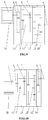
- a longitudinal multi-shift electrically driving power assembly which is particularly a longitudinal two-shift electrically driving power assembly that is added one front auxiliary gearbox.
- the power assembly comprises a power source 1 (the power source 1 is an electric motor), an electric-motor-and-transmission input integral shaft 2, a power-assembly output shaft 3, a front auxiliary gearbox 4, a two-shift gearbox 5, electromagnetic clutches 9, an electric-motor housing 11, a front housing 12, a middle housing 13 and a rear housing 14.
- the electric-motor shaft of the power source 1 and the input shaft of the front auxiliary gearbox 4 are integrated, which is the electric-motor-and-transmission input integral shaft 2.
- the output shaft of the front auxiliary gearbox 4 and the input shaft of the two-shift gearbox 5 are integrated, and the output shaft of the two-shift gearbox 5 serves as the output shaft of the entire power assembly.
- the front auxiliary gearbox 4 is a single-shift speed reducer.
- the two-shift gearbox 5 shifts gear by using two electromagnetic clutches 9.
- the electric-motor-and-transmission input integral shaft 2 and the power-assembly output shaft 3 are not coaxial and are in parallel, which is a non-coaxial electrically driving power assembly.
- the gears employed by the front auxiliary gearbox 4 and the two-shift gearbox 5 have a simple arrangement, a small room occupation, a compact structure and a light weight, which satisfies the trend of development of light weight and electrification.
- the transmission mode of the first embodiment of the present disclosure is as follows: When the electromagnetic clutch 9 between the integral shaft of the output of the front auxiliary gearbox 4 and the input of the two-shift gearbox 5 and the power-assembly output shaft 3 is engaged, and simultaneously the electromagnetic clutch 9 on the intermediate shaft of the two-shift gearbox 5 is disengaged, the power source 1 transmits the power via sequentially the electric-motor-and-transmission input integral shaft 2, a pair of gears of the front auxiliary gearbox 4 , the integral shaft of the output of the front auxiliary gearbox 4 and the input of the two-shift gearbox 5 to the power-assembly output shaft 3, in which case the longitudinal two-shift electrically driving power assembly is at the top gear. If it is set that the transmission ratio of the front auxiliary gearbox 4 is i1, and the transmission ratio of the two-shift gearbox 5 is i2, then the transmission ratio of the top gear of the longitudinal two-shift electrically driving power assembly is i1.
- the power source 1 transmits the power via sequentially the electric-motor-and-transmission input integral shaft 2, a pair of gears of the front auxiliary gearbox 4 , the integral shaft of the output of the front auxiliary gearbox 4 and the input of the two-shift gearbox 5 and two pairs of gears of the two-shift gearbox 5 to the power-assembly output shaft 3, in which case the longitudinal two-shift electrically driving power assembly is at the low gear. If it is set that the transmission ratio of the front auxiliary gearbox 4 is i1, and the transmission ratio of the two-shift gearbox 5 is i2, then the transmission ratio of the low gear of the longitudinal two-shift electrically driving power assembly is i1 ⁇ i2.
- the magnitudes of the transmission ratios of the two-shift gearbox 5 and the front auxiliary gearbox 4 may be changed by changing the sizes or the tooth numbers of the gears, thereby changing the transmission ratio of the longitudinal two-shift electrically driving power assembly.
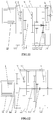
- FIG. 2 differs from Fig. 1 in that in Fig. 1 the electromagnetic clutch 9 employed by the intermediate shaft of the two-shift gearbox 5 is located between the two stages of gears, while in Fig. 2 the electromagnetic clutch 9 employed by the intermediate shaft of the two-shift gearbox 5 is located on the outside of one of the two stages of gears. Both of the two forms are feasible.
- a longitudinal multi-shift electrically driving power assembly which is particularly a longitudinal two-shift electrically driving power assembly that is added one rear auxiliary gearbox.
- the power assembly comprises a power source 1 (the power source 1 is an electric motor), an electric-motor-and-transmission input integral shaft 2, a power-assembly output shaft 3, a rear auxiliary gearbox 6, a two-shift gearbox 5, electromagnetic clutches 9, an electric-motor housing 11, a front housing 12, a middle housing 13 and a rear housing 14.
- the electric-motor shaft of the power source 1 and the input shaft of the two-shift gearbox 5 are integrated, which is the electric-motor-and-transmission input integral shaft 2.
- the output shaft of the two-shift gearbox 5 and the input shaft of the rear auxiliary gearbox 6 are integrated, and the output shaft of the rear auxiliary gearbox 6 serves as the output shaft of the entire power assembly.
- the two-shift gearbox 5 shifts gear by using two electromagnetic clutches 9.
- the rear auxiliary gearbox 6 is a single-shift speed reducer.
- the electric-motor-and-transmission input integral shaft 2 and the power-assembly output shaft 3 are not coaxial and are in parallel, which is a non-coaxial electrically driving power assembly.
- the gears employed by the two-shift gearbox 5 and the rear auxiliary gearbox 6 have a simple arrangement, a small room occupation, a compact structure and a light weight, which satisfies the trend of development of light weight and electrification.
- the transmission mode of the second embodiment of the present disclosure is as follows: When the electromagnetic clutch 9 between the electric-motor-and-transmission input integral shaft 2 and the integral shaft of the output of the two-shift gearbox 5 and the input of the rear auxiliary gearbox 6 is engaged, and simultaneously the electromagnetic clutch 9 on the intermediate shaft of the two-shift gearbox 5 is disengaged, the power source 1 transmits the power via sequentially the electric-motor-and-transmission input integral shaft 2, the integral shaft of the output of the two-shift gearbox 5 and the input of the rear auxiliary gearbox 6, and a pair of gears of the rear auxiliary gearbox 6 to the power-assembly output shaft 3, in which case the longitudinal two-shift electrically driving power assembly is at the top gear. If it is set that the transmission ratio of the two-shift gearbox 5 is i2, and the transmission ratio of the rear auxiliary gearbox 6 is i3, then the transmission ratio of the top gear of the longitudinal two-shift electrically driving power assembly is i3.
- the power source 1 transmits the power via sequentially the electric-motor-and-transmission input integral shaft 2, two pairs of gears of the two-shift gearbox 5 ,the integral shaft of the output of the two-shift gearbox 5 and the input of the rear auxiliary gearbox 6 and a pair of gears of the rear auxiliary gearbox 6 to the power-assembly output shaft 3, in which case the longitudinal two-shift electrically driving power assembly is at the low gear. If it is set that the transmission ratio of the two-shift gearbox 5 is i2, and the transmission ratio of the rear auxiliary gearbox 6 is i3, then the transmission ratio of the low gear of the longitudinal two-shift electrically driving power assembly is i2 ⁇ i3.
- a longitudinal multi-shift electrically driving power assembly which is particularly a longitudinal two-shift electrically driving power assembly that is added one front auxiliary gearbox and one rear auxiliary gearbox.
- the power assembly comprises a power source 1 (the power source 1 is an electric motor), an electric-motor-and-transmission input integral shaft 2, a power-assembly output shaft 3, a front auxiliary gearbox 4 , a rear auxiliary gearbox 6, a two-shift gearbox 5, electromagnetic clutches 9, an electric-motor housing 11, a front housing 12, a middle housing 13 and a rear housing 14.
- the electric-motor shaft of the power source 1 and the input shaft of the front auxiliary gearbox 4 are integrated, which is the electric-motor-and-transmission input integral shaft 2.
- the output shaft of the front auxiliary gearbox 4 and the input shaft of the two-shift gearbox 5 are integrated, the output shaft of the two-shift gearbox 5 and the input shaft of the rear auxiliary gearbox 6 are integrated, and the output shaft of the rear auxiliary gearbox 6 serves as the output shaft of the entire power assembly.
- the two-shift gearbox 5 shifts gear by using two electromagnetic clutches 9.
- Both of the front auxiliary gearbox 4 and the rear auxiliary gearbox 6 are a single-shift speed reducer.
- the electric-motor-and-transmission input integral shaft 2 and the power-assembly output shaft 3 are coaxial, which is a coaxial electrically driving power assembly.
- the gears employed by the two-shift gearbox 5, the front auxiliary gearbox 4 and the rear auxiliary gearbox 6 have a simple arrangement, a small room occupation, a compact structure and a light weight, which satisfies the trend of development of light weight and electrification.
- the transmission mode of the third embodiment of the present disclosure is as follows: When the electromagnetic clutch 9 between the integral shaft of the output of the front auxiliary gearbox 4 and the input of the two-shift gearbox 5 and the integral shaft of the output of the two-shift gearbox 5 and the input of the rear auxiliary gearbox 6 is engaged, and simultaneously the electromagnetic clutch 9 on the intermediate shaft of the two-shift gearbox 5 is disengaged, the power source 1 transmits the power via sequentially the electric-motor-and-transmission input integral shaft 2, a pair of gears of the front auxiliary gearbox 4 , the integral shaft of the output of the front auxiliary gearbox 4 and the input of the two-shift gearbox 5, the integral shaft of the output of the two-shift gearbox 5 and the input of the rear auxiliary gearbox 6, and a pair of gears of the rear auxiliary gearbox 6 to the power-assembly output shaft 3, in which case the longitudinal two-shift electrically driving power assembly is at the top gear.
- the transmission ratio of the front auxiliary gearbox 4 is i1
- the transmission ratio of the two-shift gearbox 5 is i2
- the transmission ratio of the rear auxiliary gearbox 6 is i3
- the transmission ratio of the top gear of the longitudinal two-shift electrically driving power assembly is i1 ⁇ i3.
- the power source 1 transmits the power via sequentially the electric-motor-and-transmission input integral shaft 2, a pair of gears of the front auxiliary gearbox 4 , the integral shaft of the output of the front auxiliary gearbox 4 and the input of the two-shift gearbox 5, two pairs of gears of the two-shift gearbox 5 , the integral shaft of the output of the two-shift gearbox 5 and the input of the rear auxiliary gearbox 6, and a pair of gears of the rear auxiliary gearbox 6 to the power-assembly output shaft 3, in which case the longitudinal two-shift electrically driving power assembly is at the low gear.
- the transmission ratio of the front auxiliary gearbox 4 is i1
- the transmission ratio of the two-shift gearbox 5 is i2
- the transmission ratio of the rear auxiliary gearbox 6 is i3
- the transmission ratio of the low gear of the longitudinal two-shift electrically driving power assembly is i1 ⁇ i2 ⁇ i3.
- a longitudinal multi-shift electrically driving power assembly which is particularly a longitudinal four-shift electrically driving power assembly.
- the power assembly comprises a power source 1 (the power source 1 is an electric motor), an electric-motor-and-transmission input integral shaft 2, a power-assembly output shaft 3, a double-intermediate-shaft four-shift gearbox 7, electromagnetic clutches 9, an electric-motor housing 11, a front housing 12, a middle housing 13 , a rear housing 14 and a bidirectional synchronizer 15.
- the electric-motor shaft of the power source 1 and the input shaft of the double-intermediate-shaft four-shift gearbox 7 are integrated, which is the electric-motor-and-transmission input integral shaft 2.
- the output shaft of the double-intermediate-shaft four-shift gearbox 7 serves as the output shaft of the entire power assembly.
- the double-intermediate-shaft four-shift gearbox 7 shifts gear by using two electromagnetic clutches 9 and one bidirectional synchronizer 15.
- the double-intermediate-shaft four-shift gearbox 7 is formed by one front two-shift gearbox 5 and one rear two-shift gearbox 5, and the output shaft of the front two-shift gearbox 5 and the input shaft of the rear two-shift gearbox 5 are integrated.
- the rear two-shift gearbox 5 has two intermediate shafts; in other words, the rear two-shift gearbox is a double-intermediate-shaft two-shift gearbox. Therefore, the entire four-shift gearbox is a double-intermediate-shaft four-shift gearbox.
- the transmission mode of the fourth embodiment of the present disclosure is as follows: When the electromagnetic clutch 9 between the electric-motor-and-transmission input integral shaft 2 and the integral shaft of the output of the front two-shift gearbox 5 and the input of the rear two-shift gearbox 5 is engaged, the integral shaft of the output of the front two-shift gearbox 5 and the input of the rear two-shift gearbox 5 is engaged with the power-assembly output shaft 3 by the action of the bidirectional synchronizer 15, and simultaneously the electromagnetic clutch 9 on the intermediate shaft of the front two-shift gearbox 5 is disengaged, the power source 1 transmits the power via sequentially the electric-motor-and-transmission input integral shaft 2 and the integral shaft of the output of the front two-shift gearbox 5 and the input of the rear two-shift gearbox 5 to the power-assembly output shaft 3 , in which case the longitudinal four-shift electrically driving power assembly is at the first gear, i.e., the directly linking gear. Then the transmission ratio of the first gear of the longitudinal four-shift electrically
- the electromagnetic clutch 9 between the electric-motor-and-transmission input integral shaft 2 and the integral shaft of the output of the front two-shift gearbox 5 and the input of the rear two-shift gearbox 5 is disengaged, the integral shaft of the output of the front two-shift gearbox 5 and the input of the rear two-shift gearbox 5 is engaged with the power-assembly output shaft 3 by the action of the bidirectional synchronizer 15, and simultaneously the electromagnetic clutch 9 on the intermediate shaft of the front two-shift gearbox 5 is engaged, the power source 1 transmits the power via sequentially the electric-motor-and-transmission input integral shaft 2, two pairs of gears of the front two-shift gearbox 5, and the integral shaft of the output of the front two-shift gearbox 5 and the input of the rear two-shift gearbox 5 to the power-assembly output shaft 3 , in which case the longitudinal four-shift electrically driving power assembly is at the third gear. If it is set that the transmission ratio of the front two-shift gearbox 5 is i4, and the transmission ratio of the rear two-
- the transmission ratio of the front two-shift gearbox 5 is i4, and the transmission ratio of the rear two-shift gearbox 5 is i5, then the transmission ratio of the fourth gear of the longitudinal four-shift electrically driving power assembly is i4 ⁇ i5.
- Fig. 6 shows another form of the fourth embodiment of the present disclosure.
- Fig. 6 differs from Fig. 5 in that Fig. 5 , on the basis of Fig. 6 , is added one intermediate shaft, which can increase the output torque and reduce the cost of the electric motor.
- Figs. 7 and 8 show another form of the fourth embodiment of the present disclosure.
- the four-shift gearbox in Figs. 7 and 8 employs three pairs of gears, which is less than those of the four-shift gearbox in Figs. 5 and 6 by one pair of gears.
- the electric-motor-and-transmission input integral shaft 2 and the power-assembly output shaft 3 are coaxial, which is a coaxial electrically driving power assembly.
- the electric-motor-and-transmission input integral shaft 2 and the power-assembly output shaft 3 are not coaxial and are in parallel, which is a non-coaxial electrically driving power assembly.
- a longitudinal multi-shift electrically driving power assembly which is particularly a longitudinal four-shift electrically driving power assembly that is added one front auxiliary gearbox.
- the fifth embodiment of the present disclosure is equivalent to changing, on the basis of the first embodiment, the two-shift gearbox into a four-shift gearbox, or is equivalent to adding, on the basis of the first embodiment, a rear two-shift auxiliary gearbox at the rear of the two-shift gearbox.
- the output shaft of the front auxiliary gearbox 4 and the input shaft of the double-intermediate-shaft four-shift gearbox 7 are integrated, and the output shaft of the double-intermediate-shaft four-shift gearbox 7 serves as the output shaft of the entire power assembly.
- the particular embodiment may refer to the first embodiment and the fourth embodiment.
- a longitudinal multi-shift electrically driving power assembly which is particularly a longitudinal four-shift electrically driving power assembly that is added one rear auxiliary gearbox.
- the sixth embodiment of the present disclosure is equivalent to changing, on the basis of the second embodiment, the two-shift gearbox into a four-shift gearbox, or is equivalent to adding, on the basis of the second embodiment, a front two-shift auxiliary gearbox in front of the two-shift gearbox.
- the output shaft of the double-intermediate-shaft four-shift gearbox 7 and the input shaft of the rear auxiliary gearbox 6 are integrated, and the output shaft of the rear auxiliary gearbox 6 serves as the output shaft of the entire power assembly.
- the particular embodiment may refer to the second embodiment and the fourth embodiment.
- a longitudinal multi-shift electrically driving power assembly which is particularly a longitudinal four-shift electrically driving power assembly that is added one front auxiliary gearbox and one rear auxiliary gearbox.
- the seventh embodiment of the present disclosure is equivalent to changing, on the basis of the third embodiment, the two-shift gearbox into a four-shift gearbox.
- the output shaft of the front auxiliary gearbox 4 and the input shaft of the double-intermediate-shaft four-shift gearbox 7 are integrated, the output shaft of the double-intermediate-shaft four-shift gearbox 7 and the input shaft of the rear auxiliary gearbox 6 are integrated, and the output shaft of the rear auxiliary gearbox 6 serves as the output shaft of the entire power assembly.
- the particular embodiment may refer to the third embodiment and the fourth embodiment.
- a longitudinal multi-shift electrically driving power assembly is disclosed, which is particularly a longitudinal eight-shift electrically driving power assembly.
- the eighth embodiment of the present disclosure is equivalent to adding, on the basis of the fourth embodiment, one rear two-shift auxiliary gearbox at the rear of the double-intermediate-shaft four-shift gearbox 7, or is equivalent to changing, on the basis of the third embodiment, the single-shift speed reducer serving as the front auxiliary gearbox and the rear auxiliary gearbox into a front two-shift auxiliary gearbox and a rear two-shift auxiliary gearbox.
- the particular embodiment may refer to the third embodiment and the fourth embodiment.
Landscapes
- Engineering & Computer Science (AREA)
- Mechanical Engineering (AREA)
- Chemical & Material Sciences (AREA)
- Combustion & Propulsion (AREA)
- Transportation (AREA)
- General Engineering & Computer Science (AREA)
- Structure Of Transmissions (AREA)
- Motor Power Transmission Devices (AREA)
- Hybrid Electric Vehicles (AREA)
Abstract
Description
- The present disclosure relates to a longitudinal multi-shift electrically driving power assembly, connected to the transmission shaft of a vehicle, for driving the vehicle.
- Currently, the power characteristics of the electric motors employed by purely electric or hybrid-power new-energy vehicles have gaps with the requirements of the entire vehicles, and cannot satisfy the requirements on the speed ratios and the moments. Because new-energy vehicles are required to handle increasingly more complicated working conditions and road conditions, and the users have raised increasingly more stringent demands on the comprehensive consideration on the maximum vehicle speed and the maximum gradeability of new-energy vehicles, new-energy vehicles that employ the power mode of purely direct driving by an electric motor have become incapable of satisfying the requirements of the industry of new-energy vehicles on the development of vehicles that have comprehensively taken into consideration the high power, the high torque and the maximum vehicle speed.
- All of the conventional vehicle power assemblies employ a single-shift transmission, whose output shaft is connected to a transmission shaft. Such a mode, in special cases, is restricted by the capacity of the electric motor, and cannot satisfy at the same time the requirements on high-torque and high-speed performance in conditions such as starting up and climbing.
- Aiming at the above problems in the prior art, the present disclosure provides a longitudinal multi-shift electrically driving power assembly, which employs a plurality of sets of gearboxes that are connected in series, which improves the performance of the power assembly.
- To achieve the above object, the technical solutions of the present disclosure are realized as follows:
The present disclosure provides a longitudinal multi-shift electrically driving power assembly, wherein the longitudinal multi-shift electrically driving power assembly comprises an electric motor and a plurality of sets of gearboxes, each of the gearboxes is a single-shift reduction gearbox or a multi-shift reduction gearbox, the gearboxes are connected in series to form a gearbox assembly, and an output shaft of the electric motor and an input shaft of the gearbox assembly are integrally manufactured. - Optionally, a gearbox that is adjacently connected to the electric motor is a single-shift reduction gearbox or a multi-shift reduction gearbox, the output shaft of the electric motor and an input shaft of the adjacent gearbox are integrally manufactured, and a rear cover of the electric motor and a front housing of the adjacent gearbox are integrally manufactured; and
when different gearboxes are adjacently connected, an output shaft of a gearbox in front and an input shaft of a gearbox at rear are integrally manufactured or are connected by a shaft coupling. - Optionally, the gearboxes are two sets of gearboxes, and include a single-shift reduction gearbox and a two-shift reduction gearbox that are sequentially connected; or
include a two-shift reduction gearbox and a single-shift reduction gearbox that are sequentially connected; or
include a front two-shift reduction gearbox and a rear two-shift reduction gearbox that are sequentially connected. - Optionally, the gearboxes are three sets of gearboxes, and include a front single-shift reduction gearbox, a two-shift reduction gearbox and a rear single-shift reduction gearbox that are sequentially connected; or
include a single-shift reduction gearbox, a middle two-shift reduction gearbox and a rear two-shift reduction gearbox that are sequentially connected; or
include a front two-gear reduction gearbox, a middle two-gear reduction gearbox and a single-shift reduction gearbox that are sequentially connected; or
include a front two-shift reduction gearbox, a middle two-shift reduction gearbox and a rear two-shift reduction gearbox that are sequentially connected. - Optionally, the gearboxes are four sets of gearboxes, and include a front single-shift reduction gearbox, a middle two-shift reduction gearbox, a rear two-shift reduction gearbox and a rear single-shift reduction gearbox that are sequentially connected.
- Optionally, an input shaft and an output shaft are provided in the single-shift reduction gearbox, and each of the input shaft and the output shaft is provided with an engaged transmission gear;
a transmission gear on the input shaft is fixedly connected to the input shaft or is idle-nested to the input shaft, and a transmission gear on the output shaft is fixedly connected to the output shaft or is idle-nested to the output shaft; and
a clutch is provided between the input shaft and the transmission gear idle-nested to the input shaft, and a clutch is provided between the output shaft and the transmission gear idle-nested to the output shaft. - Optionally, the input shaft and the output shaft of the gearbox assembly are coaxial, or are non-coaxial and in parallel.
- Optionally, the multi-shift reduction gearbox is a two-shift reduction gearbox, an input shaft, one or more intermediate shafts and an output shaft are provided in the two-shift reduction gearbox, each of the input shaft and the intermediate shaft is provided with an engaged transmission gear, each of the intermediate shaft and the output shaft is provided with an engaged transmission gear, the transmission gear on the intermediate shaft is fixedly connected to the intermediate shaft or is idle-nested to the intermediate shaft, and the transmission gear on the output shaft is fixedly connected to the output shaft or is idle-nested to the output shaft.
- Optionally, a clutch is provided between the input shaft and the output shaft, a clutch is provided between the intermediate shaft and the transmission gear idle-nested to the intermediate shaft, and the clutch on the intermediate shaft is located between two stages of gears, or is located on an outside of two stages of gears.
- Optionally, a bidirectional synchronizer is provided between the input shaft and the output shaft, the transmission gear on the output shaft is idle-nested to the output shaft, and the transmission gear on the intermediate shaft is fixedly connected to the intermediate shaft.
- The power assembly, by employing the above structure configuration, has the following advantages:
In the power assembly according to the present disclosure, without adding a power source, the quantity of the shifts of the transmission is increased, a single-shift speed reducer is added or an intermediate shaft is added, whereby the high-efficiency region of the electric motor is better utilized, thereby improving the power performance of the vehicle, reducing the requirement on the maximum torque of the electric motor, reducing the size of the electric motor, and reducing the cost of the electric motor. - The power assembly according to the present disclosure is connected to the rear axle half shaft or the front axle half shaft of the vehicle, can realize transmissions of multiple speed ratios, and has flexible transmission modes and power input modes, which satisfies the demands of the entire vehicle on travelling on different road conditions. When the vehicle is climbing while burdened with a weight, the double-power output and the transmission of the larger speed ratio may be selected, to increase the driving force of the entire vehicle, to overcome the defect of the insufficient driving force of the entire vehicle. When the entire vehicle is in the cruising state, the single power input and the transmission of the smaller speed ratio may be selected, to satisfy the requirement on the high-speed travelling of the entire vehicle, save energy, and increase the endurance mileage of the vehicle.
-
-
Fig. 1 is a schematic structural diagram of the longitudinal multi-shift electrically driving power assembly with one two-shift gearbox plus one front auxiliary gearbox according to the first embodiment of the present disclosure (wherein the clutch is between the two stages of gears of the two-shift gearbox); -
Fig. 2 is a schematic structural diagram of the longitudinal multi-shift electrically driving power assembly with one two-shift gearbox plus one front auxiliary gearbox according to the first embodiment of the present disclosure (wherein the clutch is on the outside of the two stages of gears of the two-shift gearbox); -
Fig. 3 is a schematic structural diagram of the longitudinal multi-shift electrically driving power assembly with one two-shift gearbox plus one rear auxiliary gearbox according to the second embodiment of the present disclosure; -
Fig. 4 is a schematic structural diagram of the longitudinal multi-shift electrically driving power assembly with one two-shift gearbox plus one front auxiliary gearbox and one rear auxiliary gearbox according to the third embodiment of the present disclosure; -
Fig. 5 is a schematic structural diagram of the longitudinal multi-shift electrically driving power assembly with a four-shift gearbox according to the fourth embodiment of the present disclosure (four pairs of gears, wherein the rear two-shift gearbox has double intermediate shafts); -
Fig. 6 is a schematic structural diagram of the longitudinal multi-shift electrically driving power assembly with a four-shift gearbox according to the fourth embodiment of the present disclosure (four pairs of gears, and a single intermediate shaft); -
Fig. 7 is a schematic structural diagram of the longitudinal multi-shift electrically driving power assembly with a four-shift gearbox according to the fourth embodiment of the present disclosure (three pair of gears, wherein the input shaft and the output shaft of the gearbox assembly are driven coaxially); -
Fig. 8 is a schematic structural diagram of the longitudinal multi-shift electrically driving power assembly with a four-shift gearbox according to the fourth embodiment of the present disclosure (three pair of gears, wherein the input shaft and the output shaft of the gearbox assembly are driven non-coaxially); -
Fig. 9 is a schematic structural diagram of the longitudinal multi-shift electrically driving power assembly with one four-shift gearbox plus one front auxiliary gearbox according to the fifth embodiment of the present disclosure (wherein the rear two-shift gearbox has double intermediate shafts); -
Fig. 10 is a schematic structural diagram of the longitudinal multi-shift electrically driving power assembly with one four-shift gearbox plus one rear auxiliary gearbox according to the sixth embodiment of the present disclosure (wherein the middle two-shift gearbox has double intermediate shafts); -
Fig. 11 is a schematic structural diagram of the longitudinal multi-shift electrically driving power assembly with one four-shift gearbox plus one front auxiliary gearbox and one rear auxiliary gearbox according to the seventh embodiment of the present disclosure (wherein the rear two-shift gearbox has double intermediate shafts); and -
Fig. 12 is a schematic structural diagram of the longitudinal multi-shift electrically driving power assembly with an eight-shift gearbox according to the eighth embodiment of the present disclosure (wherein the middle two-shift gearbox has double intermediate shafts). - In the drawings: 1. power source; 2. electric-motor-and-transmission input integral shaft; 3. power-assembly output shaft; 4. front auxiliary gearbox; 5. two-shift gearbox; 6. rear auxiliary gearbox; 7. double-intermediate-shaft four-shift gearbox; 8. single-intermediate-shaft four-shift gearbox; 9. electromagnetic clutches; 10. eight-shift gearbox; 11. electric-motor housing; 12. front housing; 13. middle housing; 14. rear housing; and 15. bidirectional synchronizer.
- In order to make the objects, the technical solutions and the advantages of the present disclosure clearer, the embodiments of the present disclosure will be described below in further detail in conjunction with the drawings.
- As shown in
Fig. 1 , in the first embodiment of the present disclosure, a longitudinal multi-shift electrically driving power assembly is disclosed, which is particularly a longitudinal two-shift electrically driving power assembly that is added one front auxiliary gearbox. The power assembly comprises a power source 1 (the power source 1 is an electric motor), an electric-motor-and-transmission input integral shaft 2, a power-assembly output shaft 3, a front auxiliary gearbox 4, a two-shift gearbox 5,electromagnetic clutches 9, an electric-motor housing 11, afront housing 12, amiddle housing 13 and arear housing 14. - The electric-motor shaft of the power source 1 and the input shaft of the front auxiliary gearbox 4 are integrated, which is the electric-motor-and-transmission input integral shaft 2. The output shaft of the front auxiliary gearbox 4 and the input shaft of the two-
shift gearbox 5 are integrated, and the output shaft of the two-shift gearbox 5 serves as the output shaft of the entire power assembly. The front auxiliary gearbox 4 is a single-shift speed reducer. The two-shift gearbox 5 shifts gear by using twoelectromagnetic clutches 9. The electric-motor-and-transmission input integral shaft 2 and the power-assembly output shaft 3 are not coaxial and are in parallel, which is a non-coaxial electrically driving power assembly. The gears employed by the front auxiliary gearbox 4 and the two-shift gearbox 5 have a simple arrangement, a small room occupation, a compact structure and a light weight, which satisfies the trend of development of light weight and electrification. - The transmission mode of the first embodiment of the present disclosure is as follows:
When theelectromagnetic clutch 9 between the integral shaft of the output of the front auxiliary gearbox 4 and the input of the two-shift gearbox 5 and the power-assembly output shaft 3 is engaged, and simultaneously theelectromagnetic clutch 9 on the intermediate shaft of the two-shift gearbox 5 is disengaged, the power source 1 transmits the power via sequentially the electric-motor-and-transmission input integral shaft 2, a pair of gears of the front auxiliary gearbox 4 , the integral shaft of the output of the front auxiliary gearbox 4 and the input of the two-shift gearbox 5 to the power-assembly output shaft 3, in which case the longitudinal two-shift electrically driving power assembly is at the top gear. If it is set that the transmission ratio of the front auxiliary gearbox 4 is i1, and the transmission ratio of the two-shift gearbox 5 is i2, then the transmission ratio of the top gear of the longitudinal two-shift electrically driving power assembly is i1. - When the
electromagnetic clutch 9 between the integral shaft of the output of the front auxiliary gearbox 4 and the input of the two-shift gearbox 5 and the power-assembly output shaft 3 is disengaged, and simultaneously theelectromagnetic clutch 9 on the intermediate shaft of the two-shift gearbox 5 is engaged, the power source 1 transmits the power via sequentially the electric-motor-and-transmission input integral shaft 2, a pair of gears of the front auxiliary gearbox 4 , the integral shaft of the output of the front auxiliary gearbox 4 and the input of the two-shift gearbox 5 and two pairs of gears of the two-shift gearbox 5 to the power-assembly output shaft 3, in which case the longitudinal two-shift electrically driving power assembly is at the low gear. If it is set that the transmission ratio of the front auxiliary gearbox 4 is i1, and the transmission ratio of the two-shift gearbox 5 is i2, then the transmission ratio of the low gear of the longitudinal two-shift electrically driving power assembly is i1×i2. - The magnitudes of the transmission ratios of the two-
shift gearbox 5 and the front auxiliary gearbox 4 may be changed by changing the sizes or the tooth numbers of the gears, thereby changing the transmission ratio of the longitudinal two-shift electrically driving power assembly. - In addition, another form of the first embodiment of the present disclosure is shown in
Fig. 2. Fig. 2 differs fromFig. 1 in that inFig. 1 theelectromagnetic clutch 9 employed by the intermediate shaft of the two-shift gearbox 5 is located between the two stages of gears, while inFig. 2 theelectromagnetic clutch 9 employed by the intermediate shaft of the two-shift gearbox 5 is located on the outside of one of the two stages of gears. Both of the two forms are feasible. - As shown in
Fig. 3 , in the second embodiment of the present disclosure, a longitudinal multi-shift electrically driving power assembly is disclosed, which is particularly a longitudinal two-shift electrically driving power assembly that is added one rear auxiliary gearbox. The power assembly comprises a power source 1 (the power source 1 is an electric motor), an electric-motor-and-transmission input integral shaft 2, a power-assembly output shaft 3, a rear auxiliary gearbox 6, a two-shift gearbox 5,electromagnetic clutches 9, an electric-motor housing 11, afront housing 12, amiddle housing 13 and arear housing 14. - The electric-motor shaft of the power source 1 and the input shaft of the two-
shift gearbox 5 are integrated, which is the electric-motor-and-transmission input integral shaft 2. The output shaft of the two-shift gearbox 5 and the input shaft of the rear auxiliary gearbox 6 are integrated, and the output shaft of the rear auxiliary gearbox 6 serves as the output shaft of the entire power assembly. The two-shift gearbox 5 shifts gear by using twoelectromagnetic clutches 9. The rear auxiliary gearbox 6 is a single-shift speed reducer. The electric-motor-and-transmission input integral shaft 2 and the power-assembly output shaft 3 are not coaxial and are in parallel, which is a non-coaxial electrically driving power assembly. The gears employed by the two-shift gearbox 5 and the rear auxiliary gearbox 6 have a simple arrangement, a small room occupation, a compact structure and a light weight, which satisfies the trend of development of light weight and electrification. - The transmission mode of the second embodiment of the present disclosure is as follows:
When theelectromagnetic clutch 9 between the electric-motor-and-transmission input integral shaft 2 and the integral shaft of the output of the two-shift gearbox 5 and the input of the rear auxiliary gearbox 6 is engaged, and simultaneously theelectromagnetic clutch 9 on the intermediate shaft of the two-shift gearbox 5 is disengaged, the power source 1 transmits the power via sequentially the electric-motor-and-transmission input integral shaft 2, the integral shaft of the output of the two-shift gearbox 5 and the input of the rear auxiliary gearbox 6, and a pair of gears of the rear auxiliary gearbox 6 to the power-assembly output shaft 3, in which case the longitudinal two-shift electrically driving power assembly is at the top gear. If it is set that the transmission ratio of the two-shift gearbox 5 is i2, and the transmission ratio of the rear auxiliary gearbox 6 is i3, then the transmission ratio of the top gear of the longitudinal two-shift electrically driving power assembly is i3. - When the
electromagnetic clutch 9 between the electric-motor-and-transmission input integral shaft 2 and the integral shaft of the output of the two-shift gearbox 5 and the input of the rear auxiliary gearbox 6 is disengaged, and simultaneously theelectromagnetic clutch 9 on the intermediate shaft of the two-shift gearbox 5 is engaged, the power source 1 transmits the power via sequentially the electric-motor-and-transmission input integral shaft 2, two pairs of gears of the two-shift gearbox 5 ,the integral shaft of the output of the two-shift gearbox 5 and the input of the rear auxiliary gearbox 6 and a pair of gears of the rear auxiliary gearbox 6 to the power-assembly output shaft 3, in which case the longitudinal two-shift electrically driving power assembly is at the low gear. If it is set that the transmission ratio of the two-shift gearbox 5 is i2, and the transmission ratio of the rear auxiliary gearbox 6 is i3, then the transmission ratio of the low gear of the longitudinal two-shift electrically driving power assembly is i2×i3. - The other contents of the second embodiment of the present disclosure are the same as those of the first embodiment, and are not described repeatedly here.
- As shown in
Fig. 4 , in the third embodiment of the present disclosure, a longitudinal multi-shift electrically driving power assembly is disclosed, which is particularly a longitudinal two-shift electrically driving power assembly that is added one front auxiliary gearbox and one rear auxiliary gearbox. The power assembly comprises a power source 1 (the power source 1 is an electric motor), an electric-motor-and-transmission input integral shaft 2, a power-assembly output shaft 3, a front auxiliary gearbox 4 , a rear auxiliary gearbox 6, a two-shift gearbox 5,electromagnetic clutches 9, an electric-motor housing 11, afront housing 12, amiddle housing 13 and arear housing 14. - The electric-motor shaft of the power source 1 and the input shaft of the front auxiliary gearbox 4 are integrated, which is the electric-motor-and-transmission input integral shaft 2. The output shaft of the front auxiliary gearbox 4 and the input shaft of the two-
shift gearbox 5 are integrated, the output shaft of the two-shift gearbox 5 and the input shaft of the rear auxiliary gearbox 6 are integrated, and the output shaft of the rear auxiliary gearbox 6 serves as the output shaft of the entire power assembly. The two-shift gearbox 5 shifts gear by using twoelectromagnetic clutches 9. Both of the front auxiliary gearbox 4 and the rear auxiliary gearbox 6 are a single-shift speed reducer. The electric-motor-and-transmission input integral shaft 2 and the power-assembly output shaft 3 are coaxial, which is a coaxial electrically driving power assembly. The gears employed by the two-shift gearbox 5, the front auxiliary gearbox 4 and the rear auxiliary gearbox 6 have a simple arrangement, a small room occupation, a compact structure and a light weight, which satisfies the trend of development of light weight and electrification. - The transmission mode of the third embodiment of the present disclosure is as follows:
When theelectromagnetic clutch 9 between the integral shaft of the output of the front auxiliary gearbox 4 and the input of the two-shift gearbox 5 and the integral shaft of the output of the two-shift gearbox 5 and the input of the rear auxiliary gearbox 6 is engaged, and simultaneously theelectromagnetic clutch 9 on the intermediate shaft of the two-shift gearbox 5 is disengaged, the power source 1 transmits the power via sequentially the electric-motor-and-transmission input integral shaft 2, a pair of gears of the front auxiliary gearbox 4 , the integral shaft of the output of the front auxiliary gearbox 4 and the input of the two-shift gearbox 5, the integral shaft of the output of the two-shift gearbox 5 and the input of the rear auxiliary gearbox 6, and a pair of gears of the rear auxiliary gearbox 6 to the power-assembly output shaft 3, in which case the longitudinal two-shift electrically driving power assembly is at the top gear. If it is set that the transmission ratio of the front auxiliary gearbox 4 is i1, the transmission ratio of the two-shift gearbox 5 is i2, and the transmission ratio of the rear auxiliary gearbox 6 is i3, then the transmission ratio of the top gear of the longitudinal two-shift electrically driving power assembly is i1×i3. - When the
electromagnetic clutch 9 between the integral shaft of the output of the front auxiliary gearbox 4 and the input of the two-shift gearbox 5 and the integral shaft of the output of the two-shift gearbox 5 and the input of the rear auxiliary gearbox 6 is disengaged, and simultaneously theelectromagnetic clutch 9 on the intermediate shaft of the two-shift gearbox 5 is engaged, the power source 1 transmits the power via sequentially the electric-motor-and-transmission input integral shaft 2, a pair of gears of the front auxiliary gearbox 4 , the integral shaft of the output of the front auxiliary gearbox 4 and the input of the two-shift gearbox 5, two pairs of gears of the two-shift gearbox 5 , the integral shaft of the output of the two-shift gearbox 5 and the input of the rear auxiliary gearbox 6, and a pair of gears of the rear auxiliary gearbox 6 to the power-assembly output shaft 3, in which case the longitudinal two-shift electrically driving power assembly is at the low gear. If it is set that the transmission ratio of the front auxiliary gearbox 4 is i1, the transmission ratio of the two-shift gearbox 5 is i2, and the transmission ratio of the rear auxiliary gearbox 6 is i3, then the transmission ratio of the low gear of the longitudinal two-shift electrically driving power assembly is i1×i2×i3. - The other contents of the third embodiment of the present disclosure are the same as those of the first embodiment, and are not described repeatedly here.
- As shown in
Fig. 5 , in the fourth embodiment of the present disclosure, a longitudinal multi-shift electrically driving power assembly is disclosed, which is particularly a longitudinal four-shift electrically driving power assembly. The power assembly comprises a power source 1 (the power source 1 is an electric motor), an electric-motor-and-transmission input integral shaft 2, a power-assembly output shaft 3, a double-intermediate-shaft four-shift gearbox 7,electromagnetic clutches 9, an electric-motor housing 11, afront housing 12, amiddle housing 13 , arear housing 14 and abidirectional synchronizer 15. - The electric-motor shaft of the power source 1 and the input shaft of the double-intermediate-shaft four-
shift gearbox 7 are integrated, which is the electric-motor-and-transmission input integral shaft 2. The output shaft of the double-intermediate-shaft four-shift gearbox 7 serves as the output shaft of the entire power assembly. The double-intermediate-shaft four-shift gearbox 7 shifts gear by using twoelectromagnetic clutches 9 and onebidirectional synchronizer 15. The double-intermediate-shaft four-shift gearbox 7 is formed by one front two-shift gearbox 5 and one rear two-shift gearbox 5, and the output shaft of the front two-shift gearbox 5 and the input shaft of the rear two-shift gearbox 5 are integrated. The rear two-shift gearbox 5 has two intermediate shafts; in other words, the rear two-shift gearbox is a double-intermediate-shaft two-shift gearbox. Therefore, the entire four-shift gearbox is a double-intermediate-shaft four-shift gearbox. - The transmission mode of the fourth embodiment of the present disclosure is as follows:
When theelectromagnetic clutch 9 between the electric-motor-and-transmission input integral shaft 2 and the integral shaft of the output of the front two-shift gearbox 5 and the input of the rear two-shift gearbox 5 is engaged, the integral shaft of the output of the front two-shift gearbox 5 and the input of the rear two-shift gearbox 5 is engaged with the power-assembly output shaft 3 by the action of thebidirectional synchronizer 15, and simultaneously theelectromagnetic clutch 9 on the intermediate shaft of the front two-shift gearbox 5 is disengaged, the power source 1 transmits the power via sequentially the electric-motor-and-transmission input integral shaft 2 and the integral shaft of the output of the front two-shift gearbox 5 and the input of the rear two-shift gearbox 5 to the power-assembly output shaft 3 , in which case the longitudinal four-shift electrically driving power assembly is at the first gear, i.e., the directly linking gear. Then the transmission ratio of the first gear of the longitudinal four-shift electrically driving power assembly is 1. - When the
electromagnetic clutch 9 between the electric-motor-and-transmission input integral shaft 2 and the integral shaft of the output of the front two-shift gearbox 5 and the input of the rear two-shift gearbox 5 is engaged, a second-stage gearwheel of the two-shift gearbox 5 is engaged with the power-assembly output shaft 3 by the action of thebidirectional synchronizer 15, and simultaneously theelectromagnetic clutch 9 on the intermediate shaft of the front two-shift gearbox 5 is disengaged, the power source 1 transmits the power via sequentially the electric-motor-and-transmission input integral shaft 2, the integral shaft of the output of the front two-shift gearbox 5 and the input of the rear two-shift gearbox 5 and two pairs of gears of the rear two-shift gearbox 5 to the power-assembly output shaft 3 , in which case the longitudinal four-shift electrically driving power assembly is at the second gear. If it is set that the transmission ratio of the front two-shift gearbox 5 is i4, and the transmission ratio of the rear two-shift gearbox 5 is i5, then the transmission ratio of the second gear of the longitudinal four-shift electrically driving power assembly is i5. - When the
electromagnetic clutch 9 between the electric-motor-and-transmission input integral shaft 2 and the integral shaft of the output of the front two-shift gearbox 5 and the input of the rear two-shift gearbox 5 is disengaged, the integral shaft of the output of the front two-shift gearbox 5 and the input of the rear two-shift gearbox 5 is engaged with the power-assembly output shaft 3 by the action of thebidirectional synchronizer 15, and simultaneously theelectromagnetic clutch 9 on the intermediate shaft of the front two-shift gearbox 5 is engaged, the power source 1 transmits the power via sequentially the electric-motor-and-transmission input integral shaft 2, two pairs of gears of the front two-shift gearbox 5, and the integral shaft of the output of the front two-shift gearbox 5 and the input of the rear two-shift gearbox 5 to the power-assembly output shaft 3 , in which case the longitudinal four-shift electrically driving power assembly is at the third gear. If it is set that the transmission ratio of the front two-shift gearbox 5 is i4, and the transmission ratio of the rear two-shift gearbox 5 is i5, then the transmission ratio of the third gear of the longitudinal four-shift electrically driving power assembly is i4. - When the
electromagnetic clutch 9 between the electric-motor-and-transmission input integral shaft 2 and the integral shaft of the output of the front two-shift gearbox 5 and the input of the rear two-shift gearbox 5 is disengaged, a second-stage gearwheel of the two-shift gearbox 5 is engaged with the power-assembly output shaft 3 by the action of thebidirectional synchronizer 15, and simultaneously theelectromagnetic clutch 9 on the intermediate shaft of the front two-shift gearbox 5 is engaged, the power source 1 transmits the power via sequentially the electric-motor-and-transmission input integral shaft 2, two pairs of gears of the front two-shift gearbox 5, the integral shaft of the output of the front two-shift gearbox 5 and the input of the rear two-shift gearbox 5, and two pairs of gears of the rear two-shift gearbox 5 to the power-assembly output shaft 3 , in which case the longitudinal four-shift electrically driving power assembly is at the fourth gear. If it is set that the transmission ratio of the front two-shift gearbox 5 is i4, and the transmission ratio of the rear two-shift gearbox 5 is i5, then the transmission ratio of the fourth gear of the longitudinal four-shift electrically driving power assembly is i4×i5. -
Fig. 6 shows another form of the fourth embodiment of the present disclosure.Fig. 6 differs fromFig. 5 in thatFig. 5 , on the basis ofFig. 6 , is added one intermediate shaft, which can increase the output torque and reduce the cost of the electric motor. -
Figs. 7 and 8 show another form of the fourth embodiment of the present disclosure. The four-shift gearbox inFigs. 7 and 8 employs three pairs of gears, which is less than those of the four-shift gearbox inFigs. 5 and 6 by one pair of gears. InFig. 7 the electric-motor-and-transmission input integral shaft 2 and the power-assembly output shaft 3 are coaxial, which is a coaxial electrically driving power assembly. InFig. 8 the electric-motor-and-transmission input integral shaft 2 and the power-assembly output shaft 3 are not coaxial and are in parallel, which is a non-coaxial electrically driving power assembly. - The other contents of the fourth embodiment of the present disclosure are the same as those of the first embodiment, and are not described repeatedly here.
- As shown in
Fig. 9 , in the fifth embodiment of the present disclosure, a longitudinal multi-shift electrically driving power assembly is disclosed, which is particularly a longitudinal four-shift electrically driving power assembly that is added one front auxiliary gearbox. The fifth embodiment of the present disclosure is equivalent to changing, on the basis of the first embodiment, the two-shift gearbox into a four-shift gearbox, or is equivalent to adding, on the basis of the first embodiment, a rear two-shift auxiliary gearbox at the rear of the two-shift gearbox. The output shaft of the front auxiliary gearbox 4 and the input shaft of the double-intermediate-shaft four-shift gearbox 7 are integrated, and the output shaft of the double-intermediate-shaft four-shift gearbox 7 serves as the output shaft of the entire power assembly. The particular embodiment may refer to the first embodiment and the fourth embodiment. - As shown in
Fig. 10 , in the sixth embodiment of the present disclosure, a longitudinal multi-shift electrically driving power assembly is disclosed, which is particularly a longitudinal four-shift electrically driving power assembly that is added one rear auxiliary gearbox. The sixth embodiment of the present disclosure is equivalent to changing, on the basis of the second embodiment, the two-shift gearbox into a four-shift gearbox, or is equivalent to adding, on the basis of the second embodiment, a front two-shift auxiliary gearbox in front of the two-shift gearbox. The output shaft of the double-intermediate-shaft four-shift gearbox 7 and the input shaft of the rear auxiliary gearbox 6 are integrated, and the output shaft of the rear auxiliary gearbox 6 serves as the output shaft of the entire power assembly. The particular embodiment may refer to the second embodiment and the fourth embodiment. - As shown in
Fig. 11 , in the seventh embodiment of the present disclosure, a longitudinal multi-shift electrically driving power assembly is disclosed, which is particularly a longitudinal four-shift electrically driving power assembly that is added one front auxiliary gearbox and one rear auxiliary gearbox. The seventh embodiment of the present disclosure is equivalent to changing, on the basis of the third embodiment, the two-shift gearbox into a four-shift gearbox. The output shaft of the front auxiliary gearbox 4 and the input shaft of the double-intermediate-shaft four-shift gearbox 7 are integrated, the output shaft of the double-intermediate-shaft four-shift gearbox 7 and the input shaft of the rear auxiliary gearbox 6 are integrated, and the output shaft of the rear auxiliary gearbox 6 serves as the output shaft of the entire power assembly. The particular embodiment may refer to the third embodiment and the fourth embodiment. - As shown in
Fig. 12 , in the eighth embodiment of the present disclosure, a longitudinal multi-shift electrically driving power assembly is disclosed, which is particularly a longitudinal eight-shift electrically driving power assembly. The eighth embodiment of the present disclosure is equivalent to adding, on the basis of the fourth embodiment, one rear two-shift auxiliary gearbox at the rear of the double-intermediate-shaft four-shift gearbox 7, or is equivalent to changing, on the basis of the third embodiment, the single-shift speed reducer serving as the front auxiliary gearbox and the rear auxiliary gearbox into a front two-shift auxiliary gearbox and a rear two-shift auxiliary gearbox. The particular embodiment may refer to the third embodiment and the fourth embodiment. - The above are merely particular embodiments of the present disclosure. By the teaching of the present disclosure, a person skilled in the art can make other modifications or variations on the basis of the above embodiments. A person skilled in the art should understand that the above particular descriptions are only for the purpose of better interpreting the present disclosure, and the protection scope of the present disclosure should be subject to the protection scope of the claims.
Claims (10)
- A longitudinal multi-shift electrically driving power assembly, characterized in that: the longitudinal multi-shift electrically driving power assembly comprises an electric motor and a plurality of sets of gearboxes, each of the gearboxes is a single-shift reduction gearbox or a multi-shift reduction gearbox, the gearboxes are connected in series to form a gearbox assembly, and an output shaft of the electric motor and an input shaft of the gearbox assembly are integrally manufactured.
- The longitudinal multi-shift electrically driving power assembly according to claim 1, characterized in that: a gearbox that is adjacently connected to the electric motor is a single-shift reduction gearbox or a multi-shift reduction gearbox, the output shaft of the electric motor and an input shaft of the adjacent gearbox are integrally manufactured, and a rear cover of the electric motor and a front housing (12) of the adjacent gearbox are integrally manufactured; and
when different gearboxes are adjacently connected, an output shaft of a gearbox in front and an input shaft of a gearbox at rear are integrally manufactured or are connected by a shaft coupling. - The longitudinal multi-shift electrically driving power assembly according to claim 1, characterized in that: the gearboxes are two sets of gearboxes, and include a single-shift reduction gearbox and a two-shift reduction gearbox that are sequentially connected; or
include a two-shift reduction gearbox and a single-shift reduction gearbox that are sequentially connected; or
include a front two-shift reduction gearbox and a rear two-shift reduction gearbox that are sequentially connected. - The longitudinal multi-shift electrically driving power assembly according to claim 1, characterized in that: the gearboxes are three sets of gearboxes, and include a front single-shift reduction gearbox, a two-shift reduction gearbox and a rear single-shift reduction gearbox that are sequentially connected; or
include a single-shift reduction gearbox, a middle two-shift reduction gearbox and a rear two-shift reduction gearbox that are sequentially connected; or
include a front two-shift reduction gearbox, a middle two-shift reduction gearbox and a single-shift reduction gearbox that are sequentially connected; or
include a front two-shift reduction gearbox, a middle two-shift reduction gearbox and a rear two-shift reduction gearbox that are sequentially connected. - The longitudinal multi-shift electrically driving power assembly according to claim 1, characterized in that: the gearboxes are four sets of gearboxes, and include a front single-shift reduction gearbox, a middle two-shift reduction gearbox, a rear two-shift reduction gearbox and a rear single-shift reduction gearbox that are sequentially connected.
- The longitudinal multi-shift electrically driving power assembly according to claim 1, characterized in that: an input shaft and an output shaft are provided in the single-shift reduction gearbox, and each of the input shaft and the output shaft is provided with an engaged transmission gear;
the transmission gear on the input shaft is fixedly connected to the input shaft or is idle-nested to the input shaft, and the transmission gear on the output shaft is fixedly connected to the output shaft or is idle-nested to the output shaft; and
a clutch is provided between the input shaft and the transmission gear idle-nested to the input shaft, and a clutch is provided between the output shaft and the transmission gear idle-nested to the output shaft. - The longitudinal multi-shift electrically driving power assembly according to claim 1, characterized in that: the input shaft and an output shaft of the gearbox assembly are coaxial, or are non-coaxial and in parallel.
- The longitudinal multi-shift electrically driving power assembly according to claim 1, characterized in that: the multi-shift reduction gearbox is a two-shift reduction gearbox, an input shaft, one or more intermediate shafts and an output shaft are provided in the two-shift reduction gearbox, each of the input shaft and the intermediate shaft is provided with an engaged transmission gear, each of the intermediate shaft and the output shaft is provided with an engaged transmission gear, the transmission gear on the intermediate shaft is fixedly connected to the intermediate shaft or is idle-nested to the intermediate shaft, and the transmission gear on the output shaft is fixedly connected to the output shaft or is idle-nested to the output shaft.
- The longitudinal multi-shift electrically driving power assembly according to claim 8, characterized in that: a clutch is provided between the input shaft and the output shaft, a clutch is provided between the intermediate shaft and the transmission gear idle-nested to the intermediate shaft, and the clutch on the intermediate shaft are located between two stages of gears, or are located on an outside of two stages of gears.
- The longitudinal multi-shift electrically driving power assembly according to claim 8, characterized in that: a bidirectional synchronizer (15) is provided between the input shaft and the output shaft, a transmission gear on the output shaft is idle-nested to the output shaft, and a transmission gear on the intermediate shaft is fixedly connected to the intermediate shaft.
Applications Claiming Priority (2)
| Application Number | Priority Date | Filing Date | Title |
|---|---|---|---|
| CN201810581680.9A CN108528185B (en) | 2018-06-07 | 2018-06-07 | A longitudinally mounted multi-gear electric drive powertrain |
| PCT/CN2019/089019 WO2019233329A1 (en) | 2018-06-07 | 2019-05-29 | Electric drive powertrain having vertically-positioned multi-stage gearboxes |
Publications (3)
| Publication Number | Publication Date |
|---|---|
| EP3778283A1 true EP3778283A1 (en) | 2021-02-17 |
| EP3778283A4 EP3778283A4 (en) | 2021-05-12 |
| EP3778283B1 EP3778283B1 (en) | 2023-10-11 |
Family
ID=63470351
Family Applications (1)
| Application Number | Title | Priority Date | Filing Date |
|---|---|---|---|
| EP19815195.3A Active EP3778283B1 (en) | 2018-06-07 | 2019-05-29 | Longitudinal multi-stage electrically driving power assembly |
Country Status (5)
| Country | Link |
|---|---|
| US (1) | US11623511B2 (en) |
| EP (1) | EP3778283B1 (en) |
| JP (1) | JP7380972B2 (en) |
| CN (1) | CN108528185B (en) |
| WO (1) | WO2019233329A1 (en) |
Cited By (1)
| Publication number | Priority date | Publication date | Assignee | Title |
|---|---|---|---|---|
| EP4209693A1 (en) * | 2022-01-11 | 2023-07-12 | Li-Ho Yao | Three-stage speed-change mechanism |
Families Citing this family (10)
| Publication number | Priority date | Publication date | Assignee | Title |
|---|---|---|---|---|
| CN108528185B (en) * | 2018-06-07 | 2024-01-19 | 精进电动科技股份有限公司 | A longitudinally mounted multi-gear electric drive powertrain |
| US11618281B2 (en) * | 2020-06-15 | 2023-04-04 | Arvinmeritor Technology, Llc | Axle assembly |
| CN112356647B (en) * | 2020-11-10 | 2022-04-08 | 浙江吉利控股集团有限公司 | Multi-motor flexible torque centralized driving synthesis box and electric vehicle |
| US11888377B2 (en) | 2021-03-30 | 2024-01-30 | Arvinmeritor Technology, Llc | Axle assembly having an electric motor module |
| US11685253B2 (en) | 2021-06-15 | 2023-06-27 | Arvinmeritor Technology, Llc | Drive axle system |
| CN116533732B (en) * | 2023-06-19 | 2026-02-27 | 东风德纳车桥有限公司 | A multi-speed electric drive axle drive structure and vehicle |
| CN116733939A (en) * | 2023-07-25 | 2023-09-12 | 东风商用车有限公司 | A gearbox and automobile |
| US12589644B2 (en) | 2023-12-19 | 2026-03-31 | Arvinmeritor Technology, Llc | Drive axle system having an electric motor |
| CN118564623A (en) * | 2024-05-31 | 2024-08-30 | 江苏大象机械有限公司 | Constant-power speed reducer set based on motor adjustment of electric slurry pump and assembling method thereof |
| CN120608947B (en) * | 2025-08-07 | 2025-10-17 | 天津津岛船务有限公司 | A limited protection type constant tension winch transmission gearbox |
Family Cites Families (34)
| Publication number | Priority date | Publication date | Assignee | Title |
|---|---|---|---|---|
| US5404772A (en) | 1992-11-06 | 1995-04-11 | Dana Corporation | Transmission housing |
| JP3584106B2 (en) * | 1996-01-26 | 2004-11-04 | セイコーエプソン株式会社 | Driving device for electric vehicle and control method therefor |
| JP2005253167A (en) | 2004-03-03 | 2005-09-15 | Hitachi Ltd | Vehicle driving unit and electric four-wheel drive vehicle using it |
| US7173344B2 (en) * | 2004-04-19 | 2007-02-06 | Tai-Her Yang | Series & parallel combined dual power drive system |
| JP2007083842A (en) * | 2005-09-21 | 2007-04-05 | Gkn ドライブライン トルクテクノロジー株式会社 | Power transmission device |
| DE102006006616A1 (en) * | 2006-02-14 | 2007-08-30 | Zf Friedrichshafen Ag | Multi-step gear for planetary transmission e.g. automatic gearbox for motor vehicle, has three planetary sets, six rotational shafts and five shift elements |
| JP2007255558A (en) * | 2006-03-23 | 2007-10-04 | Aisin Ai Co Ltd | Gear transmission device |
| JP4274268B2 (en) * | 2007-06-19 | 2009-06-03 | トヨタ自動車株式会社 | Power transmission device |
| CN101451596B (en) * | 2007-12-04 | 2012-01-11 | 艾晓林 | Bimodule type electromechanical non-stage transmission |
| JP5734287B2 (en) * | 2010-06-01 | 2015-06-17 | 株式会社日立ニコトランスミッション | Twin clutch transmission |
| DE102011110258A1 (en) * | 2010-06-23 | 2011-12-29 | Neumayer Tekfor Holding Gmbh | Gear box for use between electromotor and differential in vehicle, has clutches coupled so that first or second idler gear is connected to input or output shaft when one clutch cancels connection of third gear with input or output shaft |
| DE102011002472A1 (en) * | 2011-01-05 | 2012-07-05 | Zf Friedrichshafen Ag | Automated manual transmission with hybrid drive |
| EP2660492B1 (en) * | 2012-05-04 | 2015-01-14 | GETRAG Getriebe- und Zahnradfabrik Hermann Hagenmeyer GmbH & Cie KG | Manual multi-speed drive |
| JP6025388B2 (en) | 2012-05-09 | 2016-11-16 | 本田技研工業株式会社 | Vehicle drive device |
| CN102983672B (en) * | 2012-11-20 | 2015-02-04 | 合肥工业大学 | Motor-transmission integral transmission system for electric automobile |
| DE102013204227A1 (en) * | 2013-03-12 | 2014-09-18 | Zf Friedrichshafen Ag | Drive train for a vehicle and method for performing a load change |
| JPWO2014141569A1 (en) * | 2013-03-13 | 2017-02-16 | 日産自動車株式会社 | Control device for automatic transmission |
| CN103758943A (en) * | 2013-12-25 | 2014-04-30 | 天津市松正电动汽车技术股份有限公司 | Direct-coupling hybrid power system and transmission gearbox thereof |
| CN103758947A (en) * | 2014-01-28 | 2014-04-30 | 綦江大力神齿轮有限公司 | Mechanical three-shaft type high-speed-ratio automobile gearbox |
| CN203906672U (en) | 2014-02-07 | 2014-10-29 | 北汽福田汽车股份有限公司 | Multi-stage speed reducer structure for vehicle and vehicle with multi-stage speed reducer structure |
| US10844935B2 (en) * | 2014-07-18 | 2020-11-24 | Uvic Industry Partnerships Inc. | Electric drive system with a novel dual-clutch transmission |
| JP6490376B2 (en) * | 2014-09-26 | 2019-03-27 | 株式会社村上商会 | Electric vehicle drive system |
| CN104696449A (en) * | 2015-02-28 | 2015-06-10 | 顾志强 | Double-input end transmission and driving device using same |
| KR101755818B1 (en) * | 2015-08-07 | 2017-07-20 | 현대자동차주식회사 | Transmission for electric vehicle |
| JP2017065301A (en) * | 2015-09-28 | 2017-04-06 | Ntn株式会社 | Vehicular motor drive device |
| CN205326781U (en) * | 2016-01-08 | 2016-06-22 | 中国第一汽车股份有限公司 | Electrocar power system |
| KR101775263B1 (en) * | 2016-01-25 | 2017-09-06 | 최형진 | Power transmission device for automobiles |
| CN207207735U (en) | 2017-03-24 | 2018-04-10 | 华南理工大学 | A kind of hybrid power system |
| DE102017205662A1 (en) * | 2017-04-04 | 2018-10-04 | Zf Friedrichshafen Ag | Powertrain for a vehicle |
| CN206884716U (en) | 2017-06-13 | 2018-01-16 | 郑州宇通客车股份有限公司 | Motor vehicle driven by mixed power and its hybrid power system |
| CN207173300U (en) | 2017-09-14 | 2018-04-03 | 韶能集团韶关宏大齿轮有限公司 | Bi-motor inputs two-gear automatic speed changing transmission system |
| CN107701666A (en) * | 2017-10-11 | 2018-02-16 | 宁波上中下自动变速器有限公司 | A kind of two-axis two grades of electric automobile gear devices and electric automobile |
| CN208452765U (en) * | 2018-06-07 | 2019-02-01 | 精进电动科技股份有限公司 | A vertical multi-gear electric drive powertrain |
| CN108528185B (en) | 2018-06-07 | 2024-01-19 | 精进电动科技股份有限公司 | A longitudinally mounted multi-gear electric drive powertrain |
-
2018
- 2018-06-07 CN CN201810581680.9A patent/CN108528185B/en active Active
-
2019
- 2019-05-29 JP JP2021517090A patent/JP7380972B2/en active Active
- 2019-05-29 WO PCT/CN2019/089019 patent/WO2019233329A1/en not_active Ceased
- 2019-05-29 US US17/250,139 patent/US11623511B2/en active Active
- 2019-05-29 EP EP19815195.3A patent/EP3778283B1/en active Active
Cited By (1)
| Publication number | Priority date | Publication date | Assignee | Title |
|---|---|---|---|---|
| EP4209693A1 (en) * | 2022-01-11 | 2023-07-12 | Li-Ho Yao | Three-stage speed-change mechanism |
Also Published As
| Publication number | Publication date |
|---|---|
| EP3778283A4 (en) | 2021-05-12 |
| WO2019233329A1 (en) | 2019-12-12 |
| US11623511B2 (en) | 2023-04-11 |
| JP7380972B2 (en) | 2023-11-15 |
| EP3778283B1 (en) | 2023-10-11 |
| JP2021526107A (en) | 2021-09-30 |
| US20210229548A1 (en) | 2021-07-29 |
| CN108528185B (en) | 2024-01-19 |
| CN108528185A (en) | 2018-09-14 |
Similar Documents
| Publication | Publication Date | Title |
|---|---|---|
| US11623511B2 (en) | Electric drive powertrain having vertically-positioned multi-stage gearboxes | |
| US10814709B2 (en) | Horizontal drive assembly of dual power source vehicle | |
| US11320026B2 (en) | Transmission, power-driven system, and vehicle | |
| EP3546268B1 (en) | Horizontal vehicle drive assembly | |
| CN204340646U (en) | A kind of hybrid transmissions | |
| CN103448528A (en) | Hybrid power coupling device | |
| CN101020411A (en) | Transmission system of mixed power automobile | |
| EP3670227A1 (en) | Longitudinally provided vehicle driving assembly having single power source | |
| CN116021923A (en) | E-axle transmission system | |
| CN109990053A (en) | Transmissions, Powertrains and Vehicles | |
| CN114458738A (en) | Double-intermediate-shaft gearbox and engineering machinery | |
| CN109505931B (en) | Tractor power reversing and power high-low gear gearbox transmission mechanism | |
| CN218400183U (en) | Dual-motor multi-gear main reduction assembly and vehicle | |
| CN209257864U (en) | A kind of hybrid power system and its automobile | |
| CN210461557U (en) | A two-speed hybrid transmission | |
| CN208452765U (en) | A vertical multi-gear electric drive powertrain | |
| CN106585359A (en) | Hybrid two-gear gearbox transmission system and hybrid electric vehicle | |
| CN206678782U (en) | A kind of horizontal vehicle traction assembly | |
| CN211737893U (en) | Dual Power Vehicle Powertrain | |
| CN205130905U (en) | Hybrid two speed transmission transmission system and hybrid car | |
| CN220785437U (en) | Double-planet row mixing system | |
| CN210087936U (en) | Double-clutch speed reducer and vehicle | |
| CN209852071U (en) | Hybrid power system and mobile tool | |
| CN218408390U (en) | A four-speed automatic transmission bridge and vehicle for an electric vehicle | |
| CN214492520U (en) | An electromechanical coupling transmission |
Legal Events
| Date | Code | Title | Description |
|---|---|---|---|
| STAA | Information on the status of an ep patent application or granted ep patent |
Free format text: STATUS: THE INTERNATIONAL PUBLICATION HAS BEEN MADE |
|
| PUAI | Public reference made under article 153(3) epc to a published international application that has entered the european phase |
Free format text: ORIGINAL CODE: 0009012 |
|
| STAA | Information on the status of an ep patent application or granted ep patent |
Free format text: STATUS: REQUEST FOR EXAMINATION WAS MADE |
|
| 17P | Request for examination filed |
Effective date: 20201113 |
|
| AK | Designated contracting states |
Kind code of ref document: A1 Designated state(s): AL AT BE BG CH CY CZ DE DK EE ES FI FR GB GR HR HU IE IS IT LI LT LU LV MC MK MT NL NO PL PT RO RS SE SI SK SM TR |
|
| AX | Request for extension of the european patent |
Extension state: BA ME |
|
| A4 | Supplementary search report drawn up and despatched |
Effective date: 20210414 |
|
| RIC1 | Information provided on ipc code assigned before grant |
Ipc: B60K 17/04 20060101AFI20210408BHEP Ipc: B60K 1/00 20060101ALI20210408BHEP Ipc: F16H 57/033 20120101ALI20210408BHEP Ipc: B60K 7/00 20060101ALI20210408BHEP Ipc: F16H 3/00 20060101ALI20210408BHEP |
|
| STAA | Information on the status of an ep patent application or granted ep patent |
Free format text: STATUS: EXAMINATION IS IN PROGRESS |
|
| 17Q | First examination report despatched |
Effective date: 20210618 |
|
| DAV | Request for validation of the european patent (deleted) | ||
| DAX | Request for extension of the european patent (deleted) | ||
| RIC1 | Information provided on ipc code assigned before grant |
Ipc: F16H 3/091 20060101ALN20230301BHEP Ipc: F16H 3/089 20060101ALN20230301BHEP Ipc: F16H 3/00 20060101ALN20230301BHEP Ipc: F16H 57/033 20120101ALN20230301BHEP Ipc: B60K 7/00 20060101ALI20230301BHEP Ipc: B60K 1/00 20060101ALI20230301BHEP Ipc: B60K 17/04 20060101AFI20230301BHEP |
|
| RIC1 | Information provided on ipc code assigned before grant |
Ipc: F16H 3/091 20060101ALN20230308BHEP Ipc: F16H 3/089 20060101ALN20230308BHEP Ipc: F16H 3/00 20060101ALN20230308BHEP Ipc: F16H 57/033 20120101ALN20230308BHEP Ipc: B60K 7/00 20060101ALI20230308BHEP Ipc: B60K 1/00 20060101ALI20230308BHEP Ipc: B60K 17/04 20060101AFI20230308BHEP |
|
| RIC1 | Information provided on ipc code assigned before grant |
Ipc: F16H 3/091 20060101ALN20230317BHEP Ipc: F16H 3/089 20060101ALN20230317BHEP Ipc: F16H 3/00 20060101ALN20230317BHEP Ipc: F16H 57/033 20120101ALN20230317BHEP Ipc: B60K 7/00 20060101ALI20230317BHEP Ipc: B60K 1/00 20060101ALI20230317BHEP Ipc: B60K 17/04 20060101AFI20230317BHEP |
|
| GRAP | Despatch of communication of intention to grant a patent |
Free format text: ORIGINAL CODE: EPIDOSNIGR1 |
|
| STAA | Information on the status of an ep patent application or granted ep patent |
Free format text: STATUS: GRANT OF PATENT IS INTENDED |
|
| RIC1 | Information provided on ipc code assigned before grant |
Ipc: F16H 3/091 20060101ALN20230414BHEP Ipc: F16H 3/089 20060101ALN20230414BHEP Ipc: F16H 3/00 20060101ALN20230414BHEP Ipc: F16H 57/033 20120101ALN20230414BHEP Ipc: B60K 7/00 20060101ALI20230414BHEP Ipc: B60K 1/00 20060101ALI20230414BHEP Ipc: B60K 17/04 20060101AFI20230414BHEP |
|
| INTG | Intention to grant announced |
Effective date: 20230512 |
|
| GRAS | Grant fee paid |
Free format text: ORIGINAL CODE: EPIDOSNIGR3 |
|
| GRAA | (expected) grant |
Free format text: ORIGINAL CODE: 0009210 |
|
| STAA | Information on the status of an ep patent application or granted ep patent |
Free format text: STATUS: THE PATENT HAS BEEN GRANTED |
|
| AK | Designated contracting states |
Kind code of ref document: B1 Designated state(s): AL AT BE BG CH CY CZ DE DK EE ES FI FR GB GR HR HU IE IS IT LI LT LU LV MC MK MT NL NO PL PT RO RS SE SI SK SM TR |
|
| REG | Reference to a national code |
Ref country code: GB Ref legal event code: FG4D |
|
| REG | Reference to a national code |
Ref country code: CH Ref legal event code: EP |
|
| REG | Reference to a national code |
Ref country code: DE Ref legal event code: R096 Ref document number: 602019039261 Country of ref document: DE |
|
| REG | Reference to a national code |
Ref country code: IE Ref legal event code: FG4D |
|
| P01 | Opt-out of the competence of the unified patent court (upc) registered |
Effective date: 20231115 |
|
| REG | Reference to a national code |
Ref country code: LT Ref legal event code: MG9D |
|
| REG | Reference to a national code |
Ref country code: NL Ref legal event code: MP Effective date: 20231011 |
|
| REG | Reference to a national code |
Ref country code: AT Ref legal event code: MK05 Ref document number: 1619883 Country of ref document: AT Kind code of ref document: T Effective date: 20231011 |
|
| PG25 | Lapsed in a contracting state [announced via postgrant information from national office to epo] |
Ref country code: NL Free format text: LAPSE BECAUSE OF FAILURE TO SUBMIT A TRANSLATION OF THE DESCRIPTION OR TO PAY THE FEE WITHIN THE PRESCRIBED TIME-LIMIT Effective date: 20231011 |
|
| PG25 | Lapsed in a contracting state [announced via postgrant information from national office to epo] |
Ref country code: GR Free format text: LAPSE BECAUSE OF FAILURE TO SUBMIT A TRANSLATION OF THE DESCRIPTION OR TO PAY THE FEE WITHIN THE PRESCRIBED TIME-LIMIT Effective date: 20240112 |
|
| PG25 | Lapsed in a contracting state [announced via postgrant information from national office to epo] |
Ref country code: IS Free format text: LAPSE BECAUSE OF FAILURE TO SUBMIT A TRANSLATION OF THE DESCRIPTION OR TO PAY THE FEE WITHIN THE PRESCRIBED TIME-LIMIT Effective date: 20240211 |
|
| PG25 | Lapsed in a contracting state [announced via postgrant information from national office to epo] |
Ref country code: LT Free format text: LAPSE BECAUSE OF FAILURE TO SUBMIT A TRANSLATION OF THE DESCRIPTION OR TO PAY THE FEE WITHIN THE PRESCRIBED TIME-LIMIT Effective date: 20231011 |
|
| PG25 | Lapsed in a contracting state [announced via postgrant information from national office to epo] |
Ref country code: AT Free format text: LAPSE BECAUSE OF FAILURE TO SUBMIT A TRANSLATION OF THE DESCRIPTION OR TO PAY THE FEE WITHIN THE PRESCRIBED TIME-LIMIT Effective date: 20231011 |
|
| PG25 | Lapsed in a contracting state [announced via postgrant information from national office to epo] |
Ref country code: ES Free format text: LAPSE BECAUSE OF FAILURE TO SUBMIT A TRANSLATION OF THE DESCRIPTION OR TO PAY THE FEE WITHIN THE PRESCRIBED TIME-LIMIT Effective date: 20231011 |
|
| PG25 | Lapsed in a contracting state [announced via postgrant information from national office to epo] |
Ref country code: LT Free format text: LAPSE BECAUSE OF FAILURE TO SUBMIT A TRANSLATION OF THE DESCRIPTION OR TO PAY THE FEE WITHIN THE PRESCRIBED TIME-LIMIT Effective date: 20231011 Ref country code: IS Free format text: LAPSE BECAUSE OF FAILURE TO SUBMIT A TRANSLATION OF THE DESCRIPTION OR TO PAY THE FEE WITHIN THE PRESCRIBED TIME-LIMIT Effective date: 20240211 Ref country code: GR Free format text: LAPSE BECAUSE OF FAILURE TO SUBMIT A TRANSLATION OF THE DESCRIPTION OR TO PAY THE FEE WITHIN THE PRESCRIBED TIME-LIMIT Effective date: 20240112 Ref country code: ES Free format text: LAPSE BECAUSE OF FAILURE TO SUBMIT A TRANSLATION OF THE DESCRIPTION OR TO PAY THE FEE WITHIN THE PRESCRIBED TIME-LIMIT Effective date: 20231011 Ref country code: BG Free format text: LAPSE BECAUSE OF FAILURE TO SUBMIT A TRANSLATION OF THE DESCRIPTION OR TO PAY THE FEE WITHIN THE PRESCRIBED TIME-LIMIT Effective date: 20240111 Ref country code: AT Free format text: LAPSE BECAUSE OF FAILURE TO SUBMIT A TRANSLATION OF THE DESCRIPTION OR TO PAY THE FEE WITHIN THE PRESCRIBED TIME-LIMIT Effective date: 20231011 Ref country code: PT Free format text: LAPSE BECAUSE OF FAILURE TO SUBMIT A TRANSLATION OF THE DESCRIPTION OR TO PAY THE FEE WITHIN THE PRESCRIBED TIME-LIMIT Effective date: 20240212 |
|
| PG25 | Lapsed in a contracting state [announced via postgrant information from national office to epo] |
Ref country code: SE Free format text: LAPSE BECAUSE OF FAILURE TO SUBMIT A TRANSLATION OF THE DESCRIPTION OR TO PAY THE FEE WITHIN THE PRESCRIBED TIME-LIMIT Effective date: 20231011 Ref country code: RS Free format text: LAPSE BECAUSE OF FAILURE TO SUBMIT A TRANSLATION OF THE DESCRIPTION OR TO PAY THE FEE WITHIN THE PRESCRIBED TIME-LIMIT Effective date: 20231011 Ref country code: PL Free format text: LAPSE BECAUSE OF FAILURE TO SUBMIT A TRANSLATION OF THE DESCRIPTION OR TO PAY THE FEE WITHIN THE PRESCRIBED TIME-LIMIT Effective date: 20231011 Ref country code: NO Free format text: LAPSE BECAUSE OF FAILURE TO SUBMIT A TRANSLATION OF THE DESCRIPTION OR TO PAY THE FEE WITHIN THE PRESCRIBED TIME-LIMIT Effective date: 20240111 Ref country code: LV Free format text: LAPSE BECAUSE OF FAILURE TO SUBMIT A TRANSLATION OF THE DESCRIPTION OR TO PAY THE FEE WITHIN THE PRESCRIBED TIME-LIMIT Effective date: 20231011 Ref country code: HR Free format text: LAPSE BECAUSE OF FAILURE TO SUBMIT A TRANSLATION OF THE DESCRIPTION OR TO PAY THE FEE WITHIN THE PRESCRIBED TIME-LIMIT Effective date: 20231011 |
|
| PG25 | Lapsed in a contracting state [announced via postgrant information from national office to epo] |
Ref country code: DK Free format text: LAPSE BECAUSE OF FAILURE TO SUBMIT A TRANSLATION OF THE DESCRIPTION OR TO PAY THE FEE WITHIN THE PRESCRIBED TIME-LIMIT Effective date: 20231011 |
|
| REG | Reference to a national code |
Ref country code: DE Ref legal event code: R097 Ref document number: 602019039261 Country of ref document: DE |
|
| PG25 | Lapsed in a contracting state [announced via postgrant information from national office to epo] |
Ref country code: CZ Free format text: LAPSE BECAUSE OF FAILURE TO SUBMIT A TRANSLATION OF THE DESCRIPTION OR TO PAY THE FEE WITHIN THE PRESCRIBED TIME-LIMIT Effective date: 20231011 |
|
| PG25 | Lapsed in a contracting state [announced via postgrant information from national office to epo] |
Ref country code: SK Free format text: LAPSE BECAUSE OF FAILURE TO SUBMIT A TRANSLATION OF THE DESCRIPTION OR TO PAY THE FEE WITHIN THE PRESCRIBED TIME-LIMIT Effective date: 20231011 |
|
| PG25 | Lapsed in a contracting state [announced via postgrant information from national office to epo] |
Ref country code: SM Free format text: LAPSE BECAUSE OF FAILURE TO SUBMIT A TRANSLATION OF THE DESCRIPTION OR TO PAY THE FEE WITHIN THE PRESCRIBED TIME-LIMIT Effective date: 20231011 Ref country code: SK Free format text: LAPSE BECAUSE OF FAILURE TO SUBMIT A TRANSLATION OF THE DESCRIPTION OR TO PAY THE FEE WITHIN THE PRESCRIBED TIME-LIMIT Effective date: 20231011 Ref country code: RO Free format text: LAPSE BECAUSE OF FAILURE TO SUBMIT A TRANSLATION OF THE DESCRIPTION OR TO PAY THE FEE WITHIN THE PRESCRIBED TIME-LIMIT Effective date: 20231011 Ref country code: IT Free format text: LAPSE BECAUSE OF FAILURE TO SUBMIT A TRANSLATION OF THE DESCRIPTION OR TO PAY THE FEE WITHIN THE PRESCRIBED TIME-LIMIT Effective date: 20231011 Ref country code: EE Free format text: LAPSE BECAUSE OF FAILURE TO SUBMIT A TRANSLATION OF THE DESCRIPTION OR TO PAY THE FEE WITHIN THE PRESCRIBED TIME-LIMIT Effective date: 20231011 Ref country code: DK Free format text: LAPSE BECAUSE OF FAILURE TO SUBMIT A TRANSLATION OF THE DESCRIPTION OR TO PAY THE FEE WITHIN THE PRESCRIBED TIME-LIMIT Effective date: 20231011 Ref country code: CZ Free format text: LAPSE BECAUSE OF FAILURE TO SUBMIT A TRANSLATION OF THE DESCRIPTION OR TO PAY THE FEE WITHIN THE PRESCRIBED TIME-LIMIT Effective date: 20231011 |
|
| PLBE | No opposition filed within time limit |
Free format text: ORIGINAL CODE: 0009261 |
|
| STAA | Information on the status of an ep patent application or granted ep patent |
Free format text: STATUS: NO OPPOSITION FILED WITHIN TIME LIMIT |
|
| 26N | No opposition filed |
Effective date: 20240712 |
|
| PG25 | Lapsed in a contracting state [announced via postgrant information from national office to epo] |
Ref country code: SI Free format text: LAPSE BECAUSE OF FAILURE TO SUBMIT A TRANSLATION OF THE DESCRIPTION OR TO PAY THE FEE WITHIN THE PRESCRIBED TIME-LIMIT Effective date: 20231011 |
|
| PG25 | Lapsed in a contracting state [announced via postgrant information from national office to epo] |
Ref country code: SI Free format text: LAPSE BECAUSE OF FAILURE TO SUBMIT A TRANSLATION OF THE DESCRIPTION OR TO PAY THE FEE WITHIN THE PRESCRIBED TIME-LIMIT Effective date: 20231011 |
|
| REG | Reference to a national code |
Ref country code: CH Ref legal event code: PL |
|
| PG25 | Lapsed in a contracting state [announced via postgrant information from national office to epo] |
Ref country code: MC Free format text: LAPSE BECAUSE OF FAILURE TO SUBMIT A TRANSLATION OF THE DESCRIPTION OR TO PAY THE FEE WITHIN THE PRESCRIBED TIME-LIMIT Effective date: 20231011 |
|
| PG25 | Lapsed in a contracting state [announced via postgrant information from national office to epo] |
Ref country code: LU Free format text: LAPSE BECAUSE OF NON-PAYMENT OF DUE FEES Effective date: 20240529 |
|
| PG25 | Lapsed in a contracting state [announced via postgrant information from national office to epo] |
Ref country code: MC Free format text: LAPSE BECAUSE OF FAILURE TO SUBMIT A TRANSLATION OF THE DESCRIPTION OR TO PAY THE FEE WITHIN THE PRESCRIBED TIME-LIMIT Effective date: 20231011 Ref country code: LU Free format text: LAPSE BECAUSE OF NON-PAYMENT OF DUE FEES Effective date: 20240529 Ref country code: CH Free format text: LAPSE BECAUSE OF NON-PAYMENT OF DUE FEES Effective date: 20240531 |
|
| REG | Reference to a national code |
Ref country code: BE Ref legal event code: MM Effective date: 20240531 |
|
| PG25 | Lapsed in a contracting state [announced via postgrant information from national office to epo] |
Ref country code: IE Free format text: LAPSE BECAUSE OF NON-PAYMENT OF DUE FEES Effective date: 20240529 |
|
| PG25 | Lapsed in a contracting state [announced via postgrant information from national office to epo] |
Ref country code: BE Free format text: LAPSE BECAUSE OF NON-PAYMENT OF DUE FEES Effective date: 20240531 |
|
| PG25 | Lapsed in a contracting state [announced via postgrant information from national office to epo] |
Ref country code: CY Free format text: LAPSE BECAUSE OF FAILURE TO SUBMIT A TRANSLATION OF THE DESCRIPTION OR TO PAY THE FEE WITHIN THE PRESCRIBED TIME-LIMIT; INVALID AB INITIO Effective date: 20190529 |
|
| PG25 | Lapsed in a contracting state [announced via postgrant information from national office to epo] |
Ref country code: FI Free format text: LAPSE BECAUSE OF FAILURE TO SUBMIT A TRANSLATION OF THE DESCRIPTION OR TO PAY THE FEE WITHIN THE PRESCRIBED TIME-LIMIT Effective date: 20231011 |
|
| PG25 | Lapsed in a contracting state [announced via postgrant information from national office to epo] |
Ref country code: HU Free format text: LAPSE BECAUSE OF FAILURE TO SUBMIT A TRANSLATION OF THE DESCRIPTION OR TO PAY THE FEE WITHIN THE PRESCRIBED TIME-LIMIT; INVALID AB INITIO Effective date: 20190529 |
|
| PG25 | Lapsed in a contracting state [announced via postgrant information from national office to epo] |
Ref country code: TR Free format text: LAPSE BECAUSE OF FAILURE TO SUBMIT A TRANSLATION OF THE DESCRIPTION OR TO PAY THE FEE WITHIN THE PRESCRIBED TIME-LIMIT Effective date: 20231011 |
|
| PGFP | Annual fee paid to national office [announced via postgrant information from national office to epo] |
Ref country code: GB Payment date: 20260521 Year of fee payment: 8 |
|
| PGFP | Annual fee paid to national office [announced via postgrant information from national office to epo] |
Ref country code: DE Payment date: 20260513 Year of fee payment: 8 |
|
| PGFP | Annual fee paid to national office [announced via postgrant information from national office to epo] |
Ref country code: FR Payment date: 20260528 Year of fee payment: 8 |