EP3778264B1 - A tire tread and a tire comprising a tread - Google Patents
A tire tread and a tire comprising a tread Download PDFInfo
- Publication number
- EP3778264B1 EP3778264B1 EP20189460.7A EP20189460A EP3778264B1 EP 3778264 B1 EP3778264 B1 EP 3778264B1 EP 20189460 A EP20189460 A EP 20189460A EP 3778264 B1 EP3778264 B1 EP 3778264B1
- Authority
- EP
- European Patent Office
- Prior art keywords
- tread
- groove
- tire
- reinforcement
- support portion
- Prior art date
- Legal status (The legal status is an assumption and is not a legal conclusion. Google has not performed a legal analysis and makes no representation as to the accuracy of the status listed.)
- Active
Links
- 230000002787 reinforcement Effects 0.000 claims description 144
- 150000001875 compounds Chemical class 0.000 claims description 116
- 229920001971 elastomer Polymers 0.000 claims description 80
- 239000005060 rubber Substances 0.000 claims description 65
- 238000000034 method Methods 0.000 claims description 8
- 238000004519 manufacturing process Methods 0.000 claims description 5
- 230000003014 reinforcing effect Effects 0.000 claims description 3
- 239000000203 mixture Substances 0.000 description 31
- VYPSYNLAJGMNEJ-UHFFFAOYSA-N Silicium dioxide Chemical class O=[Si]=O VYPSYNLAJGMNEJ-UHFFFAOYSA-N 0.000 description 26
- KAKZBPTYRLMSJV-UHFFFAOYSA-N Butadiene Chemical compound C=CC=C KAKZBPTYRLMSJV-UHFFFAOYSA-N 0.000 description 20
- NINIDFKCEFEMDL-UHFFFAOYSA-N Sulfur Chemical compound [S] NINIDFKCEFEMDL-UHFFFAOYSA-N 0.000 description 19
- 239000003921 oil Substances 0.000 description 18
- 235000019198 oils Nutrition 0.000 description 18
- 229910052717 sulfur Inorganic materials 0.000 description 18
- 239000011593 sulfur Substances 0.000 description 18
- PPBRXRYQALVLMV-UHFFFAOYSA-N Styrene Chemical compound C=CC1=CC=CC=C1 PPBRXRYQALVLMV-UHFFFAOYSA-N 0.000 description 14
- 239000000806 elastomer Substances 0.000 description 14
- 229920002857 polybutadiene Polymers 0.000 description 14
- 229920003048 styrene butadiene rubber Polymers 0.000 description 12
- 239000005062 Polybutadiene Substances 0.000 description 11
- 239000000377 silicon dioxide Substances 0.000 description 11
- XLOMVQKBTHCTTD-UHFFFAOYSA-N Zinc monoxide Chemical compound [Zn]=O XLOMVQKBTHCTTD-UHFFFAOYSA-N 0.000 description 10
- 239000000463 material Substances 0.000 description 10
- 239000006229 carbon black Substances 0.000 description 9
- 235000019241 carbon black Nutrition 0.000 description 9
- 150000003961 organosilicon compounds Chemical class 0.000 description 9
- 239000002174 Styrene-butadiene Substances 0.000 description 8
- 125000004432 carbon atom Chemical group C* 0.000 description 8
- 229920003193 cis-1,4-polybutadiene polymer Polymers 0.000 description 8
- -1 for example Chemical group 0.000 description 8
- 229920005989 resin Polymers 0.000 description 8
- 239000011347 resin Substances 0.000 description 8
- 229920001194 natural rubber Polymers 0.000 description 7
- 238000004073 vulcanization Methods 0.000 description 7
- 244000043261 Hevea brasiliensis Species 0.000 description 6
- DOIRQSBPFJWKBE-UHFFFAOYSA-N dibutyl phthalate Chemical compound CCCCOC(=O)C1=CC=CC=C1C(=O)OCCCC DOIRQSBPFJWKBE-UHFFFAOYSA-N 0.000 description 6
- 150000001993 dienes Chemical class 0.000 description 6
- 239000000835 fiber Substances 0.000 description 6
- 229920003052 natural elastomer Polymers 0.000 description 6
- 238000012545 processing Methods 0.000 description 6
- 239000001993 wax Substances 0.000 description 6
- 235000021355 Stearic acid Nutrition 0.000 description 5
- 239000003795 chemical substances by application Substances 0.000 description 5
- 229920001577 copolymer Polymers 0.000 description 5
- 235000014113 dietary fatty acids Nutrition 0.000 description 5
- 239000000194 fatty acid Substances 0.000 description 5
- 229930195729 fatty acid Natural products 0.000 description 5
- 150000004665 fatty acids Chemical class 0.000 description 5
- 238000002156 mixing Methods 0.000 description 5
- QIQXTHQIDYTFRH-UHFFFAOYSA-N octadecanoic acid Chemical compound CCCCCCCCCCCCCCCCCC(O)=O QIQXTHQIDYTFRH-UHFFFAOYSA-N 0.000 description 5
- OQCDKBAXFALNLD-UHFFFAOYSA-N octadecanoic acid Natural products CCCCCCCC(C)CCCCCCCCC(O)=O OQCDKBAXFALNLD-UHFFFAOYSA-N 0.000 description 5
- 239000008117 stearic acid Substances 0.000 description 5
- 229920003051 synthetic elastomer Polymers 0.000 description 5
- 239000011787 zinc oxide Substances 0.000 description 5
- RRHGJUQNOFWUDK-UHFFFAOYSA-N Isoprene Chemical compound CC(=C)C=C RRHGJUQNOFWUDK-UHFFFAOYSA-N 0.000 description 4
- 239000000654 additive Substances 0.000 description 4
- 239000003963 antioxidant agent Substances 0.000 description 4
- MTAZNLWOLGHBHU-UHFFFAOYSA-N butadiene-styrene rubber Chemical compound C=CC=C.C=CC1=CC=CC=C1 MTAZNLWOLGHBHU-UHFFFAOYSA-N 0.000 description 4
- 230000008859 change Effects 0.000 description 4
- 229920003211 cis-1,4-polyisoprene Polymers 0.000 description 4
- 238000010528 free radical solution polymerization reaction Methods 0.000 description 4
- VKYKSIONXSXAKP-UHFFFAOYSA-N hexamethylenetetramine Chemical compound C1N(C2)CN3CN1CN2C3 VKYKSIONXSXAKP-UHFFFAOYSA-N 0.000 description 4
- 239000000178 monomer Substances 0.000 description 4
- 239000000049 pigment Substances 0.000 description 4
- 238000005096 rolling process Methods 0.000 description 4
- QAZLUNIWYYOJPC-UHFFFAOYSA-M sulfenamide Chemical group [Cl-].COC1=C(C)C=[N+]2C3=NC4=CC=C(OC)C=C4N3SCC2=C1C QAZLUNIWYYOJPC-UHFFFAOYSA-M 0.000 description 4
- 230000000930 thermomechanical effect Effects 0.000 description 4
- 239000004215 Carbon black (E152) Substances 0.000 description 3
- WSFSSNUMVMOOMR-UHFFFAOYSA-N Formaldehyde Chemical compound O=C WSFSSNUMVMOOMR-UHFFFAOYSA-N 0.000 description 3
- BLRPTPMANUNPDV-UHFFFAOYSA-N Silane Chemical compound [SiH4] BLRPTPMANUNPDV-UHFFFAOYSA-N 0.000 description 3
- 230000008901 benefit Effects 0.000 description 3
- 229960002380 dibutyl phthalate Drugs 0.000 description 3
- 230000000694 effects Effects 0.000 description 3
- 238000007720 emulsion polymerization reaction Methods 0.000 description 3
- HQQADJVZYDDRJT-UHFFFAOYSA-N ethene;prop-1-ene Chemical group C=C.CC=C HQQADJVZYDDRJT-UHFFFAOYSA-N 0.000 description 3
- 230000009477 glass transition Effects 0.000 description 3
- 229930195733 hydrocarbon Natural products 0.000 description 3
- 150000002430 hydrocarbons Chemical class 0.000 description 3
- 229920001568 phenolic resin Polymers 0.000 description 3
- 229910000077 silane Inorganic materials 0.000 description 3
- 239000000126 substance Substances 0.000 description 3
- 125000000391 vinyl group Chemical group [H]C([*])=C([H])[H] 0.000 description 3
- CBXRMKZFYQISIV-UHFFFAOYSA-N 1-n,1-n,1-n',1-n',2-n,2-n,2-n',2-n'-octamethylethene-1,1,2,2-tetramine Chemical compound CN(C)C(N(C)C)=C(N(C)C)N(C)C CBXRMKZFYQISIV-UHFFFAOYSA-N 0.000 description 2
- KXGFMDJXCMQABM-UHFFFAOYSA-N 2-methoxy-6-methylphenol Chemical compound [CH]OC1=CC=CC([CH])=C1O KXGFMDJXCMQABM-UHFFFAOYSA-N 0.000 description 2
- ZGHFDIIVVIFNPS-UHFFFAOYSA-N 3-Methyl-3-buten-2-one Chemical compound CC(=C)C(C)=O ZGHFDIIVVIFNPS-UHFFFAOYSA-N 0.000 description 2
- HGINCPLSRVDWNT-UHFFFAOYSA-N Acrolein Chemical compound C=CC=O HGINCPLSRVDWNT-UHFFFAOYSA-N 0.000 description 2
- NLHHRLWOUZZQLW-UHFFFAOYSA-N Acrylonitrile Chemical compound C=CC#N NLHHRLWOUZZQLW-UHFFFAOYSA-N 0.000 description 2
- OKTJSMMVPCPJKN-UHFFFAOYSA-N Carbon Chemical compound [C] OKTJSMMVPCPJKN-UHFFFAOYSA-N 0.000 description 2
- BWGNESOTFCXPMA-UHFFFAOYSA-N Dihydrogen disulfide Chemical compound SS BWGNESOTFCXPMA-UHFFFAOYSA-N 0.000 description 2
- ZRALSGWEFCBTJO-UHFFFAOYSA-N Guanidine Chemical compound NC(N)=N ZRALSGWEFCBTJO-UHFFFAOYSA-N 0.000 description 2
- 239000006057 Non-nutritive feed additive Substances 0.000 description 2
- 229920005683 SIBR Polymers 0.000 description 2
- 229920006978 SSBR Polymers 0.000 description 2
- ATJFFYVFTNAWJD-UHFFFAOYSA-N Tin Chemical compound [Sn] ATJFFYVFTNAWJD-UHFFFAOYSA-N 0.000 description 2
- 230000009102 absorption Effects 0.000 description 2
- 238000010521 absorption reaction Methods 0.000 description 2
- 125000003545 alkoxy group Chemical group 0.000 description 2
- 238000013459 approach Methods 0.000 description 2
- RTACIUYXLGWTAE-UHFFFAOYSA-N buta-1,3-diene;2-methylbuta-1,3-diene;styrene Chemical compound C=CC=C.CC(=C)C=C.C=CC1=CC=CC=C1 RTACIUYXLGWTAE-UHFFFAOYSA-N 0.000 description 2
- 229920005549 butyl rubber Polymers 0.000 description 2
- 229940125782 compound 2 Drugs 0.000 description 2
- 230000003247 decreasing effect Effects 0.000 description 2
- 238000013461 design Methods 0.000 description 2
- AUZONCFQVSMFAP-UHFFFAOYSA-N disulfiram Chemical compound CCN(CC)C(=S)SSC(=S)N(CC)CC AUZONCFQVSMFAP-UHFFFAOYSA-N 0.000 description 2
- 239000012990 dithiocarbamate Substances 0.000 description 2
- 239000000839 emulsion Substances 0.000 description 2
- FJKIXWOMBXYWOQ-UHFFFAOYSA-N ethenoxyethane Chemical compound CCOC=C FJKIXWOMBXYWOQ-UHFFFAOYSA-N 0.000 description 2
- 239000002657 fibrous material Substances 0.000 description 2
- 150000002357 guanidines Chemical class 0.000 description 2
- 238000010438 heat treatment Methods 0.000 description 2
- 239000004312 hexamethylene tetramine Substances 0.000 description 2
- 235000010299 hexamethylene tetramine Nutrition 0.000 description 2
- 239000007788 liquid Substances 0.000 description 2
- 229960004011 methenamine Drugs 0.000 description 2
- 238000000465 moulding Methods 0.000 description 2
- 229920001084 poly(chloroprene) Polymers 0.000 description 2
- 229920001195 polyisoprene Polymers 0.000 description 2
- 239000005077 polysulfide Substances 0.000 description 2
- 229920001021 polysulfide Polymers 0.000 description 2
- 150000008117 polysulfides Polymers 0.000 description 2
- 239000010734 process oil Substances 0.000 description 2
- 238000010058 rubber compounding Methods 0.000 description 2
- 238000010074 rubber mixing Methods 0.000 description 2
- 239000000344 soap Substances 0.000 description 2
- 239000011115 styrene butadiene Substances 0.000 description 2
- 229920001897 terpolymer Polymers 0.000 description 2
- 238000012360 testing method Methods 0.000 description 2
- 229960002447 thiram Drugs 0.000 description 2
- PMJHHCWVYXUKFD-SNAWJCMRSA-N (E)-1,3-pentadiene Chemical compound C\C=C\C=C PMJHHCWVYXUKFD-SNAWJCMRSA-N 0.000 description 1
- OWRCNXZUPFZXOS-UHFFFAOYSA-N 1,3-diphenylguanidine Chemical compound C=1C=CC=CC=1NC(=N)NC1=CC=CC=C1 OWRCNXZUPFZXOS-UHFFFAOYSA-N 0.000 description 1
- HECLRDQVFMWTQS-RGOKHQFPSA-N 1755-01-7 Chemical compound C1[C@H]2[C@@H]3CC=C[C@@H]3[C@@H]1C=C2 HECLRDQVFMWTQS-RGOKHQFPSA-N 0.000 description 1
- LLMLGZUZTFMXSA-UHFFFAOYSA-N 2,3,4,5,6-pentachlorobenzenethiol Chemical compound SC1=C(Cl)C(Cl)=C(Cl)C(Cl)=C1Cl LLMLGZUZTFMXSA-UHFFFAOYSA-N 0.000 description 1
- SDJHPPZKZZWAKF-UHFFFAOYSA-N 2,3-dimethylbuta-1,3-diene Chemical compound CC(=C)C(C)=C SDJHPPZKZZWAKF-UHFFFAOYSA-N 0.000 description 1
- OVSKIKFHRZPJSS-UHFFFAOYSA-N 2,4-D Chemical compound OC(=O)COC1=CC=C(Cl)C=C1Cl OVSKIKFHRZPJSS-UHFFFAOYSA-N 0.000 description 1
- SMZOUWXMTYCWNB-UHFFFAOYSA-N 2-(2-methoxy-5-methylphenyl)ethanamine Chemical compound COC1=CC=C(C)C=C1CCN SMZOUWXMTYCWNB-UHFFFAOYSA-N 0.000 description 1
- NIXOWILDQLNWCW-UHFFFAOYSA-N 2-Propenoic acid Natural products OC(=O)C=C NIXOWILDQLNWCW-UHFFFAOYSA-N 0.000 description 1
- ZCYVEMRRCGMTRW-UHFFFAOYSA-N 7553-56-2 Chemical compound [I] ZCYVEMRRCGMTRW-UHFFFAOYSA-N 0.000 description 1
- IJGRMHOSHXDMSA-UHFFFAOYSA-N Atomic nitrogen Chemical compound N#N IJGRMHOSHXDMSA-UHFFFAOYSA-N 0.000 description 1
- 238000004438 BET method Methods 0.000 description 1
- YCKRFDGAMUMZLT-UHFFFAOYSA-N Fluorine atom Chemical compound [F] YCKRFDGAMUMZLT-UHFFFAOYSA-N 0.000 description 1
- VQTUBCCKSQIDNK-UHFFFAOYSA-N Isobutene Chemical group CC(C)=C VQTUBCCKSQIDNK-UHFFFAOYSA-N 0.000 description 1
- CERQOIWHTDAKMF-UHFFFAOYSA-N Methacrylic acid Chemical compound CC(=C)C(O)=O CERQOIWHTDAKMF-UHFFFAOYSA-N 0.000 description 1
- VVQNEPGJFQJSBK-UHFFFAOYSA-N Methyl methacrylate Chemical compound COC(=O)C(C)=C VVQNEPGJFQJSBK-UHFFFAOYSA-N 0.000 description 1
- UTGQNNCQYDRXCH-UHFFFAOYSA-N N,N'-diphenyl-1,4-phenylenediamine Chemical compound C=1C=C(NC=2C=CC=CC=2)C=CC=1NC1=CC=CC=C1 UTGQNNCQYDRXCH-UHFFFAOYSA-N 0.000 description 1
- CHJJGSNFBQVOTG-UHFFFAOYSA-N N-methyl-guanidine Natural products CNC(N)=N CHJJGSNFBQVOTG-UHFFFAOYSA-N 0.000 description 1
- BPQQTUXANYXVAA-UHFFFAOYSA-N Orthosilicate Chemical compound [O-][Si]([O-])([O-])[O-] BPQQTUXANYXVAA-UHFFFAOYSA-N 0.000 description 1
- 229920000026 Si 363 Polymers 0.000 description 1
- XUIMIQQOPSSXEZ-UHFFFAOYSA-N Silicon Chemical compound [Si] XUIMIQQOPSSXEZ-UHFFFAOYSA-N 0.000 description 1
- 239000004115 Sodium Silicate Substances 0.000 description 1
- 230000009471 action Effects 0.000 description 1
- 239000012190 activator Substances 0.000 description 1
- 230000000996 additive effect Effects 0.000 description 1
- 150000001299 aldehydes Chemical class 0.000 description 1
- 150000001336 alkenes Chemical class 0.000 description 1
- 125000005370 alkoxysilyl group Chemical group 0.000 description 1
- 125000000217 alkyl group Chemical group 0.000 description 1
- 150000001412 amines Chemical class 0.000 description 1
- 238000004458 analytical method Methods 0.000 description 1
- 238000010539 anionic addition polymerization reaction Methods 0.000 description 1
- 125000003118 aryl group Chemical group 0.000 description 1
- 229920005557 bromobutyl Polymers 0.000 description 1
- VLLYOYVKQDKAHN-UHFFFAOYSA-N buta-1,3-diene;2-methylbuta-1,3-diene Chemical compound C=CC=C.CC(=C)C=C VLLYOYVKQDKAHN-UHFFFAOYSA-N 0.000 description 1
- WFYPICNXBKQZGB-UHFFFAOYSA-N butenyne Chemical group C=CC#C WFYPICNXBKQZGB-UHFFFAOYSA-N 0.000 description 1
- DKVNPHBNOWQYFE-UHFFFAOYSA-N carbamodithioic acid Chemical compound NC(S)=S DKVNPHBNOWQYFE-UHFFFAOYSA-N 0.000 description 1
- 239000003054 catalyst Substances 0.000 description 1
- 229920005556 chlorobutyl Polymers 0.000 description 1
- 238000013329 compounding Methods 0.000 description 1
- 239000004020 conductor Substances 0.000 description 1
- 239000000470 constituent Substances 0.000 description 1
- 238000010276 construction Methods 0.000 description 1
- 238000005336 cracking Methods 0.000 description 1
- 125000000000 cycloalkoxy group Chemical group 0.000 description 1
- 125000000113 cyclohexyl group Chemical group [H]C1([H])C([H])([H])C([H])([H])C([H])(*)C([H])([H])C1([H])[H] 0.000 description 1
- UEZWYKZHXASYJN-UHFFFAOYSA-N cyclohexylthiophthalimide Chemical compound O=C1C2=CC=CC=C2C(=O)N1SC1CCCCC1 UEZWYKZHXASYJN-UHFFFAOYSA-N 0.000 description 1
- 238000013016 damping Methods 0.000 description 1
- 230000007812 deficiency Effects 0.000 description 1
- 230000003111 delayed effect Effects 0.000 description 1
- 230000001419 dependent effect Effects 0.000 description 1
- WITDFSFZHZYQHB-UHFFFAOYSA-N dibenzylcarbamothioylsulfanyl n,n-dibenzylcarbamodithioate Chemical compound C=1C=CC=CC=1CN(CC=1C=CC=CC=1)C(=S)SSC(=S)N(CC=1C=CC=CC=1)CC1=CC=CC=C1 WITDFSFZHZYQHB-UHFFFAOYSA-N 0.000 description 1
- CJSBUWDGPXGFGA-UHFFFAOYSA-N dimethyl-butadiene Natural products CC(C)=CC=C CJSBUWDGPXGFGA-UHFFFAOYSA-N 0.000 description 1
- SWSQBOPZIKWTGO-UHFFFAOYSA-N dimethylaminoamidine Natural products CN(C)C(N)=N SWSQBOPZIKWTGO-UHFFFAOYSA-N 0.000 description 1
- 229910001873 dinitrogen Inorganic materials 0.000 description 1
- 238000009826 distribution Methods 0.000 description 1
- 150000002019 disulfides Chemical class 0.000 description 1
- 150000004659 dithiocarbamates Chemical class 0.000 description 1
- 150000002170 ethers Chemical class 0.000 description 1
- 125000002534 ethynyl group Chemical class [H]C#C* 0.000 description 1
- 238000001125 extrusion Methods 0.000 description 1
- 239000000945 filler Substances 0.000 description 1
- 229910052731 fluorine Inorganic materials 0.000 description 1
- 239000011737 fluorine Substances 0.000 description 1
- 229920005555 halobutyl Polymers 0.000 description 1
- 125000004968 halobutyl group Chemical group 0.000 description 1
- 230000006872 improvement Effects 0.000 description 1
- 239000012535 impurity Substances 0.000 description 1
- 239000004615 ingredient Substances 0.000 description 1
- 239000003112 inhibitor Substances 0.000 description 1
- 239000003999 initiator Substances 0.000 description 1
- 229910052740 iodine Inorganic materials 0.000 description 1
- 239000011630 iodine Substances 0.000 description 1
- 150000002576 ketones Chemical class 0.000 description 1
- 239000004200 microcrystalline wax Substances 0.000 description 1
- 235000019808 microcrystalline wax Nutrition 0.000 description 1
- IUJLOAKJZQBENM-UHFFFAOYSA-N n-(1,3-benzothiazol-2-ylsulfanyl)-2-methylpropan-2-amine Chemical compound C1=CC=C2SC(SNC(C)(C)C)=NC2=C1 IUJLOAKJZQBENM-UHFFFAOYSA-N 0.000 description 1
- JRZJOMJEPLMPRA-UHFFFAOYSA-N olefin Natural products CCCCCCCC=C JRZJOMJEPLMPRA-UHFFFAOYSA-N 0.000 description 1
- 239000003960 organic solvent Substances 0.000 description 1
- 150000002900 organolithium compounds Chemical class 0.000 description 1
- 230000020477 pH reduction Effects 0.000 description 1
- 239000002245 particle Substances 0.000 description 1
- PMJHHCWVYXUKFD-UHFFFAOYSA-N penta-1,3-diene Chemical compound CC=CC=C PMJHHCWVYXUKFD-UHFFFAOYSA-N 0.000 description 1
- 239000013500 performance material Substances 0.000 description 1
- 239000003208 petroleum Substances 0.000 description 1
- 125000001997 phenyl group Chemical group [H]C1=C([H])C([H])=C(*)C([H])=C1[H] 0.000 description 1
- 239000004014 plasticizer Substances 0.000 description 1
- 229920000642 polymer Polymers 0.000 description 1
- 230000000379 polymerizing effect Effects 0.000 description 1
- ZAKVZVDDGSFVRG-UHFFFAOYSA-N prop-1-en-2-ylbenzene;styrene Chemical compound C=CC1=CC=CC=C1.CC(=C)C1=CC=CC=C1 ZAKVZVDDGSFVRG-UHFFFAOYSA-N 0.000 description 1
- 230000001698 pyrogenic effect Effects 0.000 description 1
- 238000004064 recycling Methods 0.000 description 1
- 238000009877 rendering Methods 0.000 description 1
- JPPLPDOXWBVPCW-UHFFFAOYSA-N s-(3-triethoxysilylpropyl) octanethioate Chemical compound CCCCCCCC(=O)SCCC[Si](OCC)(OCC)OCC JPPLPDOXWBVPCW-UHFFFAOYSA-N 0.000 description 1
- 150000004756 silanes Chemical class 0.000 description 1
- 229910052710 silicon Inorganic materials 0.000 description 1
- 239000010703 silicon Substances 0.000 description 1
- NTHWMYGWWRZVTN-UHFFFAOYSA-N sodium silicate Chemical compound [Na+].[Na+].[O-][Si]([O-])=O NTHWMYGWWRZVTN-UHFFFAOYSA-N 0.000 description 1
- 229910052911 sodium silicate Inorganic materials 0.000 description 1
- 239000002904 solvent Substances 0.000 description 1
- 238000010561 standard procedure Methods 0.000 description 1
- 125000003011 styrenyl group Chemical group [H]\C(*)=C(/[H])C1=C([H])C([H])=C([H])C([H])=C1[H] 0.000 description 1
- 230000002195 synergetic effect Effects 0.000 description 1
- 229920001059 synthetic polymer Polymers 0.000 description 1
- 239000005061 synthetic rubber Substances 0.000 description 1
- 150000003557 thiazoles Chemical class 0.000 description 1
- 150000003585 thioureas Chemical class 0.000 description 1
- KUAZQDVKQLNFPE-UHFFFAOYSA-N thiram Chemical compound CN(C)C(=S)SSC(=S)N(C)C KUAZQDVKQLNFPE-UHFFFAOYSA-N 0.000 description 1
- VTHOKNTVYKTUPI-UHFFFAOYSA-N triethoxy-[3-(3-triethoxysilylpropyltetrasulfanyl)propyl]silane Chemical compound CCO[Si](OCC)(OCC)CCCSSSSCCC[Si](OCC)(OCC)OCC VTHOKNTVYKTUPI-UHFFFAOYSA-N 0.000 description 1
- 235000015112 vegetable and seed oil Nutrition 0.000 description 1
- 239000008158 vegetable oil Substances 0.000 description 1
- 229920001567 vinyl ester resin Polymers 0.000 description 1
- 229920002554 vinyl polymer Polymers 0.000 description 1
- 239000012991 xanthate Substances 0.000 description 1
- 150000003751 zinc Chemical class 0.000 description 1
Images


Classifications
-
- B—PERFORMING OPERATIONS; TRANSPORTING
- B60—VEHICLES IN GENERAL
- B60C—VEHICLE TYRES; TYRE INFLATION; TYRE CHANGING; CONNECTING VALVES TO INFLATABLE ELASTIC BODIES IN GENERAL; DEVICES OR ARRANGEMENTS RELATED TO TYRES
- B60C11/00—Tyre tread bands; Tread patterns; Anti-skid inserts
- B60C11/0041—Tyre tread bands; Tread patterns; Anti-skid inserts comprising different tread rubber layers
- B60C11/005—Tyre tread bands; Tread patterns; Anti-skid inserts comprising different tread rubber layers with cap and base layers
- B60C11/0058—Tyre tread bands; Tread patterns; Anti-skid inserts comprising different tread rubber layers with cap and base layers with different cap rubber layers in the axial direction
-
- B—PERFORMING OPERATIONS; TRANSPORTING
- B60—VEHICLES IN GENERAL
- B60C—VEHICLE TYRES; TYRE INFLATION; TYRE CHANGING; CONNECTING VALVES TO INFLATABLE ELASTIC BODIES IN GENERAL; DEVICES OR ARRANGEMENTS RELATED TO TYRES
- B60C11/00—Tyre tread bands; Tread patterns; Anti-skid inserts
- B60C11/0041—Tyre tread bands; Tread patterns; Anti-skid inserts comprising different tread rubber layers
- B60C11/005—Tyre tread bands; Tread patterns; Anti-skid inserts comprising different tread rubber layers with cap and base layers
-
- B—PERFORMING OPERATIONS; TRANSPORTING
- B60—VEHICLES IN GENERAL
- B60C—VEHICLE TYRES; TYRE INFLATION; TYRE CHANGING; CONNECTING VALVES TO INFLATABLE ELASTIC BODIES IN GENERAL; DEVICES OR ARRANGEMENTS RELATED TO TYRES
- B60C1/00—Tyres characterised by the chemical composition or the physical arrangement or mixture of the composition
- B60C1/0016—Compositions of the tread
-
- B—PERFORMING OPERATIONS; TRANSPORTING
- B60—VEHICLES IN GENERAL
- B60C—VEHICLE TYRES; TYRE INFLATION; TYRE CHANGING; CONNECTING VALVES TO INFLATABLE ELASTIC BODIES IN GENERAL; DEVICES OR ARRANGEMENTS RELATED TO TYRES
- B60C11/00—Tyre tread bands; Tread patterns; Anti-skid inserts
- B60C11/0008—Tyre tread bands; Tread patterns; Anti-skid inserts characterised by the tread rubber
-
- B—PERFORMING OPERATIONS; TRANSPORTING
- B60—VEHICLES IN GENERAL
- B60C—VEHICLE TYRES; TYRE INFLATION; TYRE CHANGING; CONNECTING VALVES TO INFLATABLE ELASTIC BODIES IN GENERAL; DEVICES OR ARRANGEMENTS RELATED TO TYRES
- B60C11/00—Tyre tread bands; Tread patterns; Anti-skid inserts
- B60C11/03—Tread patterns
- B60C11/13—Tread patterns characterised by the groove cross-section, e.g. for buttressing or preventing stone-trapping
- B60C11/1307—Tread patterns characterised by the groove cross-section, e.g. for buttressing or preventing stone-trapping with special features of the groove walls
- B60C11/1346—Tread patterns characterised by the groove cross-section, e.g. for buttressing or preventing stone-trapping with special features of the groove walls covered by a rubber different from the tread rubber
-
- B—PERFORMING OPERATIONS; TRANSPORTING
- B60—VEHICLES IN GENERAL
- B60C—VEHICLE TYRES; TYRE INFLATION; TYRE CHANGING; CONNECTING VALVES TO INFLATABLE ELASTIC BODIES IN GENERAL; DEVICES OR ARRANGEMENTS RELATED TO TYRES
- B60C19/00—Tyre parts or constructions not otherwise provided for
- B60C19/08—Electric-charge-dissipating arrangements
- B60C19/082—Electric-charge-dissipating arrangements comprising a conductive tread insert
-
- C—CHEMISTRY; METALLURGY
- C08—ORGANIC MACROMOLECULAR COMPOUNDS; THEIR PREPARATION OR CHEMICAL WORKING-UP; COMPOSITIONS BASED THEREON
- C08L—COMPOSITIONS OF MACROMOLECULAR COMPOUNDS
- C08L7/00—Compositions of natural rubber
-
- C—CHEMISTRY; METALLURGY
- C08—ORGANIC MACROMOLECULAR COMPOUNDS; THEIR PREPARATION OR CHEMICAL WORKING-UP; COMPOSITIONS BASED THEREON
- C08L—COMPOSITIONS OF MACROMOLECULAR COMPOUNDS
- C08L9/00—Compositions of homopolymers or copolymers of conjugated diene hydrocarbons
-
- B—PERFORMING OPERATIONS; TRANSPORTING
- B60—VEHICLES IN GENERAL
- B60C—VEHICLE TYRES; TYRE INFLATION; TYRE CHANGING; CONNECTING VALVES TO INFLATABLE ELASTIC BODIES IN GENERAL; DEVICES OR ARRANGEMENTS RELATED TO TYRES
- B60C11/00—Tyre tread bands; Tread patterns; Anti-skid inserts
- B60C11/0008—Tyre tread bands; Tread patterns; Anti-skid inserts characterised by the tread rubber
- B60C2011/0016—Physical properties or dimensions
- B60C2011/0025—Modulus or tan delta
-
- B—PERFORMING OPERATIONS; TRANSPORTING
- B60—VEHICLES IN GENERAL
- B60C—VEHICLE TYRES; TYRE INFLATION; TYRE CHANGING; CONNECTING VALVES TO INFLATABLE ELASTIC BODIES IN GENERAL; DEVICES OR ARRANGEMENTS RELATED TO TYRES
- B60C11/00—Tyre tread bands; Tread patterns; Anti-skid inserts
- B60C11/0008—Tyre tread bands; Tread patterns; Anti-skid inserts characterised by the tread rubber
- B60C2011/0016—Physical properties or dimensions
- B60C2011/0033—Thickness of the tread
-
- B—PERFORMING OPERATIONS; TRANSPORTING
- B60—VEHICLES IN GENERAL
- B60C—VEHICLE TYRES; TYRE INFLATION; TYRE CHANGING; CONNECTING VALVES TO INFLATABLE ELASTIC BODIES IN GENERAL; DEVICES OR ARRANGEMENTS RELATED TO TYRES
- B60C11/00—Tyre tread bands; Tread patterns; Anti-skid inserts
- B60C11/03—Tread patterns
- B60C2011/0337—Tread patterns characterised by particular design features of the pattern
- B60C2011/0339—Grooves
- B60C2011/0341—Circumferential grooves
-
- C—CHEMISTRY; METALLURGY
- C08—ORGANIC MACROMOLECULAR COMPOUNDS; THEIR PREPARATION OR CHEMICAL WORKING-UP; COMPOSITIONS BASED THEREON
- C08L—COMPOSITIONS OF MACROMOLECULAR COMPOUNDS
- C08L2205/00—Polymer mixtures characterised by other features
- C08L2205/03—Polymer mixtures characterised by other features containing three or more polymers in a blend
- C08L2205/035—Polymer mixtures characterised by other features containing three or more polymers in a blend containing four or more polymers in a blend
Definitions
- the present invention is directed to a tire tread and a tire comprising a tread.
- Pneumatic tires include treads having a considerable influence on a plurality of properties of the tire, including for instance rolling resistance, wet grip and noise.
- One source of increased rolling resistance is the deformation of the tread in the area of the tread grooves and adjacent tread blocks or ribs which results in the generation of heat, increasing rolling resistance.
- the tire's performance is impacted by such deformations as well. For instance, cornering stiffness is limited. In order to overcome such deficiencies, multiple ways of improving groove stiffness have been suggested in the prior art.
- United States Patent Application Publication No. 2016/0167440 A1 discloses also groove reinforcements which can be each asymmetric with respect to the center of the groove reinforced.
- United States Patent Application Publication No. 2018/0134086 A1 discloses a tire tread in accordance with the preamble of claim 1.
- it shows groove reinforcements which extend also in an axial direction over multiple grooves such that the groove reinforcements of the circumferential grooves are integrally connected to one another in an axial direction.
- the tread intended to contact the road is made of a softer compound than the reinforcement.
- United States Patent Application Publication No. 2010/0154948 A1 discloses a tire tread with groove reinforcement comprising fibers which is basically a lining material within the groove.
- fiber material may be difficult to mix homogeneously into the composition. Inhomogeneities may result in areas of too high fiber concentration which may increase the probability of groove cracks.
- fibers may impair recycling of unused rubber compound as fibers might end up in compounds which shall not include fibers if the new use is not limited accordingly.
- a first object of the invention may be to provide an advanced tire tread.
- a second object of the invention may be to provide advanced cornering stiffness of the tire and/or treadwear.
- a third object of the invention may be to help keeping the properties of the tire tread similar during wear.
- Another object of the invention may be to avoid smearing of tread cap compounds into the grooves and to avoid potential groove cracking due to impurities in the groove reinforcement.
- a tire tread wherein the tread has circumferential tread grooves and comprises a tread cap comprising a first rubber compound for contacting the road when driving and at least one circumferential groove reinforcement forming (or encasing) at least one of the grooves in the tread cap, the groove reinforcement comprising a second rubber compound for reinforcing an area adjacent the grooves formed by the groove reinforcement, wherein the groove reinforcement comprises for at least one of the grooves formed by the groove reinforcement two groove sidewall layers (in particular per groove formed by the groove reinforcement), each sidewall layer extending from the radially outer (or outermost) surface of the unworn tread down into the direction of the bottom of the groove formed by the groove reinforcement and wherein each sidewall layer has an essentially uniform or essentially constant thickness along its length (extension from the radially outer surface of the tread in the direction of the bottom of the groove), and wherein the groove reinforcement comprises a groove support or base portion forming a bottom portion of the groove and having a radially inner base side (or
- the tread further comprises a tread base layer arranged radially inwards of the tread cap and comprising a third rubber compound, wherein the groove reinforcement extends in a radially inner direction at least onto the radially outer surface of the base layer.
- the base side of the groove support portion is from 1.1 to 5 times longer than the axial width of the bottom of the reinforced groove.
- the groove support portion has an essentially trapezoidal shape tapering from the base side to the top side. In general, this covers the possibility that the lateral sides of the trapezoidal shape are straight, convex or concave. The tapering or trapezoidal shape may further improve the supporting function.
- the groove support portion extends in a radially outer direction at most 1 mm above the radial height of the radial upper surface of a tread wear indicator of the groove reinforced by the groove reinforcement, optionally at most to the radial height of the radially upper surface of the tread wear indicator or optionally at most essentially up to the bottom of the groove, and wherein the sidewall layers extend to the radially outer side of the groove support portion.
- the support portion or its top portion or side may end where the sidewall layers (defined by the uniform thickness) start.
- the support portion may have a bottom portion or base side which is not necessarily the end of the groove reinforcement in a radial inner direction.
- the term support portion may be understood as portion or area of the groove reinforcement supporting the groove bottom area.
- essentially uniform thickness shall be understood herein as uniform thickness or uniform thickness within the boundaries of manufacturing accuracy.
- essentially uniform thickness of the sidewall layers may mean that the thickness over the length of a side wall layer deviates from the average thickness of that sidewall layer by less than 10%, preferably by less than 5%.
- the groove support portion and the sidewall layers are integrally formed.
- the base side is (laterally or axially) longer than the top side
- the groove support portion has two lateral sides connecting the base side and the top side, and wherein one or both lateral sides may have one of a convex shape, concave shape and straight shape. There may be deviations from a perfect shape of a trapezoid. In general, also top and base side may deviate from a perfect parallel arrangement within the boundaries of normal manufacturing accuracy.
- the base side is (laterally or axially) longer than the top side
- the groove support portion has two lateral sides connecting the base side and the top side, wherein the angle between at least one of the lateral sides and the base side is at most 85°, optionally at most 80° and at least 30°. This can be considered as a measure for the average slope between edges of the top side and the base side. Such a slope may help to improve support function of the reinforcement for the bottom area of the groove.
- the tread has a tread base layer arranged radially inwards of the tread cap and the groove reinforcement, wherein the radial height of the groove support portion is at least one of 20%, 50% and 80% of the radial distance between the bottom of the groove and a radial upper side of the tread base layer.
- the tread base portion has a substantial radial thickness for supporting the groove's stiffness and stability.
- the base side of the support portion is from from 1.2 to 4 times longer than the axial width of the bottom of the reinforced groove. This range helps to support the stability of the area around or adjacent the groove.
- the sidewall layer has a thickness from 0.5 mm to 5 mm, optionally from 0.5 mm to 2 mm. Such thickness ranges provide a good compromise between reinforcement and remaining width of tread cap compounds in the ribs or blocks.
- the groove sidewall layers extend from the (radially outermost) top of the unworn tread (in particular, at the axial position of the reinforced groove) at least over 70% of the depth of the groove measured in parallel to the sidewall of the groove (over this extension the sidewall layers have essentially uniform thickness).
- the length of a sidewall layer of a groove mentioned herein is viewed from the radial top of the tread into the direction of the bottom of the groove reinforced by the groove reinforcement, unless indicated otherwise herein.
- the axial diameter of the top side of the groove support portion corresponds essentially to the sum of the axial diameters of the sidewall layer and the inside axial diameter of the groove, at the radial height of the top side of the groove support portion.
- a ratio between thickness of the sidewall layer and length (viewed along the height of the groove or sidewall, respectively) of the sidewall layer having uniform thickness is at most 1:10, optionally at most 1:15. In other words this is viewed in a planar cross section perpendicular to the circumferential direction (in parallel to the radial and axial directions). This demonstrates how long and relatively thin the sidewall layers may extend.
- all grooves of the tire are reinforced with said groove reinforcement.
- not all grooves need to have necessarily exactly the same dimensions of reinforcement as long as being within the scope of the claimed invention.
- At least two opposite sidewall layers of a reinforced groove have essentially the same uniform thickness and/or at least two opposite sidewall layers of a reinforced groove have essentially the same length when the tread is unworn (measured perpendicularly to the circumferential direction).
- At least one of the sidewall layers and a line connecting an axial edge of the top side and an axial edge of the base side at said sidewall layer intersect with an angle of between 175° and 90°, optionally between 170° and 100°. This is again an example of the advanced supporting function.
- the tread (and/or a tire comprising the tread) has an axially innermost side and an axially outermost side and the sidewall layers of (preferably at least two or three) reinforced grooves are thicker on an axially outer side of the groove compared to an axially inner side of the same groove.
- Such an arrangement can help to improve further the cornering stiffness and/or behavior of the tread.
- the thickness of each sidewall layer as such can still have essentially uniform thickness, it may just be different for the two different sides of the groove.
- the tread (and/or a tire comprising the tread) has an axially innermost side and an axially outermost side, wherein the sidewall layers of one or two axially outermost circumferential grooves are thicker than of another groove axially closer to the innermost side of the tread or tire.
- Such an arrangement can also help to improve further the cornering stiffness and/or behavior of the tread.
- the groove reinforcement compound has a Shore A hardness of at least 75, optionally of at least 80 (and at most 100), and an elongation at break of at least 300%, wherein the tread cap compound has a Shore A hardness from 40 to 80, and wherein the Shore A hardness of the groove reinforcement compound is higher than the Shore A hardness of the tread cap compound. This may help to improve cornering stiffness while keeping driving comfort and/or noise at an acceptable level.
- Shore A hardness is determined according to ASTM D2240 or equivalent.
- Elongation at break is determined according to ASTM D412 or equivalent.
- the tread cap rubber compound has a Shore A hardness from 45 and 80 and the groove reinforcement rubber compound has a Shore A hardness from 70 to 100 and, optionally, a tread base layer rubber compound has a Shore A hardness from 15 to 55.
- the Shore A hardness of the groove reinforcement rubber compound is higher than the Shore A hardness of the tread cap compound while the Shore A hardness of the tread cap compound is higher than the Shore A hardness of the tread base layer compound.
- the tread cap rubber compound has a Shore A hardness from 50 to 65 and the base layer has a Shore A hardness from 15 to 50, optionally from 15 to 45 or even from 20 to 40.
- Such a combination can further reduce noise generation and/or increase driving comfort.
- the groove reinforcement has a Shore A hardness from 75 to 100, optionally from 80 to 100 or from 80 to 99. Such values of relatively high stiffness are most desirable for the groove reinforcement compound. In general, it is also possible that the groove reinforcement is as such reinforced by fiber material within the compound.
- the groove reinforcement is essentially free of fibers.
- the Shore A hardness of the tread cap compound is at least 5% (optionally at least 10%) lower than the Shore A hardness of the groove reinforcement compound and/or the Shore A hardness of the base layer compound is at least 5% (optionally at least 10%) lower than the Shore A hardness of the tread cap compound.
- the above values could be at most 30% lower than mentioned above.
- the tread base layer extends at least over the axial width of the radially inner bottom of the tread cap. This can further increase the effects of the desired combination of compounds.
- the groove reinforcement extends at least over an axial width of one, two, three or more grooves and/or all grooves.
- the ribs or blocks have in general still the tread cap compound in a central portion.
- the tread base layer supports the outer axial ends of the tread cap or in other words supports the tread cap in the shoulder region of the tire.
- the groove reinforcement extends at its radially inner portion over from 30% to 60% of the width of the tread base layer.
- the base layer has at one or both of its axial ends a skirt (or wing) portion in which the base layer is radially thicker than in an area axially closer or adjacent to the equatorial plane (EP) of the tire.
- the radial thickness of the (relatively soft) base layer is larger than radially below (an area of) the grooves. This can help to soften the shoulder region and reduce noise.
- the radial thickness of the base layer radially below the grooves is at most 20% of the radial distance between the bottom of a center groove and the radially inner side of the base layer. This is desirable for the stability of the tire in the claimed combination of hardness properties.
- the radial thickness of the base layer is between 110% and 40%, optionally between 90% and 50%, of the radial distance between the bottom of a center groove and the radially inner side of the base layer.
- This arrangement can act as a cushion in the shoulder region with lower hardness than in the radially above arranged tread cap material.
- a center groove may be either a groove contacting the equatorial plane of the tire or the axially next groove to the equatorial plane of the tire.
- the deeper groove may be considered, e.g. the groove with the smaller radial distance between its bottom and the radially inner side of the tread base layer.
- a circumferential groove being closer to the equatorial plane than another circumferential groove, may have a groove reinforcement with a higher Shore A hardness, than the groove reinforcement of said other groove.
- one or more groove reinforcements adjacent the equatorial plane of the tire may comprise a compound having a Shore A hardness from 75 to 100 while other grooves axially or laterally further away from the equatorial plane of the tire have a Shore A hardness of from 60 to 80.
- This arrangement of grooves reinforcements with decreasing hardness in the lateral direction from groove to groove may further help to balance the properties of the tire tread. In particular, this may help to provide good cornering stiffness in the center of the tread while having softer material in the direction of the shoulder of the tire which may help to find a better compromise between stiffness, noise and/or damping.
- the base layer has a cushion portion between an axially outer edge of the base layer and the groove axially nearest to that edge, wherein the cushion portion extends axially over at least 30% (preferably at least 40%) of the distance ds between said axial outer edge of the base layer and said groove.
- the cushion portion may be considered as a circumferential portion of the base layer which has a larger thickness than a portion of the base layer adjacent the equatorial plane or in a portion radially below the grooves, respectively.
- the cushion portion may in general be made of the same material/compound as the rest of the base layer.
- Said distance ds may also be understood as the axial distance between the axially outer edge of the base layer and the radial projection of the groove bottom onto the radially inner side of the base layer, in particular the axially outer edge of the radial projection of the groove bottom onto the radially inner side of the base layer.
- the cushion portion may have a tapering and/or trapezoidal shape, e.g. tapering in the radial direction, having a smaller axial width at its radially outer side and a larger axial with at its radially inner side.
- a tapering and/or trapezoidal shape e.g. tapering in the radial direction, having a smaller axial width at its radially outer side and a larger axial with at its radially inner side.
- the radial thickness of the base layer is one or more of: in an axially outermost region of the base layer between 50% and 120% of the radial distance between a bottom of a center groove and the radial inner side of the base layer; in a second region axially inwards of said outer region between 10% and 20% of the radial distance between a bottom of a center groove and the radial inner side of the base layer; in a third region axially inwards of said second region between 50% and 110% of the radial distance between a bottom of a center groove and the radial inner side of the base layer; and in a fourth region axially inwards of said third region between 1 % and 20% of the radial distance between a bottom of a center groove and the radial inner side of the base layer.
- Said axially outer portion could be absent in an alternative embodiment such that only the cushion portion axially inwards of the skirt region and the fourth portion are present.
- Axially inwards or inner shall mean in general in the present application, axially closer to the equatorial plane of the tire. Axially outwards or outer is axially further from the equatorial plane of the tire. Axial direction means also a direction in parallel to the axis of rotation of the tire. Similarly, radially outwards or outer means further away from the axis of rotation of the tire and radially inwards or inner means closer to the tire's axis of rotation.
- the circumferential direction may be considered as rotation-symmetric to the axis of rotation of the tire.
- center and central may be replaceable which each other in the present application. If deemed appropriate it would also be possible to make reference to the centerline of the tread instead of the equatorial plane of the tire or tread herein. Both terms are known to the person skilled in the art.
- the tread cap comprises at least two tread cap layers arranged radially on top of one another.
- Such tread cap layers may have different compounds with different properties.
- a radially lower tread cap layer could be stiffer than the radially upper cap layer.
- a radially inner tread cap layer may have a smaller rolling resistance than the radially outer cap layer.
- a radially outer tread cap layer may have a higher wet grip than the radially inner tread cap layer.
- the groove reinforcement covers the bottom of the adjacent groove (reinforced by the reinforcement) and at least a bottom portion of at least one of the sidewalls of said groove.
- the groove reinforcement extends from the radially outer surface of the tread (the surface contacting the road when driving) in a radially inner direction below the bottom of the reinforced groove or grooves, optionally down to the radially outer side of the base layer.
- the groove reinforcement or reinforcements may extend in a radial direction below the bottom of the grooves.
- a portion of the tread cap layer could be between the reinforcement(s) and the tread base layer or one or more reinforcement(s) extend radially inwards to contact the tread base layer or one or more reinforcements extend radially inwards through the base layer to contact a tire belt or belt overlay.
- At least one of the groove reinforcements extends from the radially outer surface of the tread through the base layer, wherein the groove reinforcement rubber compound comprises at least 40 phr carbon black. This may render the groove reinforcement sufficiently electrically conductive such that an electrically conductive path is provided from the tread surface to the belt region of the tire. This may be of particular interest in case the tread cap compound and/or the base layer compound does not comprise sufficiently conductive material, e.g. high silica compounds. Thus, the degree of design freedom is increased.
- the elongation at break of the groove reinforcement rubber compound is larger than 300 %, optionally smaller than 700%. Such a minimum for elongation at break helps to avoid groove cracks.
- the rubber compounds or compositions of the tread cap, base layer and the groove reinforcements may be different. It is also emphasized that the layers and components discussed herein are not part of the tire carcass or belt or belt overlays.
- one or more of the rubber compositions may include at least one and/or one additional diene-based rubber.
- Representative synthetic polymers may be the homopolymerization products of butadiene and its homologues and derivatives, for example, methylbutadiene, dimethylbutadiene and pentadiene as well as copolymers such as those formed from butadiene or its homologues or derivatives with other unsaturated monomers.
- acetylenes for example, vinyl acetylene
- olefins for example, isobutylene, which copolymerizes with isoprene to form butyl rubber
- vinyl compounds for example, acrylic acid, acrylonitrile (which polymerize with butadiene to form NBR), methacrylic acid and styrene, the latter compound polymerizing with butadiene to form SBR, as well as vinyl esters and various unsaturated aldehydes, ketones and ethers, e.g. acrolein, methyl isopropenyl ketone and vinylethyl ether.
- synthetic rubbers include neoprene (polychloroprene), polybutadiene (including cis-1,4-polybutadiene), polyisoprene (including cis-1,4-polyisoprene), butyl rubber, halobutyl rubber such as chlorobutyl rubber or bromobutyl rubber, styrene/isoprene/butadiene rubber, copolymers of 1,3-butadiene or isoprene with monomers such as styrene, acrylonitrile and methyl methacrylate, as well as ethylene/propylene terpolymers, also known as ethylene/propylene/diene monomer (EPDM), and in particular, ethylene/propylene/ dicyclopentadiene terpolymers.
- neoprene polychloroprene
- polybutadiene including cis-1,4-polybutadiene
- Rubbers which may be used include alkoxy-silyl end functionalized solution polymerized styrene-butadiene rubber(SBR), high cis-1,4-polybutadiene rubber (PBR), isoprene-butadiene rubber (IBR) and styrene-isoprene-butadiene rubber (SIBR). These rubbers can also optionally be silicon-coupled or tin-coupled star-branched polymers.
- SBR alkoxy-silyl end functionalized solution polymerized styrene-butadiene rubber
- PBR high cis-1,4-polybutadiene rubber
- IBR isoprene-butadiene rubber
- SIBR styrene-isoprene-butadiene rubber
- the preferred rubbers or elastomers are generally natural rubber, synthetic polyisoprene rubber, polybutadiene rubber, and styrene-butadiene rubber (SBR), including SBR made by emulsion polymerization (ESBR) and SBR made by solution polymerization (SSBR).
- SBR styrene-butadiene rubber
- Preferred rubber or elastomers may be in general natural rubber, synthetic polyisoprene, polybutadiene and SBR including SSBR.
- the composition may comprise at least two diene-based rubbers.
- a combination of two or more rubbers is preferred such as cis 1,4-polyisoprene rubber (natural or synthetic, although natural is preferred), 3,4-polyisoprene rubber, styrene/isoprene/butadiene rubber, emulsion and solution polymerization derived styrene/butadiene rubbers, cis 1,4-polybutadiene rubbers and emulsion polymerization prepared butadiene/acrylonitrile copolymers.
- solution polymerization prepared SBR may be used.
- Such an SSBR may for instance have a bound styrene content in a range of 5 to 50, preferably 9 to 36, percent.
- the SSBR can be conveniently prepared, for example, by anionic polymerization in an inert organic solvent. More specifically, the SSBR can be synthesized by copolymerizing styrene and 1,3-butadiene monomer in a hydrocarbon solvent utilizing a organo lithium compound as the initiator.
- a synthetic or natural polyisoprene rubber may be used.
- Synthetic cis 1,4-polyisoprene and cis 1,4-polyisoprene natural rubber are as such well known to those having skill in the rubber art.
- the cis 1,4-content may be at least 90%, optionally at least 95%.
- cis 1,4-polybutadiene rubber BR or PBD
- Suitable polybutadiene rubbers may be prepared, for example, by organic solution polymerization of 1,3-butadiene.
- the BR may be conveniently characterized, for example, by having at least a 90 percent cis 1,4-content and a glass transition temperature (Tg) in a range of -95°C to -105°C.
- Suitable polybutadiene rubbers which are available commercially from The Goodyear Tire & Rubber Company include Budene ® 1207 high cis-1,4-polybutadiene rubber, Budene ® 1208 high cis-1,4-polybutadiene rubber, and Budene ® 1280 high cis-1,4-polybutadiene rubber.
- These high cis-1,4-polybutadiene rubbers can be synthesized utilizing nickle catalyst systems which include a mixture of (1) an organonickel compound, (2) an organoaluminum compound, and (3) a fluorine containing compound as described in United States Patent 5,698,643 and United States Patent 5,451,646 .
- nickle catalyst systems which include a mixture of (1) an organonickel compound, (2) an organoaluminum compound, and (3) a fluorine containing compound as described in United States Patent 5,698,643 and United States Patent 5,451,646 .
- the teachings of United States Patent 5,698,643 and United States Patent 5,451,646 are incorporated herein by reference.
- a reference to a glass transition temperature, or Tg, of an elastomer or elastomer composition represents the glass transition temperature(s) of the respective elastomer or elastomer composition in its uncured state or possibly a cured state in a case of an elastomer composition.
- a Tg can be suitably determined as a peak midpoint by a differential scanning calorimeter (DSC) at a temperature rate of increase of 10°C per minute.
- DSC differential scanning calorimeter
- phr refers to "parts by weight of a respective material per 100 parts by weight of rubber, or elastomer.”
- a composition comprises 100 parts of rubber/elastomer.
- the claimed composition may comprise other rubbers/elastomers than explicitly mentioned in the claims, provided that the phr value of the claimed rubbers/elastomers is in accordance with claimed phr ranges and the amount of all rubbers / elastomers in the composition results in total in 100 parts of rubber.
- the composition may further comprise from 1 to 10 phr, optionally from 1 to 5 phr of one or more additional diene-based rubbers, such as SBR, SSBR, ESBR, PBD/BR, NR and/or synthetic polyisoprene.
- the composition may include less than 5 phr, preferably less than 3 phr of an additional diene-based rubber or be also essentially free of such an additional diene-based rubber.
- the terms "compound” and “composition” may be used herein interchangeably, unless indicated otherwise.
- the rubber composition may also include oil, in particular processing oil.
- Processing oil may be included in the rubber composition as extending oil typically used to extend elastomers. Processing oil may also be included in the rubber composition by addition of the oil directly during rubber compounding. The processing oil used may include both extending oil present in the elastomers, and process oil added during compounding.
- Suitable process oils may include various oils as are known in the art, including aromatic, paraffinic, naphthenic, vegetable oils, and low PCA oils, such as MES, TDAE, SRAE and heavy naphthenic oils.
- Suitable low PCA oils may include those having a polycyclic aromatic content of less than 3 percent by weight as determined by the IP346 method. Procedures for the IP346 method may be found in Standard Methods for Analysis & Testing of Petroleum and Related Products and British Standard 2000 Parts, 2003, 62nd edition, published by the Institute of Petroleum, United Kingdom .
- the rubber composition may include silica.
- siliceous pigments which may be used in the rubber compound include for instance conventional pyrogenic and precipitated siliceous pigments (silica).
- precipitated silica is used.
- the conventional siliceous pigments may be precipitated silicas such as, for example, those obtained by the acidification of a soluble silicate, e.g., sodium silicate.
- Such conventional silicas might be characterized, for example, by having a BET surface area, as measured using nitrogen gas.
- the BET surface area may be in the range of 40 to 600 square meters per gram.
- the BET surface area may be in a range of 80 to 300 square meters per gram.
- the BET method of measuring surface area is described in the Journal of the American Chemical Society, Volume 60, Page 304 (1930 ).
- the conventional silica may also be characterized by having a dibutylphthalate (DBP) absorption value in a range of 100 to 400, alternatively 150 to 300.
- DBP dibutylphthalate
- a conventional silica might be expected to have an average ultimate particle size, for example, in the range of 0.01 to 0.05 micron as determined by the electron microscope, although the silica particles may be even smaller, or possibly larger, in size. Ranges of silica use could be for instance between 5 and 120 phr, preferably in a range of between 20 and 70 phr or 80 to 120 phr.
- silicas such as, only for example herein, and without limitation, silicas commercially available from PPG Industries under the Hi-Sil trademark with designations 210, 243, etc; silicas available from Rhodia, with, for example, designations of Z1165MP and Z165GR and silicas available from Degussa AG with, for example, designations VN2 and VN3, etc.
- the rubber composition may include carbon black.
- carbon blacks include N110, N121, N134, N220, N231, N234, N242, N293, N299, N315, N326, N330, N332, N339, N343, N347, N351, N358, N375, N539, N550, N582, N630, N642, N650, N683, N754, N762, N765, N774, N787, N907, N908, N990 and N991 grades. These carbon blacks have iodine absorptions ranging from 9 to 145 g/kg and DBP number ranging from 34 to 150 cm 3 /100 g.
- the rubber composition may contain a conventional sulfur containing organosilicon compounds or silanes.
- suitable sulfur containing organosilicon compounds are of the formula: Z-Alk-S n -Alk-Z I
- the rubber composition may be compounded by methods generally known in the rubber compounding art, such as mixing the various sulfur-vulcanizable constituent rubbers with various commonly used additive materials such as, for example, sulfur donors, curing aids, such as activators and retarders and processing additives, such as oils, resins including tackifying resins and plasticizers, fillers, pigments, fatty acid, zinc oxide, waxes, antioxidants and antiozonants and peptizing agents.
- additives mentioned above are selected and commonly used in conventional amounts.
- sulfur donors include elemental sulfur (free sulfur), an amine disulfide, polymeric polysulfide and sulfur olefin adducts.
- the sulfur-vulcanizing agent is elemental sulfur.
- the sulfur-vulcanizing agent may for instance be used in an amount ranging from 0.5 to 8 phr, alternatively with a range of from 1.5 to 6 phr.
- Typical amounts of tackifier resins, if used, comprise for example 0.5 to 10 phr, usually 1 to 5 phr.
- processing aids if used, comprise for example 1 to 50 phr (this may comprise in particular oil).
- Typical amounts of antioxidants, if used, may for example comprise 1 to 5 phr.
- antioxidants may be, for example, diphenyl-p-phenylenediamine and others, such as, for example, those disclosed in The Vanderbilt Rubber Handbook (1978), Pages 344 through 346 .
- Typical amounts of antiozonants, if used, may for instance comprise 1 to 5 phr.
- Typical amounts of fatty acids, if used, which can include stearic acid, may for instance comprise 0.5 to 3 phr.
- Typical amounts of waxes, if used, may for example comprise 1 to 5 phr. Often microcrystalline waxes are used.
- peptizers if used, may for instance comprise 0.1 to 1 phr.
- Typical peptizers may be, for example, pentachlorothiophenol and dibenzamidodiphenyl disulfide.
- Accelerators may be preferably but not necessarily used to control the time and/or temperature required for vulcanization and to improve the properties of the vulcanizate.
- a single accelerator system may be used, i.e., primary accelerator.
- the primary accelerator(s) may be used in total amounts ranging from 0.5 to 4, alternatively 0.8 to 1.5, phr.
- combinations of a primary and a secondary accelerator might be used with the secondary accelerator being used in smaller amounts, such as from 0.05 to 3 phr, in order to activate and to improve the properties of the vulcanizate. Combinations of these accelerators might be expected to produce a synergistic effect on the final properties and are somewhat better than those produced by use of either accelerator alone.
- delayed action accelerators may be used which are not affected by normal processing temperatures but produce a satisfactory cure at ordinary vulcanization temperatures.
- Vulcanization retarders might also be used.
- Suitable types of accelerators that may be used in the present invention are for instance amines, disulfides, guanidines, thioureas, thiazoles, thiurams, sulfenamides, dithiocarbamates and xanthates.
- the primary accelerator is a sulfenamide.
- the secondary accelerator may be for instance a guanidine, dithiocarbamate or thiuram compound.
- Suitable guanidines include dipheynylguanidine and the like.
- Suitable thiurams include tetramethylthiuram disulfide, tetraethylthiuram disulfide, and tetrabenzylthiuram disulfide.
- the mixing of the rubber composition can be accomplished by methods known to those having skill in the rubber mixing art.
- the ingredients may be typically mixed in at least two stages, namely, at least one non-productive stage followed by a productive mix stage.
- the final curatives including sulfur-vulcanizing agents may be typically mixed in the final stage which is conventionally called the "productive" mix stage in which the mixing typically occurs at a temperature, or ultimate temperature, lower than the mix temperature(s) than the preceding non-productive mix stage(s).
- the terms "non-productive" and “productive” mix stages are well known to those having skill in the rubber mixing art.
- the rubber composition may be subjected to a thermomechanical mixing step.
- the thermomechanical mixing step generally comprises a mechanical working in a mixer or extruder for a period of time, for example suitable to produce a rubber temperature between 140°C and 190°C.
- the appropriate duration of the thermomechanical working varies as a function of the operating conditions, and the volume and nature of the components.
- the thermomechanical working may be from 1 to 20 minutes.
- Vulcanization of the pneumatic tire of the present invention may for instance be carried out at conventional temperatures ranging from 100°C to 200°C. In one embodiment, the vulcanization is conducted at temperatures ranging from 110°C to 180°C. Any of the usual vulcanization processes may be used such as heating in a press or mold, heating with superheated steam or hot air. Such tires can be built, shaped, molded and cured by various methods which are known and will be readily apparent to those having skill in such art.
- a tire in a second aspect of the invention, the tire having a tread in accordance with one or more of the embodiments mentioned herein.
- the tire could for example be a pneumatic tire, in particular a pneumatic radial and/or passenger car tire.
- a method of manufacturing a tire tread according to claim 1 is provided in claim 12.
- the method comprises the step of extruding the tread cap and the groove reinforcement at the same time, optionally with a multiplex extruder.
- the step of extruding the tread cap and the groove reinforcement further includes extruding a tread base layer together with the tread cap and the groove reinforcement at the same time, optionally with a triplex extruder or quadruplex extruder.
- FIG. 1 shows a schematic cross section of a tire tread 10 in accordance with the prior art.
- Tread 10 has a tread cap 2 with a plurality of circumferential ribs and/or tread blocks 8 between circumferential grooves 5.
- said tread 10 has a tread base 4.
- the tread base 4 or tread base layer 4 is made of a different compound than the cap 2 and it supports the tread cap 2 on a radially inner side of the tread 10.
- the tread base layer 4 has also extensions in axially outer regions 7 of the shoulder regions 6 of the tire, in other words in the skirt regions 7 of the tread 10.
- the grooves 5 are reinforced by a plurality of axially or laterally separated groove reinforcements 3.
- the groove reinforcements form or encase the bottoms of the grooves 5 as well as at least parts of their sidewalls, i.e. the sidewalls of the ribs or blocks 8.
- the portions of the groove reinforcements 3 covering the groove sidewalls are tapering and have a decreasing thickness along their length in an outer radial direction.
- the equatorial plane EP of the tire tread is indicated by dashed lines.
- Figure 2 shows a schematic cross section of another prior art tread 10'.
- the groove reinforcement 3' is formed integrally over the axial width of multiple grooves. Again, the portions of the groove reinforcement 3' covering the sidewalls of the ribs or parts thereof do not have an essentially uniform thickness along their length but taper in an outer radial direction.
- FIG. 3 shows a first example of a tread 110 in accordance with the invention.
- the tread 110 has a tread cap made of tread cap compound 102, a plurality of tread blocks and/or ribs 108 largely made of tread cap compound 102, a shoulder portion 106, a skirt portion 107 and a plurality of circumferential tread grooves 105 which are formed in the tread cap by the groove reinforcement 103.
- the groove reinforcement 103 is embedded in the tread cap 102.
- a tread base layer 104 supporting the radially above groove reinforcement 103 and tread cap 102.
- the groove reinforcement in accordance with the present example of the invention comprises layers of essentially uniform thickness forming the groove sidewalls as further discussed in the detailed view of Figure 4 .
- the groove reinforcement 103 may have a portion 111 extending in a radially inner direction through the tread base layer 4.
- the groove reinforcement may be of particular interest when the groove reinforcement is electrically conductive such that the groove reinforcement may serve as electrically conductive passage from the tread's surface to a belt area of the tire which is radially below the tread base layer.
- the groove reinforcement compound may have a carbon black amount of more than 40 phr, thereby rendering the compound sufficiently electrically conductive.
- the tread cap and/or base layer compounds are high silica compounds which are not as such sufficiently electrically conductive.
- Such a conductive passage could also be provided in other embodiments of the invention.
- the tread 110 has only one reinforcement covering multiple adjacent grooves 105.
- the tire could have multiple groove reinforcements which do not form an integral reinforcement as also shown in other parts of the present disclosure.
- the three compounds in the example of Figure 3 may have different stiffnesses.
- the groove reinforcement 103 may be relatively stiff, the compound of the cap 102 softer and, as another option, the compound of the tread base 104 even softer than the compound of the tread cap 102.
- This arrangement can help to advantageously balance the behavior of the tread 110.
- the groove reinforcement's stiffness may help to improve the cornering stiffness and/or treadwear.
- the tread cap compound can have desired grip properties and has a moderate stiffness between the stiffness values of the groove reinforcement 3 and the base layer 4.
- cap compound 2 and base layer 4 can help to further improve the above-mentioned effects. Further examples are given in the description of Figure 12 .
- the groove reinforcement 103 extends from the radially outermost surface of the tread 110 beyond the bottom of the grooves 105 into the direction of the base layer 104.
- the groove reinforcement 103 is integrally formed over the axial width of multiple grooves 105, in this example over all four grooves 105.
- Figure 4 shows a detail of the tread 110 already depicted in Figure 3 .
- the thickness d p of the sidewall layers 120 of the groove reinforcement 103 (extending in the circumferential direction c) is constant over the height of the groove, in this specific example down to the bottom 125 of the reinforced groove.
- the groove reinforcement 103 has below the bottom 125 of the reinforced grooves 105 a support portion 130 which has a top side 132, in this example forming the bottom of the groove and a base side 134, wherein the support portion 130 tapers from the bottom side 134 to the top side 132.
- Both sides 132, 134 are interconnected at their lateral edges by lateral sides 133.
- the lateral sides have in the example an angle ⁇ between an axial direction a or the axial base side 134 which is smaller than 90°.
- the groove support portion 130 tapers from its base side 134 to its top side 132.
- the support portion 130 may for example have a radial height of h bp which is at least 15% or 20% of the distance h g between the bottom 125 of the groove and the inner radial side of the tread base layer 104 measured radially below the reinforced groove 105.
- the support portion 130 of the groove reinforcement 103 tapers in an outer radial direction r, there is an angle ⁇ between the lateral side 133 of the support portion 130 and the sidewall layer 120 of the groove reinforcement which is smaller than 180°, preferably smaller than 175° which improves support of the groove 105. While in the example of Figure 4 the support portion 130 extends in an outer radial direction until the bottom 125 of the reinforced groove 105, this extension could be different as for instance shown in the example of Figure 5 .
- Figure 4 indicates schematically the radial direction r, the circumferential direction c and the axial direction a. It shall be understood that the axial direction a extends in two orientations.
- the terms radial, axial and circumferential are used as common in the field of tires.
- the term circumferential shall be understood as the circumferential direction of a tire.
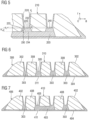
- Figure 5 shows another partial cross section of a tire tread 210 in accordance with another example of the present invention.
- the groove reinforcement 203 of Figure 5 has a support portion 230 which extends in an outer radial direction r essentially up to a tread wear indicator (TWI) height.
- TWI tread wear indicator
- a tread wear indicator 240 has only been shown in an adjacent groove.
- Such an indicator could have the radial height h t of 1.6 mm, or between 1.4 mm and 1.8 mm.
- the support portion 230 could also extend radially beyond the tread wear indicator 240 e.g. up to 1 mm above the treadwear indicator 240.
- the sidewall layers 220 could extend (with essentially uniform thickness) from the radially outer surface of the tread 210 at least down to a position which is about 1 mm radially above the treadwear indicator 240. This may still allow relatively uniform wear and performance until the tire is almost worn down to the treadwear indicator's upper surface.
- a main idea is to provide groove reinforcement sidewall layers which are essentially uniform in thickness during wear of the tire. This is in contrast to prior art which has typically tapering shapes of the reinforcement of the groove reinforcement or even no reinforcement at all in a portion close to the outer surface of the tread.
- the support portion 230 of Figure 4 with its base side 234 and top side 232 connected by lateral sides 233 is thicker in the radial direction as indicated by height h' bp .
- the groove support portion 230 extends radially beyond the bottom of the groove 225.
- Figure 6 shows yet another embodiment of a tread 310 in accordance with the present invention. Similar to the embodiment of Figure 3 , it has a tread cap having a shoulder region 306, ribs/blocks 308, grooves 305, a base layer 304 and a conductive passage 311. In contrast to the embodiment of Figure 3 , the embodiment of Figure 6 has a plurality of separate groove reinforcements 303 having each a support portion supporting two opposing sidewall layers of the groove reinforcement 303 and forming the reinforced groove 305. Although not indicated in Figure 6 , the support portions could extend until or above an upper side or a tread wear indicator as shown in the context of Figure 5 . Typically, the base side of the support portion is axially at least 50% broader than the bottom of the reinforced groove 305. For instance, the support portion extends essentially in a radial inner direction down to the upper side of the base layer 304.
- Figure 7 shows yet another embodiment of a tread 410 in which the two center grooves 405 are reinforced by a mutual reinforcement 403 extending over the axial width of both grooves. Separately from that reinforcement there are two single reinforcements 303, each reinforcing one of the axially outer grooves. Apart from that, tread 410 has also the tread cap with tread cap compound 402, shoulder regions 406, ribs/blocks 408, a conductive passage 411 through the base layer 404, as also shown in other embodiments herein.
- Figures 8 and 9 show top views of a tire tread of prior art tires and a tire in accordance with an embodiment of the present invention.
- Figure 8 shows top views of an unworn tread 10 ( Figure 8a ) and the same tread 10 in a worn state ( Figure 8b ) of the prior art tread already shown in Figure 1 .
- the unworn surface of the tread 10 shows almost only the tread cap with tread cap compound 2.
- Only the two center grooves 5 show adjacent circumferential stripes of groove reinforcement compound of the groove reinforcements 3.
- the image appears different as shown in Figure 8b .
- Figure 9 refers to the embodiment of Figure 3 which is an example in accordance with the present invention.
- Figure 9a shows a schematic top view of the unworn tread 110 and Figure 9b of the worn tread 110.
- all four grooves 105 have on each of their lateral sides a sidewall layer of groove reinforcement material of the groove reinforcement 3.
- Tread ribs are made of the cap compound of the cap 102.
- Figure 9b there is no significant change compared to Figure 9a visible.
- the change in Figure 8b compared to Figure 8a there is no significant change in the lateral tread cap compound width in the ribs 108 in Figure 9b compared to Figure 9a .
- All four grooves 105 are still axially encased by the reinforcement 103.
- Figure 10 shows another cross-sectional view of another embodiment of a tread 510 in accordance with the present invention.
- the tread 510 has a tread cap, shoulders 506, ribs/blocks 508, a reinforcement 503, a conductive passage 511 as well as a base layer 504.
- the tread cap compound 512 in the three central ribs 508 is different from the tread cap compound 502 in the shoulder area.
- the center ribs are still covered by the sidewall layers made of groove reinforcement compound.
- one, two, three, four or a plurality of center ribs may comprise a different compound than shoulder ribs while reinforced by the sidewall layers of the groove reinforcement.
- the groove reinforcement 503 encases also the compound of the center ribs. This may be of particular interest if the rib compounds tends to smear out of its initial position during molding and/or curing. In many cases, it shall be avoided that the material of the cap compound gets into the grooves or in particular to the groove bottom where it may trigger cracks over the lifetime of the tire.
- the essentially uniform layer of groove reinforcement compound extending from the top of the tread avoids such undesired behavior.
- Figure 11 discloses a tread 610 with similar arrangement as shown in Figure 10 with the main difference of having a third cap compound in the tread 610.
- the center rib comprises a first tread cap compound 622 while the two laterally adjacent ribs have a different, second tread cap compound 612 and the shoulder ribs even a further, third tread cap compound 602.
- the tire has shoulder regions 606, a groove reinforcement 603, a conductive passage 611, a base layer 604.
- the tread 710 has a special base layer 704 construction. While the tread cap 702, radially upper areas of the shoulder regions 706, ribs/blocks 708, the groove reinforcement 703 and the conductive passage 711 are similar to the corresponding elements described already with reference to Figure 3 , the base layer 704 has a different shape. The shape of the base layer 704 and its properties are described in more detail herein below. In particular, the base layer 704 has portions which extend in a radially outer direction in the skirt area 707 of the tire. These areas have an essentially triangular cross-sectional shape and could also be described as wings.
- the base layer 704 may have a relatively small radial thickness in an axial center portion of the tire, e.g. less than 15% or less than 10% of the maximum radial tread thickness of the tread base layer 704 or less than 30%, or preferably less than 20%, of the radial distance between the bottom of the axial center groove(s) to the radially inner side of the base layer 704 at the respective position.
- the tread base layer 704 has also a radially thicker portion, called here a cushion or cushioning portion 709, 709' between the central thin portion and the axially outermost region of the tread base 704 or tread 710.
- This cushion portion 709, 709' has a (maximum) thickness which is about between 110% and 30%, preferably between 95% and 50%, of the radial distance between the groove bottom of the center groove(s) and the radially inner side of the base layer 704 at the respective position of the groove(s).
- the cushion portion 709, 709' may extend axially over at least 30% (preferably at least 40% and/or at most 80%) of the distance ds, ds' between an axial outer edge of the base layer 704 in the shoulder region 706 and the groove closest to that shoulder region 706.
- the cushion portion 709, 709' may be considered as a circumferential portion of the base layer 704 which has a larger thickness than a portion of the base layer 704 adjacent the equatorial plane or in a portion radially below the grooves.
- each of the two shoulders of the tire has a cushion portion 709, 709' with a different shape.
- the tire could also have the same shape of the cushion portion 709, 709' on both sides instead.
- Said distance ds, ds' (as indicated in Figure 12 ) may also be understood as the axial distance between the axially outer edge of the base layer 4 and the radial projection of the groove bottom onto the radially inner side of the base layer 4.
- the cushion portion 709' may have essentially a trapezoidal shape having a radially inner broader support portion and a radially outer narrower portion.
- the cushion portion may taper in the radial outer direction.
- the base layer 704 may taper in the skirt portion 7 in the radially outer direction.
- the base layer 704 may extend in the skirt portion 704 beyond the maximum radial thickness of the cushion portion 9 as shown in Figure 12 .
- the latter may also have an essentially triangular shape and/or may increase in radial thickness from the adjacent skirt portion 707 towards the adjacent groove reinforcement 703 supporting the adjacent groove.
- tread compounds in the groove reinforcement, tread cap compounds or tread base layers
- a few examples are given herein below. Those shall however not be understood as necessarily limiting the invention to these examples.
- Table 1 provides examples of suitable base layer compounds. However, it shall be re-emphasized that the main focus of the invention is not directed to the specific compounds used. These base layer compound examples shall not automatically limit the invention.
- Table 1 - Base layer compound examples Sample number i ii iii iv Polybutadiene 65 50 0 0 Natural Rubber 35 50 100 100 Carbon Black 50 45 0 0 Pre-Silanized Silica 1 0 0 30 30 Phenol Formaldehyde resins 3 0 5 5 TDAE Oil 11.3 16 10 45 Waxes 2 1.5 3.8 3.8 Antidegradants 7 5.5 6.7 6.7 Stearic Acid 1 0.75 1 1 1 Sulfenamide Accelerator 0.6 1.4 0.9 0.9 Zinc oxide 3.5 2 2 2 Sulfur 2.8 1.9 2.5 2.5 1 Agilon 400 ® pre-silanized silica from PPG Industries.
- Table 2 shows Shore A hardness values of the samples shown above in Table 1.
- Table 2 - Base layer compound examples Sample number i ii iii iv Shore A Hardness a 49 54 29 17 a Shore A hardness measured according to ASTM D2240.
- Table 3 gives examples of suitable tread cap compounds. As mentioned already in the context of tread base layer compounds, it is emphasized again that such tread cap compounds mentioned herein are essentially considered as examples while other tread cap compounds could be used as long as they fall within the scope of the present invention.
- Table 3 - Tread cap compound examples Sample number v vi vii Functionalized SSBR 1 60 49 0 Natural Rubber 40 21 60 ESBR 2 0 0 40 Non-functionalized SSBR 3 0 30 0 Tackifier Resin 4 0 0 6 Carbon Black 3 1 0 Silica 80 66 30 Oils 16 12 0 Waxes 1.5 2 1.5 Fatty Acid Soap 0 0 2 Silane 6.4 5.2 5 Fatty Acid 0 0 3 Antidegradants 3.5 0 3.5 Stearic Acid 2 4 0 Sulfenamide Accelerator 2.4 2.4 3 Dithiophosphate Zinc Salt 0.8 0.8 0 Zinc oxide 3 3 3 3 Sulfur 1.5 1.5 1.2 Diphenylguanidine 0 0 1.5 1 Thio-functional
- Table 4 shows Shore A hardness values of the example compositions of Table 3.
- Table 4 - Tread cap compound examples Sample number v vi vii Shore A Hardness a 50 55 60 a Shore A hardness measured according to ASTM D2240.
- suitable groove reinforcement rubber compounds may for instance be found in United States Patent Publication No. 2018/0134086 A1 , see in particular in Examples 1, 2, 3, 4 and 5 of United States Patent Publication No. 2018/0134086 A1 .
- Such compounds have high Shore A hardness covered by the ranges of some embodiments mentioned herein. For the sake of illustration, two of the examples of that publication are listed herein below in Tables 5 to 8. Moreover, the whole content of US 2018/0134086 A1 is incorporated herein by reference.
- Table 6 shows high Shore A hardness values above 80 as well as considerable elongation at break values over 300% for the compounds 1 to 4 of Table 5.
- Table 6 - Groove reinforcement compounds Sample number 1 2 3 4 Shore A a 83.3 81.8 83 85.6 Elongation at break (%) b 329 359 390 426 a Shore A hardness measured according to ASTM D2240. b Ring sample test based on ASTM D412 and DIN 53504.
- Table 7 lists further examples of potential compounds that could be used as groove reinforcement rubber compounds.
- Table 7 - Groove reinforcement compounds continued Sample number 5 6 7 8 9 Polybutadiene 20 20 20 20 20 20 Natural Rubber 80 80 80 80 80 Carbon Black 50 50 50 50 Waxes 1.5 1.5 1.5 1.5 1.5
- Table 8 shows again high Shore A hardness values as well as considerable elongation at break values for the materials 5-9 of Table 7.
- Table 8 - Groove reinforcement compounds continued Sample number 5 6 7 8 9 Shore A Hardness 86 85.4 86.6 89.3 90.6 Elongation at Break (%) 508 518 508 481 502
- Shore A hardness values may, if desired, be higher than in the base layer compound or the tread cap compound. Moreover, elongation at break is higher than 300% in all samples. However, this shall not be indispensable for the scope of the present invention.
- the tread cap layer, the groove reinforcement and the tread base layer may be extruded together to form the tread as known to the person skilled in the art of extrusion and/or tire building.
- gear pumps and/or triplex or quadruplex extruders could be used.
Description
- The present invention is directed to a tire tread and a tire comprising a tread.
- Pneumatic tires include treads having a considerable influence on a plurality of properties of the tire, including for instance rolling resistance, wet grip and noise. One source of increased rolling resistance is the deformation of the tread in the area of the tread grooves and adjacent tread blocks or ribs which results in the generation of heat, increasing rolling resistance. The tire's performance is impacted by such deformations as well. For instance, cornering stiffness is limited. In order to overcome such deficiencies, multiple ways of improving groove stiffness have been suggested in the prior art.
- One example is disclosed in
United States Patent Application Publication No. 2014/0069560 A1 . This patent application discloses groove reinforcements which extend in a circumferential direction along the tread grooves. In particular, such reinforcements comprise a compound which is relatively stiff compared to the compound which is provided in the tread ribs and laterally outer tread of the tire. -
United States Patent Application Publication No. 2016/0167440 A1 discloses also groove reinforcements which can be each asymmetric with respect to the center of the groove reinforced. -
United States Patent Application Publication No. 2018/0134086 A1 discloses a tire tread in accordance with the preamble of claim 1. In particular, it shows groove reinforcements which extend also in an axial direction over multiple grooves such that the groove reinforcements of the circumferential grooves are integrally connected to one another in an axial direction. The tread intended to contact the road is made of a softer compound than the reinforcement. -
United States Patent Application Publication No. 2010/0154948 A1 discloses a tire tread with groove reinforcement comprising fibers which is basically a lining material within the groove. However, fiber material may be difficult to mix homogeneously into the composition. Inhomogeneities may result in areas of too high fiber concentration which may increase the probability of groove cracks. Moreover, fibers may impair recycling of unused rubber compound as fibers might end up in compounds which shall not include fibers if the new use is not limited accordingly. - These prior art approaches focus on influencing the tire's performance or properties essentially by modifying the properties of the outer tread layer and groove reinforcements.
- Attention is drawn to the disclosure of late published Art. 54(3)
document EP 3 670 168 A1 , which lacks a third tread layer comprising a third rubber compound. - While such approaches may have provided some benefit over earlier designs, still room for improvement remains.
- A first object of the invention may be to provide an advanced tire tread.
- A second object of the invention may be to provide advanced cornering stiffness of the tire and/or treadwear.
- A third object of the invention may be to help keeping the properties of the tire tread similar during wear.
- Another object of the invention may be to avoid smearing of tread cap compounds into the grooves and to avoid potential groove cracking due to impurities in the groove reinforcement.
- The present invention is defined by the scope of independent claim 1. Further preferred embodiments are provided in the dependent claims and the summary and description herein below.
- In a first aspect of the invention, a tire tread is provided, wherein the tread has circumferential tread grooves and comprises a tread cap comprising a first rubber compound for contacting the road when driving and at least one circumferential groove reinforcement forming (or encasing) at least one of the grooves in the tread cap, the groove reinforcement comprising a second rubber compound for reinforcing an area adjacent the grooves formed by the groove reinforcement, wherein the groove reinforcement comprises for at least one of the grooves formed by the groove reinforcement two groove sidewall layers (in particular per groove formed by the groove reinforcement), each sidewall layer extending from the radially outer (or outermost) surface of the unworn tread down into the direction of the bottom of the groove formed by the groove reinforcement and wherein each sidewall layer has an essentially uniform or essentially constant thickness along its length (extension from the radially outer surface of the tread in the direction of the bottom of the groove), and wherein the groove reinforcement comprises a groove support or base portion forming a bottom portion of the groove and having a radially inner base side (or base area) as well as a radially outer top side (or top area), wherein the groove support portion tapers from its base side to its top side. The tread further comprises a tread base layer arranged radially inwards of the tread cap and comprising a third rubber compound, wherein the groove reinforcement extends in a radially inner direction at least onto the radially outer surface of the base layer. Moreover, the base side of the groove support portion is from 1.1 to 5 times longer than the axial width of the bottom of the reinforced groove. Such an arrangement provides a uniform support to the radially upper area of the groove and substantially supports also the bottom of the groove by means of the support portion. The groove reinforcement helps to provide uniform properties over wear in tire life. Also smearing of the tread cap compound in the cap areas adjacent the grooves can be avoided during molding and/or curing. In general, such a far extension of the groove reinforcement may result in a good support of the groove area above the reinforcement
- In still another embodiment, the groove support portion has an essentially trapezoidal shape tapering from the base side to the top side. In general, this covers the possibility that the lateral sides of the trapezoidal shape are straight, convex or concave. The tapering or trapezoidal shape may further improve the supporting function.
- In yet another embodiment, the groove support portion extends in a radially outer direction at most 1 mm above the radial height of the radial upper surface of a tread wear indicator of the groove reinforced by the groove reinforcement, optionally at most to the radial height of the radially upper surface of the tread wear indicator or optionally at most essentially up to the bottom of the groove, and wherein the sidewall layers extend to the radially outer side of the groove support portion. This arrangement improves further the constant properties of the tread over wear while allowing at the same time good support properties.
- In general, the support portion or its top portion or side may end where the sidewall layers (defined by the uniform thickness) start. This shall not mean that the sidewall layers and the support portion are separate element rather they are supposed to be integrally formed or connected. Also, the support portion may have a bottom portion or base side which is not necessarily the end of the groove reinforcement in a radial inner direction. Rather, the term support portion may be understood as portion or area of the groove reinforcement supporting the groove bottom area. However, that shall not be understood in a sense that said tapering shape may be arbitrarily found in any reinforcement of any shape. The shapes claimed herein are supposed to be still visible within their meaning and should not be arbitrarily chosen. Moreover, essentially uniform thickness shall be understood herein as uniform thickness or uniform thickness within the boundaries of manufacturing accuracy. In an embodiment, essentially uniform thickness of the sidewall layers may mean that the thickness over the length of a side wall layer deviates from the average thickness of that sidewall layer by less than 10%, preferably by less than 5%.
- In still another embodiment, the groove support portion and the sidewall layers are integrally formed.
- In yet another embodiment, the base side is (laterally or axially) longer than the top side, and the groove support portion has two lateral sides connecting the base side and the top side, and wherein one or both lateral sides may have one of a convex shape, concave shape and straight shape. There may be deviations from a perfect shape of a trapezoid. In general, also top and base side may deviate from a perfect parallel arrangement within the boundaries of normal manufacturing accuracy.
- In another embodiment, the base side is (laterally or axially) longer than the top side, and the groove support portion has two lateral sides connecting the base side and the top side, wherein the angle between at least one of the lateral sides and the base side is at most 85°, optionally at most 80° and at least 30°. This can be considered as a measure for the average slope between edges of the top side and the base side. Such a slope may help to improve support function of the reinforcement for the bottom area of the groove.
- In still another embodiment, the tread has a tread base layer arranged radially inwards of the tread cap and the groove reinforcement, wherein the radial height of the groove support portion is at least one of 20%, 50% and 80% of the radial distance between the bottom of the groove and a radial upper side of the tread base layer. Thus, the tread base portion has a substantial radial thickness for supporting the groove's stiffness and stability.
- In still another embodiment, the base side of the support portion is from from 1.2 to 4 times longer than the axial width of the bottom of the reinforced groove. This range helps to support the stability of the area around or adjacent the groove.
- In still another embodiment, the sidewall layer has a thickness from 0.5 mm to 5 mm, optionally from 0.5 mm to 2 mm. Such thickness ranges provide a good compromise between reinforcement and remaining width of tread cap compounds in the ribs or blocks.
- In still another embodiment, the groove sidewall layers extend from the (radially outermost) top of the unworn tread (in particular, at the axial position of the reinforced groove) at least over 70% of the depth of the groove measured in parallel to the sidewall of the groove (over this extension the sidewall layers have essentially uniform thickness). In general, the length of a sidewall layer of a groove mentioned herein is viewed from the radial top of the tread into the direction of the bottom of the groove reinforced by the groove reinforcement, unless indicated otherwise herein.
- In still another embodiment, the axial diameter of the top side of the groove support portion corresponds essentially to the sum of the axial diameters of the sidewall layer and the inside axial diameter of the groove, at the radial height of the top side of the groove support portion.
- In yet another embodiment, a ratio between thickness of the sidewall layer and length (viewed along the height of the groove or sidewall, respectively) of the sidewall layer having uniform thickness is at most 1:10, optionally at most 1:15. In other words this is viewed in a planar cross section perpendicular to the circumferential direction (in parallel to the radial and axial directions). This demonstrates how long and relatively thin the sidewall layers may extend.
- In another embodiment, all grooves of the tire are reinforced with said groove reinforcement. However, not all grooves need to have necessarily exactly the same dimensions of reinforcement as long as being within the scope of the claimed invention.
- In another embodiment, at least two opposite sidewall layers of a reinforced groove have essentially the same uniform thickness and/or at least two opposite sidewall layers of a reinforced groove have essentially the same length when the tread is unworn (measured perpendicularly to the circumferential direction).
- In still another embodiment, at least one of the sidewall layers and a line connecting an axial edge of the top side and an axial edge of the base side at said sidewall layer intersect with an angle of between 175° and 90°, optionally between 170° and 100°. This is again an example of the advanced supporting function.
- In still another embodiment, the tread (and/or a tire comprising the tread) has an axially innermost side and an axially outermost side and the sidewall layers of (preferably at least two or three) reinforced grooves are thicker on an axially outer side of the groove compared to an axially inner side of the same groove. Such an arrangement can help to improve further the cornering stiffness and/or behavior of the tread. The thickness of each sidewall layer as such can still have essentially uniform thickness, it may just be different for the two different sides of the groove.
- In still another embodiment, the tread (and/or a tire comprising the tread) has an axially innermost side and an axially outermost side, wherein the sidewall layers of one or two axially outermost circumferential grooves are thicker than of another groove axially closer to the innermost side of the tread or tire. Such an arrangement can also help to improve further the cornering stiffness and/or behavior of the tread.
- In yet another embodiment, the groove reinforcement compound has a Shore A hardness of at least 75, optionally of at least 80 (and at most 100), and an elongation at break of at least 300%, wherein the tread cap compound has a Shore A hardness from 40 to 80, and wherein the Shore A hardness of the groove reinforcement compound is higher than the Shore A hardness of the tread cap compound. This may help to improve cornering stiffness while keeping driving comfort and/or noise at an acceptable level. Shore A hardness is determined according to ASTM D2240 or equivalent. Elongation at break is determined according to ASTM D412 or equivalent.
- In another embodiment of the tread, the tread cap rubber compound has a Shore A hardness from 45 and 80 and the groove reinforcement rubber compound has a Shore A hardness from 70 to 100 and, optionally, a tread base layer rubber compound has a Shore A hardness from 15 to 55. The Shore A hardness of the groove reinforcement rubber compound is higher than the Shore A hardness of the tread cap compound while the Shore A hardness of the tread cap compound is higher than the Shore A hardness of the tread base layer compound. Such a distribution of stiffnesses of said three tread compounds is desirable to provide stiff grooves as well as a relatively soft base which supports better driving comfort at limited tread wear.
- In another embodiment, the tread cap rubber compound has a Shore A hardness from 50 to 65 and the base layer has a Shore A hardness from 15 to 50, optionally from 15 to 45 or even from 20 to 40. Such a combination can further reduce noise generation and/or increase driving comfort.
- In another embodiment, the groove reinforcement has a Shore A hardness from 75 to 100, optionally from 80 to 100 or from 80 to 99. Such values of relatively high stiffness are most desirable for the groove reinforcement compound. In general, it is also possible that the groove reinforcement is as such reinforced by fiber material within the compound.
- In another embodiment, the groove reinforcement is essentially free of fibers.
- In another embodiment, the Shore A hardness of the tread cap compound is at least 5% (optionally at least 10%) lower than the Shore A hardness of the groove reinforcement compound and/or the Shore A hardness of the base layer compound is at least 5% (optionally at least 10%) lower than the Shore A hardness of the tread cap compound. Alternatively, or in addition, the above values could be at most 30% lower than mentioned above.
- In still another embodiment, the tread base layer extends at least over the axial width of the radially inner bottom of the tread cap. This can further increase the effects of the desired combination of compounds.
- In still another embodiment, the groove reinforcement extends at least over an axial width of one, two, three or more grooves and/or all grooves. However, even if the groove reinforcement extends over the width of multiple grooves (and may be considered to have a comb-like cross section), the ribs or blocks have in general still the tread cap compound in a central portion.
- In yet another embodiment, the tread base layer supports the outer axial ends of the tread cap or in other words supports the tread cap in the shoulder region of the tire.
- In yet another embodiment, the groove reinforcement extends at its radially inner portion over from 30% to 60% of the width of the tread base layer.
- In still another embodiment, the base layer has at one or both of its axial ends a skirt (or wing) portion in which the base layer is radially thicker than in an area axially closer or adjacent to the equatorial plane (EP) of the tire. In other words, in the skirt portion, the radial thickness of the (relatively soft) base layer is larger than radially below (an area of) the grooves. This can help to soften the shoulder region and reduce noise.
- In still another embodiment, the radial thickness of the base layer radially below the grooves is at most 20% of the radial distance between the bottom of a center groove and the radially inner side of the base layer. This is desirable for the stability of the tire in the claimed combination of hardness properties.
- In yet another embodiment, in a portion of at least one shoulder region of the tread (in a cushion portion), the radial thickness of the base layer is between 110% and 40%, optionally between 90% and 50%, of the radial distance between the bottom of a center groove and the radially inner side of the base layer. This arrangement can act as a cushion in the shoulder region with lower hardness than in the radially above arranged tread cap material. A center groove may be either a groove contacting the equatorial plane of the tire or the axially next groove to the equatorial plane of the tire. In case of two equally distant grooves with respect to the equatorial plane with same depth either one of them may be considered, in case of two equally distant grooves with different depths, the deeper groove may be considered, e.g. the groove with the smaller radial distance between its bottom and the radially inner side of the tread base layer.
- In yet another embodiment, a circumferential groove, being closer to the equatorial plane than another circumferential groove, may have a groove reinforcement with a higher Shore A hardness, than the groove reinforcement of said other groove. In particular, one or more groove reinforcements adjacent the equatorial plane of the tire may comprise a compound having a Shore A hardness from 75 to 100 while other grooves axially or laterally further away from the equatorial plane of the tire have a Shore A hardness of from 60 to 80. This arrangement of grooves reinforcements with decreasing hardness in the lateral direction from groove to groove may further help to balance the properties of the tire tread. In particular, this may help to provide good cornering stiffness in the center of the tread while having softer material in the direction of the shoulder of the tire which may help to find a better compromise between stiffness, noise and/or damping.
- In an embodiment, the base layer has a cushion portion between an axially outer edge of the base layer and the groove axially nearest to that edge, wherein the cushion portion extends axially over at least 30% (preferably at least 40%) of the distance ds between said axial outer edge of the base layer and said groove. In other words, the cushion portion may be considered as a circumferential portion of the base layer which has a larger thickness than a portion of the base layer adjacent the equatorial plane or in a portion radially below the grooves, respectively. The cushion portion may in general be made of the same material/compound as the rest of the base layer. Said distance ds may also be understood as the axial distance between the axially outer edge of the base layer and the radial projection of the groove bottom onto the radially inner side of the base layer, in particular the axially outer edge of the radial projection of the groove bottom onto the radially inner side of the base layer.
- In another embodiment, the cushion portion may have a tapering and/or trapezoidal shape, e.g. tapering in the radial direction, having a smaller axial width at its radially outer side and a larger axial with at its radially inner side. Such an arrangement may be advantageous for stability reasons.
- In still another embodiment, the radial thickness of the base layer is one or more of: in an axially outermost region of the base layer between 50% and 120% of the radial distance between a bottom of a center groove and the radial inner side of the base layer; in a second region axially inwards of said outer region between 10% and 20% of the radial distance between a bottom of a center groove and the radial inner side of the base layer; in a third region axially inwards of said second region between 50% and 110% of the radial distance between a bottom of a center groove and the radial inner side of the base layer; and in a fourth region axially inwards of said third region between 1 % and 20% of the radial distance between a bottom of a center groove and the radial inner side of the base layer. Said axially outer portion could be absent in an alternative embodiment such that only the cushion portion axially inwards of the skirt region and the fourth portion are present.
- Axially inwards or inner shall mean in general in the present application, axially closer to the equatorial plane of the tire. Axially outwards or outer is axially further from the equatorial plane of the tire. Axial direction means also a direction in parallel to the axis of rotation of the tire. Similarly, radially outwards or outer means further away from the axis of rotation of the tire and radially inwards or inner means closer to the tire's axis of rotation. The circumferential direction may be considered as rotation-symmetric to the axis of rotation of the tire. The terms center and central may be replaceable which each other in the present application. If deemed appropriate it would also be possible to make reference to the centerline of the tread instead of the equatorial plane of the tire or tread herein. Both terms are known to the person skilled in the art.
- In another embodiment, the tread cap comprises at least two tread cap layers arranged radially on top of one another. Such tread cap layers may have different compounds with different properties. For instance, a radially lower tread cap layer could be stiffer than the radially upper cap layer. For instance, a radially inner tread cap layer may have a smaller rolling resistance than the radially outer cap layer. A radially outer tread cap layer may have a higher wet grip than the radially inner tread cap layer.
- In another embodiment, the groove reinforcement covers the bottom of the adjacent groove (reinforced by the reinforcement) and at least a bottom portion of at least one of the sidewalls of said groove.
- In another embodiment, the groove reinforcement extends from the radially outer surface of the tread (the surface contacting the road when driving) in a radially inner direction below the bottom of the reinforced groove or grooves, optionally down to the radially outer side of the base layer. In general, the groove reinforcement or reinforcements may extend in a radial direction below the bottom of the grooves. A portion of the tread cap layer could be between the reinforcement(s) and the tread base layer or one or more reinforcement(s) extend radially inwards to contact the tread base layer or one or more reinforcements extend radially inwards through the base layer to contact a tire belt or belt overlay.
- In still another embodiment, at least one of the groove reinforcements extends from the radially outer surface of the tread through the base layer, wherein the groove reinforcement rubber compound comprises at least 40 phr carbon black. This may render the groove reinforcement sufficiently electrically conductive such that an electrically conductive path is provided from the tread surface to the belt region of the tire. This may be of particular interest in case the tread cap compound and/or the base layer compound does not comprise sufficiently conductive material, e.g. high silica compounds. Thus, the degree of design freedom is increased.
- In still another embodiment, the elongation at break of the groove reinforcement rubber compound is larger than 300 %, optionally smaller than 700%. Such a minimum for elongation at break helps to avoid groove cracks.
- In general, the rubber compounds or compositions of the tread cap, base layer and the groove reinforcements may be different. It is also emphasized that the layers and components discussed herein are not part of the tire carcass or belt or belt overlays.
- In one embodiment of this invention, one or more of the rubber compositions may include at least one and/or one additional diene-based rubber. Representative synthetic polymers may be the homopolymerization products of butadiene and its homologues and derivatives, for example, methylbutadiene, dimethylbutadiene and pentadiene as well as copolymers such as those formed from butadiene or its homologues or derivatives with other unsaturated monomers. Among the latter may be acetylenes, for example, vinyl acetylene; olefins, for example, isobutylene, which copolymerizes with isoprene to form butyl rubber; vinyl compounds, for example, acrylic acid, acrylonitrile (which polymerize with butadiene to form NBR), methacrylic acid and styrene, the latter compound polymerizing with butadiene to form SBR, as well as vinyl esters and various unsaturated aldehydes, ketones and ethers, e.g. acrolein, methyl isopropenyl ketone and vinylethyl ether. Specific examples of synthetic rubbers include neoprene (polychloroprene), polybutadiene (including cis-1,4-polybutadiene), polyisoprene (including cis-1,4-polyisoprene), butyl rubber, halobutyl rubber such as chlorobutyl rubber or bromobutyl rubber, styrene/isoprene/butadiene rubber, copolymers of 1,3-butadiene or isoprene with monomers such as styrene, acrylonitrile and methyl methacrylate, as well as ethylene/propylene terpolymers, also known as ethylene/propylene/diene monomer (EPDM), and in particular, ethylene/propylene/ dicyclopentadiene terpolymers. Additional examples of rubbers which may be used include alkoxy-silyl end functionalized solution polymerized styrene-butadiene rubber(SBR), high cis-1,4-polybutadiene rubber (PBR), isoprene-butadiene rubber (IBR) and styrene-isoprene-butadiene rubber (SIBR). These rubbers can also optionally be silicon-coupled or tin-coupled star-branched polymers. The preferred rubbers or elastomers are generally natural rubber, synthetic polyisoprene rubber, polybutadiene rubber, and styrene-butadiene rubber (SBR), including SBR made by emulsion polymerization (ESBR) and SBR made by solution polymerization (SSBR).
- Preferred rubber or elastomers may be in general natural rubber, synthetic polyisoprene, polybutadiene and SBR including SSBR. In another embodiment, the composition may comprise at least two diene-based rubbers. For example, a combination of two or more rubbers is preferred such as cis 1,4-polyisoprene rubber (natural or synthetic, although natural is preferred), 3,4-polyisoprene rubber, styrene/isoprene/butadiene rubber, emulsion and solution polymerization derived styrene/butadiene rubbers, cis 1,4-polybutadiene rubbers and emulsion polymerization prepared butadiene/acrylonitrile copolymers. In another embodiment, solution polymerization prepared SBR (SSBR) may be used. Such an SSBR may for instance have a bound styrene content in a range of 5 to 50, preferably 9 to 36, percent. The SSBR can be conveniently prepared, for example, by anionic polymerization in an inert organic solvent. More specifically, the SSBR can be synthesized by copolymerizing styrene and 1,3-butadiene monomer in a hydrocarbon solvent utilizing a organo lithium compound as the initiator.
- In one embodiment, a synthetic or natural polyisoprene rubber may be used. Synthetic cis 1,4-polyisoprene and cis 1,4-polyisoprene natural rubber are as such well known to those having skill in the rubber art. In particular, the cis 1,4-content may be at least 90%, optionally at least 95%. In one embodiment, cis 1,4-polybutadiene rubber (BR or PBD) is used. Suitable polybutadiene rubbers may be prepared, for example, by organic solution polymerization of 1,3-butadiene. The BR may be conveniently characterized, for example, by having at least a 90 percent cis 1,4-content and a glass transition temperature (Tg) in a range of -95°C to -105°C. Suitable polybutadiene rubbers which are available commercially from The Goodyear Tire & Rubber Company include Budene® 1207 high cis-1,4-polybutadiene rubber, Budene® 1208 high cis-1,4-polybutadiene rubber, and Budene® 1280 high cis-1,4-polybutadiene rubber. These high cis-1,4-polybutadiene rubbers can be synthesized utilizing nickle catalyst systems which include a mixture of (1) an organonickel compound, (2) an organoaluminum compound, and (3) a fluorine containing compound as described in
United States Patent 5,698,643 andUnited States Patent 5,451,646 . The teachings ofUnited States Patent 5,698,643 andUnited States Patent 5,451,646 are incorporated herein by reference. - A reference to a glass transition temperature, or Tg, of an elastomer or elastomer composition, where referred to herein, represents the glass transition temperature(s) of the respective elastomer or elastomer composition in its uncured state or possibly a cured state in a case of an elastomer composition. A Tg can be suitably determined as a peak midpoint by a differential scanning calorimeter (DSC) at a temperature rate of increase of 10°C per minute.
- The term "phr" as used herein, and according to conventional practice, refers to "parts by weight of a respective material per 100 parts by weight of rubber, or elastomer." In general, a composition comprises 100 parts of rubber/elastomer. The claimed composition may comprise other rubbers/elastomers than explicitly mentioned in the claims, provided that the phr value of the claimed rubbers/elastomers is in accordance with claimed phr ranges and the amount of all rubbers / elastomers in the composition results in total in 100 parts of rubber. In an example, the composition may further comprise from 1 to 10 phr, optionally from 1 to 5 phr of one or more additional diene-based rubbers, such as SBR, SSBR, ESBR, PBD/BR, NR and/or synthetic polyisoprene. In another example, the composition may include less than 5 phr, preferably less than 3 phr of an additional diene-based rubber or be also essentially free of such an additional diene-based rubber. The terms "compound" and "composition" may be used herein interchangeably, unless indicated otherwise.
- In an embodiment, the rubber composition may also include oil, in particular processing oil. Processing oil may be included in the rubber composition as extending oil typically used to extend elastomers. Processing oil may also be included in the rubber composition by addition of the oil directly during rubber compounding. The processing oil used may include both extending oil present in the elastomers, and process oil added during compounding. Suitable process oils may include various oils as are known in the art, including aromatic, paraffinic, naphthenic, vegetable oils, and low PCA oils, such as MES, TDAE, SRAE and heavy naphthenic oils. Suitable low PCA oils may include those having a polycyclic aromatic content of less than 3 percent by weight as determined by the IP346 method. Procedures for the IP346 method may be found in Standard Methods for Analysis & Testing of Petroleum and Related Products and British Standard 2000 Parts, 2003, 62nd edition, published by the Institute of Petroleum, United Kingdom.
- In an embodiment, the rubber composition may include silica. Commonly employed siliceous pigments which may be used in the rubber compound include for instance conventional pyrogenic and precipitated siliceous pigments (silica). In one embodiment, precipitated silica is used. The conventional siliceous pigments may be precipitated silicas such as, for example, those obtained by the acidification of a soluble silicate, e.g., sodium silicate. Such conventional silicas might be characterized, for example, by having a BET surface area, as measured using nitrogen gas. In one embodiment, the BET surface area may be in the range of 40 to 600 square meters per gram. In another embodiment, the BET surface area may be in a range of 80 to 300 square meters per gram. The BET method of measuring surface area is described in the Journal of the American Chemical Society, Volume 60, Page 304 (1930). The conventional silica may also be characterized by having a dibutylphthalate (DBP) absorption value in a range of 100 to 400, alternatively 150 to 300. A conventional silica might be expected to have an average ultimate particle size, for example, in the range of 0.01 to 0.05 micron as determined by the electron microscope, although the silica particles may be even smaller, or possibly larger, in size. Ranges of silica use could be for instance between 5 and 120 phr, preferably in a range of between 20 and 70 phr or 80 to 120 phr. Various commercially available silicas may be used, such as, only for example herein, and without limitation, silicas commercially available from PPG Industries under the Hi-Sil trademark with
designations 210, 243, etc; silicas available from Rhodia, with, for example, designations of Z1165MP and Z165GR and silicas available from Degussa AG with, for example, designations VN2 and VN3, etc. - In an embodiment, the rubber composition may include carbon black. Representative examples of such carbon blacks include N110, N121, N134, N220, N231, N234, N242, N293, N299, N315, N326, N330, N332, N339, N343, N347, N351, N358, N375, N539, N550, N582, N630, N642, N650, N683, N754, N762, N765, N774, N787, N907, N908, N990 and N991 grades. These carbon blacks have iodine absorptions ranging from 9 to 145 g/kg and DBP number ranging from 34 to 150 cm3/100 g.
- In one embodiment the rubber composition may contain a conventional sulfur containing organosilicon compounds or silanes. Examples of suitable sulfur containing organosilicon compounds are of the formula:
Z-Alk-Sn-Alk-Z I
- in which Z is selected from the group consisting of

- where R1 is an alkyl group of 1 to 4 carbon atoms, cyclohexyl or phenyl; R2 is alkoxy of 1 to 8 carbon atoms, or cycloalkoxy of 5 to 8 carbon atoms; Alk is a divalent hydrocarbon of 1 to 18 carbon atoms and n is an integer of 2 to 8. In one embodiment, the sulfur containing organosilicon compounds are the 3,3'-bis(trimethoxy or triethoxy silylpropyl) polysulfides. In one embodiment, the sulfur containing organosilicon compounds are 3,3'-bis(triethoxysilylpropyl) disulfide and/or 3,3'-bis(triethoxysilylpropyl) tetrasulfide. Therefore, as to formula I, Z may be

- where R2 is an alkoxy of 2 to 4 carbon atoms, alternatively 2 carbon atoms; Alk is a divalent hydrocarbon of 2 to 4 carbon atoms, alternatively with 3 carbon atoms; and n is an integer of from 2 to 5, alternatively 2 or 4. In another embodiment, suitable sulfur containing organosilicon compounds include compounds disclosed in
U.S. Patent 6,608,125 . In one embodiment, the sulfur containing organosilicon compounds includes 3-(octanoylthio)-1-propyltriethoxysilane, CH3(CH2)6C(=O) -S-CH2CH2CH2Si(OCH2CH3)3, which is available commercially as NXT™ from Momentive Performance Materials. In another embodiment, suitable sulfur containing organosilicon compounds include those disclosed inU.S. Patent Publication No. 2003/0130535 . In one embodiment, the sulfur containing organosilicon compound is Si-363 from Degussa. The amount of the sulfur containing organosilicon compound in a rubber composition may vary depending on the level of other additives that are used. Generally speaking, the amount of the compound may range from 0.5 to 20 phr. In one embodiment, the amount will range from 1 to 10 phr. - It is readily understood by those having skill in the art that the rubber composition may be compounded by methods generally known in the rubber compounding art, such as mixing the various sulfur-vulcanizable constituent rubbers with various commonly used additive materials such as, for example, sulfur donors, curing aids, such as activators and retarders and processing additives, such as oils, resins including tackifying resins and plasticizers, fillers, pigments, fatty acid, zinc oxide, waxes, antioxidants and antiozonants and peptizing agents. As known to those skilled in the art, depending on the intended use of the sulfur vulcanizable and sulfur-vulcanized material (rubbers), the additives mentioned above are selected and commonly used in conventional amounts. Representative examples of sulfur donors include elemental sulfur (free sulfur), an amine disulfide, polymeric polysulfide and sulfur olefin adducts. In one embodiment, the sulfur-vulcanizing agent is elemental sulfur. The sulfur-vulcanizing agent may for instance be used in an amount ranging from 0.5 to 8 phr, alternatively with a range of from 1.5 to 6 phr. Typical amounts of tackifier resins, if used, comprise for example 0.5 to 10 phr, usually 1 to 5 phr. Typical amounts of processing aids, if used, comprise for example 1 to 50 phr (this may comprise in particular oil). Typical amounts of antioxidants, if used, may for example comprise 1 to 5 phr. Representative antioxidants may be, for example, diphenyl-p-phenylenediamine and others, such as, for example, those disclosed in The Vanderbilt Rubber Handbook (1978), Pages 344 through 346. Typical amounts of antiozonants, if used, may for instance comprise 1 to 5 phr. Typical amounts of fatty acids, if used, which can include stearic acid, may for instance comprise 0.5 to 3 phr. Typical amounts of waxes, if used, may for example comprise 1 to 5 phr. Often microcrystalline waxes are used. Typical amounts of peptizers, if used, may for instance comprise 0.1 to 1 phr. Typical peptizers may be, for example, pentachlorothiophenol and dibenzamidodiphenyl disulfide.
- Accelerators may be preferably but not necessarily used to control the time and/or temperature required for vulcanization and to improve the properties of the vulcanizate. In one embodiment, a single accelerator system may be used, i.e., primary accelerator. The primary accelerator(s) may be used in total amounts ranging from 0.5 to 4, alternatively 0.8 to 1.5, phr. In another embodiment, combinations of a primary and a secondary accelerator might be used with the secondary accelerator being used in smaller amounts, such as from 0.05 to 3 phr, in order to activate and to improve the properties of the vulcanizate. Combinations of these accelerators might be expected to produce a synergistic effect on the final properties and are somewhat better than those produced by use of either accelerator alone. In addition, delayed action accelerators may be used which are not affected by normal processing temperatures but produce a satisfactory cure at ordinary vulcanization temperatures. Vulcanization retarders might also be used. Suitable types of accelerators that may be used in the present invention are for instance amines, disulfides, guanidines, thioureas, thiazoles, thiurams, sulfenamides, dithiocarbamates and xanthates. In one embodiment, the primary accelerator is a sulfenamide. If a second accelerator is used, the secondary accelerator may be for instance a guanidine, dithiocarbamate or thiuram compound. Suitable guanidines include dipheynylguanidine and the like. Suitable thiurams include tetramethylthiuram disulfide, tetraethylthiuram disulfide, and tetrabenzylthiuram disulfide.
- The mixing of the rubber composition can be accomplished by methods known to those having skill in the rubber mixing art. For example, the ingredients may be typically mixed in at least two stages, namely, at least one non-productive stage followed by a productive mix stage. The final curatives including sulfur-vulcanizing agents may be typically mixed in the final stage which is conventionally called the "productive" mix stage in which the mixing typically occurs at a temperature, or ultimate temperature, lower than the mix temperature(s) than the preceding non-productive mix stage(s). The terms "non-productive" and "productive" mix stages are well known to those having skill in the rubber mixing art. In an embodiment, the rubber composition may be subjected to a thermomechanical mixing step. The thermomechanical mixing step generally comprises a mechanical working in a mixer or extruder for a period of time, for example suitable to produce a rubber temperature between 140°C and 190°C. The appropriate duration of the thermomechanical working varies as a function of the operating conditions, and the volume and nature of the components. For example, the thermomechanical working may be from 1 to 20 minutes.
- Vulcanization of the pneumatic tire of the present invention may for instance be carried out at conventional temperatures ranging from 100°C to 200°C. In one embodiment, the vulcanization is conducted at temperatures ranging from 110°C to 180°C. Any of the usual vulcanization processes may be used such as heating in a press or mold, heating with superheated steam or hot air. Such tires can be built, shaped, molded and cured by various methods which are known and will be readily apparent to those having skill in such art.
- In a second aspect of the invention, a tire is provided, the tire having a tread in accordance with one or more of the embodiments mentioned herein.
- Advantages of the tire comprising a tread in accordance with an aspect of the invention or one of its embodiments or combinations thereof have already been indicated above.
- The tire could for example be a pneumatic tire, in particular a pneumatic radial and/or passenger car tire. In another aspect of the invention a method of manufacturing a tire tread according to claim 1 is provided in claim 12. In particular, the method comprises the step of extruding the tread cap and the groove reinforcement at the same time, optionally with a multiplex extruder.
- In an embodiment, the step of extruding the tread cap and the groove reinforcement further includes extruding a tread base layer together with the tread cap and the groove reinforcement at the same time, optionally with a triplex extruder or quadruplex extruder.
- It is emphasized that one or more aspects, embodiments, or features thereof, maybe be combined with each other within the scope of the present invention.
- The structure, operation and advantages of the invention will become more apparent upon contemplation of the following description taken in conjunction with the accompanying drawings, wherein:
-
Figure 1 represents a schematic cross section of a tire tread comprising a groove reinforcement in accordance with the prior art; -
Figure 2 represents a schematic cross section of a tire tread comprising a groove reinforcement in accordance with another prior art example; -
Figure 3 is a schematic cross section of a tire tread in accordance with a first embodiment in accordance with the present invention; -
Figure 4 is showing a detail of the embodiment shown inFigure 3 ; -
Figure 5 shows a part of a cross section of a tire tread in accordance with another embodiment of the present invention with support portions of the groove reinforcement extending up to the height of a tread wear indicator; -
Figure 6 shows a cross section of another embodiment of a tire tread in accordance with another embodiment of the present invention which has a plurality of separate groove reinforcements; -
Figure 7 shows a cross section of another embodiment of a tire tread in accordance with still another embodiment of the present invention, having a plurality of groove reinforcements, with one reinforcement extending over the axial width of two grooves; -
Figure 8a shows a schematic partial top view of an unworn tire tread of the prior art tread shown inFigure 1 ; -
Figure 8b shows a schematic partial top view of a worn tire tread of the prior art tread shown inFigure 1 ; -
Figure 9a shows a schematic partial top view of an unworn tire tread in accordance with the example of the invention in accordance withFigure 3 ; -
Figure 9b shows a schematic partial top view of a worn tire tread in accordance with the example of the invention in accordance withFigure 3 ; -
Figure 10 shows a schematic cross section of a tire tread in accordance with still another embodiment of the invention, in which the tread cap compound in the three center ribs is different from the tread cap compound in a shoulder area of the tire; -
Figure 11 shows a schematic cross section of a tire tread in accordance with still another embodiment of the invention, in which the tread cap compound in the center rib is different from the tread cap compound in the two adjacent ribs and both said tread cap compounds being different from the tread cap compound in the shoulder ribs; and -
Figure 12 shows another schematic cross section of a tire tread similar to the embodiment shown inFigure 3 but having a tread base layer with cushion portions in the shoulder area of the tire. -
Figure 1 shows a schematic cross section of atire tread 10 in accordance with the prior art.Tread 10 has atread cap 2 with a plurality of circumferential ribs and/ortread blocks 8 betweencircumferential grooves 5. Moreover, saidtread 10 has atread base 4. Thetread base 4 or treadbase layer 4 is made of a different compound than thecap 2 and it supports thetread cap 2 on a radially inner side of thetread 10. Thetread base layer 4 has also extensions in axiallyouter regions 7 of the shoulder regions 6 of the tire, in other words in theskirt regions 7 of thetread 10. Thegrooves 5 are reinforced by a plurality of axially or laterally separatedgroove reinforcements 3. In other words, the groove reinforcements form or encase the bottoms of thegrooves 5 as well as at least parts of their sidewalls, i.e. the sidewalls of the ribs or blocks 8. The portions of thegroove reinforcements 3 covering the groove sidewalls are tapering and have a decreasing thickness along their length in an outer radial direction. The equatorial plane EP of the tire tread is indicated by dashed lines. AlthoughFigure 1 describes prior art, and for the sake of simplicity, the description of elements also present in figures in accordance with embodiments of the invention may apply also to these embodiments and their understanding. -
Figure 2 shows a schematic cross section of another prior art tread 10'. In contrast toFigure 1 , the groove reinforcement 3' is formed integrally over the axial width of multiple grooves. Again, the portions of the groove reinforcement 3' covering the sidewalls of the ribs or parts thereof do not have an essentially uniform thickness along their length but taper in an outer radial direction. -
Figure 3 shows a first example of atread 110 in accordance with the invention. Thetread 110 has a tread cap made oftread cap compound 102, a plurality of tread blocks and/orribs 108 largely made oftread cap compound 102, ashoulder portion 106, askirt portion 107 and a plurality ofcircumferential tread grooves 105 which are formed in the tread cap by thegroove reinforcement 103. In other words, one may also say that thegroove reinforcement 103 is embedded in thetread cap 102. Radially below thetread cap 102 there is atread base layer 104 supporting the radially abovegroove reinforcement 103 andtread cap 102. In contrast to the prior art discussed herein, the groove reinforcement in accordance with the present example of the invention comprises layers of essentially uniform thickness forming the groove sidewalls as further discussed in the detailed view ofFigure 4 . Optionally, and in general, thegroove reinforcement 103 may have aportion 111 extending in a radially inner direction through thetread base layer 4. This may be of particular interest when the groove reinforcement is electrically conductive such that the groove reinforcement may serve as electrically conductive passage from the tread's surface to a belt area of the tire which is radially below the tread base layer. For example, the groove reinforcement compound may have a carbon black amount of more than 40 phr, thereby rendering the compound sufficiently electrically conductive. This may be of particular interest if the tread cap and/or base layer compounds are high silica compounds which are not as such sufficiently electrically conductive. Such a conductive passage could also be provided in other embodiments of the invention. - In the example shown in
Figure 3 , thetread 110 has only one reinforcement covering multipleadjacent grooves 105. However, the tire could have multiple groove reinforcements which do not form an integral reinforcement as also shown in other parts of the present disclosure. - The three compounds in the example of
Figure 3 may have different stiffnesses. In particular, thegroove reinforcement 103 may be relatively stiff, the compound of thecap 102 softer and, as another option, the compound of thetread base 104 even softer than the compound of thetread cap 102. This arrangement can help to advantageously balance the behavior of thetread 110. For instance, the groove reinforcement's stiffness may help to improve the cornering stiffness and/or treadwear. At the same time, the tread cap compound can have desired grip properties and has a moderate stiffness between the stiffness values of thegroove reinforcement 3 and thebase layer 4. - In addition to the above-mentioned different stiffness values, the shape and or extension of the
reinforcement 3,cap compound 2 andbase layer 4 can help to further improve the above-mentioned effects. Further examples are given in the description ofFigure 12 . - In the example of
Figure 3 , and in other examples mentioned herein, thegroove reinforcement 103 extends from the radially outermost surface of thetread 110 beyond the bottom of thegrooves 105 into the direction of thebase layer 104. Thegroove reinforcement 103 is integrally formed over the axial width ofmultiple grooves 105, in this example over all fourgrooves 105. -
Figure 4 shows a detail of thetread 110 already depicted inFigure 3 . The thickness dp of the sidewall layers 120 of the groove reinforcement 103 (extending in the circumferential direction c) is constant over the height of the groove, in this specific example down to the bottom 125 of the reinforced groove. Thegroove reinforcement 103 has below the bottom 125 of the reinforced grooves 105 asupport portion 130 which has atop side 132, in this example forming the bottom of the groove and abase side 134, wherein thesupport portion 130 tapers from thebottom side 134 to thetop side 132. Bothsides lateral sides 133. The lateral sides have in the example an angle α between an axial direction a or theaxial base side 134 which is smaller than 90°. In other words, thegroove support portion 130 tapers from itsbase side 134 to itstop side 132. Thesupport portion 130 may for example have a radial height of hbp which is at least 15% or 20% of the distance hg between the bottom 125 of the groove and the inner radial side of thetread base layer 104 measured radially below the reinforcedgroove 105. As thesupport portion 130 of thegroove reinforcement 103 tapers in an outer radial direction r, there is an angle β between thelateral side 133 of thesupport portion 130 and thesidewall layer 120 of the groove reinforcement which is smaller than 180°, preferably smaller than 175° which improves support of thegroove 105. While in the example ofFigure 4 thesupport portion 130 extends in an outer radial direction until the bottom 125 of the reinforcedgroove 105, this extension could be different as for instance shown in the example ofFigure 5 . -
Figure 4 indicates schematically the radial direction r, the circumferential direction c and the axial direction a. It shall be understood that the axial direction a extends in two orientations. In general, the terms radial, axial and circumferential are used as common in the field of tires. In particular, the term circumferential shall be understood as the circumferential direction of a tire. -
Figure 5 shows another partial cross section of atire tread 210 in accordance with another example of the present invention. In contrast to the embodiment shown inFigure 4 , thegroove reinforcement 203 ofFigure 5 has asupport portion 230 which extends in an outer radial direction r essentially up to a tread wear indicator (TWI) height. For the sake of clarity, atread wear indicator 240 has only been shown in an adjacent groove. Such an indicator could have the radial height ht of 1.6 mm, or between 1.4 mm and 1.8 mm. It is emphasized that thesupport portion 230 could also extend radially beyond thetread wear indicator 240 e.g. up to 1 mm above thetreadwear indicator 240. In other words, the sidewall layers 220 could extend (with essentially uniform thickness) from the radially outer surface of thetread 210 at least down to a position which is about 1 mm radially above thetreadwear indicator 240. This may still allow relatively uniform wear and performance until the tire is almost worn down to the treadwear indicator's upper surface. Independent of how the present invention is implemented, a main idea is to provide groove reinforcement sidewall layers which are essentially uniform in thickness during wear of the tire. This is in contrast to prior art which has typically tapering shapes of the reinforcement of the groove reinforcement or even no reinforcement at all in a portion close to the outer surface of the tread. Compared to the embodiment shown inFigure 4 , thesupport portion 230 ofFigure 4 with itsbase side 234 andtop side 232 connected bylateral sides 233 is thicker in the radial direction as indicated by height h'bp. In particular, thegroove support portion 230 extends radially beyond the bottom of thegroove 225. -
Figure 6 shows yet another embodiment of atread 310 in accordance with the present invention. Similar to the embodiment ofFigure 3 , it has a tread cap having ashoulder region 306, ribs/blocks 308,grooves 305, abase layer 304 and aconductive passage 311. In contrast to the embodiment ofFigure 3 , the embodiment ofFigure 6 has a plurality ofseparate groove reinforcements 303 having each a support portion supporting two opposing sidewall layers of thegroove reinforcement 303 and forming the reinforcedgroove 305. Although not indicated inFigure 6 , the support portions could extend until or above an upper side or a tread wear indicator as shown in the context ofFigure 5 . Typically, the base side of the support portion is axially at least 50% broader than the bottom of the reinforcedgroove 305. For instance, the support portion extends essentially in a radial inner direction down to the upper side of thebase layer 304. -
Figure 7 shows yet another embodiment of atread 410 in which the twocenter grooves 405 are reinforced by amutual reinforcement 403 extending over the axial width of both grooves. Separately from that reinforcement there are twosingle reinforcements 303, each reinforcing one of the axially outer grooves. Apart from that,tread 410 has also the tread cap withtread cap compound 402,shoulder regions 406, ribs/blocks 408, aconductive passage 411 through thebase layer 404, as also shown in other embodiments herein. - In order to further demonstrate some effects of the present invention in comparison with the prior art,
Figures 8 and 9 show top views of a tire tread of prior art tires and a tire in accordance with an embodiment of the present invention. In particular,Figure 8 shows top views of an unworn tread 10 (Figure 8a ) and thesame tread 10 in a worn state (Figure 8b ) of the prior art tread already shown inFigure 1 . As visible inFigure 8a , the unworn surface of thetread 10 shows almost only the tread cap withtread cap compound 2. Only the twocenter grooves 5 show adjacent circumferential stripes of groove reinforcement compound of thegroove reinforcements 3. When thesame tread 10 is worn, the image appears different as shown inFigure 8b . Now all fourgrooves 5 have on each side the groove reinforcement compound of thegroove reinforcement 3 broadly visible such that the remaining width of the tread cap compound of the tread cap between thegrooves 5, i.e. in the area of theribs 8 is axially smaller than in the unworn state. This may have however an undesirable impact on the properties and/or performance of the tire. In particular, the properties of the tread surface at the interface between the road and the tire may change significantly. -
Figure 9 refers to the embodiment ofFigure 3 which is an example in accordance with the present invention.Figure 9a shows a schematic top view of theunworn tread 110 andFigure 9b of theworn tread 110. As visible inFigure 9a , all fourgrooves 105 have on each of their lateral sides a sidewall layer of groove reinforcement material of thegroove reinforcement 3. Tread ribs are made of the cap compound of thecap 102. Turning now toFigure 9b , there is no significant change compared toFigure 9a visible. In contrast to the change inFigure 8b compared toFigure 8a there is no significant change in the lateral tread cap compound width in theribs 108 inFigure 9b compared toFigure 9a . All fourgrooves 105 are still axially encased by thereinforcement 103. -
Figure 10 shows another cross-sectional view of another embodiment of atread 510 in accordance with the present invention. Most elements of the embodiment are similar to those already discussed in relation toFigure 3 . Thus, thetread 510 has a tread cap, shoulders 506, ribs/blocks 508, areinforcement 503, aconductive passage 511 as well as abase layer 504. As a difference over other embodiments discussed herein, thetread cap compound 512 in the threecentral ribs 508 is different from thetread cap compound 502 in the shoulder area. However, the center ribs are still covered by the sidewall layers made of groove reinforcement compound. In general, one, two, three, four or a plurality of center ribs may comprise a different compound than shoulder ribs while reinforced by the sidewall layers of the groove reinforcement. In this embodiment (but also in other embodiments mentioned herein), thegroove reinforcement 503 encases also the compound of the center ribs. This may be of particular interest if the rib compounds tends to smear out of its initial position during molding and/or curing. In many cases, it shall be avoided that the material of the cap compound gets into the grooves or in particular to the groove bottom where it may trigger cracks over the lifetime of the tire. The essentially uniform layer of groove reinforcement compound extending from the top of the tread avoids such undesired behavior. -
Figure 11 discloses atread 610 with similar arrangement as shown inFigure 10 with the main difference of having a third cap compound in thetread 610. In particular, the center rib comprises a firsttread cap compound 622 while the two laterally adjacent ribs have a different, secondtread cap compound 612 and the shoulder ribs even a further, thirdtread cap compound 602. Apart from this difference the tire hasshoulder regions 606, agroove reinforcement 603, aconductive passage 611, abase layer 604. - As shown in
Figure 12 , thetread 710, still in accordance with an example of the invention, has aspecial base layer 704 construction. While thetread cap 702, radially upper areas of theshoulder regions 706, ribs/blocks 708, thegroove reinforcement 703 and theconductive passage 711 are similar to the corresponding elements described already with reference toFigure 3 , thebase layer 704 has a different shape. The shape of thebase layer 704 and its properties are described in more detail herein below. In particular, thebase layer 704 has portions which extend in a radially outer direction in theskirt area 707 of the tire. These areas have an essentially triangular cross-sectional shape and could also be described as wings. Thebase layer 704 may have a relatively small radial thickness in an axial center portion of the tire, e.g. less than 15% or less than 10% of the maximum radial tread thickness of thetread base layer 704 or less than 30%, or preferably less than 20%, of the radial distance between the bottom of the axial center groove(s) to the radially inner side of thebase layer 704 at the respective position. Thetread base layer 704 has also a radially thicker portion, called here a cushion orcushioning portion 709, 709' between the central thin portion and the axially outermost region of thetread base 704 ortread 710. Thiscushion portion 709, 709' has a (maximum) thickness which is about between 110% and 30%, preferably between 95% and 50%, of the radial distance between the groove bottom of the center groove(s) and the radially inner side of thebase layer 704 at the respective position of the groove(s). Thecushion portion 709, 709' may extend axially over at least 30% (preferably at least 40% and/or at most 80%) of the distance ds, ds' between an axial outer edge of thebase layer 704 in theshoulder region 706 and the groove closest to thatshoulder region 706. In other words, thecushion portion 709, 709' may be considered as a circumferential portion of thebase layer 704 which has a larger thickness than a portion of thebase layer 704 adjacent the equatorial plane or in a portion radially below the grooves. In the example ofFigure 12 , each of the two shoulders of the tire has acushion portion 709, 709' with a different shape. The tire could also have the same shape of thecushion portion 709, 709' on both sides instead. Said distance ds, ds' (as indicated inFigure 12 ) may also be understood as the axial distance between the axially outer edge of thebase layer 4 and the radial projection of the groove bottom onto the radially inner side of thebase layer 4. The cushion portion 709' may have essentially a trapezoidal shape having a radially inner broader support portion and a radially outer narrower portion. In other words, the cushion portion may taper in the radial outer direction. Similarly, thebase layer 704 may taper in theskirt portion 7 in the radially outer direction. Moreover, thebase layer 704 may extend in theskirt portion 704 beyond the maximum radial thickness of the cushion portion 9 as shown inFigure 12 . As shown forcushion portion 709, the latter may also have an essentially triangular shape and/or may increase in radial thickness from theadjacent skirt portion 707 towards theadjacent groove reinforcement 703 supporting the adjacent groove. - While the present invention does not focus on the chemical composition of the tread compounds in the groove reinforcement, tread cap compounds or tread base layers, a few examples are given herein below. Those shall however not be understood as necessarily limiting the invention to these examples.
- In this context, Table 1 provides examples of suitable base layer compounds. However, it shall be re-emphasized that the main focus of the invention is not directed to the specific compounds used. These base layer compound examples shall not automatically limit the invention.
Table 1 - Base layer compound examples Sample number i ii iii iv Polybutadiene 65 50 0 0 Natural Rubber 35 50 100 100 Carbon Black 50 45 0 0 Pre-Silanized Silica1 0 0 30 30 Phenol Formaldehyde resins 3 0 5 5 TDAE Oil 11.3 16 10 45 Waxes 2 1.5 3.8 3.8 Antidegradants 7 5.5 6.7 6.7 Stearic Acid 1 0.75 1 1 Sulfenamide Accelerator 0.6 1.4 0.9 0.9 Zinc oxide 3.5 2 2 2 Sulfur 2.8 1.9 2.5 2.5 1 Agilon 400® pre-silanized silica from PPG Industries. - Table 2 shows Shore A hardness values of the samples shown above in Table 1.
Table 2 - Base layer compound examples Sample number i ii iii iv Shore A Hardness a 49 54 29 17 a Shore A hardness measured according to ASTM D2240. - Table 3 gives examples of suitable tread cap compounds. As mentioned already in the context of tread base layer compounds, it is emphasized again that such tread cap compounds mentioned herein are essentially considered as examples while other tread cap compounds could be used as long as they fall within the scope of the present invention.
Table 3 - Tread cap compound examples Sample number v vi vii Functionalized SSBR1 60 49 0 Natural Rubber 40 21 60 ESBR2 0 0 40 Non-functionalized SSBR3 0 30 0 Tackifier Resin4 0 0 6 Carbon Black 3 1 0 Silica 80 66 30 Oils 16 12 0 Waxes 1.5 2 1.5 Fatty Acid Soap 0 0 2 Silane 6.4 5.2 5 Fatty Acid 0 0 3 Antidegradants 3.5 0 3.5 Stearic Acid 2 4 0 Sulfenamide Accelerator 2.4 2.4 3 Dithiophosphate Zinc Salt 0.8 0.8 0 Zinc oxide 3 3 3 Sulfur 1.5 1.5 1.2 Diphenylguanidine 0 0 1.5 1 Thio-functionalized, tin coupled, solution polymerized copolymer of butadiene and styrene
2 Emulsion Styrene Butadiene Rubber, 50.8% (by weight) styrene, 8.2% vinyl 1,2; 4.2% cis 1,4; 36.8% trans 1,4; Tg (inflection) = -13 °C; 1% styrene sequences ≥ 5; from Goodyear Tire & Rubber Co.
3 Non-functionalized, solution polymerized copolymer of butadiene and styrene
4 unreactive alkylphenol/formaldehyde resin, as SP 1068 from SI Group - Table 4 shows Shore A hardness values of the example compositions of Table 3.
Table 4 - Tread cap compound examples Sample number v vi vii Shore A Hardness a 50 55 60 a Shore A hardness measured according to ASTM D2240. - Examples for suitable groove reinforcement rubber compounds may for instance be found in
United States Patent Publication No. 2018/0134086 A1 , see in particular in Examples 1, 2, 3, 4 and 5 ofUnited States Patent Publication No. 2018/0134086 A1 . Such compounds have high Shore A hardness covered by the ranges of some embodiments mentioned herein. For the sake of illustration, two of the examples of that publication are listed herein below in Tables 5 to 8. Moreover, the whole content ofUS 2018/0134086 A1 is incorporated herein by reference.Table 5 - Groove reinforcement compounds Sample number 1 2 3 4 polybutadiene 10 10 10 10 styrene-butadiene copolymer (oil extended) 97.5 97.5 97.5 97.5 carbon black 50 50 50 50 silica 20 20 20 20 silane 2 2 2 2 phenol-formaldehyde resin1 20 20 20 20 hexamethylene tetramine 3 3 3 3 styrene-alpha methyl styrene resin 28 12 16 8 carbamic resin3 0 0 0 4 wax 1.5 1.5 1.5 1.5 antioxidants 3 3 3 3 stearic acid 3 3 3 3 processing aid 2 2 2 2 zinc oxide 2.5 2.5 2.5 2.5 sulfur 1.6 1.6 1.6 1.6 N-tertbutyl-2benzothiazolesulfenamide 1.63 1.63 1.63 1.63 N-Cyclohexylthiophthalimide 0.3 0.3 0.3 0.3 1 SMD 30207 from Schenectedy Chemicals
2 Resin 2336 from Eastman
3 Alnovol® UF410, from Allnex - Table 6 shows high Shore A hardness values above 80 as well as considerable elongation at break values over 300% for the compounds 1 to 4 of Table 5.
Table 6 - Groove reinforcement compounds Sample number 1 2 3 4 Shore A a 83.3 81.8 83 85.6 Elongation at break (%) b 329 359 390 426 a Shore A hardness measured according to ASTM D2240.
b Ring sample test based on ASTM D412 and DIN 53504. - Table 7 lists further examples of potential compounds that could be used as groove reinforcement rubber compounds.
Table 7 - Groove reinforcement compounds continued Sample number 5 6 7 8 9 Polybutadiene 20 20 20 20 20 Natural Rubber 80 80 80 80 80 Carbon Black 50 50 50 50 50 Waxes 1.5 1.5 1.5 1.5 1.5 Antidegradant 2.5 2.5 2.5 2.5 2.5 Ricon 1845 0 15 0 35 0 Ricon 1006 0 0 15 0 35 Oil 15 0 0 0 0 Stearic Acid 3 3 3 3 3 Silica 20 20 20 20 20 silane disulfide 2 2 2 2 2 phenol formaldehyde resin 20 20 20 20 20 fatty acid soap 2 2 2 2 2 hexamethylenetetramine 3 3 3 3 3 Antidegradant 0.5 0.5 0.5 0.5 0.5 Sulfenamide Accelerator 2.36 2.36 2.36 2.36 2.36 zinc oxide 2.5 2.5 2.5 2.5 2.5 sulfur 1.6 1.6 1.6 1.6 1.6 vulcanization inhibitor 0.3 0.3 0.3 0.3 0.3 5 liquid styrene-butadiene, Mn=8600
6 liquid styrene-butadiene, Mn=4000 - Table 8 shows again high Shore A hardness values as well as considerable elongation at break values for the materials 5-9 of Table 7.
Table 8 - Groove reinforcement compounds continued Sample number 5 6 7 8 9 Shore A Hardness 86 85.4 86.6 89.3 90.6 Elongation at Break (%) 508 518 508 481 502 - As visible in these examples for the groove reinforcement compounds, Shore A hardness values may, if desired, be higher than in the base layer compound or the tread cap compound. Moreover, elongation at break is higher than 300% in all samples. However, this shall not be indispensable for the scope of the present invention.
- In general, the tread cap layer, the groove reinforcement and the tread base layer may be extruded together to form the tread as known to the person skilled in the art of extrusion and/or tire building. Thus, as non-limiting examples, gear pumps and/or triplex or quadruplex extruders could be used.
- The above described embodiments and examples shall not be understood in a limiting sense. In particular, the features of the above embodiments may also be replaced or combined with one another without departing from the scope of the claims.
Claims (13)
- A tire tread (110, 210, 310, 410, 510, 610, 710) having circumferential grooves (105, 305, 405, 505, 605, 705), the tread (110, 210, 310, 410, 510, 610, 710) further comprising a tread cap (102, 302, 402, 502, 602, 702) comprising a first rubber compound for contacting a road when driving, at least one circumferential groove reinforcement (103, 203, 303, 403, 503, 603, 703) forming at least one of the grooves (105, 305, 405, 505, 605, 705) in the tread cap (102, 302, 402, 502, 602, 702), the groove reinforcement (103, 203, 303, 403, 503, 603, 703) comprising a second rubber compound for reinforcing an area adjacent the grooves formed by the groove reinforcement (103, 203, 303, 403, 503, 603, 703), wherein the groove reinforcement (103, 203, 303, 403, 503, 603, 703) comprises for at least one of the grooves (105, 305, 405, 505, 605, 705) formed by the groove reinforcement (103, 203, 303, 403, 503, 603, 703):two groove sidewall layers (120, 220), each sidewall layer (120, 220) extending from the radially outer surface of the unworn tread (110, 210, 310, 410, 510, 610, 710) down into the direction of the bottom (125, 225) of the groove (105, 305, 405, 505, 605, 705) formed by the groove reinforcement (103, 203, 303, 403, 503, 603, 703) and wherein each sidewall layer (120, 220) has an essentially uniform thickness (dp) along its length, anda groove support portion (130, 230) forming a bottom portion of the groove (105, 305, 405, 505, 605, 705) and having a radially inner base side (134, 234) as well as a radially outer top side (132, 232), wherein the groove support portion (130, 230) tapers from its base side (134, 234) to its top side (132, 232), andwherein the tread (110, 210, 310, 410, 510, 610, 710) further comprises a tread base layer (104, 304, 404, 504, 604, 704) arranged radially inwards of the tread cap (102, 302, 402, 502, 602, 702), the tread base layer (104, 304, 404, 504, 604, 704) comprising a third rubber compound, wherein the groove reinforcement (103, 203, 303, 403, 503, 603, 703) extends in a radially inner direction at least onto the radially outer surface of the base layer (104, 304, 404, 504, 604, 704),characterized in that the base side (134, 234) of the groove support portion (130, 230) is from 1.1 to 5 times longer than the axial width of the bottom (125, 225) of the reinforced groove.
- The tire tread according to claim 1,wherein the groove support portion (130, 230) has an essentially trapezoidal shape tapering from the base side (134, 234) to the top side (132, 232); and/orwherein the tapering groove support portion (230) extends in a radially outer direction at most up to 1 mm above the radially outermost surface of a tread wear indicator (240) of the groove (105, 305, 405, 505, 605, 705) reinforced by the groove reinforcement (203), and wherein the sidewall layers (220) having essentially uniform thickness (dp) extend to the radially outer side of the tapering groove support portion (230).
- The tire tread according to one or more of the preceding claims,wherein the groove support portion (130, 230) and the sidewall layers (120, 220) are integrally formed; and/orwherein the base side (134, 234) is longer than the top side (132, 232), and wherein the groove support portion (130, 230) further has two lateral sides (133, 233) connecting the base side (134, 234) and the top side (132, 232), and wherein one or both lateral sides (133, 233) may have one of a convex shape, concave shape and straight shape; and/orwherein the base side (134, 234) is longer than the top side (132, 232), and wherein the groove support portion (130, 230) further has two lateral sides (133, 233) connecting the base side (134, 234) and the top side (132, 232), and wherein the angle (α, α') between at least one of the lateral sides (133, 233) and the base side (134, 234) is at most 85°.
- The tire tread according to one or more of the preceding claims,
wherein the tread (110, 210, 310, 410, 510, 610, 710) further has a tread base layer (104, 304, 404, 504, 604, 704) arranged radially inwards of the tread cap (102, 302, 402, 502, 602, 702) and the groove reinforcement (103, 203, 303, 403, 503, 603, 703), wherein the radial height of the groove support portion (130, 230) is at least one of 20%, 50% and 80% larger than the radial distance between the bottom of the groove and a radial upper side of the tread base layer (104, 304, 404, 504, 604, 704). - The tire tread according to one or more of the preceding claims,wherein each sidewall layer (120, 220) has an essentially uniform thickness (dp) within a range of 0.5 mm to 4 mm; and/orwherein the groove sidewall layers (120, 220) extend from the top of the unworn tread (110, 210, 310, 410, 510, 610, 710) at least over 70% of the depth of the groove (105, 305, 405, 505, 605, 705) when viewed in parallel to the sidewall of the groove (105, 305, 405, 505, 605, 705).
- The tire tread according to one or more of the preceding claims, wherein the axial width of the top side (132, 232) of the groove support portion (130, 230) corresponds essentially to two times the axial width of the sidewall layer (120, 220) and the axial width of the groove (105, 305, 405, 505, 605, 705) at the radial height of the top side of the groove support portion (130, 230).
- The tire tread according to one or more of the preceding claims,
wherein a ratio between thickness (dp) of the sidewall layer (120, 220) and length of the sidewall layer (120, 220) is at most 1 : 10. - The tread according to one or more of the preceding claims,wherein all grooves (105, 305, 405, 505, 605, 705) of the tire are reinforced with said groove reinforcement (103, 203, 303, 403, 503, 603, 703); and/orwherein both sidewall layers (120, 220) have essentially the same thickness (dp); and/orwherein both sidewall layers (120, 220) have essentially the same length when the tread (110, 210, 310, 410, 510, 610, 710) is unworn.
- The tread according to one or more of the preceding claims, wherein at least one of the sidewall layers (120, 220) and a line connecting an axial edge of the top side (132, 232) and an axial edge of the base side (134, 234) at said sidewall layer (120, 220) intersect with an angle (β, β') of between 175° and 90°.
- The tread according to one or more of the preceding claims,wherein the groove reinforcement compound has a Shore A hardness of at least 75, determined according to ASTM D2240; and/or an elongation at break of at least 300%, determined according to ASTM D412; and/orwherein the tread cap compound has a Shore A hardness of between 40 and 75, determined according to ASTM D2240, and wherein the Shore A hardness of the groove reinforcement compound is at least 5% higher than the Shore A hardness of the tread cap compound.
- A tire having a tread in accordance with one or more of the preceding claims, wherein the tire is optionally a passenger car tire.
- A method of manufacturing a tire tread in accordance with one or more of claims 1 to 10, the method comprising the step of extruding the tread cap (102, 302, 402, 502, 602, 702) and the groove reinforcement (103, 203, 303, 403, 503, 603, 703) at the same time, optionally with a multiplex extruder.
- The method of manufacturing a tire tread according to claim 12, wherein the step of extruding the tread cap (102, 302, 402, 502, 602, 702) and the groove reinforcement (103, 203, 303, 403, 503, 603, 703) further includes extruding a tread base layer (104, 304, 404, 504, 604, 704) together with the tread cap (102, 302, 402, 502, 602, 702) and the groove reinforcement (103, 203, 303, 403, 503, 603, 703) at the same time, optionally with a triplex extruder or quadruplex extruder.
Applications Claiming Priority (1)
| Application Number | Priority Date | Filing Date | Title |
|---|---|---|---|
| US201962887168P | 2019-08-15 | 2019-08-15 |
Publications (2)
| Publication Number | Publication Date |
|---|---|
| EP3778264A1 EP3778264A1 (en) | 2021-02-17 |
| EP3778264B1 true EP3778264B1 (en) | 2023-09-13 |
Family
ID=71950421
Family Applications (1)
| Application Number | Title | Priority Date | Filing Date |
|---|---|---|---|
| EP20189460.7A Active EP3778264B1 (en) | 2019-08-15 | 2020-08-04 | A tire tread and a tire comprising a tread |
Country Status (2)
| Country | Link |
|---|---|
| US (1) | US20210046783A1 (en) |
| EP (1) | EP3778264B1 (en) |
Families Citing this family (3)
| Publication number | Priority date | Publication date | Assignee | Title |
|---|---|---|---|---|
| DE102021209583A1 (en) * | 2021-09-01 | 2023-03-02 | Continental Reifen Deutschland Gmbh | Multi-layer tread for use in vehicle tires |
| FR3128159B1 (en) * | 2021-10-15 | 2023-09-22 | Michelin & Cie | TIRE WITH A TREAD COMPRISING REINFORCEMENT ELEMENTS |
| US20240100891A1 (en) * | 2022-09-09 | 2024-03-28 | The Goodyear Tire & Rubber Company | Tire |
Citations (1)
| Publication number | Priority date | Publication date | Assignee | Title |
|---|---|---|---|---|
| EP3670168A1 (en) * | 2018-12-19 | 2020-06-24 | The Goodyear Tire & Rubber Company | Reinforced tire tread and method of forming |
Family Cites Families (7)
| Publication number | Priority date | Publication date | Assignee | Title |
|---|---|---|---|---|
| US5176765A (en) * | 1988-04-13 | 1993-01-05 | Bridgestone Corporation | Pneumatic tire having outer tread layer of foam rubber |
| US20100154948A1 (en) * | 2008-12-22 | 2010-06-24 | Goodyear Tire & Rubber Company | Tire tread with groove reinforcement |
| JP5461043B2 (en) * | 2009-03-30 | 2014-04-02 | 東洋ゴム工業株式会社 | Tire vulcanization mold and pneumatic tire |
| JP6065432B2 (en) * | 2012-07-12 | 2017-01-25 | 横浜ゴム株式会社 | Precure retread tire |
| US9757986B2 (en) * | 2013-12-19 | 2017-09-12 | The Goodyear Tire & Rubber Company | Tire having tread with tread groove-containing rubber block joining the tire carcass and extending through a tread base into a tread cap |
| EP3478518B1 (en) * | 2016-06-30 | 2020-08-05 | Compagnie Générale des Etablissements Michelin | Tire comprising a tread containing reinforcing elements |
| US10427463B2 (en) * | 2016-11-16 | 2019-10-01 | The Goodyear Tire & Rubber Company | Pneumatic tire having a dual layer tread |
-
2020
- 2020-08-04 EP EP20189460.7A patent/EP3778264B1/en active Active
- 2020-08-12 US US16/991,317 patent/US20210046783A1/en active Pending
Patent Citations (1)
| Publication number | Priority date | Publication date | Assignee | Title |
|---|---|---|---|---|
| EP3670168A1 (en) * | 2018-12-19 | 2020-06-24 | The Goodyear Tire & Rubber Company | Reinforced tire tread and method of forming |
Also Published As
| Publication number | Publication date |
|---|---|
| EP3778264A1 (en) | 2021-02-17 |
| US20210046783A1 (en) | 2021-02-18 |
Similar Documents
| Publication | Publication Date | Title |
|---|---|---|
| EP3323633B1 (en) | Pneumatic tire having a dual layer tread | |
| EP2865543B1 (en) | Pneumatic tire with multi-compound tread cap | |
| EP2565057B1 (en) | Pneumatic tire having a dual layer tread | |
| EP2565056B1 (en) | Pneumatic tire with dual tread cap | |
| EP2072283B1 (en) | Tire with component containing aramid fibers | |
| EP2194090B1 (en) | Rubber composition and pneumatic tire with low zinc content | |
| EP3778264B1 (en) | A tire tread and a tire comprising a tread | |
| US8453693B2 (en) | Pneumatic tire | |
| EP3778262B1 (en) | A tire tread and a tire comprising a tread | |
| EP3040212B1 (en) | Pneumatic tire | |
| EP2565053B1 (en) | Pneumatic tire | |
| EP2380757A2 (en) | Pneumatic tire with a tread comprising fibers | |
| US7669626B1 (en) | Tire with component containing polyketone short fiber and polyethyleneimine | |
| EP3778263B1 (en) | A tire tread and a tire comprising a tread | |
| EP3838617B1 (en) | Tire | |
| US20230158838A1 (en) | Tire | |
| US20220195153A1 (en) | Rubber composition offering high stiffness and low hysteresis | |
| US20230082511A1 (en) | Rubber composition and a tire |
Legal Events
| Date | Code | Title | Description |
|---|---|---|---|
| PUAI | Public reference made under article 153(3) epc to a published international application that has entered the european phase |
Free format text: ORIGINAL CODE: 0009012 |
|
| STAA | Information on the status of an ep patent application or granted ep patent |
Free format text: STATUS: THE APPLICATION HAS BEEN PUBLISHED |
|
| AK | Designated contracting states |
Kind code of ref document: A1 Designated state(s): AL AT BE BG CH CY CZ DE DK EE ES FI FR GB GR HR HU IE IS IT LI LT LU LV MC MK MT NL NO PL PT RO RS SE SI SK SM TR |
|
| AX | Request for extension of the european patent |
Extension state: BA ME |
|
| STAA | Information on the status of an ep patent application or granted ep patent |
Free format text: STATUS: REQUEST FOR EXAMINATION WAS MADE |
|
| 17P | Request for examination filed |
Effective date: 20210817 |
|
| RBV | Designated contracting states (corrected) |
Designated state(s): AL AT BE BG CH CY CZ DE DK EE ES FI FR GB GR HR HU IE IS IT LI LT LU LV MC MK MT NL NO PL PT RO RS SE SI SK SM TR |
|
| STAA | Information on the status of an ep patent application or granted ep patent |
Free format text: STATUS: EXAMINATION IS IN PROGRESS |
|
| 17Q | First examination report despatched |
Effective date: 20220405 |
|
| GRAP | Despatch of communication of intention to grant a patent |
Free format text: ORIGINAL CODE: EPIDOSNIGR1 |
|
| STAA | Information on the status of an ep patent application or granted ep patent |
Free format text: STATUS: GRANT OF PATENT IS INTENDED |
|
| INTG | Intention to grant announced |
Effective date: 20230426 |
|
| GRAS | Grant fee paid |
Free format text: ORIGINAL CODE: EPIDOSNIGR3 |
|
| GRAA | (expected) grant |
Free format text: ORIGINAL CODE: 0009210 |
|
| STAA | Information on the status of an ep patent application or granted ep patent |
Free format text: STATUS: THE PATENT HAS BEEN GRANTED |
|
| AK | Designated contracting states |
Kind code of ref document: B1 Designated state(s): AL AT BE BG CH CY CZ DE DK EE ES FI FR GB GR HR HU IE IS IT LI LT LU LV MC MK MT NL NO PL PT RO RS SE SI SK SM TR |
|
| REG | Reference to a national code |
Ref country code: CH Ref legal event code: EP |
|
| REG | Reference to a national code |
Ref country code: DE Ref legal event code: R096 Ref document number: 602020017528 Country of ref document: DE |
|
| REG | Reference to a national code |
Ref country code: IE Ref legal event code: FG4D |
|
| REG | Reference to a national code |
Ref country code: LT Ref legal event code: MG9D |
|
| REG | Reference to a national code |
Ref country code: NL Ref legal event code: MP Effective date: 20230913 |
|
| PG25 | Lapsed in a contracting state [announced via postgrant information from national office to epo] |
Ref country code: GR Free format text: LAPSE BECAUSE OF FAILURE TO SUBMIT A TRANSLATION OF THE DESCRIPTION OR TO PAY THE FEE WITHIN THE PRESCRIBED TIME-LIMIT Effective date: 20231214 |
|
| PG25 | Lapsed in a contracting state [announced via postgrant information from national office to epo] |
Ref country code: SE Free format text: LAPSE BECAUSE OF FAILURE TO SUBMIT A TRANSLATION OF THE DESCRIPTION OR TO PAY THE FEE WITHIN THE PRESCRIBED TIME-LIMIT Effective date: 20230913 Ref country code: RS Free format text: LAPSE BECAUSE OF FAILURE TO SUBMIT A TRANSLATION OF THE DESCRIPTION OR TO PAY THE FEE WITHIN THE PRESCRIBED TIME-LIMIT Effective date: 20230913 Ref country code: NO Free format text: LAPSE BECAUSE OF FAILURE TO SUBMIT A TRANSLATION OF THE DESCRIPTION OR TO PAY THE FEE WITHIN THE PRESCRIBED TIME-LIMIT Effective date: 20231213 Ref country code: LV Free format text: LAPSE BECAUSE OF FAILURE TO SUBMIT A TRANSLATION OF THE DESCRIPTION OR TO PAY THE FEE WITHIN THE PRESCRIBED TIME-LIMIT Effective date: 20230913 Ref country code: LT Free format text: LAPSE BECAUSE OF FAILURE TO SUBMIT A TRANSLATION OF THE DESCRIPTION OR TO PAY THE FEE WITHIN THE PRESCRIBED TIME-LIMIT Effective date: 20230913 Ref country code: HR Free format text: LAPSE BECAUSE OF FAILURE TO SUBMIT A TRANSLATION OF THE DESCRIPTION OR TO PAY THE FEE WITHIN THE PRESCRIBED TIME-LIMIT Effective date: 20230913 Ref country code: GR Free format text: LAPSE BECAUSE OF FAILURE TO SUBMIT A TRANSLATION OF THE DESCRIPTION OR TO PAY THE FEE WITHIN THE PRESCRIBED TIME-LIMIT Effective date: 20231214 Ref country code: FI Free format text: LAPSE BECAUSE OF FAILURE TO SUBMIT A TRANSLATION OF THE DESCRIPTION OR TO PAY THE FEE WITHIN THE PRESCRIBED TIME-LIMIT Effective date: 20230913 |
|
| REG | Reference to a national code |
Ref country code: AT Ref legal event code: MK05 Ref document number: 1610906 Country of ref document: AT Kind code of ref document: T Effective date: 20230913 |
|
| PG25 | Lapsed in a contracting state [announced via postgrant information from national office to epo] |
Ref country code: NL Free format text: LAPSE BECAUSE OF FAILURE TO SUBMIT A TRANSLATION OF THE DESCRIPTION OR TO PAY THE FEE WITHIN THE PRESCRIBED TIME-LIMIT Effective date: 20230913 |
|
| PG25 | Lapsed in a contracting state [announced via postgrant information from national office to epo] |
Ref country code: IS Free format text: LAPSE BECAUSE OF FAILURE TO SUBMIT A TRANSLATION OF THE DESCRIPTION OR TO PAY THE FEE WITHIN THE PRESCRIBED TIME-LIMIT Effective date: 20240113 |