EP3778242A1 - Structure for liquid absorption and droplet ejection device - Google Patents
Structure for liquid absorption and droplet ejection device Download PDFInfo
- Publication number
- EP3778242A1 EP3778242A1 EP19774563.1A EP19774563A EP3778242A1 EP 3778242 A1 EP3778242 A1 EP 3778242A1 EP 19774563 A EP19774563 A EP 19774563A EP 3778242 A1 EP3778242 A1 EP 3778242A1
- Authority
- EP
- European Patent Office
- Prior art keywords
- liquid
- ink
- absorber
- liquid absorber
- fiber
- Prior art date
- Legal status (The legal status is an assumption and is not a legal conclusion. Google has not performed a legal analysis and makes no representation as to the accuracy of the status listed.)
- Withdrawn
Links
- 239000007788 liquid Substances 0.000 title claims abstract description 182
- 238000010521 absorption reaction Methods 0.000 title abstract description 18
- 239000006096 absorbing agent Substances 0.000 claims abstract description 275
- 239000000835 fiber Substances 0.000 claims abstract description 83
- 229920005989 resin Polymers 0.000 claims abstract description 80
- 239000011347 resin Substances 0.000 claims abstract description 80
- 239000002250 absorbent Substances 0.000 claims abstract description 64
- 238000003860 storage Methods 0.000 claims abstract description 38
- 239000002699 waste material Substances 0.000 claims description 13
- 230000035699 permeability Effects 0.000 description 23
- 239000002253 acid Substances 0.000 description 16
- 239000012466 permeate Substances 0.000 description 15
- XLYOFNOQVPJJNP-UHFFFAOYSA-N water Substances O XLYOFNOQVPJJNP-UHFFFAOYSA-N 0.000 description 14
- -1 excreta Substances 0.000 description 12
- 239000000463 material Substances 0.000 description 12
- 230000000694 effects Effects 0.000 description 9
- 229920003043 Cellulose fiber Polymers 0.000 description 8
- 239000004971 Cross linker Substances 0.000 description 8
- 239000002245 particle Substances 0.000 description 8
- 150000003839 salts Chemical class 0.000 description 8
- 125000003178 carboxy group Chemical group [H]OC(*)=O 0.000 description 7
- 150000001875 compounds Chemical class 0.000 description 7
- 229920001577 copolymer Polymers 0.000 description 7
- NIXOWILDQLNWCW-UHFFFAOYSA-M Acrylate Chemical compound [O-]C(=O)C=C NIXOWILDQLNWCW-UHFFFAOYSA-M 0.000 description 6
- PEDCQBHIVMGVHV-UHFFFAOYSA-N Glycerine Chemical compound OCC(O)CO PEDCQBHIVMGVHV-UHFFFAOYSA-N 0.000 description 6
- 229920002125 Sokalan® Polymers 0.000 description 6
- 229920002678 cellulose Polymers 0.000 description 6
- 239000001913 cellulose Substances 0.000 description 6
- 230000007423 decrease Effects 0.000 description 6
- 125000000524 functional group Chemical group 0.000 description 6
- 239000004584 polyacrylic acid Substances 0.000 description 6
- 239000000047 product Substances 0.000 description 6
- HRPVXLWXLXDGHG-UHFFFAOYSA-N Acrylamide Chemical compound NC(=O)C=C HRPVXLWXLXDGHG-UHFFFAOYSA-N 0.000 description 5
- 239000011800 void material Substances 0.000 description 5
- RTZKZFJDLAIYFH-UHFFFAOYSA-N Diethyl ether Chemical compound CCOCC RTZKZFJDLAIYFH-UHFFFAOYSA-N 0.000 description 4
- 239000011230 binding agent Substances 0.000 description 4
- 238000004519 manufacturing process Methods 0.000 description 4
- 238000012856 packing Methods 0.000 description 4
- 229920001223 polyethylene glycol Polymers 0.000 description 4
- 239000002202 Polyethylene glycol Substances 0.000 description 3
- DNIAPMSPPWPWGF-UHFFFAOYSA-N Propylene glycol Chemical compound CC(O)CO DNIAPMSPPWPWGF-UHFFFAOYSA-N 0.000 description 3
- 230000014759 maintenance of location Effects 0.000 description 3
- 229920000728 polyester Polymers 0.000 description 3
- 238000006116 polymerization reaction Methods 0.000 description 3
- LEJBBGNFPAFPKQ-UHFFFAOYSA-N 2-(2-prop-2-enoyloxyethoxy)ethyl prop-2-enoate Chemical compound C=CC(=O)OCCOCCOC(=O)C=C LEJBBGNFPAFPKQ-UHFFFAOYSA-N 0.000 description 2
- QGZKDVFQNNGYKY-UHFFFAOYSA-N Ammonia Chemical compound N QGZKDVFQNNGYKY-UHFFFAOYSA-N 0.000 description 2
- KAKZBPTYRLMSJV-UHFFFAOYSA-N Butadiene Chemical compound C=CC=C KAKZBPTYRLMSJV-UHFFFAOYSA-N 0.000 description 2
- LYCAIKOWRPUZTN-UHFFFAOYSA-N Ethylene glycol Chemical compound OCCO LYCAIKOWRPUZTN-UHFFFAOYSA-N 0.000 description 2
- VZCYOOQTPOCHFL-OWOJBTEDSA-N Fumaric acid Chemical compound OC(=O)\C=C\C(O)=O VZCYOOQTPOCHFL-OWOJBTEDSA-N 0.000 description 2
- VQTUBCCKSQIDNK-UHFFFAOYSA-N Isobutene Chemical compound CC(C)=C VQTUBCCKSQIDNK-UHFFFAOYSA-N 0.000 description 2
- GLUUGHFHXGJENI-UHFFFAOYSA-N Piperazine Chemical compound C1CNCCN1 GLUUGHFHXGJENI-UHFFFAOYSA-N 0.000 description 2
- 229920003171 Poly (ethylene oxide) Polymers 0.000 description 2
- 239000004696 Poly ether ether ketone Substances 0.000 description 2
- 239000004952 Polyamide Substances 0.000 description 2
- 239000004721 Polyphenylene oxide Substances 0.000 description 2
- PPBRXRYQALVLMV-UHFFFAOYSA-N Styrene Chemical compound C=CC1=CC=CC=C1 PPBRXRYQALVLMV-UHFFFAOYSA-N 0.000 description 2
- 229920000122 acrylonitrile butadiene styrene Polymers 0.000 description 2
- 229910052782 aluminium Inorganic materials 0.000 description 2
- XAGFODPZIPBFFR-UHFFFAOYSA-N aluminium Chemical compound [Al] XAGFODPZIPBFFR-UHFFFAOYSA-N 0.000 description 2
- 239000003086 colorant Substances 0.000 description 2
- 229920000578 graft copolymer Polymers 0.000 description 2
- NAQMVNRVTILPCV-UHFFFAOYSA-N hexane-1,6-diamine Chemical compound NCCCCCCN NAQMVNRVTILPCV-UHFFFAOYSA-N 0.000 description 2
- 230000002209 hydrophobic effect Effects 0.000 description 2
- 239000000203 mixture Substances 0.000 description 2
- 239000000178 monomer Substances 0.000 description 2
- 229920002647 polyamide Polymers 0.000 description 2
- 229920001707 polybutylene terephthalate Polymers 0.000 description 2
- 229920000515 polycarbonate Polymers 0.000 description 2
- 239000004417 polycarbonate Substances 0.000 description 2
- 229920002530 polyetherether ketone Polymers 0.000 description 2
- 229920000139 polyethylene terephthalate Polymers 0.000 description 2
- 239000005020 polyethylene terephthalate Substances 0.000 description 2
- 229920000098 polyolefin Polymers 0.000 description 2
- 229920006324 polyoxymethylene Polymers 0.000 description 2
- 239000002994 raw material Substances 0.000 description 2
- 159000000000 sodium salts Chemical class 0.000 description 2
- 239000002904 solvent Substances 0.000 description 2
- 239000000126 substance Substances 0.000 description 2
- VZCYOOQTPOCHFL-UHFFFAOYSA-N trans-butenedioic acid Natural products OC(=O)C=CC(O)=O VZCYOOQTPOCHFL-UHFFFAOYSA-N 0.000 description 2
- DNIAPMSPPWPWGF-VKHMYHEASA-N (+)-propylene glycol Chemical compound C[C@H](O)CO DNIAPMSPPWPWGF-VKHMYHEASA-N 0.000 description 1
- WBYWAXJHAXSJNI-VOTSOKGWSA-M .beta-Phenylacrylic acid Natural products [O-]C(=O)\C=C\C1=CC=CC=C1 WBYWAXJHAXSJNI-VOTSOKGWSA-M 0.000 description 1
- YPFDHNVEDLHUCE-UHFFFAOYSA-N 1,3-propanediol Substances OCCCO YPFDHNVEDLHUCE-UHFFFAOYSA-N 0.000 description 1
- UWFRVQVNYNPBEF-UHFFFAOYSA-N 1-(2,4-dimethylphenyl)propan-1-one Chemical compound CCC(=O)C1=CC=C(C)C=C1C UWFRVQVNYNPBEF-UHFFFAOYSA-N 0.000 description 1
- RESPXSHDJQUNTN-UHFFFAOYSA-N 1-piperidin-1-ylprop-2-en-1-one Chemical compound C=CC(=O)N1CCCCC1 RESPXSHDJQUNTN-UHFFFAOYSA-N 0.000 description 1
- WLPAQAXAZQUXBG-UHFFFAOYSA-N 1-pyrrolidin-1-ylprop-2-en-1-one Chemical compound C=CC(=O)N1CCCC1 WLPAQAXAZQUXBG-UHFFFAOYSA-N 0.000 description 1
- STMDPCBYJCIZOD-UHFFFAOYSA-N 2-(2,4-dinitroanilino)-4-methylpentanoic acid Chemical compound CC(C)CC(C(O)=O)NC1=CC=C([N+]([O-])=O)C=C1[N+]([O-])=O STMDPCBYJCIZOD-UHFFFAOYSA-N 0.000 description 1
- SMZOUWXMTYCWNB-UHFFFAOYSA-N 2-(2-methoxy-5-methylphenyl)ethanamine Chemical compound COC1=CC=C(C)C=C1CCN SMZOUWXMTYCWNB-UHFFFAOYSA-N 0.000 description 1
- JAHNSTQSQJOJLO-UHFFFAOYSA-N 2-(3-fluorophenyl)-1h-imidazole Chemical compound FC1=CC=CC(C=2NC=CN=2)=C1 JAHNSTQSQJOJLO-UHFFFAOYSA-N 0.000 description 1
- NIXOWILDQLNWCW-UHFFFAOYSA-N 2-Propenoic acid Natural products OC(=O)C=C NIXOWILDQLNWCW-UHFFFAOYSA-N 0.000 description 1
- HDPLHDGYGLENEI-UHFFFAOYSA-N 2-[1-(oxiran-2-ylmethoxy)propan-2-yloxymethyl]oxirane Chemical compound C1OC1COC(C)COCC1CO1 HDPLHDGYGLENEI-UHFFFAOYSA-N 0.000 description 1
- 125000000954 2-hydroxyethyl group Chemical group [H]C([*])([H])C([H])([H])O[H] 0.000 description 1
- BXAAQNFGSQKPDZ-UHFFFAOYSA-N 3-[1,2,2-tris(prop-2-enoxy)ethoxy]prop-1-ene Chemical compound C=CCOC(OCC=C)C(OCC=C)OCC=C BXAAQNFGSQKPDZ-UHFFFAOYSA-N 0.000 description 1
- MECNWXGGNCJFQJ-UHFFFAOYSA-N 3-piperidin-1-ylpropane-1,2-diol Chemical compound OCC(O)CN1CCCCC1 MECNWXGGNCJFQJ-UHFFFAOYSA-N 0.000 description 1
- FYRWKWGEFZTOQI-UHFFFAOYSA-N 3-prop-2-enoxy-2,2-bis(prop-2-enoxymethyl)propan-1-ol Chemical compound C=CCOCC(CO)(COCC=C)COCC=C FYRWKWGEFZTOQI-UHFFFAOYSA-N 0.000 description 1
- 239000004925 Acrylic resin Substances 0.000 description 1
- 229920000178 Acrylic resin Polymers 0.000 description 1
- NLHHRLWOUZZQLW-UHFFFAOYSA-N Acrylonitrile Chemical compound C=CC#N NLHHRLWOUZZQLW-UHFFFAOYSA-N 0.000 description 1
- 229930185605 Bisphenol Natural products 0.000 description 1
- OYPRJOBELJOOCE-UHFFFAOYSA-N Calcium Chemical compound [Ca] OYPRJOBELJOOCE-UHFFFAOYSA-N 0.000 description 1
- 229920002134 Carboxymethyl cellulose Polymers 0.000 description 1
- WBYWAXJHAXSJNI-SREVYHEPSA-N Cinnamic acid Chemical compound OC(=O)\C=C/C1=CC=CC=C1 WBYWAXJHAXSJNI-SREVYHEPSA-N 0.000 description 1
- PIICEJLVQHRZGT-UHFFFAOYSA-N Ethylenediamine Chemical compound NCCN PIICEJLVQHRZGT-UHFFFAOYSA-N 0.000 description 1
- 108010022355 Fibroins Proteins 0.000 description 1
- 229920002488 Hemicellulose Polymers 0.000 description 1
- 108010076876 Keratins Proteins 0.000 description 1
- 102000011782 Keratins Human genes 0.000 description 1
- 229920000106 Liquid crystal polymer Polymers 0.000 description 1
- 239000004977 Liquid-crystal polymers (LCPs) Substances 0.000 description 1
- FYYHWMGAXLPEAU-UHFFFAOYSA-N Magnesium Chemical compound [Mg] FYYHWMGAXLPEAU-UHFFFAOYSA-N 0.000 description 1
- 239000004640 Melamine resin Substances 0.000 description 1
- 229920000877 Melamine resin Polymers 0.000 description 1
- CERQOIWHTDAKMF-UHFFFAOYSA-N Methacrylic acid Chemical compound CC(=C)C(O)=O CERQOIWHTDAKMF-UHFFFAOYSA-N 0.000 description 1
- WHNWPMSKXPGLAX-UHFFFAOYSA-N N-Vinyl-2-pyrrolidone Chemical compound C=CN1CCCC1=O WHNWPMSKXPGLAX-UHFFFAOYSA-N 0.000 description 1
- PRUBFPHCRXUJFH-UHFFFAOYSA-N OC(=O)C=C.OC(=O)C=C.O=C1NC(=O)NC(=O)N1 Chemical compound OC(=O)C=C.OC(=O)C=C.O=C1NC(=O)NC(=O)N1 PRUBFPHCRXUJFH-UHFFFAOYSA-N 0.000 description 1
- 229920008285 Poly(ether ketone) PEK Polymers 0.000 description 1
- 229930182556 Polyacetal Natural products 0.000 description 1
- 239000004695 Polyether sulfone Substances 0.000 description 1
- 239000004697 Polyetherimide Substances 0.000 description 1
- 239000004698 Polyethylene Substances 0.000 description 1
- 229920002873 Polyethylenimine Polymers 0.000 description 1
- 108010020346 Polyglutamic Acid Proteins 0.000 description 1
- 239000004642 Polyimide Substances 0.000 description 1
- 239000004734 Polyphenylene sulfide Substances 0.000 description 1
- 239000004743 Polypropylene Substances 0.000 description 1
- 239000004793 Polystyrene Substances 0.000 description 1
- OFOBLEOULBTSOW-UHFFFAOYSA-N Propanedioic acid Natural products OC(=O)CC(O)=O OFOBLEOULBTSOW-UHFFFAOYSA-N 0.000 description 1
- UWHCKJMYHZGTIT-UHFFFAOYSA-N Tetraethylene glycol, Natural products OCCOCCOCCOCCO UWHCKJMYHZGTIT-UHFFFAOYSA-N 0.000 description 1
- GSEJCLTVZPLZKY-UHFFFAOYSA-N Triethanolamine Chemical compound OCCN(CCO)CCO GSEJCLTVZPLZKY-UHFFFAOYSA-N 0.000 description 1
- DAKWPKUUDNSNPN-UHFFFAOYSA-N Trimethylolpropane triacrylate Chemical compound C=CC(=O)OCC(CC)(COC(=O)C=C)COC(=O)C=C DAKWPKUUDNSNPN-UHFFFAOYSA-N 0.000 description 1
- 229920001807 Urea-formaldehyde Polymers 0.000 description 1
- BZHJMEDXRYGGRV-UHFFFAOYSA-N Vinyl chloride Chemical compound ClC=C BZHJMEDXRYGGRV-UHFFFAOYSA-N 0.000 description 1
- HCHKCACWOHOZIP-UHFFFAOYSA-N Zinc Chemical compound [Zn] HCHKCACWOHOZIP-UHFFFAOYSA-N 0.000 description 1
- UXRNWUYCCQFHIH-UHFFFAOYSA-N [2-(hydroxymethyl)-3-prop-2-enoyloxy-2-(prop-2-enoyloxymethyl)propyl] octadecanoate Chemical compound CCCCCCCCCCCCCCCCCC(=O)OCC(CO)(COC(=O)C=C)COC(=O)C=C UXRNWUYCCQFHIH-UHFFFAOYSA-N 0.000 description 1
- 238000009825 accumulation Methods 0.000 description 1
- 229920006322 acrylamide copolymer Polymers 0.000 description 1
- XECAHXYUAAWDEL-UHFFFAOYSA-N acrylonitrile butadiene styrene Chemical compound C=CC=C.C=CC#N.C=CC1=CC=CC=C1 XECAHXYUAAWDEL-UHFFFAOYSA-N 0.000 description 1
- 239000004676 acrylonitrile butadiene styrene Substances 0.000 description 1
- 229920001893 acrylonitrile styrene Polymers 0.000 description 1
- 229910052783 alkali metal Inorganic materials 0.000 description 1
- 239000000956 alloy Substances 0.000 description 1
- 229910045601 alloy Inorganic materials 0.000 description 1
- 150000001412 amines Chemical class 0.000 description 1
- 125000003277 amino group Chemical group 0.000 description 1
- 229910021529 ammonia Inorganic materials 0.000 description 1
- 150000008064 anhydrides Chemical class 0.000 description 1
- 239000003125 aqueous solvent Substances 0.000 description 1
- 125000003118 aryl group Chemical group 0.000 description 1
- 239000002585 base Substances 0.000 description 1
- 230000005540 biological transmission Effects 0.000 description 1
- JQRRFDWXQOQICD-UHFFFAOYSA-N biphenylen-1-ylboronic acid Chemical compound C12=CC=CC=C2C2=C1C=CC=C2B(O)O JQRRFDWXQOQICD-UHFFFAOYSA-N 0.000 description 1
- 239000002981 blocking agent Substances 0.000 description 1
- 239000011575 calcium Substances 0.000 description 1
- 229910052791 calcium Inorganic materials 0.000 description 1
- 239000001768 carboxy methyl cellulose Substances 0.000 description 1
- 235000010948 carboxy methyl cellulose Nutrition 0.000 description 1
- 239000008112 carboxymethyl-cellulose Substances 0.000 description 1
- 230000008859 change Effects 0.000 description 1
- 229930016911 cinnamic acid Natural products 0.000 description 1
- 235000013985 cinnamic acid Nutrition 0.000 description 1
- 238000004140 cleaning Methods 0.000 description 1
- 230000006835 compression Effects 0.000 description 1
- 238000007906 compression Methods 0.000 description 1
- 238000004132 cross linking Methods 0.000 description 1
- LDHQCZJRKDOVOX-NSCUHMNNSA-N crotonic acid Chemical compound C\C=C\C(O)=O LDHQCZJRKDOVOX-NSCUHMNNSA-N 0.000 description 1
- 125000004122 cyclic group Chemical group 0.000 description 1
- 125000004386 diacrylate group Chemical group 0.000 description 1
- ZBCBWPMODOFKDW-UHFFFAOYSA-N diethanolamine Chemical compound OCCNCCO ZBCBWPMODOFKDW-UHFFFAOYSA-N 0.000 description 1
- GPLRAVKSCUXZTP-UHFFFAOYSA-N diglycerol Chemical compound OCC(O)COCC(O)CO GPLRAVKSCUXZTP-UHFFFAOYSA-N 0.000 description 1
- GYZLOYUZLJXAJU-UHFFFAOYSA-N diglycidyl ether Chemical class C1OC1COCC1CO1 GYZLOYUZLJXAJU-UHFFFAOYSA-N 0.000 description 1
- 239000002612 dispersion medium Substances 0.000 description 1
- 125000003438 dodecyl group Chemical group [H]C([H])([H])C([H])([H])C([H])([H])C([H])([H])C([H])([H])C([H])([H])C([H])([H])C([H])([H])C([H])([H])C([H])([H])C([H])([H])C([H])([H])* 0.000 description 1
- 239000000975 dye Substances 0.000 description 1
- 230000007613 environmental effect Effects 0.000 description 1
- 125000003700 epoxy group Chemical group 0.000 description 1
- 239000003822 epoxy resin Substances 0.000 description 1
- CYKDLUMZOVATFT-UHFFFAOYSA-N ethenyl acetate;prop-2-enoic acid Chemical compound OC(=O)C=C.CC(=O)OC=C CYKDLUMZOVATFT-UHFFFAOYSA-N 0.000 description 1
- BEFDCLMNVWHSGT-UHFFFAOYSA-N ethenylcyclopentane Chemical compound C=CC1CCCC1 BEFDCLMNVWHSGT-UHFFFAOYSA-N 0.000 description 1
- 230000001747 exhibiting effect Effects 0.000 description 1
- 210000003608 fece Anatomy 0.000 description 1
- 239000002657 fibrous material Substances 0.000 description 1
- 239000000945 filler Substances 0.000 description 1
- 239000003063 flame retardant Substances 0.000 description 1
- NBVXSUQYWXRMNV-UHFFFAOYSA-N fluoromethane Chemical compound FC NBVXSUQYWXRMNV-UHFFFAOYSA-N 0.000 description 1
- 239000001530 fumaric acid Substances 0.000 description 1
- 235000011087 fumaric acid Nutrition 0.000 description 1
- 125000002887 hydroxy group Chemical group [H]O* 0.000 description 1
- WGCNASOHLSPBMP-UHFFFAOYSA-N hydroxyacetaldehyde Natural products OCC=O WGCNASOHLSPBMP-UHFFFAOYSA-N 0.000 description 1
- 239000002440 industrial waste Substances 0.000 description 1
- 230000002401 inhibitory effect Effects 0.000 description 1
- 238000009434 installation Methods 0.000 description 1
- 229920000554 ionomer Polymers 0.000 description 1
- 150000002500 ions Chemical class 0.000 description 1
- 125000001449 isopropyl group Chemical group [H]C([H])([H])C([H])(*)C([H])([H])[H] 0.000 description 1
- 239000004816 latex Substances 0.000 description 1
- 229920000126 latex Polymers 0.000 description 1
- 229920005610 lignin Polymers 0.000 description 1
- 229910003002 lithium salt Inorganic materials 0.000 description 1
- 159000000002 lithium salts Chemical class 0.000 description 1
- 239000000314 lubricant Substances 0.000 description 1
- 239000011777 magnesium Substances 0.000 description 1
- 229910052749 magnesium Inorganic materials 0.000 description 1
- VZCYOOQTPOCHFL-UPHRSURJSA-N maleic acid Chemical compound OC(=O)\C=C/C(O)=O VZCYOOQTPOCHFL-UPHRSURJSA-N 0.000 description 1
- 239000011976 maleic acid Substances 0.000 description 1
- 239000002609 medium Substances 0.000 description 1
- 239000007769 metal material Substances 0.000 description 1
- FQPSGWSUVKBHSU-UHFFFAOYSA-N methacrylamide Chemical compound CC(=C)C(N)=O FQPSGWSUVKBHSU-UHFFFAOYSA-N 0.000 description 1
- 125000000956 methoxy group Chemical group [H]C([H])([H])O* 0.000 description 1
- WBYWAXJHAXSJNI-UHFFFAOYSA-N methyl p-hydroxycinnamate Natural products OC(=O)C=CC1=CC=CC=C1 WBYWAXJHAXSJNI-UHFFFAOYSA-N 0.000 description 1
- LVHBHZANLOWSRM-UHFFFAOYSA-N methylenebutanedioic acid Natural products OC(=O)CC(=C)C(O)=O LVHBHZANLOWSRM-UHFFFAOYSA-N 0.000 description 1
- ZIUHHBKFKCYYJD-UHFFFAOYSA-N n,n'-methylenebisacrylamide Chemical compound C=CC(=O)NCNC(=O)C=C ZIUHHBKFKCYYJD-UHFFFAOYSA-N 0.000 description 1
- 239000005445 natural material Substances 0.000 description 1
- 239000000025 natural resin Substances 0.000 description 1
- 238000006386 neutralization reaction Methods 0.000 description 1
- QJGQUHMNIGDVPM-UHFFFAOYSA-N nitrogen group Chemical class [N] QJGQUHMNIGDVPM-UHFFFAOYSA-N 0.000 description 1
- 230000003204 osmotic effect Effects 0.000 description 1
- 239000005011 phenolic resin Substances 0.000 description 1
- 239000000049 pigment Substances 0.000 description 1
- 229920003229 poly(methyl methacrylate) Polymers 0.000 description 1
- 229920002492 poly(sulfone) Polymers 0.000 description 1
- 229920002401 polyacrylamide Polymers 0.000 description 1
- 229920001230 polyarylate Polymers 0.000 description 1
- 229920000647 polyepoxide Polymers 0.000 description 1
- 229920000570 polyether Polymers 0.000 description 1
- 229920006393 polyether sulfone Polymers 0.000 description 1
- 229920001601 polyetherimide Polymers 0.000 description 1
- 229920000573 polyethylene Polymers 0.000 description 1
- 229920002643 polyglutamic acid Polymers 0.000 description 1
- 229920001721 polyimide Polymers 0.000 description 1
- 229920000642 polymer Polymers 0.000 description 1
- 239000004926 polymethyl methacrylate Substances 0.000 description 1
- 229920000306 polymethylpentene Polymers 0.000 description 1
- 229920006380 polyphenylene oxide Polymers 0.000 description 1
- 229920000069 polyphenylene sulfide Polymers 0.000 description 1
- 229920001155 polypropylene Polymers 0.000 description 1
- 229920005650 polypropylene glycol diacrylate Polymers 0.000 description 1
- 229920002223 polystyrene Polymers 0.000 description 1
- 229920001343 polytetrafluoroethylene Polymers 0.000 description 1
- 239000004810 polytetrafluoroethylene Substances 0.000 description 1
- 229920000166 polytrimethylene carbonate Polymers 0.000 description 1
- 229920002635 polyurethane Polymers 0.000 description 1
- 239000004814 polyurethane Substances 0.000 description 1
- 229920000915 polyvinyl chloride Polymers 0.000 description 1
- 239000004800 polyvinyl chloride Substances 0.000 description 1
- 229920002981 polyvinylidene fluoride Polymers 0.000 description 1
- 159000000001 potassium salts Chemical class 0.000 description 1
- SCUZVMOVTVSBLE-UHFFFAOYSA-N prop-2-enenitrile;styrene Chemical compound C=CC#N.C=CC1=CC=CC=C1 SCUZVMOVTVSBLE-UHFFFAOYSA-N 0.000 description 1
- 230000009467 reduction Effects 0.000 description 1
- 229920002050 silicone resin Polymers 0.000 description 1
- 239000004334 sorbic acid Substances 0.000 description 1
- 229940075582 sorbic acid Drugs 0.000 description 1
- 235000010199 sorbic acid Nutrition 0.000 description 1
- 238000003892 spreading Methods 0.000 description 1
- 230000007480 spreading Effects 0.000 description 1
- 238000010186 staining Methods 0.000 description 1
- 239000010935 stainless steel Substances 0.000 description 1
- 229910001220 stainless steel Inorganic materials 0.000 description 1
- 150000005846 sugar alcohols Polymers 0.000 description 1
- 239000004094 surface-active agent Substances 0.000 description 1
- 230000002195 synergetic effect Effects 0.000 description 1
- 229920002994 synthetic fiber Polymers 0.000 description 1
- 239000012209 synthetic fiber Substances 0.000 description 1
- 229920003002 synthetic resin Polymers 0.000 description 1
- 239000000057 synthetic resin Substances 0.000 description 1
- 229920005992 thermoplastic resin Polymers 0.000 description 1
- 229920001187 thermosetting polymer Polymers 0.000 description 1
- LDHQCZJRKDOVOX-UHFFFAOYSA-N trans-crotonic acid Natural products CC=CC(O)=O LDHQCZJRKDOVOX-UHFFFAOYSA-N 0.000 description 1
- ZIBGPFATKBEMQZ-UHFFFAOYSA-N triethylene glycol Chemical compound OCCOCCOCCO ZIBGPFATKBEMQZ-UHFFFAOYSA-N 0.000 description 1
- 238000009281 ultraviolet germicidal irradiation Methods 0.000 description 1
- 229910052725 zinc Inorganic materials 0.000 description 1
- 239000011701 zinc Substances 0.000 description 1
Images



Classifications
-
- B—PERFORMING OPERATIONS; TRANSPORTING
- B41—PRINTING; LINING MACHINES; TYPEWRITERS; STAMPS
- B41J—TYPEWRITERS; SELECTIVE PRINTING MECHANISMS, i.e. MECHANISMS PRINTING OTHERWISE THAN FROM A FORME; CORRECTION OF TYPOGRAPHICAL ERRORS
- B41J2/00—Typewriters or selective printing mechanisms characterised by the printing or marking process for which they are designed
- B41J2/005—Typewriters or selective printing mechanisms characterised by the printing or marking process for which they are designed characterised by bringing liquid or particles selectively into contact with a printing material
- B41J2/01—Ink jet
- B41J2/135—Nozzles
- B41J2/165—Prevention or detection of nozzle clogging, e.g. cleaning, capping or moistening for nozzles
- B41J2/16517—Cleaning of print head nozzles
-
- B—PERFORMING OPERATIONS; TRANSPORTING
- B41—PRINTING; LINING MACHINES; TYPEWRITERS; STAMPS
- B41J—TYPEWRITERS; SELECTIVE PRINTING MECHANISMS, i.e. MECHANISMS PRINTING OTHERWISE THAN FROM A FORME; CORRECTION OF TYPOGRAPHICAL ERRORS
- B41J2/00—Typewriters or selective printing mechanisms characterised by the printing or marking process for which they are designed
- B41J2/005—Typewriters or selective printing mechanisms characterised by the printing or marking process for which they are designed characterised by bringing liquid or particles selectively into contact with a printing material
- B41J2/01—Ink jet
- B41J2/135—Nozzles
- B41J2/165—Prevention or detection of nozzle clogging, e.g. cleaning, capping or moistening for nozzles
- B41J2/16505—Caps, spittoons or covers for cleaning or preventing drying out
- B41J2/16508—Caps, spittoons or covers for cleaning or preventing drying out connected with the printer frame
-
- B—PERFORMING OPERATIONS; TRANSPORTING
- B41—PRINTING; LINING MACHINES; TYPEWRITERS; STAMPS
- B41J—TYPEWRITERS; SELECTIVE PRINTING MECHANISMS, i.e. MECHANISMS PRINTING OTHERWISE THAN FROM A FORME; CORRECTION OF TYPOGRAPHICAL ERRORS
- B41J2/00—Typewriters or selective printing mechanisms characterised by the printing or marking process for which they are designed
- B41J2/005—Typewriters or selective printing mechanisms characterised by the printing or marking process for which they are designed characterised by bringing liquid or particles selectively into contact with a printing material
- B41J2/01—Ink jet
- B41J2/135—Nozzles
- B41J2/165—Prevention or detection of nozzle clogging, e.g. cleaning, capping or moistening for nozzles
- B41J2/16517—Cleaning of print head nozzles
- B41J2/1652—Cleaning of print head nozzles by driving a fluid through the nozzles to the outside thereof, e.g. by applying pressure to the inside or vacuum at the outside of the print head
- B41J2/16523—Waste ink transport from caps or spittoons, e.g. by suction
-
- B—PERFORMING OPERATIONS; TRANSPORTING
- B41—PRINTING; LINING MACHINES; TYPEWRITERS; STAMPS
- B41J—TYPEWRITERS; SELECTIVE PRINTING MECHANISMS, i.e. MECHANISMS PRINTING OTHERWISE THAN FROM A FORME; CORRECTION OF TYPOGRAPHICAL ERRORS
- B41J2/00—Typewriters or selective printing mechanisms characterised by the printing or marking process for which they are designed
- B41J2/005—Typewriters or selective printing mechanisms characterised by the printing or marking process for which they are designed characterised by bringing liquid or particles selectively into contact with a printing material
- B41J2/01—Ink jet
- B41J2/17—Ink jet characterised by ink handling
- B41J2/1721—Collecting waste ink; Collectors therefor
-
- B—PERFORMING OPERATIONS; TRANSPORTING
- B41—PRINTING; LINING MACHINES; TYPEWRITERS; STAMPS
- B41J—TYPEWRITERS; SELECTIVE PRINTING MECHANISMS, i.e. MECHANISMS PRINTING OTHERWISE THAN FROM A FORME; CORRECTION OF TYPOGRAPHICAL ERRORS
- B41J2/00—Typewriters or selective printing mechanisms characterised by the printing or marking process for which they are designed
- B41J2/005—Typewriters or selective printing mechanisms characterised by the printing or marking process for which they are designed characterised by bringing liquid or particles selectively into contact with a printing material
- B41J2/01—Ink jet
- B41J2/17—Ink jet characterised by ink handling
- B41J2/1721—Collecting waste ink; Collectors therefor
- B41J2/1728—Closed waste ink collectors
-
- D—TEXTILES; PAPER
- D04—BRAIDING; LACE-MAKING; KNITTING; TRIMMINGS; NON-WOVEN FABRICS
- D04H—MAKING TEXTILE FABRICS, e.g. FROM FIBRES OR FILAMENTARY MATERIAL; FABRICS MADE BY SUCH PROCESSES OR APPARATUS, e.g. FELTS, NON-WOVEN FABRICS; COTTON-WOOL; WADDING ; NON-WOVEN FABRICS FROM STAPLE FIBRES, FILAMENTS OR YARNS, BONDED WITH AT LEAST ONE WEB-LIKE MATERIAL DURING THEIR CONSOLIDATION
- D04H1/00—Non-woven fabrics formed wholly or mainly of staple fibres or like relatively short fibres
- D04H1/40—Non-woven fabrics formed wholly or mainly of staple fibres or like relatively short fibres from fleeces or layers composed of fibres without existing or potential cohesive properties
- D04H1/407—Non-woven fabrics formed wholly or mainly of staple fibres or like relatively short fibres from fleeces or layers composed of fibres without existing or potential cohesive properties containing absorbing substances, e.g. activated carbon
-
- D—TEXTILES; PAPER
- D04—BRAIDING; LACE-MAKING; KNITTING; TRIMMINGS; NON-WOVEN FABRICS
- D04H—MAKING TEXTILE FABRICS, e.g. FROM FIBRES OR FILAMENTARY MATERIAL; FABRICS MADE BY SUCH PROCESSES OR APPARATUS, e.g. FELTS, NON-WOVEN FABRICS; COTTON-WOOL; WADDING ; NON-WOVEN FABRICS FROM STAPLE FIBRES, FILAMENTS OR YARNS, BONDED WITH AT LEAST ONE WEB-LIKE MATERIAL DURING THEIR CONSOLIDATION
- D04H1/00—Non-woven fabrics formed wholly or mainly of staple fibres or like relatively short fibres
- D04H1/40—Non-woven fabrics formed wholly or mainly of staple fibres or like relatively short fibres from fleeces or layers composed of fibres without existing or potential cohesive properties
- D04H1/42—Non-woven fabrics formed wholly or mainly of staple fibres or like relatively short fibres from fleeces or layers composed of fibres without existing or potential cohesive properties characterised by the use of certain kinds of fibres insofar as this use has no preponderant influence on the consolidation of the fleece
- D04H1/425—Cellulose series
Definitions
- the present invention relates to a liquid absorbing structure and a liquid droplet ejecting apparatus.
- ink jet printers normally generate waste ink during head cleaning for preventing decreases in print quality caused by ink clogging or during ink charging after ink cartridge exchange.
- ink jet printers include a liquid absorber (ink absorber) for absorbing waste ink.
- liquid absorber ink absorber
- ink absorber has low ink permeability so that it fails to absorb a sufficient amount of waste ink or fails to rapidly absorb waste ink.
- the present invention is directed to a liquid absorbing structure and a liquid droplet ejecting apparatus that have improved ink absorption properties.
- the present invention is made to solve at least some of the above-described problems and accomplished as described below.
- a liquid absorbing structure according to the present invention includes:
- the liquid absorber contains a first liquid absorber and a second liquid absorber that are different in density of at least one of the fiber and the water-absorbent resin.
- the first liquid absorber and the second liquid absorber are disposed at different positions in the container.
- a liquid droplet ejecting apparatus includes a collecting unit that collects waste ink.
- the liquid absorbing structure according to the present invention is installed in the collecting unit.
- Fig. 1 is a partial vertical cross-sectional view that illustrates a sequence of operating states (example) of a first embodiment of the liquid absorbing structure according to the present invention.
- Fig. 2 is an enlarged view that illustrates an example form (small piece) of the liquid absorber shown in Fig. 1 .
- Fig. 3 is an enlarged view that illustrates an example form (fibrillated fiber) of the liquid absorber shown in Fig. 1 .
- Fig. 4 is a view of the inside of the liquid absorber storage container of the liquid absorbing structure shown in Fig. 1 as seen from the supply port.
- Fig. 5 is a partial vertical cross-sectional view of the liquid absorbing structure shown in Fig. 4 .
- a liquid absorbing structure 100 includes: an ink absorber 10 (liquid absorber) having a fiber 20 and a water-absorbent resin 30 capable of absorbing ink Q (liquid); and an ink absorber storage container 1 (container) having an ink supply port 81 (supply port) through which the ink Q (liquid) is supplied and a storage space 93 in which the ink absorber 10 (liquid absorber) is stored.
- the ink absorber 10 (liquid absorber) contains a first ink absorber 10A (first liquid absorber) and a second ink absorber 10B (second liquid absorber) which are different in density of at least one of the fiber 20 and the water-absorbent resin 30.
- the first ink absorber 10A (first liquid absorber) and the second ink absorber 10B (second liquid absorber) are disposed at different positions in the ink absorber storage container 1.
- the first ink absorber 10A and the second ink absorber 10B can be thus disposed in the ink absorber storage container 1 according to their ink Q absorption properties.
- the first ink absorber 10A in which the density of the fiber 20 is low has high permeability (diffusivity)
- the second ink absorber 10B in which the density of the water-absorbent resin 30 is low exhibits high water absorbency (water retention).
- the first ink absorber 10A having high permeability can be disposed at a position (proximal to the ink supply port 81) such that the ink Q first comes into contact with the first ink absorber 10A, and the second ink absorber 10B exhibiting high water absorbency (water retention) can be disposed around the first ink absorber 10A (distal to the ink supply port 81).
- the ink Q supplied into the ink absorber storage container 1 first rapidly permeates the entire first ink absorber 10A and is then effectively absorbed into the second ink absorber 10B.
- the present invention accordingly enables rapid and effective liquid absorption, that is, can improve the ink Q absorption properties.
- water absorption refers to absorption of a water-based ink in which a color material is dissolved in an aqueous solvent, a solvent-based ink in which a binder is dissolved in a solvent, a UV-curable ink in which a binder is dissolved in a liquid monomer curable by UV irradiation, an ink such as latex ink in which a binder is dispersed in a dispersion medium, and other liquids (e.g., excreta, industrial waste liquid).
- a printing apparatus 200 (liquid droplet ejecting apparatus) illustrated in Fig. 1 is, for example, an ink jet color printer.
- the printing apparatus 200 includes an ink ejecting head 201 which ejects the ink Q, a capping unit 202 which prevents clogging of a nozzle 201a of the ink ejecting head 201, a tube 203 which connects the capping unit 202 and the liquid absorbing structure 100, a roller pump 204 which feeds the ink Q from the capping unit 202 to the liquid absorbing structure 100, and a collecting unit 205.
- the ink ejecting head 201 has multiple nozzles 201a from which the ink Q is ejected downward.
- the ink ejecting head 201 ejects the ink Q while moving relative to a recording medium (not illustrated), such as a PPC sheet, whereby printing is performed (see the ink ejecting head 201 drawn with long dashed double-dotted lines in Fig. 1 ).
- the capping unit 202 collectively sucks the nozzles 201a by means of the operation of the roller pump 204 when the ink ejecting head 201 is in the standby position. This prevents clogging of the nozzles 201a.
- the tube 203 is such that the ink Q sucked via the capping unit 202 passes through the tube 203 toward the liquid absorbing structure 100.
- the tube 203 has flexibility.
- the roller pump 204 is disposed in the middle of the tube 203 and includes a roller unit 204a and a holding unit 204b which holds the middle of the tube 203 between the holding unit 204b and the roller unit 204a.
- a suction force is generated in the capping unit 202 via the tube 203.
- the ink Q attached to the nozzle 201a can be fed to the collecting unit 205.
- the liquid droplet ejecting apparatus (printing apparatus 200) according to the present invention includes the collecting unit 205 which collects waste ink Q, and the liquid absorbing structure 100 is installed in the collecting unit 205.
- the ink Q is absorbed into the liquid absorbing structure 100 as waste liquid.
- the ink Q includes various colors of ink. According to this configuration, the liquid absorbing structure 100 can absorb the ink Q while enjoying the advantages described above.
- the liquid absorbing structure 100 includes the ink absorber storage container 1 and the ink absorber 10 used to absorb the ink Q.
- the liquid absorbing structure 100 is detachably attached to the printing apparatus 200 and used to absorb waste ink Q as described above while being detachably attached to the printing apparatus 200.
- the liquid absorbing structure 100 can thus be used as a so-called "waste liquid tank (waste ink tank)".
- the liquid absorbing structure 100 can be replaced by a new (unused) liquid absorbing structure 100.
- Whether the amount of the ink Q absorbed into the liquid absorbing structure 100 reaches the limit is detected by a detector (not illustrated) in the printing apparatus 200.
- the notice is given by, for example, a notification unit (not illustrated) such as a monitor installed in the printing apparatus 200.
- the ink absorber 10 (liquid absorber) is used to absorb the ink Q in the ink absorber storage container 1. As illustrated in Fig. 2 and Fig. 3 , the ink absorber 10 includes the fiber 20 and the water-absorbent resin 30 attached to (carried on) the fiber 20. It is noted that strands of the fiber 20 are preferably bonded to each other via a binder (not illustrated).
- the fiber 20 When the ink Q is applied to the ink absorber 10, the fiber 20 once holds the ink Q and then can efficiently feed the ink Q to the water-absorbent resin 30, which can improve the ink Q absorption properties of the entire ink absorber 10.
- fiber particularly fiber from used paper
- Fiber is cheaper than the water-absorbent resin 30 and advantageous in low costs for manufacturing the ink absorber 10.
- Fiber from used paper is suitably used as the fiber 20, which is advantageous in, for example, reduction of waste and effective use of resources.
- the fiber 20 examples include synthetic resin fibers, such as polyester fibers and polyamide fibers; natural resin fibers, such as cellulose fibers, keratin fibers, and fibroin fibers; and chemically modified fibers thereof. These fibers can be used alone or in a mixture as desired.
- the fiber 20 is preferably composed mainly of cellulose fiber and more preferably composed substantially entirely of cellulose fiber.
- the ink Q applied to the ink absorber 10 can readily get out of the particularly high fluidity state (e.g., the state of having a viscosity of 10 mPa ⁇ s or lower), and the once incorporated ink Q can be successfully fed to the water-absorbent resin 30 (can permeate the water-absorbent resin 30).
- the entire ink absorber 10 exhibits particularly high ink Q permeability (absorption properties).
- cellulose is normally highly compatible with the water-absorbent resin 30, the water-absorbent resin 30 can be successfully carried on the surface of the fiber 20.
- Cellulose fiber is a renewable natural material and cheap and easily available among various fibers. Cellulose fiber is thus advantageous in, for example, low production costs and stable production of the ink absorber 10, and low environmental burden.
- cellulose fiber refers to any fibrous material composed mainly of cellulose (cellulose in a narrow sense) as a compound and includes, in addition to cellulose (cellulose in a narrow sense), hemicellulose and lignin.
- the fiber 20 in the ink absorber 10 is in the form of small piece (see Fig. 2 ) in the following description, but the fiber 20 may be, for example, in a cottony form (see Fig. 3 ) or in a sheet form.
- the entire length (the length in the longitudinal direction) of the small piece is, for example, preferably 0.5 mm or more and 500 mm or less, more preferably 1 mm or more and 100 mm or less, and still more preferably 2 mm or more and 30 mm or less, although the entire length depends on the shape and size of the ink absorber storage container 1 (see Fig. 2 ).
- the width (the length in the transverse direction) of the small piece is, for example, preferably 0.1 mm or more and 100 mm or less, more preferably 0.3 mm or more and 50 mm or less, and still more preferably 1 mm or more and 20 mm or less, although the width depends on the shape and size of the ink absorber storage container 1 (see Fig. 2 ).
- the aspect ratio of the entire length to the width is preferably 1.0 or more and 200 or less, and more preferably 1.0 or more and 30 or less.
- the thickness of the small piece is, for example, preferably 0.05 m or more and 2 mm or less, and more preferably 0.1 mm or more and 1 mm or less (see Fig. 2 ).
- used paper may be used as a raw material of the fiber 20.
- the use of used paper is preferred in view of the advantageous effects as described above and conservation of resources.
- the used paper may be used without any processing, or shredded paper obtained by shredding used paper or fibrillated fiber obtained by fibrillating used paper may be used.
- a sheet-shaped fiber base material 30 cm in length, 22 cm in width, and 0.1 mm in thickness can be used as used paper.
- the average length of the fiber 20 is preferably, but not necessarily, 0.1 mm or more and 5 mm or less, and more preferably 0.2 mm or more and 3 mm or less.
- the average width (diameter) of the fiber 20 is preferably, but not necessarily, 0.5 ⁇ m or more and 200 ⁇ m or less, and more preferably 1.0 ⁇ m or more and 100 ⁇ m or less.
- the average aspect ratio (the ratio of the average length to the average width) of the fiber 20 is preferably, but not necessarily, 10 or more and 1000 or less, and more preferably 15 or more and 500 or less.
- the fiber 20 can successfully carry the water-absorbent resin 30, hold the ink Q, and feed the ink Q to the water-absorbent resin 30.
- the entire ink absorber 10 exhibits high ink Q permeability (absorption properties).
- the water-absorbent resin 30 is any resin having water absorbency.
- the water-absorbent resin include, but are not limited to, carboxymethyl cellulose, polyacrylic acid, polyacrylamide, starch-acrylic acid graft copolymer, hydrolyzed starch-acrylonitrile graft copolymer, vinyl acetate-acrylic acid ester copolymer, isobutylene-maleic acid copolymer, hydrolyzed acrylonitrile copolymers or acrylamide copolymers, polyethylene oxide, polysulfonic acid compounds, polyglutamic acid, salts (neutralized products) thereof, and cross-linked products.
- the term water absorbency refers to a function of having hydrophilicity and retaining water. Many of the water-absorbent resin 30 are gelled when absorbing water.
- the water-absorbent resin 30 is preferably a resin having a functional group in its side chain.
- the functional group include an acid group, a hydroxyl group, an epoxy group, and an amino group.
- the water-absorbent resin 30 is preferably a resin having an acid group in its side chain, and more preferably a resin having a carboxyl group in its side chain.
- Examples of the carboxyl group-containing unit that constitutes the water-absorbent resin 30 include units derived from monomers, such as acrylic acid, methacrylic acid, itaconic acid, maleic acid, crotonic acid, fumaric acid, sorbic acid, cinnamic acid, anhydrides thereof, and salts thereof.
- the proportion of acid groups neutralized to form salts among the acid groups contained in the water-absorbent resin 30 is preferably 30 mol% or more and 100 mol% or less, more preferably 50 mol% or more and 95 mol% or less, still more preferably 60 mol% or more and 90 mol% or less, and yet still more preferably 70 mol% or more and 80 mol% or less.
- the water-absorbent resin 30 (ink absorber 10) has high ink Q absorbency (water retention).
- the neutralized salt examples include, but are not limited to, alkali metal salts, such as sodium salts, potassium salts, and lithium salts; and salts of nitrogen-containing basic substances, such as ammonia.
- the neutralized salt is preferably a sodium salt. With such a salt, the water-absorbent resin 30 (ink absorber 10) has high ink Q absorbency (water retention).
- hydrophilic structural units include structural units derived from nonionic compounds, such as acrylamide, methacrylamide, N-ethyl(meth)acrylamide, N-n-propyl(meth)acrylamide, N-isopropyl(meth)acrylamide, N,N-dimethyl(meth)acrylamide, 2-hydroxyethyl(meth)acrylate, 2-hydroxypropyl(meth)acrylate, methoxy polyethylene glycol (meth)acrylate, polyethylene glycol mono(meth)acrylate, N-vinylpyrrolidone, N-acryloylpiperidine, and N-acryloylpyrrolidine.
- nonionic compounds such as acrylamide, methacrylamide, N-ethyl(meth)acrylamide, N-n-propyl(meth)acrylamide, N-isopropyl(meth)acrylamide, N,N-dimethyl(meth)acrylamide, 2-hydroxyethyl(meth)acrylate, 2-hydroxypropy
- Examples of the structural units that serve as polymerization cross-linkers include structural units derived from diethylene glycol diacrylate, N,N'-methylenebisacrylamide, polyethylene glycol diacrylate, polypropylene glycol diacrylate, trimethylolpropane diallyl ether, trimethylolpropane triacrylate, allyl glycidyl ether, pentaerythritol triallyl ether, pentaerythritol diacrylate monostearate, bisphenol diacrylate, isocyanuric acid diacrylate, tetraallyloxyethane, diallyloxyacetate, and the like.
- the water-absorbent resin 30 preferably contains a polyacrylic acid salt copolymer or a polyacrylic acid polymerized/cross-linked product. This provides, for example, advantages, such as high ink Q absorbency (water retention) and low manufacturing costs.
- the proportion of carboxyl group-containing structural units in all structural units that constitute molecular chains is preferably 50 mol% or higher, more preferably 80 mol% or higher, and still more preferably 90 mol% or higher.
- the proportion of neutralized carboxyl groups in all carboxyl groups in the polyacrylic acid polymerized/cross-linked product is preferably 30 mol% or more and 99 mol% or less, more preferably 50 mol% or more and 99 mol% or less, and still more preferably 70 mol% or more and 99 mol% or less.
- the water-absorbent resin 30 may have a structure formed by cross-linking using a cross-linker other than the above-described polymerization cross-linkers.
- the cross-linker is preferably, for example, a compound having multiple functional groups reactive with the acid group.
- the cross-linker is preferably a compound having, in the molecule, multiple functional groups reactive with the acid group.
- Examples of the compound (cross-linker) having multiple functional groups reactive with the acid group include glycidyl ether compounds, such as ethylene glycol diglycidyl ether, trimethylolpropane triglycidyl ether, (poly)glycerol polyglycidyl ether, diglycerol polyglycidyl ether, and propylene glycol diglycidyl ether; polyhydric alcohols, such as (poly)glycerol, (poly)ethylene glycol, propylene glycol, 1,3-propanediol, polyoxyethylene glycol, triethylene glycol, tetraethylene glycol, diethanolamine, and triethanolamine; and polyvalent amines, such as ethylenediamine, diethylenediamine, polyethyleneimine, and hexamethylenediamine.
- multivalent ions such as zinc, calcium, magnesium, and aluminum, can also be preferably used because they react with the acid group of the water-absorbent resin
- the ink absorber 10 may contain components (other components) other than the above-described components.
- components include surfactants, lubricants, defoamers, fillers, anti-blocking agents, ultraviolet absorbers, coloring agents such as pigments and dyes, flame retardants, and fluidity improvers.
- the ink absorber storage container 1 includes a container body 9 having the storage space 93 in which the ink absorber 10 is stored, and a lid body 8 detachably attached to the container body 9.
- the container body 9 has a box shape having a bottom (bottom plate) 91 with, for example, a rectangular shape in plan view, and four side walls 92 standing upward from the respective sides (edges) of the bottom 91.
- the ink absorber 10 can be stored in the storage space 93 surrounded by the bottom 91 and the four side walls 92.
- a face of the bottom 91 that faces the storage space 93 is referred to as a bottom face 910
- faces of the side walls 92 that face the storage space 93 are referred to as inner side faces 920.
- the bottom face 910 and the inner side faces 920 define the storage space 93.
- the ratio V2/V1 of V2 to V1 where V1 represents the volume of the container body 9 (storage space 93) and V2 represents the total volume of the ink absorber 10 before absorption of the ink Q (before water absorption) is preferably 0.1 or more and 0.7 or less, and more preferably 0.2 or more and 0.7 or less (see Fig. 1 ).
- a void 95 is generated above the ink absorber 10 in the container body 9.
- the ink absorber 10 once expands (swells) after absorbing the ink Q.
- the void 95 functions as a buffer when the ink absorber 10 expands, and the ink absorber 10 can thus absorb the ink Q well.
- the container body 9 is hard, that is, has shape retention to such an extent that the volume V1 does not change by, for example, 10% or more when the container body 9 experiences an internal pressure or external force. Having this property, the container body 9 can maintain its shape even when the ink absorber 10 expands after absorbing the ink Q and the container body 9 experiences an internal force from the ink absorber 10. This configuration stabilizes the installation condition of the container body 9 in the printing apparatus 200 and allows the ink absorber 10 to stably absorb the ink Q.
- the container body 9 is made of any material that the ink Q does not permeate.
- examples of such a material of the container body 9 include various resin materials, such as cyclic polyolefins and polycarbonates.
- examples of the material of the container body 9 include, in addition to the above-described various resin materials, various metal materials, such as aluminum and stainless steel.
- the container body 9 is not necessarily hard and may be flexible (soft), that is, such that the volume V1 changes by, for example, 10% or more when the container body 9 experiences an internal pressure or external force.
- the liquid absorbing structure 100 includes the lid body 8.
- the lid body 8 has a plate shape and can be fitted into an upper opening 94 of the container body 9. This fitting can seal the upper opening 94 in a liquid tight manner.
- This configuration can prevent the ink Q from spreading outside, for example, even if the ink Q discharged and dropping from the tube 203 strikes the ink absorber 10 and bounces up. Therefore, the ink Q can be prevented from adhering to and staining the surroundings of the liquid absorbing structure 100.
- the tube 203 is connected to a central portion of the lid body 8 to form an ink supply port (connection port) 81 through which the ink Q is supplied into the storage space 93.
- the ink supply port 81 is composed of a through-hole that passes through the lid body 8 in the thickness direction.
- the tube 203 can be connected to the lid body 8 such that a downstream end (lower end) of the tube 203 is inserted into the ink supply port 81 (through-hole). At this time, a discharge port (opening) 203a of the tube 203 faces downward.
- the ink supply port 81 may be formed at a position distant from a central portion of the lid body 8.
- the lid body 8 may have ink absorbency to absorb the ink Q or may have liquid repellency to repel the ink Q.
- the thickness of the lid body 8 is preferably, but not necessarily, for example, 1 mm or more and 20 mm or less, and more preferably 8 mm or more and 10 mm or less.
- the lid body 8 is not limited to a plate-shaped lid body having a thickness in this range, and may be a film-shaped (sheet-shaped) lid body thinner than this thickness.
- the thickness of the lid body 8 is preferably, but not necessarily, for example, 10 ⁇ m or more and less than 1 mm.
- the lid body 8 preferably has water vapor permeability. With the lid body 8 having this property, water evaporated from the absorbed ink Q can permeate the lid body 8 to the outside. This can increase the amount of the ink Q that can be absorbed by the ink absorber 10.
- the materials of the container body 9 and the lid body 8 are not limited and, for example, various resin materials can be suitably used.
- the resin materials include various thermoplastic resins, and various curable resins, such as thermosetting resins and photocurable resins.
- Specific examples include polyolefins, such as polyethylene, polypropylene, and ethylene-propylene copolymer; polyesters, such as polyvinyl chloride, polystyrene, polyamide, polyimide, polycarbonate, poly-(4-methylpentene-1), ionomer, acrylic resin, polymethyl methacrylate, acrylonitrile-butadiene-styrene copolymer (ABS resin), acrylonitrile-styrene copolymer (AS resin), butadiene-styrene copolymer, polyethylene terephthalate (PET), and polybutylene terephthalate (PBT); polyether, polyether ketone (PEK), polyether ether ket
- the first ink absorber 10A is disposed at a position such that the ink Q (liquid) supplied through the ink supply port 81 first comes into contact with the first ink absorber 10A, and the second ink absorber 10B is disposed at a position such that the ink Q comes into contact with the second ink absorber 10B after contact with the first ink absorber 10A.
- the first ink absorber 10A is disposed at a position so as to overlap the ink supply port 81, that is, directly under the ink supply port 81, as seen from the ink supply port 81 (in plan view).
- the first ink absorber 10A has a larger size than the opening of the ink supply port 81 as seen from the ink supply port 81, and the first ink absorber 10A is large enough to encompass the ink supply port 81.
- the ink Q dropped from the ink supply port 81 can first come into contact with the first ink absorber 10A more assuredly.
- the first ink absorber 10A has a circular shape as seen from the ink supply port 81.
- the first ink absorber 10A is not limited to a circular shape, and may have a shape, such as an elliptical shape, a rectangular shape, a polygonal shape, or a star shape.
- the first ink absorber 10A is disposed so as to extend along a central axis O of the ink supply port 81 as seen in the cross-section taken along the central axis O.
- the first ink absorber 10A is disposed in contact with the bottom 91.
- the second ink absorber 10B is disposed around the first ink absorber 10A and disposed in contact with the side walls 92 as illustrated in Fig. 4 and in contact with the bottom 91 as illustrated in Fig. 5 .
- the first ink absorber 10A and the second ink absorber 10B disposed in this manner are different in density of at least one of the fiber 20 and the water-absorbent resin 30.
- the ink Q permeability increases.
- the ink Q absorbency water retention
- the first ink absorber 10A and the second ink absorber 10B are accordingly different in ink Q absorption properties.
- the density of the fiber 20 of the first ink absorber 10A (first liquid absorber) is lower than the density of the fiber 20 of the second ink absorber 10B.
- the ink Q can thus sufficiently ensure gaps between strands of the fiber 20 in the first ink absorber 10A, and the ink Q easily permeates the first ink absorber 10A.
- the first ink absorber 10A has higher ink Q permeability than the second ink absorber 10B.
- the ratio A1/A2 where A1 represents the density of the fiber 20 in the first ink absorber 10A (first liquid absorber) and A2 represents the density of the fiber 20 in the second ink absorber 10B (second liquid absorber) is preferably 0.1 or more and 0.9 or less, and more preferably 0.2 or more and 0.8 or less. At such a ratio, the first ink absorber 10A has high permeability more assuredly.
- the ratio B1/B2 where B1 represents the density of the water-absorbent resin 30 in the first ink absorber 10A (first liquid absorber) and B2 represents the density of the water-absorbent resin 30 in the second ink absorber 10B (second liquid absorber) is preferably 0 or more and 0.9 or less, and more preferably 0.1 or more and 0.8 or less. At such a ratio, the above-described advantageous effect can be obtained more significantly.
- the advantageous effects of the present invention can be obtained.
- the fiber 20 and the water-absorbent resin 30 are both different, the advantageous effects of the present invention are obtained more significantly due to synergistic effects.
- the density of the fiber 20 of the second ink absorber 10B is larger than that of the first ink absorber 10A, relatively narrow gaps are formed between strands of the fiber 20 of the second ink absorber 10B, which can prevent the ink Q from having excessively high fluidity. The ink Q that has once permeated the second ink absorber 10B is thus unlikely to seep from the second ink absorber 10B.
- the density of the water-absorbent resin 30 of the second ink absorber 10B is larger than that of the first ink absorber 10A, the amount of the ink Q absorbed per unit volume of the ink Q is larger in the second ink absorber 10B.
- the second ink absorber 10B exhibits high water absorbency (moisture retention).
- the first ink absorber 10A having high permeability is disposed at a position such that the ink Q supplied through the ink supply port 81 first comes into contact with the first ink absorber 10A, and the supplied ink Q readily permeates in the direction of the central axis O and in the directions intersecting the central axis O as indicated by the arrows in Fig. 5 .
- the ink Q transmits the first ink absorber 10A to the second ink absorber 10B having high water absorbency (moisture retention), whereby the ink Q is absorbed assuredly and prevented from seeping out (leaking out).
- the positions at which the first ink absorber 10A and the second ink absorber 10B are disposed can be thus set according to the ink Q (liquid) absorption properties of the first ink absorber 10A and the second ink absorber 10B.
- the ink Q can permeate the entire ink absorber, while the ink Q can be absorbed into the ink absorber assuredly and prevented from seeping out (leaking out).
- a difference in density of the fiber 20 and a difference in density of the water-absorbent resin 30 can also be generated between the first ink absorber 10A and the second ink absorber 10B by providing a configuration in which the same small piece with the same amount of the water-absorbent resin 30 carried thereon, namely, the same ink absorber, is used but the compression amount (packing amount) of the ink absorber differs.
- the first ink absorber 10A and the second ink absorber 10B may both be in a cottony form.
- a difference in density of the fiber 20 can be generated between the first ink absorber 10A and the second ink absorber 10B by providing a configuration in which the type of fiber 20 such as the average length or the thickness of the fiber 20 differs, or a configuration in which the bulk density of the same fiber differs.
- a difference in density of the water-absorbent resin 30 can also be generated between the first ink absorber 10A and the second ink absorber 10B by providing a configuration in which the amount of the water-absorbent resin 30 of the same particle size (same type) carried on the fiber 20 differs, or a configuration in which the same number of particles of the water-absorbent resin 30 having different particle sizes (shapes) are carried on the fiber 20.
- the present invention includes all combinations of the configurations in which the density of the fiber 20 differs and the configurations in which the density of the water-absorbent resin 30 differs, as described above.
- the forgoing advantageous effects can be obtained by providing only a difference in at least one of the density of the fiber 20 and the density of the water-absorbent resin 30.
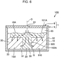
- Fig. 6 is a partial vertical cross-sectional view of a second embodiment of the liquid absorbing structure according to the present invention.
- This embodiment is the same as the first embodiment except for the shapes of the regions where the first liquid absorber and the second liquid absorber are disposed.
- the region where a first ink absorber 10A is disposed has portions having different shapes in the direction of the central axis O of the ink supply port 81 as seen in the cross-section taken along the central axis O of the ink supply port 81.
- the region where the first ink absorber 10A is disposed has a large width (diameter) in and near the surface of the ink absorber 10, that is, at a shallow position, and the region where the first ink absorber 10A is disposed has a small width (diameter) below this position.
- the region where the first ink absorber 10A is disposed includes a first region 101A having a large width (diameter) and a second region 102A disposed nearer to a bottom 91 than the first region 101A and having a smaller width (diameter) than the first region 101A.
- a second ink absorber 10B is disposed around and in close contact with the first region 101A and the second region 102A.
- the first region 101A and the second region 102A both have a constant width (diameter) in the direction of the central axis O.
- the first region 101A does not reach the side walls 92.
- the ink Q permeability in the directions (left and right directions in the figure) intersecting the central axis O can be further improved at a shallow position of the ink absorber storage container 1. Therefore, the ink Q permeates vertically downward after the ink Q permeates throughout the first ink absorber 10A in the first region 101A. The ink Q permeability can thus be improved in view of the entire ink absorber 10.
- the region where the first ink absorber 10A (first liquid absorber) is disposed thus has portions having different shapes in the direction of the central axis O of the ink supply port 81 (supply port) as seen in the cross-section taken along the central axis O of the ink supply port 81.
- the ink Q permeability in the directions intersecting the depth direction of the ink absorber storage container 1 can be adjusted by setting the shape of the region where the first ink absorber 10A is disposed in the cross-section as described above. As a result, the ink Q permeability can be adjusted in view of the entire ink absorber 10.
- Fig. 7 is a partial vertical cross-sectional view of a third embodiment of the liquid absorbing structure according to the present invention.
- This embodiment is the same as the first embodiment except for the shapes of the regions where the first liquid absorber and the second liquid absorber are disposed.
- first regions 101A alternate with second regions 101B in the direction of the central axis O of the ink supply port 81.
- the first region 101A, the second region 101B, the first region 101A, the second region 101B, and the first region 101A are disposed sequentially from the ink supply port 81 side.
- the advantageous effect described in the second embodiment is obtained by disposing the first region 101A adjacent to the ink supply port 81, that is, on the surface.
- the ink Q permeability in the directions (left and right directions in the figure) intersecting the central axis O can be further improved near the bottom 91 by disposing the first region 101A in contact with the bottom 91.
- the ink Q permeability in the directions (left and right directions in the figure) intersecting the central axis O can be further improved in a region in the middle in the depth direction by disposing the first region 101A in the middle in the depth direction.
- the ink Q permeability can be further improved in view of the entire ink absorber 10.
- Fig. 8 is a partial vertical cross-sectional view of a fourth embodiment of the liquid absorbing structure according to the present invention.
- This embodiment is the same as the first embodiment except for the shapes of the regions where the first liquid absorber and the second liquid absorber are disposed.
- This embodiment is the same as the first embodiment except for the shapes of the regions where the first liquid absorber and the second liquid absorber are disposed.
- inner side faces 921 of the ink absorber storage container 1 each have a distant portion 921A distant from the central axis O of the ink supply port 81 and a close portion 921B close to the central axis O.
- the close portion 921B is a portion located at the shortest distance from the central axis O, and the other portion is the distant portion 921A.
- the region where a first ink absorber 10A (first liquid absorber) is disposed has protrusions 103A (portions) protruding toward the distant portions 921A.
- the protrusions 103A protrude toward four corner portions being the distant portions 921A. According to this configuration, the ink Q can more assuredly permeate the second ink absorber 10B located near the distant portions 921B (corner portions).
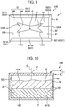
- Fig. 10 is a partial vertical cross-sectional view of a sixth embodiment of the liquid absorbing structure according to the present invention.
- This embodiment is the same as the first embodiment except for the shapes of the regions where the first liquid absorber and the second liquid absorber are disposed.
- a first ink absorber 10A (first liquid absorber) is disposed (on the shallow side) proximal to the ink supply port 81 (supply port), and a second ink absorber 10B (second liquid absorber) is disposed (on the deep side) distal to the ink supply port 81 (supply port).
- the second ink absorber 10B and the first ink absorber 10A are sequentially stacked from below. According to this configuration, the ink Q can readily permeate in the depth direction of the ink absorber storage container 1 and the ink Q can more effectively permeate the entire ink absorber 10.
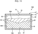
- Fig. 11 is a partial vertical cross-sectional view of a seventh embodiment of the liquid absorbing structure according to the present invention.
- the seventh embodiment of the liquid absorbing structure according to the present invention will be described below with reference to this figure.
- the different points from the above-described embodiment will be mainly described, and the same points will not be described.
- This embodiment is the same as the sixth embodiment except for the shapes of the regions where the first liquid absorber and the second liquid absorber are disposed.
- the amount of protrusion is the largest at the central axis O, and the amount of protrusion decreases away from the central axis O.
- the ink Q can readily permeate in the depth direction of the ink absorber storage container 1 and the ink Q can more effectively permeate the entire ink absorber 10.
- the liquid absorbing structure of the present invention may be a combination of any two or more of the configurations (features) of the embodiments.
- 1 Ink absorber storage container 10 Ink absorber, 10A First ink absorber, 10B Second ink absorber, 101A First region, 101B Second region, 102A Second region, 103A Protrusion, 100 Liquid absorbing structure, 200 Printing apparatus, 201 Ink ejecting head, 201a Nozzle, 202 Capping unit, 203 Tube, 203a Discharge port, 204 Roller pump, 204a Roller unit, 204b Holding unit, 20 Fiber, 30 Water-absorbent resin, 8 Lid body, 81 Ink supply port, 9 Container body, 91 Bottom, 910 Bottom face, 92 Side wall, 920 Inner side face, 921 Inner side face, 921A Portion, 93 Storage space, 94 Upper opening, 95 Void, O Central axis, Q Ink
Landscapes
- Engineering & Computer Science (AREA)
- Environmental & Geological Engineering (AREA)
- Textile Engineering (AREA)
- Chemical & Material Sciences (AREA)
- Materials Engineering (AREA)
- Ink Jet (AREA)
Abstract
Description
- The present invention relates to a liquid absorbing structure and a liquid droplet ejecting apparatus.
- For example, ink jet printers normally generate waste ink during head cleaning for preventing decreases in print quality caused by ink clogging or during ink charging after ink cartridge exchange. To avoid undesired accumulation of such waste ink in the printer internal system or the like, ink jet printers include a liquid absorber (ink absorber) for absorbing waste ink.
- In the related art, a liquid absorber (ink absorber) contains a natural cellulose fiber and/or a synthetic fiber and a heat-fusible substance (see, for example, PTL 1).
- However, such a known liquid absorber (ink absorber) has low ink permeability so that it fails to absorb a sufficient amount of waste ink or fails to rapidly absorb waste ink.
- PTL 1: Japanese Patent No.
3536870 - The present invention is directed to a liquid absorbing structure and a liquid droplet ejecting apparatus that have improved ink absorption properties.
- The present invention is made to solve at least some of the above-described problems and accomplished as described below.
- A liquid absorbing structure according to the present invention includes:
- a liquid absorber having a fiber and a water-absorbent resin capable of absorbing liquid; and
- a container having a supply port through which the liquid is supplied and a storage space in which the liquid absorber is stored.
- The liquid absorber contains a first liquid absorber and a second liquid absorber that are different in density of at least one of the fiber and the water-absorbent resin.
- The first liquid absorber and the second liquid absorber are disposed at different positions in the container.
- A liquid droplet ejecting apparatus according to the present invention includes a collecting unit that collects waste ink.
- The liquid absorbing structure according to the present invention is installed in the collecting unit.
-
- [
Fig. 1] Fig. 1 is a partial vertical cross-sectional view that illustrates a sequence of operating states (example) of a first embodiment of a liquid absorbing structure according to the present invention. - [
Fig. 2] Fig. 2 is an enlarged view that illustrates an example form (small piece) of the liquid absorber shown inFig. 1 . - [
Fig. 3] Fig. 3 is an enlarged view that illustrates an example form (fibrillated fiber) of the liquid absorber shown inFig. 1 . - [
Fig. 4] Fig. 4 is a view of the inside of the liquid absorber storage container of the liquid absorbing structure shown inFig. 1 as seen from the supply port. - [
Fig. 5] Fig. 5 is a partial vertical cross-sectional view of the liquid absorbing structure shown inFig. 4 . - [
Fig. 6] Fig. 6 is a partial vertical cross-sectional view of a second embodiment of the liquid absorbing structure according to the present invention. - [
Fig. 7] Fig. 7 is a partial vertical cross-sectional view of a third embodiment of the liquid absorbing structure according to the present invention. - [
Fig. 8] Fig. 8 is a partial vertical cross-sectional view of a fourth embodiment of the liquid absorbing structure according to the present invention. - [
Fig. 9] Fig. 9 is a view of the inside of a fifth embodiment of the liquid absorbing structure according to the present invention as seen from the supply port. - [
Fig. 10] Fig. 10 is a partial vertical cross-sectional view of a sixth embodiment of the liquid absorbing structure according to the present invention. - [
Fig. 11] Fig. 11 is a partial vertical cross-sectional view of a seventh embodiment of the liquid absorbing structure according to the present invention. - A liquid absorbing structure and a liquid droplet ejecting apparatus according to the present invention will be specifically described below on the basis of preferred embodiments shown in the appended drawings.
-
Fig. 1 is a partial vertical cross-sectional view that illustrates a sequence of operating states (example) of a first embodiment of the liquid absorbing structure according to the present invention.Fig. 2 is an enlarged view that illustrates an example form (small piece) of the liquid absorber shown inFig. 1 .Fig. 3 is an enlarged view that illustrates an example form (fibrillated fiber) of the liquid absorber shown inFig. 1 .Fig. 4 is a view of the inside of the liquid absorber storage container of the liquid absorbing structure shown inFig. 1 as seen from the supply port.Fig. 5 is a partial vertical cross-sectional view of the liquid absorbing structure shown inFig. 4 . - Hereinafter, the upper side and the lower side in
Fig. 1 andFig. 5 (the same applies toFig. 6 to Fig. 8 ,Fig. 10 , andFig. 11 ) are respectively referred to as "upper (or above)" and "lower (or below)" for convenience of description. - As illustrated in
Fig. 1 , a liquid absorbingstructure 100 according to the present invention includes: an ink absorber 10 (liquid absorber) having afiber 20 and a water-absorbent resin 30 capable of absorbing ink Q (liquid); and an ink absorber storage container 1 (container) having an ink supply port 81 (supply port) through which the ink Q (liquid) is supplied and astorage space 93 in which the ink absorber 10 (liquid absorber) is stored. The ink absorber 10 (liquid absorber) contains afirst ink absorber 10A (first liquid absorber) and a second ink absorber 10B (second liquid absorber) which are different in density of at least one of thefiber 20 and the water-absorbent resin 30. The first ink absorber 10A (first liquid absorber) and the second ink absorber 10B (second liquid absorber) are disposed at different positions in the inkabsorber storage container 1. - The first ink absorber 10A and the second ink absorber 10B can be thus disposed in the ink
absorber storage container 1 according to their ink Q absorption properties. For example, the first ink absorber 10A in which the density of thefiber 20 is low has high permeability (diffusivity), whereas the second ink absorber 10B in which the density of the water-absorbent resin 30 is low exhibits high water absorbency (water retention). In the present invention, according to these properties, for example, the first ink absorber 10A having high permeability can be disposed at a position (proximal to the ink supply port 81) such that the ink Q first comes into contact with the first ink absorber 10A, and the second ink absorber 10B exhibiting high water absorbency (water retention) can be disposed around thefirst ink absorber 10A (distal to the ink supply port 81). According to this configuration, the ink Q supplied into the inkabsorber storage container 1 first rapidly permeates the entire first ink absorber 10A and is then effectively absorbed into thesecond ink absorber 10B. The present invention accordingly enables rapid and effective liquid absorption, that is, can improve the ink Q absorption properties. - The term "water absorption" as used herein refers to absorption of a water-based ink in which a color material is dissolved in an aqueous solvent, a solvent-based ink in which a binder is dissolved in a solvent, a UV-curable ink in which a binder is dissolved in a liquid monomer curable by UV irradiation, an ink such as latex ink in which a binder is dispersed in a dispersion medium, and other liquids (e.g., excreta, industrial waste liquid).
- A printing apparatus 200 (liquid droplet ejecting apparatus) illustrated in
Fig. 1 is, for example, an ink jet color printer. Theprinting apparatus 200 includes anink ejecting head 201 which ejects the ink Q, acapping unit 202 which prevents clogging of anozzle 201a of theink ejecting head 201, atube 203 which connects thecapping unit 202 and the liquid absorbingstructure 100, aroller pump 204 which feeds the ink Q from thecapping unit 202 to theliquid absorbing structure 100, and acollecting unit 205. - The
ink ejecting head 201 hasmultiple nozzles 201a from which the ink Q is ejected downward. Theink ejecting head 201 ejects the ink Q while moving relative to a recording medium (not illustrated), such as a PPC sheet, whereby printing is performed (see theink ejecting head 201 drawn with long dashed double-dotted lines inFig. 1 ). - The
capping unit 202 collectively sucks thenozzles 201a by means of the operation of theroller pump 204 when theink ejecting head 201 is in the standby position. This prevents clogging of thenozzles 201a. - The
tube 203 is such that the ink Q sucked via thecapping unit 202 passes through thetube 203 toward the liquid absorbingstructure 100. Thetube 203 has flexibility. - The
roller pump 204 is disposed in the middle of thetube 203 and includes aroller unit 204a and aholding unit 204b which holds the middle of thetube 203 between theholding unit 204b and theroller unit 204a. As theroller unit 204a rotates, a suction force is generated in thecapping unit 202 via thetube 203. As theroller unit 204a continuously rotates, the ink Q attached to thenozzle 201a can be fed to thecollecting unit 205. - The liquid droplet ejecting apparatus (printing apparatus 200) according to the present invention includes the
collecting unit 205 which collects waste ink Q, and the liquid absorbingstructure 100 is installed in thecollecting unit 205. The ink Q is absorbed into theliquid absorbing structure 100 as waste liquid. The ink Q includes various colors of ink. According to this configuration, the liquid absorbingstructure 100 can absorb the ink Q while enjoying the advantages described above. - As illustrated in
Fig. 1 , theliquid absorbing structure 100 includes the inkabsorber storage container 1 and theink absorber 10 used to absorb the ink Q. Theliquid absorbing structure 100 is detachably attached to theprinting apparatus 200 and used to absorb waste ink Q as described above while being detachably attached to theprinting apparatus 200. Theliquid absorbing structure 100 can thus be used as a so-called "waste liquid tank (waste ink tank)". When the amount of the ink Q absorbed into theliquid absorbing structure 100 reaches the limit, theliquid absorbing structure 100 can be replaced by a new (unused)liquid absorbing structure 100. Whether the amount of the ink Q absorbed into theliquid absorbing structure 100 reaches the limit is detected by a detector (not illustrated) in theprinting apparatus 200. When the amount of the ink Q absorbed into theliquid absorbing structure 100 reaches the limit, the notice is given by, for example, a notification unit (not illustrated) such as a monitor installed in theprinting apparatus 200. - The ink absorber 10 (liquid absorber) is used to absorb the ink Q in the ink
absorber storage container 1. As illustrated inFig. 2 and Fig. 3 , theink absorber 10 includes thefiber 20 and the water-absorbent resin 30 attached to (carried on) thefiber 20. It is noted that strands of thefiber 20 are preferably bonded to each other via a binder (not illustrated). - When the ink Q is applied to the
ink absorber 10, thefiber 20 once holds the ink Q and then can efficiently feed the ink Q to the water-absorbent resin 30, which can improve the ink Q absorption properties of theentire ink absorber 10. In general, fiber (particularly fiber from used paper) such as cellulose fiber is cheaper than the water-absorbent resin 30 and advantageous in low costs for manufacturing theink absorber 10. Fiber from used paper is suitably used as thefiber 20, which is advantageous in, for example, reduction of waste and effective use of resources. - Examples of the
fiber 20 include synthetic resin fibers, such as polyester fibers and polyamide fibers; natural resin fibers, such as cellulose fibers, keratin fibers, and fibroin fibers; and chemically modified fibers thereof. These fibers can be used alone or in a mixture as desired. Thefiber 20 is preferably composed mainly of cellulose fiber and more preferably composed substantially entirely of cellulose fiber. - Since cellulose is a material having suitable hydrophilicity, the ink Q applied to the
ink absorber 10 can readily get out of the particularly high fluidity state (e.g., the state of having a viscosity of 10 mPa·s or lower), and the once incorporated ink Q can be successfully fed to the water-absorbent resin 30 (can permeate the water-absorbent resin 30). As a result, theentire ink absorber 10 exhibits particularly high ink Q permeability (absorption properties). Since cellulose is normally highly compatible with the water-absorbent resin 30, the water-absorbent resin 30 can be successfully carried on the surface of thefiber 20. Cellulose fiber is a renewable natural material and cheap and easily available among various fibers. Cellulose fiber is thus advantageous in, for example, low production costs and stable production of theink absorber 10, and low environmental burden. - The term cellulose fiber as used herein refers to any fibrous material composed mainly of cellulose (cellulose in a narrow sense) as a compound and includes, in addition to cellulose (cellulose in a narrow sense), hemicellulose and lignin.
- The
fiber 20 in theink absorber 10 is in the form of small piece (seeFig. 2 ) in the following description, but thefiber 20 may be, for example, in a cottony form (seeFig. 3 ) or in a sheet form. - The entire length (the length in the longitudinal direction) of the small piece is, for example, preferably 0.5 mm or more and 500 mm or less, more preferably 1 mm or more and 100 mm or less, and still more preferably 2 mm or more and 30 mm or less, although the entire length depends on the shape and size of the ink absorber storage container 1 (see
Fig. 2 ). - The width (the length in the transverse direction) of the small piece is, for example, preferably 0.1 mm or more and 100 mm or less, more preferably 0.3 mm or more and 50 mm or less, and still more preferably 1 mm or more and 20 mm or less, although the width depends on the shape and size of the ink absorber storage container 1 (see
Fig. 2 ). - The aspect ratio of the entire length to the width is preferably 1.0 or more and 200 or less, and more preferably 1.0 or more and 30 or less. The thickness of the small piece is, for example, preferably 0.05 m or more and 2 mm or less, and more preferably 0.1 mm or more and 1 mm or less (see
Fig. 2 ). - For example, used paper may be used as a raw material of the
fiber 20. The use of used paper is preferred in view of the advantageous effects as described above and conservation of resources. When used paper is used as a raw material of thefiber 20, the used paper may be used without any processing, or shredded paper obtained by shredding used paper or fibrillated fiber obtained by fibrillating used paper may be used. For example, a sheet-shapedfiber base material 30 cm in length, 22 cm in width, and 0.1 mm in thickness can be used as used paper. - The average length of the
fiber 20 is preferably, but not necessarily, 0.1 mm or more and 5 mm or less, and more preferably 0.2 mm or more and 3 mm or less. The average width (diameter) of thefiber 20 is preferably, but not necessarily, 0.5 µm or more and 200 µm or less, and more preferably 1.0 µm or more and 100 µm or less. The average aspect ratio (the ratio of the average length to the average width) of thefiber 20 is preferably, but not necessarily, 10 or more and 1000 or less, and more preferably 15 or more and 500 or less. - Having the average aspect ratio in such a range, the
fiber 20 can successfully carry the water-absorbent resin 30, hold the ink Q, and feed the ink Q to the water-absorbent resin 30. As a result, theentire ink absorber 10 exhibits high ink Q permeability (absorption properties). - The water-
absorbent resin 30 is any resin having water absorbency. Examples of the water-absorbent resin include, but are not limited to, carboxymethyl cellulose, polyacrylic acid, polyacrylamide, starch-acrylic acid graft copolymer, hydrolyzed starch-acrylonitrile graft copolymer, vinyl acetate-acrylic acid ester copolymer, isobutylene-maleic acid copolymer, hydrolyzed acrylonitrile copolymers or acrylamide copolymers, polyethylene oxide, polysulfonic acid compounds, polyglutamic acid, salts (neutralized products) thereof, and cross-linked products. The term water absorbency refers to a function of having hydrophilicity and retaining water. Many of the water-absorbent resin 30 are gelled when absorbing water. - In particular, the water-
absorbent resin 30 is preferably a resin having a functional group in its side chain. Examples of the functional group include an acid group, a hydroxyl group, an epoxy group, and an amino group. - In particular, the water-
absorbent resin 30 is preferably a resin having an acid group in its side chain, and more preferably a resin having a carboxyl group in its side chain. - Examples of the carboxyl group-containing unit that constitutes the water-
absorbent resin 30 include units derived from monomers, such as acrylic acid, methacrylic acid, itaconic acid, maleic acid, crotonic acid, fumaric acid, sorbic acid, cinnamic acid, anhydrides thereof, and salts thereof. - When the water-
absorbent resin 30 having acid groups in side chains is present, the proportion of acid groups neutralized to form salts among the acid groups contained in the water-absorbent resin 30 is preferably 30 mol% or more and 100 mol% or less, more preferably 50 mol% or more and 95 mol% or less, still more preferably 60 mol% or more and 90 mol% or less, and yet still more preferably 70 mol% or more and 80 mol% or less. At such a proportion, the water-absorbent resin 30 (ink absorber 10) has high ink Q absorbency (water retention). - Examples of the neutralized salt include, but are not limited to, alkali metal salts, such as sodium salts, potassium salts, and lithium salts; and salts of nitrogen-containing basic substances, such as ammonia. The neutralized salt is preferably a sodium salt. With such a salt, the water-absorbent resin 30 (ink absorber 10) has high ink Q absorbency (water retention).
- The water-
absorbent resin 30 having acid groups in side chains is preferred because electrostatic repulsion between acid groups occurs during ink absorption to accelerate the absorption rate. When the acid groups are neutralized, the ink Q tends to be absorbed into the water-absorbent resin 30 due to osmotic pressure. - The water-
absorbent resin 30 may have a structural unit with no acid group. Examples of such a structural unit include hydrophilic structural units, hydrophobic structural units, structural units that serve as polymerization cross-linkers. - Examples of the hydrophilic structural units include structural units derived from nonionic compounds, such as acrylamide, methacrylamide, N-ethyl(meth)acrylamide, N-n-propyl(meth)acrylamide, N-isopropyl(meth)acrylamide, N,N-dimethyl(meth)acrylamide, 2-hydroxyethyl(meth)acrylate, 2-hydroxypropyl(meth)acrylate, methoxy polyethylene glycol (meth)acrylate, polyethylene glycol mono(meth)acrylate, N-vinylpyrrolidone, N-acryloylpiperidine, and N-acryloylpyrrolidine.
- Examples of the hydrophobic structural units include structural units derived from compounds, such as (meth)acrylonitrile, styrene, vinyl chloride, butadiene, isobutene, ethylene, propylene, stearyl (meth)acrylate, and lauryl (meth)acrylate.
- Examples of the structural units that serve as polymerization cross-linkers include structural units derived from diethylene glycol diacrylate, N,N'-methylenebisacrylamide, polyethylene glycol diacrylate, polypropylene glycol diacrylate, trimethylolpropane diallyl ether, trimethylolpropane triacrylate, allyl glycidyl ether, pentaerythritol triallyl ether, pentaerythritol diacrylate monostearate, bisphenol diacrylate, isocyanuric acid diacrylate, tetraallyloxyethane, diallyloxyacetate, and the like.
- The water-
absorbent resin 30 preferably contains a polyacrylic acid salt copolymer or a polyacrylic acid polymerized/cross-linked product. This provides, for example, advantages, such as high ink Q absorbency (water retention) and low manufacturing costs. - In the polyacrylic acid polymerized/cross-linked product, the proportion of carboxyl group-containing structural units in all structural units that constitute molecular chains is preferably 50 mol% or higher, more preferably 80 mol% or higher, and still more preferably 90 mol% or higher.
- If the proportion of carboxyl group-containing structural units is too low, it may be difficult to sufficiently improve the ink Q absorption performance.
- The carboxyl groups in the polyacrylic acid polymerized/cross-linked product are preferably partially neutralized (subjected to partial neutralization) to form salts.
- The proportion of neutralized carboxyl groups in all carboxyl groups in the polyacrylic acid polymerized/cross-linked product is preferably 30 mol% or more and 99 mol% or less, more preferably 50 mol% or more and 99 mol% or less, and still more preferably 70 mol% or more and 99 mol% or less.
- The water-
absorbent resin 30 may have a structure formed by cross-linking using a cross-linker other than the above-described polymerization cross-linkers. - When the water-
absorbent resin 30 is a resin having an acid group, the cross-linker is preferably, for example, a compound having multiple functional groups reactive with the acid group. - When the water-
absorbent resin 30 is a resin having a functional group reactive with an acid group, the cross-linker is preferably a compound having, in the molecule, multiple functional groups reactive with the acid group. - Examples of the compound (cross-linker) having multiple functional groups reactive with the acid group include glycidyl ether compounds, such as ethylene glycol diglycidyl ether, trimethylolpropane triglycidyl ether, (poly)glycerol polyglycidyl ether, diglycerol polyglycidyl ether, and propylene glycol diglycidyl ether; polyhydric alcohols, such as (poly)glycerol, (poly)ethylene glycol, propylene glycol, 1,3-propanediol, polyoxyethylene glycol, triethylene glycol, tetraethylene glycol, diethanolamine, and triethanolamine; and polyvalent amines, such as ethylenediamine, diethylenediamine, polyethyleneimine, and hexamethylenediamine. In addition, for example, multivalent ions, such as zinc, calcium, magnesium, and aluminum, can also be preferably used because they react with the acid group of the water-
absorbent resin 30 so as to function as a cross-linker. - The water-
absorbent resin 30 may be in any form, such as a scale form, a needle form, a fiber form, or a particle form, but preferably in a particle form. When the water-absorbent resin 30 is in a particle form, it is easy to ensure ink Q permeability. In addition, the water-absorbent resin 30 can be successfully carried on thefiber 20. The average particle size of the particles is preferably 50 µm or more and 800 µm or less, more preferably 100 µm or more and 600 µm or less, and still more preferably 200 µm or more and 500 µm or less. - The
ink absorber 10 may contain components (other components) other than the above-described components. Examples of such components include surfactants, lubricants, defoamers, fillers, anti-blocking agents, ultraviolet absorbers, coloring agents such as pigments and dyes, flame retardants, and fluidity improvers. - As illustrated in
Fig. 1 , the inkabsorber storage container 1 includes acontainer body 9 having thestorage space 93 in which theink absorber 10 is stored, and alid body 8 detachably attached to thecontainer body 9. - The
container body 9 has a box shape having a bottom (bottom plate) 91 with, for example, a rectangular shape in plan view, and fourside walls 92 standing upward from the respective sides (edges) of the bottom 91. Theink absorber 10 can be stored in thestorage space 93 surrounded by the bottom 91 and the fourside walls 92. Hereinafter, a face of the bottom 91 that faces thestorage space 93 is referred to as abottom face 910, and faces of theside walls 92 that face thestorage space 93 are referred to as inner side faces 920. Thebottom face 910 and the inner side faces 920 define thestorage space 93. - The
container body 9 is not limited to a container body having the bottom 91 with a rectangular shape in plan view, and may be, for example, a cylindrical container body having a bottom 91 with a circular shape in plan view. - The ratio V2/V1 of V2 to V1 where V1 represents the volume of the container body 9 (storage space 93) and V2 represents the total volume of the
ink absorber 10 before absorption of the ink Q (before water absorption) is preferably 0.1 or more and 0.7 or less, and more preferably 0.2 or more and 0.7 or less (seeFig. 1 ). At such a ratio, a void 95 is generated above theink absorber 10 in thecontainer body 9. Theink absorber 10 once expands (swells) after absorbing the ink Q. The void 95 functions as a buffer when theink absorber 10 expands, and theink absorber 10 can thus absorb the ink Q well. - In this embodiment, the
container body 9 is hard, that is, has shape retention to such an extent that the volume V1 does not change by, for example, 10% or more when thecontainer body 9 experiences an internal pressure or external force. Having this property, thecontainer body 9 can maintain its shape even when theink absorber 10 expands after absorbing the ink Q and thecontainer body 9 experiences an internal force from theink absorber 10. This configuration stabilizes the installation condition of thecontainer body 9 in theprinting apparatus 200 and allows theink absorber 10 to stably absorb the ink Q. - The
container body 9 is made of any material that the ink Q does not permeate. Examples of such a material of thecontainer body 9 include various resin materials, such as cyclic polyolefins and polycarbonates. Examples of the material of thecontainer body 9 include, in addition to the above-described various resin materials, various metal materials, such as aluminum and stainless steel. - The
container body 9 is not necessarily hard and may be flexible (soft), that is, such that the volume V1 changes by, for example, 10% or more when thecontainer body 9 experiences an internal pressure or external force. - The
container body 9 may be either transparent (including semi-transparent) so as to have internal visibility or may be opaque. Preferably, thecontainer body 9 and thelid body 8 described below at least partially have internal visibility. - As described above, the
liquid absorbing structure 100 includes thelid body 8. As illustrate inFig. 1 , thelid body 8 has a plate shape and can be fitted into anupper opening 94 of thecontainer body 9. This fitting can seal theupper opening 94 in a liquid tight manner. This configuration can prevent the ink Q from spreading outside, for example, even if the ink Q discharged and dropping from thetube 203 strikes theink absorber 10 and bounces up. Therefore, the ink Q can be prevented from adhering to and staining the surroundings of theliquid absorbing structure 100. - The
tube 203 is connected to a central portion of thelid body 8 to form an ink supply port (connection port) 81 through which the ink Q is supplied into thestorage space 93. Theink supply port 81 is composed of a through-hole that passes through thelid body 8 in the thickness direction. Thetube 203 can be connected to thelid body 8 such that a downstream end (lower end) of thetube 203 is inserted into the ink supply port 81 (through-hole). At this time, a discharge port (opening) 203a of thetube 203 faces downward. Theink supply port 81 may be formed at a position distant from a central portion of thelid body 8. - The
lid body 8 may have ink absorbency to absorb the ink Q or may have liquid repellency to repel the ink Q. - The thickness of the
lid body 8 is preferably, but not necessarily, for example, 1 mm or more and 20 mm or less, and more preferably 8 mm or more and 10 mm or less. Thelid body 8 is not limited to a plate-shaped lid body having a thickness in this range, and may be a film-shaped (sheet-shaped) lid body thinner than this thickness. In this case, the thickness of thelid body 8 is preferably, but not necessarily, for example, 10 µm or more and less than 1 mm. - The
lid body 8 preferably has water vapor permeability. With thelid body 8 having this property, water evaporated from the absorbed ink Q can permeate thelid body 8 to the outside. This can increase the amount of the ink Q that can be absorbed by theink absorber 10. - The water vapor transmission rate of the
lid body 8 is preferably 1.0 g/m2/day (40°C, 90 %RH) or higher and 5000 g/m2/day (40°C, 90 %RH) or lower, and more preferably 2.0 g/m2/day (40°C, 90 %RH) or higher and 2000 g/m2/day (40°C, 90 %RH) or lower. At such a rate, the above-described advantageous effect can be obtained more assuredly. - The materials of the
container body 9 and thelid body 8 are not limited and, for example, various resin materials can be suitably used. Examples of the resin materials include various thermoplastic resins, and various curable resins, such as thermosetting resins and photocurable resins. Specific examples include polyolefins, such as polyethylene, polypropylene, and ethylene-propylene copolymer; polyesters, such as polyvinyl chloride, polystyrene, polyamide, polyimide, polycarbonate, poly-(4-methylpentene-1), ionomer, acrylic resin, polymethyl methacrylate, acrylonitrile-butadiene-styrene copolymer (ABS resin), acrylonitrile-styrene copolymer (AS resin), butadiene-styrene copolymer, polyethylene terephthalate (PET), and polybutylene terephthalate (PBT); polyether, polyether ketone (PEK), polyether ether ketone (PEEK), polyetherimide, polyacetal (POM), polyphenylene oxide, polysulfone, polyether sulfone, polyphenylene sulfide, polyarylate, aromatic polyester (liquid crystal polymer), polytetrafluoroethylene, polyvinylidene difluoride, other fluorocarbon resins, epoxy resin, phenol resin, urea resin, melamine resin, silicone resin, and polyurethane; copolymers, blends, polymer alloys, and the like containing these as main components. These resin materials can be used alone or in combination of two or more. - The
first ink absorber 10A is disposed at a position such that the ink Q (liquid) supplied through theink supply port 81 first comes into contact with thefirst ink absorber 10A, and thesecond ink absorber 10B is disposed at a position such that the ink Q comes into contact with thesecond ink absorber 10B after contact with thefirst ink absorber 10A. - Specifically, as illustrated in
Fig. 4 , thefirst ink absorber 10A is disposed at a position so as to overlap theink supply port 81, that is, directly under theink supply port 81, as seen from the ink supply port 81 (in plan view). Thefirst ink absorber 10A has a larger size than the opening of theink supply port 81 as seen from theink supply port 81, and thefirst ink absorber 10A is large enough to encompass theink supply port 81. Thus, the ink Q dropped from theink supply port 81 can first come into contact with thefirst ink absorber 10A more assuredly. - In the structure illustrated in the figure, the
first ink absorber 10A has a circular shape as seen from theink supply port 81. Thefirst ink absorber 10A is not limited to a circular shape, and may have a shape, such as an elliptical shape, a rectangular shape, a polygonal shape, or a star shape. - As illustrated in
Fig. 5 , thefirst ink absorber 10A is disposed so as to extend along a central axis O of theink supply port 81 as seen in the cross-section taken along the central axis O. Thefirst ink absorber 10A is disposed in contact with the bottom 91. - In other words, the ink absorber storage container 1 (container) has the
bottom face 910 and the inner side faces 920 which define thestorage space 93, and thefirst ink absorber 10A (first liquid absorber) is in contact with thebottom face 910 of the ink absorber storage container 1 (container). According to this configuration, the ink supplied to the inkabsorber storage container 1 can readily permeate to the bottom face of the inkabsorber storage container 1, as described below. - The
second ink absorber 10B is disposed around thefirst ink absorber 10A and disposed in contact with theside walls 92 as illustrated inFig. 4 and in contact with the bottom 91 as illustrated inFig. 5 . - In plan view as seen from the ink supply port 81 (supply port), the
first ink absorber 10A (first liquid absorber) is thus disposed at a position so as to overlap the ink supply port 81 (supply port), and thesecond ink absorber 10B (second liquid absorber) is disposed around thefirst ink absorber 10A (first liquid absorber). According to this configuration, the ink Q supplied into the inkabsorber storage container 1 can first come into contact with the first liquid absorber. Therefore, liquid can be absorbed rapidly and effectively. - The
second ink absorber 10B is not necessarily in contact with theside walls 92. In other words, a void may be formed between thesecond ink absorber 10B and theside walls 92. The void can thus function as a relief area when thesecond ink absorber 10B absorbs the ink Q and swells. - As described above, the
first ink absorber 10A and thesecond ink absorber 10B disposed in this manner are different in density of at least one of thefiber 20 and the water-absorbent resin 30. As the density of thefiber 20 decreases, the ink Q permeability increases. As the density of the water-absorbent resin 30 decreases, the ink Q absorbency (water retention) increases. Thefirst ink absorber 10A and thesecond ink absorber 10B are accordingly different in ink Q absorption properties. - In this embodiment, the density of the
fiber 20 of thefirst ink absorber 10A (first liquid absorber) is lower than the density of thefiber 20 of thesecond ink absorber 10B. The ink Q can thus sufficiently ensure gaps between strands of thefiber 20 in thefirst ink absorber 10A, and the ink Q easily permeates thefirst ink absorber 10A. In other words, thefirst ink absorber 10A has higher ink Q permeability than thesecond ink absorber 10B. - The ratio A1/A2 where A1 represents the density of the
fiber 20 in thefirst ink absorber 10A (first liquid absorber) and A2 represents the density of thefiber 20 in thesecond ink absorber 10B (second liquid absorber) is preferably 0.1 or more and 0.9 or less, and more preferably 0.2 or more and 0.8 or less. At such a ratio, thefirst ink absorber 10A has high permeability more assuredly. - If the ratio A1/A2 is too small, the density of the
fiber 20 in thesecond ink absorber 10B is relatively high, and the permeability of thesecond ink absorber 10B tents to be low. If the ratio A1/A2 is too large, the advantageous effect from providing a difference in density of thefiber 20 is not obtained. - In this embodiment, the density of the water-
absorbent resin 30 of thefirst ink absorber 10A (first liquid absorber) is lower than the density of the water-absorbent resin 30 of thesecond ink absorber 10B (second liquid absorber). Thefirst ink absorber 10A thus exhibits lower expansion coefficient than thesecond ink absorber 10B when absorbing the ink Q. This prevents the expanded water-absorbent resin 30 from inhibiting permeation of the ink Q. - The ratio B1/B2 where B1 represents the density of the water-
absorbent resin 30 in thefirst ink absorber 10A (first liquid absorber) and B2 represents the density of the water-absorbent resin 30 in thesecond ink absorber 10B (second liquid absorber) is preferably 0 or more and 0.9 or less, and more preferably 0.1 or more and 0.8 or less. At such a ratio, the above-described advantageous effect can be obtained more significantly. - If the ratio B1/B2 is too small, the amount of the water-
absorbent resin 30 of thesecond ink absorber 10B tends to be too high, and the permeability of thesecond ink absorber 10B tents to be too low. If the ratio B1/B2 is too large, the permeability of thefirst ink absorber 10A tents to be low. - When at least one of the
fiber 20 and the water-absorbent resin 30 is different, the advantageous effects of the present invention can be obtained. When thefiber 20 and the water-absorbent resin 30 are both different, the advantageous effects of the present invention are obtained more significantly due to synergistic effects. - Since the density of the
fiber 20 of thesecond ink absorber 10B is larger than that of thefirst ink absorber 10A, relatively narrow gaps are formed between strands of thefiber 20 of thesecond ink absorber 10B, which can prevent the ink Q from having excessively high fluidity. The ink Q that has once permeated thesecond ink absorber 10B is thus unlikely to seep from thesecond ink absorber 10B. - In addition, since the density of the water-
absorbent resin 30 of thesecond ink absorber 10B is larger than that of thefirst ink absorber 10A, the amount of the ink Q absorbed per unit volume of the ink Q is larger in thesecond ink absorber 10B. In combination of this and the foregoing, thesecond ink absorber 10B exhibits high water absorbency (moisture retention). - In this embodiment, as described above, the
first ink absorber 10A having high permeability is disposed at a position such that the ink Q supplied through theink supply port 81 first comes into contact with thefirst ink absorber 10A, and the supplied ink Q readily permeates in the direction of the central axis O and in the directions intersecting the central axis O as indicated by the arrows inFig. 5 . The ink Q transmits thefirst ink absorber 10A to thesecond ink absorber 10B having high water absorbency (moisture retention), whereby the ink Q is absorbed assuredly and prevented from seeping out (leaking out). - In the present invention, the positions at which the
first ink absorber 10A and thesecond ink absorber 10B are disposed can be thus set according to the ink Q (liquid) absorption properties of thefirst ink absorber 10A and thesecond ink absorber 10B. As a result, for example, as described above, the ink Q can permeate the entire ink absorber, while the ink Q can be absorbed into the ink absorber assuredly and prevented from seeping out (leaking out). - When the
fiber 20 of thefirst ink absorber 10A and thefiber 20 of thesecond ink absorber 10B are in the form of small piece as in this embodiment, a difference in density of thefiber 20 can be generated by providing a configuration in which thefirst ink absorber 10A and thesecond ink absorber 10B are the same in packing amount of the small piece but different in density of thefiber 20 of the small piece itself, a configuration in which thefirst ink absorber 10A and thesecond ink absorber 10B are the same in density of thefiber 20 of the small piece but different in packing amount of the small piece, or a configuration in which thefirst ink absorber 10A and thesecond ink absorber 10B are different in packing amount of the small piece and in density itself of thefiber 20 of the small piece. - It is noted that the
first ink absorber 10A and thesecond ink absorber 10B may be different in form of thefiber 20. In other words, one of thefiber 20 of thefirst ink absorber 10A and thefiber 20 of thesecond ink absorber 10B may be a small piece, and the other may be in a cottony form. Even in this case, a difference in density of thefiber 20 can be generated between thefirst ink absorber 10A and thesecond ink absorber 10B. - A difference in density of the
fiber 20 and a difference in density of the water-absorbent resin 30 can also be generated between thefirst ink absorber 10A and thesecond ink absorber 10B by providing a configuration in which the same small piece with the same amount of the water-absorbent resin 30 carried thereon, namely, the same ink absorber, is used but the compression amount (packing amount) of the ink absorber differs. - The
first ink absorber 10A and thesecond ink absorber 10B may both be in a cottony form. In this case, a difference in density of thefiber 20 can be generated between thefirst ink absorber 10A and thesecond ink absorber 10B by providing a configuration in which the type offiber 20 such as the average length or the thickness of thefiber 20 differs, or a configuration in which the bulk density of the same fiber differs. - A difference in density of the water-
absorbent resin 30 can also be generated between thefirst ink absorber 10A and thesecond ink absorber 10B by providing a configuration in which the amount of the water-absorbent resin 30 of the same particle size (same type) carried on thefiber 20 differs, or a configuration in which the same number of particles of the water-absorbent resin 30 having different particle sizes (shapes) are carried on thefiber 20. - The present invention includes all combinations of the configurations in which the density of the
fiber 20 differs and the configurations in which the density of the water-absorbent resin 30 differs, as described above. The forgoing advantageous effects can be obtained by providing only a difference in at least one of the density of thefiber 20 and the density of the water-absorbent resin 30. -
Fig. 6 is a partial vertical cross-sectional view of a second embodiment of the liquid absorbing structure according to the present invention. - The second embodiment of the liquid absorbing structure according to the present invention will be described below with reference to this figure. The different points from the above-described embodiment will be mainly described, and the same points will not be described.
- This embodiment is the same as the first embodiment except for the shapes of the regions where the first liquid absorber and the second liquid absorber are disposed.
- In a
liquid absorbing structure 100 according to this embodiment, as illustrated inFig. 6 , the region where afirst ink absorber 10A is disposed has portions having different shapes in the direction of the central axis O of theink supply port 81 as seen in the cross-section taken along the central axis O of theink supply port 81. - Specifically, the region where the
first ink absorber 10A is disposed has a large width (diameter) in and near the surface of theink absorber 10, that is, at a shallow position, and the region where thefirst ink absorber 10A is disposed has a small width (diameter) below this position. In other words, the region where thefirst ink absorber 10A is disposed includes afirst region 101A having a large width (diameter) and asecond region 102A disposed nearer to a bottom 91 than thefirst region 101A and having a smaller width (diameter) than thefirst region 101A. It is noted that asecond ink absorber 10B is disposed around and in close contact with thefirst region 101A and thesecond region 102A. - The
first region 101A and thesecond region 102A both have a constant width (diameter) in the direction of the central axis O. Thefirst region 101A does not reach theside walls 92. - According to this configuration, the ink Q permeability in the directions (left and right directions in the figure) intersecting the central axis O can be further improved at a shallow position of the ink
absorber storage container 1. Therefore, the ink Q permeates vertically downward after the ink Q permeates throughout thefirst ink absorber 10A in thefirst region 101A. The ink Q permeability can thus be improved in view of theentire ink absorber 10. - The region where the
first ink absorber 10A (first liquid absorber) is disposed thus has portions having different shapes in the direction of the central axis O of the ink supply port 81 (supply port) as seen in the cross-section taken along the central axis O of theink supply port 81. According to this configuration, the ink Q permeability in the directions intersecting the depth direction of the inkabsorber storage container 1 can be adjusted by setting the shape of the region where thefirst ink absorber 10A is disposed in the cross-section as described above. As a result, the ink Q permeability can be adjusted in view of theentire ink absorber 10. -
Fig. 7 is a partial vertical cross-sectional view of a third embodiment of the liquid absorbing structure according to the present invention. - The third embodiment of the liquid absorbing structure according to the present invention will be described below with reference to this figure. The different points from the above-described embodiment will be mainly described, and the same points will not be described.
- This embodiment is the same as the first embodiment except for the shapes of the regions where the first liquid absorber and the second liquid absorber are disposed.
- As illustrated in
Fig. 7 , in this embodiment,first regions 101A alternate withsecond regions 101B in the direction of the central axis O of theink supply port 81. Thefirst region 101A, thesecond region 101B, thefirst region 101A, thesecond region 101B, and thefirst region 101A are disposed sequentially from theink supply port 81 side. - The advantageous effect described in the second embodiment is obtained by disposing the
first region 101A adjacent to theink supply port 81, that is, on the surface. The ink Q permeability in the directions (left and right directions in the figure) intersecting the central axis O can be further improved near the bottom 91 by disposing thefirst region 101A in contact with the bottom 91. Furthermore, the ink Q permeability in the directions (left and right directions in the figure) intersecting the central axis O can be further improved in a region in the middle in the depth direction by disposing thefirst region 101A in the middle in the depth direction. In combination of these effects, the ink Q permeability can be further improved in view of theentire ink absorber 10. -
Fig. 8 is a partial vertical cross-sectional view of a fourth embodiment of the liquid absorbing structure according to the present invention. - The fourth embodiment of the liquid absorbing structure according to the present invention will be described below with reference to this figure. The different points from the above-described embodiment will be mainly described, and the same points will not be described.
- This embodiment is the same as the first embodiment except for the shapes of the regions where the first liquid absorber and the second liquid absorber are disposed.
- As illustrated in
Fig. 8 , the width (diameter) of thesecond region 102A gradually decreases away from theink supply port 81 in this embodiment. According to this configuration, the permeability of thefirst ink absorber 10A in the directions intersecting the depth direction of the inkabsorber storage container 1 gradually decreases with increasing depth. This configuration can further improve the permeability in the depth direction. - In this embodiment, the
second region 102A does not reach the bottom 91. In other words, thesecond ink absorber 10B is in contact with the bottom 91. This configuration can prevent the ink Q from accumulating near the bottom 91. -
Fig. 9 is a view of the inside of a fifth embodiment of the liquid absorbing structure according to the present invention as seen from the supply port. - The fifth embodiment of the liquid absorbing structure according to the present invention will be described below with reference to this figure. The different points from the above-described embodiment will be mainly described, and the same points will not be described.
- This embodiment is the same as the first embodiment except for the shapes of the regions where the first liquid absorber and the second liquid absorber are disposed.
- As illustrated in
Fig. 9 , inner side faces 921 of the inkabsorber storage container 1 each have adistant portion 921A distant from the central axis O of theink supply port 81 and aclose portion 921B close to the central axis O. Theclose portion 921B is a portion located at the shortest distance from the central axis O, and the other portion is thedistant portion 921A. - The region where a
first ink absorber 10A (first liquid absorber) is disposed hasprotrusions 103A (portions) protruding toward thedistant portions 921A. In the illustrated structure, theprotrusions 103A protrude toward four corner portions being thedistant portions 921A. According to this configuration, the ink Q can more assuredly permeate thesecond ink absorber 10B located near thedistant portions 921B (corner portions). -
Fig. 10 is a partial vertical cross-sectional view of a sixth embodiment of the liquid absorbing structure according to the present invention. - The sixth embodiment of the liquid absorbing structure according to the present invention will be described below with reference to this figure. The different points from the above-described embodiment will be mainly described, and the same points will not be described.
- This embodiment is the same as the first embodiment except for the shapes of the regions where the first liquid absorber and the second liquid absorber are disposed.
- As illustrated in
Fig. 10 , in this embodiment, as seen in the cross-section taken along the central axis O of the ink supply port 81 (supply port), afirst ink absorber 10A (first liquid absorber) is disposed (on the shallow side) proximal to the ink supply port 81 (supply port), and asecond ink absorber 10B (second liquid absorber) is disposed (on the deep side) distal to the ink supply port 81 (supply port). - In other words, the
second ink absorber 10B and thefirst ink absorber 10A are sequentially stacked from below. According to this configuration, the ink Q can readily permeate in the depth direction of the inkabsorber storage container 1 and the ink Q can more effectively permeate theentire ink absorber 10. -
Fig. 11 is a partial vertical cross-sectional view of a seventh embodiment of the liquid absorbing structure according to the present invention. - The seventh embodiment of the liquid absorbing structure according to the present invention will be described below with reference to this figure. The different points from the above-described embodiment will be mainly described, and the same points will not be described.
- This embodiment is the same as the sixth embodiment except for the shapes of the regions where the first liquid absorber and the second liquid absorber are disposed.
- As illustrated in
Fig. 11 , in this embodiment, the interface (boundary surface) between afirst ink absorber 10A and asecond ink absorber 10B protrudes downward as seen in the cross-section taken along the central axis O of theink supply port 81. The amount of protrusion is the largest at the central axis O, and the amount of protrusion decreases away from the central axis O. According to this configuration, the ink Q can readily permeate in the depth direction of the inkabsorber storage container 1 and the ink Q can more effectively permeate theentire ink absorber 10. - The liquid absorbing structure of the present invention may be a combination of any two or more of the configurations (features) of the embodiments.
- In the embodiments, the
ink absorber 10 includes thefiber 20 and the water-absorbent resin 30 attached to (carried on) thefiber 20. However, the water-absorbent resin 30 is not necessarily carried on thefiber 20. - 1 Ink absorber storage container, 10 Ink absorber, 10A First ink absorber, 10B Second ink absorber, 101A First region, 101B Second region, 102A Second region, 103A Protrusion, 100 Liquid absorbing structure, 200 Printing apparatus, 201 Ink ejecting head, 201a Nozzle, 202 Capping unit, 203 Tube, 203a Discharge port, 204 Roller pump, 204a Roller unit, 204b Holding unit, 20 Fiber, 30 Water-absorbent resin, 8 Lid body, 81 Ink supply port, 9 Container body, 91 Bottom, 910 Bottom face, 92 Side wall, 920 Inner side face, 921 Inner side face, 921A Portion, 93 Storage space, 94 Upper opening, 95 Void, O Central axis, Q Ink
Claims (11)
- A liquid absorbing structure comprising:a liquid absorber having a fiber and a water-absorbent resin capable of absorbing liquid; anda container having a supply port through which the liquid is supplied and a storage space in which the liquid absorber is stored,wherein the liquid absorber contains a first liquid absorber and a second liquid absorber that are different in density of at least one of the fiber and the water-absorbent resin, andthe first liquid absorber and the second liquid absorber are disposed at different positions in the container.
- The liquid absorbing structure according to Claim 1, wherein the first liquid absorber is disposed at a position such that the liquid supplied through the supply port first comes into contact with the first liquid absorber,
the second liquid absorber is disposed in contact with the first liquid absorber, and
a density of the fiber of the first liquid absorber is lower than a density of the fiber of the second liquid absorber. - The liquid absorbing structure according to Claim 2, wherein a ratio A1/A2 is 0.1 or more and 0.9 or less where A1 represents the density of the fiber in the first liquid absorber and A2 represents the density of the fiber in the second liquid absorber.
- The liquid absorbing structure according to any one of Claims 1 to 3, wherein the first liquid absorber is disposed at a position such that the liquid supplied through the supply port first comes into contact with the first liquid absorber,
the second liquid absorber is disposed in contact with the first liquid absorber, and
a density of the water-absorbent resin of the first liquid absorber is lower than a density of the water-absorbent resin of the second liquid absorber. - The liquid absorbing structure according to Claim 4, wherein a ratio B1/B2 is 0 or more and 0.9 or less where B1 represents the density of the water-absorbent resin in the first liquid absorber and B2 represents the density of the water-absorbent resin in the second liquid absorber.
- The liquid absorbing structure according to any one of Claims 1 to 5, wherein, in plan view as seen from the supply port, the first liquid absorber is disposed at a position so as to overlap the supply port, and the second liquid absorber is disposed around the first liquid absorber.
- The liquid absorbing structure according to Claim 6, wherein, as seen in a cross-section taken along a central axis of the supply port, a region where the first liquid absorber is disposed has portions having different shapes in a direction of the central axis of the supply port.
- The liquid absorbing structure according to Claim 6 or 7, wherein the container has a bottom face and an inner side face that define the storage space, and
the first liquid absorber is in contact with the bottom face of the container. - The liquid absorbing structure according to any one of Claims 6 to 8, wherein the container has a bottom face and inner side faces that define the storage space,
the inner side faces each have a distant portion distant from a central axis of the supply port and a close portion close to the central axis, and
a region where the first liquid absorber is disposed has portions protruding toward the distant portions. - The liquid absorbing structure according to any one of Claims 6 to 9, wherein, as seen in a cross-section taken along a central axis of the supply port, the first liquid absorber is disposed proximal to the supply port, and the second liquid absorber is disposed distal to the supply port.
- A liquid droplet ejecting apparatus comprising a collecting unit that collects waste ink,
wherein the liquid absorbing structure according to any one of Claims 1 to 10 is installed in the collecting unit.
Applications Claiming Priority (2)
| Application Number | Priority Date | Filing Date | Title |
|---|---|---|---|
| JP2018066253A JP2019171832A (en) | 2018-03-29 | 2018-03-29 | Liquid absorption structure and droplet discharge device |
| PCT/JP2019/004126 WO2019187656A1 (en) | 2018-03-29 | 2019-02-06 | Structure for liquid absorption and droplet ejection device |
Publications (2)
| Publication Number | Publication Date |
|---|---|
| EP3778242A1 true EP3778242A1 (en) | 2021-02-17 |
| EP3778242A4 EP3778242A4 (en) | 2021-12-01 |
Family
ID=68061505
Family Applications (1)
| Application Number | Title | Priority Date | Filing Date |
|---|---|---|---|
| EP19774563.1A Withdrawn EP3778242A4 (en) | 2018-03-29 | 2019-02-06 | STRUCTURE FOR LIQUID ABSORPTION AND DROPLET EMISSION DEVICE |
Country Status (5)
| Country | Link |
|---|---|
| US (1) | US11427002B2 (en) |
| EP (1) | EP3778242A4 (en) |
| JP (1) | JP2019171832A (en) |
| CN (1) | CN111902288A (en) |
| WO (1) | WO2019187656A1 (en) |
Cited By (1)
| Publication number | Priority date | Publication date | Assignee | Title |
|---|---|---|---|---|
| EP3831608A1 (en) * | 2019-12-04 | 2021-06-09 | Seiko Epson Corporation | Liquid absorber, liquid-absorbing sheet, liquid absorbent, and image-forming apparatus |
Families Citing this family (5)
| Publication number | Priority date | Publication date | Assignee | Title |
|---|---|---|---|---|
| JP7363362B2 (en) * | 2019-10-24 | 2023-10-18 | セイコーエプソン株式会社 | Liquid absorption systems, liquid absorption units and image forming devices |
| JP2021066146A (en) * | 2019-10-28 | 2021-04-30 | セイコーエプソン株式会社 | Liquid absorber and image forming device |
| JP7327089B2 (en) * | 2019-11-07 | 2023-08-16 | セイコーエプソン株式会社 | Liquid absorption system, liquid absorption unit and image forming apparatus |
| JP2021088104A (en) * | 2019-12-04 | 2021-06-10 | セイコーエプソン株式会社 | Liquid absorber, liquid absorbent and image forming device |
| JP7516750B2 (en) * | 2019-12-04 | 2024-07-17 | セイコーエプソン株式会社 | LIQUID ABSORBENT SHEET, LIQUID ABSORBER, LIQUID COLLECTION CONTAINER, AND IMAGE FORMING APPARATUS |
Family Cites Families (23)
| Publication number | Priority date | Publication date | Assignee | Title |
|---|---|---|---|---|
| JPS536870B2 (en) | 1972-05-20 | 1978-03-11 | ||
| JP3231865B2 (en) * | 1992-12-28 | 2001-11-26 | 富士ゼロックス株式会社 | Waste ink collection device |
| JP3155157B2 (en) * | 1994-10-17 | 2001-04-09 | キヤノン株式会社 | Ink jet recording device |
| JPH08112911A (en) * | 1994-10-17 | 1996-05-07 | Canon Inc | Waste ink absorber in ink jet recording apparatus |
| JP3226803B2 (en) * | 1995-11-02 | 2001-11-05 | キヤノン株式会社 | Ink absorber for injecting ink, ink tank using the absorber, inkjet cartridge, inkjet recording apparatus, and method of manufacturing ink tank |
| JPH10291328A (en) * | 1997-04-21 | 1998-11-04 | Seiko Epson Corp | Structure of waste liquid absorber of inkjet printer |
| US6659587B2 (en) * | 2001-12-19 | 2003-12-09 | Xerox Corporation | Waste fluid collection container |
| JP2009045942A (en) * | 2004-07-23 | 2009-03-05 | Seiko Epson Corp | Liquid recovery container and liquid ejecting apparatus |
| JP2006035589A (en) * | 2004-07-26 | 2006-02-09 | Seiko Epson Corp | Liquid ejector |
| JP4449831B2 (en) * | 2005-06-17 | 2010-04-14 | 富士ゼロックス株式会社 | Ink receiving particles, marking material, ink receiving method, recording method, and recording apparatus |
| JP2007055195A (en) * | 2005-08-26 | 2007-03-08 | Seiko Epson Corp | Liquid recovery apparatus and liquid ejecting apparatus |
| JP4978079B2 (en) * | 2006-06-28 | 2012-07-18 | セイコーエプソン株式会社 | Liquid ejector |
| JP5047876B2 (en) * | 2008-05-14 | 2012-10-10 | 旭化成ケミカルズ株式会社 | Waste ink absorbing sheet and ink jet recording apparatus having the same |
| JP5838572B2 (en) * | 2011-03-17 | 2016-01-06 | セイコーエプソン株式会社 | printer |
| US9193165B2 (en) * | 2012-12-27 | 2015-11-24 | Seiko Epson Corporation | Waste ink absorber, waste ink tank, and liquid droplet ejecting device |
| JP5991194B2 (en) * | 2012-12-27 | 2016-09-14 | セイコーエプソン株式会社 | Waste ink absorber, waste ink tank, droplet discharge device |
| JP6079224B2 (en) * | 2012-12-27 | 2017-02-15 | セイコーエプソン株式会社 | Waste ink absorber, waste ink tank, droplet discharge device |
| US9227413B2 (en) * | 2012-12-27 | 2016-01-05 | Seiko Epson Corporation | Waste ink absorber, waste ink tank, liquid droplet ejecting device |
| US9481177B2 (en) * | 2012-12-27 | 2016-11-01 | Seiko Epson Corporation | Waste ink absorber, waste ink tank, and liquid droplet ejecting device |
| WO2018008758A1 (en) | 2016-07-08 | 2018-01-11 | 株式会社日本触媒 | N-vinyl lactam-based crosslinked polymer, cosmetic, absorbent agent for ink and absorbent composite |
| JP6949743B2 (en) * | 2018-01-31 | 2021-10-13 | キヤノン株式会社 | Liquid holding container and recording device |
| JP2019171596A (en) * | 2018-03-27 | 2019-10-10 | セイコーエプソン株式会社 | Ink absorbing body and ink absorbing device |
| JP7215193B2 (en) * | 2019-01-28 | 2023-01-31 | セイコーエプソン株式会社 | Liquid absorber and liquid ejector |
-
2018
- 2018-03-29 JP JP2018066253A patent/JP2019171832A/en not_active Withdrawn
-
2019
- 2019-02-06 CN CN201980021843.0A patent/CN111902288A/en active Pending
- 2019-02-06 EP EP19774563.1A patent/EP3778242A4/en not_active Withdrawn
- 2019-02-06 WO PCT/JP2019/004126 patent/WO2019187656A1/en not_active Ceased
- 2019-02-06 US US17/042,234 patent/US11427002B2/en active Active
Cited By (1)
| Publication number | Priority date | Publication date | Assignee | Title |
|---|---|---|---|---|
| EP3831608A1 (en) * | 2019-12-04 | 2021-06-09 | Seiko Epson Corporation | Liquid absorber, liquid-absorbing sheet, liquid absorbent, and image-forming apparatus |
Also Published As
| Publication number | Publication date |
|---|---|
| US11427002B2 (en) | 2022-08-30 |
| JP2019171832A (en) | 2019-10-10 |
| EP3778242A4 (en) | 2021-12-01 |
| CN111902288A (en) | 2020-11-06 |
| US20210031526A1 (en) | 2021-02-04 |
| WO2019187656A1 (en) | 2019-10-03 |
Similar Documents
| Publication | Publication Date | Title |
|---|---|---|
| US11427002B2 (en) | Liquid absorbing structure and liquid droplet ejecting apparatus | |
| TWI702085B (en) | Ink absorbing material, ink absorber and liquid drop ejection device | |
| JP2019171597A (en) | Ink absorbing material, ink absorbing device and droplet discharge device | |
| US10953654B2 (en) | Ink absorber, ink absorbing member accommodation container, and ink absorbing structure | |
| CN111452509B (en) | Liquid absorber, ink absorber, and liquid droplet ejection apparatus | |
| JP2019171603A (en) | Ink absorber storage container and structure for ink absorption | |
| US11427005B2 (en) | Liquid absorber | |
| CN111483224B (en) | Liquid absorber and liquid ejecting apparatus | |
| CN111483223B (en) | Liquid absorber and liquid ejection device | |
| JP7067186B2 (en) | Ink absorber | |
| JP2019171598A (en) | Ink absorbing device and droplet discharge device | |
| US20210031525A1 (en) | Liquid absorber and liquid ejection apparatus | |
| US20200391181A1 (en) | Liquid absorbent body | |
| JP7327089B2 (en) | Liquid absorption system, liquid absorption unit and image forming apparatus | |
| US10981353B2 (en) | Absorbent composite | |
| CN112721454B (en) | Liquid absorber and image forming apparatus | |
| WO2019187655A1 (en) | Ink-absorbing body storage container, and structure for ink absorption | |
| CN112895727A (en) | Liquid absorber, liquid absorbing sheet, liquid absorber, and image forming apparatus | |
| US20210060954A1 (en) | Liquid absorber and liquid ejection apparatus | |
| JP2019171601A (en) | Ink absorber storage container and structure for ink absorption | |
| JP2022026248A (en) | Printing equipment | |
| JP2022074822A (en) | Ink absorbing device and printing apparatus |
Legal Events
| Date | Code | Title | Description |
|---|---|---|---|
| STAA | Information on the status of an ep patent application or granted ep patent |
Free format text: STATUS: THE INTERNATIONAL PUBLICATION HAS BEEN MADE |
|
| PUAI | Public reference made under article 153(3) epc to a published international application that has entered the european phase |
Free format text: ORIGINAL CODE: 0009012 |
|
| STAA | Information on the status of an ep patent application or granted ep patent |
Free format text: STATUS: REQUEST FOR EXAMINATION WAS MADE |
|
| 17P | Request for examination filed |
Effective date: 20201029 |
|
| AK | Designated contracting states |
Kind code of ref document: A1 Designated state(s): AL AT BE BG CH CY CZ DE DK EE ES FI FR GB GR HR HU IE IS IT LI LT LU LV MC MK MT NL NO PL PT RO RS SE SI SK SM TR |
|
| AX | Request for extension of the european patent |
Extension state: BA ME |
|
| DAV | Request for validation of the european patent (deleted) | ||
| DAX | Request for extension of the european patent (deleted) | ||
| A4 | Supplementary search report drawn up and despatched |
Effective date: 20211102 |
|
| RIC1 | Information provided on ipc code assigned before grant |
Ipc: D04H 1/425 20120101ALI20211026BHEP Ipc: B41J 2/165 20060101ALI20211026BHEP Ipc: D04H 1/407 20120101ALI20211026BHEP Ipc: B41J 2/17 20060101AFI20211026BHEP |
|
| STAA | Information on the status of an ep patent application or granted ep patent |
Free format text: STATUS: THE APPLICATION IS DEEMED TO BE WITHDRAWN |
|
| 18D | Application deemed to be withdrawn |
Effective date: 20220531 |