EP3778057A1 - Rigidity improvement method for press-molded article, press-molding die, press-molded article, and production method for press-molded article - Google Patents
Rigidity improvement method for press-molded article, press-molding die, press-molded article, and production method for press-molded article Download PDFInfo
- Publication number
- EP3778057A1 EP3778057A1 EP19775909.5A EP19775909A EP3778057A1 EP 3778057 A1 EP3778057 A1 EP 3778057A1 EP 19775909 A EP19775909 A EP 19775909A EP 3778057 A1 EP3778057 A1 EP 3778057A1
- Authority
- EP
- European Patent Office
- Prior art keywords
- press
- formed product
- shape
- rigidity
- crossing
- Prior art date
- Legal status (The legal status is an assumption and is not a legal conclusion. Google has not performed a legal analysis and makes no representation as to the accuracy of the status listed.)
- Pending
Links
Images

Classifications
-
- B—PERFORMING OPERATIONS; TRANSPORTING
- B21—MECHANICAL METAL-WORKING WITHOUT ESSENTIALLY REMOVING MATERIAL; PUNCHING METAL
- B21D—WORKING OR PROCESSING OF SHEET METAL OR METAL TUBES, RODS OR PROFILES WITHOUT ESSENTIALLY REMOVING MATERIAL; PUNCHING METAL
- B21D22/00—Shaping without cutting, by stamping, spinning, or deep-drawing
- B21D22/20—Deep-drawing
- B21D22/201—Work-pieces; preparation of the work-pieces, e.g. lubricating, coating
-
- B—PERFORMING OPERATIONS; TRANSPORTING
- B21—MECHANICAL METAL-WORKING WITHOUT ESSENTIALLY REMOVING MATERIAL; PUNCHING METAL
- B21D—WORKING OR PROCESSING OF SHEET METAL OR METAL TUBES, RODS OR PROFILES WITHOUT ESSENTIALLY REMOVING MATERIAL; PUNCHING METAL
- B21D17/00—Forming single grooves in sheet metal or tubular or hollow articles
- B21D17/02—Forming single grooves in sheet metal or tubular or hollow articles by pressing
-
- B—PERFORMING OPERATIONS; TRANSPORTING
- B21—MECHANICAL METAL-WORKING WITHOUT ESSENTIALLY REMOVING MATERIAL; PUNCHING METAL
- B21D—WORKING OR PROCESSING OF SHEET METAL OR METAL TUBES, RODS OR PROFILES WITHOUT ESSENTIALLY REMOVING MATERIAL; PUNCHING METAL
- B21D22/00—Shaping without cutting, by stamping, spinning, or deep-drawing
- B21D22/02—Stamping using rigid devices or tools
-
- B—PERFORMING OPERATIONS; TRANSPORTING
- B21—MECHANICAL METAL-WORKING WITHOUT ESSENTIALLY REMOVING MATERIAL; PUNCHING METAL
- B21D—WORKING OR PROCESSING OF SHEET METAL OR METAL TUBES, RODS OR PROFILES WITHOUT ESSENTIALLY REMOVING MATERIAL; PUNCHING METAL
- B21D22/00—Shaping without cutting, by stamping, spinning, or deep-drawing
- B21D22/02—Stamping using rigid devices or tools
- B21D22/04—Stamping using rigid devices or tools for dimpling
-
- B—PERFORMING OPERATIONS; TRANSPORTING
- B21—MECHANICAL METAL-WORKING WITHOUT ESSENTIALLY REMOVING MATERIAL; PUNCHING METAL
- B21D—WORKING OR PROCESSING OF SHEET METAL OR METAL TUBES, RODS OR PROFILES WITHOUT ESSENTIALLY REMOVING MATERIAL; PUNCHING METAL
- B21D22/00—Shaping without cutting, by stamping, spinning, or deep-drawing
- B21D22/20—Deep-drawing
-
- B—PERFORMING OPERATIONS; TRANSPORTING
- B21—MECHANICAL METAL-WORKING WITHOUT ESSENTIALLY REMOVING MATERIAL; PUNCHING METAL
- B21D—WORKING OR PROCESSING OF SHEET METAL OR METAL TUBES, RODS OR PROFILES WITHOUT ESSENTIALLY REMOVING MATERIAL; PUNCHING METAL
- B21D22/00—Shaping without cutting, by stamping, spinning, or deep-drawing
- B21D22/20—Deep-drawing
- B21D22/26—Deep-drawing for making peculiarly, e.g. irregularly, shaped articles
-
- B—PERFORMING OPERATIONS; TRANSPORTING
- B21—MECHANICAL METAL-WORKING WITHOUT ESSENTIALLY REMOVING MATERIAL; PUNCHING METAL
- B21D—WORKING OR PROCESSING OF SHEET METAL OR METAL TUBES, RODS OR PROFILES WITHOUT ESSENTIALLY REMOVING MATERIAL; PUNCHING METAL
- B21D24/00—Special deep-drawing arrangements in, or in connection with, presses
-
- B—PERFORMING OPERATIONS; TRANSPORTING
- B21—MECHANICAL METAL-WORKING WITHOUT ESSENTIALLY REMOVING MATERIAL; PUNCHING METAL
- B21D—WORKING OR PROCESSING OF SHEET METAL OR METAL TUBES, RODS OR PROFILES WITHOUT ESSENTIALLY REMOVING MATERIAL; PUNCHING METAL
- B21D53/00—Making other particular articles
- B21D53/88—Making other particular articles other parts for vehicles, e.g. cowlings, mudguards
-
- B—PERFORMING OPERATIONS; TRANSPORTING
- B62—LAND VEHICLES FOR TRAVELLING OTHERWISE THAN ON RAILS
- B62D—MOTOR VEHICLES; TRAILERS
- B62D25/00—Superstructure or monocoque structure sub-units; Parts or details thereof not otherwise provided for
- B62D25/02—Side panels
-
- B—PERFORMING OPERATIONS; TRANSPORTING
- B62—LAND VEHICLES FOR TRAVELLING OTHERWISE THAN ON RAILS
- B62D—MOTOR VEHICLES; TRAILERS
- B62D25/00—Superstructure or monocoque structure sub-units; Parts or details thereof not otherwise provided for
- B62D25/04—Door pillars ; windshield pillars
-
- B—PERFORMING OPERATIONS; TRANSPORTING
- B62—LAND VEHICLES FOR TRAVELLING OTHERWISE THAN ON RAILS
- B62D—MOTOR VEHICLES; TRAILERS
- B62D25/00—Superstructure or monocoque structure sub-units; Parts or details thereof not otherwise provided for
- B62D25/08—Front or rear portions
-
- G—PHYSICS
- G06—COMPUTING OR CALCULATING; COUNTING
- G06F—ELECTRIC DIGITAL DATA PROCESSING
- G06F30/00—Computer-aided design [CAD]
- G06F30/20—Design optimisation, verification or simulation
Definitions
- the present invention relates to a rigidity improvement method for a press-formed product, a press-forming die, a press-formed product, and a method for producing a press-formed product for suppressing springback at the time when the press-formed product produced by press-forming a sheet material is removed from the press-forming die.
- high-strength steel sheets have been more widely used in order to reduce the weight of automobile bodies for improved fuel efficiency.
- the strength, rigidity and the energy absorbed in a collision of an automobile body can be increased without increasing the sheet thickness.
- springback occurs when a press-formed product produced by press-forming a steel sheet, which is a sheet material, is removed from a press-forming die and becomes larger when the material strength of the steel sheet increases.
- the shape defect due to the springback not only impairs the external appearance quality, but also causes failure in welding at the time of assembly of an automobile body. Therefore, the expansion of the use of the high strength steel sheet requires springback measures.
- the springback is caused by elastic recovery generated when a bending moment due to a non-uniform residual stress is released at the removal of a press-formed product from a die. Therefore, there has been proposed a method for mitigating the non-uniform residual stress and a method for reducing the springback by improving the rigidity of the press-formed product as a countermeasure for springback.
- Patent Literature 1 proposes a method that an emboss is arranged on a stretch flange portion and an excess bead is formed on a shrink flange portion to form an intermediate formed product, and, in the subsequent forming of a final formed product, the emboss is crushed to give the stretch flange portion a compression stress and a tensile stress is applied to the shrink flange portion by the excess bead, such that the residual stress distribution of the press-formed product is made uniform.
- Patent Literature 2 proposes a press-forming method in which, in press-forming a flanged channel-shaped member using a high strength steel sheet, a flange portion is provided with a bead, so that tension applied to a vertical wall portion during press formation is increased to improve the dimension accuracy.
- Patent Literature 3 proposes a technique of preventing generation of warpage by providing a bead at a bottom portion of a square-shaped drawn container along a fillet portion of the long side.
- Patent Literature 4 proposes a technique of suppressing warpage due to a bending moment by providing radial beads on non-pierced portions located between pierced portions that are circumferentially adjacent to each other in a damper plate material that constitutes an automotive clutch or the like.
- Patent Literature 1 proposes a method in which an emboss is formed on a stretch flange portion and an excess bead is formed on a shrink flange portion to make a residual stress uniform for reduction of the springback.
- the springback is generated even by a low stress, and therefore, even a reduction in stress of a specific portion may be insufficient.
- springback in another form can occur. Therefore, with a press-formed product having a low-rigidity shape, it is difficult to efficiently take a countermeasure for springback through stress control.
- Patent Literature 2 proposes a press-forming method in which, in press-forming a flanged channel-shaped member using a high strength steel sheet, a flange portion is provided with a bead so that tension applied to a vertical wall portion during press-forming is increased to improve the dimension accuracy.
- Patent Literature 3 proposes a technique of preventing generation of warpage by providing a bead at a bottom portion of a square-shaped drawn container along a fillet portion of the long side. These techniques are effective when it is preliminarily known technically or empirically as to on which portion the bead should be set.
- a press-formed product having a low rigidity shape to which the present invention is mainly directed originally has a low rigidity, and the springback can be generated even by a low stress.
- the starting position or direction of the springback can easily change. Therefore, the position or direction of the bead, the number of beads to be set, and the like optimal for suppressing the springback are not necessarily constant.
- Patent Literature 4 proposes a technique of suppressing warpage due to a bending moment by providing beads on non-pierced portions located between pierced portions that are circumferentially adjacent to each other in a damper plate material, in which it is desirable to provide the beads in a direction of crossing, particularly a direction perpendicular to a straight line connecting a pair of mutually adjacent pierced portions.
- a press-formed product does not necessarily have a symmetrical shape, and therefore the bead setting location is not always determined uniquely depending on the shape of a part.
- the present invention has been made in view of the aforementioned problems inherent to the conventional techniques, and it is an object of the present invention to provide a rigidity improvement method that is effective for springback suppression measures by improving a rigidity of a press-formed product with a low rigidity shape, and can press-form a press-formed product having a small amount of springback after press-forming and an excellent shape fixability, a press-forming die using the method, a press-formed product, and a method for producing the press-formed product.
- a rigidity improvement method for a press-formed product of the present invention is characterized in that in improving rigidity of a press-formed product produced by press-forming a sheet material by a rigidity adding shape to suppress springback at a time when the press-formed product is removed from a die, the rigidity adding shape is arranged so as to extend in a direction of crossing a displacement contour indicating a state of springback in an initial shape prior to the arrangement of the rigidity adding shape of the press-formed product.
- a press-forming die of the present invention using the aforementioned rigidity improvement method is a press-forming die for producing a press-formed product on which a rigidity adding shape is arranged, from a sheet material to suppress springback at a time when the press-formed product is removed from a die, comprising: a die member configured to form the rigidity adding shape so as to extend in a direction of crossing a displacement contour indicating a state of springback in an initial shape prior to the arrangement of the rigidity adding shape of the press-formed product.
- a press-formed product of the present invention using the aforementioned rigidity improvement method is a press-formed product produced by press-forming a sheet material and on which a rigidity adding shape is arranged, to suppress springback at a time of removal from a die, in which the rigidity adding shape is arranged so as to extend in a direction of crossing a displacement contour indicating a state of springback in an initial shape prior to the arrangement of the rigidity adding shape of the press-formed product.
- a method for producing a press-formed product of the present invention is characterized in that in producing a press-formed product on which a rigidity adding shape is arranged by press-forming a sheet material to suppress springback at a time of removal from a die, the rigidity adding shape is arranged so as to extend in a direction of crossing a displacement contour indicating a state of springback in an initial shape prior to the arrangement of the rigidity adding shape of the press-formed product.
- the rigidity adding shape in improving the rigidity of a press-formed product produced by press-forming a sheet material by a rigidity adding shape to suppress the springback at the time when the press-formed product is removed from a die, is arranged so as to extend in a direction of crossing a displacement contour indicating a state of springback in an initial shape prior to the arrangement of the rigidity adding shape of the press-formed product.
- the die member of the press-forming die forms the rigidity adding shape on the press-formed product so as to extend in a direction of crossing the displacement contour indicating a state of springback in an initial shape prior to the arrangement of the rigidity adding shape of the press-formed product. Therefore, falling or rising of an end of the press-formed product or twisting of the press-formed product that occurs when the press-formed product is bent along the direction of crossing the displacement contour at a removal from the die can be effectively suppressed by the rigidity adding shape, and the springback of the press-formed product having a low rigidity shape can be effectively suppressed.
- the press-formed product in order to suppress springback at the time of removal from the die, is produced by press-forming a sheet material and the rigidity adding shape is arranged thereon so as to extend in the direction of crossing the displacement contour indicating a state of springback in an initial shape prior to the arrangement of the rigidity adding shape of the press-formed product. Therefore, falling or rising of an end of the press-formed product or twisting of the press-formed product that occurs when the press-formed product is bent along the direction of crossing the displacement contour at a removal from the die can be effectively suppressed by the rigidity adding shape, and the springback of the press-formed product having a low rigidity shape can be effectively suppressed.
- the displacement contour may be obtained by a springback analysis of the initial shape, and the rigidity adding shape may be arranged so as to extend in the direction of crossing the displacement contour.
- the rigidity adding shape can be appropriately arranged at a position inside the initial shape where the direction of crossing the displacement contour is unclear.
- a plurality of rigidity adding shapes may be arranged so as to extend in the direction of crossing the displacement contour, and adjacent rigidity adding shapes of the plurality of rigidity adding shapes may be overlapped with each other and extended in the direction of crossing the displacement contour.
- the rigidity adding shape may have a closed profile shape arranged so as to extend along a peripheral edge of the initial shape.
- the rigidity adding shape can be arranged so as to extend in the direction of crossing the displacement contour, and therefore the springback of the press-formed product can be suppressed easily.
- FIG. 1 is a perspective view illustrating an initial shape of a press-formed product according to an embodiment of the present invention whose rigidity is to be improved by a rigidity improvement method for a press-formed product according to an embodiment of the present invention.
- FIG. 2 is a plan view illustrating a height directional displacement distribution by a springback analysis of the press-formed product having the initial shape by displacement contour.
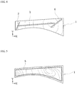
- FIG. 3 is an explanatory view illustrating three rigidity adding shapes arranged by the rigidity improvement method of the aforementioned embodiment on the press-formed product having the initial shape together with the displacement contour of FIG. 2 .
- reference numeral 1 denotes a press-formed product.
- the rigidity improvement method for a press-formed product is to improve the rigidity of the press-formed product 1, which is a front pillar lower inner material as a type of a body part of an automobile, and the press-formed product 1 usually has a trapezoidal shape which is usually easy to bend and twist, i.e., a shape with a low rigidity.
- a press-formed product which is an automobile body part, often has such a low rigidity shape.
- the initial shape of the press-formed product 1 illustrated in FIG. 1 is subjected to a press formation analysis and a springback analysis with a computer using known software, resulting that, as illustrated in FIG.
- the interval of the displacement contours is relatively narrow in a longitudinal direction (X-axis direction) and the displacement contours are asymmetrically distributed in a width direction (Y-axis direction), and falling and twisting occur due to the springback.
- the press-formed product 1 includes three rod-shaped beads 2, 3, 4, which are each a rigidity adding shape, as illustrated in FIG. 3 , and the three rod-shaped beads 2, 3, 4 add rigidity to the initial shape of the press-formed product 1.
- the cross-sectional shape of each of the three rod-shaped beads 2, 3, 4 may be, for example, a smooth sine wave shape for easy formation, may be a rectangular wave shape for further increased rigidity, or may vary between the rod-shaped beads 2, 3, 4.
- the three rod-shaped beads 2, 3, 4 are each arranged so as to extend in a direction of crossing the displacement contours of the initial shape of the press-formed product 1, and adjacent rod-shaped beads 2, 3 and adjacent rod-shaped beads 3, 4 are arranged so as to be overlapped with each other and extended in a direction of crossing the displacement contours, thereby to constitute the press-formed product of the aforementioned embodiment.
- the shape of the press-formed product 1 of the embodiment in which the rod-shaped beads 2, 3, 4 are arranged as described above is subjected to a press formation analysis and a springback analysis with a computer using known software.
- the interval of the displacement contours is relatively wide in the longitudinal direction (X-axis direction), and the displacement contours are symmetrically distributed in the width direction (Y-axis direction), and it can be seen that falling and twisting due to the springback are reduced or eliminated.
- a sheet material forming the press-formed product 1 of the present embodiment can be, for example, a 980 MPa-class high-tensile steel sheet having a thickness t: 0.9 mm, a yield point YP: 620 MPa, a tensile strength TS: 1030 MPa, and an elongation El: 15%.
- the method for producing a press-formed product of an embodiment of the present invention uses a press-forming die of an embodiment of the present invention to press-form the high-tensile steel sheet so as to form the press-formed product 1 of the aforementioned embodiment.
- the press-forming die of the aforementioned embodiment includes, as a die member, a normal punch, die and blank holder.
- the die has a thin trapezoidal shape above outward flanges positioned at upper and lower ends of the press-formed product 1 in FIG. 1 and a concave portion having a shape that corresponds to the rod-shaped beads 2, 3, 4 of FIG. 3 protruding upward from a planar surface of the trapezoidal shape.
- the blank holder holds a steel sheet between the blank holder and a plane surface extending outward from the concave portion of the die.
- the punch pushes the steel sheet, which is held between the die and the blank holder, into the concave of the die to form the steel sheet into a thin trapezoidal shape, and pushes a convex portion of the leading end of the punch into the concave portion of the die so as to form the rod-shaped beads 2, 3, 4 by extrusion on the planar surface of the trapezoidal shape.
- the concave portion of the die and the concave portion of the leading end of the punch of the press-forming die of the aforementioned embodiment are formed such that each of the rod-shaped beads 2, 3, 4 extends in a direction of crossing the displacement contour of the initial shape of the press-formed product 1 and adjacent rod-shaped beads 2, 3 and adjacent rod-shaped beads 3, 4 are overlapped with each other and extended in the direction of crossing the displacement contours.
- the rod-shaped beads 2, 3, 4 arranged thereon extend in the direction of crossing the displacement contour indicating a state of springback in the initial shape of the press-formed product 1, and thus the press-formed product 1 is the press-formed product of the aforementioned embodiment.
- the adjacent rod-shaped beads 2, 3 and the adjacent rod-shaped beads 3, 4 are overlapped with each other and extended in the direction of crossing the displacement contour. Therefore, no gap is formed in the extending direction thereof between the three rod-shaped beads 2, 3, 4 extending in the direction of crossing the displacement contour, and the press-formed product 1 can be prevented from bending along the direction of crossing the displacement contour at the gap portion, so that the springback of the press-formed product 1 can be suppressed effectively.
- FIG. 5 is an explanatory view illustrating a rigidity adding shape arranged by a rigidity improvement method of another embodiment of the present invention on the press-formed product having the initial shape together with the displacement contour of FIG. 2 .
- a frame-shaped bead 5 obtained by connecting rod-shaped beads in a frame shape is arranged as a rigidity adding shape on the initial shape of the press-formed product 1 illustrated in FIG. 1 .
- the frame-shaped bead 5 has a closed profile shape arranged to protrude upward so as to extend along a peripheral edge near the peripheral edge of the trapezoidal shape of the initial shape of the press-formed product 1 illustrated in FIG. 1 .
- the displacement contours usually extend in the direction of crossing the peripheral edge near the peripheral edge of the initial shape. Therefore, by the rigidity improvement method for a press-formed product of the present embodiment, the press-formed product of another embodiment of the present invention whose rigidity is improved by the rigidity improvement method, and the method for producing a press-formed product of another embodiment of the present invention that press-forms the press-formed product, even if the displacement contours are not obtained by a springback analysis, the frame-shaped bead 5 can be arranged so as to extend in the direction of crossing the displacement contour, whereby the springback of the press-formed product 1 can be suppressed easily.
- the press-forming die that produces the press-formed product of the present embodiment whose rigidity is improved by the rigidity improvement method of the present embodiment can also be configured as the press-forming die of the previous embodiment, and the same effect as that obtained by the press-forming die of the previous embodiment can be provided.
- the rigidity improvement method for a press-formed product, the press-forming die, the press-formed product, and the method for producing the press-formed product of the present invention are not limited to the aforementioned embodiments, but can be properly changed within the scope of the claims.
- the shape of the press-formed product or the rigidity adding shape may be a downwardly recessed bead shape, instead of or in addition to the upwardly protruding bead shape, and the frame-shaped bead 5 illustrated in FIG. 5 may have a step shape that is one step higher or lower within the frame instead of the rod-shaped bead shape.
- the rigidity improvement method for a press-formed product, the press-forming die, the press-formed product, and the method for producing the press-formed product of the present invention the springback of the press-formed product having a low rigidity shape can be suppressed effectively.
Landscapes
- Engineering & Computer Science (AREA)
- Mechanical Engineering (AREA)
- Chemical & Material Sciences (AREA)
- Combustion & Propulsion (AREA)
- Transportation (AREA)
- Shaping Metal By Deep-Drawing, Or The Like (AREA)
- Casting Or Compression Moulding Of Plastics Or The Like (AREA)
- Moulds For Moulding Plastics Or The Like (AREA)
Abstract
Description
- The present invention relates to a rigidity improvement method for a press-formed product, a press-forming die, a press-formed product, and a method for producing a press-formed product for suppressing springback at the time when the press-formed product produced by press-forming a sheet material is removed from the press-forming die.
- In recent years, high-strength steel sheets have been more widely used in order to reduce the weight of automobile bodies for improved fuel efficiency. With the use of a high strength steel sheet, the strength, rigidity and the energy absorbed in a collision of an automobile body can be increased without increasing the sheet thickness.
- However, in press-forming which is widely used for processing of body parts of automobiles, failure in shape freezing called springback becomes a problem. The springback occurs when a press-formed product produced by press-forming a steel sheet, which is a sheet material, is removed from a press-forming die and becomes larger when the material strength of the steel sheet increases. The shape defect due to the springback not only impairs the external appearance quality, but also causes failure in welding at the time of assembly of an automobile body. Therefore, the expansion of the use of the high strength steel sheet requires springback measures.
- The springback is caused by elastic recovery generated when a bending moment due to a non-uniform residual stress is released at the removal of a press-formed product from a die. Therefore, there has been proposed a method for mitigating the non-uniform residual stress and a method for reducing the springback by improving the rigidity of the press-formed product as a countermeasure for springback.
- For example,
Patent Literature 1 proposes a method that an emboss is arranged on a stretch flange portion and an excess bead is formed on a shrink flange portion to form an intermediate formed product, and, in the subsequent forming of a final formed product, the emboss is crushed to give the stretch flange portion a compression stress and a tensile stress is applied to the shrink flange portion by the excess bead, such that the residual stress distribution of the press-formed product is made uniform. -
Patent Literature 2 proposes a press-forming method in which, in press-forming a flanged channel-shaped member using a high strength steel sheet, a flange portion is provided with a bead, so that tension applied to a vertical wall portion during press formation is increased to improve the dimension accuracy. -
Patent Literature 3 proposes a technique of preventing generation of warpage by providing a bead at a bottom portion of a square-shaped drawn container along a fillet portion of the long side. -
Patent Literature 4 proposes a technique of suppressing warpage due to a bending moment by providing radial beads on non-pierced portions located between pierced portions that are circumferentially adjacent to each other in a damper plate material that constitutes an automotive clutch or the like. -
- Patent Literature 1:
JP-B-5380890 - Patent Literature 2:
JP-A-H11-290951 - Patent Literature 3:
JP-A-2008-105088 - Patent Literature 4:
JP-A-2017-154160 -
Patent Literature 1 proposes a method in which an emboss is formed on a stretch flange portion and an excess bead is formed on a shrink flange portion to make a residual stress uniform for reduction of the springback. However, in a press-formed product having a low-rigidity shape to which the present invention is mainly directed, the springback is generated even by a low stress, and therefore, even a reduction in stress of a specific portion may be insufficient. In addition, in a state where a new stress is generated as a result of the reduction in stress of a specific portion, springback in another form can occur. Therefore, with a press-formed product having a low-rigidity shape, it is difficult to efficiently take a countermeasure for springback through stress control. -
Patent Literature 2 proposes a press-forming method in which, in press-forming a flanged channel-shaped member using a high strength steel sheet, a flange portion is provided with a bead so that tension applied to a vertical wall portion during press-forming is increased to improve the dimension accuracy. In addition,Patent Literature 3 proposes a technique of preventing generation of warpage by providing a bead at a bottom portion of a square-shaped drawn container along a fillet portion of the long side. These techniques are effective when it is preliminarily known technically or empirically as to on which portion the bead should be set. However, a press-formed product having a low rigidity shape to which the present invention is mainly directed originally has a low rigidity, and the springback can be generated even by a low stress. Thus, the starting position or direction of the springback can easily change. Therefore, the position or direction of the bead, the number of beads to be set, and the like optimal for suppressing the springback are not necessarily constant. -
Patent Literature 4 proposes a technique of suppressing warpage due to a bending moment by providing beads on non-pierced portions located between pierced portions that are circumferentially adjacent to each other in a damper plate material, in which it is desirable to provide the beads in a direction of crossing, particularly a direction perpendicular to a straight line connecting a pair of mutually adjacent pierced portions. However, a press-formed product does not necessarily have a symmetrical shape, and therefore the bead setting location is not always determined uniquely depending on the shape of a part. - Specifically, the problems of the conventional techniques to be solved are listed below.
- (1) To set a part with low rigidity to have a press-formed product shape effective for suppressing the springback.
- (2) To determine an optimal arrangement of a rigidity adding shape effective for reducing the springback of a press-formed product having a low rigidity shape.
- The present invention has been made in view of the aforementioned problems inherent to the conventional techniques, and it is an object of the present invention to provide a rigidity improvement method that is effective for springback suppression measures by improving a rigidity of a press-formed product with a low rigidity shape, and can press-form a press-formed product having a small amount of springback after press-forming and an excellent shape fixability, a press-forming die using the method, a press-formed product, and a method for producing the press-formed product.
- A rigidity improvement method for a press-formed product of the present invention is characterized in that
in improving rigidity of a press-formed product produced by press-forming a sheet material by a rigidity adding shape to suppress springback at a time when the press-formed product is removed from a die,
the rigidity adding shape is arranged so as to extend in a direction of crossing a displacement contour indicating a state of springback in an initial shape prior to the arrangement of the rigidity adding shape of the press-formed product. - Further, a press-forming die of the present invention using the aforementioned rigidity improvement method is a press-forming die for producing a press-formed product on which a rigidity adding shape is arranged, from a sheet material to suppress springback at a time when the press-formed product is removed from a die, comprising:
a die member configured to form the rigidity adding shape so as to extend in a direction of crossing a displacement contour indicating a state of springback in an initial shape prior to the arrangement of the rigidity adding shape of the press-formed product. - Further, a press-formed product of the present invention using the aforementioned rigidity improvement method is a press-formed product produced by press-forming a sheet material and on which a rigidity adding shape is arranged, to suppress springback at a time of removal from a die, in which
the rigidity adding shape is arranged so as to extend in a direction of crossing a displacement contour indicating a state of springback in an initial shape prior to the arrangement of the rigidity adding shape of the press-formed product. - Further, a method for producing a press-formed product of the present invention is characterized in that
in producing a press-formed product on which a rigidity adding shape is arranged by press-forming a sheet material to suppress springback at a time of removal from a die,
the rigidity adding shape is arranged so as to extend in a direction of crossing a displacement contour indicating a state of springback in an initial shape prior to the arrangement of the rigidity adding shape of the press-formed product. - In the rigidity improvement method for a press-formed product of the present invention, in improving the rigidity of a press-formed product produced by press-forming a sheet material by a rigidity adding shape to suppress the springback at the time when the press-formed product is removed from a die, the rigidity adding shape is arranged so as to extend in a direction of crossing a displacement contour indicating a state of springback in an initial shape prior to the arrangement of the rigidity adding shape of the press-formed product. Therefore, falling or rising of an end of the press-formed product or twisting of the press-formed product that occurs when the press-formed product is bent along the direction of crossing the displacement contour at a removal from the die can be effectively suppressed by the rigidity adding shape, and the springback of the press-formed product having a low rigidity shape can be effectively suppressed.
- In addition, with the press-forming die of the present invention, the die member of the press-forming die forms the rigidity adding shape on the press-formed product so as to extend in a direction of crossing the displacement contour indicating a state of springback in an initial shape prior to the arrangement of the rigidity adding shape of the press-formed product. Therefore, falling or rising of an end of the press-formed product or twisting of the press-formed product that occurs when the press-formed product is bent along the direction of crossing the displacement contour at a removal from the die can be effectively suppressed by the rigidity adding shape, and the springback of the press-formed product having a low rigidity shape can be effectively suppressed.
- Further, with the press-formed product and by the method for producing the press-formed product of the present invention, in order to suppress springback at the time of removal from the die, the press-formed product is produced by press-forming a sheet material and the rigidity adding shape is arranged thereon so as to extend in the direction of crossing the displacement contour indicating a state of springback in an initial shape prior to the arrangement of the rigidity adding shape of the press-formed product. Therefore, falling or rising of an end of the press-formed product or twisting of the press-formed product that occurs when the press-formed product is bent along the direction of crossing the displacement contour at a removal from the die can be effectively suppressed by the rigidity adding shape, and the springback of the press-formed product having a low rigidity shape can be effectively suppressed.
- Note that, by the rigidity improvement method for a press-formed product, the press-forming die, the press-formed product, and the method for producing the press-formed product of the present invention, the displacement contour may be obtained by a springback analysis of the initial shape, and the rigidity adding shape may be arranged so as to extend in the direction of crossing the displacement contour. Thus, the rigidity adding shape can be appropriately arranged at a position inside the initial shape where the direction of crossing the displacement contour is unclear.
- In the aforementioned case, a plurality of rigidity adding shapes may be arranged so as to extend in the direction of crossing the displacement contour, and adjacent rigidity adding shapes of the plurality of rigidity adding shapes may be overlapped with each other and extended in the direction of crossing the displacement contour. Thus, no gap is formed in the extending direction thereof between the plurality of rigidity adding shapes extending in the direction of crossing the displacement contour, and the press-formed product can be prevented from bending along the direction of crossing the displacement contour at the gap portion, so that the springback of the press-formed product can be suppressed effectively.
- In addition, by the rigidity improvement method for a press-formed product, the press-forming die, the press-formed product, and the method for producing the press-formed product of the present invention, the rigidity adding shape may have a closed profile shape arranged so as to extend along a peripheral edge of the initial shape. Thus, since the displacement contour usually extends in the direction of crossing the peripheral edge of the initial shape, even if the displacement contour is not obtained by a springback analysis, the rigidity adding shape can be arranged so as to extend in the direction of crossing the displacement contour, and therefore the springback of the press-formed product can be suppressed easily.
-
-
FIG. 1 is a perspective view illustrating an initial shape of a press-formed product according to an embodiment of the present invention whose rigidity is to be improved by a rigidity improvement method for a press-formed product according to an embodiment of the present invention. -
FIG. 2 is a plan view illustrating a height directional displacement distribution by a springback analysis of the press-formed product having the initial shape by displacement contour. -
FIG. 3 is an explanatory view illustrating three rigidity adding shapes arranged by the rigidity improvement method of the aforementioned embodiment on the press-formed product having the initial shape together with the displacement contour ofFIG. 2 . -
FIG. 4 is a plan view illustrating a height directional displacement distribution by a springback analysis of a press-formed product of an embodiment of the present invention on which the three rigidity adding shapes are arranged by displacement contour. -
FIG. 5 is an explanatory view illustrating a rigidity adding shape arranged by the rigidity improvement method of another embodiment of the present invention on the press-formed product having the initial shape together with the displacement contour ofFIG. 2 . - Embodiments of the present invention will be described in detail below on the basis of the drawings. Here,
FIG. 1 is a perspective view illustrating an initial shape of a press-formed product according to an embodiment of the present invention whose rigidity is to be improved by a rigidity improvement method for a press-formed product according to an embodiment of the present invention.FIG. 2 is a plan view illustrating a height directional displacement distribution by a springback analysis of the press-formed product having the initial shape by displacement contour.FIG. 3 is an explanatory view illustrating three rigidity adding shapes arranged by the rigidity improvement method of the aforementioned embodiment on the press-formed product having the initial shape together with the displacement contour ofFIG. 2 . In the drawings,reference numeral 1 denotes a press-formed product. - The rigidity improvement method for a press-formed product according to the aforementioned embodiment is to improve the rigidity of the press-formed
product 1, which is a front pillar lower inner material as a type of a body part of an automobile, and the press-formedproduct 1 usually has a trapezoidal shape which is usually easy to bend and twist, i.e., a shape with a low rigidity. Note that a press-formed product, which is an automobile body part, often has such a low rigidity shape. The initial shape of the press-formedproduct 1 illustrated inFIG. 1 is subjected to a press formation analysis and a springback analysis with a computer using known software, resulting that, as illustrated inFIG. 2 , it can be seen that the interval of the displacement contours is relatively narrow in a longitudinal direction (X-axis direction) and the displacement contours are asymmetrically distributed in a width direction (Y-axis direction), and falling and twisting occur due to the springback. - Thus, in the rigidity improvement method for a press-formed product of the present embodiment, the press-formed
product 1 includes three rod-shapedbeads FIG. 3 , and the three rod-shapedbeads product 1. Note that the cross-sectional shape of each of the three rod-shapedbeads beads - In the rigidity improvement method for a press-formed product of the present embodiment, the three rod-shaped
beads product 1, and adjacent rod-shapedbeads beads - As is the case for the initial shape, the shape of the press-formed
product 1 of the embodiment in which the rod-shapedbeads FIG. 4 , the interval of the displacement contours is relatively wide in the longitudinal direction (X-axis direction), and the displacement contours are symmetrically distributed in the width direction (Y-axis direction), and it can be seen that falling and twisting due to the springback are reduced or eliminated. - A sheet material forming the press-formed
product 1 of the present embodiment can be, for example, a 980 MPa-class high-tensile steel sheet having a thickness t: 0.9 mm, a yield point YP: 620 MPa, a tensile strength TS: 1030 MPa, and an elongation El: 15%. The method for producing a press-formed product of an embodiment of the present invention uses a press-forming die of an embodiment of the present invention to press-form the high-tensile steel sheet so as to form the press-formedproduct 1 of the aforementioned embodiment. - Therefore, the press-forming die of the aforementioned embodiment includes, as a die member, a normal punch, die and blank holder. The die has a thin trapezoidal shape above outward flanges positioned at upper and lower ends of the press-formed
product 1 inFIG. 1 and a concave portion having a shape that corresponds to the rod-shapedbeads FIG. 3 protruding upward from a planar surface of the trapezoidal shape. The blank holder holds a steel sheet between the blank holder and a plane surface extending outward from the concave portion of the die. The punch pushes the steel sheet, which is held between the die and the blank holder, into the concave of the die to form the steel sheet into a thin trapezoidal shape, and pushes a convex portion of the leading end of the punch into the concave portion of the die so as to form the rod-shapedbeads - Here, the concave portion of the die and the concave portion of the leading end of the punch of the press-forming die of the aforementioned embodiment are formed such that each of the rod-shaped
beads product 1 and adjacent rod-shapedbeads beads - By the method for producing the press-formed product of the aforementioned embodiment, on the press-formed
product 1 formed using the press-forming die of the aforementioned embodiment, the rod-shapedbeads product 1, and thus the press-formedproduct 1 is the press-formed product of the aforementioned embodiment. With the press-formed product of the present embodiment and by the method for producing the press-formed product, falling or rising of an end of the press-formedproduct 1 or twisting of the press-formedproduct 1 that occurs when the press-formedproduct 1 is bent along the direction of crossing the displacement contour at a removal from the die can be effectively suppressed by the rod-shapedbeads product 1 can be effectively suppressed. - Moreover, with the press-formed product of the present embodiment and by the method for producing the press-formed product, the adjacent rod-shaped
beads beads beads product 1 can be prevented from bending along the direction of crossing the displacement contour at the gap portion, so that the springback of the press-formedproduct 1 can be suppressed effectively. -
FIG. 5 is an explanatory view illustrating a rigidity adding shape arranged by a rigidity improvement method of another embodiment of the present invention on the press-formed product having the initial shape together with the displacement contour ofFIG. 2 . In the rigidity improvement method for a press-formed product of the present embodiment, a frame-shapedbead 5 obtained by connecting rod-shaped beads in a frame shape is arranged as a rigidity adding shape on the initial shape of the press-formedproduct 1 illustrated inFIG. 1 . The frame-shapedbead 5 has a closed profile shape arranged to protrude upward so as to extend along a peripheral edge near the peripheral edge of the trapezoidal shape of the initial shape of the press-formedproduct 1 illustrated inFIG. 1 . - The displacement contours usually extend in the direction of crossing the peripheral edge near the peripheral edge of the initial shape. Therefore, by the rigidity improvement method for a press-formed product of the present embodiment, the press-formed product of another embodiment of the present invention whose rigidity is improved by the rigidity improvement method, and the method for producing a press-formed product of another embodiment of the present invention that press-forms the press-formed product, even if the displacement contours are not obtained by a springback analysis, the frame-shaped
bead 5 can be arranged so as to extend in the direction of crossing the displacement contour, whereby the springback of the press-formedproduct 1 can be suppressed easily. - Further, the press-forming die that produces the press-formed product of the present embodiment whose rigidity is improved by the rigidity improvement method of the present embodiment can also be configured as the press-forming die of the previous embodiment, and the same effect as that obtained by the press-forming die of the previous embodiment can be provided.
- The embodiments have been described heretofore. However, the rigidity improvement method for a press-formed product, the press-forming die, the press-formed product, and the method for producing the press-formed product of the present invention are not limited to the aforementioned embodiments, but can be properly changed within the scope of the claims. For example, the shape of the press-formed product or the rigidity adding shape may be a downwardly recessed bead shape, instead of or in addition to the upwardly protruding bead shape, and the frame-shaped
bead 5 illustrated inFIG. 5 may have a step shape that is one step higher or lower within the frame instead of the rod-shaped bead shape. - Thus, by the rigidity improvement method for a press-formed product, the press-forming die, the press-formed product, and the method for producing the press-formed product of the present invention, the springback of the press-formed product having a low rigidity shape can be suppressed effectively.
-
- 1
- press-formed product
- 2, 3, 4
- rod-shaped bead (rigidity adding shape)
- 5
- frame-shaped bead (rigidity adding shape)
Claims (16)
- A rigidity improvement method for a press-formed product,
characterized in that
in improving rigidity of a press-formed product produced by press-forming a sheet material by a rigidity adding shape, to suppress springback at a time when the press-formed product is removed from a die,
the rigidity adding shape is arranged so as to extend in a direction of crossing a displacement contour indicating a state of springback in an initial shape prior to an arrangement of the rigidity adding shape of the press-formed product. - The rigidity improvement method for a press-formed product according to claim 1, wherein
the displacement contour is obtained by a springback analysis of the initial shape, and the rigidity adding shape is arranged so as to extend in the direction of crossing the displacement contour. - The rigidity improvement method for a press-formed product according to claim 2, wherein
a plurality of rigidity adding shapes are arranged so as to extend in the direction of crossing the displacement contour, and
adjacent rigidity adding shapes of the plurality of rigidity adding shapes are overlapped with each other and extended in the direction of crossing the displacement contour. - The rigidity improvement method for a press-formed product according to claim 1, wherein
the rigidity adding shape has a closed profile shape arranged so as to extend along a peripheral edge of the initial shape. - A press-forming die for producing a press-formed product on which a rigidity adding shape is arranged from a sheet material to suppress springback at a time when the press-formed product is removed from a die,
characterized in that
the press-forming die comprises a die member configured to form the rigidity adding shape so as to extend in a direction of crossing a displacement contour indicating a state of springback in an initial shape prior to an arrangement of the rigidity adding shape of the press-formed product. - The press-forming die according to claim 5, wherein
the displacement contour is obtained by a springback analysis of the initial shape, and the rigidity adding shape is arranged so as to extend in the direction of crossing the displacement contour. - The press-forming die according to claim 6, wherein
a plurality of rigidity adding shapes are arranged so as to extend in the direction of crossing the displacement contour, and
adjacent rigidity adding shapes of the plurality of rigidity adding shapes are overlapped with each other and extended in the direction of crossing the displacement contour. - The press-forming die according to claim 5, wherein
the rigidity adding shape has a closed profile shape arranged so as to extend along a peripheral edge of the initial shape. - A press-formed product produced by press-forming a sheet material and on which a rigidity adding shape is arranged to suppress springback at a time when the press-formed product is removed from a die,
characterized in that
the rigidity adding shape is arranged so as to extend in a direction of crossing a displacement contour indicating a state of springback in an initial shape prior to an arrangement of the rigidity adding shape of the press-formed product. - The press-formed product according to claim 9, wherein
the displacement contour is obtained by a springback analysis of the initial shape, and the rigidity adding shape is arranged so as to extend in a direction of crossing the displacement contour. - The press-formed product according to claim 10, wherein
a plurality of rigidity adding shapes are arranged so as to extend in the direction of crossing the displacement contour, and
adjacent rigidity adding shapes of the plurality of rigidity adding shapes are overlapped with each other and extended in the direction of crossing the displacement contour. - The press-formed product according to claim 9, wherein
the rigidity adding shape has a closed profile shape arranged so as to extend along a peripheral edge of the initial shape. - A method for producing a press-formed product,
characterized in that
in producing a press-formed product on which a rigidity adding shape is arranged by press-forming a sheet material, to suppress springback at a time of removal from a die,
the rigidity adding shape is arranged so as to extend in a direction of crossing a displacement contour indicating a state of springback in an initial shape prior to an arrangement of the rigidity adding shape of the press-formed product. - The method for producing a press-formed product according to claim 13, wherein
the displacement contour is obtained by a springback analysis of the initial shape, and
the rigidity adding shape is arranged so as to extend in a direction of crossing the displacement contour. - The method for producing a press-formed product according to claim 14, wherein
a plurality of rigidity adding shapes are arranged so as to extend in the direction of crossing the displacement contour, and
adjacent rigidity adding shapes of the plurality of rigidity adding shapes are overlapped with each other and extended in the direction of crossing the displacement contour. - The method for producing a press-formed product according to claim 13, wherein
the rigidity adding shape has a closed profile shape arranged so as to extend along a peripheral edge of the initial shape.
Applications Claiming Priority (2)
| Application Number | Priority Date | Filing Date | Title |
|---|---|---|---|
| JP2018062817 | 2018-03-28 | ||
| PCT/JP2019/006935 WO2019187864A1 (en) | 2018-03-28 | 2019-02-25 | Rigidity improvement method for press-molded article, press-molding die, press-molded article, and production method for press-molded article |
Publications (2)
| Publication Number | Publication Date |
|---|---|
| EP3778057A1 true EP3778057A1 (en) | 2021-02-17 |
| EP3778057A4 EP3778057A4 (en) | 2021-05-19 |
Family
ID=68061266
Family Applications (1)
| Application Number | Title | Priority Date | Filing Date |
|---|---|---|---|
| EP19775909.5A Pending EP3778057A4 (en) | 2018-03-28 | 2019-02-25 | Rigidity improvement method for press-molded article, press-molding die, press-molded article, and production method for press-molded article |
Country Status (7)
| Country | Link |
|---|---|
| US (1) | US20210237137A1 (en) |
| EP (1) | EP3778057A4 (en) |
| JP (1) | JP6959993B2 (en) |
| KR (1) | KR102364201B1 (en) |
| CN (1) | CN111757784B (en) |
| MX (1) | MX2020010072A (en) |
| WO (1) | WO2019187864A1 (en) |
Families Citing this family (1)
| Publication number | Priority date | Publication date | Assignee | Title |
|---|---|---|---|---|
| JP7664103B2 (en) | 2021-07-05 | 2025-04-17 | 株式会社日立製作所 | Railway vehicle body structure |
Family Cites Families (17)
| Publication number | Priority date | Publication date | Assignee | Title |
|---|---|---|---|---|
| JPH11290951A (en) | 1998-04-07 | 1999-10-26 | Nippon Steel Corp | Press forming method and press forming apparatus for high strength steel sheet |
| JP2003127898A (en) * | 2001-10-23 | 2003-05-08 | Toyota Motor Corp | Front pillar structure |
| JP2006240586A (en) * | 2005-03-07 | 2006-09-14 | Mazda Motor Corp | Car body floor panel structure |
| JP2007125951A (en) * | 2005-11-02 | 2007-05-24 | Mitsubishi Motors Corp | Front pillar lower structure |
| CN103995927B (en) * | 2006-08-31 | 2017-01-04 | 新日铁住金株式会社 | Resilience countermeasure position specifying method and resilience countermeasure position specific device |
| JP5122789B2 (en) | 2006-10-27 | 2013-01-16 | 東洋製罐株式会社 | Square drawn container and method for forming the same |
| JP2008213028A (en) * | 2007-02-28 | 2008-09-18 | Press Kogyo Co Ltd | Twist preventing method for channel |
| CN201164888Y (en) * | 2008-03-21 | 2008-12-17 | 众泰控股集团有限公司 | Automobile overall side wall drawing die |
| JP5380890B2 (en) | 2008-04-15 | 2014-01-08 | 新日鐵住金株式会社 | Press molding method and apparatus excellent in shape freezing property |
| TWI438041B (en) * | 2008-09-30 | 2014-05-21 | Nippon Steel & Sumitomo Metal Corp | Forming simulation method, forming simulation apparatus, forming simuration program and media for storing the program, and forming method using the simulation result |
| JP5360156B2 (en) * | 2011-08-01 | 2013-12-04 | トヨタ自動車株式会社 | Vehicle back door structure |
| US10262086B2 (en) * | 2012-03-30 | 2019-04-16 | Nippon Steel & Sumitomo Metal Corporation | Analyzing apparatus, analyzing method, and computer program |
| US10161892B2 (en) * | 2013-02-08 | 2018-12-25 | Jfe Steel Corporation | Method of analyzing press forming |
| JP5861749B1 (en) * | 2014-07-30 | 2016-02-16 | Jfeスチール株式会社 | Press forming method |
| JP6235542B2 (en) * | 2015-09-15 | 2017-11-22 | 本田技研工業株式会社 | Body front structure |
| JP2017154160A (en) | 2016-03-02 | 2017-09-07 | トヨタ自動車株式会社 | Hole punching method |
| JP6794823B2 (en) * | 2016-12-27 | 2020-12-02 | 日本製鉄株式会社 | Analytical equipment, analysis methods, and computer programs |
-
2019
- 2019-02-25 EP EP19775909.5A patent/EP3778057A4/en active Pending
- 2019-02-25 KR KR1020207026795A patent/KR102364201B1/en active Active
- 2019-02-25 WO PCT/JP2019/006935 patent/WO2019187864A1/en not_active Ceased
- 2019-02-25 CN CN201980015038.7A patent/CN111757784B/en active Active
- 2019-02-25 JP JP2019562027A patent/JP6959993B2/en active Active
- 2019-02-25 US US17/042,069 patent/US20210237137A1/en not_active Abandoned
- 2019-02-25 MX MX2020010072A patent/MX2020010072A/en unknown
Also Published As
| Publication number | Publication date |
|---|---|
| MX2020010072A (en) | 2020-10-28 |
| WO2019187864A1 (en) | 2019-10-03 |
| KR20200119331A (en) | 2020-10-19 |
| JPWO2019187864A1 (en) | 2020-04-30 |
| CN111757784A (en) | 2020-10-09 |
| US20210237137A1 (en) | 2021-08-05 |
| CN111757784B (en) | 2022-06-17 |
| KR102364201B1 (en) | 2022-02-16 |
| EP3778057A4 (en) | 2021-05-19 |
| JP6959993B2 (en) | 2021-11-05 |
Similar Documents
| Publication | Publication Date | Title |
|---|---|---|
| KR101663433B1 (en) | Press-forming mold and method for manufacturing press-formed product | |
| CN111727089B (en) | Method for manufacturing press-molded member, press-molding device, and metal plate for press-molding | |
| KR102007557B1 (en) | Method for manufacturing press-molded article, and press-molded article | |
| CN104903020A (en) | Method for producing press-molded article | |
| CN115210013B (en) | Manufacturing methods for stamped parts, metal sheets for stamping, and high-tensile steel sheets | |
| US12151274B2 (en) | Press forming method | |
| US10500624B2 (en) | Press forming method and tool of press forming | |
| JP6672933B2 (en) | Automotive structural member, manufacturing method thereof, and mold | |
| CN113286672B (en) | Press molding method, blanking of plate-like material, intermediate molded article, method for producing press molded article, and press molded article | |
| CN107921504A (en) | The manufacture method of stretch flange formation of parts | |
| EP4137245B1 (en) | Press-forming mold and press-forming method | |
| EP3778053A1 (en) | Designing method for press-molded article, press-molding die, press-molded article, and production method for press-molded article | |
| CN105848801A (en) | Stamping method and method of manufacturing a stamped part | |
| JP2024035883A (en) | Manufacturing method of press molded products | |
| US20210237137A1 (en) | Rigidity improvement method for press-formed product, press-forming die, press-formed product, and method of producing press-formed product | |
| JP6665612B2 (en) | Method for manufacturing press-formed product and press device | |
| JP5079604B2 (en) | Metal mold for press forming of cross-section hat-shaped member and press molding method | |
| JP2017042825A (en) | Manufacturing method for molded component with stretch flange | |
| JP7070287B2 (en) | Manufacturing method of press-molded parts and press-molded parts | |
| JP2019098376A (en) | Method for manufacturing press molding | |
| JP2020163416A (en) | The press forming method, the press forming die used in the method, and the body parts press formed by the press forming die. | |
| KR20250076609A (en) | Method for manufacturing press-molded products | |
| WO2024042593A1 (en) | Manufacturing method and blank for press-formed product | |
| KR20230003551A (en) | Press forming method |
Legal Events
| Date | Code | Title | Description |
|---|---|---|---|
| STAA | Information on the status of an ep patent application or granted ep patent |
Free format text: STATUS: THE INTERNATIONAL PUBLICATION HAS BEEN MADE |
|
| PUAI | Public reference made under article 153(3) epc to a published international application that has entered the european phase |
Free format text: ORIGINAL CODE: 0009012 |
|
| STAA | Information on the status of an ep patent application or granted ep patent |
Free format text: STATUS: REQUEST FOR EXAMINATION WAS MADE |
|
| 17P | Request for examination filed |
Effective date: 20201002 |
|
| AK | Designated contracting states |
Kind code of ref document: A1 Designated state(s): AL AT BE BG CH CY CZ DE DK EE ES FI FR GB GR HR HU IE IS IT LI LT LU LV MC MK MT NL NO PL PT RO RS SE SI SK SM TR |
|
| AX | Request for extension of the european patent |
Extension state: BA ME |
|
| A4 | Supplementary search report drawn up and despatched |
Effective date: 20210415 |
|
| RIC1 | Information provided on ipc code assigned before grant |
Ipc: B21D 22/20 20060101AFI20210409BHEP Ipc: B21D 22/00 20060101ALI20210409BHEP Ipc: B21D 22/26 20060101ALI20210409BHEP Ipc: B21D 24/00 20060101ALI20210409BHEP Ipc: B21D 22/22 20060101ALI20210409BHEP Ipc: B21D 17/02 20060101ALI20210409BHEP Ipc: B21D 22/02 20060101ALI20210409BHEP Ipc: B21D 22/04 20060101ALI20210409BHEP Ipc: B21D 53/88 20060101ALN20210409BHEP |
|
| DAV | Request for validation of the european patent (deleted) | ||
| DAX | Request for extension of the european patent (deleted) | ||
| STAA | Information on the status of an ep patent application or granted ep patent |
Free format text: STATUS: EXAMINATION IS IN PROGRESS |
|
| 17Q | First examination report despatched |
Effective date: 20230202 |