EP3778033A1 - Dust collection electrode assembly, air purification device and control method therefor - Google Patents
Dust collection electrode assembly, air purification device and control method therefor Download PDFInfo
- Publication number
- EP3778033A1 EP3778033A1 EP18921673.2A EP18921673A EP3778033A1 EP 3778033 A1 EP3778033 A1 EP 3778033A1 EP 18921673 A EP18921673 A EP 18921673A EP 3778033 A1 EP3778033 A1 EP 3778033A1
- Authority
- EP
- European Patent Office
- Prior art keywords
- dust collection
- collection electrode
- electrode assembly
- side edge
- purification device
- Prior art date
- Legal status (The legal status is an assumption and is not a legal conclusion. Google has not performed a legal analysis and makes no representation as to the accuracy of the status listed.)
- Pending
Links
Images


Classifications
-
- B—PERFORMING OPERATIONS; TRANSPORTING
- B03—SEPARATION OF SOLID MATERIALS USING LIQUIDS OR USING PNEUMATIC TABLES OR JIGS; MAGNETIC OR ELECTROSTATIC SEPARATION OF SOLID MATERIALS FROM SOLID MATERIALS OR FLUIDS; SEPARATION BY HIGH-VOLTAGE ELECTRIC FIELDS
- B03C—MAGNETIC OR ELECTROSTATIC SEPARATION OF SOLID MATERIALS FROM SOLID MATERIALS OR FLUIDS; SEPARATION BY HIGH-VOLTAGE ELECTRIC FIELDS
- B03C3/00—Separating dispersed particles from gases or vapour, e.g. air, by electrostatic effect
- B03C3/34—Constructional details or accessories or operation thereof
- B03C3/40—Electrode constructions
- B03C3/45—Collecting-electrodes
- B03C3/47—Collecting-electrodes flat, e.g. plates, discs, gratings
-
- B—PERFORMING OPERATIONS; TRANSPORTING
- B03—SEPARATION OF SOLID MATERIALS USING LIQUIDS OR USING PNEUMATIC TABLES OR JIGS; MAGNETIC OR ELECTROSTATIC SEPARATION OF SOLID MATERIALS FROM SOLID MATERIALS OR FLUIDS; SEPARATION BY HIGH-VOLTAGE ELECTRIC FIELDS
- B03C—MAGNETIC OR ELECTROSTATIC SEPARATION OF SOLID MATERIALS FROM SOLID MATERIALS OR FLUIDS; SEPARATION BY HIGH-VOLTAGE ELECTRIC FIELDS
- B03C3/00—Separating dispersed particles from gases or vapour, e.g. air, by electrostatic effect
- B03C3/01—Pretreatment of the gases prior to electrostatic precipitation
- B03C3/011—Prefiltering; Flow controlling
-
- B—PERFORMING OPERATIONS; TRANSPORTING
- B03—SEPARATION OF SOLID MATERIALS USING LIQUIDS OR USING PNEUMATIC TABLES OR JIGS; MAGNETIC OR ELECTROSTATIC SEPARATION OF SOLID MATERIALS FROM SOLID MATERIALS OR FLUIDS; SEPARATION BY HIGH-VOLTAGE ELECTRIC FIELDS
- B03C—MAGNETIC OR ELECTROSTATIC SEPARATION OF SOLID MATERIALS FROM SOLID MATERIALS OR FLUIDS; SEPARATION BY HIGH-VOLTAGE ELECTRIC FIELDS
- B03C3/00—Separating dispersed particles from gases or vapour, e.g. air, by electrostatic effect
- B03C3/019—Post-treatment of gases
-
- B—PERFORMING OPERATIONS; TRANSPORTING
- B03—SEPARATION OF SOLID MATERIALS USING LIQUIDS OR USING PNEUMATIC TABLES OR JIGS; MAGNETIC OR ELECTROSTATIC SEPARATION OF SOLID MATERIALS FROM SOLID MATERIALS OR FLUIDS; SEPARATION BY HIGH-VOLTAGE ELECTRIC FIELDS
- B03C—MAGNETIC OR ELECTROSTATIC SEPARATION OF SOLID MATERIALS FROM SOLID MATERIALS OR FLUIDS; SEPARATION BY HIGH-VOLTAGE ELECTRIC FIELDS
- B03C3/00—Separating dispersed particles from gases or vapour, e.g. air, by electrostatic effect
- B03C3/02—Plant or installations having external electricity supply
- B03C3/04—Plant or installations having external electricity supply dry type
- B03C3/08—Plant or installations having external electricity supply dry type characterised by presence of stationary flat electrodes arranged with their flat surfaces parallel to the gas stream
-
- B—PERFORMING OPERATIONS; TRANSPORTING
- B03—SEPARATION OF SOLID MATERIALS USING LIQUIDS OR USING PNEUMATIC TABLES OR JIGS; MAGNETIC OR ELECTROSTATIC SEPARATION OF SOLID MATERIALS FROM SOLID MATERIALS OR FLUIDS; SEPARATION BY HIGH-VOLTAGE ELECTRIC FIELDS
- B03C—MAGNETIC OR ELECTROSTATIC SEPARATION OF SOLID MATERIALS FROM SOLID MATERIALS OR FLUIDS; SEPARATION BY HIGH-VOLTAGE ELECTRIC FIELDS
- B03C3/00—Separating dispersed particles from gases or vapour, e.g. air, by electrostatic effect
- B03C3/02—Plant or installations having external electricity supply
- B03C3/04—Plant or installations having external electricity supply dry type
- B03C3/10—Plant or installations having external electricity supply dry type characterised by presence of electrodes moving during separating action
-
- B—PERFORMING OPERATIONS; TRANSPORTING
- B03—SEPARATION OF SOLID MATERIALS USING LIQUIDS OR USING PNEUMATIC TABLES OR JIGS; MAGNETIC OR ELECTROSTATIC SEPARATION OF SOLID MATERIALS FROM SOLID MATERIALS OR FLUIDS; SEPARATION BY HIGH-VOLTAGE ELECTRIC FIELDS
- B03C—MAGNETIC OR ELECTROSTATIC SEPARATION OF SOLID MATERIALS FROM SOLID MATERIALS OR FLUIDS; SEPARATION BY HIGH-VOLTAGE ELECTRIC FIELDS
- B03C3/00—Separating dispersed particles from gases or vapour, e.g. air, by electrostatic effect
- B03C3/02—Plant or installations having external electricity supply
- B03C3/04—Plant or installations having external electricity supply dry type
- B03C3/12—Plant or installations having external electricity supply dry type characterised by separation of ionising and collecting stations
-
- B—PERFORMING OPERATIONS; TRANSPORTING
- B03—SEPARATION OF SOLID MATERIALS USING LIQUIDS OR USING PNEUMATIC TABLES OR JIGS; MAGNETIC OR ELECTROSTATIC SEPARATION OF SOLID MATERIALS FROM SOLID MATERIALS OR FLUIDS; SEPARATION BY HIGH-VOLTAGE ELECTRIC FIELDS
- B03C—MAGNETIC OR ELECTROSTATIC SEPARATION OF SOLID MATERIALS FROM SOLID MATERIALS OR FLUIDS; SEPARATION BY HIGH-VOLTAGE ELECTRIC FIELDS
- B03C3/00—Separating dispersed particles from gases or vapour, e.g. air, by electrostatic effect
- B03C3/34—Constructional details or accessories or operation thereof
- B03C3/86—Electrode-carrying means
Definitions
- the present invention relates to the field of air purification technology, and particularly to a dust collection electrode assembly, an air purification device and a control method thereof.
- the air purifier is usually divided into a filter type air purifier and an electrostatic type air purifier.
- the filter type air purifier uses a filter screen to filter particulate impurities such as PM2.5 and the like in the air.
- the filter screen in this type of air purifier needs to be regularly replaced, which increases the usage cost.
- the electrostatic type air purifier purifies the air in an electric purification mode, and there is no need to replace its consumables as long as its internal electrode plates are cleaned regularly, thereby saving the usage cost.
- the dust collection capability of the electrode plate is easily weakened due to dust accumulation. Therefore, a user needs to frequently clean the electrode plate to ensure the purification effect of the purifier, which affects the user experience.
- a dust collection electrode assembly applied to an air purification device is provided, the air purification device further includes a generation electrode assembly, the dust collection electrode assembly includes a dust collection electrode, the dust collection electrode is moveable to change at least one of a position state and an orientation state of the dust collection electrode relative to the generation electrode assembly.
- the dust collection electrode assembly further includes a dust collection electrode support structure, the dust collection electrode is moveable relative to the dust collection electrode support structure.
- the dust collection electrode assembly applied to an air purification device further includes a generation electrode assembly, the dust collection electrode assembly includes a dust collection electrode and a dust collection electrode support structure, the dust collection electrode is moveable relative to the dust collection electrode support structure to change at least one of a position state and an orientation state of the dust collection electrode relative to the generation electrode assembly.
- the dust collection electrode includes an electrode plate body and a plurality of dust collection structures provided on the electrode plate body, when the dust collection electrode is in different position states and/or orientation states relative to the generation electrode assembly, the generation electrode assembly is arranged opposite to different dust collection structures.
- the plurality of dust collection structures are respectively provided on a first side edge and a second side edge of the electrode plate body, the first side edge is opposite to the second side edge.
- a dust collection structure includes a protrusion provided on a side edge of the electrode plate body.
- the protrusion extends in a direction same as an extension direction of the side edge, and a cross section of the protrusion is a portion of a circle.
- the dust collection electrode support structure includes a frame structure, the dust collection electrode is provided in the frame structure and is turnable around an axis parallel to the first side edge, such that the dust collection electrode turnable between a first position and a second position; in the first position, a dust collection structure on the first side edge is opposite to the generation electrode assembly; and in the second position, a dust collection structure on the second side edge is opposite to the generation electrode assembly.
- the electrode plate body further includes a third side edge and a fourth side edge connected to the first side edge and the second side edge, a rotating shaft is provided on the third side edge and the fourth side edge, the frame structure is provided with rotating shaft holes matching the rotating shaft; or rotating shaft holes are provided on the third side edge and the fourth side edge, the frame structure is provided with a rotating shaft matching the rotating shaft holes.
- the dust collection electrode assembly further includes a drive device configured to drive the dust collection electrode to turn between the first position and the second position.
- a plurality of dust collection electrodes are arranged side by side, the dust collection electrode assembly further includes a transmission mechanism, and the drive device drives the plurality of dust collection electrodes to turn synchronously through the transmission mechanism.
- the transmission mechanism includes a gear transmission mechanism or a double crank mechanism.
- the dust collection electrode has a retractable structure which is retractable in a direction parallel to the third side edge, the retractable structure is configured to retract when turning and stretch to an original shape and size after the turning is completed.
- the dust collection electrode is retracted electrically; or the dust collection electrode assembly further includes an offset member, the dust collection electrode includes a fixed portion and a movable portion which is movable relative to the fixed portion, when the dust collection electrode turns and interferes with a fixed portion of an adjacent dust collection electrode, the movable portion moves to a retraction position under an action of a force, and after the dust collection electrode completes turning, the movable portion returns to a normal position under an action of the offset member.
- an air purification device which includes the above-mentioned dust collection electrode assembly.
- the air purification device further includes a generation electrode assembly, the dust collection electrode assembly is moveable relative to the generation electrode assembly to change at least one of a position state and an orientation state of the dust collection electrode relative to the generation electrode assembly.
- a control method for the above-mentioned air purification device includes: calculating a cumulative working duration of the air purification device;
- the calculating the cumulative working duration of the air purification device includes:
- a purpose of the present invention is to provide a dust collection electrode assembly capable of effectively reducing the cleaning frequency, an air purification device having the dust collection electrode assembly, and a control method thereof.
- the dust collection electrode in the dust collection electrode assembly provided by the present invention is moveable relative to a dust collection electrode support structure, so that at least one of a position state and an orientation state of the dust collection electrode relative to the generation electrode assembly can be changed.
- a main dust accumulation area of the dust collection electrode can be changed.
- the position or orientation state of the dust collection electrode can be changed, so as to change to another area to accumulate the dust, thereby effectively reducing the cleaning frequency, slowing down the attenuation of the particulate matter CADR of the purification device, and optimizing the user experience.
- the present invention provides a dust collection electrode assembly and an air purification device having the dust collection electrode assembly, such as an electrostatic type air purifier.
- the air purification device provided by the present invention includes a generation electrode assembly 1 and a dust collection electrode assembly 2 opposite to each other.
- the generation electrode assembly 1 includes a generation electrode 11;
- the dust collection electrode assembly 2 includes a dust collection electrode 21 and a dust collection electrode support structure.
- the dust collection electrode support structure is configured to support the dust collection electrode 21.
- a main dust accumulation area of the dust collection electrode 21 is a portion thereof opposite to the generation electrode 11.
- the dust collection electrode 21 in the dust collection electrode assembly 2 provided by the present invention is moveable relative to the dust collection electrode support structure, so that at least one of the position and/or orientation state of the dust collection electrode 21 relative to the generation electrode assembly 1 can be changed.
- the main dust accumulation area of the dust collection electrode 21 can be changed.
- the position or orientation state of the dust collection electrode 21 can be changed, so as to change to another area to accumulate the dust, thereby effectively reducing the cleaning frequency, slowing down the attenuation of the particulate matter CADR of the purification device, and optimizing the user experience.
- the CADR is short for Clean Air Delivery Rate.
- the mode of motion of the dust collection electrode 21 relative to the dust collection electrode support structure may be, for example, translating and/or turning relative to the dust collection electrode support structure, such as turning relative to the dust collection electrode support structure. In such a way, the compactness of the overall structure of the air purification device is not affected, and the main dust accumulation area of the dust collection electrode 21 can be easily changed.
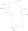
- the dust collection electrode 21 includes an electrode plate body 211 and a plurality of dust collection structures 212 provided on the electrode plate body 211.
- the dust collection structures 212 can increase the dust collection area of the dust collection electrode 21, which allows the dust collection electrode 21 to receive more accumulated dust.
- the generation electrode assembly 1 is arranged opposite to different dust collection structures 212. That is, each time the position and/or orientation state of one dust collection electrode 21 is changed, one dust collection structure 212 opposite to the generation electrode assembly 1 is replaced.
- one new dust collection structure 212 is arranged opposite to the generation electrode assembly 1 to accumulate dust, thereby further increasing a duration of a single use of the dust collection electrode assembly 2.
- the dust collection structure 212 may be any structure capable of increasing the dust collection area of the dust collection electrode 21.
- the dust collection structure 212 includes a protrusion disposed on a side edge of the electrode plate body 211.
- the protrusion extends in a direction same as the extension direction of the side edge.
- a cross section of the protrusion can be a part of a circle, which can further increase the dust collection area of the dust collection electrode 21.
- the part of the circle is obtained by cutting of a portion of the full circle, such as cutting a small portion of the full circle.
- the electrode plate body 211 includes a first side edge 2111 and a second side edge 2112 opposite to each other, and further includes a third side edge 2113 and a fourth side edge 2114 respectively connected to both ends of the first side edge 2111 and the both ends of the second side edge 2112.
- a plurality of dust collection structures 212 are respectively disposed on the first side edge 2111 and the second side edge 2112.
- a first protrusion 2121 is provided on the first side edge 2111 of the electrode plate body 211
- a second protrusion 2122 is provided on the second side edge 2112 of the electrode plate body 211.
- the dust collection electrode support structure includes a frame structure 22, and the dust collection electrode 21 can be provided in the frame structure 22 and be turnable around an axis parallel to the first side edge 2111, so that the dust collection electrode 21 can turn between a first position and a second position.
- the first position the first protrusion 2121 on the first side edge 2111 is opposite to the generation electrode assembly 1, and in this case, the first protrusion 2121 serves as the main dust collection structure 212 to collect the dust.
- the second protrusion 2122 on the second side edge 2112 is opposite to the generation electrode assembly 1, and in this case, the second protrusion 2122 serves as the main dust collection structure 212 to collect the dust.
- a rotating shaft is respectively provided on the third side edge 2113 and the fourth side 2114 of the dust collection electrode 21, and accordingly, the frame structure 22 is provided with rotating shaft holes (not shown in the figure) matching the rotating shaft.
- the rotating shaft is arranged rotatably in the rotating shaft holes to implement the turning of the dust collection electrode 21.
- rotating shaft holes are provided on the third side edge 2113 and the fourth side 2114 of the dust collection electrode 21, and accordingly, the frame structure 22 is provided with a rotating shaft (not shown in the figure) matching the rotating shaft holes.
- the rotating shaft is arranged rotatably in the rotating shaft holes to implement the turning of the dust collection electrode 21.
- the dust collection electrodes 21 need to be spaced apart to avoid interference between the dust collection electrodes 21 during the turning.
- the compactness of the structure is improved, for example, the rotating shaft or the rotating shaft holes is/are arranged at a midpoint of the third side edge 2113 and a midpoint of the fourth side edge 2114.
- the dust collection electrode 21 has a structure retractable in a direction parallel to the third side edge 2113.
- the dust collection electrode 21 is retracted when turning to avoid interference between the dust collection electrodes 21; after the turning is finished, the dust collection electrode 21 is stretched into an original shape and size.
- the dust collection electrode 21 can be retracted electrically; alternatively, the dust collection electrode 21 may include a fixed portion and a movable portion which is movable relative to the fixed portion, and the movable portion is in a normal position under an action of an offset member such as a spring, to maintain the original shape and size of the dust collection electrode 21; when the dust collection electrode 21 turns and interferes with a fixed portion of an adjacent dust collection electrode 21, the movable portion moves to a retraction position under an action of a force, and after the dust collection electrode 21 completes the turning, the movable portion returns to the normal position under the action of the offset member.
- the dust collection electrodes 21 having a retractable structure, the space between the dust collection electrodes 21 can also be reduced.
- the dust collection electrode assembly 2 further includes a drive device (not shown) configured to drive the dust collection electrode 21 to turn between the first position and the second position.
- the drive device may be, for example, a device capable of driving the dust collection electrode 21 to turn, such as a motor or a rotating cylinder, etc.
- the drive device may be provided at one end of the dust collection electrode 21 and mounted on the frame structure 22.
- the dust collection electrode assembly 2 further includes a transmission mechanism (not shown in the figures).
- the drive device drives a plurality of dust collection electrodes 21 to synchronously turn through the transmission mechanism.
- the transmission mechanism may be any transmission mechanism capable of rotating, such as a gear transmission mechanism, a double crank mechanism, and the like.
- the turning of the dust collection electrode 21 can be automatically controlled by the air purification device. For example, a cumulative working duration of the air purification device is calculated.
- the calculation method is that, if the dust collection electrode 21 in the air purification device is used for the first time, the cumulative working duration is calculated by taking time when the air purification device is turned on for the first time as a starting point; and if the dust collection electrode 21 in the air purification device is cleaned, the cumulative working duration is calculated by taking time when the air purification device is turned on for the first time after the dust collection electrode is cleaned as a starting point.
- the drive device is controlled to drive the dust collection electrode 21 to perform one turning.
- the cumulative working duration is greater than or equal to a second predetermined duration
- a prompt message is sent to the user to remind the user to clean the dust collection electrode 21.
- the cumulative working duration is reset to zero.
- the zero reset may be automatic, that is, when the air purification device detects that the dust collection electrode 21 is taken out and then reinstalled, it is determined that the dust collection electrode 21 has been cleaned, and the cumulative working duration is automatically reset to zero, or, the user can manually reset to zero.
- the first predetermined duration and the second predetermined duration can be set according to specific conditions.
- the first predetermined duration is, for example, a cleaning cycle of a conventional air purification device, and the second predetermined duration is less than or equal to twice the first predetermined time.
- a button portion (not shown in the figures) is provided on the air purification device, and the user can press the button portion to control the turning of the dust collection electrode 21 autonomously, for example, when the button portion is triggered, the drive device drives the dust collection electrode 21 to perform one turning.
- the button portion may be a mechanical button or a virtual button provided on a touch screen.
- the dust collection electrode assembly as a whole is configured to be able to move relative to the generation electrode assembly, thereby changing at least one of the position and orientation states of the dust collection electrode of the dust collection electrode assembly relative to the generation electrode assembly.
- the dust collection electrode assembly is configured to be able to turn integrally or be able to move integrally relative to the generation electrode assembly, and the configuration mode is similar to that of the foregoing dust collection electrode, which will not be repeated here again.
- the air purification device provided by the present invention further includes a primary effect filter screen 3 and an ozone reduction net 4.
- the primary effect filter screen 3, the generation electrode assembly 1, and the dust collection electrode assembly 2 and the ozone reduction net 4 are arranged in sequence.
- the air is preliminarily filtered through the primary effect filter screen 3 to extend the duration of a single use of the dust collection electrode assembly 2.
- the ozone produced by the air purification device during the air purification is decomposed by the ozone reduction net 4.
Landscapes
- Electrostatic Separation (AREA)
Abstract
Description
- The present application is based on and claims priority to Chinese patent application No.
201810578650.2, filed on June 7, 2018 - The present invention relates to the field of air purification technology, and particularly to a dust collection electrode assembly, an air purification device and a control method thereof.
- As the environmental problems become more and more serious, an air purifier has become a must-have household appliance for many families. The air purifier is usually divided into a filter type air purifier and an electrostatic type air purifier. The filter type air purifier uses a filter screen to filter particulate impurities such as PM2.5 and the like in the air. The filter screen in this type of air purifier needs to be regularly replaced, which increases the usage cost. The electrostatic type air purifier purifies the air in an electric purification mode, and there is no need to replace its consumables as long as its internal electrode plates are cleaned regularly, thereby saving the usage cost.
- Due to the high dust collection efficiency of the electrostatic air purifier, the dust collection capability of the electrode plate is easily weakened due to dust accumulation. Therefore, a user needs to frequently clean the electrode plate to ensure the purification effect of the purifier, which affects the user experience.
- According to an embodiment of the present invention, a dust collection electrode assembly applied to an air purification device is provided, the air purification device further includes a generation electrode assembly, the dust collection electrode assembly includes a dust collection electrode, the dust collection electrode is moveable to change at least one of a position state and an orientation state of the dust collection electrode relative to the generation electrode assembly.
- In an embodiment, the dust collection electrode assembly further includes a dust collection electrode support structure, the dust collection electrode is moveable relative to the dust collection electrode support structure.
- In an embodiment, the dust collection electrode assembly applied to an air purification device is provided, the air purification device further includes a generation electrode assembly, the dust collection electrode assembly includes a dust collection electrode and a dust collection electrode support structure, the dust collection electrode is moveable relative to the dust collection electrode support structure to change at least one of a position state and an orientation state of the dust collection electrode relative to the generation electrode assembly.
- In an embodiment, the dust collection electrode includes an electrode plate body and a plurality of dust collection structures provided on the electrode plate body, when the dust collection electrode is in different position states and/or orientation states relative to the generation electrode assembly, the generation electrode assembly is arranged opposite to different dust collection structures.
- In an embodiment, the plurality of dust collection structures are respectively provided on a first side edge and a second side edge of the electrode plate body, the first side edge is opposite to the second side edge.
- In an embodiment, a dust collection structure includes a protrusion provided on a side edge of the electrode plate body.
- In an embodiment, the protrusion extends in a direction same as an extension direction of the side edge, and a cross section of the protrusion is a portion of a circle.
- In an embodiment, the dust collection electrode support structure includes a frame structure, the dust collection electrode is provided in the frame structure and is turnable around an axis parallel to the first side edge, such that the dust collection electrode turnable between a first position and a second position; in the first position, a dust collection structure on the first side edge is opposite to the generation electrode assembly; and in the second position, a dust collection structure on the second side edge is opposite to the generation electrode assembly.
- In an embodiment, the electrode plate body further includes a third side edge and a fourth side edge connected to the first side edge and the second side edge, a rotating shaft is provided on the third side edge and the fourth side edge, the frame structure is provided with rotating shaft holes matching the rotating shaft; or rotating shaft holes are provided on the third side edge and the fourth side edge, the frame structure is provided with a rotating shaft matching the rotating shaft holes.
- In an embodiment, the dust collection electrode assembly further includes a drive device configured to drive the dust collection electrode to turn between the first position and the second position.
- In an embodiment, a plurality of dust collection electrodes are arranged side by side, the dust collection electrode assembly further includes a transmission mechanism, and the drive device drives the plurality of dust collection electrodes to turn synchronously through the transmission mechanism.
- In an embodiment, the transmission mechanism includes a gear transmission mechanism or a double crank mechanism.
- In an embodiment, the dust collection electrode has a retractable structure which is retractable in a direction parallel to the third side edge, the retractable structure is configured to retract when turning and stretch to an original shape and size after the turning is completed.
- In an embodiment, the dust collection electrode is retracted electrically; or
the dust collection electrode assembly further includes an offset member, the dust collection electrode includes a fixed portion and a movable portion which is movable relative to the fixed portion, when the dust collection electrode turns and interferes with a fixed portion of an adjacent dust collection electrode, the movable portion moves to a retraction position under an action of a force, and after the dust collection electrode completes turning, the movable portion returns to a normal position under an action of the offset member. - According to an embodiment, an air purification device is provided, which includes the above-mentioned dust collection electrode assembly.
- In an embodiment, the air purification device further includes a generation electrode assembly, the dust collection electrode assembly is moveable relative to the generation electrode assembly to change at least one of a position state and an orientation state of the dust collection electrode relative to the generation electrode assembly.
- According to an embodiment, a control method for the above-mentioned air purification device is provided, which includes:
calculating a cumulative working duration of the air purification device; - controlling the drive device to drive the dust collection electrode to perform one turning when the cumulative working duration is greater than or equal to a first predetermined duration; or, sending a prompt message to a user to remind the user to clean the dust collection electrode when the cumulative working duration is greater than or equal to a second predetermined duration.
- In an embodiment, the calculating the cumulative working duration of the air purification device includes:
- when the dust collection electrode in the air purification device is used for a first time, calculating the cumulative working duration by taking time when the air purification device is turned on for a first time as a starting point; and
- when the dust collection electrode in the air purification device is cleaned, calculating the cumulative working duration by taking time when the air purification device is turned on for the first time after the dust collection electrode is cleaned as the starting point.
- Through the following description of the embodiments of the present invention with reference to the accompanying drawings, the above and other purposes, features and advantages of the present invention will become clearer. In the drawings:
-
FIG. 1 is a schematic structure diagram illustrating a dust collection electrode assembly according to an embodiment of the present invention; -
FIG. 2 is a schematic structure diagram illustrating a dust collection electrode in a dust collection electrode assembly according to an embodiment of the present invention; and -
FIG. 3 is an exploded view of an air purification device according to an embodiment of the present invention. - The present invention is described below based on the embodiments, but the present invention is not limited to these embodiments. In order to avoid confusing the essence of the present invention, well-known methods, procedures, processes, and elements are not described in detail.
- In addition, those of ordinary skill in the art should understand that the drawings provided herein are for illustrative purpose, and the drawings are not necessarily drawn to scale.
- Unless the context clearly requires otherwise, the words "include", "comprise" and the like in the entire specification and claims should be interpreted as inclusive rather than exclusive or exhaustive, that is, "including but not limited to".
- In the description of the present invention, it should be appreciated that, terms "first", "second" and so on are used for descriptive purpose only, and cannot be understood as indicating or implying a relative importance. In addition, in the description of the present invention, unless otherwise stated, "a plurality of' means two or more.
- A purpose of the present invention is to provide a dust collection electrode assembly capable of effectively reducing the cleaning frequency, an air purification device having the dust collection electrode assembly, and a control method thereof.
- The dust collection electrode in the dust collection electrode assembly provided by the present invention is moveable relative to a dust collection electrode support structure, so that at least one of a position state and an orientation state of the dust collection electrode relative to the generation electrode assembly can be changed. By changing at least one of the position and orientation states of the dust collection electrode relative to the generation electrode assembly, a main dust accumulation area of the dust collection electrode can be changed. When there is more dust accumulated in a certain area, the position or orientation state of the dust collection electrode can be changed, so as to change to another area to accumulate the dust, thereby effectively reducing the cleaning frequency, slowing down the attenuation of the particulate matter CADR of the purification device, and optimizing the user experience.
- The present invention provides a dust collection electrode assembly and an air purification device having the dust collection electrode assembly, such as an electrostatic type air purifier. As shown in
FIG. 3 , the air purification device provided by the present invention includes ageneration electrode assembly 1 and a dust collection electrode assembly 2 opposite to each other. Thegeneration electrode assembly 1 includes ageneration electrode 11; the dust collection electrode assembly 2 includes adust collection electrode 21 and a dust collection electrode support structure. The dust collection electrode support structure is configured to support thedust collection electrode 21. After thegeneration electrode 11 is powered on, a high potential difference is formed between thegeneration electrode 11 and thedust collection electrode 21, accordingly a corona discharge can be produced, so that the particulate matter passing between thegeneration electrode 11 and thedust collection electrode 21 is charged, and the charged particulate matter moves to thedust collection electrode 21 and is accumulated on thedust collection electrode 21, thereby achieving the effect of air purification. - A main dust accumulation area of the
dust collection electrode 21 is a portion thereof opposite to thegeneration electrode 11. To solve the problem existing in the related art that thedust collection electrode 21 needs to be cleaned frequently to ensure the purification effect of the purification device, as shown inFIG. 1 andFIG. 2 , thedust collection electrode 21 in the dust collection electrode assembly 2 provided by the present invention is moveable relative to the dust collection electrode support structure, so that at least one of the position and/or orientation state of thedust collection electrode 21 relative to thegeneration electrode assembly 1 can be changed. By changing at least one of the position and/or orientation state of thedust collection electrode 21 relative to thegeneration electrode assembly 1, the main dust accumulation area of thedust collection electrode 21 can be changed. When there is more dust accumulated in a certain area, the position or orientation state of thedust collection electrode 21 can be changed, so as to change to another area to accumulate the dust, thereby effectively reducing the cleaning frequency, slowing down the attenuation of the particulate matter CADR of the purification device, and optimizing the user experience. The CADR is short for Clean Air Delivery Rate. - The mode of motion of the
dust collection electrode 21 relative to the dust collection electrode support structure may be, for example, translating and/or turning relative to the dust collection electrode support structure, such as turning relative to the dust collection electrode support structure. In such a way, the compactness of the overall structure of the air purification device is not affected, and the main dust accumulation area of thedust collection electrode 21 can be easily changed. - Further, as shown in
FIG. 2 , thedust collection electrode 21 includes anelectrode plate body 211 and a plurality of dust collection structures 212 provided on theelectrode plate body 211. The dust collection structures 212 can increase the dust collection area of thedust collection electrode 21, which allows thedust collection electrode 21 to receive more accumulated dust. When thedust collection electrode 21 is in different position and/or orientation states relative to thegeneration electrode assembly 1, thegeneration electrode assembly 1 is arranged opposite to different dust collection structures 212. That is, each time the position and/or orientation state of onedust collection electrode 21 is changed, one dust collection structure 212 opposite to thegeneration electrode assembly 1 is replaced. Thus, each time the position or orientation state of thedust collection electrode 21 is changed, one new dust collection structure 212 is arranged opposite to thegeneration electrode assembly 1 to accumulate dust, thereby further increasing a duration of a single use of the dust collection electrode assembly 2. - The dust collection structure 212 may be any structure capable of increasing the dust collection area of the
dust collection electrode 21. In some embodiments, the dust collection structure 212 includes a protrusion disposed on a side edge of theelectrode plate body 211. Preferably, the protrusion extends in a direction same as the extension direction of the side edge. Further, a cross section of the protrusion can be a part of a circle, which can further increase the dust collection area of thedust collection electrode 21. The part of the circle is obtained by cutting of a portion of the full circle, such as cutting a small portion of the full circle. - The
electrode plate body 211 includes afirst side edge 2111 and asecond side edge 2112 opposite to each other, and further includes athird side edge 2113 and afourth side edge 2114 respectively connected to both ends of thefirst side edge 2111 and the both ends of thesecond side edge 2112. In some embodiments, a plurality of dust collection structures 212 are respectively disposed on thefirst side edge 2111 and thesecond side edge 2112. For example, in the embodiment shown inFIG. 2 , a first protrusion 2121 is provided on thefirst side edge 2111 of theelectrode plate body 211, and asecond protrusion 2122 is provided on thesecond side edge 2112 of theelectrode plate body 211. In such a way, through the turning of thedust collection electrode 21, the dust collection structure 212 on thefirst side edge 2111 or the dust collection structure 212 on thesecond side edge 2112 can be arranged opposite to thegeneration electrode assembly 1. - Specifically, as shown in
FIG. 1 , the dust collection electrode support structure includes a frame structure 22, and thedust collection electrode 21 can be provided in the frame structure 22 and be turnable around an axis parallel to thefirst side edge 2111, so that thedust collection electrode 21 can turn between a first position and a second position. In the first position, the first protrusion 2121 on thefirst side edge 2111 is opposite to thegeneration electrode assembly 1, and in this case, the first protrusion 2121 serves as the main dust collection structure 212 to collect the dust. In the second position, thesecond protrusion 2122 on thesecond side edge 2112 is opposite to thegeneration electrode assembly 1, and in this case, thesecond protrusion 2122 serves as the main dust collection structure 212 to collect the dust. - A rotating shaft is respectively provided on the
third side edge 2113 and thefourth side 2114 of thedust collection electrode 21, and accordingly, the frame structure 22 is provided with rotating shaft holes (not shown in the figure) matching the rotating shaft. The rotating shaft is arranged rotatably in the rotating shaft holes to implement the turning of thedust collection electrode 21. Alternatively, rotating shaft holes are provided on thethird side edge 2113 and thefourth side 2114 of thedust collection electrode 21, and accordingly, the frame structure 22 is provided with a rotating shaft (not shown in the figure) matching the rotating shaft holes. The rotating shaft is arranged rotatably in the rotating shaft holes to implement the turning of thedust collection electrode 21. - In some embodiments, there are a plurality of
dust collection electrodes 21 arranged side by side. In order to implement that alldust collection electrodes 21 can turn at the same time, thedust collection electrodes 21 need to be spaced apart to avoid interference between thedust collection electrodes 21 during the turning. In order to minimize a space between thedust collection electrodes 21, the compactness of the structure is improved, for example, the rotating shaft or the rotating shaft holes is/are arranged at a midpoint of thethird side edge 2113 and a midpoint of thefourth side edge 2114. - In some other embodiments, the
dust collection electrode 21 has a structure retractable in a direction parallel to thethird side edge 2113. Thedust collection electrode 21 is retracted when turning to avoid interference between thedust collection electrodes 21; after the turning is finished, thedust collection electrode 21 is stretched into an original shape and size. Thedust collection electrode 21 can be retracted electrically; alternatively, thedust collection electrode 21 may include a fixed portion and a movable portion which is movable relative to the fixed portion, and the movable portion is in a normal position under an action of an offset member such as a spring, to maintain the original shape and size of thedust collection electrode 21; when thedust collection electrode 21 turns and interferes with a fixed portion of an adjacentdust collection electrode 21, the movable portion moves to a retraction position under an action of a force, and after thedust collection electrode 21 completes the turning, the movable portion returns to the normal position under the action of the offset member. By providing thedust collection electrodes 21 having a retractable structure, the space between thedust collection electrodes 21 can also be reduced. - In order to implement an automatic change of the position of the
dust collection electrode 21, in some embodiments, the dust collection electrode assembly 2 further includes a drive device (not shown) configured to drive thedust collection electrode 21 to turn between the first position and the second position. The drive device may be, for example, a device capable of driving thedust collection electrode 21 to turn, such as a motor or a rotating cylinder, etc. For example, the drive device may be provided at one end of thedust collection electrode 21 and mounted on the frame structure 22. - Further, in order to simplify the structure, the dust collection electrode assembly 2 further includes a transmission mechanism (not shown in the figures). The drive device drives a plurality of
dust collection electrodes 21 to synchronously turn through the transmission mechanism. The transmission mechanism may be any transmission mechanism capable of rotating, such as a gear transmission mechanism, a double crank mechanism, and the like. - The turning of the
dust collection electrode 21 can be automatically controlled by the air purification device. For example, a cumulative working duration of the air purification device is calculated. The calculation method is that, if thedust collection electrode 21 in the air purification device is used for the first time, the cumulative working duration is calculated by taking time when the air purification device is turned on for the first time as a starting point; and if thedust collection electrode 21 in the air purification device is cleaned, the cumulative working duration is calculated by taking time when the air purification device is turned on for the first time after the dust collection electrode is cleaned as a starting point. When the cumulative working duration is greater than or equal to a first predetermined duration, the drive device is controlled to drive thedust collection electrode 21 to perform one turning. When the cumulative working duration is greater than or equal to a second predetermined duration, a prompt message is sent to the user to remind the user to clean thedust collection electrode 21. When the user cleans thedust collection electrode 21 and puts it back into the air purification device, the cumulative working duration is reset to zero. Here, the zero reset may be automatic, that is, when the air purification device detects that thedust collection electrode 21 is taken out and then reinstalled, it is determined that thedust collection electrode 21 has been cleaned, and the cumulative working duration is automatically reset to zero, or, the user can manually reset to zero. The first predetermined duration and the second predetermined duration can be set according to specific conditions. The first predetermined duration is, for example, a cleaning cycle of a conventional air purification device, and the second predetermined duration is less than or equal to twice the first predetermined time. - In other embodiments, a button portion (not shown in the figures) is provided on the air purification device, and the user can press the button portion to control the turning of the
dust collection electrode 21 autonomously, for example, when the button portion is triggered, the drive device drives thedust collection electrode 21 to perform one turning. The button portion may be a mechanical button or a virtual button provided on a touch screen. - In an alternative embodiment, the dust collection electrode assembly as a whole is configured to be able to move relative to the generation electrode assembly, thereby changing at least one of the position and orientation states of the dust collection electrode of the dust collection electrode assembly relative to the generation electrode assembly. For example, the dust collection electrode assembly is configured to be able to turn integrally or be able to move integrally relative to the generation electrode assembly, and the configuration mode is similar to that of the foregoing dust collection electrode, which will not be repeated here again.
- Further, as shown in
FIG. 3 , the air purification device provided by the present invention further includes a primaryeffect filter screen 3 and an ozone reduction net 4. In a flow direction of the airflow, the primaryeffect filter screen 3, thegeneration electrode assembly 1, and the dust collection electrode assembly 2 and the ozone reduction net 4 are arranged in sequence. The air is preliminarily filtered through the primaryeffect filter screen 3 to extend the duration of a single use of the dust collection electrode assembly 2. The ozone produced by the air purification device during the air purification is decomposed by the ozone reduction net 4. - It is easy for those skilled in the art that to understand that the above preferred solutions can be freely combined or superimposed as long as they do not conflict with each other.
- It should be understood that the above embodiments are merely exemplary rather than restrictive. Those skilled in the art can make various apparent or equivalent modifications or substitutions to the above details without departing from the basic principles of the present invention, and these will all included in the scope of the claims of the present invention.
Claims (16)
- A dust collection electrode assembly, applied in an air purification device, the air purification device comprising a generation electrode assembly, wherein the dust collection electrode assembly comprises a dust collection electrode, the dust collection electrode is moveable to change at least one of a position state and an orientation state of the dust collection electrode relative to the generation electrode assembly.
- The dust collection electrode assembly according to claim 1, further comprising a dust collection electrode support structure, wherein the dust collection electrode is moveable relative to the dust collection electrode support structure.
- The dust collection electrode assembly according to claim 1 or 2, wherein the dust collection electrode comprises an electrode plate body and a plurality of dust collection structures provided on the electrode plate body, when the dust collection electrode is in different position states and/or orientation states relative to the generation electrode assembly, the generation electrode assembly is arranged opposite to different dust collection structures.
- The dust collection electrode assembly according to claim 3, wherein the plurality of dust collection structures are respectively provided on a first side edge and a second side edge of the electrode plate body, the first side edge is opposite to the second side edge.
- The dust collection electrode assembly according to claim 3, wherein a dust collection structure comprises a protrusion provided on a side edge of the electrode plate body.
- The dust collection electrode assembly according to claim 5, wherein the protrusion extends in a direction same as an extension direction of the side edge, and a cross section of the protrusion is a portion of a circle.
- The dust collection electrode assembly according to claim 4, further comprising a dust collection electrode support structure, wherein the dust collection electrode is capable of moving relative to the dust collection electrode support structure, the dust collection electrode support structure comprises a frame structure, the dust collection electrode is provided in the frame structure and is turnable around an axis parallel to the first side edge, such that the dust collection electrode is turnable between a first position and a second position; in the first position, a dust collection structure on the first side edge is opposite to the generation electrode assembly; and in the second position, a dust collection structure on the second side edge is opposite to the generation electrode assembly.
- The dust collection electrode assembly according to claim 7, wherein the electrode plate body further comprises a third side edge and a fourth side edge connected to the first side edge and the second side edge, a rotating shaft is provided on the third side edge and the fourth side edge, the frame structure is provided with rotating shaft holes matching the rotating shaft; or rotating shaft holes are provided on the third side edge and the fourth side edge, the frame structure is provided with a rotating shaft matching the rotating shaft holes.
- The dust collection electrode assembly according to claim 7, further comprising a drive device configured to drive the dust collection electrode to turn between the first position and the second position.
- The dust collection electrode assembly according to claim 9, further comprising a plurality of dust collection electrodes arranged side by side, wherein the dust collection electrode assembly further comprises a transmission mechanism, and the drive device drives the plurality of dust collection electrodes to turn synchronously through the transmission mechanism.
- The dust collection electrode assembly according to claim 10, wherein the transmission mechanism comprises a gear transmission mechanism or a double crank mechanism.
- The dust collection electrode assembly according to claim 8, wherein the dust collection electrode has a retractable structure which is retractable in a direction parallel to the third side edge, the retractable structure is configured to retract when turning and stretch to an original shape and size after the turning is completed.
- The dust collection electrode assembly according to claim 12, wherein,
the dust collection electrode is retracted electrically; or
the dust collection electrode assembly further comprises an offset member, the dust collection electrode comprises a fixed portion and a movable portion which is movable relative to the fixed portion, when the dust collection electrode turns and interferes with a fixed portion of an adjacent dust collection electrode, the movable portion moves to a retraction position under an action of a force, and after the dust collection electrode completes turning, the movable portion returns to a normal position under an action of the offset member. - An air purification device, comprising the dust collection electrode assembly according to any one of claims 1 to 13.
- A control method for an air purification device according to claim 14, wherein the dust collection electrode assembly further comprises a drive device configured to drive the dust collection electrode to turn between a first position and a second position, the control method comprises:calculating a cumulative working duration of the air purification device;controlling the drive device to drive the dust collection electrode to perform one turning when the cumulative working duration is greater than or equal to a first predetermined duration; or, sending a prompt message to a user to remind the user to clean the dust collection electrode when the cumulative working duration is greater than or equal to a second predetermined duration.
- The control method for the air purification device according to claim 15, wherein the calculating the cumulative working duration of the air purification device comprises:when the dust collection electrode in the air purification device is used for a first time, calculating the cumulative working duration by taking time when the air purification device is turned on for a first time as a starting point; andwhen the dust collection electrode in the air purification device is cleaned, calculating the cumulative working duration by taking time when the air purification device is turned on for the first time after the dust collection electrode is cleaned as the starting point.
Applications Claiming Priority (2)
| Application Number | Priority Date | Filing Date | Title |
|---|---|---|---|
| CN201810578650.2A CN108722674B (en) | 2018-06-07 | 2018-06-07 | Dust collecting electrode assembly, air purifying device and control method thereof |
| PCT/CN2018/121972 WO2019233082A1 (en) | 2018-06-07 | 2018-12-19 | Dust collection electrode assembly, air purification device and control method therefor |
Publications (2)
| Publication Number | Publication Date |
|---|---|
| EP3778033A1 true EP3778033A1 (en) | 2021-02-17 |
| EP3778033A4 EP3778033A4 (en) | 2021-10-13 |
Family
ID=63932719
Family Applications (1)
| Application Number | Title | Priority Date | Filing Date |
|---|---|---|---|
| EP18921673.2A Pending EP3778033A4 (en) | 2018-06-07 | 2018-12-19 | DUST COLLECTION ELECTRODE ASSEMBLY, AIR PURIFYING DEVICE AND RELATED CONTROL PROCEDURE |
Country Status (4)
| Country | Link |
|---|---|
| EP (1) | EP3778033A4 (en) |
| JP (1) | JP7210607B2 (en) |
| CN (1) | CN108722674B (en) |
| WO (1) | WO2019233082A1 (en) |
Families Citing this family (4)
| Publication number | Priority date | Publication date | Assignee | Title |
|---|---|---|---|---|
| CN108722674B (en) * | 2018-06-07 | 2019-09-20 | 珠海格力电器股份有限公司 | Dust collecting electrode assembly, air purifying device and control method thereof |
| CN111735151B (en) * | 2020-07-27 | 2025-04-18 | 珠海格力电器股份有限公司 | Dust collection module, door assembly and air purifier |
| CN112923498B (en) * | 2021-02-19 | 2022-06-28 | 合肥中科离子医学技术装备有限公司 | Low-temperature plasma air disinfection device with automatic intensity adjustment function |
| CN114484704A (en) * | 2021-12-03 | 2022-05-13 | 珠海格力电器股份有限公司 | Bionic electrode purification assembly and bionic electrode self-cleaning method |
Family Cites Families (17)
| Publication number | Priority date | Publication date | Assignee | Title |
|---|---|---|---|---|
| DE908370C (en) * | 1937-04-13 | 1954-04-05 | American Air Filter Co | Electric gas purifier |
| GB803152A (en) * | 1955-09-29 | 1958-10-22 | Metallgesellschaft Ag | Collecting electrodes for electrostatic precipitators |
| US4284420A (en) * | 1979-08-27 | 1981-08-18 | Borysiak Ralph A | Electrostatic air cleaner with scraper cleaning of collector plates |
| JPS60189345U (en) * | 1984-05-24 | 1985-12-14 | 日比野 進 | air purifier |
| US7150780B2 (en) * | 2004-01-08 | 2006-12-19 | Kronos Advanced Technology, Inc. | Electrostatic air cleaning device |
| WO2008068822A1 (en) * | 2006-12-01 | 2008-06-12 | Hitachi Plant Technologies, Ltd. | Moving electrode of electrostatic precipitator |
| JP2010000404A (en) * | 2008-06-18 | 2010-01-07 | Panasonic Corp | Electrostatic precipitation unit |
| JP5025777B2 (en) * | 2010-10-13 | 2012-09-12 | 三菱電機株式会社 | Air cleaner |
| JP2012125734A (en) * | 2010-12-17 | 2012-07-05 | Panasonic Corp | Outside air processing device |
| JP2013107050A (en) * | 2011-11-22 | 2013-06-06 | Panasonic Corp | Electrical dust collection device, and dust collection member |
| JP2014188383A (en) * | 2013-03-26 | 2014-10-06 | Hitachi Ltd | Dust collection plate in moving electrode type electric dust collector and production method of the same |
| CN206894986U (en) * | 2017-07-13 | 2018-01-16 | 珠海格力电器股份有限公司 | Plasma generator and purifier |
| CN207271438U (en) * | 2017-08-30 | 2018-04-27 | 珠海格力电器股份有限公司 | Electric purification structure and air purification device comprising same |
| CN108050587B (en) * | 2017-10-31 | 2020-05-29 | 青岛海尔智能技术研发有限公司 | Air purification device and control method thereof |
| CN108452946B (en) * | 2018-01-29 | 2024-04-12 | 珠海格力电器股份有限公司 | Air purifying device and cleaning method thereof |
| CN108722674B (en) * | 2018-06-07 | 2019-09-20 | 珠海格力电器股份有限公司 | Dust collecting electrode assembly, air purifying device and control method thereof |
| CN208177678U (en) * | 2018-06-07 | 2018-12-04 | 珠海格力电器股份有限公司 | Dust collection electrode assembly and air purification device |
-
2018
- 2018-06-07 CN CN201810578650.2A patent/CN108722674B/en active Active
- 2018-12-19 EP EP18921673.2A patent/EP3778033A4/en active Pending
- 2018-12-19 WO PCT/CN2018/121972 patent/WO2019233082A1/en not_active Ceased
- 2018-12-19 JP JP2020554859A patent/JP7210607B2/en active Active
Also Published As
| Publication number | Publication date |
|---|---|
| CN108722674A (en) | 2018-11-02 |
| JP7210607B2 (en) | 2023-01-23 |
| EP3778033A4 (en) | 2021-10-13 |
| JP2021517512A (en) | 2021-07-26 |
| CN108722674B (en) | 2019-09-20 |
| WO2019233082A1 (en) | 2019-12-12 |
Similar Documents
| Publication | Publication Date | Title |
|---|---|---|
| JP7210607B2 (en) | Dust collection electrode unit, air cleaner, and control method thereof | |
| CN103357222A (en) | Cleaning device of filter net of air purifier | |
| CN111195451A (en) | Continuous type dust collector for communication base station | |
| CN208177678U (en) | Dust collection electrode assembly and air purification device | |
| CN118356727A (en) | A filtering device for sewage treatment | |
| CN211011867U (en) | A filter screen, filter screen assembly and air conditioner | |
| CN215000214U (en) | Mobile robot with automatic regulating function | |
| CN108176139A (en) | Filter screen cleaning mechanism and air conditioner | |
| JP3807451B2 (en) | Air conditioner | |
| CN210146236U (en) | Cleaning structure and air purifier | |
| CN206469365U (en) | A kind of clarifier moving structure | |
| CN103908195A (en) | Vacuum dust collector and cleaning method for filtering device thereof | |
| CN113418269A (en) | Energy-concerving and environment-protective type air purifier | |
| CN209735174U (en) | Air conditioner purification and filtration device for dust-free workshop | |
| CN208612083U (en) | A kind of electrostatic field rolling shutter air purification equipment | |
| CN113617655B (en) | Roller screen with variable diameter | |
| CN211411370U (en) | Electronic dust removal device | |
| WO2013021378A1 (en) | Bipolar ion generator with cleaning of ionizing electrodes | |
| CN107875741A (en) | A kind of air filtration core cleaning device of efficiency high | |
| CN110772901A (en) | Electronic dust removal device | |
| CN111536621A (en) | Air purifier with monitoring function | |
| CN217594142U (en) | Refrigerating system filtration convenient to dismantle and change | |
| CN209702961U (en) | An internal cleaning device for a texturing machine heat box | |
| CN106196324A (en) | A purifier mobile structure and control method thereof | |
| CN213943914U (en) | A filter cleaning device for a screening machine |
Legal Events
| Date | Code | Title | Description |
|---|---|---|---|
| STAA | Information on the status of an ep patent application or granted ep patent |
Free format text: STATUS: THE INTERNATIONAL PUBLICATION HAS BEEN MADE |
|
| PUAI | Public reference made under article 153(3) epc to a published international application that has entered the european phase |
Free format text: ORIGINAL CODE: 0009012 |
|
| STAA | Information on the status of an ep patent application or granted ep patent |
Free format text: STATUS: REQUEST FOR EXAMINATION WAS MADE |
|
| 17P | Request for examination filed |
Effective date: 20201102 |
|
| AK | Designated contracting states |
Kind code of ref document: A1 Designated state(s): AL AT BE BG CH CY CZ DE DK EE ES FI FR GB GR HR HU IE IS IT LI LT LU LV MC MK MT NL NO PL PT RO RS SE SI SK SM TR |
|
| AX | Request for extension of the european patent |
Extension state: BA ME |
|
| RIC1 | Information provided on ipc code assigned before grant |
Ipc: B03C 3/47 20060101AFI20210512BHEP Ipc: B03C 3/011 20060101ALI20210512BHEP Ipc: B03C 3/019 20060101ALI20210512BHEP Ipc: B03C 3/08 20060101ALI20210512BHEP Ipc: B03C 3/10 20060101ALI20210512BHEP Ipc: B03C 3/86 20060101ALI20210512BHEP Ipc: B03C 3/12 20060101ALI20210512BHEP |
|
| DAV | Request for validation of the european patent (deleted) | ||
| DAX | Request for extension of the european patent (deleted) | ||
| A4 | Supplementary search report drawn up and despatched |
Effective date: 20210909 |
|
| RIC1 | Information provided on ipc code assigned before grant |
Ipc: B03C 3/12 20060101ALI20210903BHEP Ipc: B03C 3/86 20060101ALI20210903BHEP Ipc: B03C 3/10 20060101ALI20210903BHEP Ipc: B03C 3/08 20060101ALI20210903BHEP Ipc: B03C 3/019 20060101ALI20210903BHEP Ipc: B03C 3/011 20060101ALI20210903BHEP Ipc: B03C 3/47 20060101AFI20210903BHEP |
|
| P01 | Opt-out of the competence of the unified patent court (upc) registered |
Effective date: 20230530 |
|
| STAA | Information on the status of an ep patent application or granted ep patent |
Free format text: STATUS: EXAMINATION IS IN PROGRESS |
|
| 17Q | First examination report despatched |
Effective date: 20231214 |