EP3777957B1 - Medical connection structure - Google Patents
Medical connection structure Download PDFInfo
- Publication number
- EP3777957B1 EP3777957B1 EP19868858.2A EP19868858A EP3777957B1 EP 3777957 B1 EP3777957 B1 EP 3777957B1 EP 19868858 A EP19868858 A EP 19868858A EP 3777957 B1 EP3777957 B1 EP 3777957B1
- Authority
- EP
- European Patent Office
- Prior art keywords
- engageable
- cylinder
- threadedly
- threadedly engageable
- male
- Prior art date
- Legal status (The legal status is an assumption and is not a legal conclusion. Google has not performed a legal analysis and makes no representation as to the accuracy of the status listed.)
- Active
Links
Images





Classifications
-
- F—MECHANICAL ENGINEERING; LIGHTING; HEATING; WEAPONS; BLASTING
- F16—ENGINEERING ELEMENTS AND UNITS; GENERAL MEASURES FOR PRODUCING AND MAINTAINING EFFECTIVE FUNCTIONING OF MACHINES OR INSTALLATIONS; THERMAL INSULATION IN GENERAL
- F16L—PIPES; JOINTS OR FITTINGS FOR PIPES; SUPPORTS FOR PIPES, CABLES OR PROTECTIVE TUBING; MEANS FOR THERMAL INSULATION IN GENERAL
- F16L19/00—Joints in which sealing surfaces are pressed together by means of a member, e.g. a swivel nut, screwed on, or into, one of the joint parts
- F16L19/005—Joints in which sealing surfaces are pressed together by means of a member, e.g. a swivel nut, screwed on, or into, one of the joint parts comprising locking means for the threaded member
-
- A—HUMAN NECESSITIES
- A61—MEDICAL OR VETERINARY SCIENCE; HYGIENE
- A61M—DEVICES FOR INTRODUCING MEDIA INTO, OR ONTO, THE BODY; DEVICES FOR TRANSDUCING BODY MEDIA OR FOR TAKING MEDIA FROM THE BODY; DEVICES FOR PRODUCING OR ENDING SLEEP OR STUPOR
- A61M39/00—Tubes, tube connectors, tube couplings, valves, access sites or the like, specially adapted for medical use
- A61M39/10—Tube connectors or tube couplings
- A61M39/1011—Locking means for securing connection; Additional tamper safeties
-
- F—MECHANICAL ENGINEERING; LIGHTING; HEATING; WEAPONS; BLASTING
- F16—ENGINEERING ELEMENTS AND UNITS; GENERAL MEASURES FOR PRODUCING AND MAINTAINING EFFECTIVE FUNCTIONING OF MACHINES OR INSTALLATIONS; THERMAL INSULATION IN GENERAL
- F16L—PIPES; JOINTS OR FITTINGS FOR PIPES; SUPPORTS FOR PIPES, CABLES OR PROTECTIVE TUBING; MEANS FOR THERMAL INSULATION IN GENERAL
- F16L19/00—Joints in which sealing surfaces are pressed together by means of a member, e.g. a swivel nut, screwed on, or into, one of the joint parts
- F16L19/02—Pipe ends provided with collars or flanges, integral with the pipe or not, pressed together by a screwed member
- F16L19/025—Pipe ends provided with collars or flanges, integral with the pipe or not, pressed together by a screwed member the pipe ends having integral collars or flanges
-
- A—HUMAN NECESSITIES
- A61—MEDICAL OR VETERINARY SCIENCE; HYGIENE
- A61M—DEVICES FOR INTRODUCING MEDIA INTO, OR ONTO, THE BODY; DEVICES FOR TRANSDUCING BODY MEDIA OR FOR TAKING MEDIA FROM THE BODY; DEVICES FOR PRODUCING OR ENDING SLEEP OR STUPOR
- A61M39/00—Tubes, tube connectors, tube couplings, valves, access sites or the like, specially adapted for medical use
- A61M39/10—Tube connectors or tube couplings
- A61M2039/1083—Tube connectors or tube couplings having a plurality of female connectors, e.g. Luer connectors
-
- A—HUMAN NECESSITIES
- A61—MEDICAL OR VETERINARY SCIENCE; HYGIENE
- A61M—DEVICES FOR INTRODUCING MEDIA INTO, OR ONTO, THE BODY; DEVICES FOR TRANSDUCING BODY MEDIA OR FOR TAKING MEDIA FROM THE BODY; DEVICES FOR PRODUCING OR ENDING SLEEP OR STUPOR
- A61M39/00—Tubes, tube connectors, tube couplings, valves, access sites or the like, specially adapted for medical use
- A61M39/10—Tube connectors or tube couplings
- A61M2039/1088—Tube connectors or tube couplings having a plurality of male connectors, e.g. Luer connectors
-
- A—HUMAN NECESSITIES
- A61—MEDICAL OR VETERINARY SCIENCE; HYGIENE
- A61M—DEVICES FOR INTRODUCING MEDIA INTO, OR ONTO, THE BODY; DEVICES FOR TRANSDUCING BODY MEDIA OR FOR TAKING MEDIA FROM THE BODY; DEVICES FOR PRODUCING OR ENDING SLEEP OR STUPOR
- A61M2205/00—General characteristics of the apparatus
- A61M2205/02—General characteristics of the apparatus characterised by a particular materials
- A61M2205/0216—Materials providing elastic properties, e.g. for facilitating deformation and avoid breaking
-
- A—HUMAN NECESSITIES
- A61—MEDICAL OR VETERINARY SCIENCE; HYGIENE
- A61M—DEVICES FOR INTRODUCING MEDIA INTO, OR ONTO, THE BODY; DEVICES FOR TRANSDUCING BODY MEDIA OR FOR TAKING MEDIA FROM THE BODY; DEVICES FOR PRODUCING OR ENDING SLEEP OR STUPOR
- A61M39/00—Tubes, tube connectors, tube couplings, valves, access sites or the like, specially adapted for medical use
- A61M39/10—Tube connectors or tube couplings
- A61M39/1033—Swivel nut connectors, e.g. threaded connectors or bayonet-connectors
Definitions
- the torque limiting mechanism is disposed between the threadedly engageable cylinder and an operation cylinder mounted on an outer periphery of the threadedly engageable cylinder.
- the torque limiting mechanism transmits a rotary torque of the operation cylinder in a tightening direction to the threadedly engageable cylinder.
- the torque limiting mechanism allows the operation cylinder to be turned idly with respect to the threadedly engageable cylinder when the rotary torque exceeds a predetermined torque. Thereby, the excessive tightening by the threadedly engageable cylinder can be prevented.
- a dimension of the engageable claw in the axial direction can be longer than the slit. In this case, the predetermined torque can be set higher.
- the ratchet teeth of the loosening prevention mechanism are formed in an inner periphery of the mounting portion of the threadedly engageable cylinder, the ratchet teeth disposed adjacent to the elastically deformable portion of the torque limiting mechanism in the axial direction; the elastic leaf of the loosening prevention mechanism is formed in the support portion of the male connector; and the second engageable claw is protruded outward in the radial direction and engaged with the ratchet teeth.
- the female connector 2 is brought closer to the male assembly 1 having the features mentioned above and the male luer portion 11 is inserted into the female luer portion 2a. The insertion proceeds without resistance until the engageable protrusions 2c of the female connector 2 are abutted against the female screw 21a of the threadedly engageable cylinder 20 of the male assembly 1.
- the operation cylinder 30 is turned in the loosening direction L. Then, in the torque limiting mechanism 50, the steep surfaces 53b of the engageable claws 53 of the threadedly engageable cylinder 20 are abutted against the steep surfaces 51b of the corresponding teeth of the engageable teeth 51 of the operation cylinder 30, and the threadedly engageable cylinder 20 is rotated in the loosening direction together with the operation cylinder 30.
- the elastically deformable portion 52 of the torque limiting mechanism 50 is adjacent to the slit 54 composed only of the straight portion and has a high elastic coefficient as mentioned above, the torque (predetermined torque) at which the operation cylinder 30 starts the idle turning can be set adequately high.
- FIG. 11 shows a modification in which only one engageable claw 53 is disposed adjacent to a slit 54 in each of elastically deformable portions 52. In this case, a predetermined torque is lower than the one in the first embodiment.
- FIG. 12 shows a modification in which only one engageable claw 53 is disposed spaced from a slit 54 in each of elastically deformable portions 52.
- a predetermined torque is higher than the one in the modification of FIG. 11 but lower than the one in the first embodiment.
- FIG. 13 shows a modification in which two engageable claws 53 are disposed spaced from a slit 54 in each of elastically deformable portions 52.
- a predetermined torque is higher than the one in the first embodiment.
- an area adjacent to the slit 54 on a tightening direction side is provided as the elastically deformable portion 52.
- the loosening prevention mechanism may be omitted.
- areas in opposite sides of the slit in the circumferential direction may be provided as the elastically deformable portions.
- the support portion and the coupling portion of the male connector may be separate from each other and rotatable with respect to each other.
- the present invention may be applied for connecting a three-way stopcock and a tube.
- the present invention may be applied for connecting various kinds of medical components.
- the present invention may be applied to connecting structures for medical use.
Landscapes
- Health & Medical Sciences (AREA)
- Engineering & Computer Science (AREA)
- Heart & Thoracic Surgery (AREA)
- General Engineering & Computer Science (AREA)
- Anesthesiology (AREA)
- Biomedical Technology (AREA)
- Hematology (AREA)
- Life Sciences & Earth Sciences (AREA)
- Animal Behavior & Ethology (AREA)
- General Health & Medical Sciences (AREA)
- Public Health (AREA)
- Veterinary Medicine (AREA)
- Pulmonology (AREA)
- Mechanical Engineering (AREA)
- Infusion, Injection, And Reservoir Apparatuses (AREA)
- Joints With Pressure Members (AREA)
Description
- The present invention relates to a connecting structure for medical use for connecting medical components such as tubes.
- There are various types of connecting structures for medical use. A connecting structure for medical use of the kind disclosed in
Patent Document 1 to be described later includes a male assembly and a female connector. Further examples of connecting structures are described inUS 2013/0076030 andUS 2014/0265312 . - The male assembly includes a male connector and a threadedly engageable cylinder rotatably attached to the male connector. The male connector includes a male luer portion having a tapered outer periphery. The threadedly engageable cylinder includes a threadedly engageable portion disposed outside of the male luer portion in a radial direction. A female screw is formed in an inner periphery of the threadedly engageable portion.
- The female connector includes a female luer portion having a tapered inner periphery. Engageable protrusions threadedly engageable with the female screw are formed in an outer periphery of a distal end portion of the female luer portion.
- When the threadedly engageable cylinder is turned in a tightening direction in a state where the female screw of the threadedly engageable cylinder and the engageable protrusions of the female connector are threadedly engaged with each other, the male luer portion and the female luer portion are joined. When the threadedly engageable cylinder is turned further in the tightening direction, the male luer portion and the female luer portion are tightly joined with a pressing force working therebetween, providing sufficient sealing properties.
- In the connecting structure for medical use of
Patent Document 1, an excessive force may be applied to join the male luer portion and the female luer portion by excessive tightening by the threadedly engageable cylinder. - To solve the problem mentioned above, the inventors of the present application developed a connecting structure for medical use including a torque limiting mechanism as disclosed in
Patent Document 2 to be described later. - The torque limiting mechanism is disposed between the threadedly engageable cylinder and an operation cylinder mounted on an outer periphery of the threadedly engageable cylinder. The torque limiting mechanism transmits a rotary torque of the operation cylinder in a tightening direction to the threadedly engageable cylinder. The torque limiting mechanism allows the operation cylinder to be turned idly with respect to the threadedly engageable cylinder when the rotary torque exceeds a predetermined torque. Thereby, the excessive tightening by the threadedly engageable cylinder can be prevented.
- The torque limiting mechanism includes engageable teeth formed in the outer periphery of the threadedly engageable cylinder over an entire periphery and engageable claws formed in an inner periphery of an end portion of the operation cylinder, the engageable claws being engageable with the engageable teeth. A lot of slits extending in an axial direction from an end of the operation cylinder are formed in the end portion of the operation cylinder. Areas between the slits are provided as elastic leaves. The engageable claws are formed in the elastic leaves.
-
- Patent Document 1:
Japanese Utility Model Application Publication No. S59-87840 - Patent Document 2: International Patent Application Publication No.
WO2016/157974 - Patent Document 3:
Japanese Patent Application Publication No. 2010-527276 - In the connecting structure for medical use including the torque limiting mechanism disclosed in
Patent Document 2, the torque limiting mechanism is not protected from dust. The elastic leaf including the engageable claw is defined on three sides by two slits and an end edge of the operation cylinder. Therefore, an elastic coefficient of the elastic leaf is relatively low, and the predetermined torque at which the operation cylinder starts the idle turning cannot be set adequately high according to necessity. - The connecting structure for medical use disclosed in FIGS. 73 to 75 of Patent Document 3 includes a loosening prevention mechanism disposed between a male connector and a threadedly engageable cylinder, but fails to include a torque limiting mechanism.
- To solve the problems mentioned above, the present invention provides a connecting structure for medical use as defined in
claim 1. The connecting structure according to the present disclosure includes a male assembly and a female connector of a cylindrical configuration, the male assembly including a male connector of a cylindrical configuration and a threadedly engageable cylinder rotatably coupled to the male connector, - the male connector including a male luer portion and a support portion arranged in a direction from a distal end to a basal end thereof in this order,
- the threadedly engageable cylinder including a threadedly engageable portion and a mounting portion arranged in a direction from a distal end to a basal end thereof in this order, the mounting portion rotatably mounted on an outer periphery of the support portion of the male connector, the threadedly engageable portion including a female screw in an inner periphery thereof, the threadedly engageable portion disposed outside of the male luer portion in a radial direction,
- the female connector including a female luer portion and an engageable protrusion formed in an outer periphery of the female luer portion,
- the male luer portion and the female luer portion joined by turning the threadedly engageable cylinder in a tightening direction in a state where the female screw of the threadedly engageable cylinder and the engageable protrusion of the female connector are threadedly engaged with each other,
- the connecting structure further including an operation cylinder mounted on an outer periphery of the threadedly engageable cylinder and a torque limiting mechanism disposed between the threadedly engageable cylinder and the operation cylinder, the torque limiting mechanism transmitting a rotary torque of the operation cylinder in a tightening direction to the threadedly engageable cylinder, the torque limiting mechanism allowing the operation cylinder to be turned idly with respect to the threadedly engageable cylinder when the rotary torque exceeds a predetermined torque,
- the torque limiting mechanism including engageable teeth formed in an inner periphery of one end portion of the operation cylinder in an axial direction over an entire periphery and at least one first engageable claw protruded outward in a radial direction from an outer surface of one end portion of the threadedly engageable cylinder in an axial direction, the first engageable claw engageable with the engageable teeth, wherein at least one slit is formed in the one end portion of the threadedly engageable cylinder, the slit composed only of a straight portion extending in the axial direction from an end of the threadedly engageable cylinder, at least one of two areas of the one end portion of the threadedly engageable cylinder adjacent to the slit in a circumferential direction is provided as an elastically deformable portion having a lower elastic coefficient than the other areas of the one end portion of the threadedly engageable cylinder, the first engageable claw is formed in an outer surface of the elastically deformable portion, and
- the elastically deformable portion is deformed inward in the radial direction when the operation cylinder is turned idly and the first engageable claw is moved over the engageable teeth.
- According to the features mentioned above, the torque limiting mechanism that prohibits the excessive tightening by the threadedly engageable cylinder can be covered by the operation cylinder, thereby protecting the torque limiting mechanism from dust.
- Furthermore, since the area adjacent to the slit composed only of the straight portion is provided as the elastically deformable portion, the torque (predetermined torque) at which the operation cylinder starts the idle turning can be set adequately high. It is because since the elastically deformable portion is defined on two sides by the slit and an end edge of the threadedly engageable cylinder, an elastic coefficient of the elastically deformable portion can be higher than that of an elastically deformable portion that is defined on three sides, for example.
- Preferably, a dimension of the first engageable claw in the axial direction is shorter than that of the slit. According to the features mentioned above, a major portion of the engageable claw can be disposed in the area provided as the elastically deformable portion. Therefore, the engageable claw can be smoothly moved over the engageable teeth when the operation cylinder is turned idly.
- A dimension of the engageable claw in the axial direction can be longer than the slit. In this case, the predetermined torque can be set higher.
- Locations and the number of the engageable claws can be determined according to a required predetermined torque. Specifically, a predetermined torque is higher when the enageable claw is located spaced from the slit in a circumferential direction than when the engageable claw is located adjacent to the slit. The predetermined torque is increased as the number of the engageable claws is increased.
- Preferably, a loosening prevention mechanism is disposed between the support portion of the male connector and the mounting portion of the threadedly engageable cylinder, the loosening prevention mechanism prohibiting the threadedly engageable cylinder from being rotated in a loosening direction with respect to the male connector in a state where the male luer portion and the female luer portion are joined;
- the loosening prevention mechanism includes ratchet teeth formed in one of the support portion of the male connector and the mounting portion of the threadedly engageable cylinder over an entire periphery, at least one elastic leaf formed in the other of the support portion and the mounting portion and a second engageable claw formed in the elastic leaf and engageable with the ratchet teeth; and
- the elastic coefficient of the elastically deformable portion of the torque limiting mechanism is higher than an elastic coefficient of the elastic leaf of the loosening prevention mechanism.
- According to the features mentioned above, the threadedly engageable cylinder is prohibited from being turned in the loosening direction with respect to the male connector in the state where the male luer portion and the female luer portion are joined. Therefore, sealing properties between the male luer portion and the female luer portion can be maintained, thereby surely preventing leakage of fluid. The loosening prevention mechanism does not interfere with actions of the torque limiting mechanism.
- Preferably, the ratchet teeth of the loosening prevention mechanism are formed in an inner periphery of the mounting portion of the threadedly engageable cylinder, the ratchet teeth disposed adjacent to the elastically deformable portion of the torque limiting mechanism in the axial direction; the elastic leaf of the loosening prevention mechanism is formed in the support portion of the male connector; and the second engageable claw is protruded outward in the radial direction and engaged with the ratchet teeth.
- According to the present invention, the torque limiting mechanism can be protected from dust. Furthermore, the torque (predetermined torque) at which the operation cylinder starts the idle turning can be set adequately high.
-
-
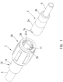
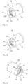
FIG. 1 is a perspective view of a connecting structure for medical use according to one embodiment of the present invention, with a male assembly and a female connector shown in a separate state. -
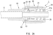
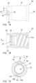
FIG. 2A is a longitudinal sectional view of the male assembly. -
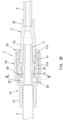
FIG. 2B is a longitudinal sectional view of the connecting structure for medical use, with the male assembly and the female connector shown in a joined state. -
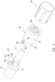
FIG. 3 is an exploded perspective view of the male assembly. -
FIG. 4 is a perspective view of the male assembly, viewed from a different direction from that ofFIG. 1 . -
FIG. 5 is an exploded perspective view of the male assembly shown inFIG. 4 . -
FIG. 6A is a plan view of a male connector of the male assembly. -
FIG. 6B is a cross-sectional view taken along line B-B ofFIG. 6A . -
FIG. 6C is a cross-sectional view taken along line C-C ofFIG. 6B . -
FIG. 7A is a plan view of a threadedly engageable cylinder of the male assembly. -
FIG. 7B is a cross-sectional view taken along line B-B ofFIG. 7A . -
FIG. 7C is a view from direction C ofFIG. 7B . -
FIG. 8A is a longitudinal sectional view of an operation cylinder of the male assembly. -
FIG. 8B is a view from direction B ofFIG. 8A . -
FIG. 9 is a cross-sectional view taken along line IX-IX ofFIG. 2B . -
FIG. 10A is an enlarged cross-sectional view of a major portion of a loosening prevention mechanism ofFIG. 9 in a state where a rotary torque is not applied to the threadedly engageable cylinder. -
FIG. 10B is an enlarged cross-sectional view of the major portion of the loosening prevention mechanism in a state where a rotary torque in a tightening direction is applied to the threadedly engageable cylinder. -
FIG. 10C is an enlarged cross-sectional view of the major portion of the loosening prevention mechanism in a state where a rotary torque in a loosening direction is applied to the threadedly engageable cylinder. -
FIG. 11 is a perspective view of a modification example of the threadedly engageable cylinder. -
FIG. 12 is a perspective view of another modification example of the threadedly engageable cylinder. -
FIG. 13 is a perspective view of still another modification example of the threadedly engageable cylinder. -
FIG. 14 is a plan view of yet another modification example of the threadedly engageable cylinder. - A connecting structure for medical use according to a first embodiment of the present invention will be described hereinafter with reference to
FIGS. 1 to 10 . - As shown in
FIG. 1 , the connecting structure for medical use includes amale assembly 1 and afemale connector 2. Themale assembly 1 and thefemale connector 2 cooperate to connecttubes 5, 5' (first and second medical components) in which liquid such as medical solution and blood is to be flown. Components of themale assembly 1 and thefemale connector 2 are made of resin. - The
female connector 2 having a simpler structure will be described first with reference toFIGS. 1 and2B . Thefemale connector 2 having a thin and long cylindrical configuration includes afemale luer portion 2a in one end portion (distal end portion) thereof in an axial direction and acoupling portion 2b in the other end portion (basal end portion) thereof. An inner surface of thefemale luer portion 2a has a gently tapered configuration whose diameter is gradually increased towards a distal end thereof. A pair ofengageable protrusions 2c that work as male screws are formed in an outer periphery of a distal end portion of thefemale luer portion 2a 180 degrees apart from each other in a circumferential direction. An end portion of the tube 5' is to be inserted into and fixed at thecoupling portion 2b. - As shown in
FIGS. 2A ,3 and5 , themale assembly 1 includes amale connector 10, a threadedlyengageable cylinder 20 and anoperation cylinder 30. The threadedly engageablecylinder 20 is mounted on an outer periphery of themale connector 10 such that the threadedly engageablecylinder 20 is rotatable but immovable in an axial direction. Theoperation cylinder 30 is mounted on an outer periphery of the threadedly engageablecylinder 20 such that theoperation cylinder 30 is rotatable but immovable in the axial direction. - As shown in
FIG. 6 , themale connector 10 has a thin and long cylindrical configuration. Themale connector 10 includes amale luer portion 11 in one end portion (distal end portion) thereof in an axial direction, acoupling portion 12 in the other end portion (basal end portion) thereof and asupport portion 13 in a middle portion thereof. An outer surface of themale luer portion 11 has a gently tapered configuration whose diameter is gradually reduced towards a distal end thereof. A taper angle of the outer surface of themale luer portion 11 and a taper angle of the inner surface of thefemale luer portion 2a are substantially the same. An end portion of thetube 5 is to be inserted into and fixed at thecoupling portion 12. - As shown in
FIG. 7 , the threadedly engageablecylinder 20 includes a threadedlyengageable portion 21 in one end portion (distal end portion) thereof in the axial direction and a mountingportion 22 in the other end portion (basal end portion) thereof. Afemale screw 21a is formed in an inner periphery of the threadedly engageableportion 21. As shown inFIG. 2A , the mountingportion 22 is mounted on thesupport portion 13 of themale connector 10 such that the mountingportion 22 is rotatable but immovable in the axial direction. - As shown in
FIGS. 1 and2A , in a state where the threadedly engageablecylinder 20 is mounted on themale connector 10, the threadedly engageableportion 21 of the threadedly engageablecylinder 20 is disposed outside of themale luer portion 11 in a radial direction and anannular insertion space 25 is formed between the threadedlyengageable portion 21 and themale luer portion 11. Anannular gap 26 is formed between a small-diameter portion of thesupport portion 13 of themale connector 10 and the mountingportion 22 of the threadedly engageablecylinder 20. - As shown in
FIG. 2A , themale assembly 1 includes aloosening prevention mechanism 40 disposed in theannular gap 26. Theloosening prevention mechanism 40 includes ratchet teeth 41and a pair of elastic leaves 42. As shown inFIGS. 5 and7 , theratchet teeth 41 are formed in an inner periphery of the mountingportion 22 of the threadedly engageablecylinder 20 over an entire periphery. As shown inFIGS. 3 and6 , the elastic leaves 42 are formed in the small-diameter portion of thesupport portion 13 of themale connector 10. - The
ratchet teeth 41 are formed in the mountingportion 22 of the threadedly engageablecylinder 20 at a portion distanced away from a basal end of the mountingportion 22 through a predetermined distance. As shown inFIG. 10A , each tooth of theratchet teeth 41 includes aninclined surface 41a on a tightening direction T side to be described later and asteep surface 41b on a loosening direction L side. - The small-diameter portion of the
support portion 13 of themale connector 10 has a pair of chamferedflat surfaces 13x formed in an outer cylindrical periphery thereof. The pair offlat surfaces 13x are opposed to each other in the radial direction and extend parallel to each other. - A
support protrusion 44 is protruded outward in the radial direction from an end portion of theflat surface 13x of thesupport portion 13 in a circumferential direction (end portion on the loosening direction L side). Theelastic leaf 42 extends from a distal end ofsupport protrusion 44 in the tightening direction T (circumferential direction) generally in parallel to theflat surface 13x. Thesupport protrusion 44 and theelastic leaf 42 are arranged in a generally L-shaped configuration. Theelastic leaf 42 is spaced from theflat surface 13x. Anengageable claw 43 protruded outward in the radial direction is formed in a distal end (free end) of theelastic leaf 42. - As shown in
FIGS. 9 and10A , the pair ofengageable claws 43 are engaged with theratchet teeth 41. Theengageable claw 43 includes aninclined surface 43a on the loosening direction L side and asteep surface 43b on the tightening direction T side. Theinclined surface 43a of theengageable claw 43 is opposed to theinclined surface 41a of the corresponding tooth of theratchet teeth 41 in the circumferential direction and thesteep surfaces - As shown in
FIG. 2A , themale assembly 1 of this embodiment also includes atorque limiting mechanism 50 disposed between the threadedlyengageable cylinder 20 and theoperation cylinder 30. Thetorque limiting mechanism 50 includesengageable teeth 51 and a pair of elasticallydeformable portions 52. As shown inFIGS. 5 and8 , theengageable teeth 51 are formed in an inner periphery of a basal end portion of theoperation cylinder 30 over an entire periphery. As shown inFIGS. 3 ,5 and7 , the elasticallydeformable portions 52 are formed in the basal end portion of the threadedly engageablecylinder 20. - As shown in
FIGS. 8 and 9 , each tooth of theengageable teeth 51 includes aninclined surface 51a on the tightening direction T side and asteep surface 51b on the loosening direction L side as with theratchet teeth 41 of theloosening prevention mechanism 40. - As shown in
FIGS. 3 ,5 and7 , a pair ofslits 54 are formed in an end portion of the mountingportion 22 of the threadedly engageablecylinder 20 180 degrees apart from each other in the circumferential direction. Theslit 54 composed only of a straight portion extending in the axial direction from an end of the mountingportion 22 has an I-shaped configuration. Elastic coefficients of areas adjacent to opposite sides of theslit 54 in the circumferential direction are lower than those of other areas of the end portion of the mountingportion 22. In this embodiment, the area of the end portion of the mountingportion 22 on the loosening direction L side of the slit 54 (area indicated by letter R inFIG. 7A ) is provided as the elasticallydeformable portion 52. The elasticallydeformable portion 52 is disposed adjacent to theratchet teeth 41 of theloosening prevention mechanism 40 in the axial direction. An elastic coefficient of the elasticallydeformable portion 52 is much higher than that of theelastic leaf 42 of theloosening prevention mechanism 40. - As shown in
FIG. 7A , the elasticallydeformable portion 52 is defined on two sides only by theslit 54 composed only of the straight portion and an end edge E of the threadedly engageablecylinder 20. Therefore, the elastic coefficient of the elasticallydeformable portion 52 can be higher compared with when the elasticallydeformable portion 52 is defined on three sides, for example. - Each of the elastically
deformable portions 52 has anengageable claw 53 formed in an outer surface thereof at a location adjacent to theslit 54. Anotherengageable claw 53 is formed at a location spaced from theengageable claw 53 in the circumferential direction through a distance corresponding to one pitch of theengageable teeth 51. Theengageable claws 53 extend from the end edge E of the threadedly engageablecylinder 20 in the axial direction. Dimensions of theengageable claws 53 are shorter than theslits 54 in the axial direction. - As shown in
FIG. 9 , theengageable claws 53 are protruded outward in the radial direction and engaged with theengageable teeth 51. Theengageable claw 53, as with theengageable claw 43 of theloosening prevention mechanism 40, includes aninclined surface 53a on the loosening direction L side and asteep surface 53b on the tightening direction T side. In an engaged state, theinclined surface 53a of theengageable claw 53 is opposed to theinclined surface 51a of the corresponding tooth of theengageable teeth 51 in the circumferential direction and thesteep surfaces - The
female connector 2 is brought closer to themale assembly 1 having the features mentioned above and themale luer portion 11 is inserted into thefemale luer portion 2a. The insertion proceeds without resistance until theengageable protrusions 2c of thefemale connector 2 are abutted against thefemale screw 21a of the threadedly engageablecylinder 20 of themale assembly 1. - Next, when the
operation cylinder 30 is turned in the tightening direction T, a torque of theoperation cylinder 30 is transmitted to the threadedly engageablecylinder 20 via thetorque limiting mechanism 50. Since the elastic coefficient of the elasticallydeformable portion 52 of thetorque limiting mechanism 50 is high, theengageable claw 53 and corresponding tooth of theengageable teeth 51 are maintained in an engaged state with theinclined surface 53a of theengageable claw 53 and theinclined surface 51a of the corresponding tooth of theengageable teeth 51 abutted against each other. Therefore, theoperation cylinder 30 and the threadedly engageablecylinder 20 are turned together. - As mentioned above, when the threadedly engageable
cylinder 20 is turned in the tightening direction T, theinclined surfaces 43a of theengageable claws 43 of theloosening prevention mechanism 40 slide on theinclined surfaces 41a of theratchet teeth 41 as shown inFIG. 10B . Therefore, theengageable claws 43 can be moved over theratchet teeth 41 of the threadedly engageablecylinder 20. Since this movement is accompanied by an elastic deformation of theelastic leaf 42 inward in the radial direction, the threadedly engageablecylinder 20 can be turned with respect to themale connector 10 without receiving much resistance from theloosening prevention mechanism 40. - By turning the threadedly engageable
cylinder 20 in the tightening direction T as mentioned above, the threaded engagement between thefemale screw 21a and theengageable protrusions 2c proceeds, and themale luer portion 11 and thefemale luer portion 2a are joined with a pressing force working therebetween. Thereby, themale luer portion 11 and thefemale luer portion 2a can be joined with sufficient sealing properties. In this condition, as shown inFIG. 2B , asurface 21x on a deeper side of a screw thread of thefemale screw 21a of the threadedly engageablecylinder 20 is abutted against theengageable protrusion 2c of thefemale connector 2. - When the
operation cylinder 30 is turned further, it encounters a strong resistance from a portion where themale luer portion 11 and thefemale luer portion 2a are joined, and a rotary torque exceeds a predetermined torque. Then, theinclined surfaces 53a of theengageable claws 53 slide on theinclined surfaces 51a of theengageable teeth 51, and theengageable claws 53 are moved over theengageable teeth 51 of theoperation cylinder 30 accompanied by elastic deformations of the elasticallydeformable portions 52 inward in the radial direction. Since theoperation cylinder 30 is turned idly with respect to the threadedly engageablecylinder 20 as mentioned above, the rotary torque of theoperation cylinder 30 is not transmitted to the threadedly engageablecylinder 20. Therefore, an excessive torque is not imparted to the threadedly engageablecylinder 20, thereby preventing the pressing force between themale luer portion 11 and thefemale luer portion 2a from becoming excessive. As a result, breakage of themale luer portion 11 and thefemale luer portion 2a can be prevented, and themale luer portion 11 and thefemale luer portion 2a can be prevented from being inseparably locked with each other. - As shown in
FIG. 10C , even when an unintentional torque in the loosening direction L is applied to the threadedly engageablecylinder 20 in the joined condition mentioned above, the threadedly engageablecylinder 20 is prohibited from being rotated in the loosening direction with respect to themale connector 10. It is because thesteep surfaces 43b of theengageable claws 43 catch thesteep surfaces 41b of the corresponding teeth of theratchet teeth 41. - Since the threadedly
engageable cylinder 20 is not rotated in the loosening direction with respect to themale connector 10 after the joining of themale luer portion 11 and thefemale luer portion 2a is completed as mentioned above, thesurface 21x on the deeper side of the screw thread of thefemale screw 21a of the threadedly engageablecylinder 20 is maintained in the abutted state against theengageable protrusions 2c of thefemale connector 2 as shown inFIG. 2B . As a result, thefemale luer portion 2a and themale luer portion 11 are not displaced in a direction away from each other even when a pressure of fluid is high, and sufficient sealing properties can be maintained. Thereby, leakage of the fluid can be prohibited. - To disconnect the
tubes 5, 5'after connecting them in this manner, theoperation cylinder 30 is turned in the loosening direction L. Then, in thetorque limiting mechanism 50, thesteep surfaces 53b of theengageable claws 53 of the threadedly engageablecylinder 20 are abutted against thesteep surfaces 51b of the corresponding teeth of theengageable teeth 51 of theoperation cylinder 30, and the threadedly engageablecylinder 20 is rotated in the loosening direction together with theoperation cylinder 30. At the same time, in theloosening prevention mechanism 40, thesteep surfaces 43b of theengageable claws 43 of themale connector 10 are abutted against thesteep surfaces 41b of the corresponding teeth of theratchet teeth 41 of the threadedly engageablecylinder 20, and themale connector 10 is also rotated together with the threadedly engageablecylinder 20. As a result, themale luer portion 11 and thefemale luer portion 2b are released from the joined state. - Since the
torque limiting mechanism 50 is covered with theoperation cylinder 30, entrance of dust into thetorque limiting mechanism 50 can be constrained. - Since the elastically
deformable portion 52 of thetorque limiting mechanism 50 is adjacent to theslit 54 composed only of the straight portion and has a high elastic coefficient as mentioned above, the torque (predetermined torque) at which theoperation cylinder 30 starts the idle turning can be set adequately high. - Since the
engageable claw 53 is shorter than theslit 54 in the axial direction, an entirety or a majority of theengageable claw 53 can be disposed in the area of the elasticallydeformable portion 52. Therefore, when the torque of theoperation cylinder 30 exceeds the predetermined torque, theoperation cylinder 30 can be smoothly turned idly. - The predetermined torque of the
torque limiting mechanism 50 can be adjusted by changing locations and the number of theengageable claws 53. Modification examples will be described hereinafter with reference toFIGS. 11 to 13 . Same reference numerals are used to designate parts that correspond to those in the first embodiment, and description thereof will be omitted. -
FIG. 11 shows a modification in which only oneengageable claw 53 is disposed adjacent to aslit 54 in each of elasticallydeformable portions 52. In this case, a predetermined torque is lower than the one in the first embodiment. -
FIG. 12 shows a modification in which only oneengageable claw 53 is disposed spaced from aslit 54 in each of elasticallydeformable portions 52. In this case, a predetermined torque is higher than the one in the modification ofFIG. 11 but lower than the one in the first embodiment. -
FIG. 13 shows a modification in which twoengageable claws 53 are disposed spaced from aslit 54 in each of elasticallydeformable portions 52. In this case, a predetermined torque is higher than the one in the first embodiment. InFIG. 13 , an area adjacent to theslit 54 on a tightening direction side is provided as the elasticallydeformable portion 52. - In the embodiment mentioned above, when a torque exceeds the predetermined torque and an
operation cylinder 30 is turned idly in a process of turning theoperation cylinder 30 in the tightening direction, it is mostly the elasticallydeformable portion 52 that is elastically deformed, and an elastic deformation of a threadedly engageablecylinder 20 as a whole and/or theoperation cylinder 30 as a whole is relatively small. -
FIG. 14 shows a modification in which anengageable claw 53 is longer than aslit 54 in an axial direction, and therefore, a portion of theengageable claw 53 is located out of an elasticallydeformable portion 52. In this configuration, when anoperation cylinder 30 is turned in a tightening direction and a torque exceeds a predetermined torque, it is not only the elasticallydeformable portion 52 that is elastically deformed. A threadedlyengageable cylinder 20 as a whole and/or theoperation cylinder 30 as a whole is elastically deformed. Therefore, the predetermined torque can be set high. - The present invention is not limited to the embodiments described above and various modifications can be made.
- The loosening prevention mechanism may be omitted.
- In the torque limiting mechanism, areas in opposite sides of the slit in the circumferential direction may be provided as the elastically deformable portions.
- The support portion and the coupling portion of the male connector may be separate from each other and rotatable with respect to each other.
- The present invention may be applied for connecting a three-way stopcock and a tube. The present invention may be applied for connecting various kinds of medical components.
- The present invention may be applied to connecting structures for medical use.
Claims (8)
- A connecting structure for medical use comprising:a male assembly (1); anda female connector (2) of a cylindrical configuration,the male assembly including a male connector (10) of a cylindrical configuration and a threadedly engageable cylinder (20) rotatably coupled to the male connector,the male connector (10) including a male luer portion (11) and a support portion (13) arranged in a direction from a distal end to a basal end thereof in this order,the threadedly engageable cylinder (20) including a threadedly engageable portion (21) and a mounting portion (22) arranged in a direction from a distal end to a basal end thereof in this order, the mounting portion rotatably mounted on an outer periphery of the support portion (13) of the male connector (10), the threadedly engageable portion including a female screw (21a) in an inner periphery thereof, the threadedly engageable portion disposed outside of the male luer portion (11) in a radial direction,the female connector (2) including a female luer portion (2a) and an engageable protrusion (2c) formed in an outer periphery of the female luer portion,the male luer portion (11) and the female luer portion (2a) joined by turning the threadedly engageable cylinder in a tightening direction in a state where the female screw (21a) of the threadedly engageable cylinder (20) and the engageable protrusion (2c) of the female connector (2) are threadedly engaged with each other,the connecting structure further comprising an operation cylinder (30) mounted on an outer periphery of the threadedly engageable cylinder (20) and a torque limiting mechanism (50) disposed between the threadedly engageable cylinder and the operation cylinder;the torque limiting mechanism transmitting a rotary torque of the operation cylinder in a tightening direction to the threadedly engageable cylinder;the torque limiting mechanism allowing the operation cylinder to be turned idly with respect to the threadedly engageable cylinder when the rotary torque exceeds a predetermined torque;the torque limiting mechanism (50) including engageable teeth (51) formed in an inner periphery of one end portion of the operation cylinder (30) in an axial direction over an entire periphery and at least one first engageable claw (53) protruded outward in a radial direction from an outer surface of one end portion of the threadedly engageable cylinder (20) in an axial direction, the first engageable claw engageable with the engageable teeth;at least one slit (54) being formed in the one end portion of the threadedly engageable cylinder (20), the slit composed only of a straight portion extending in the axial direction from an end of the threadedly engageable cylinder;at least one of two areas of the one end portion of the threadedly engageable cylinder adjacent to the slit in a circumferential direction is provided as an elastically deformable portion (52) having a lower elastic coefficient than the other areas of the one end portion of the threadedly engageable cylinder;the first engageable claw (53) is formed in an outer surface of the elastically deformable portion; characterised in thatthe elastically deformable portion is defined on two sides only by the slit (54) and an end edge (E) of the threadedly engageable cylinder (20);an annular gap (26) is formed between the one end portion of the threadedly engageable cylinder and the male connector (10), the elastically deformable portion (52) being faced to the annular gap; andthe elastically deformable portion (52) is configured to deform inward in the radial direction toward the annular gap (26) when the operation cylinder (30) is turned idly and the first engageable claw (53) is moved over the engageable teeth (51).
- The connecting structure for medical use according to claim 1, wherein a dimension of the first engageable claw (53) in the axial direction is shorter than that of the slit (54).
- The connecting structure for medical use according to claim 1, wherein a dimension of the first engageable claw (53) in the axial direction is longer than that of the slit (54).
- The connecting structure for medical use according to one of claims 1 to 3, wherein the first engageable claw (53) is disposed adjacent to the slit (54).
- The connecting structure for medical use according to one of claims 1 to 3, wherein the first engageable claw (53) is disposed spaced from the slit (54) in the circumferential direction.
- The connecting structure for medical use according to one of claims 1 to 3, wherein the first engageable claws (53) are disposed at a location adjacent to the slit (54) and at a location spaced from the slit (54) in the circumferential direction.
- The connecting structure for medical use according to claim 1, wherein:a loosening prevention mechanism (40) is disposed between the support portion (13) of the male connector (10) and the mounting portion (22) of the threadedly engageable cylinder (20), the loosening prevention mechanism (40) prohibiting the threadedly engageable cylinder (20) from being rotated in a loosening direction with respect to the male connector (10) in a state where the male luer portion (11) and the female luer portion (2a) are joined;the loosening prevention mechanism (40) includes ratchet teeth (41) formed in one of the support portion (13) of the male connector (10) and the mounting portion (22) of the threadedly engageable cylinder (20) over an entire periphery, at least one elastic leaf (42) formed in the other of the support portion and the mounting portion and a second engageable claw (43) formed in the elastic leaf and engageable with the ratchet teeth; andthe elastic coefficient of the elastically deformable portion (52) of the torque limiting mechanism (50) is higher than an elastic coefficient of the elastic leaf (42) of the loosening prevention mechanism (40).
- The connecting structure for medical use according to claim 7, wherein:the ratchet teeth (41) of the loosening prevention mechanism (40) are formed in an inner periphery of the mounting portion (22) of the threadedly engageable cylinder (20), the ratchet teeth disposed adjacent to the elastically deformable portion (52) of the torque limiting mechanism (50) in the axial direction;the elastic leaf (42) of the loosening prevention mechanism is formed in the support portion (13) of the male connector (10); andthe second engageable claw (43) is protruded outward in the radial direction and engaged with the ratchet teeth (41).
Applications Claiming Priority (2)
| Application Number | Priority Date | Filing Date | Title |
|---|---|---|---|
| JP2018188958 | 2018-10-04 | ||
| PCT/JP2019/032019 WO2020070983A1 (en) | 2018-10-04 | 2019-08-15 | Medical connection structure |
Publications (4)
| Publication Number | Publication Date |
|---|---|
| EP3777957A1 EP3777957A1 (en) | 2021-02-17 |
| EP3777957A4 EP3777957A4 (en) | 2021-12-22 |
| EP3777957B1 true EP3777957B1 (en) | 2024-07-03 |
| EP3777957B8 EP3777957B8 (en) | 2024-08-07 |
Family
ID=70054737
Family Applications (2)
| Application Number | Title | Priority Date | Filing Date |
|---|---|---|---|
| EP19868858.2A Active EP3777957B8 (en) | 2018-10-04 | 2019-08-15 | Connecting structure for medical use |
| EP19868995.2A Active EP3777958B1 (en) | 2018-10-04 | 2019-08-30 | Male connecting device for medical use |
Family Applications After (1)
| Application Number | Title | Priority Date | Filing Date |
|---|---|---|---|
| EP19868995.2A Active EP3777958B1 (en) | 2018-10-04 | 2019-08-30 | Male connecting device for medical use |
Country Status (5)
| Country | Link |
|---|---|
| US (2) | US11872366B2 (en) |
| EP (2) | EP3777957B8 (en) |
| JP (2) | JP6918324B2 (en) |
| CN (2) | CN112261967B (en) |
| WO (2) | WO2020070983A1 (en) |
Families Citing this family (13)
| Publication number | Priority date | Publication date | Assignee | Title |
|---|---|---|---|---|
| JP7385917B2 (en) * | 2019-12-26 | 2023-11-24 | 株式会社タカギ | Fittings with ratchet mechanism |
| US11554258B2 (en) * | 2020-02-26 | 2023-01-17 | Becton, Dickinson And Company | Syringe with snap-in enteral connection feature |
| JP7573162B2 (en) * | 2021-02-01 | 2024-10-25 | 株式会社ジェイ・エム・エス | Medical Connectors |
| IL305598B2 (en) | 2021-03-03 | 2026-02-01 | Equashield Medical Ltd | A tamper proof luer lock connector and a valve arrangement for an adaptor |
| CN114225211A (en) * | 2021-11-30 | 2022-03-25 | 宁波天益医疗器械股份有限公司 | Ruhr joint |
| CN115059811B (en) * | 2022-06-08 | 2023-09-15 | 东台市创成建筑科技有限公司 | Pipeline anti-burst anti-twisting connecting pipe fitting |
| TWI819713B (en) * | 2022-07-19 | 2023-10-21 | 緯創資通股份有限公司 | Quick coupling set and plug and socket thereof |
| TWI865046B (en) * | 2022-10-11 | 2024-12-01 | 光紅建聖股份有限公司 | Electrical connector assembly |
| US20240139490A1 (en) * | 2022-10-31 | 2024-05-02 | Becton, Dickinson And Company | Luer connector for vascular access devices |
| USD1055279S1 (en) | 2023-04-17 | 2024-12-24 | iMed Technology, Inc. | Feeding tube set inlet component |
| USD1069109S1 (en) * | 2023-04-17 | 2025-04-01 | iMed Technology, Inc. | Feeding tube set inlet component |
| US12611638B2 (en) | 2023-10-24 | 2026-04-28 | Sharkninja Operating Llc | Ratchet system for a gas canister in a beverage system |
| USD1132072S1 (en) | 2024-05-31 | 2026-06-30 | Sharkninja Operating Llc | Beverage dispenser |
Family Cites Families (19)
| Publication number | Priority date | Publication date | Assignee | Title |
|---|---|---|---|---|
| JPS4823058Y1 (en) * | 1968-11-25 | 1973-07-05 | ||
| JPS566499A (en) | 1979-06-26 | 1981-01-23 | Sanyo Electric Co | Hybrid integrated circuit unit |
| JPS582397Y2 (en) * | 1979-06-28 | 1983-01-17 | 株式会社学習研究社 | Spring winding mechanism |
| JPS5987840A (en) | 1982-11-10 | 1984-05-21 | Toray Silicone Co Ltd | Semiconductor device |
| JPS5987840U (en) | 1982-12-07 | 1984-06-14 | 住友ベークライト株式会社 | luer lock connector |
| US5620427A (en) * | 1995-04-27 | 1997-04-15 | David R. Kipp | Luer lock system |
| JPH09182878A (en) | 1995-12-28 | 1997-07-15 | Seikouken Kk | Manual winding mainspring drive unit |
| DE20109061U1 (en) * | 2001-05-31 | 2001-09-13 | B. Braun Melsungen Ag, 34212 Melsungen | Patient safety connector |
| US7998134B2 (en) | 2007-05-16 | 2011-08-16 | Icu Medical, Inc. | Medical connector |
| US7857805B2 (en) * | 2006-10-02 | 2010-12-28 | B. Braun Medical Inc. | Ratcheting luer lock connector |
| US7984933B2 (en) * | 2008-02-28 | 2011-07-26 | Diba Industries, Inc. | Multi-use torque fitting and compressible ferrule |
| US8790327B2 (en) * | 2010-03-30 | 2014-07-29 | Terumo Kabushiki Kaisha | Connector and connector assembly |
| US8888143B2 (en) * | 2011-09-23 | 2014-11-18 | Diba Industries, Inc. | Torque limiting fastening assemblies and fluid coupling assemblies including the same |
| JP6150139B2 (en) * | 2012-02-13 | 2017-06-21 | ニプロ株式会社 | Needleless connector |
| JP6001903B2 (en) * | 2012-03-30 | 2016-10-05 | 大研医器株式会社 | Connecting member |
| US9279526B2 (en) | 2013-03-14 | 2016-03-08 | Mcalister Technologies, Llc | Apparatuses and methods for providing finger-tightened and ratchet-secured connections between conduits |
| CN105979999B (en) * | 2013-12-11 | 2021-03-12 | 株式会社Jms | Male connector |
| EP3108926B1 (en) | 2015-04-02 | 2020-04-15 | Koyo Sangyo Co. Ltd. | Connecting structure for medical use |
| US10682506B2 (en) | 2017-04-12 | 2020-06-16 | Koyo Sangyo Co., Ltd. | Connecting structure for medical use |
-
2019
- 2019-08-15 JP JP2020550003A patent/JP6918324B2/en active Active
- 2019-08-15 US US17/053,993 patent/US11872366B2/en active Active
- 2019-08-15 EP EP19868858.2A patent/EP3777957B8/en active Active
- 2019-08-15 CN CN201980039264.9A patent/CN112261967B/en active Active
- 2019-08-15 WO PCT/JP2019/032019 patent/WO2020070983A1/en not_active Ceased
- 2019-08-30 EP EP19868995.2A patent/EP3777958B1/en active Active
- 2019-08-30 WO PCT/JP2019/034165 patent/WO2020071024A1/en not_active Ceased
- 2019-08-30 JP JP2020550205A patent/JP7020724B2/en active Active
- 2019-08-30 US US17/054,377 patent/US12083308B2/en active Active
- 2019-08-30 CN CN201980039149.1A patent/CN112261966B/en active Active
Also Published As
| Publication number | Publication date |
|---|---|
| JP7020724B2 (en) | 2022-02-16 |
| CN112261966A (en) | 2021-01-22 |
| WO2020070983A1 (en) | 2020-04-09 |
| US20210085951A1 (en) | 2021-03-25 |
| JPWO2020070983A1 (en) | 2021-05-13 |
| EP3777957A1 (en) | 2021-02-17 |
| CN112261967A (en) | 2021-01-22 |
| US12083308B2 (en) | 2024-09-10 |
| US20210213271A1 (en) | 2021-07-15 |
| EP3777958A4 (en) | 2022-01-26 |
| EP3777957B8 (en) | 2024-08-07 |
| EP3777958B1 (en) | 2025-09-24 |
| CN112261966B (en) | 2022-07-26 |
| JP6918324B2 (en) | 2021-08-11 |
| WO2020071024A1 (en) | 2020-04-09 |
| US11872366B2 (en) | 2024-01-16 |
| JPWO2020071024A1 (en) | 2021-05-20 |
| CN112261967B (en) | 2022-07-26 |
| EP3777957A4 (en) | 2021-12-22 |
| EP3777958A1 (en) | 2021-02-17 |
Similar Documents
| Publication | Publication Date | Title |
|---|---|---|
| US11872366B2 (en) | Connecting structure for medical use | |
| EP3415194B1 (en) | Connecting structure for medical use | |
| US10183158B2 (en) | Connecting structure for medical use | |
| US20200158272A1 (en) | Pipe joint | |
| EP2503207B1 (en) | Pipe joint | |
| KR100759301B1 (en) | Female connector | |
| US10077791B2 (en) | Coupling device | |
| EP1262702B1 (en) | Method and structure for preventing slipping-off of a tube in a pipe joint made of resin | |
| WO2015050052A1 (en) | Synthetic resin tube joint | |
| CN109661532B (en) | Pipe joints and locking members | |
| JP2008286260A (en) | Pipe fitting | |
| US11371635B2 (en) | Connector and assembly method for connector | |
| EP4150241B1 (en) | Fitting assembly | |
| JP4730597B2 (en) | Connector and connection structure | |
| US20120139238A1 (en) | Pipe connection structure | |
| JP4802914B2 (en) | Medical pipe joint and line used for transporting infusion or blood using the same | |
| EP1441167B1 (en) | Coupling | |
| JP2000266252A (en) | Pipe fittings | |
| KR20210030209A (en) | Multi-Lock Counter Connector | |
| JP4100810B2 (en) | Fitting for flexible tube | |
| JP2002025702A (en) | Connector device such as SMA connector | |
| JPH11182755A (en) | Pipe fitting | |
| JP2024142551A (en) | Method for mounting connector and connector | |
| JP2000081182A (en) | Flexible pipe fittings | |
| JPH01247885A (en) | Pipe joint |
Legal Events
| Date | Code | Title | Description |
|---|---|---|---|
| STAA | Information on the status of an ep patent application or granted ep patent |
Free format text: STATUS: THE INTERNATIONAL PUBLICATION HAS BEEN MADE |
|
| PUAI | Public reference made under article 153(3) epc to a published international application that has entered the european phase |
Free format text: ORIGINAL CODE: 0009012 |
|
| STAA | Information on the status of an ep patent application or granted ep patent |
Free format text: STATUS: REQUEST FOR EXAMINATION WAS MADE |
|
| 17P | Request for examination filed |
Effective date: 20201030 |
|
| AK | Designated contracting states |
Kind code of ref document: A1 Designated state(s): AL AT BE BG CH CY CZ DE DK EE ES FI FR GB GR HR HU IE IS IT LI LT LU LV MC MK MT NL NO PL PT RO RS SE SI SK SM TR |
|
| AX | Request for extension of the european patent |
Extension state: BA ME |
|
| A4 | Supplementary search report drawn up and despatched |
Effective date: 20211122 |
|
| RIC1 | Information provided on ipc code assigned before grant |
Ipc: F16L 19/025 20060101ALI20211116BHEP Ipc: F16L 19/00 20060101ALI20211116BHEP Ipc: F16L 37/10 20060101ALI20211116BHEP Ipc: A61M 39/10 20060101AFI20211116BHEP |
|
| DAV | Request for validation of the european patent (deleted) | ||
| DAX | Request for extension of the european patent (deleted) | ||
| GRAP | Despatch of communication of intention to grant a patent |
Free format text: ORIGINAL CODE: EPIDOSNIGR1 |
|
| STAA | Information on the status of an ep patent application or granted ep patent |
Free format text: STATUS: GRANT OF PATENT IS INTENDED |
|
| INTG | Intention to grant announced |
Effective date: 20240212 |
|
| GRAS | Grant fee paid |
Free format text: ORIGINAL CODE: EPIDOSNIGR3 |
|
| GRAA | (expected) grant |
Free format text: ORIGINAL CODE: 0009210 |
|
| STAA | Information on the status of an ep patent application or granted ep patent |
Free format text: STATUS: THE PATENT HAS BEEN GRANTED |
|
| P01 | Opt-out of the competence of the unified patent court (upc) registered |
Effective date: 20240517 |
|
| AK | Designated contracting states |
Kind code of ref document: B1 Designated state(s): AL AT BE BG CH CY CZ DE DK EE ES FI FR GB GR HR HU IE IS IT LI LT LU LV MC MK MT NL NO PL PT RO RS SE SI SK SM TR |
|
| REG | Reference to a national code |
Ref country code: CH Ref legal event code: PK Free format text: BERICHTIGUNG B8 Ref country code: CH Ref legal event code: PK Free format text: TITEL Ref country code: CH Ref legal event code: EP |
|
| REG | Reference to a national code |
Ref country code: DE Ref legal event code: R096 Ref document number: 602019054778 Country of ref document: DE |
|
| REG | Reference to a national code |
Ref country code: LT Ref legal event code: MG9D |
|
| REG | Reference to a national code |
Ref country code: NL Ref legal event code: MP Effective date: 20240703 |
|
| PG25 | Lapsed in a contracting state [announced via postgrant information from national office to epo] |
Ref country code: PT Free format text: LAPSE BECAUSE OF FAILURE TO SUBMIT A TRANSLATION OF THE DESCRIPTION OR TO PAY THE FEE WITHIN THE PRESCRIBED TIME-LIMIT Effective date: 20241104 |
|
| REG | Reference to a national code |
Ref country code: AT Ref legal event code: MK05 Ref document number: 1699170 Country of ref document: AT Kind code of ref document: T Effective date: 20240703 |
|
| PG25 | Lapsed in a contracting state [announced via postgrant information from national office to epo] |
Ref country code: NL Free format text: LAPSE BECAUSE OF FAILURE TO SUBMIT A TRANSLATION OF THE DESCRIPTION OR TO PAY THE FEE WITHIN THE PRESCRIBED TIME-LIMIT Effective date: 20240703 |
|
| PG25 | Lapsed in a contracting state [announced via postgrant information from national office to epo] |
Ref country code: PT Free format text: LAPSE BECAUSE OF FAILURE TO SUBMIT A TRANSLATION OF THE DESCRIPTION OR TO PAY THE FEE WITHIN THE PRESCRIBED TIME-LIMIT Effective date: 20241104 Ref country code: NL Free format text: LAPSE BECAUSE OF FAILURE TO SUBMIT A TRANSLATION OF THE DESCRIPTION OR TO PAY THE FEE WITHIN THE PRESCRIBED TIME-LIMIT Effective date: 20240703 |
|
| PG25 | Lapsed in a contracting state [announced via postgrant information from national office to epo] |
Ref country code: NO Free format text: LAPSE BECAUSE OF FAILURE TO SUBMIT A TRANSLATION OF THE DESCRIPTION OR TO PAY THE FEE WITHIN THE PRESCRIBED TIME-LIMIT Effective date: 20241003 |
|
| PG25 | Lapsed in a contracting state [announced via postgrant information from national office to epo] |
Ref country code: GR Free format text: LAPSE BECAUSE OF FAILURE TO SUBMIT A TRANSLATION OF THE DESCRIPTION OR TO PAY THE FEE WITHIN THE PRESCRIBED TIME-LIMIT Effective date: 20241004 Ref country code: FI Free format text: LAPSE BECAUSE OF FAILURE TO SUBMIT A TRANSLATION OF THE DESCRIPTION OR TO PAY THE FEE WITHIN THE PRESCRIBED TIME-LIMIT Effective date: 20240703 Ref country code: PL Free format text: LAPSE BECAUSE OF FAILURE TO SUBMIT A TRANSLATION OF THE DESCRIPTION OR TO PAY THE FEE WITHIN THE PRESCRIBED TIME-LIMIT Effective date: 20240703 |
|
| PG25 | Lapsed in a contracting state [announced via postgrant information from national office to epo] |
Ref country code: BG Free format text: LAPSE BECAUSE OF FAILURE TO SUBMIT A TRANSLATION OF THE DESCRIPTION OR TO PAY THE FEE WITHIN THE PRESCRIBED TIME-LIMIT Effective date: 20240703 |
|
| PG25 | Lapsed in a contracting state [announced via postgrant information from national office to epo] |
Ref country code: LV Free format text: LAPSE BECAUSE OF FAILURE TO SUBMIT A TRANSLATION OF THE DESCRIPTION OR TO PAY THE FEE WITHIN THE PRESCRIBED TIME-LIMIT Effective date: 20240703 |
|
| PG25 | Lapsed in a contracting state [announced via postgrant information from national office to epo] |
Ref country code: AT Free format text: LAPSE BECAUSE OF FAILURE TO SUBMIT A TRANSLATION OF THE DESCRIPTION OR TO PAY THE FEE WITHIN THE PRESCRIBED TIME-LIMIT Effective date: 20240703 Ref country code: IS Free format text: LAPSE BECAUSE OF FAILURE TO SUBMIT A TRANSLATION OF THE DESCRIPTION OR TO PAY THE FEE WITHIN THE PRESCRIBED TIME-LIMIT Effective date: 20241103 |
|
| PG25 | Lapsed in a contracting state [announced via postgrant information from national office to epo] |
Ref country code: CZ Free format text: LAPSE BECAUSE OF FAILURE TO SUBMIT A TRANSLATION OF THE DESCRIPTION OR TO PAY THE FEE WITHIN THE PRESCRIBED TIME-LIMIT Effective date: 20240703 Ref country code: HR Free format text: LAPSE BECAUSE OF FAILURE TO SUBMIT A TRANSLATION OF THE DESCRIPTION OR TO PAY THE FEE WITHIN THE PRESCRIBED TIME-LIMIT Effective date: 20240703 |
|
| PG25 | Lapsed in a contracting state [announced via postgrant information from national office to epo] |
Ref country code: RS Free format text: LAPSE BECAUSE OF FAILURE TO SUBMIT A TRANSLATION OF THE DESCRIPTION OR TO PAY THE FEE WITHIN THE PRESCRIBED TIME-LIMIT Effective date: 20241003 Ref country code: ES Free format text: LAPSE BECAUSE OF FAILURE TO SUBMIT A TRANSLATION OF THE DESCRIPTION OR TO PAY THE FEE WITHIN THE PRESCRIBED TIME-LIMIT Effective date: 20240703 |
|
| PG25 | Lapsed in a contracting state [announced via postgrant information from national office to epo] |
Ref country code: RS Free format text: LAPSE BECAUSE OF FAILURE TO SUBMIT A TRANSLATION OF THE DESCRIPTION OR TO PAY THE FEE WITHIN THE PRESCRIBED TIME-LIMIT Effective date: 20241003 Ref country code: PL Free format text: LAPSE BECAUSE OF FAILURE TO SUBMIT A TRANSLATION OF THE DESCRIPTION OR TO PAY THE FEE WITHIN THE PRESCRIBED TIME-LIMIT Effective date: 20240703 Ref country code: NO Free format text: LAPSE BECAUSE OF FAILURE TO SUBMIT A TRANSLATION OF THE DESCRIPTION OR TO PAY THE FEE WITHIN THE PRESCRIBED TIME-LIMIT Effective date: 20241003 Ref country code: LV Free format text: LAPSE BECAUSE OF FAILURE TO SUBMIT A TRANSLATION OF THE DESCRIPTION OR TO PAY THE FEE WITHIN THE PRESCRIBED TIME-LIMIT Effective date: 20240703 Ref country code: IS Free format text: LAPSE BECAUSE OF FAILURE TO SUBMIT A TRANSLATION OF THE DESCRIPTION OR TO PAY THE FEE WITHIN THE PRESCRIBED TIME-LIMIT Effective date: 20241103 Ref country code: HR Free format text: LAPSE BECAUSE OF FAILURE TO SUBMIT A TRANSLATION OF THE DESCRIPTION OR TO PAY THE FEE WITHIN THE PRESCRIBED TIME-LIMIT Effective date: 20240703 Ref country code: GR Free format text: LAPSE BECAUSE OF FAILURE TO SUBMIT A TRANSLATION OF THE DESCRIPTION OR TO PAY THE FEE WITHIN THE PRESCRIBED TIME-LIMIT Effective date: 20241004 Ref country code: FI Free format text: LAPSE BECAUSE OF FAILURE TO SUBMIT A TRANSLATION OF THE DESCRIPTION OR TO PAY THE FEE WITHIN THE PRESCRIBED TIME-LIMIT Effective date: 20240703 Ref country code: ES Free format text: LAPSE BECAUSE OF FAILURE TO SUBMIT A TRANSLATION OF THE DESCRIPTION OR TO PAY THE FEE WITHIN THE PRESCRIBED TIME-LIMIT Effective date: 20240703 Ref country code: CZ Free format text: LAPSE BECAUSE OF FAILURE TO SUBMIT A TRANSLATION OF THE DESCRIPTION OR TO PAY THE FEE WITHIN THE PRESCRIBED TIME-LIMIT Effective date: 20240703 Ref country code: BG Free format text: LAPSE BECAUSE OF FAILURE TO SUBMIT A TRANSLATION OF THE DESCRIPTION OR TO PAY THE FEE WITHIN THE PRESCRIBED TIME-LIMIT Effective date: 20240703 Ref country code: AT Free format text: LAPSE BECAUSE OF FAILURE TO SUBMIT A TRANSLATION OF THE DESCRIPTION OR TO PAY THE FEE WITHIN THE PRESCRIBED TIME-LIMIT Effective date: 20240703 |
|
| REG | Reference to a national code |
Ref country code: CH Ref legal event code: PL |
|
| REG | Reference to a national code |
Ref country code: DE Ref legal event code: R097 Ref document number: 602019054778 Country of ref document: DE |
|
| PG25 | Lapsed in a contracting state [announced via postgrant information from national office to epo] |
Ref country code: DK Free format text: LAPSE BECAUSE OF FAILURE TO SUBMIT A TRANSLATION OF THE DESCRIPTION OR TO PAY THE FEE WITHIN THE PRESCRIBED TIME-LIMIT Effective date: 20240703 Ref country code: RO Free format text: LAPSE BECAUSE OF FAILURE TO SUBMIT A TRANSLATION OF THE DESCRIPTION OR TO PAY THE FEE WITHIN THE PRESCRIBED TIME-LIMIT Effective date: 20240703 Ref country code: SM Free format text: LAPSE BECAUSE OF FAILURE TO SUBMIT A TRANSLATION OF THE DESCRIPTION OR TO PAY THE FEE WITHIN THE PRESCRIBED TIME-LIMIT Effective date: 20240703 |
|
| PG25 | Lapsed in a contracting state [announced via postgrant information from national office to epo] |
Ref country code: LU Free format text: LAPSE BECAUSE OF NON-PAYMENT OF DUE FEES Effective date: 20240815 |
|
| PG25 | Lapsed in a contracting state [announced via postgrant information from national office to epo] |
Ref country code: CH Free format text: LAPSE BECAUSE OF NON-PAYMENT OF DUE FEES Effective date: 20240831 Ref country code: MC Free format text: LAPSE BECAUSE OF FAILURE TO SUBMIT A TRANSLATION OF THE DESCRIPTION OR TO PAY THE FEE WITHIN THE PRESCRIBED TIME-LIMIT Effective date: 20240703 |
|
| PG25 | Lapsed in a contracting state [announced via postgrant information from national office to epo] |
Ref country code: SK Free format text: LAPSE BECAUSE OF FAILURE TO SUBMIT A TRANSLATION OF THE DESCRIPTION OR TO PAY THE FEE WITHIN THE PRESCRIBED TIME-LIMIT Effective date: 20240703 |
|
| PLBE | No opposition filed within time limit |
Free format text: ORIGINAL CODE: 0009261 |
|
| STAA | Information on the status of an ep patent application or granted ep patent |
Free format text: STATUS: NO OPPOSITION FILED WITHIN TIME LIMIT |
|
| 26N | No opposition filed |
Effective date: 20250404 |
|
| REG | Reference to a national code |
Ref country code: BE Ref legal event code: MM Effective date: 20240831 |
|
| PG25 | Lapsed in a contracting state [announced via postgrant information from national office to epo] |
Ref country code: BE Free format text: LAPSE BECAUSE OF NON-PAYMENT OF DUE FEES Effective date: 20240831 |
|
| PG25 | Lapsed in a contracting state [announced via postgrant information from national office to epo] |
Ref country code: IE Free format text: LAPSE BECAUSE OF NON-PAYMENT OF DUE FEES Effective date: 20240815 |
|
| PG25 | Lapsed in a contracting state [announced via postgrant information from national office to epo] |
Ref country code: SE Free format text: LAPSE BECAUSE OF FAILURE TO SUBMIT A TRANSLATION OF THE DESCRIPTION OR TO PAY THE FEE WITHIN THE PRESCRIBED TIME-LIMIT Effective date: 20240703 |
|
| PGFP | Annual fee paid to national office [announced via postgrant information from national office to epo] |
Ref country code: DE Payment date: 20250827 Year of fee payment: 7 |
|
| PGFP | Annual fee paid to national office [announced via postgrant information from national office to epo] |
Ref country code: IT Payment date: 20250829 Year of fee payment: 7 |
|
| PGFP | Annual fee paid to national office [announced via postgrant information from national office to epo] |
Ref country code: GB Payment date: 20250822 Year of fee payment: 7 |
|
| PGFP | Annual fee paid to national office [announced via postgrant information from national office to epo] |
Ref country code: FR Payment date: 20250821 Year of fee payment: 7 |
|
| PG25 | Lapsed in a contracting state [announced via postgrant information from national office to epo] |
Ref country code: CY Free format text: LAPSE BECAUSE OF FAILURE TO SUBMIT A TRANSLATION OF THE DESCRIPTION OR TO PAY THE FEE WITHIN THE PRESCRIBED TIME-LIMIT; INVALID AB INITIO Effective date: 20190815 |
|
| PG25 | Lapsed in a contracting state [announced via postgrant information from national office to epo] |
Ref country code: HU Free format text: LAPSE BECAUSE OF FAILURE TO SUBMIT A TRANSLATION OF THE DESCRIPTION OR TO PAY THE FEE WITHIN THE PRESCRIBED TIME-LIMIT; INVALID AB INITIO Effective date: 20190815 |
|
| PG25 | Lapsed in a contracting state [announced via postgrant information from national office to epo] |
Ref country code: TR Free format text: LAPSE BECAUSE OF FAILURE TO SUBMIT A TRANSLATION OF THE DESCRIPTION OR TO PAY THE FEE WITHIN THE PRESCRIBED TIME-LIMIT Effective date: 20240703 |
|
| PG25 | Lapsed in a contracting state [announced via postgrant information from national office to epo] |
Ref country code: SI Free format text: LAPSE BECAUSE OF FAILURE TO SUBMIT A TRANSLATION OF THE DESCRIPTION OR TO PAY THE FEE WITHIN THE PRESCRIBED TIME-LIMIT Effective date: 20240703 |
|
| PG25 | Lapsed in a contracting state [announced via postgrant information from national office to epo] |
Ref country code: EE Free format text: LAPSE BECAUSE OF FAILURE TO SUBMIT A TRANSLATION OF THE DESCRIPTION OR TO PAY THE FEE WITHIN THE PRESCRIBED TIME-LIMIT Effective date: 20240703 |
|
| PG25 | Lapsed in a contracting state [announced via postgrant information from national office to epo] |
Ref country code: LT Free format text: LAPSE BECAUSE OF FAILURE TO SUBMIT A TRANSLATION OF THE DESCRIPTION OR TO PAY THE FEE WITHIN THE PRESCRIBED TIME-LIMIT Effective date: 20240703 |