EP3777950A1 - Catheter and recanalization catheter system - Google Patents
Catheter and recanalization catheter system Download PDFInfo
- Publication number
- EP3777950A1 EP3777950A1 EP19775050.8A EP19775050A EP3777950A1 EP 3777950 A1 EP3777950 A1 EP 3777950A1 EP 19775050 A EP19775050 A EP 19775050A EP 3777950 A1 EP3777950 A1 EP 3777950A1
- Authority
- EP
- European Patent Office
- Prior art keywords
- suspension
- distal end
- catheter
- shaft
- lumen
- Prior art date
- Legal status (The legal status is an assumption and is not a legal conclusion. Google has not performed a legal analysis and makes no representation as to the accuracy of the status listed.)
- Withdrawn
Links
- 239000000725 suspension Substances 0.000 claims abstract description 339
- 230000008602 contraction Effects 0.000 claims abstract description 116
- 230000002093 peripheral effect Effects 0.000 claims abstract description 32
- 239000004743 Polypropylene Substances 0.000 description 68
- 239000013256 coordination polymer Substances 0.000 description 68
- 238000003384 imaging method Methods 0.000 description 62
- 230000035515 penetration Effects 0.000 description 62
- 210000001519 tissue Anatomy 0.000 description 59
- 238000010586 diagram Methods 0.000 description 44
- 238000000034 method Methods 0.000 description 40
- 239000000463 material Substances 0.000 description 32
- 239000007769 metal material Substances 0.000 description 26
- 229920005989 resin Polymers 0.000 description 23
- 239000011347 resin Substances 0.000 description 23
- 210000004351 coronary vessel Anatomy 0.000 description 20
- 238000005304 joining Methods 0.000 description 13
- 230000000694 effects Effects 0.000 description 11
- 238000007747 plating Methods 0.000 description 10
- 229910045601 alloy Inorganic materials 0.000 description 9
- 239000000956 alloy Substances 0.000 description 9
- 238000012986 modification Methods 0.000 description 9
- 230000004048 modification Effects 0.000 description 9
- 229910000679 solder Inorganic materials 0.000 description 9
- 208000027418 Wounds and injury Diseases 0.000 description 8
- 230000006378 damage Effects 0.000 description 8
- 208000014674 injury Diseases 0.000 description 8
- BASFCYQUMIYNBI-UHFFFAOYSA-N platinum Chemical compound [Pt] BASFCYQUMIYNBI-UHFFFAOYSA-N 0.000 description 8
- -1 polyethylene Polymers 0.000 description 8
- 210000004204 blood vessel Anatomy 0.000 description 7
- 230000003247 decreasing effect Effects 0.000 description 7
- PCHJSUWPFVWCPO-UHFFFAOYSA-N gold Chemical compound [Au] PCHJSUWPFVWCPO-UHFFFAOYSA-N 0.000 description 7
- 229910052737 gold Inorganic materials 0.000 description 7
- 239000010931 gold Substances 0.000 description 7
- 238000002608 intravascular ultrasound Methods 0.000 description 7
- 238000007789 sealing Methods 0.000 description 7
- 239000000853 adhesive Substances 0.000 description 6
- 230000001070 adhesive effect Effects 0.000 description 6
- 229910001000 nickel titanium Inorganic materials 0.000 description 6
- 230000000149 penetrating effect Effects 0.000 description 6
- 238000013459 approach Methods 0.000 description 5
- 229920006332 epoxy adhesive Polymers 0.000 description 5
- 239000012530 fluid Substances 0.000 description 5
- 238000005520 cutting process Methods 0.000 description 4
- 239000005038 ethylene vinyl acetate Substances 0.000 description 4
- 229910052697 platinum Inorganic materials 0.000 description 4
- 229920001200 poly(ethylene-vinyl acetate) Polymers 0.000 description 4
- 239000010935 stainless steel Substances 0.000 description 4
- 229910001220 stainless steel Inorganic materials 0.000 description 4
- 229910015363 Au—Sn Inorganic materials 0.000 description 3
- 239000004952 Polyamide Substances 0.000 description 3
- 239000004698 Polyethylene Substances 0.000 description 3
- 229910020836 Sn-Ag Inorganic materials 0.000 description 3
- 229910020988 Sn—Ag Inorganic materials 0.000 description 3
- HCHKCACWOHOZIP-UHFFFAOYSA-N Zinc Chemical compound [Zn] HCHKCACWOHOZIP-UHFFFAOYSA-N 0.000 description 3
- 230000005540 biological transmission Effects 0.000 description 3
- 238000005219 brazing Methods 0.000 description 3
- 230000000052 comparative effect Effects 0.000 description 3
- 238000007796 conventional method Methods 0.000 description 3
- 229920001577 copolymer Polymers 0.000 description 3
- 239000003550 marker Substances 0.000 description 3
- 229910052751 metal Inorganic materials 0.000 description 3
- 239000002184 metal Substances 0.000 description 3
- 238000012014 optical coherence tomography Methods 0.000 description 3
- 229920002647 polyamide Polymers 0.000 description 3
- 229920000573 polyethylene Polymers 0.000 description 3
- 229920002635 polyurethane Polymers 0.000 description 3
- 239000004814 polyurethane Substances 0.000 description 3
- 229920003225 polyurethane elastomer Polymers 0.000 description 3
- 230000003014 reinforcing effect Effects 0.000 description 3
- WFKWXMTUELFFGS-UHFFFAOYSA-N tungsten Chemical compound [W] WFKWXMTUELFFGS-UHFFFAOYSA-N 0.000 description 3
- 229910052721 tungsten Inorganic materials 0.000 description 3
- 239000010937 tungsten Substances 0.000 description 3
- 230000002792 vascular Effects 0.000 description 3
- 238000003466 welding Methods 0.000 description 3
- 229910052725 zinc Inorganic materials 0.000 description 3
- 239000011701 zinc Substances 0.000 description 3
- 239000004642 Polyimide Substances 0.000 description 2
- 229910000831 Steel Inorganic materials 0.000 description 2
- 230000001684 chronic effect Effects 0.000 description 2
- 239000002872 contrast media Substances 0.000 description 2
- 229920001971 elastomer Polymers 0.000 description 2
- 239000000806 elastomer Substances 0.000 description 2
- 229920000126 latex Polymers 0.000 description 2
- 230000003902 lesion Effects 0.000 description 2
- 238000004519 manufacturing process Methods 0.000 description 2
- 210000004379 membrane Anatomy 0.000 description 2
- 229910052750 molybdenum Inorganic materials 0.000 description 2
- 239000011733 molybdenum Substances 0.000 description 2
- 229920013653 perfluoroalkoxyethylene Polymers 0.000 description 2
- 229920000728 polyester Polymers 0.000 description 2
- 229920000139 polyethylene terephthalate Polymers 0.000 description 2
- 239000005020 polyethylene terephthalate Substances 0.000 description 2
- 229920001721 polyimide Polymers 0.000 description 2
- 229920000098 polyolefin Polymers 0.000 description 2
- 229920006124 polyolefin elastomer Polymers 0.000 description 2
- 229920001155 polypropylene Polymers 0.000 description 2
- 229920001343 polytetrafluoroethylene Polymers 0.000 description 2
- 239000004810 polytetrafluoroethylene Substances 0.000 description 2
- 239000004800 polyvinyl chloride Substances 0.000 description 2
- 229920000915 polyvinyl chloride Polymers 0.000 description 2
- 238000003825 pressing Methods 0.000 description 2
- 229920002379 silicone rubber Polymers 0.000 description 2
- 239000004945 silicone rubber Substances 0.000 description 2
- 239000010959 steel Substances 0.000 description 2
- 229920005992 thermoplastic resin Polymers 0.000 description 2
- 230000032258 transport Effects 0.000 description 2
- 208000034423 Delivery Diseases 0.000 description 1
- 239000004696 Poly ether ether ketone Substances 0.000 description 1
- 239000004962 Polyamide-imide Substances 0.000 description 1
- 239000004695 Polyether sulfone Substances 0.000 description 1
- 239000004697 Polyetherimide Substances 0.000 description 1
- 208000024248 Vascular System injury Diseases 0.000 description 1
- 208000012339 Vascular injury Diseases 0.000 description 1
- 238000009825 accumulation Methods 0.000 description 1
- 230000000844 anti-bacterial effect Effects 0.000 description 1
- 230000003385 bacteriostatic effect Effects 0.000 description 1
- 210000003445 biliary tract Anatomy 0.000 description 1
- 238000009954 braiding Methods 0.000 description 1
- 230000002490 cerebral effect Effects 0.000 description 1
- 239000003795 chemical substances by application Substances 0.000 description 1
- 210000002808 connective tissue Anatomy 0.000 description 1
- 230000007423 decrease Effects 0.000 description 1
- 210000002249 digestive system Anatomy 0.000 description 1
- 238000007599 discharging Methods 0.000 description 1
- 229920006351 engineering plastic Polymers 0.000 description 1
- 238000005516 engineering process Methods 0.000 description 1
- 238000004299 exfoliation Methods 0.000 description 1
- 239000000835 fiber Substances 0.000 description 1
- 210000004392 genitalia Anatomy 0.000 description 1
- 210000004907 gland Anatomy 0.000 description 1
- 238000003780 insertion Methods 0.000 description 1
- 230000037431 insertion Effects 0.000 description 1
- 238000009413 insulation Methods 0.000 description 1
- 210000004324 lymphatic system Anatomy 0.000 description 1
- 239000002504 physiological saline solution Substances 0.000 description 1
- 229920002492 poly(sulfone) Polymers 0.000 description 1
- 229920002312 polyamide-imide Polymers 0.000 description 1
- 229920006393 polyether sulfone Polymers 0.000 description 1
- 229920002530 polyetherether ketone Polymers 0.000 description 1
- 229920001601 polyetherimide Polymers 0.000 description 1
- 230000001105 regulatory effect Effects 0.000 description 1
- 210000002345 respiratory system Anatomy 0.000 description 1
- 230000000250 revascularization Effects 0.000 description 1
- 230000003248 secreting effect Effects 0.000 description 1
- 239000000243 solution Substances 0.000 description 1
- 238000012360 testing method Methods 0.000 description 1
- BFKJFAAPBSQJPD-UHFFFAOYSA-N tetrafluoroethene Chemical group FC(F)=C(F)F BFKJFAAPBSQJPD-UHFFFAOYSA-N 0.000 description 1
- 239000010409 thin film Substances 0.000 description 1
- 238000002834 transmittance Methods 0.000 description 1
- 238000011282 treatment Methods 0.000 description 1
- 230000002485 urinary effect Effects 0.000 description 1
- XLYOFNOQVPJJNP-UHFFFAOYSA-N water Substances O XLYOFNOQVPJJNP-UHFFFAOYSA-N 0.000 description 1
- 238000004804 winding Methods 0.000 description 1
Images













Classifications
-
- A—HUMAN NECESSITIES
- A61—MEDICAL OR VETERINARY SCIENCE; HYGIENE
- A61B—DIAGNOSIS; SURGERY; IDENTIFICATION
- A61B8/00—Diagnosis using ultrasonic, sonic or infrasonic waves
- A61B8/12—Diagnosis using ultrasonic, sonic or infrasonic waves in body cavities or body tracts, e.g. by using catheters
-
- A—HUMAN NECESSITIES
- A61—MEDICAL OR VETERINARY SCIENCE; HYGIENE
- A61B—DIAGNOSIS; SURGERY; IDENTIFICATION
- A61B18/00—Surgical instruments, devices or methods for transferring non-mechanical forms of energy to or from the body
- A61B18/04—Surgical instruments, devices or methods for transferring non-mechanical forms of energy to or from the body by heating
- A61B18/12—Surgical instruments, devices or methods for transferring non-mechanical forms of energy to or from the body by heating by passing a current through the tissue to be heated, e.g. high-frequency current
- A61B18/14—Probes or electrodes therefor
- A61B18/1492—Probes or electrodes therefor having a flexible, catheter-like structure, e.g. for heart ablation
-
- A—HUMAN NECESSITIES
- A61—MEDICAL OR VETERINARY SCIENCE; HYGIENE
- A61B—DIAGNOSIS; SURGERY; IDENTIFICATION
- A61B18/00—Surgical instruments, devices or methods for transferring non-mechanical forms of energy to or from the body
- A61B18/04—Surgical instruments, devices or methods for transferring non-mechanical forms of energy to or from the body by heating
- A61B18/042—Surgical instruments, devices or methods for transferring non-mechanical forms of energy to or from the body by heating using additional gas becoming plasma
-
- A—HUMAN NECESSITIES
- A61—MEDICAL OR VETERINARY SCIENCE; HYGIENE
- A61B—DIAGNOSIS; SURGERY; IDENTIFICATION
- A61B6/00—Apparatus or devices for radiation diagnosis; Apparatus or devices for radiation diagnosis combined with radiation therapy equipment
- A61B6/12—Arrangements for detecting or locating foreign bodies
-
- A—HUMAN NECESSITIES
- A61—MEDICAL OR VETERINARY SCIENCE; HYGIENE
- A61B—DIAGNOSIS; SURGERY; IDENTIFICATION
- A61B8/00—Diagnosis using ultrasonic, sonic or infrasonic waves
- A61B8/44—Constructional features of the ultrasonic, sonic or infrasonic diagnostic device
- A61B8/4444—Constructional features of the ultrasonic, sonic or infrasonic diagnostic device related to the probe
- A61B8/445—Details of catheter construction
-
- A—HUMAN NECESSITIES
- A61—MEDICAL OR VETERINARY SCIENCE; HYGIENE
- A61M—DEVICES FOR INTRODUCING MEDIA INTO, OR ONTO, THE BODY; DEVICES FOR TRANSDUCING BODY MEDIA OR FOR TAKING MEDIA FROM THE BODY; DEVICES FOR PRODUCING OR ENDING SLEEP OR STUPOR
- A61M25/00—Catheters; Hollow probes
- A61M25/0067—Catheters; Hollow probes characterised by the distal end, e.g. tips
- A61M25/0068—Static characteristics of the catheter tip, e.g. shape, atraumatic tip, curved tip or tip structure
- A61M25/0071—Multiple separate lumens
-
- A—HUMAN NECESSITIES
- A61—MEDICAL OR VETERINARY SCIENCE; HYGIENE
- A61M—DEVICES FOR INTRODUCING MEDIA INTO, OR ONTO, THE BODY; DEVICES FOR TRANSDUCING BODY MEDIA OR FOR TAKING MEDIA FROM THE BODY; DEVICES FOR PRODUCING OR ENDING SLEEP OR STUPOR
- A61M25/00—Catheters; Hollow probes
- A61M25/01—Introducing, guiding, advancing, emplacing or holding catheters
- A61M25/09—Guide wires
-
- A—HUMAN NECESSITIES
- A61—MEDICAL OR VETERINARY SCIENCE; HYGIENE
- A61B—DIAGNOSIS; SURGERY; IDENTIFICATION
- A61B17/00—Surgical instruments, devices or methods
- A61B17/22—Implements for squeezing-off ulcers or the like on inner organs of the body; Implements for scraping-out cavities of body organs, e.g. bones; for invasive removal or destruction of calculus using mechanical vibrations; for removing obstructions in blood vessels, not otherwise provided for
- A61B2017/22094—Implements for squeezing-off ulcers or the like on inner organs of the body; Implements for scraping-out cavities of body organs, e.g. bones; for invasive removal or destruction of calculus using mechanical vibrations; for removing obstructions in blood vessels, not otherwise provided for for crossing total occlusions, i.e. piercing
- A61B2017/22095—Implements for squeezing-off ulcers or the like on inner organs of the body; Implements for scraping-out cavities of body organs, e.g. bones; for invasive removal or destruction of calculus using mechanical vibrations; for removing obstructions in blood vessels, not otherwise provided for for crossing total occlusions, i.e. piercing accessing a blood vessel true lumen from the sub-intimal space
-
- A—HUMAN NECESSITIES
- A61—MEDICAL OR VETERINARY SCIENCE; HYGIENE
- A61B—DIAGNOSIS; SURGERY; IDENTIFICATION
- A61B18/00—Surgical instruments, devices or methods for transferring non-mechanical forms of energy to or from the body
- A61B2018/00053—Mechanical features of the instrument of device
- A61B2018/00059—Material properties
- A61B2018/00071—Electrical conductivity
- A61B2018/00077—Electrical conductivity high, i.e. electrically conducting
-
- A—HUMAN NECESSITIES
- A61—MEDICAL OR VETERINARY SCIENCE; HYGIENE
- A61B—DIAGNOSIS; SURGERY; IDENTIFICATION
- A61B18/00—Surgical instruments, devices or methods for transferring non-mechanical forms of energy to or from the body
- A61B2018/00053—Mechanical features of the instrument of device
- A61B2018/00214—Expandable means emitting energy, e.g. by elements carried thereon
-
- A—HUMAN NECESSITIES
- A61—MEDICAL OR VETERINARY SCIENCE; HYGIENE
- A61B—DIAGNOSIS; SURGERY; IDENTIFICATION
- A61B18/00—Surgical instruments, devices or methods for transferring non-mechanical forms of energy to or from the body
- A61B2018/00053—Mechanical features of the instrument of device
- A61B2018/00273—Anchoring means for temporary attachment of a device to tissue
- A61B2018/00279—Anchoring means for temporary attachment of a device to tissue deployable
- A61B2018/00285—Balloons
-
- A—HUMAN NECESSITIES
- A61—MEDICAL OR VETERINARY SCIENCE; HYGIENE
- A61B—DIAGNOSIS; SURGERY; IDENTIFICATION
- A61B18/00—Surgical instruments, devices or methods for transferring non-mechanical forms of energy to or from the body
- A61B2018/00571—Surgical instruments, devices or methods for transferring non-mechanical forms of energy to or from the body for achieving a particular surgical effect
- A61B2018/00577—Ablation
-
- A—HUMAN NECESSITIES
- A61—MEDICAL OR VETERINARY SCIENCE; HYGIENE
- A61B—DIAGNOSIS; SURGERY; IDENTIFICATION
- A61B18/00—Surgical instruments, devices or methods for transferring non-mechanical forms of energy to or from the body
- A61B2018/00571—Surgical instruments, devices or methods for transferring non-mechanical forms of energy to or from the body for achieving a particular surgical effect
- A61B2018/00577—Ablation
- A61B2018/00583—Coblation, i.e. ablation using a cold plasma
-
- A—HUMAN NECESSITIES
- A61—MEDICAL OR VETERINARY SCIENCE; HYGIENE
- A61B—DIAGNOSIS; SURGERY; IDENTIFICATION
- A61B18/00—Surgical instruments, devices or methods for transferring non-mechanical forms of energy to or from the body
- A61B2018/00982—Surgical instruments, devices or methods for transferring non-mechanical forms of energy to or from the body combined with or comprising means for visual or photographic inspections inside the body, e.g. endoscopes
-
- A—HUMAN NECESSITIES
- A61—MEDICAL OR VETERINARY SCIENCE; HYGIENE
- A61B—DIAGNOSIS; SURGERY; IDENTIFICATION
- A61B18/00—Surgical instruments, devices or methods for transferring non-mechanical forms of energy to or from the body
- A61B18/04—Surgical instruments, devices or methods for transferring non-mechanical forms of energy to or from the body by heating
- A61B18/12—Surgical instruments, devices or methods for transferring non-mechanical forms of energy to or from the body by heating by passing a current through the tissue to be heated, e.g. high-frequency current
- A61B18/14—Probes or electrodes therefor
- A61B2018/1467—Probes or electrodes therefor using more than two electrodes on a single probe
-
- A—HUMAN NECESSITIES
- A61—MEDICAL OR VETERINARY SCIENCE; HYGIENE
- A61M—DEVICES FOR INTRODUCING MEDIA INTO, OR ONTO, THE BODY; DEVICES FOR TRANSDUCING BODY MEDIA OR FOR TAKING MEDIA FROM THE BODY; DEVICES FOR PRODUCING OR ENDING SLEEP OR STUPOR
- A61M25/00—Catheters; Hollow probes
- A61M25/01—Introducing, guiding, advancing, emplacing or holding catheters
- A61M25/0194—Tunnelling catheters
- A61M2025/0197—Tunnelling catheters for creating an artificial passage within the body, e.g. in order to go around occlusions
-
- A—HUMAN NECESSITIES
- A61—MEDICAL OR VETERINARY SCIENCE; HYGIENE
- A61M—DEVICES FOR INTRODUCING MEDIA INTO, OR ONTO, THE BODY; DEVICES FOR TRANSDUCING BODY MEDIA OR FOR TAKING MEDIA FROM THE BODY; DEVICES FOR PRODUCING OR ENDING SLEEP OR STUPOR
- A61M25/00—Catheters; Hollow probes
- A61M25/01—Introducing, guiding, advancing, emplacing or holding catheters
- A61M25/09—Guide wires
- A61M2025/09008—Guide wires having a balloon
-
- A—HUMAN NECESSITIES
- A61—MEDICAL OR VETERINARY SCIENCE; HYGIENE
- A61M—DEVICES FOR INTRODUCING MEDIA INTO, OR ONTO, THE BODY; DEVICES FOR TRANSDUCING BODY MEDIA OR FOR TAKING MEDIA FROM THE BODY; DEVICES FOR PRODUCING OR ENDING SLEEP OR STUPOR
- A61M2205/00—General characteristics of the apparatus
- A61M2205/33—Controlling, regulating or measuring
- A61M2205/3327—Measuring
Definitions
- the disclosed embodiments relate to a catheter.
- Patent Literatures 1 to 4 disclose a subintimal approach that a guide wire is reinserted into a true cavity from a false cavity for CTO canalization (revascularization).
- the false cavity refers to any dissected lumen other than true cavities formed of guide wires.
- Patent Literatures 1 to 4 disclose a configuration that a catheter or a catheter assembly usable for such a subintimal approach includes a balloon for fixing the catheter in a false cavity.
- the false cavity is a dissociated cavity formed by a partially exfoliated vascular tissue e.g. between an inner membrane tissue layer and an outer membrane tissue layer, and therefore the false cavity has a cross-sectional shape flatter than the true cavity.
- the balloon has a substantially circular cross-sectional shape.
- such a problem is not limited to canalization of CTO, and is common to all cases of fixing a catheter in a false cavity.
- such a problem is not limited to vascular systems, and is common to all devices that are inserted into a living body lumen, such as a lymphatic system, a biliary system, a urinary system, a respiratory system, a digestive system, a secretory gland, and a genital organ.
- the disclosed embodiments is made to solve at least a part of the aforementioned problems, and an object of the disclosed embodiments is to provide a catheter that can be fixed inside a false cavity by a method different from the conventional method.
- the disclosed embodiments can be achieved in various aspects.
- the present invention can be achieved in a form of a catheter, a method for manufacturing or using the catheter, a catheter system including the catheter and other devices such as a sensor, a delivery guide wire, and a penetration guide wire, a method for manufacturing or using the catheter system, or the like.
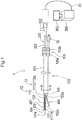
- Fig. 1 is a schematic diagram illustrating an overall configuration of a recanalization catheter system 1.
- Fig. 2 is a schematic diagram illustrating a distal end portion of a catheter 100.
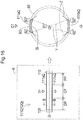
- Fig. 3 is a schematic sectional view of the catheter 100 taken along line A-A in Fig. 1 .
- the recanalization catheter system 1 is used e.g. when treating CTO (chronic total occlusion) with an antegrade approach.
- the recanalization catheter system 1 includes the catheter 100, an imaging sensor 200, an imaging console 300, and a penetration guide wire 400.
- Fig. 1 is a schematic side view of the catheter 100.
- Fig. 1 includes a part where each component is illustrated in a relative ratio of a size different from the actual size. Also, Fig. 1 includes a part where a part of each component is exaggeratedly illustrated. Additionally, in Fig. 1 , the left side is referred to as “distal end side" of each component, and the right side is referred to as proximal end side" of each component. Additionally, in each component, an end portion positioned on the distal end side is referred to as “distal end”, and an end portion positioned on the proximal end side is referred to as "proximal end”.
- distal end portion parts positioned on the distal end and in the vicinity of the distal end are referred to as distal end portion
- proximal end portion parts positioned on the proximal end and in the vicinity of the proximal end are referred to as proximal end portion.
- the catheter 100 includes a hollow outer shaft 101, a hollow first inner shaft 102, a hollow second inner shaft 103, and a hollow distal tip 104 continuous to the first inner shaft 102.
- the outer shaft 101, the first inner shaft 102, and the second inner shaft 103 have a long shape, and have substantially circular cross sections.
- the distal tip 104 has a tapered shape whose outer diameter gradually decreases toward the distal end, and has a substantially circular cross section.
- a blade 108 (see Fig. 3 ) as a reinforcing member formed by braiding a wire is embedded inside the outer peripheral face of the outer shaft 101.
- the wire constituting the blade 108 may be made of a metal material, e.g. a stainless steel such as SUS304, a nickel-titanium alloy, an alloy including gold, platinum, or tungsten that are X-ray impermeable material, or the like.
- the wire constituting the blade 108 may be made of a known metal material other than the aforementioned materials.
- a hollow coil body (not illustrated) formed by winding a wire can be embedded instead of the blade 108.
- the wire constituting the hollow coil body may be made of a metal material, e.g. a stainless steel such as SUS304, a nickel-titanium alloy, an alloy including gold, platinum, or tungsten that are X-ray impermeable material, and the like.
- the wire constituting the hollow coil body may be made of a known metal material other than the aforementioned materials.
- the first inner shaft 102 and the second inner shaft 103 are inserted into an outer lumen 113 of the outer shaft 101.
- a hollow first shaft 117a and a hollow second wire shaft 117b are inserted into the outer lumen 113.
- the first inner shaft 102, the second inner shaft 103, the first wire shaft 117a, and the second wire shaft 117b extend substantially parallel to each other along a longitudinal direction of the outer shaft 101.
- the inside of the outer lumen 113 of the outer shaft 101 is sealed by a sealing member 114.
- the sealing member 114 is disposed between an inner peripheral face of the outer shaft 101 and outer peripheral faces of the first inner shaft 102, the second inner shaft 103, the first wire shaft 117a, and the second wire shaft 117b.
- An imaging sensor 200 is inserted into a first inner lumen 115 of the first inner shaft 102 (not illustrated in Fig. 3 ).
- the first inner lumen 115 is also simply referred to as “first lumen 115".
- the penetration guide wire 400 and a normal delivery guide wire (delivery guide wire 70 described below) are inserted into a second inner lumen 116 of the second inner shaft 103 (not illustrated in Fig. 3 ).
- the second inner lumen 116 is also simply referred to as "second lumen 116".
- first inner shaft 102 forming the first lumen 115 and the second inner shaft 103 forming the second lumen 116 extend substantially parallel to each other, the first lumen 115 and the second lumen 116 are juxtaposed with each other (see Fig. 3 ).
- a first wire 112a and a second wire 112b described below are inserted into a first wire lumen 118a of the first wire shaft 117a and a second wire lumen 118b of the second wire shaft 117b respectively.
- the first wire 112a and the second wire 112b are connected to a first wire piece 111c and a second wire piece 111d respectively described below
- the first wire 112a and the second wire 112b are inserted into the first wire lumen 118a and the second wire lumen 118b respectively.
- the first wire piece 111c and the second wire piece 111d, and the first wire 112a and the second wire 112b functionally act as an "actuation portion 13" for expanding and contracting a suspension portion 111 as an expansion/contraction portion 12.
- a regulator 105 for opening/closing the suspension portion 111, and advancing/retracting the imaging sensor 200 in the first lumen 115 described below is attached to the proximal end of the outer shaft 101.
- the regulator 105 includes a first dial 105a and a second dial 105b that can be individually operated.
- the first dial 105a is used for opening and closing the suspension portion 111
- the second dial 105b is used for advancing and retracting the imaging sensor 200. Details will be described below.
- the first inner shaft 102 and the second inner shaft 103 protrudes from the distal end of the outer shaft 101.
- Apart of the second inner shaft 103 protruding from the distal end of the outer shaft 101 is configured to be shorter than a part of the first inner shaft 102 protruding from the distal end of the outer shaft 101. That means, a length of the second lumen 116 in the second inner shaft 103 in the longitudinal direction is shorter than a length of the first lumen 115 in the first inner shaft 102 in the longitudinal direction.
- the distal end of the second inner shaft 103 slopes toward the first inner shaft 102.
- An opening 103a communicating with the second lumen 116 of the second inner shaft 103 is formed on the distal end of the second inner shaft 103.
- the opening 103a corresponds to the "second opening” that communicates between the distal end portion of the second lumen 116 and the outside.
- an opening 102a communicating with the first lumen 115 of the first inner shaft 102 is formed between the distal end of the outer shaft 101 and the distal end of the first inner shaft 102.
- the opening 102a corresponds to the "first opening” that communicates between the distal end portion of the first lumen 115 and the outside.
- the distal tip 104 is joined to the distal end of the first inner shaft 102.
- An opening 104a is formed on the distal end of the distal tip 104, and the opening 104a communicates with a lumen (not illustrated) inside the distal tip 104 and the first lumen 115 of the first inner shaft 102.
- the delivery guide wire 70 (see Fig. 5A ) is inserted into the lumen inside the distal tip 104, the first lumen 115 of the first inner shaft 102, and the second lumen 116 of the second inner shaft 103.
- the proximal end of the delivery guide wire 70 enters the inside of the catheter 100 (lumen inside the distal tip 104, and the first lumen 115) from the opening 104a, then once goes out of the catheter 100 from the opening 102a, again enters the second lumen 116 of the second inner shaft 103 from the opening 103a, passes through the second lumen 116, and goes out of the catheter 100 from the proximal end of the second inner shaft 103.
- a third opening that penetrates the second inner shaft 103 and communicates with the second lumen 116 can be formed on the outer peripheral face of the outer shaft 101.
- the proximal end of the delivery guide wire 70 can be configured to go out of the catheter 100 from the third opening.
- another opening may be formed instead of the opening 102a on the outer peripheral face of the first inner shaft 102.
- another opening may be formed in a radial direction of the first inner shaft 102, at a position opposite to the opening 102a i.e. on the opposite side of the second inner shaft 103.
- the proximal end of the delivery guide wire 70 may enter the opening 104a, pass through the lumen inside the distal tip 104 and the first lumen 115 of the first inner shaft 102, and go out of the other opening.
- the outer shaft 101, the first wire shaft 117a (see Fig. 3 ), the second wire shaft 117b (see Fig. 3 ), the sealing member 114 (see Fig. 3 ), the first inner shaft 102, the second inner shaft 103, and the distal tip 104 may be made of an insulating resin, e.g.
- an polyolefin such as polyethylene, polypropylene, and ethylene-propylene copolymer, a polyester such as polyethylene terephthalate, a thermoplastic resin such as polyvinyl chloride, ethylene-vinyl acetate copolymer, crosslinkable ethylene-vinyl acetate copolymer, and polyurethane, a polyamide elastomer, a polyolefin elastomer, a polyurethane elastomer, a silicone rubber, a latex rubber, or the like.
- a polyolefin such as polyethylene, polypropylene, and ethylene-propylene copolymer
- a polyester such as polyethylene terephthalate
- a thermoplastic resin such as polyvinyl chloride, ethylene-vinyl acetate copolymer, crosslinkable ethylene-vinyl acetate copolymer, and polyurethane
- a polyamide elastomer such as polyviny
- the outer shaft 101, the first wire shaft 117a, the second wire shaft 117b, the sealing member 114, the first inner shaft 102, the second inner shaft 103, and the distal tip 104 may be made of a known material other than the aforementioned materials.
- a transducer 201 and a driving cable 202 of the imaging sensor 200 described below are disposed.
- the transducer 201 transmits an ultrasonic wave to a living tissue through the first inner shaft 102 and receives a reflected sound of the ultrasonic wave.
- the imaging console 300 acquires an image of the living tissue based on difference between the sounds transmitted and received by the transducer 201.
- a part positioned from the distal end of the first inner shaft 102 to the distal end of the outer shaft 101 is preferably made of a resin having a smaller difference in an acoustic impedance from the living tissue compared to the part of the first inner shaft 102 positioned inside the outer shaft 101, e.g. polyethylene.
- the part from the distal end of the first inner shaft 102 to the distal end of the outer shaft 101 may be formed such that a thickness of an outer peripheral wall of the part is smaller than a thickness of an outer peripheral wall of the part of the first inner shaft 102 positioned inside the outer shaft 101.
- the distal tip 104 is disposed on the distal end of the catheter 100, and is preferably made of a resin more flexible than the outer shaft 101, the first inner shaft 102, and the second inner shaft 103, e.g. a polyurethane elastomer for avoiding injury of the living tissue in the body cavity.
- the distal tip 104 can be joined to the first inner shaft 102 by any method, and e.g. joining with an insulating adhesive such as an epoxy adhesive can be adopted.
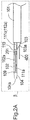
- Fig. 2A is a schematic side view of the distal end portion of the catheter 100
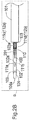
- Fig 2B and Fig. 2C are schematic bottom views of the distal end portion of the catheter 100.
- the "expansion/contraction portion 12" composed of a fixed portion 109, a sliding portion 110, and the suspension portion 111 is attached to the outer peripheral face of the first inner shaft 102 exposed from the outer shaft 101.
- Fig. 2B illustrates a state that the suspension portion 111 is closed (contracted expansion/contraction portion 12)
- Fig. 2C illustrates a state that the suspension portion 111 opens (expanded expansion/contraction portion 12).
- the fixed portion 109 is ring-shaped, and joined to the distal end of the first inner shaft 102 so as to be fixed to the first inner shaft 102.
- the fixed portion 109 may be joined to the proximal end of the distal tip 104, or may be joined to both the distal end of the first inner shaft 102 and the proximal end of the distal tip 104.
- the joining between the fixed portion 109 and the distal end of the first inner shaft 102, the joining between the fixed portion 109 and the proximal end of the distal tip 104, or the joining between the fixed portion 109 and both the distal end of the first inner shaft 102 and the proximal end of the distal tip 104 can be achieved by any method.
- the fixed portion 109 may be disposed closer to the proximal end side than the distal end side of the first inner shaft 102.
- the sliding portion 110 is ring-shaped, disposed apart from the fixed portion 109 on the proximal end side of the fixed portion 109, and slidably mounted along the longitudinal direction of the first inner shaft 102 on the outer peripheral face of the first inner shaft 102.
- the suspension portion 111 is disposed between the fixed portion 109 and the sliding portion 110.
- the suspension portion 111 according to the first embodiment includes a first suspension portion 111a and a second suspension portion 111b (the second suspension portion 111b is not illustrated in Fig. 1 ).
- the distal end and the rear end of the first suspension portion 111a are joined to the fixed portion 109 and the sliding portion 110 respectively.
- the distal end and the rear end of the second suspension portion 111b are also joined to the fixed portion 109 and the sliding portion 110 respectively.
- Each of the first suspension portion 111a and the second suspension portion 111b connects the fixed portion 109 with the sliding portion 110, and extends in the longitudinal direction of the first inner shaft 102.
- the first suspension portion 111a and the second suspension portion 111b are arranged so as to be opposite to each other in the radial direction of the first inner shaft 102.
- the first suspension portion 111a and the second suspension portion 111b are disposed so as to be present on a virtual plane ⁇ , as illustrated in Fig. 2B and Fig. 2C .
- the first inner shaft 102 and the second inner shaft 103 are disposed such that the longitudinal axis of the first inner shaft 102 and the longitudinal axis of the second inner shaft 103 are present in a virtual plane ⁇ .
- the first suspension portion 111a and the second suspension portion 111b are preferably arranged such that the virtual plane ⁇ and the virtual plane ⁇ are substantially perpendicular to each other.
- the virtual plane ⁇ including the first suspension portion 111a and the second suspension portion 111b is also referred to as a "first virtual plane”.
- the opening 102a as the first opening is perpendicular to the virtual plane ⁇ including the first suspension portion 111a and the second suspension portion 111b, and is formed at a position where a virtual plane X positioned between the fixed portion 109 and the sliding portion 110 intersects with the outer peripheral face of the first inner shaft 102.
- an image of the delivery guide wire 70 acquired by the imaging sensor 200 can functionally act as a land mark.
- the opening 102a is disposed on the same side as of the second inner shaft 103 and the opening 103a and on the extended line of the second inner shaft 103 and the opening 103a.
- the proximal end of the delivery guide wire 70 protruding from the opening 102a can be easily inserted into the second lumen 116 from the opening 103a.
- the virtual plane X perpendicular to the virtual plane ⁇ and positioned between the fixed portion 109 and the sliding portion 110 is also referred to as "second virtual plane".
- the first suspension portion 111a and the second suspension portion 111b when the first suspension portion 111a and the second suspension portion 111b are closed, the first suspension portion 111a and the second suspension portion 111b extend between the fixed portion 109 and the sliding portion 110, in the longitudinal direction of the first inner shaft 102, substantially parallel to the first inner shaft 102.
- the sliding portion 110 is disposed as close as possible to the proximal end side i.e. the opening 103a.
- the proximal end of the sliding portion 110 may be disposed at the distal end of the opening 103a.
- first suspension portion 111a and the second suspension portion 111b can be increased, and therefore, for example, deviation of the catheter 100 in a false cavity can be further reduced.
- first suspension portion 111a and the second suspension portion 111b expand outward in the radial direction of the first inner shaft 102, and open. In both states of the opened and closed suspension portion 111, the sliding portion 110 is disposed on the proximal end side of the opening 102a.
- Cross-sectional shapes of the first suspension portion 111a and the second suspension portion 111b can be made rectangular. Thereby, the suspension portions can be easily expanded outward in the radial direction e.g. compared to the case that the cross-sectional shape is square or circle.
- the suspension portion 111, the fixed portion 109, and the sliding portion 110 are made of a metal material or a resin material.
- a metal material they may be made of e.g. a stainless steel such as SUS304, a nickel-titanium alloy, an alloy including gold, platinum, or tungsten that are X-ray impermeable material, and the like.
- a resin material they may be made of e.g.
- a polyolefin such as polyethylene, polypropylene, and ethylene-propylene copolymer, a polyester such as polyethylene terephthalate, a thermoplastic resin such as polyvinyl chloride, ethylene-vinyl acetate copolymer, crosslinkable ethylene-vinyl acetate copolymer, and polyurethane, a polyamide elastomer, a polyolefin elastomer, a polyurethane elastomer, a silicone rubber, a latex rubber, or the like.
- the suspension portion 111, the fixed portion 109, and the sliding portion 110 may be made of a known metal material or resin material other than the aforementioned materials.
- the suspension portion 111 is made of a shape-memory nickel-titanium alloy, preferably a state that the suspension portion 111 closes is previously memorized to the nickel-titanium alloy. Thereby, the suspension portion 111 can be relatively easily transitioned from the open state to the closed state.
- the suspension portion 111 can be joined to the fixed portion 109 and the sliding portion 110 by any method.
- the suspension portion 111, the fixed portion 109, and the sliding portion 110 are made of a resin, or when the suspension portion 111 is made of a metal material and the fixed portion 109 and the sliding portion 110 are made of a resin material, or when the suspension portion 111 is made of a resin material and the fixed portion 109 and the sliding portion 110 are made of a metal material, joining with an adhesive e.g. an epoxy adhesive can be adopted.
- the suspension portion 111, the fixed portion 109, and the sliding portion 110 are made of a metal material, it is possible to adopt joining by laser welding, or brazing using a metal solder such as silver solder, gold solder, zinc, Sn-Ag alloy, and Au-Sn alloy.
- a metal solder such as silver solder, gold solder, zinc, Sn-Ag alloy, and Au-Sn alloy.
- the sliding portion 110 is joined to the first wire 112a and the second wire 112b (only the first wire 112a is illustrated in Fig. 2A ).
- the first wire piece 111c described below is disposed on the proximal end of the sliding portion 110 (see Fig. 2E ).
- the first wire 112a is arranged along the longitudinal direction of the first inner shaft 102 so as to overlap with this first wire piece 111c (see Fig. 2E and Fig. 3 ) and joined to the first wire piece 111c.
- the second wire piece 111d described below is disposed on the proximal end of the sliding portion 110 (see Fig. 2E ).
- the second wire 112b is disposed along the longitudinal direction of the first inner shaft 102 so as to overlap with this second wire piece 111d (see Fig. 2E and Fig. 3 ) and joined to the second wire piece 111d.
- Each of the first wire piece 111c and the second wire piece 111d passes through the first wire lumen 118a and the second wire lumen 1118b described below and extends to the way to the outer shaft 101.
- the first wire 112a and the second wire 112b extend from the proximal end of the sliding portion 110 toward the proximal end of the first inner shaft 102 in the longitudinal direction of the first inner shaft 102 along the outer peripheral face of the middle part of the first inner shaft 102.
- the first wire 112a is configured to be longer than the first wire piece 111c, but they may have the same length.
- the second wire 112b is configured to be longer than the second wire piece 111d, but they may have the same length.
- the first wire piece 111c and the second wire piece 111d are made of a thin plate member whose cross section is substantially rectangular or arcuate.
- the first wire 112a and the second wire 112b are made of a round wire having a substantially circular cross section.
- the first wire 112a is formed such that an outer diameter of a part overlapping with the first wire piece 111c is smaller than an outer diameter of a part not overlapping with the first wire piece 111c.
- the second wire 112b is formed such that an outer diameter of a part overlapping with the second wire piece 111d is smaller than an outer diameter of a part not overlapping with the second wire piece 111d.
- the first wire 112a and the first wire piece 111c are arranged substantially parallel to the closed first suspension portion 111a.
- the first wire 112a and the first wire piece 111c are deviated toward the second inner shaft 103 relative to the first suspension portion 111a in a circumferential direction of the sliding portion 110 (in other words, in a circumferential direction of the first inner shaft 102).
- the second wire 112b and the second wire piece 111d are arranged substantially parallel to the closed second suspension portion 111b (not illustrated in Fig. 2A ).
- the second wire 112b and the second wire piece 111d are arranged on the second inner shaft 103 side relative to the second suspension portion 111b in the circumferential direction of the sliding portion 110 (in other words, in the circumferential direction of the first inner shaft 102) (not illustrated in Fig. 2A ).
- each of the first wire 112a and the second wire 112b is connected to the first dial 105a of the regulator 105 (see Fig. 1 ) through the first wire lumen 118a or the second wire lumen 118b respectively of the outer shaft 101.
- the sliding portion 110 is moved toward the distal end of the first inner shaft 102 on the outer peripheral face of the first inner shaft 102, and thereby the suspension portion 111 can be expanded.
- a degree of expansion of the suspension portion 111 can be regulated while observing an image of a living tissue based on ultrasonic signals from the imaging sensor 200 described below by an imaging console 300 described below, so that vascular injury can be minimized.
- the sliding portion 110 is moved toward the proximal end of the first inner shaft 102 through the first wire 112a and the second wire 112b on the outer peripheral face of the first inner shaft 102 in a state that the suspension portion 111 is expanded, so that the suspension portion 111 can be returned to the closed state.
- the first wire 112a and the second wire 112b are made of a metal material or a resin material.
- a metal material they may be made of e.g. a chrome-molybdenum steel, a nickel-chrome-molybdenum steel, a stainless steel such as SUS304, a nickel-titanium alloy, or the like.
- a resin material they may be made of e.g. a super engineering plastic such as polyetheretherketone, polyetherimide, polyamideimide, polysulfone, polyimide, and polyethersulfone.
- the first wire 112a and the second wire 112b may be made of a known metal material or resin material other than these materials.
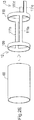
- Fig. 2D is a diagram for explaining a method for integrally forming the expansion/contraction portion 12.
- the suspension portion 111, the fixed portion 109, and the sliding portion 110 as the expansion/contraction portion 12 may be formed as separate bodies, they can be integrally formed.
- the fixed portion 109, the sliding portion 110, the first suspension portion 111a, and the second suspension portion 111b are formed by cutting out a side wall of a cylindrical hollow pipe 60 made of a resin material or a metal material, as illustrated in Fig. 2D .
- the first wire 112a and the second wire 112b are directly joined to the sliding portion 110.
- first wire 112a and the second wire 112b can be joined with the sliding portion 110 by any method.
- first wire 112a, the second wire 112b, and the sliding portion 110 are made of a resin, or when the first wire 112a and the second wire 112b are made of a metal material and the sliding portion 110 is made of a resin material, or when the first wire 112a and the second wire 112b are made of a resin material and the sliding portion 110 is made of a metal material, joining e.g. with an adhesive such as an epoxy adhesive can be adopted.
- first wire 112a, the second wire 112b, and the sliding portion 110 are made of a metal material, joining by laser welding, or brazing using a metal solder such as silver solder, gold solder, zinc, Sn-Ag alloy, and Au-Sn alloy can be adopted.
- a metal solder such as silver solder, gold solder, zinc, Sn-Ag alloy, and Au-Sn alloy
- Fig. 2E is a diagram for illustrating a method for integrally forming the expansion/contraction portion 12 and a part of the actuation portion 13.
- the side wall of the cylindrical hollow pipe 60 made of a resin material or a metal material is cut out to form the fixed portion 109, the sliding portion 110, the first suspension portion 111a, and the second suspension portion 111b as the expansion/contraction portion 12, as well as the first wire piece 111c and the second wire piece 111d as the actuation portion 13.
- the first wire piece 111c is substantially parallel to the closed first suspension portion 111a, and deviated toward the second inner shaft 103 from the first suspension portion 111a in the circumferential direction of the sliding portion 110 (see Fig. 2A ).
- the second wire piece 111d is substantially parallel to the closed second suspension portion 111b, and deviated toward the second inner shaft 103 from the second suspension portion 111b in the circumferential direction of the sliding portion 110.
- first wire 112a and the first wire piece 111c can be joined to each other such that they overlap with each other in the longitudinal direction of the first inner shaft 102.
- second wire 112b and the second wire piece 111d can be joined to each other such that they overlap with each other in the longitudinal direction of the first inner shaft 102 (see Fig. 3 ).
- Fig. 2E the configuration illustrated in Fig. 2E is described in the catheter 100 in Fig. 1 to Fig. 2C , Fig. 3 , and Fig. 5A to Fig. 5D .
- Fig. 2F is a diagram for illustrating another method for integrally forming the expansion/contraction portion 12 and a part of the actuation portion 13.
- the side wall of the cylindrical hollow pipe 60 made of a resin material or a metal material is cut out to form the fixed portion 109, the sliding portion 110, the first suspension portion 111a, and the second suspension portion 111b as the expansion/contraction portion 12, as well as a first wire piece 120 and a second wire piece 121 as the actuation portion 13.
- the first wire piece 120 is composed of a first curved portion 120a, and a first straight portion 120b continuous with the first curved portion 120a.
- the first curved portion 120a is curved toward the second inner shaft 103 (see Fig.
- the second wire piece 121 is composed of a second curved portion 121a, and a second straight portion 121b continuous with the second curved portion 121a.
- the second curved portion 121a is curved toward the second inner shaft 103 (see Fig. 2A ), and the second straight portion 121b extends substantially parallel to the closed second suspension portion 111b.
- the first curved portion 120a and the second curved portion 121a may be formed in a straight shape.
- first wire 112a and the first straight portion 120b of the first wire piece 120 are joined to each other such that they overlap with each other in the longitudinal direction of the first inner shaft 102.
- second wire 112b and the second straight portion 121b of the second wire piece 121 are joined to each other such that they overlap with each other in the longitudinal direction of the first inner shaft 102.
- Joining between the first wire 112a and the first straight portion 120b of the first wire piece 111c or the first wire piece 120 can be achieved by any method.
- first wire 112a, the first wire piece 111c, and the first wire piece 120 are made of a resin, or when the first wire 112a is made of a metal material and the first wire piece 111c and the first wire piece 120 are made of a resin material, or when the first wire 112a is made of a resin material and the first wire piece 111c and the first wire piece 120 are made of a metal material, joining e.g. with an adhesive such as an epoxy adhesive can be adopted.
- first wire 112a, the first wire piece 111c, and the first wire piece 120 are made of a metal material, joining by laser welding, or brazing using a metal solder such as silver solder, gold solder, zinc, Sn-Ag alloy, and Au-Sn alloy can be adopted.
- a metal solder such as silver solder, gold solder, zinc, Sn-Ag alloy, and Au-Sn alloy. The same applies to joining between the second wire 112b and the second straight portion 121b of the second wire piece 111d or the second wire piece 121.
- the first wire 112a joined to the first wire piece 111c (see Fig. 2E ) formed by cutting out the side wall of the hollow pipe 60 is inserted into the first wire lumen 118a.
- the second wire 112b joined to the second wire piece 111d (see Fig. 2E ) formed by cutting out the side wall of the hollow pipe 60 is inserted into the second wire lumen 118b.
- the first wire piece 111c is replaced by the first straight portion 120b of the first wire piece 120
- the second wire piece 111d is replaced by the second straight portion 121b of the second wire piece 121, in the sectional view in Fig. 3 .
- Fig. 1 , Fig. 2A , Fig. 2B , and Fig. 2C illustrate the configuration that the suspension portion 111 is expanded by pushing the proximal end of the suspension portion 111 toward the distal end while fixing the distal end of the suspension portion 111
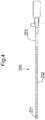
- Fig. 4 is a schematic diagram illustrating the imaging sensor 200.
- the imaging sensor 200 is a long medical device, and is composed of the transducer 201 that transmits and receives ultrasonic waves, the hollow driving cable 202, and a connector 203.
- An electric wire (not illustrated) is connected to the transducer 201, and the electric wire is connected to a cable 50 through a lumen inside the hollow driving cable 202 and a lumen inside the connector 203 (see Fig. 1 ).
- the cable 50 is connected to the imaging console 300.
- the transducer 201 disposed on the distal end transmits ultrasonic waves in the radial direction while rotating around the longitudinal axis of the transducer in a body cavity, and receives ultrasonic waves reflected from a living tissue.
- the transducer 201 transmits the received ultrasonic waves to the imaging console 300 through the aforementioned electric wire and the cable 50.
- the imaging sensor 200 is used while inserted into the first lumen 115 of the first inner shaft 102.
- the imaging sensor 200 is connected to the second dial 105b of the regulator 105 between the distal end and the proximal end of the imaging sensor 200.
- the transducer 201 arranged on the distal end of the imaging sensor 200 can be moved forward and backward along the longitudinal direction of the first inner shaft 102.
- the imaging console 300 illustrated in Fig. 1 controls rotation of the transducer 201, and transmission and reception of the ultrasonic waves by the transducer 201, and also converts ultrasonic signals received from the transducer 201 into image signals to display an image on a display 302.
- the penetration guide wire 400 (see Fig. 1 , and Fig. 2A to Fig. 2C ) is a long medical device having a pointed portion on the distal end.
- the pointed portion has an arrowhead shape or a cuneus shape that are tapered from the proximal end side toward the distal end side.
- the penetration guide wire 400 can penetrate a living tissue by the pointed portion formed on the distal end.
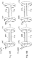
- Fig. 5 is a diagram illustrating a usage example of the recanalization catheter system 1.
- Fig. 5A illustrates a state that the delivery guide wire 70 is inserted into a coronary artery 80.
- Fig. 5B illustrates a state that the delivery guide wire 70 is inserted into the catheter 100, and the catheter 100 is inserted into the coronary artery 80 along the delivery guide wire 70.
- Fig. 5C illustrates a state that the suspension portion 111 of the expansion/contraction portion 12 is expanded.
- Fig. 5D illustrates a state that the penetration guide wire 400 penetrates a living tissue.
- FIG. 5A to D illustrates the coronary artery 80 as an example of a living body lumen, a CTO 81 caused in the coronary artery 80, a false cavity 82 formed in or under an intima of the coronary artery 80 (all dissected cavities other than true cavities formed by the delivery guide wire 70), a true cavity 84, and a fibrous cap or plaque 83 (hereinafter simply referred to as "fibrous cap 83") present between the false cavity 82 and the true cavity 84.
- the fibrous cap 83 is formed in a fiber form on a surface of the CTO lesion in some cases.
- Fig. 5A illustrates a state that the delivery guide wire 70 operated by an operator deviates into the intima of the coronary artery 80 or forms the false cavity 82 under the intima.
- the operator inserts the proximal end of the delivery guide wire 70 into the second lumen 116 of the second inner shaft 103 from the opening 104a of the distal tip 104 of the catheter 100, through the lumen inside the distal tip 104 and the first lumen 115 of the first inner shaft 102 (see Fig. 3 ), and through the opening 102a of the first inner shaft 102. Then, the catheter 100 is transported to the false cavity 82 along the delivery guide wire 70, and insides of the CTO lesion and the false cavity 82 are observed with the imaging sensor 200.
- the operator transports the catheter 100 in a state that the transducer 201 of the imaging sensor 200 is positioned immediately near the proximal end of the opening 102a in the first lumen 115 of the first inner shaft 102. This is because the observation site of the imaging sensor 200 is moved by moving the catheter 100. While transporting the catheter 100, the operator confirms an image of the coronary artery 80 from the transducer 201 on the display 302, so that the catheter 100 is disposed at an optimum position for penetration into the true cavity with the penetration guide wire 400.
- the operator operates the first dial 105a of the regulator 105, so that the sliding portion 110 is moved toward the distal end through the first wire 112a and the second wires 112b to extend the suspension portion 111 (the expanded suspension portion 111 is not illustrated in Fig. 5B ). Expansion of the suspension portion 111 pushes the living tissue in the false cavity 82, and thereby the catheter 100 is fixed. The operator expands the suspension portion 111 while confirming an expanded position and an expansion degree of the suspension portion 111 by the imaging sensor 200, so that the catheter 100 is fixed at an optimum position for fixing the catheter 100 without excessive expansion of the false cavity.
- fixation of the catheter 100 is confirmed with the imaging sensor 200, and the delivery guide wire 70 is removed.
- the second dial 105b of the regulator 105 is operated, an optimum site for penetration into the true cavity is observed and determined by advancing and retracting the imaging sensor 200 along the longitudinal direction of the first inner shaft 102.
- the operator inserts the penetration guide wire 400 into the second lumen 116 of the second inner shaft 103 while confirming the image of the coronary artery 80 from the transducer 201 with the display 302, so that the penetration guide wire 400 protrudes from the opening 103a on the distal end.
- the pointed portion of the penetration guide wire 400 is introduced to the aforementioned optimum site for penetration.
- the living tissue is penetrated using the pointed portion of the penetration guide wire 400, and the distal end of the penetration guide wire 400 is made to reach the true cavity 84.
- the method illustrated in Fig. 5A to Fig. 5D makes it possible to canalize the CTO 81 with the recanalization catheter system 1.
- the recanalization catheter system 1 may be used for not only the approach from the false cavity 82 to the true cavity 84 explained in Fig. 5 but also the approach of penetrating the CTO from the true cavity 84 on the proximal side to the true cavity 84 on the distal side.
- the outer shaft 101, the first inner shaft 102, the second inner shaft 103, the first and second wire shafts 117a and 117b, and the sealing member 114 correspond to the "shaft”.
- the distal end face of the second inner shaft 103 exposed from the distal end of the outer shaft 101 corresponds to the "end face” having the second opening (opening 103a).
- the imaging sensor 200 corresponds to the "sensor” that acquires information on the living tissue
- the penetration guide wire 400 corresponds to the "guide wire that penetrates the living tissue”.
- the suspension portion 111 expands in the radial direction of the first inner shaft 102 (shaft), so that the catheter 100 can be fixed inside the false cavity 82 (under intima) (see Fig. 5C ).
- the suspension portion 111 connects the fixed portion 109 fixed to the first inner shaft 102 with the sliding portion 110 slidable on the outer peripheral face of the first inner shaft 102 and has a shape extending in the longitudinal direction of the first inner shaft 102, and therefore the suspension portion 111 has a different configuration from the conventional configuration (expandable and contractable tubular balloon).
- the recanalization catheter system 1 according to the first embodiment makes it possible to provide the catheter 100 that can be fixed inside the false cavity by a method different from the conventional method.
- the suspension portion 111 includes the two suspension portions 111 (first suspension portion 111a and second suspension portion 111b), a resistance force against the operation of moving the catheter 100 in the longitudinal direction and the operation of turning the catheter 100 in the circumferential direction can be further enhanced, and the fixation force for the catheter 100 in the false cavity can be further enhanced.
- the first suspension portion 111a and the second suspension portion 111b are arranged so as to be opposite to each other as illustrated in Fig. 2B , and individually expand in the radial direction of the shaft as illustrated in Fig. 2C .
- the shape of the expanded suspension portion 111 expansion/contraction portion 12
- unnecessary expansion of the false cavity 82 can be reduced compared to the expansion of the conventional expandable and contractable tubular balloon.
- the second inner shaft 103 as the shaft further has the second lumen 116 juxtaposed with the first lumen 115 (see Fig. 3 ).
- a plurality of medical devices can be simultaneously held in one catheter 100, e.g. in such a way that the imaging sensor 200 for acquiring information on the living tissue is inserted into the first lumen 115 and the penetration guide wire 400 for penetrating the living tissue is inserted into the second lumen 116.
- the second lumen 116 is shorter than the first lumen 115 (see Fig. 1 ).
- the imaging sensor 200 is inserted into the longer first lumen 115, and the transducer 201 of the imaging sensor 200 (site that transmits and receives ultrasonic waves to/from the living tissue) is disposed on the distal end portion of the first lumen 115, so that the distal end portion of the medical device (e.g. delivery guide wire 70, penetration guide wire 400, or the like) inserted into the shorter second lumen 116 can be observed with the imaging sensor 200.
- the medical device e.g. delivery guide wire 70, penetration guide wire 400, or the like
- the catheter 100 makes it possible to achieve a procedure for the imaging sensor 200 under a guide without requiring a skill for separately manipulating a plurality of devices in a blood vessel, and a skill for three-dimensionally reconstructing the imaging sensor 200 image and X-ray images, that have been conventionally required for the procedures of the imaging sensor 200 under the guide (e.g. IVUS Guide).
- the catheter 100 according to the first embodiment makes it possible to achieve the procedure only by confirming the image of the imaging sensor 200, a number of acquirements of the X-ray images can also be decreased, and it can be expected that an exposure dose to an operator and a patient associated with X-ray photography is decreased, and an amount of a contrast medium used for the X-ray photography is decreased.
- the second inner shaft 103 as a shaft has an end face where the opening 103a (second opening) communicating between the distal end portion of the second lumen 116 and the outside (see Fig. 2B ).
- the proximal end portion of the delivery guide wire 70 is taken out from the opening 102a (first opening), and then the proximal end portion of the delivery guide wire 70 is inserted into the second lumen 116 from the opening 103a, so that the delivery guide wire 70 can be fixed to the distal end portion of the first inner shaft 102 as the shaft.
- the delivery guide wire 70 can be oriented constantly in a certain direction relative to the catheter 100 on the image acquired by the imaging sensor 200.
- the operator can control the catheter 100 such that the position of the target site relative to the catheter 100, where the penetration guide wire 400 penetrates the living tissue, is optimized (optimum angle), by advancing/retracting and turning the catheter 100 relative to the delivery guide wire 70 while confirming the image from the imaging sensor 200.
- the distal end portion of the first lumen 115 for the imaging sensor 200 is used.
- the first lumen 115 is shared by the delivery guide wire 70 and imaging sensor 200.
- the catheter 100 can be reduced in diameter, and can be easily inserted into the living body lumen (e.g. into the coronary artery 80, the CTO 81, or the like), compared to a case of disposing a separate lumen for fixing the delivery guide wire 70.
- the living body lumen e.g. into the coronary artery 80, the CTO 81, or the like
- the distal end portion of the penetration guide wire 400 when the penetration guide wire 400 penetrates the living tissue, the distal end portion of the penetration guide wire 400 is protruded outward from the opening 103a (second opening) while the penetration guide wire 400 is inserted into the second lumen 116, so that the distal end portion of the penetration guide wire 400 can confront the target site while obtaining a backup force from the first inner shaft 102.
- the expansion/contraction portion 12 (fixed portion 109, sliding portion 110, suspension portion 111) is disposed in the first inner shaft 102 forming the first lumen 115.
- the suspension portion 111 of the expansion/contraction portion 12 is made of a material having a difference in an acoustic impedance from the living tissue, a state of the expanded suspension portion 111 can be observed by the imaging sensor 200 inserted into the first lumen 115, and therefore the suspension portion 111 can be safely expanded while suppressing injury in the living body lumen associated with overexpansion of the suspension portion 111.
- the expansion/contraction portion 12 is made of a radiopaque material, the expansion/contraction portion 12 can be made to functionally act as an orientation marker for x-ray-fluoroscopically confirming a posture and an orientation of the catheter 100 by imaging the expansion/contraction portion 12 on an X-ray image obtained by X-ray photography.
- an image acquisition site can be moved by moving the imaging sensor 200 in the first lumen 115.
- a positional relationship between the distal end portion of the penetration guide wire 400 and the target site for penetration can be observed by conforming the image acquisition site to the distal end portion of the penetration guide wire 400.
- a number of acquisitions of X-ray images can be minimized.
- the imaging sensor 200 that is inserted into the first lumen 115 is larger in diameter than the medical device (e.g. delivery guide wire 70, penetration guide wire 400, or the like) that is inserted into the second lumen 116.
- the diameter of the first lumen 115 is larger than the diameter 116 of the second lumen (see Fig. 3 ).
- each diameter of the first and second lumens can be conformed to a thickness of each device inserted into each lumen, and furthermore errors during insertion of the device can be suppressed and the catheter 100 can be reduced in diameter compared to a case that the diameters of the first and second lumens are the same.
- the catheter 100 includes the blade 108 disposed inside the outer shaft 101 (in the wall portion of the shaft), a torque transmission performance of the catheter 100 can be improved.
- the blade 108 is made of a radiopaque material, a reinforcing member can be imaged on an X-ray image obtained by X-ray photography.
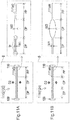
- Fig. 6 is an explanatory diagram illustrating configurations of expansion/contraction portions 12A and B according to the second embodiment.
- Fig. 6A illustrates an example of a configuration of the expansion/contraction portion 12A
- Fig. 6B illustrates an example of a configuration of the expansion/contraction portion 12B.
- a catheter 100A according to the second embodiment illustrated in Fig. 6A includes the expansion/contraction portion 12A having a configuration different from the first embodiment.
- the expansion/contraction portion 12A includes a suspension portion 111A composed of the first suspension portion 111aA and a second suspension portion 111bA.
- a catheter 100B according to the second embodiment illustrated in Fig. 6B includes the expansion/contraction portion 12B having a configuration different from the first embodiment.
- the expansion/contraction portion 12B includes a suspension portion 111B composed of the first suspension portion 111aB and a second suspension portion 111bB.
- the first suspension portions 111aA and B, and the second suspension portions 111bA and B are constitutively symmetrical with each other relative to an axis line (center) of the catheter 100A.
- configurations of the suspension portions 111A and B will be explained with reference to enlarged views of the first suspension portions 111aA and B on the right side.
- each of the suspension portion 111A and the suspension portion 111B includes a distal end portion DP positioned on the distal end side, a central portion CP, and a proximal end portion PP positioned on the proximal end side, in the longitudinal direction of the catheter 100A or B respectively.
- the central portion CP is positioned between the distal end portion DP and the proximal end portion PP.
- a rigidity of the central portion CP are relatively different from rigidities of the distal end portion DP and the proximal end portion PP. Specifically, in the example of Fig.
- the suspension portion 111A is configured such that a thickness T2 of the central portion CP in an expanding direction of the suspension portion 111A (white arrows on the left side of Fig. 6A , hereinafter also referred to as "expansion direction D1") is larger than thicknesses T1 of the distal end portion DP and the proximal end portion PP.
- expansion direction D1 a thickness of the central portion CP in an expanding direction of the suspension portion 111A
- the rigidity of the central portion CP can be made higher than the rigidities of the distal end portion DP and the proximal end portion PP.
- the suspension portion 111B is configured such that the thickness T2 of the central portion CP in the expansion direction D1 is smaller than the thicknesses T1 of the distal end portion DP and the proximal end portion PP.
- the rigidity of the central portion CP can be made lower than the rigidities of the distal end portion DP and the proximal end portion PP.
- the thicknesses T1 and T2 can be arbitrarily determined as long as they are different.
- the suspension portions 111A and B are configured such that a length L1 of the distal end portion DP and a length L1 of the proximal end portion PP are substantially the same in the longitudinal direction of the catheters 100A and B, and a length L2 of the central portion CP is longer than the length L1 of the distal end portion DP.
- the lengths L1 and L2 can be arbitrarily determined.
- Fig. 7 is an explanatory diagram illustrating a state that the expansion/contraction portion 12A according to the second embodiment expands.
- the rigidity of the central portion CP is relatively different from the rigidities of the distal end portion DP and the proximal end portion PP, as described above.
- a shape of the suspension portion 111A expanding in the expansion direction D1 can be a substantially trapezoidally expanding shape when each of a boundary between the central portion CP and the distal end portion DP and a boundary between the central portion CP and the proximal end portion PP is bent, and the central portion CP is away from the outer peripheral face of the first inner shaft 102 substantially parallel to the longitudinal direction (the right side of Fig. 7 , circle with dot and dash line).
- the suspension portion 111B according to the second embodiment explained in Fig. 6B can also have substantially trapezoidally expanding shape because the rigidity of the central portion CP is relatively different from the rigidity of the distal end portion DP and the proximal end portion PP.
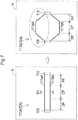
- Fig. 8 is an explanatory diagram illustrating a state of the expansion/contraction portion 12A in the false cavity 82.
- Fig. 8A illustrates a state that the expansion/contraction portion 12A according to the second embodiment explained in Fig. 6A is expanded
- Fig. 8B illustrates a state that an expansion/contraction portion 12X of a comparative example is expanded.
- Fig. 8 illustrates the cross section of the coronary artery 80 explained in Fig. 5
- an extending direction of a center O of the coronary artery 80 in Fig. 8 coincides with the longitudinal direction of the catheter 100A.
- a catheter 100X of a comparative example includes a tubular balloon 111X that is expandable and contractable as the expansion/contraction portion 12X, instead of the fixed portion 109, the sliding portion 110, and the suspension portion 111A.
- the false cavity 82 is a dissociated cavity formed by partial exfoliation of a vascular tissue e.g. a cavity between an intimal tissue layer and an adventitial tissue layer of the coronary artery 80, the false cavity 82 has a flatter cross-sectional shape compared to the true cavity 84.
- the suspension portion 111A (first suspension portion 111aA, second suspension portion 111bA) made of a plate-shaped member extending in the longitudinal direction expands in the expansion direction D1 to push a wall face (living tissue) of the false cavity 82, so that the catheter 100A is fixed.
- the catheter 100A can be fixed inside the false cavity 82 without expanding the false cavity 82, by conforming the longitudinal direction of the flat false cavity 82 to the expansion direction D1 of the suspension portion 111A in the cross-section as illustrated in Fig. 8A .
- the rigidity of the central portion CP is relatively different from the rigidities of the distal end portion DP and the proximal end portion PP positioned on both ends of the central portion CP, and therefore the shape of the suspension portion 111A expanding in the expansion direction D1 can be a substantially trapezoid (the right side of Fig. 7 , circle with dot and dash line).
- a contact area where the suspension portion 111A is in contact with the wall face (living tissue) of the false cavity 82 can be increased compared to a case without the difference in rigidity.
- a possibility to enlarge the false cavity 82 due to expansion of the suspension portion 111A can be reduced, and furthermore injury of the living body due to the suspension portion 111A when operating of turning the catheter 100A in the circumferential direction can be suppressed.
- a friction resistance with the living tissue wall face can be enhanced as the contact area increases, a resistance force against the operation of moving the catheter 100A in the longitudinal direction and the operation of turning the catheter 100A in the circumferential direction can be enhanced. In other words, a force to fix the catheter 100A can be enhanced.
- the thickness T2 of the central portion CP is made relatively different from the thicknesses T1 of the distal end portion DP and the proximal end portion PP, so that they can have different rigidities (see Fig. 6 ).
- a resistance force against the operation of turning the suspension portion 111A in the circumferential direction can be enhanced by varying the rigidity depending on the thickness (wall thickness) as described above.
- the lengths L1 of the distal end portion DP and the proximal end portion PP in the longitudinal direction are substantially the same, and the length L2 of the central portion CP is larger than the length L1 of the distal end portion DP (see Fig. 6 ).
- the contact area where the suspension portion 111A is in contact with the living tissue can be increased, and a fixation force for the catheter 100A can be further enhanced.
- the catheter 100A can be fixed in the false cavity 82 (under intima), and deviation of the catheter 100A can be suppressed.
- the suspension portion 111B according to the second embodiment explained in Fig. 6B the same effects as the aforementioned effects can be exhibited.
- the expansion direction of the balloon 111X is a direction DX radially expanding from the center ( Fig. 8B , black arrow).
- expansion of the balloon 111X presses the wall face (living tissue) of the flat false cavity 82, and therefore the false cavity 82 may be expanded.
- the balloon 111X easily turns in the circumferential direction in the false cavity 82, the resistance force against the operation of moving the catheter 100X in the longitudinal direction and the operation of turning the catheter 100X in the circumferential direction cannot be sufficiently obtained.
- Fig. 9 is an explanatory diagram illustrating configurations of expansion/contraction portions 12C and D according to the third embodiment.
- Fig. 9A illustrates an example of the configuration of the expansion/contraction portion 12C
- Fig. 9B illustrates an example of the configuration of the expansion/contraction portion 12D.
- a rigidity of a central portion CP is made different from rigidities of a distal end portion DP and a proximal end portion PP by a method different from that in the second embodiment.
- the suspension portion 111C is configured such that one notch 111n is formed on each substantially central portion of outer side faces (outer peripheral faces) of the distal end portion DP and the proximal end portion PP.
- two notches 111n are formed on both end portions of an inner side face (inner peripheral face) of the central portion CP. In such a way, the rigidity of the central portion CP can be made different from the rigidities of the distal end portion DP and the proximal end portion PP.
- one notch 111n is formed on each substantially central portion of inner side faces of the distal end portion DP and the proximal end portion PP, and two notches 111n are formed on both end portions of an outer side face of the central portion CP. Also in such a way, the rigidity of the central portion CP can be made different from the rigidities of the distal end portion DP and the proximal end portion PP.
- the rigidity of the central portion CP may be made different from the rigidities of the distal end portion DP and the proximal end portion PP by a means other than the thickness, such as a number and positions of the notches 111n formed in the suspension portions 111C and D as in the third embodiment. Also in such a way, the same effect as of the second embodiment can be exhibited. Additionally, in the suspension portions 111C and D according to the third embodiment, the suspension portions 111C and D can be bent at a position of the notch 111n, which is made brittler than other areas, and therefore it is easy to control the shapes of the expanded suspension portions 111C and D depending on the position having the notch 111n.
- Fig. 10 is an explanatory diagram illustrating configurations of the expansion/contraction portions 12E and F according to the fourth embodiment.
- Fig. 10A illustrates an example of the configuration of the expansion/contraction portion 12E
- Fig. 10B illustrates an example of the configuration of the expansion/contraction portion 12F.
- the contracted expansion portions 12E and F on the virtual plane ⁇ substantially perpendicular to the virtual plane ⁇ illustrated in Fig. 6 are illustrated, and on the right side, enlarged views of first suspension portions 111aE and F are illustrated.
- a rigidity of a central portion CP is made different from rigidities of a distal end portion DP and a proximal end portion PP by a method different from that in the second embodiment.
- the suspension portion 111E is configured such that a width W2 of the central portion CP in a direction orthogonal to the expansion direction D1 ( Fig. 6 ) of the suspension portion 111E (an arrow diagonally hatched on the left side of Fig. 10A , hereinafter referred to as "orthogonal direction D2") is larger than widths W1 of the distal end portion DP and the proximal end portion PP.
- the rigidity of the central portion CP can be made higher than the rigidities of the distal end portion DP and the proximal end portion PP.
- the suspension portion 111F is configured such that the width W2 of the central portion CP in the orthogonal direction D2 is smaller than the widths W1 of the distal end portion DP and the proximal end portion PP.
- the rigidity of the central portion CP can be made lower than the rigidities of the distal end portion DP and the proximal end portion PP.
- the widths W1 and W2 can be arbitrarily determined as long as they are different.
- Fig. 11 is an explanatory diagram illustrating configurations of expansion/contraction portions 12G and H according to the fourth embodiment.
- Fig. 11A illustrates an example of the configuration of the expansion/contraction portion 12G
- Fig. 11B illustrates an example of the configuration of the expansion/contraction portion 12H.
- a suspension portion 111G further includes tapered portions tp having a gradually changing width at boundaries between the respective portions, in addition to the difference between the widths W1 and W2 explained in Fig. 10 .
- the tapered portions tp are formed on a distal end portion of the distal end portion DP joined to the fixed portion 109, a boundary portion between the distal end portion DP and the central portion CP, a boundary portion between the central portion CP and the proximal end portion PP, a proximal end portion of the proximal end portion PP joined to the sliding portion 110.
- corners on the boundaries between the respective portions can be eliminated, so that injury of the wall face (living tissue) of the false cavity 82 due to the expanded suspension portion 111G can be suppressed.
- a suspension portion 111H further has a substantially elliptical shape that the width W2 of the central portion CP is gradually broadened from the distal end portion DP and the proximal end portion PP toward the middle portion, in addition to the difference between the widths W1 and W2 explained in Fig. 10 .
- the distal end portion DP and the proximal end portion PP has the similar plate shape as in Fig. 10
- the shapes of the distal end portion DP and the proximal end portion PP can be arbitrarily changed. In such a way, a contact area of the central portion CP with the wall face (living tissue) of the false cavity 82 can be further increased in the expanded suspension portion 111H, so that the fixation force for the catheter can be further enhanced.
- the rigidity of the central portion CP may be made different from the rigidities of the distal end portion DP and the proximal end portion PP by a means other than the thickness, such as the widths W1 and W2 of the suspension portions 111E, F, G, and H in the orthogonal direction D2 as in the fourth embodiment. Also in such a way, the same effect as of the second embodiment can be exhibited.
- a structure that the suspension portions 111E, F, G, and H are easily laser-processed can be obtained by making the difference in rigidity depending on the widths W1 and W2 in the orthogonal direction D2.
- Fig. 12 is an explanatory diagram illustrating configurations of expansion/contraction portions 12I and J according to the fifth embodiment.
- Fig. 12A illustrates an example of the configuration of the expansion/contraction portion 12I
- Fig. 12B illustrates an example of the configuration of the expansion/contraction portion 12J.
- a rigidity of a central portion CP is made different from rigidities of a distal end portion DP and a proximal end portion PP by a method different from that in the second embodiment.
- the suspension portion 111I has a plurality of circular holes 111h formed on the distal end portion DP and the proximal end portion PP, meanwhile the central portion CP has no holes.
- the rigidity of the central portion CP can be made higher than the rigidities of the distal end portion DP and the proximal end portion PP.
- the suspension portion 111J has the plurality of circular holes 111h formed on the central portion CP, meanwhile the distal end portion DP and the proximal end portion PP have no holes.
- the rigidity of the central portion CP can be made lower than the rigidities of the distal end portion DP and the proximal end portion PP.
- the hole 111h may be a through-hole that penetrates the suspension portions 111I and J, or a non-through-hole that does not penetrates, or a tapered hole having different hole diameters of the upper part and the lower part.
- the holes 111h there are three rows of the holes 111h arranged in the transverse direction of the suspension portions 111I and J.
- one or a plurality of holes 111h may be formed on the suspension portions 111I and J. When the plurality of holes 111h are formed, arrangement of each hole 111h may be arbitrarily changed.
- Fig. 13 is an explanatory diagram illustrating another configuration of expansion/contraction portions 12K and L according to the fifth embodiment.
- Fig. 13A illustrates an example of the configuration of the expansion/contraction portion 12K
- Fig. 13B illustrates an example of the configuration of the expansion/contraction portion 12L.
- a plurality of substantially elliptical holes 111hK are juxtaposed in a longitudinal direction of a suspension portion 111K.
- a plurality of straight holes 111hL (slits 111hL) extending in the longitudinal direction are juxtaposed in a transverse direction of a suspension portion 111L.
- the distal end portion DP and the proximal end portion PP may have no holes.
- the holes 111hL are formed on the central portion CP of the suspension portion 111L, the distal end portion DP and the proximal end portion PP may have no holes.
- the arrangement of each hole 111hK and each hole 111hL may be arbitrarily changed.
- the rigidity of the central portion CP may be made different from the rigidities of the distal end portion DP and the proximal end portion PP by a means other than the thickness, such as the holes 111h, hK, hL formed on either the central portion CP, or the distal end portion DP and the proximal end portion PP of the suspension portions 111I, J, K, and L as in the fifth embodiment. Also in such a way, the same effect as in the second embodiment can be exhibited.
- a resistance force against the operation of turning the suspension portions 111I, J, K, and L in the circumferential direction can be enhanced by making a difference in rigidity depending on the presence or absence of the holes 111h, hK, and hL.
- Fig. 14 is an explanatory diagram illustrating configurations of expansion/contraction portions 12M and N according to the sixth embodiment.
- Fig. 14A illustrates an example of the configuration of the expansion/contraction portion 12M
- Fig. 14B illustrates an example of the configuration of the expansion/contraction portion 12N.
- a rigidity of a central portion CP is made different from rigidities of a distal end portion DP and a proximal end portion PP by a method different from that in the second embodiment.
- a plating layer 501 is formed on a side face of the central portion CP in the expansion direction D1, meanwhile the distal end portion DP and the proximal end portion PP have no plating layer.
- the plating layer 501 is a thin film made of a metal material such as gold and platinum.
- a thickness T2 of the central portion CP can be made larger than thicknesses T1 of the distal end portion DP and the proximal end portion PP by the formed plating layer 501, so that the rigidity of the central portion CP can be made higher than the rigidities of the distal end portion DP and the proximal end portion PP.
- the plating layer 501 is formed on a side faces of the distal end portion DP and the proximal end portion PP in the expansion direction D1, meanwhile the central portion CP has no plating layer.
- the rigidity of the central portion CP can be made lower than the rigidities of the distal end portion DP and the proximal end portion PP.
- the plating layer 501 is formed on side faces of the distal end portion DP and the proximal end portion PP in the expansion direction D1.
- the plating layer 501 may be formed outside in the expansion direction D1, or inside in the expansion direction D1 (opposite to the side illustrated in Fig. 14 ).
- the rigidity of the central portion CP may be made different from the rigidities of the distal end portion DP and the proximal end portion PP by adopting the layered configuration e.g. the plating layer 501 formed on either the central portion CP or the distal end portion DP and the proximal end portion PP of the suspension portion 111M and N. Also in such a way, the same effect as of the second embodiment can be exhibited. Additionally, in the suspension portions 111M and N according to the sixth embodiment, antibacterial and bacteriostatic effects can be provided to the surfaces of the suspension portions 111M and N, or water repellency can be provided on the surfaces of the suspension portions 111M and N by changing a material of the plating layer 501.
- Fig. 15 is an explanatory diagram illustrating configurations of expansion/contraction portions 120 and P according to the seventh embodiment.
- Fig. 15A illustrates an example of the configuration of the expansion/contraction portion 120
- Fig. 15B illustrates an example of the configuration of the expansion/contraction portion 12P.
- a rigidity of a central portion CP is made different from rigidities of a distal end portion DP and a proximal end portion PP by a method different from that in the second embodiment.
- the distal end portion DP and the proximal end portion PP have a straight shape linearly extending in the longitudinal direction, meanwhile the central portion CP has a curved shape widely waving in the orthogonal direction D2.
- the width W2 from an upper end to a lower end of the central portion CP is wider than widths W1 of the distal end portion DP and the proximal end portion PP.
- the rigidity of the central portion CP can be made higher than the rigidities of the distal end portion DP and the proximal end portion PP.
- the distal end portion DP and the proximal end portion PP have a straight shape linearly extending in the longitudinal direction, meanwhile the central portion CP has a hollow elliptical shape widely branching out in the orthogonal direction D2.
- the width W2 from the upper end to the lower end of the central portion CP is larger than the widths W1 of the distal end portion DP and the proximal end portion PP.
- the rigidity of the central portion CP can be made higher than the rigidities of the distal end portion DP and the proximal end portion PP.
- the shape of the central portion CP is not limited to the curved shape or the hollow elliptical shape, and can be arbitrarily changed to arc, circle, rectangle, trapezoid, other polygonal shapes, or the like.
- the rigidity of the central portion CP may be made different from the rigidities of the distal end portion DP and the proximal end portion PP by changing the shape of the central portion CP and/or the shapes of the distal end portion DP and the proximal end portion PP in the suspension portions 111O and P as in the seventh embodiment. Also in such a way, the same effect as of the second embodiment can be exhibited. Additionally, in the suspension portions 111O and P in the seventh embodiment, a structure that the suspension portions 111O and P are easily laser-processed can be obtained by making the difference in rigidity depending on the widths W1 and W2 in the orthogonal direction D2.
- Fig. 16 is an explanatory diagram illustrating a configuration of an expansion/contraction portion 12Q according to the eighth embodiment.
- the contracted (not expanded) expansion/contraction portion 12Q on the virtual plane ⁇ is illustrated, and on the right side, a sectional view of a suspension portion 111Q taken along line B-B of the left figure is illustrated.
- the expansion/contraction portion 12Q according to the eighth embodiment has the expansion/contraction portion 12Q having a different configuration from the first embodiment.
- the suspension portion 111Q of the expansion/contraction portion 12Q is composed of a first suspension portion 111aQ and a second suspension portion 111bQ that have a cross-sectional shape obtained by curving a rectangular shape so as to protrude toward the expansion direction D1 outside the first inner shaft 102 in the radial direction.
- each of the first suspension portion 111aQ and the second suspension portion 111bQ of the suspension portion 111Q has two sides SO and SI along the circumferential direction, in which a length of the side SI closer to the first inner shaft 102 is formed so as to be longer than a length of the side SO farther from the first inner shaft 102.
- the expansion/contraction portion 12Q according to the eighth embodiment is formed by cutting out the cylindrical hollow pipe 60 (dashed line) explained in Fig. 2D to F on virtual planes Z described below.
- virtual planes Y two virtual planes that intersect with each other at a center O of the hollow pipe at ⁇ 1°
- four virtual planes that intersect with the two virtual planes Y at ⁇ 2° on the wall portion of the hollow pipe 60 are defined as the virtual planes Z (two-dot and dash line).
- ⁇ 1° and ⁇ 2° may be arbitrarily determined.
- the configuration of the suspension portion 111Q can be variously changed, and can also be modified by a means other than difference in the rigidities between the central portion CP and the distal and proximal end portions DP and PP. Also in such a way, the same effect as of the first embodiment can be exhibited.
- the cross-sectional shape of the suspension portion 111Q according to the eighth embodiment is a shape obtained by curving a rectangular shape so as to protrude outward in the radial direction of the first inner shaft 102 (shaft), hooking of the suspension portion 111Q can be suppressed by slidingly moving a distal end face of the protrusion on the living tissue when the catheter is turned in the circumferential direction, and injury of the living tissue due to the suspension portion 111Q can be suppressed.
- Fig. 17 is an explanatory diagram illustrating configurations of expansion/contraction portions 12R and S according to the ninth embodiment.
- Fig. 17A illustrates an example of the expansion/contraction portion 12R
- Fig. 17B illustrates an example of the expansion/contraction portion 12S.
- the expansion/contraction portions 12R and S have suspension portions 111R and S respectively instead of the suspension portion 111 explained in the first embodiment.
- the suspension portion 111R illustrated in Fig. 17A further includes a third suspension portion 111e in addition to the first and second suspension portions 111a and b explained in the first embodiment.
- a third suspension portion 111e On a cross section A of the suspension portion 111R indicated by a dashed line, the first and second suspension portions 111a and b are opposite to each other.
- a virtual line L dash and dash line
- the third suspension portion 111e is disposed one of two regions (referred to as "upper region” and "lower region” for convenience) with the virtual line L as a boundary.
- the third suspension portion 111e is disposed on the upper region and at a position of which the distances from the first and second suspension portions 111a and b are substantially the same on the cross section A.
- the suspension portion 111R can functionally act as an orientation marker with higher accuracy for confirming a posture and an orientation of the catheter 100R on an image from the imaging sensor 200.
- the suspension portion 111S illustrated in Fig. 17B further includes a fourth suspension portion 111f in addition to the aforementioned third suspension portion 111e.
- the fourth suspension portion 111f is disposed the other one of the two regions with the virtual line L as a boundary.
- the fourth suspension portion 111f is disposed on the lower region and at a position of which the distances from the first and second suspension portions 111a and b are substantially the same on the cross section A.
- a number of the suspension portions disposed on the suspension portion 111S can be arbitrarily determined, and may be one, or three or more. Also in such a way, the same effect as of the first embodiment can be exhibited.
- Fig. 18 is an explanatory diagram illustrating configurations of expansion/contraction portions 12T and U according to the tenth embodiment.
- Fig. 18A illustrates an example of the expansion/contraction portion 12T
- Fig. 17B illustrates an example of the expansion/contraction portion 12U.
- the expansion/contraction portions 12T and U have suspension portions 111T and U respectively instead of the suspension portion 111 explained in the first embodiment.
- the suspension portion 111T illustrated in Fig. 18A includes a fixed portion 109T instead of the fixed portion 109 explained in the first embodiment.
- the fixed portion 109T has two separable portions 109s disposed in a longitudinal direction of a catheter 100T.
- the separable portions 109s are configured such that the catheter 100T can be retrieved by separating the suspension portion 111T as illustrated on the right side in Fig. 18A .
- the separable portions 109s can be configured as notches (slit) formed in a wall portion of the fixed portion 109T. Also, the separable portions 109s may be configured to be brittle by thinning a part of the fixed portion 109T, or by forming through-holes, or by changing the material.
- the operator operates the first dial 105a ( Fig. 1 ) of the regulator 105 of the catheter 100T to pull the first and second wires 112a and b toward the proximal end side.
- the separable portions 109s can be ruptured, so that the fixed portion 109T can be separated.
- the operator can easily retrieve the catheter 100T.
- each ruptured fixed portion 109T can be associated with the first and second suspension portions 111a and b by disposing each of the separable portions 109s as illustrated in the figure, the ruptured fixed portions 109T can be prevented from remaining in the body.
- the suspension portion 111U illustrated in Fig. 18B two separable portions Ills are formed on a boundary between a fixed portion 109U and the first and second suspension portions 111a and b.
- the fixed portion 109U is joined to the surface of the first inner shaft 102 by pressure bonding or with an adhesive or the like.
- the separable portions 111s can be formed by notches or embrittlement similarly to the separable portions 109s. If the suspension portion 111U is hooked, the operator pulls the first and second wires 112a and b toward the proximal end side like Fig. 18A . Thereby, as illustrated on the right side in Fig.
- the separable portions Ills can be ruptured, so that the fixed portion 109U can be separated.
- the ruptured fixed portions 109U can be prevented from remaining in the body.
- configurations of the expansion/contraction portions 12T and U can be variously changed, and another configuration not explained in the first embodiment may be provided. Also in such a way, the same effect as of the first embodiment can be exhibited. In addition, even if the catheters 100T and U cannot be moved in the coronary artery 80, the catheters 100T and U can be easily retrieved by the expansion/contraction portions 12T and U according to the tenth embodiment.
- Fig. 19 is a schematic diagram illustrating an entire configuration of a recanalization catheter system 1V according to the eleventh embodiment.
- Fig. 20 is a schematic sectional view of a catheter 100V taken along C-C line in Fig. 19 .
- the recanalization catheter system 1V according to the eleventh embodiment includes the catheter 100V instead of the catheter 100 explained in the first embodiment.
- illustration of the penetration guide wire 400 is omitted for convenience of illustration.
- the catheter 100V does not include the second inner shaft 103 explained in the first embodiment but an outer shaft 101V to which the first inner shaft 102 is inserted.
- the catheter 100V does not have the second lumen 116 and the opening 103a formed by the second inner shaft 103, and a configuration with only the first lumen 115 is used for inserting the medical device.
- CTO can be canalized as described below.
- the delivery guide wire 70 is previously inserted into the coronary artery 80 (see Fig. 5A ), and in this state, the proximal end of the delivery guide wire 70 is inserted from the opening 104a, passed through the lumen inside the distal tip 104 and the first lumen 115 of the first inner shaft 102 (see Fig. 20 ), and protruded outward from the opening 102a of the first inner shaft 102.
- the catheter 100V is transported to the false cavity 82 along the delivery guide wire 70. At this time, the catheter 100 is transported such that the imaging sensor 200 is inserted into the first lumen 115.
- the operator While confirming an image of the coronary artery 80 from the imaging sensor 200 inserted into the first lumen 115, the operator disposes the catheter 100V at an optimum position for penetration into the true cavity with the penetration guide wire 400. After disposing the catheter 100V at the optimum position, the operator turns the catheter 100V on the basis of the position of the delivery guide wire 70 on the image from the imaging sensor 200 as an indicator.
- the operator operates the first dial 105a to expand the suspension portion 111 of the expansion/contraction portion 12.
- the catheter 100V is fixed inside the false cavity 82 by expansion of the suspension portion 111.
- the operator removes the delivery guide wire 70 and the imaging sensor 200, and newly inserts a penetration guide wire 400 into the first lumen 115.
- the operator transports the pointed portion of the penetration guide wire 400 to the distal end portion of the catheter 100V, and protrudes the pointed portion of the penetration guide wire 400 outward from the opening 102a or the opening 104a.
- the penetration guide wire 400 protrudes from the opening 104a.
- the penetration guide wire 400 protrudes from the opening 102a. Subsequently, the operator penetrates the living tissue using the pointed portion of the penetration guide wire 400 and makes the distal end of the penetration guide wire 400 reach the true cavity 84.
- the configuration of the catheter 100V can be variously changed, and for example, a number of lumens for inserting a medical device may be one, or three or more.
- the catheter 100V includes one first lumen 115 (lumen, Fig. 20 ) for inserting the medical device, and therefore the diameter of the catheter 100V can be decreased.
- the distal end portion of the shaft includes the first inner shaft 102 whose distal end portion extends to the distal end side of the distal end portion of the outer shaft 101V, the inside of the false cavity 82 can be observed with higher accuracy by inserting the imaging sensor 200 (sensor) into the first lumen 115 and disposing the transducer 201 of the imaging sensor 200 on the first lumen 115 in the first inner shaft 102.
- the catheter 100V includes the expansion/contraction portion 12 that is expandable and contractable in the radial direction, the catheter 100V is positioned by advancing/retracting and turning the catheter 100V, and then the suspension portion 111 is expanded, where the catheter 100V can be fixed.
- the catheter 100V includes the opening 104a communicating with the first lumen 115 (lumen) on the distal end portion of the first inner shaft 102 extending to the distal end side of the distal end portion of the outer shaft 101V, and the opening 102a (first opening) communicating with the first lumen 115 on the side face of the proximal end side of the opening 104a.
- the proximal end side of the delivery guide wire 70 can be inserted into the first lumen 115 from the opening 104a and passed through the first lumen 115, and furthermore the proximal end side of the delivery guide wire 70 can be protruded outward from the opening 102a (first opening).
- the catheter 100V can also be used as a rapid exchange-type catheter, and therefore diversity of the procedure can be widened and usability can be improved.
- the penetration guide wire 400 is used while inserted into the first lumen 115, penetration of the living tissue positioned near the distal end portion of the catheter 100V can be facilitated by protruding the pointed portion of the penetration guide wire 400 outward from the opening 104a.
- penetration of the living tissue positioned near the side face of the catheter 100V can be facilitated by protruding the pointed portion of the penetration guide wire 400 outward from the opening 102a.
- the configurations of the recanalization catheter systems 1 and 1V have been described.
- the configurations of the recanalization catheter systems 1 and 1V can be variously changed.
- the imaging sensor 200 a sensor acquiring an image of the living tissue with another means other than transmission and reception of ultrasonic waves may be used.
- an OCT Optical Coherence Tomography
- a camera can be inserted into the lumen to acquire an image of the living tissue inside the blood vessel.
- a system for canalizing the CTO using a plasma guide wire that ablates the living tissue utilizing a plasma without using the penetration guide wire 400 may be configured.
- the blade 108 is made of a conductive metal material, and then an electrode electrically connected to the blade 108 is disposed on the distal end side of the outer shaft 101.
- the plasma guide wire can be used by connecting the electrode disposed on the distal end side of the outer shaft 101 and the proximal end side of the blade 108 to an RF generator.
- the recanalization catheter systems 1 and 1V may be used in another method not described above.
- the recanalization catheter system may be used for a blood vessel other than the coronary artery (e.g. cerebral vessel or the like), or may be used in a living body lumen other than blood vessels.
- the recanalization catheter system may be used for treatments and tests other than the CTO recanalization.
- the configurations of the catheters 100, 100A, 100B, 100R, 100T, and 100V have been described.
- the configurations of the catheters 100, 100A, 100B, 100R, 100T, and 100V can be variously changed.
- the first lumen 115 and the second lumen 116 may have substantially the same diameter, or structurally the first lumen may have a smaller diameter than of the second lumen.
- the catheter may include not only the first lumen and the second lumen but also another lumen for a medical device such as a penetration guide wire.
- the opening 104a communicating with the first lumen 115 may be formed at a position other than the distal end face of the distal tip 104 (e.g. side face of the distal tip 104, or the like).
- the opening 102a communicating with the first lumen 115 may be formed at a position other than the side face opposite to the second lumen 116 in the first inner shaft 102.
- the opening 103a communicating with the second lumen 116 may be formed at a position other than the distal end face of the first inner shaft 102 (e.g. side face of the second inner shaft 103, or the like).
- at least one or some of the opening 104a, the opening 102a, and the opening 103a may be omitted.
- Another opening not illustrated may be formed.
- the other opening can be exemplified by an opening communicating with the second lumen 116 e.g. on the side face of the outer shaft 101.
- a part extending to the distal end side of the distal end portion of the second lumen 116 is preferably made of a polyamide from the viewpoint of achieving both the ultrasonic transmittance and securement of the wall thickness of the imaging sensor 200.
- a part extending to the proximal end side of the distal end portion of the second lumen 116, as well as the outer shaft 101, the second inner shaft 103, the sealing member 114, and the like is preferably made of a polytetrafluoroethylene (PTFE), a polyimide, a copolymer of tetrafluoroethylene and perfluoroalkoxyethylene (PFA), or the like, from the viewpoint of securing rigidity.
- the distal tip 104 is preferably made of polyurethane from the viewpoint of securing flexibility.
- a wall thickness of a part extending to the proximal end side of the distal end portion of the second lumen 116 is preferably 20 micron or larger for insulation from the conductive blade 108.
- the distal end of the second inner shaft 103 does not slope toward the first inner shaft 102 and may have a flat distal end face.
- the catheter may include, instead of the blade 108, a coil body made of a conductive metal material as a reinforcing member.
- the catheter may include both the blade 108 and the coil body.
- the suspension portion 111 may be coated with a conductive resin, or may have a surface applied with an agent.
- the suspension portion 111 of the expansion/contraction portion 12 may be made of a mesh member made of a metal material or a resin material instead of the plate-like member.
- a balloon for covering the suspension portion 111 of the expansion/contraction portion 12 may be further provided.
- the outer shaft 101 may further include a hollow inflation shaft connected to the balloon to feed a working fluid to the balloon. The configuration with the balloon makes it possible to confirm opening or closing of the suspension portion 111 under an X-ray image by injecting the working fluid containing an X-ray impermeable material to the balloon through the inflation shaft.
- the suspension portion 111 of the expansion/contraction portion 12 may be made of a member having a large difference in an acoustic impedance from the living tissue. Furthermore, concaves and convexes may be formed on the surface of the suspension portion 111 to enhance reflection of the ultrasonic wave from the transducer 201 of the imaging sensor 200. Thereby the suspension portion 111 can functionally act as an orientation marker for confirming the posture and orientation of the catheter 100 on the image acquired by the imaging sensor 200. Incidentally, at this time, the suspension portion 111 may be opened or closed.
- the rigidity of the central portion CP may be equivalent to the rigidities of the distal end portion DP and the proximal end portion PP.
- the rigidities may be made different from each other by using a method other than the methods explained in the second to tenth embodiments.
- the rigidities may be made different by using different materials between the central portion CP and the distal end and proximal end portions DP and PP.
- the fixed portion 109 is disposed on the distal end side of the sliding portion 110.
- the fixed portion 109 may be disposed on the proximal end side of the sliding portion 110.
- the longitudinal lengths of the central portion CP, the distal end portion DP, and the proximal end portion PP may be the same or different from each other.
- the length of the central portion CP in the longitudinal direction may be shorter than the lengths of the distal end portion DP and the proximal end portion PP in the longitudinal direction.
- the shape of the expanded suspension portion 111 (opened shape viewed from the bottom side) is not necessarily the substantially trapezoid.
- the shape of the expanded suspension portion 111 may be an arc shape that the distances of the first and second suspension portion 111a and b away from the outer peripheral face of the first inner shaft 102 gradually increases from the distal end and the proximal end toward the center.
- the expanded suspension portion 111 may be a distorted arc shape that a point farthest from the first inner shaft 102 is biased toward one of the distal end side and the proximal end side.
- the shape of the expanded suspension portion 111 may also be rectangle or polygon.
- the actuation portion 13 may be configured to utilize a pressing force of a fluid without using the first wire 112a and the second wire 112b.
- a balloon is attached to the first inner shaft 102, and the proximal end of the sliding portion 110 is attached to the distal end of the balloon.
- the balloon is expanded by feeding the working fluid into the balloon.
- the sliding portion 110 is moved to the distal end side by the pressing force of the expanded balloon, so that the suspension portion 111 can be expanded.
- the balloon is contracted by discharging the working fluid in the balloon, and the sliding portion 110 is moved to the proximal end side, so that the suspension portion 111 can be contracted.
- the suspension portion 111 of the expansion/contraction portion 12 may be a suspension portion to which an expanded shape has been memorized (hereinafter referred to as "suspension portion 111M").
- the actuation portion 13 is configured to include a hollow cylindrical outer sheath instead of the first wire piece 111c and the second wire piece 111d and the first and second wires 112a and 112b.
- the outer sheath is disposed so as to cover the outer periphery of the first inner shaft 102, the suspension portion 111M, and the sliding portion 110. By covering the suspension portion 111M, the suspension portion 111M is maintained so as to be forcibly closed.
- the outer sheath is disposed inside the hollow outer sheath shaft disposed instead of the first and second wire shafts 117a and b in the outer shaft 101.
- the outer sheath can be moved in the longitudinal direction of the catheter 100 between the outer peripheral face of the first inner shaft 102 and the inner peripheral face of the outer sheath shaft.
- the suspension portion 111M can be expanded by moving the outer sheath to the proximal end side of the suspension portion 111M.
- a configuration for detecting an impedance of the suspension portion 111 of the expansion/contraction portion 12 may be provided.
- the impedance of the suspension portion 111 changes depending on a degree of the contact between the suspension portion 111 and the living tissue.
- the degree of the contact between the suspension portion 111 and the living tissue can be derived from the detected impedance of the suspension portion 111.
- the catheter 100 can be securely fixed and deviation of the catheter 100 can be further suppressed (in other words, the backup force of the catheter 100 can be securely obtained).
- accumulation of the impedance data of the suspension portion 111 makes it possible to comprehend a structure and a condition of a tissue in contact with the suspension portion 111 to contribute to improvement of a success rate of the procedure.
- the configurations of the catheters 100, 100A, 100B, 100R, 100T, and 100V in the first to eleventh embodiments and the configurations of the catheters 100, 100A, 100B, 100R, 100T, and 100V of the modification examples 1 to 4 may be appropriately combined.
- the expansion/contraction portions 12A to 12U explained in the second to tenth embodiments may be adopted.
- the expansion/contraction portions 12A to 12U explained in the second to tenth embodiments can also be combined.
- the rigidities may be made different between the central portion CP and the distal end and proximal end portions DP and PP in the suspension portion 111 by changing at least two of the thickness, the width, and the presence of the holes.
- the cross-sectional shape of the suspension portion 111 may be bent in a protrusion shape.
Landscapes
- Health & Medical Sciences (AREA)
- Life Sciences & Earth Sciences (AREA)
- Engineering & Computer Science (AREA)
- Surgery (AREA)
- Heart & Thoracic Surgery (AREA)
- Veterinary Medicine (AREA)
- Biomedical Technology (AREA)
- Public Health (AREA)
- Animal Behavior & Ethology (AREA)
- General Health & Medical Sciences (AREA)
- Medical Informatics (AREA)
- Physics & Mathematics (AREA)
- Nuclear Medicine, Radiotherapy & Molecular Imaging (AREA)
- Molecular Biology (AREA)
- Biophysics (AREA)
- Otolaryngology (AREA)
- Plasma & Fusion (AREA)
- Radiology & Medical Imaging (AREA)
- Pathology (AREA)
- Pulmonology (AREA)
- Anesthesiology (AREA)
- Hematology (AREA)
- Cardiology (AREA)
- High Energy & Nuclear Physics (AREA)
- Optics & Photonics (AREA)
- Media Introduction/Drainage Providing Device (AREA)
- Surgical Instruments (AREA)
Abstract
Description
- The disclosed embodiments relate to a catheter.
- In some cases, such as chronic total occlusion (CTO), a blood vessel may be occluded by an obstruction.
Patent Literatures 1 to 4 disclose a subintimal approach that a guide wire is reinserted into a true cavity from a false cavity for CTO canalization (revascularization). Herein, the false cavity refers to any dissected lumen other than true cavities formed of guide wires. Also,Patent Literatures 1 to 4 disclose a configuration that a catheter or a catheter assembly usable for such a subintimal approach includes a balloon for fixing the catheter in a false cavity. -
- Patent Literature 1: Japanese Patent Publication No.
5564416 - Patent Literature 2: Japanese Patent Publication No.
6030655 - Patent Literature 3: Japanese Patent Publication No.
6118335 - Patent Literature 4: Japanese Patent Publication No.
6182660 - Herein, the false cavity is a dissociated cavity formed by a partially exfoliated vascular tissue e.g. between an inner membrane tissue layer and an outer membrane tissue layer, and therefore the false cavity has a cross-sectional shape flatter than the true cavity. On the other hand, the balloon has a substantially circular cross-sectional shape. Thus, the technologies described in
Patent Literatures 1 to 4 have had a problem that expansion of a balloon in a false cavity is likely to expand the false cavity. - Note that such a problem is not limited to canalization of CTO, and is common to all cases of fixing a catheter in a false cavity. In addition, such a problem is not limited to vascular systems, and is common to all devices that are inserted into a living body lumen, such as a lymphatic system, a biliary system, a urinary system, a respiratory system, a digestive system, a secretory gland, and a genital organ.
- The disclosed embodiments is made to solve at least a part of the aforementioned problems, and an object of the disclosed embodiments is to provide a catheter that can be fixed inside a false cavity by a method different from the conventional method.
- The disclosed embodiments have been made to solve at least a part of the aforementioned problems, and can be achieved as the following aspects.
- (1) According to an aspect of the disclosed embodiments, a catheter is provided. This catheter includes a shaft having a first lumen inside thereof, an expansion/contraction portion that is disposed on a distal end portion of the shaft and is expandable and contractable in a radial direction, and an actuation portion that expands and contracts the expansion/contraction portion. The expansion/contraction portion includes a fixed portion fixed to the shaft, a sliding portion capable of sliding in a longitudinal direction of the shaft on an outer peripheral face of the shaft, and a suspension portion extending in the longitudinal direction of the shaft that connects the fixed portion with the sliding portion. When the sliding portion is slid toward the direction of the fixed portion by the actuation portion, the suspension portion expands in a radial direction of the shaft.
According to this configuration, when the sliding portion is slid toward the direction the fixed portion by the actuation portion, the suspension portion expands in the radial direction of the shaft, so that the catheter can be fixed inside a false cavity. In addition, the suspension portion connects the fixed portion fixed to the shaft with the sliding portion slidable on the outer peripheral face of the shaft and has a shape extending in the longitudinal direction of the shaft, and therefore the suspension portion has a different configuration from the conventional configuration (expandable and contractable tubular balloon). As a result, the configuration makes it possible to provide a catheter that can be fixed inside the false cavity by a method different from the conventional method. - (2) In the catheter according to the aforementioned aspect, the suspension portion includes a distal end portion positioned on the distal end side, a proximal end portion positioned on the proximal end side, and a central portion positioned between the distal end portion and the proximal end portion, in the longitudinal direction. The central portion of the suspension portion may have a rigidity different from rigidities of the distal end portion and the proximal end portion.
According to this configuration, in the suspension portion, the rigidity of the central portion is relatively different from the rigidities of the distal end portion and the proximal end portion positioned on both ends of the central portion, and therefore a contact area where the suspension portion is in contact with a living tissue can be increased compared to a case without the difference in rigidity. Thus, a possibility to enlarge the false cavity (dissociated cavity) due to expansion of the suspension portion can be reduced, and furthermore injury of the living body due to the suspension portion when turning the catheter in the circumferential direction can be suppressed. Also, since a friction resistance with a living tissue wall face can be enhanced as the contact area increases, the operation of moving the catheter in the longitudinal direction, and a resistance force against the operation of moving the catheter in the longitudinal direction and the operation of turning the catheter in the circumferential direction can be enhanced. In other words, a force to fix the catheter can be enhanced. - (3) In the catheter according to the aforementioned aspect, the central portion of the suspension portion may have a thickness different from thicknesses of the distal end portion and the proximal end portion. According to this configuration, in the suspension portion, the thickness of the central portion is made relatively different from the thicknesses of the distal end portion and the proximal end portion, so that they can have different rigidities. In addition, a resistance force against torsion during the operation of turning in the circumferential direction can be enhanced by varying the rigidity depending on the thickness (wall thickness).
- (4) In the catheter according to the aforementioned aspect, the suspension portion may have holes formed either in the central portion or in the distal and proximal end portions.
According to this configuration, in the suspension portion, the holes are formed on either the central portion or the distal and proximal end portions, so that they can have different rigidities. In addition, a resistance force against torsion during the operation of turning in the circumferential direction can be enhanced by varying the rigidity depending on the presence or absence of the holes. - (5) In the catheter according to the aforementioned aspect, the central portion of the suspension portion may have a width different from widths of the distal end portion and the proximal end portion.
According to this configuration, in the suspension portion, the width of the central portion is made relatively different from the widths of the distal end portion and the proximal end portion, so that they can have different rigidities. In addition, a structure that the suspension portion is easily laser-processed can be obtained by varying the rigidity depending on the width. - (6) In the catheter according to the aforementioned aspect, in the suspension portion, the distal end portion and the proximal end portion are substantially identical in length in the longitudinal direction, and the central portion of the suspension portion may be longer than the distal end portion in the longitudinal direction.
According to this configuration, in the suspension portion, the length of the distal end portion and the length of the proximal end portion are substantially the same in the longitudinal direction, and the length of the central portion is larger than the length of the distal end portion, so that the contact area where the suspension portion is in contact with the living tissue can be increased, and a fixation force for the catheter can be further enhanced. As a result, for example, even when not only a sensor for acquiring information on the living tissue but also a medical device requiring a backup force such as a penetration guide wire for penetrating the living tissue are used while inserted into the catheter, the catheter can be fixed inside the false cavity, and deviation of the catheter can be suppressed. - (7) In the catheter according to the aforementioned aspect, the suspension portion may expand a boundary between the central portion and the distal end portion and a boundary between the central portion and the proximal end portion are each bent, and, when the suspension portion expands, the central portion is away from the outer peripheral face of the shaft substantially parallel to the longitudinal direction to expand substantially trapezoidally.
According to this configuration, a shape of the expanded suspension portion can be substantially trapezoid that each of the boundary between the central portion and the distal end portion and the boundary between the central portion and the proximal end portion is bent. Thus, a possibility to enlarge the false cavity due to expansion of the suspension portion can be further reduced, and injury of the living tissue due to the suspension portion can be further suppressed. In addition, the resistance force against the operation of moving the catheter in the longitudinal direction and the operation of turning the catheter in the circumferential direction can be further enhanced, and the fixation force for the catheter can be further enhanced. - (8) In the catheter according to the aforementioned aspect, the suspension portion may have a cross-sectional shape obtained by curving a rectangular shape to make the rectangular shape protrude outward in the radial direction of the shaft.
According to this configuration, since the cross-sectional shape of the suspension portion is a shape obtained by curving a rectangular shape so as to protrude outward in the radial direction of the shaft, hooking of the suspension portion can be suppressed by slidingly moving a distal end face of the protrusion on the living tissue when the catheter is turned in the circumferential direction, and injury of the living tissue due to the suspension portion can be suppressed. - (9) In the catheter according to the aforementioned aspect, the suspension portion includes a first suspension portion and a second suspension portion, and the first suspension portion and the second suspension portion may be arranged opposite to each other.
According to this configuration, since the suspension portion includes two suspension portions (first suspension portion and second suspension portion), the resistance force against the operation of moving the catheter in the longitudinal direction and the operation of turning the catheter in the circumferential direction can be further enhanced, and the fixation force for the catheter can be further enhanced. In addition, the first suspension portion and the second suspension portion are arranged so as to be opposite to each other, and individually expand in the radial direction of the shaft, and thereby the shape of the expanded suspension portion (expansion/contraction portion) can be made to fit the shape of the false cavity having a flat cross-sectional shape. - (10) In the catheter according to the aforementioned aspect, a first opening allowing the first lumen to communicate with an outside may be formed in a position on the shaft where a second virtual plane perpendicular to a first virtual plane including the first suspension portion and the second suspension portion, the second virtual plane being located between the fixed portion and the sliding portion, intersects with the outer peripheral face of the shaft, when the first suspension portion and the second suspension portion expand in the radial direction.
According to this configuration, the shaft has the first opening for communicating between the first lumen and the outside, at a position where the second virtual plane perpendicular to the first virtual plane and positioned between the fixed portion and the sliding portion intersects with the outer peripheral face of the shaft. The catheter can also be used as a rapid exchange-type catheter by protruding the proximal end side of a delivery guide wire from this first opening, and therefore diversity of the procedure can be widened and usability can be improved. - (11) In the catheter according to the aforementioned aspect, the shaft may further includes a second lumen extending from a proximal end toward a distal end of the shaft that is juxtaposed with the first lumen and is shorter than the first lumen in the longitudinal direction of the shaft, and an end face, in which a second opening allowing the distal end portion of the second lumen to communicate with an outside is formed.
According to this configuration, since the shaft further includes the second lumen juxtaposed with the first lumen, a plurality of medical devices can be simultaneously held in one catheter, e.g. an IVUS as a sensor for acquiring information on the living tissue is inserted into the first lumen, and the penetration guide wire for penetrating the living tissue is inserted into the second lumen. In addition, among the first lumen and the second lumen extending from the proximal end to the distal end of the shaft, the second lumen is shorter than the first lumen. Thus, the IVUS is inserted into the longer first lumen, and a transducer (site that transmits and receives ultrasonic waves to/from the living tissue) of the IVUS is disposed on the distal end portion of the first lumen, so that the distal end portion of the medical device (e.g. delivery guide wire, penetration guide wire, or the like) inserted into the shorter second lumen can be observed with the IVUS. Thereby, an operator can recognize a condition inside the living body lumen (e.g. CTO) and a position of the distal end portion of the medical device (e.g. delivery guide wire, penetration guide wire, or the like) in real time only by a two-dimensional image from the IVUS. That means, the catheter having this configuration makes it possible to achieve a procedure of the sensor under a guide without requiring a skill for separately manipulating a plurality of devices in a blood vessel, and a skill for three-dimensionally reconstructing sensor images and X-ray images, that have been conventionally required for the procedures of the sensor under the guide (e.g. IVUS Guide). Furthermore, since the catheter having this configuration makes it possible to achieve the procedure only by confirming the image from the sensor, a number of acquirements of the X-ray images can also be decreased, and it can be expected that an exposure dose to an operator and a patient associated with X-ray photography is decreased, and an amount of a contrast medium used for the X-ray photography is decreased.
In addition, according to this configuration, the shaft includes an end face having a second opening communicating between the distal end portion of the second lumen and the outside. Thereby, for example, the proximal end portion of the delivery guide wire is taken out from the first opening, and then the proximal end portion of the delivery guide wire is inserted into the second lumen from the second opening, so that the delivery guide wire can be fixed to the distal end portion of the shaft. Thus, by fixation of the delivery guide wire, the delivery guide wire can be oriented constantly in a certain direction on the image from the sensor, and, as a result, the operator can control the catheter such that the position of the target site relative to the catheter, where the penetration guide wire penetrates the living tissue, is optimized (optimum angle), by advancing/retracting and turning the catheter relative to the delivery guide wire while confirming the image from the sensor. Furthermore, in the catheter having this configuration, for the purpose of fixing the delivery guide wire, the distal end portion of the first lumen for the sensor is used. In other words, the first lumen is shared by the delivery guide wire and the sensor. Thus, the catheter can be reduced in diameter, and can be easily inserted into the living body lumen (e.g. into the coronary artery, the CTO, or the like), compared to a case of disposing a separate lumen for fixing the delivery guide wire. Furthermore, when the penetration guide wire penetrates the living tissue, the distal end portion of the penetration guide wire is protruded outward from the second opening while the penetration guide wire is inserted into the second lumen, so that the distal end portion of the penetration guide wire can confront the target site while obtaining the backup force. - (12) According to an aspect of the disclosed embodiments, a recanalization catheter system is provided. This recanalization catheter system is inserted into the catheter according to the aforementioned aspect and the first lumen. The first lumen includes a sensor for acquiring information on the living tissue, and a guide wire that is inserted into the second lumen, led to the outside through the second opening, and penetrates the living tissue.
- Note that the disclosed embodiments can be achieved in various aspects. For example, the present invention can be achieved in a form of a catheter, a method for manufacturing or using the catheter, a catheter system including the catheter and other devices such as a sensor, a delivery guide wire, and a penetration guide wire, a method for manufacturing or using the catheter system, or the like.
-
-
Fig. 1 is a schematic diagram illustrating an overall configuration of a recanalization catheter system. -
Fig. 2A is a schematic side view of a distal end portion of the catheter. -
Fig. 2B is a schematic bottom view of the distal end portion of the catheter. -
Fig. 2C is a schematic bottom view of the distal end portion of the catheter. -
Fig. 2D is a diagram for explaining a method for integrally forming an expansion/contraction portion. -
Fig. 2E is a diagram for illustrating a method for integrally forming the expansion/contraction portion and a part of an actuation portion. -
Fig. 2F is a diagram for illustrating another method for integrally forming the expansion/contraction portion and a part of the actuation portion. -
Fig. 3 is a schematic sectional view of the catheter taken along line A-A inFig. 1 . -
Fig. 4 is a schematic diagram illustrating an imaging sensor. -
Fig. 5A is a diagram illustrating a state that a delivery guide wire is inserted into a coronary artery. -
Fig. 5B is a diagram illustrating a state that the catheter is inserted into the coronary artery along the delivery guide wire. -
Fig. 5C is a diagram illustrating a state that a suspension portion of the expansion/contraction portion is expanded. -
Fig. 5D is a diagram illustrating a state that a penetration guide wire penetrates a living tissue. -
Fig. 6 is an explanatory diagram illustrating a configuration of an expansion/contraction portion according to the second embodiment. -
Fig. 7 is an explanatory diagram illustrating a state that the expansion/contraction portion according to the second embodiment expands. -
Fig. 8 is an explanatory diagram illustrating a state of the expansion/contraction portion in a false cavity. -
Fig. 9 is an explanatory diagram illustrating a configuration of an expansion/contraction portion according to the third embodiment. -
Fig. 10 is an explanatory diagram illustrating a configuration of an expansion/contraction portion according to the fourth embodiment. -
Fig. 11 is an explanatory diagram illustrating another configuration of the expansion/contraction portion according to the fourth embodiment. -
Fig. 12 is an explanatory diagram illustrating a configuration of an expansion/contraction portion according to the fifth embodiment. -
Fig. 13 is an explanatory diagram illustrating another configuration of the expansion/contraction portion according to the fifth embodiment. -
Fig. 14 is an explanatory diagram illustrating a configuration of an expansion/contraction portion according to the sixth embodiment. -
Fig. 15 is an explanatory diagram illustrating a configuration of an expansion/contraction portion according to the seventh embodiment. -
Fig. 16 is an explanatory diagram illustrating a configuration of an expansion/contraction portion according to the eighth embodiment. -
Fig. 17 is an explanatory diagram illustrating a configuration of an expansion/contraction portion according to the ninth embodiment. -
Fig. 18 is an explanatory diagram illustrating a configuration of an expansion/contraction portion according to the tenth embodiment. -
Fig. 19 is a schematic diagram illustrating an entire configuration of a recanalization catheter system according to the eleventh embodiment. -
Fig. 20 is a schematic sectional view of the catheter taken along line C-C inFig. 19 . -
Fig. 1 is a schematic diagram illustrating an overall configuration of arecanalization catheter system 1.Fig. 2 is a schematic diagram illustrating a distal end portion of acatheter 100.Fig. 3 is a schematic sectional view of thecatheter 100 taken along line A-A inFig. 1 . Therecanalization catheter system 1 is used e.g. when treating CTO (chronic total occlusion) with an antegrade approach. Therecanalization catheter system 1 includes thecatheter 100, animaging sensor 200, animaging console 300, and apenetration guide wire 400.Fig. 1 is a schematic side view of thecatheter 100. - For the convenience of explanation,
Fig. 1 includes a part where each component is illustrated in a relative ratio of a size different from the actual size. Also,Fig. 1 includes a part where a part of each component is exaggeratedly illustrated. Additionally, inFig. 1 , the left side is referred to as "distal end side" of each component, and the right side is referred to as proximal end side" of each component. Additionally, in each component, an end portion positioned on the distal end side is referred to as "distal end", and an end portion positioned on the proximal end side is referred to as "proximal end". Also, parts positioned on the distal end and in the vicinity of the distal end are referred to as "distal end portion", and parts positioned on the proximal end and in the vicinity of the proximal end are referred to as "proximal end portion". These definitions also apply toFig. 2 and the following figures. - The
catheter 100 includes a hollowouter shaft 101, a hollow firstinner shaft 102, a hollow secondinner shaft 103, and a hollowdistal tip 104 continuous to the firstinner shaft 102. Theouter shaft 101, the firstinner shaft 102, and the secondinner shaft 103 have a long shape, and have substantially circular cross sections. Thedistal tip 104 has a tapered shape whose outer diameter gradually decreases toward the distal end, and has a substantially circular cross section. - A blade 108 (see
Fig. 3 ) as a reinforcing member formed by braiding a wire is embedded inside the outer peripheral face of theouter shaft 101. The wire constituting theblade 108 may be made of a metal material, e.g. a stainless steel such as SUS304, a nickel-titanium alloy, an alloy including gold, platinum, or tungsten that are X-ray impermeable material, or the like. The wire constituting theblade 108 may be made of a known metal material other than the aforementioned materials. Incidentally, inside the outer peripheral face of theouter shaft 101, a hollow coil body (not illustrated) formed by winding a wire can be embedded instead of theblade 108. Like theblade 108, the wire constituting the hollow coil body may be made of a metal material, e.g. a stainless steel such as SUS304, a nickel-titanium alloy, an alloy including gold, platinum, or tungsten that are X-ray impermeable material, and the like. In addition, the wire constituting the hollow coil body may be made of a known metal material other than the aforementioned materials. - As illustrated in
Fig. 3 , the firstinner shaft 102 and the secondinner shaft 103 are inserted into anouter lumen 113 of theouter shaft 101. In addition, a hollowfirst shaft 117a and a hollowsecond wire shaft 117b are inserted into theouter lumen 113. The firstinner shaft 102, the secondinner shaft 103, thefirst wire shaft 117a, and thesecond wire shaft 117b extend substantially parallel to each other along a longitudinal direction of theouter shaft 101. In addition, the inside of theouter lumen 113 of theouter shaft 101 is sealed by a sealingmember 114. The sealingmember 114 is disposed between an inner peripheral face of theouter shaft 101 and outer peripheral faces of the firstinner shaft 102, the secondinner shaft 103, thefirst wire shaft 117a, and thesecond wire shaft 117b. - An
imaging sensor 200 is inserted into a firstinner lumen 115 of the first inner shaft 102 (not illustrated inFig. 3 ). Hereinafter, the firstinner lumen 115 is also simply referred to as "first lumen 115". Thepenetration guide wire 400 and a normal delivery guide wire (delivery guide wire 70 described below) are inserted into a secondinner lumen 116 of the second inner shaft 103 (not illustrated inFig. 3 ). Hereinafter, the secondinner lumen 116 is also simply referred to as "second lumen 116". As described above, since the firstinner shaft 102 forming thefirst lumen 115 and the secondinner shaft 103 forming thesecond lumen 116 extend substantially parallel to each other, thefirst lumen 115 and thesecond lumen 116 are juxtaposed with each other (seeFig. 3 ). - As illustrated in
Fig. 3 , afirst wire 112a and asecond wire 112b described below are inserted into afirst wire lumen 118a of thefirst wire shaft 117a and asecond wire lumen 118b of thesecond wire shaft 117b respectively. In a state that thefirst wire 112a and thesecond wire 112b are connected to afirst wire piece 111c and asecond wire piece 111d respectively described below, thefirst wire 112a and thesecond wire 112b are inserted into thefirst wire lumen 118a and thesecond wire lumen 118b respectively. Thefirst wire piece 111c and thesecond wire piece 111d, and thefirst wire 112a and thesecond wire 112b functionally act as an "actuation portion 13" for expanding and contracting asuspension portion 111 as an expansion/contraction portion 12. - As illustrated in
Fig. 1 , aregulator 105 for opening/closing thesuspension portion 111, and advancing/retracting theimaging sensor 200 in thefirst lumen 115 described below is attached to the proximal end of theouter shaft 101. Theregulator 105 includes afirst dial 105a and asecond dial 105b that can be individually operated. Thefirst dial 105a is used for opening and closing thesuspension portion 111, and thesecond dial 105b is used for advancing and retracting theimaging sensor 200. Details will be described below. - The first
inner shaft 102 and the secondinner shaft 103 protrudes from the distal end of theouter shaft 101. Apart of the secondinner shaft 103 protruding from the distal end of theouter shaft 101 is configured to be shorter than a part of the firstinner shaft 102 protruding from the distal end of theouter shaft 101. That means, a length of thesecond lumen 116 in the secondinner shaft 103 in the longitudinal direction is shorter than a length of thefirst lumen 115 in the firstinner shaft 102 in the longitudinal direction. In addition, the distal end of the secondinner shaft 103 slopes toward the firstinner shaft 102. - An
opening 103a communicating with thesecond lumen 116 of the second inner shaft 103 (seeFig. 3 ) is formed on the distal end of the secondinner shaft 103. Theopening 103a corresponds to the "second opening" that communicates between the distal end portion of thesecond lumen 116 and the outside. On the outer peripheral face of the firstinner shaft 102, anopening 102a communicating with thefirst lumen 115 of the first inner shaft 102 (seeFig. 3 ) is formed between the distal end of theouter shaft 101 and the distal end of the firstinner shaft 102. Theopening 102a corresponds to the "first opening" that communicates between the distal end portion of thefirst lumen 115 and the outside. - The
distal tip 104 is joined to the distal end of the firstinner shaft 102. Anopening 104a is formed on the distal end of thedistal tip 104, and theopening 104a communicates with a lumen (not illustrated) inside thedistal tip 104 and thefirst lumen 115 of the firstinner shaft 102. The delivery guide wire 70 (seeFig. 5A ) is inserted into the lumen inside thedistal tip 104, thefirst lumen 115 of the firstinner shaft 102, and thesecond lumen 116 of the secondinner shaft 103. That means, the proximal end of thedelivery guide wire 70 enters the inside of the catheter 100 (lumen inside thedistal tip 104, and the first lumen 115) from theopening 104a, then once goes out of thecatheter 100 from theopening 102a, again enters thesecond lumen 116 of the secondinner shaft 103 from theopening 103a, passes through thesecond lumen 116, and goes out of thecatheter 100 from the proximal end of the secondinner shaft 103. - Incidentally, on the proximal end side of the
opening 103a, a third opening (not illustrated) that penetrates the secondinner shaft 103 and communicates with thesecond lumen 116 can be formed on the outer peripheral face of theouter shaft 101. In this case, the proximal end of thedelivery guide wire 70 can be configured to go out of thecatheter 100 from the third opening. In addition, another opening (not illustrated) may be formed instead of theopening 102a on the outer peripheral face of the firstinner shaft 102. Specifically, another opening may be formed in a radial direction of the firstinner shaft 102, at a position opposite to theopening 102a i.e. on the opposite side of the secondinner shaft 103. In this case, the proximal end of thedelivery guide wire 70 may enter theopening 104a, pass through the lumen inside thedistal tip 104 and thefirst lumen 115 of the firstinner shaft 102, and go out of the other opening. - The
outer shaft 101, thefirst wire shaft 117a (seeFig. 3 ), thesecond wire shaft 117b (seeFig. 3 ), the sealing member 114 (seeFig. 3 ), the firstinner shaft 102, the secondinner shaft 103, and thedistal tip 104 may be made of an insulating resin, e.g. an polyolefin such as polyethylene, polypropylene, and ethylene-propylene copolymer, a polyester such as polyethylene terephthalate, a thermoplastic resin such as polyvinyl chloride, ethylene-vinyl acetate copolymer, crosslinkable ethylene-vinyl acetate copolymer, and polyurethane, a polyamide elastomer, a polyolefin elastomer, a polyurethane elastomer, a silicone rubber, a latex rubber, or the like. Also, theouter shaft 101, thefirst wire shaft 117a, thesecond wire shaft 117b, the sealingmember 114, the firstinner shaft 102, the secondinner shaft 103, and thedistal tip 104 may be made of a known material other than the aforementioned materials. - In the
first lumen 115 of a part of the firstinner shaft 102 protruding from the distal end of theouter shaft 101, i.e. a part positioned from the distal end of the firstinner shaft 102 to the distal end of theouter shaft 101, atransducer 201 and a drivingcable 202 of theimaging sensor 200 described below are disposed. Thetransducer 201 transmits an ultrasonic wave to a living tissue through the firstinner shaft 102 and receives a reflected sound of the ultrasonic wave. Theimaging console 300 acquires an image of the living tissue based on difference between the sounds transmitted and received by thetransducer 201. Thus, a part positioned from the distal end of the firstinner shaft 102 to the distal end of theouter shaft 101 is preferably made of a resin having a smaller difference in an acoustic impedance from the living tissue compared to the part of the firstinner shaft 102 positioned inside theouter shaft 101, e.g. polyethylene. The part from the distal end of the firstinner shaft 102 to the distal end of theouter shaft 101 may be formed such that a thickness of an outer peripheral wall of the part is smaller than a thickness of an outer peripheral wall of the part of the firstinner shaft 102 positioned inside theouter shaft 101. - The
distal tip 104 is disposed on the distal end of thecatheter 100, and is preferably made of a resin more flexible than theouter shaft 101, the firstinner shaft 102, and the secondinner shaft 103, e.g. a polyurethane elastomer for avoiding injury of the living tissue in the body cavity. Thedistal tip 104 can be joined to the firstinner shaft 102 by any method, and e.g. joining with an insulating adhesive such as an epoxy adhesive can be adopted. -
Fig. 2A is a schematic side view of the distal end portion of thecatheter 100, andFig 2B andFig. 2C are schematic bottom views of the distal end portion of thecatheter 100. As illustrated inFig. 2A , on the distal end portion of thecatheter 100, the "expansion/contraction portion 12" composed of a fixedportion 109, a slidingportion 110, and thesuspension portion 111 is attached to the outer peripheral face of the firstinner shaft 102 exposed from theouter shaft 101.Fig. 2B illustrates a state that thesuspension portion 111 is closed (contracted expansion/contraction portion 12), andFig. 2C illustrates a state that thesuspension portion 111 opens (expanded expansion/contraction portion 12). - The fixed
portion 109 is ring-shaped, and joined to the distal end of the firstinner shaft 102 so as to be fixed to the firstinner shaft 102. Incidentally, the fixedportion 109 may be joined to the proximal end of thedistal tip 104, or may be joined to both the distal end of the firstinner shaft 102 and the proximal end of thedistal tip 104. The joining between the fixedportion 109 and the distal end of the firstinner shaft 102, the joining between the fixedportion 109 and the proximal end of thedistal tip 104, or the joining between the fixedportion 109 and both the distal end of the firstinner shaft 102 and the proximal end of thedistal tip 104 can be achieved by any method. For example, joining with an insulating adhesive such as an epoxy adhesive. Incidentally, the fixedportion 109 may be disposed closer to the proximal end side than the distal end side of the firstinner shaft 102. The slidingportion 110 is ring-shaped, disposed apart from the fixedportion 109 on the proximal end side of the fixedportion 109, and slidably mounted along the longitudinal direction of the firstinner shaft 102 on the outer peripheral face of the firstinner shaft 102. - The
suspension portion 111 is disposed between the fixedportion 109 and the slidingportion 110. Thesuspension portion 111 according to the first embodiment includes afirst suspension portion 111a and asecond suspension portion 111b (thesecond suspension portion 111b is not illustrated inFig. 1 ). The distal end and the rear end of thefirst suspension portion 111a are joined to the fixedportion 109 and the slidingportion 110 respectively. Similarly, the distal end and the rear end of thesecond suspension portion 111b are also joined to the fixedportion 109 and the slidingportion 110 respectively. Each of thefirst suspension portion 111a and thesecond suspension portion 111b connects the fixedportion 109 with the slidingportion 110, and extends in the longitudinal direction of the firstinner shaft 102. - The
first suspension portion 111a and thesecond suspension portion 111b are arranged so as to be opposite to each other in the radial direction of the firstinner shaft 102. Thefirst suspension portion 111a and thesecond suspension portion 111b are disposed so as to be present on a virtual plane α, as illustrated inFig. 2B andFig. 2C . As illustrated inFig. 2A , the firstinner shaft 102 and the secondinner shaft 103 are disposed such that the longitudinal axis of the firstinner shaft 102 and the longitudinal axis of the secondinner shaft 103 are present in a virtual plane β. Thefirst suspension portion 111a and thesecond suspension portion 111b are preferably arranged such that the virtual plane α and the virtual plane β are substantially perpendicular to each other. Incidentally, the virtual plane α including thefirst suspension portion 111a and thesecond suspension portion 111b is also referred to as a "first virtual plane". - Additionally, in a state that the
first suspension portion 111a and thesecond suspension portion 111b are expanded (Fig. 2C ), theopening 102a as the first opening is perpendicular to the virtual plane α including thefirst suspension portion 111a and thesecond suspension portion 111b, and is formed at a position where a virtual plane X positioned between the fixedportion 109 and the slidingportion 110 intersects with the outer peripheral face of the firstinner shaft 102. In such a way, when thecatheter 100 is positioned relative to a target site by advancing thecatheter 100 along thedelivery guide wire 70, an image of thedelivery guide wire 70 acquired by theimaging sensor 200 can functionally act as a land mark. In addition, on the outer peripheral face of the firstinner shaft 102, theopening 102a is disposed on the same side as of the secondinner shaft 103 and theopening 103a and on the extended line of the secondinner shaft 103 and theopening 103a. In such a way, the proximal end of thedelivery guide wire 70 protruding from theopening 102a can be easily inserted into thesecond lumen 116 from theopening 103a. Incidentally, the virtual plane X perpendicular to the virtual plane α and positioned between the fixedportion 109 and the slidingportion 110 is also referred to as "second virtual plane". - As illustrated in
Fig. 2B , when thefirst suspension portion 111a and thesecond suspension portion 111b are closed, thefirst suspension portion 111a and thesecond suspension portion 111b extend between the fixedportion 109 and the slidingportion 110, in the longitudinal direction of the firstinner shaft 102, substantially parallel to the firstinner shaft 102. When thefirst suspension portion 111a and thesecond suspension portion 111b are closed, the slidingportion 110 is disposed as close as possible to the proximal end side i.e. theopening 103a. The proximal end of the slidingportion 110 may be disposed at the distal end of theopening 103a. Thereby, lengths of thefirst suspension portion 111a and thesecond suspension portion 111b can be increased, and therefore, for example, deviation of thecatheter 100 in a false cavity can be further reduced. In addition, as illustrated inFig. 2C , when the slidingportion 110 moves toward the distal end of the firstinner shaft 102, thefirst suspension portion 111a and thesecond suspension portion 111b expand outward in the radial direction of the firstinner shaft 102, and open. In both states of the opened andclosed suspension portion 111, the slidingportion 110 is disposed on the proximal end side of theopening 102a. - Cross-sectional shapes of the
first suspension portion 111a and thesecond suspension portion 111b can be made rectangular. Thereby, the suspension portions can be easily expanded outward in the radial direction e.g. compared to the case that the cross-sectional shape is square or circle. - The
suspension portion 111, the fixedportion 109, and the slidingportion 110 are made of a metal material or a resin material. When made of a metal material, they may be made of e.g. a stainless steel such as SUS304, a nickel-titanium alloy, an alloy including gold, platinum, or tungsten that are X-ray impermeable material, and the like. When made of a resin material, they may be made of e.g. a polyolefin such as polyethylene, polypropylene, and ethylene-propylene copolymer, a polyester such as polyethylene terephthalate, a thermoplastic resin such as polyvinyl chloride, ethylene-vinyl acetate copolymer, crosslinkable ethylene-vinyl acetate copolymer, and polyurethane, a polyamide elastomer, a polyolefin elastomer, a polyurethane elastomer, a silicone rubber, a latex rubber, or the like. Thesuspension portion 111, the fixedportion 109, and the slidingportion 110 may be made of a known metal material or resin material other than the aforementioned materials. When thesuspension portion 111 is made of a shape-memory nickel-titanium alloy, preferably a state that thesuspension portion 111 closes is previously memorized to the nickel-titanium alloy. Thereby, thesuspension portion 111 can be relatively easily transitioned from the open state to the closed state. - The
suspension portion 111 can be joined to the fixedportion 109 and the slidingportion 110 by any method. When thesuspension portion 111, the fixedportion 109, and the slidingportion 110 are made of a resin, or when thesuspension portion 111 is made of a metal material and the fixedportion 109 and the slidingportion 110 are made of a resin material, or when thesuspension portion 111 is made of a resin material and the fixedportion 109 and the slidingportion 110 are made of a metal material, joining with an adhesive e.g. an epoxy adhesive can be adopted. When thesuspension portion 111, the fixedportion 109, and the slidingportion 110 are made of a metal material, it is possible to adopt joining by laser welding, or brazing using a metal solder such as silver solder, gold solder, zinc, Sn-Ag alloy, and Au-Sn alloy. - As illustrated in
Fig. 2A to Fig. 2C , the slidingportion 110 is joined to thefirst wire 112a and thesecond wire 112b (only thefirst wire 112a is illustrated inFig. 2A ). Specifically, thefirst wire piece 111c described below is disposed on the proximal end of the sliding portion 110 (seeFig. 2E ). Thefirst wire 112a is arranged along the longitudinal direction of the firstinner shaft 102 so as to overlap with thisfirst wire piece 111c (seeFig. 2E andFig. 3 ) and joined to thefirst wire piece 111c. Similarly, thesecond wire piece 111d described below is disposed on the proximal end of the sliding portion 110 (seeFig. 2E ). Thesecond wire 112b is disposed along the longitudinal direction of the firstinner shaft 102 so as to overlap with thissecond wire piece 111d (seeFig. 2E andFig. 3 ) and joined to thesecond wire piece 111d. Each of thefirst wire piece 111c and thesecond wire piece 111d passes through thefirst wire lumen 118a and the second wire lumen 1118b described below and extends to the way to theouter shaft 101. Thefirst wire 112a and thesecond wire 112b extend from the proximal end of the slidingportion 110 toward the proximal end of the firstinner shaft 102 in the longitudinal direction of the firstinner shaft 102 along the outer peripheral face of the middle part of the firstinner shaft 102. - The
first wire 112a is configured to be longer than thefirst wire piece 111c, but they may have the same length. Similarly, thesecond wire 112b is configured to be longer than thesecond wire piece 111d, but they may have the same length. As illustrated inFig. 3 , thefirst wire piece 111c and thesecond wire piece 111d are made of a thin plate member whose cross section is substantially rectangular or arcuate. Thefirst wire 112a and thesecond wire 112b are made of a round wire having a substantially circular cross section. Thefirst wire 112a is formed such that an outer diameter of a part overlapping with thefirst wire piece 111c is smaller than an outer diameter of a part not overlapping with thefirst wire piece 111c. Similarly, thesecond wire 112b is formed such that an outer diameter of a part overlapping with thesecond wire piece 111d is smaller than an outer diameter of a part not overlapping with thesecond wire piece 111d. - As illustrated in
Fig. 2A , thefirst wire 112a and thefirst wire piece 111c are arranged substantially parallel to the closedfirst suspension portion 111a. In addition, thefirst wire 112a and thefirst wire piece 111c are deviated toward the secondinner shaft 103 relative to thefirst suspension portion 111a in a circumferential direction of the sliding portion 110 (in other words, in a circumferential direction of the first inner shaft 102). Similarly, thesecond wire 112b and thesecond wire piece 111d are arranged substantially parallel to the closedsecond suspension portion 111b (not illustrated inFig. 2A ). In addition, thesecond wire 112b and thesecond wire piece 111d are arranged on the secondinner shaft 103 side relative to thesecond suspension portion 111b in the circumferential direction of the sliding portion 110 (in other words, in the circumferential direction of the first inner shaft 102) (not illustrated inFig. 2A ). - As illustrated in
Fig. 3 , each of thefirst wire 112a and thesecond wire 112b is connected to thefirst dial 105a of the regulator 105 (seeFig. 1 ) through thefirst wire lumen 118a or thesecond wire lumen 118b respectively of theouter shaft 101. By operation of thefirst dial 105a, through thefirst wire 112a and thesecond wire 112b, the slidingportion 110 is moved toward the distal end of the firstinner shaft 102 on the outer peripheral face of the firstinner shaft 102, and thereby thesuspension portion 111 can be expanded. At the same time, in order to expand thesuspension portion 111 to an optimum size, a degree of expansion of thesuspension portion 111 can be regulated while observing an image of a living tissue based on ultrasonic signals from theimaging sensor 200 described below by animaging console 300 described below, so that vascular injury can be minimized. In addition, by another operation of thefirst dial 105a, the slidingportion 110 is moved toward the proximal end of the firstinner shaft 102 through thefirst wire 112a and thesecond wire 112b on the outer peripheral face of the firstinner shaft 102 in a state that thesuspension portion 111 is expanded, so that thesuspension portion 111 can be returned to the closed state. - The
first wire 112a and thesecond wire 112b are made of a metal material or a resin material. When made of a metal material, they may be made of e.g. a chrome-molybdenum steel, a nickel-chrome-molybdenum steel, a stainless steel such as SUS304, a nickel-titanium alloy, or the like. When made of a resin material, they may be made of e.g. a super engineering plastic such as polyetheretherketone, polyetherimide, polyamideimide, polysulfone, polyimide, and polyethersulfone. Thefirst wire 112a and thesecond wire 112b may be made of a known metal material or resin material other than these materials. -
Fig. 2D is a diagram for explaining a method for integrally forming the expansion/contraction portion 12. Although thesuspension portion 111, the fixedportion 109, and the slidingportion 110 as the expansion/contraction portion 12 may be formed as separate bodies, they can be integrally formed. When formed integrally, the fixedportion 109, the slidingportion 110, thefirst suspension portion 111a, and thesecond suspension portion 111b are formed by cutting out a side wall of a cylindricalhollow pipe 60 made of a resin material or a metal material, as illustrated inFig. 2D . In the case ofFig. 2D , thefirst wire 112a and thesecond wire 112b are directly joined to the slidingportion 110. - In this case, the
first wire 112a and thesecond wire 112b can be joined with the slidingportion 110 by any method. When thefirst wire 112a, thesecond wire 112b, and the slidingportion 110 are made of a resin, or when thefirst wire 112a and thesecond wire 112b are made of a metal material and the slidingportion 110 is made of a resin material, or when thefirst wire 112a and thesecond wire 112b are made of a resin material and the slidingportion 110 is made of a metal material, joining e.g. with an adhesive such as an epoxy adhesive can be adopted. When thefirst wire 112a, thesecond wire 112b, and the slidingportion 110 are made of a metal material, joining by laser welding, or brazing using a metal solder such as silver solder, gold solder, zinc, Sn-Ag alloy, and Au-Sn alloy can be adopted. -
Fig. 2E is a diagram for illustrating a method for integrally forming the expansion/contraction portion 12 and a part of theactuation portion 13. As illustrated inFig. 2E , the side wall of the cylindricalhollow pipe 60 made of a resin material or a metal material is cut out to form the fixedportion 109, the slidingportion 110, thefirst suspension portion 111a, and thesecond suspension portion 111b as the expansion/contraction portion 12, as well as thefirst wire piece 111c and thesecond wire piece 111d as theactuation portion 13. Thefirst wire piece 111c is substantially parallel to the closedfirst suspension portion 111a, and deviated toward the secondinner shaft 103 from thefirst suspension portion 111a in the circumferential direction of the sliding portion 110 (seeFig. 2A ). Similarly, the second wire piece 111dis substantially parallel to the closedsecond suspension portion 111b, and deviated toward the secondinner shaft 103 from thesecond suspension portion 111b in the circumferential direction of the slidingportion 110. - In this case, as described above, the
first wire 112a and thefirst wire piece 111c can be joined to each other such that they overlap with each other in the longitudinal direction of the firstinner shaft 102. Similarly, thesecond wire 112b and thesecond wire piece 111d can be joined to each other such that they overlap with each other in the longitudinal direction of the first inner shaft 102 (seeFig. 3 ). Note that the configuration illustrated inFig. 2E is described in thecatheter 100 inFig. 1 to Fig. 2C ,Fig. 3 , andFig. 5A toFig. 5D . -
Fig. 2F is a diagram for illustrating another method for integrally forming the expansion/contraction portion 12 and a part of theactuation portion 13. As illustrated inFig. 2F , the side wall of the cylindricalhollow pipe 60 made of a resin material or a metal material is cut out to form the fixedportion 109, the slidingportion 110, thefirst suspension portion 111a, and thesecond suspension portion 111b as the expansion/contraction portion 12, as well as afirst wire piece 120 and asecond wire piece 121 as theactuation portion 13. Thefirst wire piece 120 is composed of a firstcurved portion 120a, and a firststraight portion 120b continuous with the firstcurved portion 120a. The firstcurved portion 120a is curved toward the second inner shaft 103 (seeFig. 2A ), and the firststraight portion 120b extends substantially parallel to the closedfirst suspension portion 111a. Thesecond wire piece 121 is composed of a secondcurved portion 121a, and a secondstraight portion 121b continuous with the secondcurved portion 121a. The secondcurved portion 121a is curved toward the second inner shaft 103 (seeFig. 2A ), and the secondstraight portion 121b extends substantially parallel to the closedsecond suspension portion 111b. Incidentally, the firstcurved portion 120a and the secondcurved portion 121a may be formed in a straight shape. - In this case, the
first wire 112a and the firststraight portion 120b of thefirst wire piece 120 are joined to each other such that they overlap with each other in the longitudinal direction of the firstinner shaft 102. Similarly, thesecond wire 112b and the secondstraight portion 121b of thesecond wire piece 121 are joined to each other such that they overlap with each other in the longitudinal direction of the firstinner shaft 102. Joining between thefirst wire 112a and the firststraight portion 120b of thefirst wire piece 111c or thefirst wire piece 120 can be achieved by any method. When thefirst wire 112a, thefirst wire piece 111c, and thefirst wire piece 120 are made of a resin, or when thefirst wire 112a is made of a metal material and thefirst wire piece 111c and thefirst wire piece 120 are made of a resin material, or when thefirst wire 112a is made of a resin material and thefirst wire piece 111c and thefirst wire piece 120 are made of a metal material, joining e.g. with an adhesive such as an epoxy adhesive can be adopted. When thefirst wire 112a, thefirst wire piece 111c, and thefirst wire piece 120 are made of a metal material, joining by laser welding, or brazing using a metal solder such as silver solder, gold solder, zinc, Sn-Ag alloy, and Au-Sn alloy can be adopted. The same applies to joining between thesecond wire 112b and the secondstraight portion 121b of thesecond wire piece 111d or thesecond wire piece 121. - As illustrated in
Fig. 3 , thefirst wire 112a joined to thefirst wire piece 111c (seeFig. 2E ) formed by cutting out the side wall of thehollow pipe 60 is inserted into thefirst wire lumen 118a. Thesecond wire 112b joined to thesecond wire piece 111d (seeFig. 2E ) formed by cutting out the side wall of thehollow pipe 60 is inserted into thesecond wire lumen 118b. When forming the expansion/contraction portion 12 and a part of theactuation portion 13 by the method illustrated inFig. 2F , thefirst wire piece 111c is replaced by the firststraight portion 120b of thefirst wire piece 120, and thesecond wire piece 111d is replaced by the secondstraight portion 121b of thesecond wire piece 121, in the sectional view inFig. 3 . AlthoughFig. 1 ,Fig. 2A ,Fig. 2B , andFig. 2C illustrate the configuration that thesuspension portion 111 is expanded by pushing the proximal end of thesuspension portion 111 toward the distal end while fixing the distal end of thesuspension portion 111, it is allowed to take a configuration that thesuspension portion 111 is expanded by pulling the distal end of thesuspension portion 111 toward the proximal end while fixing the proximal end of thesuspension portion 111. -
Fig. 4 is a schematic diagram illustrating theimaging sensor 200. Theimaging sensor 200 is a long medical device, and is composed of thetransducer 201 that transmits and receives ultrasonic waves, thehollow driving cable 202, and aconnector 203. An electric wire (not illustrated) is connected to thetransducer 201, and the electric wire is connected to acable 50 through a lumen inside thehollow driving cable 202 and a lumen inside the connector 203 (seeFig. 1 ). Thecable 50 is connected to theimaging console 300. - By operation of the
imaging console 300, thetransducer 201 disposed on the distal end transmits ultrasonic waves in the radial direction while rotating around the longitudinal axis of the transducer in a body cavity, and receives ultrasonic waves reflected from a living tissue. Thetransducer 201 transmits the received ultrasonic waves to theimaging console 300 through the aforementioned electric wire and thecable 50. In therecanalization catheter system 1, theimaging sensor 200 is used while inserted into thefirst lumen 115 of the firstinner shaft 102. Theimaging sensor 200 is connected to thesecond dial 105b of theregulator 105 between the distal end and the proximal end of theimaging sensor 200. By operation of thesecond dial 105b, thetransducer 201 arranged on the distal end of theimaging sensor 200 can be moved forward and backward along the longitudinal direction of the firstinner shaft 102. Theimaging console 300 illustrated inFig. 1 controls rotation of thetransducer 201, and transmission and reception of the ultrasonic waves by thetransducer 201, and also converts ultrasonic signals received from thetransducer 201 into image signals to display an image on adisplay 302. - The penetration guide wire 400 (see
Fig. 1 , andFig. 2A toFig. 2C ) is a long medical device having a pointed portion on the distal end. The pointed portion has an arrowhead shape or a cuneus shape that are tapered from the proximal end side toward the distal end side. Thepenetration guide wire 400 can penetrate a living tissue by the pointed portion formed on the distal end. -
Fig. 5 is a diagram illustrating a usage example of therecanalization catheter system 1.Fig. 5A illustrates a state that thedelivery guide wire 70 is inserted into acoronary artery 80.Fig. 5B illustrates a state that thedelivery guide wire 70 is inserted into thecatheter 100, and thecatheter 100 is inserted into thecoronary artery 80 along thedelivery guide wire 70.Fig. 5C illustrates a state that thesuspension portion 111 of the expansion/contraction portion 12 is expanded.Fig. 5D illustrates a state that thepenetration guide wire 400 penetrates a living tissue. Each ofFigs. 5A to D illustrates thecoronary artery 80 as an example of a living body lumen, aCTO 81 caused in thecoronary artery 80, afalse cavity 82 formed in or under an intima of the coronary artery 80 (all dissected cavities other than true cavities formed by the delivery guide wire 70), atrue cavity 84, and a fibrous cap or plaque 83 (hereinafter simply referred to as "fibrous cap 83") present between thefalse cavity 82 and thetrue cavity 84. Incidentally, thefibrous cap 83 is formed in a fiber form on a surface of the CTO lesion in some cases. -
Fig. 5A illustrates a state that thedelivery guide wire 70 operated by an operator deviates into the intima of thecoronary artery 80 or forms thefalse cavity 82 under the intima. - As illustrated in
Fig. 5B , the operator inserts the proximal end of thedelivery guide wire 70 into thesecond lumen 116 of the secondinner shaft 103 from theopening 104a of thedistal tip 104 of thecatheter 100, through the lumen inside thedistal tip 104 and thefirst lumen 115 of the first inner shaft 102 (seeFig. 3 ), and through theopening 102a of the firstinner shaft 102. Then, thecatheter 100 is transported to thefalse cavity 82 along thedelivery guide wire 70, and insides of the CTO lesion and thefalse cavity 82 are observed with theimaging sensor 200. At this time, the operator transports thecatheter 100 in a state that thetransducer 201 of theimaging sensor 200 is positioned immediately near the proximal end of theopening 102a in thefirst lumen 115 of the firstinner shaft 102. This is because the observation site of theimaging sensor 200 is moved by moving thecatheter 100. While transporting thecatheter 100, the operator confirms an image of thecoronary artery 80 from thetransducer 201 on thedisplay 302, so that thecatheter 100 is disposed at an optimum position for penetration into the true cavity with thepenetration guide wire 400. - The operator disposes the
catheter 100 at an optimum position, then confirms a position of thedelivery guide wire 70 on the image acquired by theimaging sensor 200, and turns thecatheter 100 such that the target true cavity confronts thedelivery guide wire 70 centering on thecatheter 100, theopening 103a as an exit of thepenetration guide wire 400 is on the true cavity side and confronts the true cavity. That means, thedelivery guide wire 70 functionally acts as a landmark for the exit of thepenetration guide wire 400. - The operator operates the
first dial 105a of theregulator 105, so that the slidingportion 110 is moved toward the distal end through thefirst wire 112a and thesecond wires 112b to extend the suspension portion 111 (the expandedsuspension portion 111 is not illustrated inFig. 5B ). Expansion of thesuspension portion 111 pushes the living tissue in thefalse cavity 82, and thereby thecatheter 100 is fixed. The operator expands thesuspension portion 111 while confirming an expanded position and an expansion degree of thesuspension portion 111 by theimaging sensor 200, so that thecatheter 100 is fixed at an optimum position for fixing thecatheter 100 without excessive expansion of the false cavity. - As illustrated in
Fig. 5C , fixation of thecatheter 100 is confirmed with theimaging sensor 200, and thedelivery guide wire 70 is removed. After removing thedelivery guide wire 70, thesecond dial 105b of theregulator 105 is operated, an optimum site for penetration into the true cavity is observed and determined by advancing and retracting theimaging sensor 200 along the longitudinal direction of the firstinner shaft 102. - As illustrated in
Fig. 5D , after fixing thecatheter 100 by expanding thesuspension portion 111, the operator inserts thepenetration guide wire 400 into thesecond lumen 116 of the secondinner shaft 103 while confirming the image of thecoronary artery 80 from thetransducer 201 with thedisplay 302, so that thepenetration guide wire 400 protrudes from theopening 103a on the distal end. Subsequently, while confirming the image of thepenetration guide wire 400 from thetransducer 201 by thedisplay 302, the pointed portion of thepenetration guide wire 400 is introduced to the aforementioned optimum site for penetration. Subsequently, the living tissue is penetrated using the pointed portion of thepenetration guide wire 400, and the distal end of thepenetration guide wire 400 is made to reach thetrue cavity 84. - The method illustrated in
Fig. 5A to Fig. 5D makes it possible to canalize theCTO 81 with therecanalization catheter system 1. Incidentally, in the method illustrated inFig. 5 , e.g. the process of observing the living body lumen and theguide wires imaging sensor 200, and the process of turning thecatheter 100 may be omitted. Also, therecanalization catheter system 1 may be used for not only the approach from thefalse cavity 82 to thetrue cavity 84 explained inFig. 5 but also the approach of penetrating the CTO from thetrue cavity 84 on the proximal side to thetrue cavity 84 on the distal side. - Incidentally, in the first embodiment, the
outer shaft 101, the firstinner shaft 102, the secondinner shaft 103, the first andsecond wire shafts member 114 correspond to the "shaft". The distal end face of the secondinner shaft 103 exposed from the distal end of the outer shaft 101 (seeFig. 2B ) corresponds to the "end face" having the second opening (opening 103a). Theimaging sensor 200 corresponds to the "sensor" that acquires information on the living tissue, and thepenetration guide wire 400 corresponds to the "guide wire that penetrates the living tissue". - As described above, according to the
recanalization catheter system 1 of the first embodiment, in thecatheter 100, when the slidingportion 110 is slid toward the fixedportion 109 by thefirst wire 112a and thesecond wire 112b (actuation portion 13), thesuspension portion 111 expands in the radial direction of the first inner shaft 102 (shaft), so that thecatheter 100 can be fixed inside the false cavity 82 (under intima) (seeFig. 5C ). In addition, thesuspension portion 111 connects the fixedportion 109 fixed to the firstinner shaft 102 with the slidingportion 110 slidable on the outer peripheral face of the firstinner shaft 102 and has a shape extending in the longitudinal direction of the firstinner shaft 102, and therefore thesuspension portion 111 has a different configuration from the conventional configuration (expandable and contractable tubular balloon). As a result, therecanalization catheter system 1 according to the first embodiment makes it possible to provide thecatheter 100 that can be fixed inside the false cavity by a method different from the conventional method. - Furthermore, since the
suspension portion 111 includes the two suspension portions 111 (first suspension portion 111a andsecond suspension portion 111b), a resistance force against the operation of moving thecatheter 100 in the longitudinal direction and the operation of turning thecatheter 100 in the circumferential direction can be further enhanced, and the fixation force for thecatheter 100 in the false cavity can be further enhanced. In addition, thefirst suspension portion 111a and thesecond suspension portion 111b are arranged so as to be opposite to each other as illustrated inFig. 2B , and individually expand in the radial direction of the shaft as illustrated inFig. 2C . Thereby, the shape of the expanded suspension portion 111 (expansion/contraction portion 12) can be made to fit the shape of thefalse cavity 82 having a flat cross-sectional shape. As a result, when the expansion/contraction portion 12 is expanded, unnecessary expansion of thefalse cavity 82 can be reduced compared to the expansion of the conventional expandable and contractable tubular balloon. - Also, in the
catheter 100 according to the first embodiment, the secondinner shaft 103 as the shaft further has thesecond lumen 116 juxtaposed with the first lumen 115 (seeFig. 3 ). As explained inFig. 5 , a plurality of medical devices can be simultaneously held in onecatheter 100, e.g. in such a way that theimaging sensor 200 for acquiring information on the living tissue is inserted into thefirst lumen 115 and thepenetration guide wire 400 for penetrating the living tissue is inserted into thesecond lumen 116. - Furthermore, among the
first lumen 115 and thesecond lumen 116 extending from the proximal end to the distal end in the firstinner shaft 102 and the secondinner shaft 103 as the shafts, thesecond lumen 116 is shorter than the first lumen 115 (seeFig. 1 ). Thus, theimaging sensor 200 is inserted into the longerfirst lumen 115, and thetransducer 201 of the imaging sensor 200 (site that transmits and receives ultrasonic waves to/from the living tissue) is disposed on the distal end portion of thefirst lumen 115, so that the distal end portion of the medical device (e.g.delivery guide wire 70,penetration guide wire 400, or the like) inserted into the shortersecond lumen 116 can be observed with theimaging sensor 200. Thereby, the operator can recognize a condition inside the living body lumen (e.g. CTO 81) and a position of the distal end portion of the medical device (e.g.delivery guide wire 70,penetration guide wire 400, or the like) in real time only by a two-dimensional image from theimaging sensor 200. That means, thecatheter 100 according to the first embodiment makes it possible to achieve a procedure for theimaging sensor 200 under a guide without requiring a skill for separately manipulating a plurality of devices in a blood vessel, and a skill for three-dimensionally reconstructing theimaging sensor 200 image and X-ray images, that have been conventionally required for the procedures of theimaging sensor 200 under the guide (e.g. IVUS Guide). Furthermore, since thecatheter 100 according to the first embodiment makes it possible to achieve the procedure only by confirming the image of theimaging sensor 200, a number of acquirements of the X-ray images can also be decreased, and it can be expected that an exposure dose to an operator and a patient associated with X-ray photography is decreased, and an amount of a contrast medium used for the X-ray photography is decreased. - Also, in the
catheter 100 according to the first embodiment, the secondinner shaft 103 as a shaft has an end face where theopening 103a (second opening) communicating between the distal end portion of thesecond lumen 116 and the outside (seeFig. 2B ). Thereby, as illustrated inFig. 5B , the proximal end portion of thedelivery guide wire 70 is taken out from theopening 102a (first opening), and then the proximal end portion of thedelivery guide wire 70 is inserted into thesecond lumen 116 from theopening 103a, so that thedelivery guide wire 70 can be fixed to the distal end portion of the firstinner shaft 102 as the shaft. Thus, by fixation of thedelivery guide wire 70, thedelivery guide wire 70 can be oriented constantly in a certain direction relative to thecatheter 100 on the image acquired by theimaging sensor 200. As a result, the operator can control thecatheter 100 such that the position of the target site relative to thecatheter 100, where thepenetration guide wire 400 penetrates the living tissue, is optimized (optimum angle), by advancing/retracting and turning thecatheter 100 relative to thedelivery guide wire 70 while confirming the image from theimaging sensor 200. - Furthermore, for the purpose of fixing the
delivery guide wire 70, the distal end portion of thefirst lumen 115 for theimaging sensor 200 is used. In other words, thefirst lumen 115 is shared by thedelivery guide wire 70 andimaging sensor 200. Thus, thecatheter 100 can be reduced in diameter, and can be easily inserted into the living body lumen (e.g. into thecoronary artery 80, theCTO 81, or the like), compared to a case of disposing a separate lumen for fixing thedelivery guide wire 70. Furthermore, as illustrated inFig. 5D , when thepenetration guide wire 400 penetrates the living tissue, the distal end portion of thepenetration guide wire 400 is protruded outward from theopening 103a (second opening) while thepenetration guide wire 400 is inserted into thesecond lumen 116, so that the distal end portion of thepenetration guide wire 400 can confront the target site while obtaining a backup force from the firstinner shaft 102. - Additionally, in the
catheter 100 according to the first embodiment, the expansion/contraction portion 12 (fixedportion 109, slidingportion 110, suspension portion 111) is disposed in the firstinner shaft 102 forming thefirst lumen 115. Thus, when thesuspension portion 111 of the expansion/contraction portion 12 is made of a material having a difference in an acoustic impedance from the living tissue, a state of the expandedsuspension portion 111 can be observed by theimaging sensor 200 inserted into thefirst lumen 115, and therefore thesuspension portion 111 can be safely expanded while suppressing injury in the living body lumen associated with overexpansion of thesuspension portion 111. In addition, since the expansion/contraction portion 12 is made of a radiopaque material, the expansion/contraction portion 12 can be made to functionally act as an orientation marker for x-ray-fluoroscopically confirming a posture and an orientation of thecatheter 100 by imaging the expansion/contraction portion 12 on an X-ray image obtained by X-ray photography. - Furthermore, even after fixing the
catheter 100, an image acquisition site can be moved by moving theimaging sensor 200 in thefirst lumen 115. Thus, a positional relationship between the distal end portion of thepenetration guide wire 400 and the target site for penetration can be observed by conforming the image acquisition site to the distal end portion of thepenetration guide wire 400. As a result, when penetrating the target site, a number of acquisitions of X-ray images can be minimized. - In general, the
imaging sensor 200 that is inserted into thefirst lumen 115 is larger in diameter than the medical device (e.g.delivery guide wire 70,penetration guide wire 400, or the like) that is inserted into thesecond lumen 116. In thecatheter 100 according to the first embodiment, the diameter of thefirst lumen 115 is larger than thediameter 116 of the second lumen (seeFig. 3 ). Thus, each diameter of the first and second lumens can be conformed to a thickness of each device inserted into each lumen, and furthermore errors during insertion of the device can be suppressed and thecatheter 100 can be reduced in diameter compared to a case that the diameters of the first and second lumens are the same. Since thecatheter 100 includes theblade 108 disposed inside the outer shaft 101 (in the wall portion of the shaft), a torque transmission performance of thecatheter 100 can be improved. In addition, since theblade 108 is made of a radiopaque material, a reinforcing member can be imaged on an X-ray image obtained by X-ray photography. -
Fig. 6 is an explanatory diagram illustrating configurations of expansion/contraction portions 12A and B according to the second embodiment.Fig. 6A illustrates an example of a configuration of the expansion/contraction portion 12A, andFig. 6B illustrates an example of a configuration of the expansion/contraction portion 12B. In each figure, on the left side, the contracted (not expanded) expansion/contraction portions Fig. 6A includes the expansion/contraction portion 12A having a configuration different from the first embodiment. The expansion/contraction portion 12A includes asuspension portion 111A composed of the first suspension portion 111aA and a second suspension portion 111bA. A catheter 100B according to the second embodiment illustrated inFig. 6B includes the expansion/contraction portion 12B having a configuration different from the first embodiment. The expansion/contraction portion 12B includes asuspension portion 111B composed of the first suspension portion 111aB and a second suspension portion 111bB. Herein, the first suspension portions 111aA and B, and the second suspension portions 111bA and B are constitutively symmetrical with each other relative to an axis line (center) of the catheter 100A. Thus, hereinafter, configurations of thesuspension portions 111A and B will be explained with reference to enlarged views of the first suspension portions 111aA and B on the right side. - As illustrated in
Figs. 6A and 6B , each of thesuspension portion 111A and thesuspension portion 111B includes a distal end portion DP positioned on the distal end side, a central portion CP, and a proximal end portion PP positioned on the proximal end side, in the longitudinal direction of the catheter 100A or B respectively. The central portion CP is positioned between the distal end portion DP and the proximal end portion PP. In thesuspension portions 111A and B according to the second embodiment, a rigidity of the central portion CP are relatively different from rigidities of the distal end portion DP and the proximal end portion PP. Specifically, in the example ofFig. 6A , thesuspension portion 111A is configured such that a thickness T2 of the central portion CP in an expanding direction of thesuspension portion 111A (white arrows on the left side ofFig. 6A , hereinafter also referred to as "expansion direction D1") is larger than thicknesses T1 of the distal end portion DP and the proximal end portion PP. In such a way, the rigidity of the central portion CP can be made higher than the rigidities of the distal end portion DP and the proximal end portion PP. In addition, in the example ofFig. 6B , thesuspension portion 111B is configured such that the thickness T2 of the central portion CP in the expansion direction D1 is smaller than the thicknesses T1 of the distal end portion DP and the proximal end portion PP. In such a way, the rigidity of the central portion CP can be made lower than the rigidities of the distal end portion DP and the proximal end portion PP. Incidentally, the thicknesses T1 and T2 can be arbitrarily determined as long as they are different. - In addition, as illustrated in
Fig. 6A and Fig. 6B , thesuspension portions 111A and B are configured such that a length L1 of the distal end portion DP and a length L1 of the proximal end portion PP are substantially the same in the longitudinal direction of the catheters 100A and B, and a length L2 of the central portion CP is longer than the length L1 of the distal end portion DP. Incidentally, the lengths L1 and L2 can be arbitrarily determined. -
Fig. 7 is an explanatory diagram illustrating a state that the expansion/contraction portion 12A according to the second embodiment expands. In thesuspension portion 111A according to the second embodiment explained inFig. 6A , the rigidity of the central portion CP is relatively different from the rigidities of the distal end portion DP and the proximal end portion PP, as described above. Thus, a shape of thesuspension portion 111A expanding in the expansion direction D1 (opened shape viewed from the bottom side) can be a substantially trapezoidally expanding shape when each of a boundary between the central portion CP and the distal end portion DP and a boundary between the central portion CP and the proximal end portion PP is bent, and the central portion CP is away from the outer peripheral face of the firstinner shaft 102 substantially parallel to the longitudinal direction (the right side ofFig. 7 , circle with dot and dash line). Incidentally, similarly, thesuspension portion 111B according to the second embodiment explained inFig. 6B can also have substantially trapezoidally expanding shape because the rigidity of the central portion CP is relatively different from the rigidity of the distal end portion DP and the proximal end portion PP. -
Fig. 8 is an explanatory diagram illustrating a state of the expansion/contraction portion 12A in thefalse cavity 82.Fig. 8A illustrates a state that the expansion/contraction portion 12A according to the second embodiment explained inFig. 6A is expanded, andFig. 8B illustrates a state that an expansion/contraction portion 12X of a comparative example is expanded. SinceFig. 8 illustrates the cross section of thecoronary artery 80 explained inFig. 5 , an extending direction of a center O of thecoronary artery 80 inFig. 8 coincides with the longitudinal direction of the catheter 100A. A catheter 100X of a comparative example includes atubular balloon 111X that is expandable and contractable as the expansion/contraction portion 12X, instead of the fixedportion 109, the slidingportion 110, and thesuspension portion 111A. - As illustrated in
Fig. 8A , since thefalse cavity 82 is a dissociated cavity formed by partial exfoliation of a vascular tissue e.g. a cavity between an intimal tissue layer and an adventitial tissue layer of thecoronary artery 80, thefalse cavity 82 has a flatter cross-sectional shape compared to thetrue cavity 84. In this regard, as for the catheter 100A according to the second embodiment, thesuspension portion 111A (first suspension portion 111aA, second suspension portion 111bA) made of a plate-shaped member extending in the longitudinal direction expands in the expansion direction D1 to push a wall face (living tissue) of thefalse cavity 82, so that the catheter 100A is fixed. Thus, the catheter 100A can be fixed inside thefalse cavity 82 without expanding thefalse cavity 82, by conforming the longitudinal direction of the flatfalse cavity 82 to the expansion direction D1 of thesuspension portion 111A in the cross-section as illustrated inFig. 8A . - Additionally, in the
suspension portion 111A according to the second embodiment, the rigidity of the central portion CP is relatively different from the rigidities of the distal end portion DP and the proximal end portion PP positioned on both ends of the central portion CP, and therefore the shape of thesuspension portion 111A expanding in the expansion direction D1 can be a substantially trapezoid (the right side ofFig. 7 , circle with dot and dash line). Thus, a contact area where thesuspension portion 111A is in contact with the wall face (living tissue) of thefalse cavity 82 can be increased compared to a case without the difference in rigidity. Thus, a possibility to enlarge thefalse cavity 82 due to expansion of thesuspension portion 111A can be reduced, and furthermore injury of the living body due to thesuspension portion 111A when operating of turning the catheter 100A in the circumferential direction can be suppressed. Also, since a friction resistance with the living tissue wall face can be enhanced as the contact area increases, a resistance force against the operation of moving the catheter 100A in the longitudinal direction and the operation of turning the catheter 100A in the circumferential direction can be enhanced. In other words, a force to fix the catheter 100A can be enhanced. - Furthermore, in the
suspension portion 111A according to the second embodiment, the thickness T2 of the central portion CP is made relatively different from the thicknesses T1 of the distal end portion DP and the proximal end portion PP, so that they can have different rigidities (seeFig. 6 ). A resistance force against the operation of turning thesuspension portion 111A in the circumferential direction can be enhanced by varying the rigidity depending on the thickness (wall thickness) as described above. - Furthermore, in the
suspension portion 111A according to the second embodiment, the lengths L1 of the distal end portion DP and the proximal end portion PP in the longitudinal direction are substantially the same, and the length L2 of the central portion CP is larger than the length L1 of the distal end portion DP (seeFig. 6 ). Thus, the contact area where thesuspension portion 111A is in contact with the living tissue can be increased, and a fixation force for the catheter 100A can be further enhanced. As a result, for example, even when not only theimaging sensor 200 for acquiring information on the living tissue but also a medical device requiring a backup force such as thepenetration guide wire 400 for penetrating the living tissue are used while inserted into the catheter 100A, the catheter 100A can be fixed in the false cavity 82 (under intima), and deviation of the catheter 100A can be suppressed. Incidentally, also for thesuspension portion 111B according to the second embodiment explained inFig. 6B , the same effects as the aforementioned effects can be exhibited. - On the other hand, as illustrated in
Fig. 8B , in the conventional catheter 100X presented as a comparative example, the expansion direction of theballoon 111X is a direction DX radially expanding from the center (Fig. 8B , black arrow). Thus, expansion of theballoon 111X presses the wall face (living tissue) of the flatfalse cavity 82, and therefore thefalse cavity 82 may be expanded. In addition, since theballoon 111X easily turns in the circumferential direction in thefalse cavity 82, the resistance force against the operation of moving the catheter 100X in the longitudinal direction and the operation of turning the catheter 100X in the circumferential direction cannot be sufficiently obtained. -
Fig. 9 is an explanatory diagram illustrating configurations of expansion/contraction portions 12C and D according to the third embodiment.Fig. 9A illustrates an example of the configuration of the expansion/contraction portion 12C, andFig. 9B illustrates an example of the configuration of the expansion/contraction portion 12D. Regarding the expansion/contraction portions 12C and D according to the third embodiment, insuspension portions 111C and D, a rigidity of a central portion CP is made different from rigidities of a distal end portion DP and a proximal end portion PP by a method different from that in the second embodiment. - Specifically, in the example of
Fig. 9A , thesuspension portion 111C is configured such that onenotch 111n is formed on each substantially central portion of outer side faces (outer peripheral faces) of the distal end portion DP and the proximal end portion PP. On the other hand, twonotches 111n are formed on both end portions of an inner side face (inner peripheral face) of the central portion CP. In such a way, the rigidity of the central portion CP can be made different from the rigidities of the distal end portion DP and the proximal end portion PP. Additionally, in the example ofFig. 9B , in thesuspension portion 111D, onenotch 111n is formed on each substantially central portion of inner side faces of the distal end portion DP and the proximal end portion PP, and twonotches 111n are formed on both end portions of an outer side face of the central portion CP. Also in such a way, the rigidity of the central portion CP can be made different from the rigidities of the distal end portion DP and the proximal end portion PP. - The rigidity of the central portion CP may be made different from the rigidities of the distal end portion DP and the proximal end portion PP by a means other than the thickness, such as a number and positions of the
notches 111n formed in thesuspension portions 111C and D as in the third embodiment. Also in such a way, the same effect as of the second embodiment can be exhibited. Additionally, in thesuspension portions 111C and D according to the third embodiment, thesuspension portions 111C and D can be bent at a position of thenotch 111n, which is made brittler than other areas, and therefore it is easy to control the shapes of the expandedsuspension portions 111C and D depending on the position having thenotch 111n. -
Fig. 10 is an explanatory diagram illustrating configurations of the expansion/contraction portions 12E and F according to the fourth embodiment.Fig. 10A illustrates an example of the configuration of the expansion/contraction portion 12E, andFig. 10B illustrates an example of the configuration of the expansion/contraction portion 12F. In each figure, on the left side, the contractedexpansion portions 12E and F on the virtual plane β substantially perpendicular to the virtual plane α illustrated inFig. 6 are illustrated, and on the right side, enlarged views of first suspension portions 111aE and F are illustrated. Regarding the expansion/contraction portions 12E and F according to the fourth embodiment, insuspension portions 111E and F, a rigidity of a central portion CP is made different from rigidities of a distal end portion DP and a proximal end portion PP by a method different from that in the second embodiment. - Specifically, in the example of
Fig. 10A , thesuspension portion 111E is configured such that a width W2 of the central portion CP in a direction orthogonal to the expansion direction D1 (Fig. 6 ) of thesuspension portion 111E (an arrow diagonally hatched on the left side ofFig. 10A , hereinafter referred to as "orthogonal direction D2") is larger than widths W1 of the distal end portion DP and the proximal end portion PP. In such a way, the rigidity of the central portion CP can be made higher than the rigidities of the distal end portion DP and the proximal end portion PP. In the example ofFig. 10B , thesuspension portion 111F is configured such that the width W2 of the central portion CP in the orthogonal direction D2 is smaller than the widths W1 of the distal end portion DP and the proximal end portion PP. In such a way, the rigidity of the central portion CP can be made lower than the rigidities of the distal end portion DP and the proximal end portion PP. Incidentally, the widths W1 and W2 can be arbitrarily determined as long as they are different. -
Fig. 11 is an explanatory diagram illustrating configurations of expansion/contraction portions 12G and H according to the fourth embodiment.Fig. 11A illustrates an example of the configuration of the expansion/contraction portion 12G, andFig. 11B illustrates an example of the configuration of the expansion/contraction portion 12H. In the example ofFig. 11A , asuspension portion 111G further includes tapered portions tp having a gradually changing width at boundaries between the respective portions, in addition to the difference between the widths W1 and W2 explained inFig. 10 . Specifically, the tapered portions tp are formed on a distal end portion of the distal end portion DP joined to the fixedportion 109, a boundary portion between the distal end portion DP and the central portion CP, a boundary portion between the central portion CP and the proximal end portion PP, a proximal end portion of the proximal end portion PP joined to the slidingportion 110. In such a way, corners on the boundaries between the respective portions can be eliminated, so that injury of the wall face (living tissue) of thefalse cavity 82 due to the expandedsuspension portion 111G can be suppressed. - In the example of
Fig. 11B , asuspension portion 111H further has a substantially elliptical shape that the width W2 of the central portion CP is gradually broadened from the distal end portion DP and the proximal end portion PP toward the middle portion, in addition to the difference between the widths W1 and W2 explained inFig. 10 . Incidentally, although the distal end portion DP and the proximal end portion PP has the similar plate shape as inFig. 10 , the shapes of the distal end portion DP and the proximal end portion PP can be arbitrarily changed. In such a way, a contact area of the central portion CP with the wall face (living tissue) of thefalse cavity 82 can be further increased in the expandedsuspension portion 111H, so that the fixation force for the catheter can be further enhanced. - The rigidity of the central portion CP may be made different from the rigidities of the distal end portion DP and the proximal end portion PP by a means other than the thickness, such as the widths W1 and W2 of the
suspension portions 111E, F, G, and H in the orthogonal direction D2 as in the fourth embodiment. Also in such a way, the same effect as of the second embodiment can be exhibited. In thesuspension portions 111E, F, G, and H in the fourth embodiment, a structure that thesuspension portions 111E, F, G, and H are easily laser-processed can be obtained by making the difference in rigidity depending on the widths W1 and W2 in the orthogonal direction D2. -
Fig. 12 is an explanatory diagram illustrating configurations of expansion/contraction portions 12I and J according to the fifth embodiment.Fig. 12A illustrates an example of the configuration of the expansion/contraction portion 12I, andFig. 12B illustrates an example of the configuration of the expansion/contraction portion 12J. Regarding the expansion/contraction portions 12I and J according to the fifth embodiment, in suspension portions 111I and J, a rigidity of a central portion CP is made different from rigidities of a distal end portion DP and a proximal end portion PP by a method different from that in the second embodiment. - Specifically, in the example of
Fig. 12A , the suspension portion 111I has a plurality ofcircular holes 111h formed on the distal end portion DP and the proximal end portion PP, meanwhile the central portion CP has no holes. In such a way, the rigidity of the central portion CP can be made higher than the rigidities of the distal end portion DP and the proximal end portion PP. In addition, in the example ofFig. 12B , thesuspension portion 111J has the plurality ofcircular holes 111h formed on the central portion CP, meanwhile the distal end portion DP and the proximal end portion PP have no holes. In such a way, the rigidity of the central portion CP can be made lower than the rigidities of the distal end portion DP and the proximal end portion PP. Incidentally, thehole 111h may be a through-hole that penetrates the suspension portions 111I and J, or a non-through-hole that does not penetrates, or a tapered hole having different hole diameters of the upper part and the lower part. Additionally, in the example ofFig. 12 , on the suspension portions 111I and J, there are three rows of theholes 111h arranged in the transverse direction of the suspension portions 111I and J. However, one or a plurality ofholes 111h may be formed on the suspension portions 111I and J. When the plurality ofholes 111h are formed, arrangement of eachhole 111h may be arbitrarily changed. -
Fig. 13 is an explanatory diagram illustrating another configuration of expansion/contraction portions 12K and L according to the fifth embodiment.Fig. 13A illustrates an example of the configuration of the expansion/contraction portion 12K, andFig. 13B illustrates an example of the configuration of the expansion/contraction portion 12L. In the example ofFig. 13A , a plurality of substantially elliptical holes 111hK are juxtaposed in a longitudinal direction of asuspension portion 111K. In the example ofFig. 13B , a plurality of straight holes 111hL (slits 111hL) extending in the longitudinal direction are juxtaposed in a transverse direction of asuspension portion 111L. Incidentally, while the holes 111hK are formed on the central portion CP of thesuspension portion 111K as in the example ofFig. 12B , the distal end portion DP and the proximal end portion PP may have no holes. Similarly, although the holes 111hL are formed on the central portion CP of thesuspension portion 111L, the distal end portion DP and the proximal end portion PP may have no holes. In addition, the arrangement of each hole 111hK and each hole 111hL may be arbitrarily changed. - The rigidity of the central portion CP may be made different from the rigidities of the distal end portion DP and the proximal end portion PP by a means other than the thickness, such as the
holes 111h, hK, hL formed on either the central portion CP, or the distal end portion DP and the proximal end portion PP of the suspension portions 111I, J, K, and L as in the fifth embodiment. Also in such a way, the same effect as in the second embodiment can be exhibited. Additionally, in the suspension portions 111I, J, K, and L according to the fifth embodiment, a resistance force against the operation of turning the suspension portions 111I, J, K, and L in the circumferential direction can be enhanced by making a difference in rigidity depending on the presence or absence of theholes 111h, hK, and hL. -
Fig. 14 is an explanatory diagram illustrating configurations of expansion/contraction portions 12M and N according to the sixth embodiment.Fig. 14A illustrates an example of the configuration of the expansion/contraction portion 12M, andFig. 14B illustrates an example of the configuration of the expansion/contraction portion 12N. Regarding the expansion/contraction portions 12M and N according to the sixth embodiment, insuspension portions 111M and N, a rigidity of a central portion CP is made different from rigidities of a distal end portion DP and a proximal end portion PP by a method different from that in the second embodiment. - Specifically, in the example of
Fig. 14A , in thesuspension portion 111M, aplating layer 501 is formed on a side face of the central portion CP in the expansion direction D1, meanwhile the distal end portion DP and the proximal end portion PP have no plating layer. Theplating layer 501 is a thin film made of a metal material such as gold and platinum. In such a way, a thickness T2 of the central portion CP can be made larger than thicknesses T1 of the distal end portion DP and the proximal end portion PP by the formedplating layer 501, so that the rigidity of the central portion CP can be made higher than the rigidities of the distal end portion DP and the proximal end portion PP. Additionally, in the example ofFig. 14B , in thesuspension portion 111N, theplating layer 501 is formed on a side faces of the distal end portion DP and the proximal end portion PP in the expansion direction D1, meanwhile the central portion CP has no plating layer. In such a way, the rigidity of the central portion CP can be made lower than the rigidities of the distal end portion DP and the proximal end portion PP. Incidentally, it is sufficient that theplating layer 501 is formed on side faces of the distal end portion DP and the proximal end portion PP in the expansion direction D1. Thus, as illustrated in the figure, theplating layer 501 may be formed outside in the expansion direction D1, or inside in the expansion direction D1 (opposite to the side illustrated inFig. 14 ). - As in the sixth embodiment, the rigidity of the central portion CP may be made different from the rigidities of the distal end portion DP and the proximal end portion PP by adopting the layered configuration e.g. the
plating layer 501 formed on either the central portion CP or the distal end portion DP and the proximal end portion PP of thesuspension portion 111M and N. Also in such a way, the same effect as of the second embodiment can be exhibited. Additionally, in thesuspension portions 111M and N according to the sixth embodiment, antibacterial and bacteriostatic effects can be provided to the surfaces of thesuspension portions 111M and N, or water repellency can be provided on the surfaces of thesuspension portions 111M and N by changing a material of theplating layer 501. -
Fig. 15 is an explanatory diagram illustrating configurations of expansion/contraction portions 120 and P according to the seventh embodiment.Fig. 15A illustrates an example of the configuration of the expansion/contraction portion 120, andFig. 15B illustrates an example of the configuration of the expansion/contraction portion 12P. Regarding the expansion/contraction portions 120 and P according to the seventh embodiment, in suspension portions 111O and P, a rigidity of a central portion CP is made different from rigidities of a distal end portion DP and a proximal end portion PP by a method different from that in the second embodiment. - Specifically, in the example of
Fig. 15A , in the suspension portion 111O, the distal end portion DP and the proximal end portion PP have a straight shape linearly extending in the longitudinal direction, meanwhile the central portion CP has a curved shape widely waving in the orthogonal direction D2. In the orthogonal direction D2, the width W2 from an upper end to a lower end of the central portion CP is wider than widths W1 of the distal end portion DP and the proximal end portion PP. In such a way, the rigidity of the central portion CP can be made higher than the rigidities of the distal end portion DP and the proximal end portion PP. Additionally, in the example ofFig. 15B , in thesuspension portion 111P, the distal end portion DP and the proximal end portion PP have a straight shape linearly extending in the longitudinal direction, meanwhile the central portion CP has a hollow elliptical shape widely branching out in the orthogonal direction D2. In the orthogonal direction D2, the width W2 from the upper end to the lower end of the central portion CP is larger than the widths W1 of the distal end portion DP and the proximal end portion PP. Also in such a way, the rigidity of the central portion CP can be made higher than the rigidities of the distal end portion DP and the proximal end portion PP. Incidentally, the shape of the central portion CP is not limited to the curved shape or the hollow elliptical shape, and can be arbitrarily changed to arc, circle, rectangle, trapezoid, other polygonal shapes, or the like. - The rigidity of the central portion CP may be made different from the rigidities of the distal end portion DP and the proximal end portion PP by changing the shape of the central portion CP and/or the shapes of the distal end portion DP and the proximal end portion PP in the suspension portions 111O and P as in the seventh embodiment. Also in such a way, the same effect as of the second embodiment can be exhibited. Additionally, in the suspension portions 111O and P in the seventh embodiment, a structure that the suspension portions 111O and P are easily laser-processed can be obtained by making the difference in rigidity depending on the widths W1 and W2 in the orthogonal direction D2.
-
Fig. 16 is an explanatory diagram illustrating a configuration of an expansion/contraction portion 12Q according to the eighth embodiment. On the left side ofFig. 16 , the contracted (not expanded) expansion/contraction portion 12Q on the virtual plane α is illustrated, and on the right side, a sectional view of asuspension portion 111Q taken along line B-B of the left figure is illustrated. The expansion/contraction portion 12Q according to the eighth embodiment has the expansion/contraction portion 12Q having a different configuration from the first embodiment. As illustrated in the right figure, thesuspension portion 111Q of the expansion/contraction portion 12Q is composed of a first suspension portion 111aQ and a second suspension portion 111bQ that have a cross-sectional shape obtained by curving a rectangular shape so as to protrude toward the expansion direction D1 outside the firstinner shaft 102 in the radial direction. In other words, each of the first suspension portion 111aQ and the second suspension portion 111bQ of thesuspension portion 111Q has two sides SO and SI along the circumferential direction, in which a length of the side SI closer to the firstinner shaft 102 is formed so as to be longer than a length of the side SO farther from the firstinner shaft 102. - The expansion/
contraction portion 12Q according to the eighth embodiment is formed by cutting out the cylindrical hollow pipe 60 (dashed line) explained inFig. 2D to F on virtual planes Z described below. First, in the cross-sectional view in the figure, two virtual planes that intersect with each other at a center O of the hollow pipe at θ1° are defined as virtual planes Y (dot and dash line). Next, four virtual planes that intersect with the two virtual planes Y at θ2° on the wall portion of thehollow pipe 60 are defined as the virtual planes Z (two-dot and dash line). Herein, θ1° and θ2° may be arbitrarily determined. - As in the eighth embodiment, the configuration of the
suspension portion 111Q can be variously changed, and can also be modified by a means other than difference in the rigidities between the central portion CP and the distal and proximal end portions DP and PP. Also in such a way, the same effect as of the first embodiment can be exhibited. In addition, since the cross-sectional shape of thesuspension portion 111Q according to the eighth embodiment is a shape obtained by curving a rectangular shape so as to protrude outward in the radial direction of the first inner shaft 102 (shaft), hooking of thesuspension portion 111Q can be suppressed by slidingly moving a distal end face of the protrusion on the living tissue when the catheter is turned in the circumferential direction, and injury of the living tissue due to thesuspension portion 111Q can be suppressed. -
Fig. 17 is an explanatory diagram illustrating configurations of expansion/contraction portions 12R and S according to the ninth embodiment.Fig. 17A illustrates an example of the expansion/contraction portion 12R, andFig. 17B illustrates an example of the expansion/contraction portion 12S. The expansion/contraction portions 12R and S havesuspension portions 111R and S respectively instead of thesuspension portion 111 explained in the first embodiment. - The
suspension portion 111R illustrated inFig. 17A further includes athird suspension portion 111e in addition to the first andsecond suspension portions 111a and b explained in the first embodiment. On a cross section A of thesuspension portion 111R indicated by a dashed line, the first andsecond suspension portions 111a and b are opposite to each other. Herein, on the cross section A, a virtual line L (dot and dash line) connecting each center of the first andsecond suspension portions 111a and b is defined. At this time, thethird suspension portion 111e is disposed one of two regions (referred to as "upper region" and "lower region" for convenience) with the virtual line L as a boundary. Specifically, in the example in the figure, thethird suspension portion 111e is disposed on the upper region and at a position of which the distances from the first andsecond suspension portions 111a and b are substantially the same on the cross section A. In such a way, thesuspension portion 111R can functionally act as an orientation marker with higher accuracy for confirming a posture and an orientation of the catheter 100R on an image from theimaging sensor 200. - The
suspension portion 111S illustrated inFig. 17B further includes a fourth suspension portion 111f in addition to the aforementionedthird suspension portion 111e. The fourth suspension portion 111f is disposed the other one of the two regions with the virtual line L as a boundary. Specifically, in the example in the figure, the fourth suspension portion 111f is disposed on the lower region and at a position of which the distances from the first andsecond suspension portions 111a and b are substantially the same on the cross section A. In such a way, a number of the suspension portions disposed on thesuspension portion 111S can be arbitrarily determined, and may be one, or three or more. Also in such a way, the same effect as of the first embodiment can be exhibited. -
Fig. 18 is an explanatory diagram illustrating configurations of expansion/contraction portions 12T and U according to the tenth embodiment.Fig. 18A illustrates an example of the expansion/contraction portion 12T, andFig. 17B illustrates an example of the expansion/contraction portion 12U. The expansion/contraction portions 12T and U havesuspension portions 111T and U respectively instead of thesuspension portion 111 explained in the first embodiment. - The
suspension portion 111T illustrated inFig. 18A includes a fixedportion 109T instead of the fixedportion 109 explained in the first embodiment. The fixedportion 109T has twoseparable portions 109s disposed in a longitudinal direction of a catheter 100T. During the procedure explained inFig. 5 , there is a possibility that the catheter 100T cannot be moved in thecoronary artery 80 when thesuspension portion 111T is hooked by calcified tissues ofCTO 81, the stent placed in the blood vessel, or the like. In such a case, theseparable portions 109s are configured such that the catheter 100T can be retrieved by separating thesuspension portion 111T as illustrated on the right side inFig. 18A . Theseparable portions 109s can be configured as notches (slit) formed in a wall portion of the fixedportion 109T. Also, theseparable portions 109s may be configured to be brittle by thinning a part of the fixedportion 109T, or by forming through-holes, or by changing the material. - If the
suspension portion 111T is hooked, the operator operates thefirst dial 105a (Fig. 1 ) of theregulator 105 of the catheter 100T to pull the first andsecond wires 112a and b toward the proximal end side. Thereby, as illustrated on the right side inFig. 18A , theseparable portions 109s can be ruptured, so that the fixedportion 109T can be separated. As a result, the operator can easily retrieve the catheter 100T. In addition, since each ruptured fixedportion 109T can be associated with the first andsecond suspension portions 111a and b by disposing each of theseparable portions 109s as illustrated in the figure, the ruptured fixedportions 109T can be prevented from remaining in the body. - In the
suspension portion 111U illustrated inFig. 18B , two separable portions Ills are formed on a boundary between a fixedportion 109U and the first andsecond suspension portions 111a and b. In addition, the fixedportion 109U is joined to the surface of the firstinner shaft 102 by pressure bonding or with an adhesive or the like. Theseparable portions 111s can be formed by notches or embrittlement similarly to theseparable portions 109s. If thesuspension portion 111U is hooked, the operator pulls the first andsecond wires 112a and b toward the proximal end side likeFig. 18A . Thereby, as illustrated on the right side inFig. 18B , the separable portions Ills can be ruptured, so that the fixedportion 109U can be separated. In addition, since the fixedportion 109U is joined to the surface of the firstinner shaft 102, the ruptured fixedportions 109U can be prevented from remaining in the body. - As described above, configurations of the expansion/
contraction portions 12T and U can be variously changed, and another configuration not explained in the first embodiment may be provided. Also in such a way, the same effect as of the first embodiment can be exhibited. In addition, even if the catheters 100T and U cannot be moved in thecoronary artery 80, the catheters 100T and U can be easily retrieved by the expansion/contraction portions 12T and U according to the tenth embodiment. -
Fig. 19 is a schematic diagram illustrating an entire configuration of arecanalization catheter system 1V according to the eleventh embodiment.Fig. 20 is a schematic sectional view of acatheter 100V taken along C-C line inFig. 19 . Therecanalization catheter system 1V according to the eleventh embodiment includes thecatheter 100V instead of thecatheter 100 explained in the first embodiment. Incidentally, inFig. 19 , illustration of thepenetration guide wire 400 is omitted for convenience of illustration. As illustrated inFig. 20 , thecatheter 100V does not include the secondinner shaft 103 explained in the first embodiment but anouter shaft 101V to which the firstinner shaft 102 is inserted. Thus, thecatheter 100V does not have thesecond lumen 116 and theopening 103a formed by the secondinner shaft 103, and a configuration with only thefirst lumen 115 is used for inserting the medical device. - With the
recanalization catheter system 1V according to the eleventh embodiment, CTO can be canalized as described below. First, thedelivery guide wire 70 is previously inserted into the coronary artery 80 (seeFig. 5A ), and in this state, the proximal end of thedelivery guide wire 70 is inserted from theopening 104a, passed through the lumen inside thedistal tip 104 and thefirst lumen 115 of the first inner shaft 102 (seeFig. 20 ), and protruded outward from theopening 102a of the firstinner shaft 102. Then, thecatheter 100V is transported to thefalse cavity 82 along thedelivery guide wire 70. At this time, thecatheter 100 is transported such that theimaging sensor 200 is inserted into thefirst lumen 115. While confirming an image of thecoronary artery 80 from theimaging sensor 200 inserted into thefirst lumen 115, the operator disposes thecatheter 100V at an optimum position for penetration into the true cavity with thepenetration guide wire 400. After disposing thecatheter 100V at the optimum position, the operator turns thecatheter 100V on the basis of the position of thedelivery guide wire 70 on the image from theimaging sensor 200 as an indicator. - Subsequently, the operator operates the
first dial 105a to expand thesuspension portion 111 of the expansion/contraction portion 12. Thecatheter 100V is fixed inside thefalse cavity 82 by expansion of thesuspension portion 111. Then the operator removes thedelivery guide wire 70 and theimaging sensor 200, and newly inserts apenetration guide wire 400 into thefirst lumen 115. The operator transports the pointed portion of thepenetration guide wire 400 to the distal end portion of thecatheter 100V, and protrudes the pointed portion of thepenetration guide wire 400 outward from theopening 102a or theopening 104a. Herein, when the optimum site for penetration is near the distal end portion of thecatheter 100V, it is preferable that thepenetration guide wire 400 protrudes from theopening 104a. On the other hand, when the optimum site for penetration is near the side face of thecatheter 100V, it is preferable that thepenetration guide wire 400 protrudes from theopening 102a. Subsequently, the operator penetrates the living tissue using the pointed portion of thepenetration guide wire 400 and makes the distal end of thepenetration guide wire 400 reach thetrue cavity 84. - In such a way, the configuration of the
catheter 100V can be variously changed, and for example, a number of lumens for inserting a medical device may be one, or three or more. In therecanalization catheter system 1V according to the eleventh embodiment, thecatheter 100V includes one first lumen 115 (lumen,Fig. 20 ) for inserting the medical device, and therefore the diameter of thecatheter 100V can be decreased. In addition, since the distal end portion of the shaft includes the firstinner shaft 102 whose distal end portion extends to the distal end side of the distal end portion of theouter shaft 101V, the inside of thefalse cavity 82 can be observed with higher accuracy by inserting the imaging sensor 200 (sensor) into thefirst lumen 115 and disposing thetransducer 201 of theimaging sensor 200 on thefirst lumen 115 in the firstinner shaft 102. Furthermore, since thecatheter 100V includes the expansion/contraction portion 12 that is expandable and contractable in the radial direction, thecatheter 100V is positioned by advancing/retracting and turning thecatheter 100V, and then thesuspension portion 111 is expanded, where thecatheter 100V can be fixed. - In addition, the
catheter 100V according to the eleventh embodiment includes theopening 104a communicating with the first lumen 115 (lumen) on the distal end portion of the firstinner shaft 102 extending to the distal end side of the distal end portion of theouter shaft 101V, and theopening 102a (first opening) communicating with thefirst lumen 115 on the side face of the proximal end side of theopening 104a. Thereby, the proximal end side of thedelivery guide wire 70 can be inserted into thefirst lumen 115 from theopening 104a and passed through thefirst lumen 115, and furthermore the proximal end side of thedelivery guide wire 70 can be protruded outward from theopening 102a (first opening). Thereby, thecatheter 100V can also be used as a rapid exchange-type catheter, and therefore diversity of the procedure can be widened and usability can be improved. In addition, when thepenetration guide wire 400 is used while inserted into thefirst lumen 115, penetration of the living tissue positioned near the distal end portion of thecatheter 100V can be facilitated by protruding the pointed portion of thepenetration guide wire 400 outward from theopening 104a. Furthermore, penetration of the living tissue positioned near the side face of thecatheter 100V can be facilitated by protruding the pointed portion of thepenetration guide wire 400 outward from theopening 102a. - Note that the disclosed embodiments are not limited to the above embodiments, and can be implemented in various aspects without departing from the gist of the disclosed embodiments. For example, the following modifications are also possible.
- In the first to eleventh embodiments, some examples of the configurations of the
recanalization catheter systems recanalization catheter systems imaging sensor 200, a sensor acquiring an image of the living tissue with another means other than transmission and reception of ultrasonic waves may be used. Also, instead of theimaging sensor 200, an OCT (Optical Coherence Tomography) or a camera can be inserted into the lumen to acquire an image of the living tissue inside the blood vessel. When adopting the OCT or the camera, it is necessary to inject physiological saline or the like into thefirst lumen 115. - For example, a system for canalizing the CTO using a plasma guide wire that ablates the living tissue utilizing a plasma without using the
penetration guide wire 400 may be configured. In this case, it is preferable that, in thecatheter blade 108 is made of a conductive metal material, and then an electrode electrically connected to theblade 108 is disposed on the distal end side of theouter shaft 101. Thereby the plasma guide wire can be used by connecting the electrode disposed on the distal end side of theouter shaft 101 and the proximal end side of theblade 108 to an RF generator. - In the first to eleventh embodiments, some examples of methods of using the
recanalization catheter systems recanalization catheter systems - In the first to eleventh embodiments, some examples of the configurations of the
catheters catheters first lumen 115 and thesecond lumen 116 may have substantially the same diameter, or structurally the first lumen may have a smaller diameter than of the second lumen. For example, the catheter may include not only the first lumen and the second lumen but also another lumen for a medical device such as a penetration guide wire. - For example, the
opening 104a communicating with thefirst lumen 115 may be formed at a position other than the distal end face of the distal tip 104 (e.g. side face of thedistal tip 104, or the like). Similarly, theopening 102a communicating with thefirst lumen 115 may be formed at a position other than the side face opposite to thesecond lumen 116 in the firstinner shaft 102. Similarly, theopening 103a communicating with thesecond lumen 116 may be formed at a position other than the distal end face of the first inner shaft 102 (e.g. side face of the secondinner shaft 103, or the like). For example, at least one or some of theopening 104a, theopening 102a, and theopening 103a may be omitted. Another opening not illustrated may be formed. The other opening can be exemplified by an opening communicating with thesecond lumen 116 e.g. on the side face of theouter shaft 101. - For example, in the first
inner shaft 102, a part extending to the distal end side of the distal end portion of thesecond lumen 116 is preferably made of a polyamide from the viewpoint of achieving both the ultrasonic transmittance and securement of the wall thickness of theimaging sensor 200. On the other hand, in the firstinner shaft 102, a part extending to the proximal end side of the distal end portion of thesecond lumen 116, as well as theouter shaft 101, the secondinner shaft 103, the sealingmember 114, and the like is preferably made of a polytetrafluoroethylene (PTFE), a polyimide, a copolymer of tetrafluoroethylene and perfluoroalkoxyethylene (PFA), or the like, from the viewpoint of securing rigidity. In addition, thedistal tip 104 is preferably made of polyurethane from the viewpoint of securing flexibility. - In the first
inner shaft 102, a wall thickness of a part extending to the proximal end side of the distal end portion of thesecond lumen 116 is preferably 20 micron or larger for insulation from theconductive blade 108. The distal end of the secondinner shaft 103 does not slope toward the firstinner shaft 102 and may have a flat distal end face. For example, the catheter may include, instead of theblade 108, a coil body made of a conductive metal material as a reinforcing member. Alternatively, the catheter may include both theblade 108 and the coil body. For example, thesuspension portion 111 may be coated with a conductive resin, or may have a surface applied with an agent. - In the first to eleventh embodiments, some examples of the configurations of the expansion/
contraction portions actuation portion 13 have been explained. However, the configurations of the expansion/contraction portions actuation portion 13 can be variously changed. For example, thesuspension portion 111 of the expansion/contraction portion 12 may be made of a mesh member made of a metal material or a resin material instead of the plate-like member. For example, a balloon for covering thesuspension portion 111 of the expansion/contraction portion 12 may be further provided. In this case, theouter shaft 101 may further include a hollow inflation shaft connected to the balloon to feed a working fluid to the balloon. The configuration with the balloon makes it possible to confirm opening or closing of thesuspension portion 111 under an X-ray image by injecting the working fluid containing an X-ray impermeable material to the balloon through the inflation shaft. - For example, the
suspension portion 111 of the expansion/contraction portion 12 may be made of a member having a large difference in an acoustic impedance from the living tissue. Furthermore, concaves and convexes may be formed on the surface of thesuspension portion 111 to enhance reflection of the ultrasonic wave from thetransducer 201 of theimaging sensor 200. Thereby thesuspension portion 111 can functionally act as an orientation marker for confirming the posture and orientation of thecatheter 100 on the image acquired by theimaging sensor 200. Incidentally, at this time, thesuspension portion 111 may be opened or closed. - For example, in the
suspension portion 111 of the expansion/contraction portion 12, the rigidity of the central portion CP may be equivalent to the rigidities of the distal end portion DP and the proximal end portion PP. In addition, even when the rigidity of the central portion CP is made relatively different from the rigidities of the distal end portion DP and the proximal end portion PP, the rigidities may be made different from each other by using a method other than the methods explained in the second to tenth embodiments. For example, the rigidities may be made different by using different materials between the central portion CP and the distal end and proximal end portions DP and PP. For example, in the expansion/contraction portion 12, the fixedportion 109 is disposed on the distal end side of the slidingportion 110. However, the fixedportion 109 may be disposed on the proximal end side of the slidingportion 110. For example, in thesuspension portion 111 of the expansion/contraction portion 12, the longitudinal lengths of the central portion CP, the distal end portion DP, and the proximal end portion PP may be the same or different from each other. In addition, the length of the central portion CP in the longitudinal direction may be shorter than the lengths of the distal end portion DP and the proximal end portion PP in the longitudinal direction. - For example, the shape of the expanded suspension portion 111 (opened shape viewed from the bottom side) is not necessarily the substantially trapezoid. Specifically, for example, the shape of the expanded
suspension portion 111 may be an arc shape that the distances of the first andsecond suspension portion 111a and b away from the outer peripheral face of the firstinner shaft 102 gradually increases from the distal end and the proximal end toward the center. In addition, the expandedsuspension portion 111 may be a distorted arc shape that a point farthest from the firstinner shaft 102 is biased toward one of the distal end side and the proximal end side. For example, the shape of the expandedsuspension portion 111 may also be rectangle or polygon. - For example, the
actuation portion 13 may be configured to utilize a pressing force of a fluid without using thefirst wire 112a and thesecond wire 112b. In this case, a balloon is attached to the firstinner shaft 102, and the proximal end of the slidingportion 110 is attached to the distal end of the balloon. The balloon is expanded by feeding the working fluid into the balloon. The slidingportion 110 is moved to the distal end side by the pressing force of the expanded balloon, so that thesuspension portion 111 can be expanded. In addition, the balloon is contracted by discharging the working fluid in the balloon, and the slidingportion 110 is moved to the proximal end side, so that thesuspension portion 111 can be contracted. - For example, the
suspension portion 111 of the expansion/contraction portion 12 may be a suspension portion to which an expanded shape has been memorized (hereinafter referred to as "suspension portion 111M"). In this case, theactuation portion 13 is configured to include a hollow cylindrical outer sheath instead of thefirst wire piece 111c and thesecond wire piece 111d and the first andsecond wires inner shaft 102, thesuspension portion 111M, and the slidingportion 110. By covering thesuspension portion 111M, thesuspension portion 111M is maintained so as to be forcibly closed. The outer sheath is disposed inside the hollow outer sheath shaft disposed instead of the first andsecond wire shafts 117a and b in theouter shaft 101. The outer sheath can be moved in the longitudinal direction of thecatheter 100 between the outer peripheral face of the firstinner shaft 102 and the inner peripheral face of the outer sheath shaft. Thesuspension portion 111M can be expanded by moving the outer sheath to the proximal end side of thesuspension portion 111M. - For example, a configuration for detecting an impedance of the
suspension portion 111 of the expansion/contraction portion 12 may be provided. The impedance of thesuspension portion 111 changes depending on a degree of the contact between thesuspension portion 111 and the living tissue. Thus, the degree of the contact between thesuspension portion 111 and the living tissue can be derived from the detected impedance of thesuspension portion 111. By adjusting the degree of expansion of thesuspension portion 111 depending on the derived contact degree, thecatheter 100 can be securely fixed and deviation of thecatheter 100 can be further suppressed (in other words, the backup force of thecatheter 100 can be securely obtained). Also, accumulation of the impedance data of thesuspension portion 111 makes it possible to comprehend a structure and a condition of a tissue in contact with thesuspension portion 111 to contribute to improvement of a success rate of the procedure. - The configurations of the
catheters catheters second lumen 116 in the eleventh embodiment, the expansion/contraction portions 12A to 12U explained in the second to tenth embodiments may be adopted. For example, the expansion/contraction portions 12A to 12U explained in the second to tenth embodiments can also be combined. For example, the rigidities may be made different between the central portion CP and the distal end and proximal end portions DP and PP in thesuspension portion 111 by changing at least two of the thickness, the width, and the presence of the holes. For example, after at least two of the thickness, the width, and the presence of the holes are changed between the central portion CP and the distal end and proximal end portions DP and PP in thesuspension portion 111, the cross-sectional shape of thesuspension portion 111 may be bent in a protrusion shape. - As described above, the present aspects have been explained based on the embodiments and the modification examples, and the embodiments of the aforementioned aspects are intended to facilitate understanding of the present aspects and do not limit the present aspects. The present aspects can be modified and improved without departing from the gist of the aspects and claims, and the present aspects includes equivalents thereof. In addition, if technical characteristics of the present aspects are not explained as essentials in this specification, the technical characteristics can be appropriately deleted.
-
- 1, 1V. Recanalization catheter system
- 12, 12A to 12U, 12X. Expansion/contraction portion
- 13. Actuation portion
- 60. Hollow pipe
- 70. Delivery guide wire
- 100, 100A, 100B, 100R, 100T, 100V, 100X. Catheter
- 101, 101V. Outer shaft
- 102. Second inner shaft
- 103. Second inner shaft
- 104. Distal tip
- 105. Regulator
- 105a. First dial
- 105b. Second dial
- 108. Blade
- 109, 109J. Fixed portion
- 109s. Separable portion
- 110. Sliding portion
- 111, 111A to 111U. Suspension portion
- 111a, 111aA to 111aQ. First suspension portion
- 111b, 111bA to 111bQ. Second suspension portion
- 111c. First wire piece
- 111d. Second wire piece
- 111e. Third suspension portion
- 111f. Fourth suspension portion
- 112a. First wire
- 112b. Second wire
- 114. Sealing member
- 115. First lumen
- 116. Second lumen
- 117a. First wire shaft
- 117b. Second wire shaft
- 120. First wire piece
- 120a. First curved portion
- 120b. First straight portion
- 121. Second wire piece
- 121a. Second curved portion
- 121b. Second straight portion
- 200. Imaging sensor
- 201. Transducer
- 202. Driving cable
- 203. Connector
- 300. Imaging console
- 302. Display
- 400. Penetration guide wire
Claims (12)
- A catheter comprising:a shaft having a first lumen inside the shaft;an expansion/contraction portion that is disposed on a distal end portion of the shaft and is expandable and contractable in a radial direction; andan actuation portion that expands and contracts the expansion/contraction portion,wherein the expansion/contraction portion includes:a fixed portion fixed to the shaft;a sliding portion capable of sliding in a longitudinal direction of the shaft on an outer peripheral face of the shaft; anda suspension portion extending in the longitudinal direction of the shaft that connects the fixed portion with the sliding portion, andwherein, when the sliding portion is slid toward the fixed portion by the actuation portion, the suspension portion expands in a radial direction of the shaft.
- The catheter according to claim 1,
wherein the suspension portion includes a distal end portion positioned on a distal end side, a proximal end portion positioned on a proximal end side, and a central portion positioned between the distal end portion and the proximal end portion, in the longitudinal direction, and
wherein the central portion of the suspension portion has a rigidity different from rigidities of the distal end portion and the proximal end portion. - The catheter according to claim 2, wherein the central portion of the suspension portion has a thickness different from thicknesses of the distal end portion and the proximal end portion.
- The catheter according to claim 2 or 3, wherein the suspension portion has one or more holes formed either in the central portion or in the distal end portion and the proximal end portion.
- The catheter according to any one of claims 2 to 4, wherein the central portion of the suspension portion has a width different from widths of the distal end portion and the proximal end portion.
- The catheter according to any one of claims 1 to 5,
wherein, in the suspension portion, the distal end portion and the proximal end portion are substantially identical in length in the longitudinal direction, and
wherein the central portion of the suspension portion is longer than the distal end portion in the longitudinal direction. - The catheter according to claim 6,
wherein, when the suspension portion expands, a boundary between the central portion and the distal end portion and a boundary between the central portion and the proximal end portion are each bent, and
wherein, when the suspension portion expands, the central portion is away from an outer peripheral face of the shaft substantially parallel to the longitudinal direction to expand substantially trapezoidally. - The catheter according to any one of claims 1 to 7, wherein the suspension portion has a cross-sectional shape obtained by curving a rectangular shape to make the rectangular shape protrude outward in the radial direction of the shaft.
- The catheter according to any one of claims 1 to 8,
wherein the suspension portion includes a first suspension portion and a second suspension portion, and
wherein the first suspension portion and the second suspension portion are arranged opposite to each other. - The catheter according to claim 9, wherein a first opening allowing the first lumen to communicate with an outside is formed in a position on the shaft where a second virtual plane perpendicular to a first virtual plane including the first suspension portion and the second suspension portion, the second virtual plane being located between the fixed portion and the sliding portion, intersects with the outer peripheral face of the shaft when the first suspension portion and the second suspension portion expand in the radial direction.
- The catheter according to any one of claims 1 to 10, wherein the shaft further includes:a second lumen extending from a proximal end toward a distal end of the shaft that is juxtaposed with the first lumen and is shorter than the first lumen in the longitudinal direction of the shaft; andan end face, in which a second opening allowing a distal end portion of the second lumen to communicate with an outside is formed.
- A recanalization catheter system comprising:the catheter according to claim 11,a sensor that is inserted into the first lumen and acquires information on a living tissue in the first lumen; anda guide wire that is inserted into the second lumen, led to the outside through the second opening, and penetrates the living tissue.
Applications Claiming Priority (2)
| Application Number | Priority Date | Filing Date | Title |
|---|---|---|---|
| US201862650149P | 2018-03-29 | 2018-03-29 | |
| PCT/JP2019/014182 WO2019189826A1 (en) | 2018-03-29 | 2019-03-29 | Catheter and recanalization catheter system |
Publications (2)
| Publication Number | Publication Date |
|---|---|
| EP3777950A1 true EP3777950A1 (en) | 2021-02-17 |
| EP3777950A4 EP3777950A4 (en) | 2021-12-15 |
Family
ID=68060794
Family Applications (2)
| Application Number | Title | Priority Date | Filing Date |
|---|---|---|---|
| EP19774430.3A Withdrawn EP3773247A4 (en) | 2018-03-29 | 2019-03-29 | CATHETER AND RECANALIZATION CATHETER SYSTEM |
| EP19775050.8A Withdrawn EP3777950A4 (en) | 2018-03-29 | 2019-03-29 | Catheter and recanalization catheter system |
Family Applications Before (1)
| Application Number | Title | Priority Date | Filing Date |
|---|---|---|---|
| EP19774430.3A Withdrawn EP3773247A4 (en) | 2018-03-29 | 2019-03-29 | CATHETER AND RECANALIZATION CATHETER SYSTEM |
Country Status (5)
| Country | Link |
|---|---|
| US (2) | US12213729B2 (en) |
| EP (2) | EP3773247A4 (en) |
| JP (3) | JP7061682B2 (en) |
| CN (2) | CN111918690B (en) |
| WO (2) | WO2019191538A1 (en) |
Families Citing this family (11)
| Publication number | Priority date | Publication date | Assignee | Title |
|---|---|---|---|---|
| US11154312B2 (en) | 2019-04-05 | 2021-10-26 | Traverse Vascular, Inc. | Reentry catheter for crossing a vascular occlusion |
| JP7555421B2 (en) * | 2020-09-16 | 2024-09-24 | 朝日インテック株式会社 | Catheter and recanalization catheter system |
| CN116648280A (en) * | 2020-12-25 | 2023-08-25 | 朝日英达科株式会社 | Plasma ablation system and plasma guide wire |
| JP7598239B2 (en) * | 2020-12-25 | 2024-12-11 | 朝日インテック株式会社 | catheter |
| JP7603464B2 (en) * | 2021-01-29 | 2024-12-20 | 朝日インテック株式会社 | Forceps device |
| JP7465824B2 (en) * | 2021-02-02 | 2024-04-11 | 朝日インテック株式会社 | catheter |
| WO2022251426A1 (en) * | 2021-05-27 | 2022-12-01 | Becton, Dickinson And Company | Intravenous catheter device having a guidewire for actively repositioning a catheter tip |
| JPWO2023136140A1 (en) * | 2022-01-13 | 2023-07-20 | ||
| WO2024116321A1 (en) * | 2022-11-30 | 2024-06-06 | 朝日インテック株式会社 | Guide wire and medical system |
| JP2025144146A (en) * | 2024-03-19 | 2025-10-02 | 日本ライフライン株式会社 | Atrial Septal Puncture Device |
| WO2026040047A1 (en) * | 2024-08-22 | 2026-02-26 | 上海科罡医疗技术有限公司 | Catheter system for facilitating access to lumen branch and use method therefor |
Family Cites Families (54)
| Publication number | Priority date | Publication date | Assignee | Title |
|---|---|---|---|---|
| JPS5799759A (en) | 1980-12-11 | 1982-06-21 | Matsushita Electric Ind Co Ltd | Manufacture of resin sealing type electronic part |
| JPS6030655B2 (en) | 1981-10-03 | 1985-07-17 | 科学技術庁 放射線医学総合研究所長 | Method for producing CSF using CSF-producing tumor transplantation method |
| US5095911A (en) | 1990-05-18 | 1992-03-17 | Cardiovascular Imaging Systems, Inc. | Guidewire with imaging capability |
| US6958062B1 (en) * | 1993-11-08 | 2005-10-25 | Rita Medical Systems, Inc. | Multiple antenna ablation apparatus and method |
| US7393351B2 (en) * | 1995-06-07 | 2008-07-01 | Arthrocare Corporation | Apparatus and methods for treating cervical inter-vertebral discs |
| WO2003024506A2 (en) * | 2001-09-14 | 2003-03-27 | Arthrocare Corporation | Methods and apparatus for treating intervertebral discs |
| US6451044B1 (en) * | 1996-09-20 | 2002-09-17 | Board Of Regents, The University Of Texas System | Method and apparatus for heating inflammed tissue |
| US6071279A (en) * | 1996-12-19 | 2000-06-06 | Ep Technologies, Inc. | Branched structures for supporting multiple electrode elements |
| US5833688A (en) * | 1997-02-24 | 1998-11-10 | Boston Scientific Corporation | Sensing temperature with plurality of catheter sensors |
| DE69837611T2 (en) | 1997-10-01 | 2007-12-27 | Boston Scientific Ltd., St. Michael | dilation |
| US7094215B2 (en) * | 1997-10-02 | 2006-08-22 | Arthrocare Corporation | Systems and methods for electrosurgical tissue contraction |
| US6210408B1 (en) * | 1999-02-24 | 2001-04-03 | Scimed Life Systems, Inc. | Guide wire system for RF recanalization of vascular blockages |
| US6135998A (en) | 1999-03-16 | 2000-10-24 | Board Of Trustees Of The Leland Stanford Junior University | Method and apparatus for pulsed plasma-mediated electrosurgery in liquid media |
| US20030187461A1 (en) * | 1999-08-10 | 2003-10-02 | Chin Albert K. | Releasable guide and method for endoscopic cardiac lead placement |
| US7258690B2 (en) * | 2003-03-28 | 2007-08-21 | Relievant Medsystems, Inc. | Windowed thermal ablation probe |
| US7037290B2 (en) * | 2002-12-16 | 2006-05-02 | Medtronic, Inc. | Multi-lumen steerable catheter |
| US7267650B2 (en) * | 2002-12-16 | 2007-09-11 | Cardiac Pacemakers, Inc. | Ultrasound directed guiding catheter system and method |
| US7715896B2 (en) * | 2003-03-21 | 2010-05-11 | Boston Scientific Scimed, Inc. | Systems and methods for internal tissue penetration |
| JP4212949B2 (en) * | 2003-05-06 | 2009-01-21 | 朝日インテック株式会社 | Chemical injection device |
| US7678104B2 (en) * | 2003-07-17 | 2010-03-16 | Biosense Webster, Inc. | Ultrasound ablation catheter and method for its use |
| US7452351B2 (en) * | 2004-04-16 | 2008-11-18 | Kyphon Sarl | Spinal diagnostic methods and apparatus |
| WO2006002103A2 (en) * | 2004-06-22 | 2006-01-05 | Longwater Medical, Llc (A Georgia Us Limited Liability Company) | Catheter assembly with degradable material |
| US8617152B2 (en) * | 2004-11-15 | 2013-12-31 | Medtronic Ablation Frontiers Llc | Ablation system with feedback |
| AU2006247571A1 (en) * | 2005-05-13 | 2006-11-23 | Cook Incorporated | Medical device delivery systems that facilitate medical device placement in the presence of ultrasonic waves |
| US7905830B2 (en) * | 2005-05-13 | 2011-03-15 | Ethicon Endo-Surgery, Inc. | Sheath for use with an endoscope |
| US8021328B2 (en) * | 2007-03-05 | 2011-09-20 | Abbott Cardiocascular Systems Inc. | Rapid exchange infusion catheter |
| EP2131913B1 (en) | 2007-03-29 | 2022-01-05 | Boston Scientific Medical Device Limited | Lumen reentry devices |
| US8821486B2 (en) * | 2009-11-13 | 2014-09-02 | Hermes Innovations, LLC | Tissue ablation systems and methods |
| WO2010141417A2 (en) * | 2009-06-01 | 2010-12-09 | Mayo Foundation For Medical Education And Research | Systems and methods for impairing smooth muscle tissue function |
| EP4151154A3 (en) * | 2010-06-30 | 2023-06-07 | Muffin Incorporated | Percutaneous, ultrasound-guided introduction of medical devices |
| US20120053485A1 (en) * | 2010-09-01 | 2012-03-01 | Salient Surgical Technologies, Inc. | Catheter Having Needle And Expandable Support Member And Methods Of Use |
| JP5886542B2 (en) | 2011-05-18 | 2016-03-16 | クリエートメディック株式会社 | Medical device |
| WO2013043592A1 (en) | 2011-09-19 | 2013-03-28 | Boston Scientific Scimed, Inc. | Subintimal re-entry catheter and retrograde recanalization |
| EP2787935B1 (en) | 2011-12-09 | 2018-03-07 | Boston Scientific Scimed, Inc. | Subintimal recanalization with bio-absorbable stent |
| JPWO2013111700A1 (en) | 2012-01-23 | 2015-05-11 | テルモ株式会社 | Medical tube, catheter and method of manufacturing medical tube |
| US20140018788A1 (en) * | 2012-07-04 | 2014-01-16 | Zoar Jacob ENGELMAN | Devices and Systems for Carotid Body Ablation |
| WO2014012008A1 (en) * | 2012-07-13 | 2014-01-16 | Boston Scientific Scimed, Inc. | Subintimal reentry system |
| CA2879882A1 (en) * | 2012-07-23 | 2014-01-30 | University Of Utah Research Foundation | Indwelling urinary catheter |
| WO2014113378A1 (en) * | 2013-01-15 | 2014-07-24 | Boston Scientific Scimed, Inc. | Subintimal re-entry catheter with actuatable orientation mechanism |
| US20140257090A1 (en) * | 2013-03-06 | 2014-09-11 | Muffin Incorporated | Echolucent guidewire tip |
| EP2967637B1 (en) | 2013-03-14 | 2017-01-25 | Boston Scientific Scimed, Inc. | Subintimal re-entry catheter with shape controlled balloon |
| US20160000499A1 (en) * | 2013-03-15 | 2016-01-07 | Cibiem, Inc. | Endovascular catheters for carotid body ablation utilizing an ionic liquid stream |
| US10071222B2 (en) | 2013-03-16 | 2018-09-11 | Clph, Llc | Electrode catheters and methods for making them |
| EP3052024B1 (en) * | 2013-10-01 | 2018-10-24 | Muffin Incorporated | Over-the-wire ultrasound system |
| WO2015058096A1 (en) | 2013-10-18 | 2015-04-23 | Ziva Medical, Inc. | Methods and systems for the treatment of polycystic ovary syndrome |
| WO2015138795A1 (en) * | 2014-03-12 | 2015-09-17 | Cibiem, Inc. | Carotid body ablation with a transvenous ultrasound imaging and ablation catheter |
| US11330989B2 (en) * | 2014-06-16 | 2022-05-17 | Medtronic Vascular, Inc. | Microcatheter sensor design for mounting sensor to minimize induced strain |
| CN104161548B (en) | 2014-08-27 | 2016-01-13 | 马永红 | A kind of utensil and application thereof for the treatment of arterial occlusion pathological changes |
| CN104606767B (en) * | 2014-11-26 | 2017-12-19 | 潘湘斌 | Foley's tube for ultrasound-guided percutaneous pulmonary valve balloon dilatation |
| JP7560936B2 (en) * | 2015-02-18 | 2024-10-03 | レトロバスキュラー インコーポレイテッド | Radiofrequency guidewire with controlled plasma generation and method of use thereof |
| JP6732733B2 (en) * | 2015-03-20 | 2020-07-29 | テルモ株式会社 | Catheter and method for manufacturing catheter |
| US9895073B2 (en) * | 2015-07-29 | 2018-02-20 | Biosense Webster (Israel) Ltd. | Dual basket catheter |
| JP6320978B2 (en) * | 2015-09-28 | 2018-05-09 | 有限会社日本エレクテル | High frequency balloon catheter system |
| CN105708406A (en) * | 2016-03-28 | 2016-06-29 | 刘彬 | Visible ureter soft endoscopic sheath |
-
2019
- 2019-03-29 CN CN201980021632.7A patent/CN111918690B/en active Active
- 2019-03-29 EP EP19774430.3A patent/EP3773247A4/en not_active Withdrawn
- 2019-03-29 JP JP2020549059A patent/JP7061682B2/en active Active
- 2019-03-29 WO PCT/US2019/024752 patent/WO2019191538A1/en not_active Ceased
- 2019-03-29 WO PCT/JP2019/014182 patent/WO2019189826A1/en not_active Ceased
- 2019-03-29 CN CN201980021624.2A patent/CN111936060A/en not_active Withdrawn
- 2019-03-29 EP EP19775050.8A patent/EP3777950A4/en not_active Withdrawn
- 2019-03-29 JP JP2020511127A patent/JPWO2019189826A1/en active Pending
-
2020
- 2020-09-21 US US17/026,901 patent/US12213729B2/en active Active
- 2020-09-25 US US17/031,990 patent/US12053237B2/en active Active
-
2021
- 2021-11-09 JP JP2021182496A patent/JP7256245B2/en active Active
Also Published As
| Publication number | Publication date |
|---|---|
| US20210052321A1 (en) | 2021-02-25 |
| EP3777950A4 (en) | 2021-12-15 |
| JP2022010173A (en) | 2022-01-14 |
| JPWO2019189826A1 (en) | 2021-02-25 |
| JP7256245B2 (en) | 2023-04-11 |
| WO2019189826A1 (en) | 2019-10-03 |
| CN111936060A (en) | 2020-11-13 |
| US12213729B2 (en) | 2025-02-04 |
| CN111918690B (en) | 2023-02-28 |
| WO2019191538A1 (en) | 2019-10-03 |
| JP7061682B2 (en) | 2022-04-28 |
| EP3773247A4 (en) | 2022-05-11 |
| CN111918690A (en) | 2020-11-10 |
| US20210060293A1 (en) | 2021-03-04 |
| EP3773247A1 (en) | 2021-02-17 |
| JP2021516131A (en) | 2021-07-01 |
| US12053237B2 (en) | 2024-08-06 |
Similar Documents
| Publication | Publication Date | Title |
|---|---|---|
| US12053237B2 (en) | Catheter and recanalization catheter system | |
| US11931180B2 (en) | Intravascular imaging catheters and methods of use thereof | |
| JP5133235B2 (en) | Catheter system for traversing a complete occlusion within a vascular structure | |
| US20210038204A1 (en) | Pulmonary biopsy devices | |
| JP5826810B2 (en) | Vascular treatment system | |
| JP3915862B2 (en) | catheter | |
| EP4035721B1 (en) | Medical device | |
| US6285903B1 (en) | Intracorporeal device with radiopaque marker | |
| JP2004097286A (en) | Catheter | |
| EP2091439A2 (en) | Devices for creating passages and sensing for blood vessels | |
| EP3389507B1 (en) | Introducer systems and devices for heart valve reductions | |
| JP4624019B2 (en) | catheter | |
| JP7487319B2 (en) | Catheter and recanalization catheter system | |
| JP7555421B2 (en) | Catheter and recanalization catheter system | |
| JP2018157913A (en) | Medical device | |
| EP4688082A1 (en) | Aortic septal fenestration device |
Legal Events
| Date | Code | Title | Description |
|---|---|---|---|
| STAA | Information on the status of an ep patent application or granted ep patent |
Free format text: STATUS: THE INTERNATIONAL PUBLICATION HAS BEEN MADE |
|
| PUAI | Public reference made under article 153(3) epc to a published international application that has entered the european phase |
Free format text: ORIGINAL CODE: 0009012 |
|
| STAA | Information on the status of an ep patent application or granted ep patent |
Free format text: STATUS: REQUEST FOR EXAMINATION WAS MADE |
|
| 17P | Request for examination filed |
Effective date: 20200925 |
|
| AK | Designated contracting states |
Kind code of ref document: A1 Designated state(s): AL AT BE BG CH CY CZ DE DK EE ES FI FR GB GR HR HU IE IS IT LI LT LU LV MC MK MT NL NO PL PT RO RS SE SI SK SM TR |
|
| AX | Request for extension of the european patent |
Extension state: BA ME |
|
| DAV | Request for validation of the european patent (deleted) | ||
| DAX | Request for extension of the european patent (deleted) | ||
| A4 | Supplementary search report drawn up and despatched |
Effective date: 20211112 |
|
| RIC1 | Information provided on ipc code assigned before grant |
Ipc: A61M 25/00 20060101ALI20211108BHEP Ipc: A61M 25/04 20060101AFI20211108BHEP |
|
| STAA | Information on the status of an ep patent application or granted ep patent |
Free format text: STATUS: THE APPLICATION HAS BEEN WITHDRAWN |
|
| 18W | Application withdrawn |
Effective date: 20211210 |