EP3777928B1 - Glass syringe barrel with increased cone breaking force - Google Patents
Glass syringe barrel with increased cone breaking force Download PDFInfo
- Publication number
- EP3777928B1 EP3777928B1 EP19191322.7A EP19191322A EP3777928B1 EP 3777928 B1 EP3777928 B1 EP 3777928B1 EP 19191322 A EP19191322 A EP 19191322A EP 3777928 B1 EP3777928 B1 EP 3777928B1
- Authority
- EP
- European Patent Office
- Prior art keywords
- glass syringe
- syringe barrel
- region
- glass
- range
- Prior art date
- Legal status (The legal status is an assumption and is not a legal conclusion. Google has not performed a legal analysis and makes no representation as to the accuracy of the status listed.)
- Active
Links
- 239000011521 glass Substances 0.000 title claims description 460
- 210000000746 body region Anatomy 0.000 claims description 38
- 239000000758 substrate Substances 0.000 claims description 14
- 239000007788 liquid Substances 0.000 claims description 6
- 239000011248 coating agent Substances 0.000 claims description 5
- 238000000576 coating method Methods 0.000 claims description 5
- FFBHFFJDDLITSX-UHFFFAOYSA-N benzyl N-[2-hydroxy-4-(3-oxomorpholin-4-yl)phenyl]carbamate Chemical compound OC1=C(NC(=O)OCC2=CC=CC=C2)C=CC(=C1)N1CCOCC1=O FFBHFFJDDLITSX-UHFFFAOYSA-N 0.000 description 45
- 238000000034 method Methods 0.000 description 39
- 238000007493 shaping process Methods 0.000 description 21
- 238000000465 moulding Methods 0.000 description 13
- 239000005388 borosilicate glass Substances 0.000 description 7
- 238000010438 heat treatment Methods 0.000 description 7
- 238000013459 approach Methods 0.000 description 6
- 239000008194 pharmaceutical composition Substances 0.000 description 6
- 239000005354 aluminosilicate glass Substances 0.000 description 5
- 230000009477 glass transition Effects 0.000 description 5
- 238000002360 preparation method Methods 0.000 description 4
- VYPSYNLAJGMNEJ-UHFFFAOYSA-N Silicium dioxide Chemical compound O=[Si]=O VYPSYNLAJGMNEJ-UHFFFAOYSA-N 0.000 description 3
- PNEYBMLMFCGWSK-UHFFFAOYSA-N aluminium oxide Inorganic materials [O-2].[O-2].[O-2].[Al+3].[Al+3] PNEYBMLMFCGWSK-UHFFFAOYSA-N 0.000 description 3
- 229910052593 corundum Inorganic materials 0.000 description 3
- 238000005520 cutting process Methods 0.000 description 3
- 239000005350 fused silica glass Substances 0.000 description 3
- 238000002347 injection Methods 0.000 description 3
- 239000007924 injection Substances 0.000 description 3
- 230000004807 localization Effects 0.000 description 3
- 239000000463 material Substances 0.000 description 3
- 238000005259 measurement Methods 0.000 description 3
- 239000000203 mixture Substances 0.000 description 3
- 239000002243 precursor Substances 0.000 description 3
- 229910001845 yogo sapphire Inorganic materials 0.000 description 3
- 239000004480 active ingredient Substances 0.000 description 2
- 230000015572 biosynthetic process Effects 0.000 description 2
- 230000000052 comparative effect Effects 0.000 description 2
- 230000001066 destructive effect Effects 0.000 description 2
- 239000003822 epoxy resin Substances 0.000 description 2
- 239000012530 fluid Substances 0.000 description 2
- 239000000825 pharmaceutical preparation Substances 0.000 description 2
- 229920000647 polyepoxide Polymers 0.000 description 2
- 229920000642 polymer Polymers 0.000 description 2
- 238000012545 processing Methods 0.000 description 2
- 238000000926 separation method Methods 0.000 description 2
- 239000005361 soda-lime glass Substances 0.000 description 2
- 238000012360 testing method Methods 0.000 description 2
- 230000007704 transition Effects 0.000 description 2
- CZVOIAOPRGNENY-UHFFFAOYSA-N 2-butyloctyl 2-hydroxybenzoate Chemical compound CCCCCCC(CCCC)COC(=O)C1=CC=CC=C1O CZVOIAOPRGNENY-UHFFFAOYSA-N 0.000 description 1
- 239000012080 ambient air Substances 0.000 description 1
- 230000009172 bursting Effects 0.000 description 1
- 238000004422 calculation algorithm Methods 0.000 description 1
- 238000004364 calculation method Methods 0.000 description 1
- 230000006835 compression Effects 0.000 description 1
- 238000007906 compression Methods 0.000 description 1
- 238000010276 construction Methods 0.000 description 1
- 238000005336 cracking Methods 0.000 description 1
- 230000001419 dependent effect Effects 0.000 description 1
- 238000013461 design Methods 0.000 description 1
- 238000003708 edge detection Methods 0.000 description 1
- 238000000605 extraction Methods 0.000 description 1
- 238000011049 filling Methods 0.000 description 1
- 238000000227 grinding Methods 0.000 description 1
- 238000005286 illumination Methods 0.000 description 1
- 239000012535 impurity Substances 0.000 description 1
- 238000011068 loading method Methods 0.000 description 1
- 238000004519 manufacturing process Methods 0.000 description 1
- 238000007620 mathematical function Methods 0.000 description 1
- 238000000691 measurement method Methods 0.000 description 1
- 238000012986 modification Methods 0.000 description 1
- 230000004048 modification Effects 0.000 description 1
- 238000004806 packaging method and process Methods 0.000 description 1
- 238000007911 parenteral administration Methods 0.000 description 1
- 238000009512 pharmaceutical packaging Methods 0.000 description 1
- 229940127557 pharmaceutical product Drugs 0.000 description 1
- 239000004033 plastic Substances 0.000 description 1
- 238000005498 polishing Methods 0.000 description 1
- 229940071643 prefilled syringe Drugs 0.000 description 1
- 238000003825 pressing Methods 0.000 description 1
- 229920005989 resin Polymers 0.000 description 1
- 239000011347 resin Substances 0.000 description 1
- 238000007788 roughening Methods 0.000 description 1
- 238000005070 sampling Methods 0.000 description 1
- 230000008719 thickening Effects 0.000 description 1
- 229960005486 vaccine Drugs 0.000 description 1
Images


Classifications
-
- A—HUMAN NECESSITIES
- A61—MEDICAL OR VETERINARY SCIENCE; HYGIENE
- A61M—DEVICES FOR INTRODUCING MEDIA INTO, OR ONTO, THE BODY; DEVICES FOR TRANSDUCING BODY MEDIA OR FOR TAKING MEDIA FROM THE BODY; DEVICES FOR PRODUCING OR ENDING SLEEP OR STUPOR
- A61M5/00—Devices for bringing media into the body in a subcutaneous, intra-vascular or intramuscular way; Accessories therefor, e.g. filling or cleaning devices, arm-rests
- A61M5/178—Syringes
- A61M5/28—Syringe ampoules or carpules, i.e. ampoules or carpules provided with a needle
-
- A—HUMAN NECESSITIES
- A61—MEDICAL OR VETERINARY SCIENCE; HYGIENE
- A61M—DEVICES FOR INTRODUCING MEDIA INTO, OR ONTO, THE BODY; DEVICES FOR TRANSDUCING BODY MEDIA OR FOR TAKING MEDIA FROM THE BODY; DEVICES FOR PRODUCING OR ENDING SLEEP OR STUPOR
- A61M5/00—Devices for bringing media into the body in a subcutaneous, intra-vascular or intramuscular way; Accessories therefor, e.g. filling or cleaning devices, arm-rests
- A61M5/178—Syringes
- A61M5/31—Details
- A61M5/3129—Syringe barrels
- A61M5/3134—Syringe barrels characterised by constructional features of the distal end, i.e. end closest to the tip of the needle cannula
-
- A—HUMAN NECESSITIES
- A61—MEDICAL OR VETERINARY SCIENCE; HYGIENE
- A61M—DEVICES FOR INTRODUCING MEDIA INTO, OR ONTO, THE BODY; DEVICES FOR TRANSDUCING BODY MEDIA OR FOR TAKING MEDIA FROM THE BODY; DEVICES FOR PRODUCING OR ENDING SLEEP OR STUPOR
- A61M5/00—Devices for bringing media into the body in a subcutaneous, intra-vascular or intramuscular way; Accessories therefor, e.g. filling or cleaning devices, arm-rests
- A61M5/178—Syringes
- A61M5/31—Details
- A61M5/315—Pistons; Piston-rods; Guiding, blocking or restricting the movement of the rod or piston; Appliances on the rod for facilitating dosing ; Dosing mechanisms
- A61M5/31511—Piston or piston-rod constructions, e.g. connection of piston with piston-rod
-
- A—HUMAN NECESSITIES
- A61—MEDICAL OR VETERINARY SCIENCE; HYGIENE
- A61M—DEVICES FOR INTRODUCING MEDIA INTO, OR ONTO, THE BODY; DEVICES FOR TRANSDUCING BODY MEDIA OR FOR TAKING MEDIA FROM THE BODY; DEVICES FOR PRODUCING OR ENDING SLEEP OR STUPOR
- A61M5/00—Devices for bringing media into the body in a subcutaneous, intra-vascular or intramuscular way; Accessories therefor, e.g. filling or cleaning devices, arm-rests
- A61M5/178—Syringes
- A61M5/31—Details
- A61M5/32—Needles; Details of needles pertaining to their connection with syringe or hub; Accessories for bringing the needle into, or holding the needle on, the body; Devices for protection of needles
- A61M5/34—Constructions for connecting the needle, e.g. to syringe nozzle or needle hub
- A61M5/347—Constructions for connecting the needle, e.g. to syringe nozzle or needle hub rotatable, e.g. bayonet or screw
-
- A—HUMAN NECESSITIES
- A61—MEDICAL OR VETERINARY SCIENCE; HYGIENE
- A61M—DEVICES FOR INTRODUCING MEDIA INTO, OR ONTO, THE BODY; DEVICES FOR TRANSDUCING BODY MEDIA OR FOR TAKING MEDIA FROM THE BODY; DEVICES FOR PRODUCING OR ENDING SLEEP OR STUPOR
- A61M5/00—Devices for bringing media into the body in a subcutaneous, intra-vascular or intramuscular way; Accessories therefor, e.g. filling or cleaning devices, arm-rests
- A61M5/178—Syringes
- A61M5/31—Details
- A61M5/32—Needles; Details of needles pertaining to their connection with syringe or hub; Accessories for bringing the needle into, or holding the needle on, the body; Devices for protection of needles
- A61M5/34—Constructions for connecting the needle, e.g. to syringe nozzle or needle hub
- A61M5/348—Constructions for connecting the needle, e.g. to syringe nozzle or needle hub snap lock, i.e. upon axial displacement of needle assembly
-
- A—HUMAN NECESSITIES
- A61—MEDICAL OR VETERINARY SCIENCE; HYGIENE
- A61J—CONTAINERS SPECIALLY ADAPTED FOR MEDICAL OR PHARMACEUTICAL PURPOSES; DEVICES OR METHODS SPECIALLY ADAPTED FOR BRINGING PHARMACEUTICAL PRODUCTS INTO PARTICULAR PHYSICAL OR ADMINISTERING FORMS; DEVICES FOR ADMINISTERING FOOD OR MEDICINES ORALLY; BABY COMFORTERS; DEVICES FOR RECEIVING SPITTLE
- A61J1/00—Containers specially adapted for medical or pharmaceutical purposes
- A61J1/05—Containers specially adapted for medical or pharmaceutical purposes for collecting, storing or administering blood, plasma or medical fluids ; Infusion or perfusion containers
- A61J1/06—Ampoules or carpules
- A61J1/065—Rigid ampoules, e.g. glass ampoules
-
- A—HUMAN NECESSITIES
- A61—MEDICAL OR VETERINARY SCIENCE; HYGIENE
- A61M—DEVICES FOR INTRODUCING MEDIA INTO, OR ONTO, THE BODY; DEVICES FOR TRANSDUCING BODY MEDIA OR FOR TAKING MEDIA FROM THE BODY; DEVICES FOR PRODUCING OR ENDING SLEEP OR STUPOR
- A61M5/00—Devices for bringing media into the body in a subcutaneous, intra-vascular or intramuscular way; Accessories therefor, e.g. filling or cleaning devices, arm-rests
- A61M5/178—Syringes
- A61M5/31—Details
- A61M2005/3103—Leak prevention means for distal end of syringes, i.e. syringe end for mounting a needle
- A61M2005/3104—Caps for syringes without needle
-
- A—HUMAN NECESSITIES
- A61—MEDICAL OR VETERINARY SCIENCE; HYGIENE
- A61M—DEVICES FOR INTRODUCING MEDIA INTO, OR ONTO, THE BODY; DEVICES FOR TRANSDUCING BODY MEDIA OR FOR TAKING MEDIA FROM THE BODY; DEVICES FOR PRODUCING OR ENDING SLEEP OR STUPOR
- A61M2205/00—General characteristics of the apparatus
- A61M2205/02—General characteristics of the apparatus characterised by a particular materials
- A61M2205/0211—Ceramics
-
- A—HUMAN NECESSITIES
- A61—MEDICAL OR VETERINARY SCIENCE; HYGIENE
- A61M—DEVICES FOR INTRODUCING MEDIA INTO, OR ONTO, THE BODY; DEVICES FOR TRANSDUCING BODY MEDIA OR FOR TAKING MEDIA FROM THE BODY; DEVICES FOR PRODUCING OR ENDING SLEEP OR STUPOR
- A61M2205/00—General characteristics of the apparatus
- A61M2205/19—Constructional features of carpules, syringes or blisters
Definitions
- the present invention relates to a glass syringe barrel with an at least partially conically shaped upper portion and having a longitudinal axis L barrel , the glass syringe barrel comprising a top end through which a liquid can be ejected and a bottom end into which a plunger stopper can be pushed, the glass syringe barrel comprising in a direction from the top end to the bottom i) a cone region, ii) a shoulder region and iii) a body region.
- the present invention also relates to a plurality of glass syringe barrels and to a syringe that comprises a glass syringe barrel.
- pre-filled one-time-use syringes are available commercially. They permit a rapid injection of the product that they contain after a comparatively simple manipulation or handling.
- This sort of pre-filled syringe has a syringe barrel made from glass or polymer with a syringe head formed on it, in which either a syringe needle is integrated or which has a Luer connecting cone of a conical connection, if necessary, a lockable cone connection (Luer lock).
- a grip plate is mounted on the other open end of the syringe barrel, either formed in one piece with it or put on it as a separate part.
- An elastomeric piston stopper is slidable through the open end of the syringe barrel.
- the piston stopper has a threaded blind hole, in which a piston rod with a threaded front end is screwable in various embodiments.
- the aforementioned single-use syringe also called a ready-made syringe, with a syringe barrel made of glass, is described in Norm DIN ISO 11040, in which, for example, the syringe barrel is described in part 4.
- the elastomeric standard piston stopper and standard piston rod made of polymer with a cruciform cross section are described in part 5.
- Luer taper connections There are two varieties of Luer taper connections: locking and slipping.
- "Luer-Lock” style connectors are often generically referred to as “Luer-lock”
- “Luer-slip” style connectors may be generically referred to as “slip tip”.
- Luer-lock fittings are securely joined by means of a tabbed hub on the female fitting which screws into threads in a sleeve on the male fitting.
- Slip tip (Luer-slip) fittings simply conform to Luer taper dimensions and are pressed together and held by friction (they have no threads).
- a glass syringe designed for a Luer-lock style connector usually is characterized in that it comprises an upper portion that is at least partially conically shaped over which the Luer components are pushed, usually followed by a constriction region in which the diameter is reduced compared to the diameter of the cone region.
- the reduced diameter in the constriction region creates a notch around the conically shaped upper portion, which allows the Luer-lock adapter (which is a sleeve made of plastic that comprises the threads) to "snap in” and thus securely hold these components on the syringe.
- a glass syringe barrel comprising designed for a Luer-lock style connector or for a Luer-slip style connector
- the outer diameter of the conically upper portion is only about 4 mm with a wall thickness of the glass in the cone region of only about 1 to about 2 mm.
- such glass syringe barrels are very susceptible to mechanical stresses in the cone region, such as those mechanical stresses which occur when a Luer adapter is attached to the conically shaped upper portion, when a needle in a Luer adapter that is attached to the Luer cone is inserted into human or animal tissue as part of the intended use of such a syringe, or when such glass syringe barrels are transported in a packaging unit that contains large number of such syringes packaged in a confined space.
- EP 0 845 439 A1 discloses a glass capillary tube that is shaped so that its inner diameter is narrowed through a transit contour with a continuous tapering over a given length into an end section with a smaller and constant inner diameter, wherein the structure of the transit contour shape is set by certain mathematical function.
- JP 2015/73635 A discloses a multilayer syringe barrel having excellent moldability.
- the multilayer syringe barrel includes a nozzle portion to which an injection needle can be connected, a cylindrical portion having a flange at an open end, and a shoulder connecting the nozzle portion and the cylindrical portion on the opposite side to the open end.
- the multilayer syringe barrel is characterized in that the angle formed between the central axis of the multilayer syringe barrel and the outer surface of the shoulder and the angle formed between the central axis and the inner surface of the shoulder are 100° to 140° and in that the thickness of the shoulder is on the shoulder side of the nozzle portion greater than the wall thickness.
- US 5,851,201 discloses a syringe, comprising a hollow barrel with an open proximal end and a conical distal tip, a plunger assembly inserted into the open proximal end, the plunger assembly and the hollow barrel defining an internal variable volume chamber for retaining fluid, wherein the exterior surface of the tip is provided with a non-coated texture, such that the force required to disengage the tip from a conically-shaped female fitment when a fluid is present between the tip and the fitment is equal to or greater than the force required to disengage the tip and the fitment when the tip and the fitment are dry, and the force required to disengage the tip from the female fitment in the dry state does not exceed the force required to disengage an identically dimensioned coated tip from the female fitment in the dry state.
- a glass syringe barrel comprising an at least partially conically shaped upper portion, particularly a Luer cone designed for a Luer-lock style connector or for a Luer-slip style connector, which, compared to similar glass syringe barrels known from the prior art, has an improved resistance towards pressure that is applied onto the cone region of the glass syringe barrel.
- an embodiment 1 of a glass syringe barrel with an at least partially conically shaped upper portion the glass syringe barrel having a longitudinal axis L barrel and comprising a top end through which a liquid can be ejected and a bottom end into which a plunger stopper can be pushed, the glass syringe barrel comprising in a direction from the top end to the bottom end:
- each glass syringe barrel having an at least partially conically shaped upper portion and each glass syringe barrel having a longitudinal axis L barrel and comprising a top end through which a liquid can be ejected and a bottom end into which a plunger stopper can be pushed, each glass syringe barrel comprising in a direction from the top end to the bottom end:
- each glass syringe barrel having an at least partially conically shaped upper portion and each glass syringe barrel having a longitudinal axis L barrel and comprising a top end through which a liquid can be ejected and a bottom end into which a plunger stopper can be pushed, each glass syringe barrel comprising in a direction from the top end to the bottom end:
- a plurality of glass syringe barrels has a 1 % quantile of 50 N for the Luer cone breaking resistance if at least 1 % of the glass syringe barrels have a Luer cone breaking resistance of 50 N or less and if at least 99 % of have a Luer cone breaking resistance of 50 N or more.
- a plurality of glass syringe barrels has a 50 % quantile of 145 N for the Luer cone breaking resistance if at least 50 % of the glass syringe barrels have a Luer cone breaking resistance of 145 N or less and if at least 50 % of have a Luer cone breaking resistance of 145 N or more.
- a plurality of glass syringes in the sense of the present invention preferably comprises at least 10 glass syringes, preferably at least 25 glass syringes, more preferably at least 50 glass syringes, even more preferably at least 100 glass syringes even more preferably at least 200 glass syringes and most preferably at least 400 glass syringes.
- the plurality of glass syringes preferably has been collected arbitrarily and particularly has not been selected with regard to any property.
- the plurality glass syringes may be the group of syringes which are packed together in a typical transport tray.
- the glass syringe barrel 1 or the plurality 1 or 2 of glass syringe barrels is designed according to its embodiment 1 or 2, wherein for the glass syringe barrel 1 or for at least 75 %, preferably for at least 85 %, more preferably for at least 95 % and most preferably for each glass syringe barrel contained in the plurality 1 or 2 of glass syringe barrels r 1 is in the range from 0.5 to 3 mm, preferably in the range from 0.5 to 2.5 mm, more preferably in the range from 0.6 to 2 mm, even more preferably in the range from 0.7 to 1.8 mm and most preferably in the range from 0.8 to 1.5 mm.
- the glass syringe barrel 1 or the plurality 1 or 2 of glass syringe barrels is designed according to anyone of its embodiments 1 to 3, wherein for the glass syringe barrel 1 or for at least 75 %, preferably for at least 85 %, more preferably for at least 95 % and most preferably for each glass syringe barrel contained in the plurality 1 or 2 of glass syringe barrels r 2 is in the range from 1.2 to 3.1 mm, preferably in the range from 1.4 to 2.9 mm, more preferably in the range from 1.6 to 2.7 mm, even more preferably in the range from 1.8 to 2.5 mm and most preferably in the range from 2.0 to 2.3 mm.
- the glass syringe barrel 1 or the plurality 1 or 2 of glass syringe barrels is designed according to anyone of its embodiments 1 to 4, wherein the glass syringe barrel further comprises a constriction region that is located between the cone region and the shoulder region, the constriction region having a first end that is adjacent to the second end of the cone region, a second end that is adjacent to the first end of shoulder region and an outer contour c 3 , wherein the constriction region has a length l 1 ', a minimum outer diameter d 1 ' ⁇ d 1 below the first end of the constriction region and an outer diameter d 1 " at the second end of the constriction region.
- the glass syringe barrel 1 or the plurality 1 or 2 of glass syringe barrels is designed according to its embodiment 5, wherein the outer contour c3 of the glass syringe barrel in the constriction region is conically shaped with d 1 ' ⁇ d 1 " and wherein at the second end of the constriction region c 3 merges into c 1 without any offset.
- the glass syringe barrel 1 or the plurality 1 or 2 of glass syringe barrels is designed according to its embodiment 6, wherein in the constriction region a first line that runs parallel to the longitudinal axis L barrel and a second line that runs parallel to c 3 and that runs in the same plane as the first line include an angle ⁇ , and wherein for the glass syringe barrel 1 or for at least 75 %, preferably for at least 85 %, more preferably for at least 95 % and most preferably for each glass syringe barrel contained in the plurality 1 or 2 of glass syringe barrels ⁇ is in the range from 0.3 to 2.5°, preferably in the range from 0.5 to 2.0° and most preferably in the range from 0.7 to 1.5°.
- the glass syringe barrel 1 or the plurality 1 or 2 of glass syringe barrels is designed according to anyone of its embodiments 1 to 7, wherein for the glass syringe barrel 1 or for at least 75 %, preferably for at least 85 %, more preferably for at least 95 % and most preferably for each glass syringe barrel contained in the plurality 1 or 2 of glass syringe barrels l 1 or, in case of a constriction region, the total length l 1 + l 1 ', is in the range from 8 to 12 mm, preferably in the range from 8.25 to 10.5 mm, more preferably in the range from 8.5 to 10 mm, even more preferably in the range from 8.6 to 9.8 mm, even more preferably in the range from 8.7 to 9.6 mm and most preferably in the range from 9.4 to 9.
- the glass syringe barrel 1 or the plurality 1 or 2 of glass syringe barrels is designed according to anyone of its embodiments 5 to 8, wherein for the glass syringe barrel 1 or for at least 75 %, preferably for at least 85 %, more preferably for at least 95 % and most preferably for each glass syringe barrel contained in the plurality 1 or 2 of glass syringe barrels l 1 ' is in the range from 1 to 3 mm, preferably in the range from 1.1 to 2.5 mm, more preferably in the range from 1.2 to 2 mm even more preferably in the range from 1.3 to 1.8 mm and most preferably in the range from 1.4 to 1.6 mm.
- the glass syringe barrel 1 or the plurality 1 or 2 of glass syringe barrels is designed according to anyone of its embodiments 1 to 9, wherein for the glass syringe barrel 1 or for at least 75 %, preferably for at least 85 %, more preferably for at least 95 % and most preferably for each glass syringe barrel contained in the plurality 1 or 2 of glass syringe barrels d 1 is in the range from 4 to 4.8 mm, preferably in the range from 4.2 to 4.6 mm, more preferably in the range from 4.3 to 4.5 mm, even more preferably in the range from 4.35 to 4.45 mm and most preferably in the range from 4.40 to 4.42 mm.
- d 1 is the maximum outer diameter of the cone region. It is furthermore preferred that the second end of the cone region (or, if the cone region comprises a construction region, the second end of the constriction region) preferably corresponds to the point at which the outer diameter d 1 exceeds a value of 4.4 mm
- the glass syringe barrel 1 or the plurality 1 or 2 of glass syringe barrels is designed according to anyone of its embodiments 1 to 10, wherein for the glass syringe barrel 1 or for at least 75 %, preferably for at least 85 %, more preferably for at least 95 % and most preferably for each glass syringe barrel contained in the plurality 1 or 2 of glass syringe barrels d 2 is in the range from 6 to 15 mm, preferably in the range from 6.5 to 14 mm, more preferably in the range from 7 to 13 mm, even more preferably in the range from 7.5 to 12 mm and most preferably in the range from 8 to 11 mm.
- the glass syringe barrel 1 or the plurality 1 or 2 of glass syringe barrels is designed according to anyone of its embodiments 1 to 11, wherein the outer surface of glass syringe barrel in the cone region is roughened or is provided with a coating.
- the glass syringe barrel 1 or the plurality 1 or 2 of glass syringe barrels is designed according to anyone of its embodiments 5 to 12, wherein for the glass syringe barrel 1 or for at least 75 %, preferably for at least 85 %, more preferably for at least 95 % and most preferably for each glass syringe barrel contained in the plurality 1 or 2 of glass syringe barrels d 1 ' is in the range from 3.4 to 5.2 mm, preferably in the range from 3.6 to 5 mm, more preferably in the range from 3.8 to 4.8 mm, even more preferably in the range from 4 to 4.6 mm and most preferably in the range from 4.2 to 4.4 mm.
- the glass syringe barrel 1 or the plurality 1 or 2 of glass syringe barrels is designed according to anyone of its embodiments 5 to 13, wherein in the glass syringe barrel 1 or in at least 75 %, preferably for at least 85 %, more preferably for at least 95 % and most preferably in each glass syringe barrel contained in the plurality 1 or 2 of glass syringe barrels, the maximum thickness of the glass in the constriction region is in the range from 1.3 to 2.1 mm, preferably in the range from 1.4 to 2 mm, more preferably in the range from 1.5 to 1.9 mm, even more preferably in the range from 1.6 to 1.8 mm and most preferably in the range from 1.65 to 1.75 mm.
- the glass syringe barrel 1 or the plurality 1 or 2 of glass syringe barrels is designed according to anyone of its embodiments 5 to 14, wherein in the glass syringe barrel 1 or in at least 75 %, preferably for at least 85 %, more preferably for at least 95 % and most preferably in each glass syringe barrel contained in the plurality 1 or 2 of glass syringe barrels the minimum thickness of the glass in the constriction region is in the range from 1.1 to 1.9 mm, preferably in the range from 1.2 to 1.8 mm, more preferably in the range from 1.3 to 1.7 mm, even more preferably in the range from 1.4 to 1.6 mm and most preferably in the range from 1.45 to 1.55 mm.
- the glass syringe barrel 1 or the plurality 1 or 2 of glass syringe barrels is designed according to anyone of its embodiments 1 to 15, wherein in the glass syringe barrel 1 or in at least 75 %, preferably for at least 85 %, more preferably for at least 95 % and most preferably in each glass syringe barrel contained in the plurality 1 or 2 of glass syringe barrels the shoulder region is characterized by an outer shoulder angle ⁇ in the range from 6 to 28°, preferably in the range from 8 to 22°, more preferably in the range from 9 to 16°, even more preferably in the range from 10 to 15° and most preferably in the range from 11 to 14.
- the glass syringe barrel 1 or the plurality 1 or 2 of glass syringe barrels is designed according to anyone of its embodiments 1 to 16, wherein in the glass syringe barrel 1 or in at least 75 %, preferably for at least 85 %, more preferably for at least 95 % and most preferably in each glass syringe barrel contained in the plurality 1 or 2 of glass syringe barrels the shoulder region is characterized by an inner shoulder angle ⁇ in the range from 22 to 50° preferably in the range from 25 to 40°, more preferably in the range from 26 to 35°, even more preferably in the range from 27 to 32° and most preferably in the range from 28 to 31°.
- the glass syringe barrel 1 or the plurality 1 or 2 of glass syringe barrels is designed according to anyone of its embodiments 1 to 17, wherein n s is the glass thickness in the shoulder region, measured at the point of the inner shoulder surface at which the surface for the first time forms an angle of 30° with longitudinal axis L barrel , and wherein in the glass syringe barrel 1 or in at least 75 %, preferably for at least 85 %, more preferably for at least 95 % and most preferably in each glass syringe barrel contained in the plurality 1 or 2 of glass syringe barrels n s is in the range from 1.2 to 2 mm, preferably in the range from 1.3 to 1.8 mm, more preferably in the range from 1.3 to 1.6 mm, even more preferably in the range from 1.35 to 1.5 mm and most
- the glass syringe barrel 1 or the plurality 1 or 2 of glass syringe barrels is designed according to anyone of its embodiments 1 to 18, wherein l 2 is the length of the body region and wherein in the glass syringe barrel 1 or in at least 75 %, preferably for at least 85 %, more preferably for at least 95 % and most preferably in each glass syringe barrel contained in the plurality 1 or 2 of glass syringe barrels l 2 is in the range from 30 to 60 mm, preferably in the range from 35 to 55 mm, more preferably in the range from 38 to 50 mm, even more preferably in the range from 39.5 to 45 mm and most preferably in the range from 39.5 to 41 mm.
- the glass syringe barrel 1 or the plurality 1 or 2 of glass syringe barrels is designed according to anyone of its embodiments 1 to 19, wherein in the glass syringe barrel 1 or in at least 75 %, preferably for at least 85 %, more preferably for at least 95 % and most preferably in each glass syringe barrel contained in the plurality 1 or 2 of glass syringe barrels n 2 is in the range from 0.6 to 1.6 mm, preferably in the range from 0.7 to 1.5 mm, more preferably in the range from 0.8 to 1.4 mm, even more preferably in the range from 0.9 to 1.3 mm and most preferably in the range from 1 to 1.2 mm.
- the glass syringe barrel 1 or the plurality 1 or 2 of glass syringe barrels is designed according to anyone of its embodiments 1 to 20, wherein the glass syringe barrel has a nominal volume V and wherein in the glass syringe barrel 1 or in at least 75 %, preferably for at least 85 %, more preferably for at least 95 % and most preferably in each glass syringe barrel contained in the plurality 1 or 2 of glass syringe barrels V in a range from 0.5 to 11 ml, preferably from 0.5 to 9 ml, more preferably from 0.5 to 7 ml, even more preferably from 0.5 to 5 ml, most preferably from 0.5 to 3 ml.
- the glass syringe barrel 1 or the plurality 1 or 2 of glass syringe barrels is designed according to anyone of its embodiments 1 to 21, wherein the glass syringe barrel has a length l 3 , measured as the distance between the top end and the bottom end, and wherein in the glass syringe barrel 1 or in at least 75 %, preferably for at least 85 %, more preferably for at least 95 % and most preferably in each glass syringe barrel contained in the plurality 1 or 2 of glass syringe barrels l 3 in the range from 30 to 100 mm, preferably in the range from 35 to 95 mm, more preferably in the range from 40 to 90 mm, even more preferably in the range from 45 to 86 mm and most preferably in the range from 46 to 70 mm.
- the glass syringe barrel 1 or the plurality 1 or 2 of glass syringe barrels is designed according to anyone of its embodiments 1 to 23, wherein the glass syringe barrel 1 or at least 75 %, preferably at least 85 %, more preferably at least 95 % and most preferably each glass syringe barrel contained in the plurality 1 or 2 of glass syringe barrels is rotation-symmetric around the longitudinal axis L barrel that runs parallel to the body region and that preferably goes through the center of the top end and the bottom end.
- the glass syringe barrel 1 or the plurality 1 or 2 of glass syringe barrels is designed according to anyone of its embodiments 1 to 23, wherein the glass syringe barrel is designed for a Luer-slip style connector and is sealed with a tip cap that is attached to the at least partially conically shaped upper portion.
- the glass syringe barrel 1 or the plurality 1 or 2 of glass syringe barrels is designed according to anyone of its embodiments 1 to 24, wherein the glass syringe barrel is designed for a Luer-lock style connector and comprises a Luer-lock adapter that is attached to the at least partially conically shaped upper portion.
- the glass syringe barrel 1 or the plurality 1 or 2 of glass syringe barrels is designed according to anyone of its embodiments 1 to 25, wherein a needle is attached to the at least partially conically shaped upper portion via a Luer connector and wherein the needle is sealed with a needle cap.
- the glass syringe barrel 1 or the plurality 1 or 2 of glass syringe barrels is designed according to anyone of its embodiments 1 to 27, wherein the syringe further comprises
- the glass syringe barrel 1 or the plurality 1 or 2 of glass syringe barrels is designed according to anyone of its embodiments 1 to 28, wherein the glass is of a type selected from the group consisting of is selected from the group consisting of a borosilicate glass, an aluminosilicate glass, soda lime glass and fused silica.
- the glass syringe barrel 1 or the plurality 1 or 2 of glass syringe barrels is designed according to anyone of its embodiments 1 to 29, wherein the glass syringe barrel comprises a coating that at least partially superimposes the interior surface of the body region.
- An exemplification useful for understanding the invention includes an example 1 of a process or making an item, preferably a glass syringe barrel, more preferably a glass syringe barrel 1 according to the invention, comprising as process steps
- the process 1 is designed according to its example 1 or 2, wherein shaping in process step III) is performed in such a way that r 1 is in the range from 0.5 to 3 mm, preferably in the range from 0.5 to 2.5 mm, more preferably in the range from 0.6 to 2 mm, even more preferably in the range from 0.7 to 1.8 mm and most preferably in the range from 0.8 to 1.5 mm.
- the process 1 is designed according to anyone of its examples 1 to 3, wherein shaping in process step III) is performed in such a way that r 2 is in the range from 1.2 to 3.1 mm, preferably in the range from 1.4 to 2.9 mm, more preferably in the range from 1.6 to 2.7 mm, even more preferably in the range from 1.8 to 2.5 mm and most preferably in the range from 2.0 to 2.3 mm.
- the process 1 is designed according to anyone of its examples 1 to 4, wherein d 2 is in the range from 6 to 15 mm, preferably in the range from 6.5 to 14 mm, more preferably in the range from 7 to 13 mm, even more preferably in the range from 7.5 to 12 mm and most preferably in the range from 8 to 11 mm.
- n 2 is in the range from 0.6 to 1.6 mm, preferably in the range from 0.7 to 1.5 mm, more preferably in the range from 0.8 to 1.4 mm, even more preferably in the range from 0.9 to 1.3 mm and most preferably in the range from 1 to 1.2 mm.
- the process 1 is designed according to anyone of its examples 1 to 6, wherein shaping in process step III) is performed in such a way that a constriction region is formed that is located between the cone region and the shoulder region, the constriction region having a first end that is adjacent to the second end of the cone region, a second end that is adjacent to the first end of shoulder region and an outer contour c 3 , wherein the constriction region has a length l 1 ' , a minimum outer diameter d 1 ' ⁇ d 1 below the first end of the constriction region and an outer diameter d 1 " at the second end of the constriction region.
- the process 1 is designed according to its example 7, wherein shaping in process step III) is performed in such a way that the outer contour c3 of the glass syringe barrel in the constriction region is conically shaped with d 1 ' ⁇ d 1 " and wherein at the second end of the constriction region c 3 merges into c 1 without any offset.
- the process 1 is designed according to its example 8, wherein shaping in process step III) is performed in such a way that in the constriction region a first line that runs parallel to the longitudinal axis L barrel and a second line that runs parallel to c 3 and that runs in the same plane as the first line include an angle ⁇ , and wherein ⁇ is in the range from 0.3 to 2.5°, preferably in the range from 0.5 to 2.0° and most preferably in the range from 0.7 to 1.5°.
- the process 1 is designed according to anyone of its examples 1 to 9, wherein shaping in process step III) is performed in such a way that l 1 or, in case of a constriction region, the total length l 1 + l 1 ', is in the range from 8 to 12 mm, preferably in the range from 8.75 to 10.5 mm, more preferably in the range from 8.5 to 10 mm, even more preferably in the range from 8.6 to 9.8 mm, even more preferably in the range from 8.7 to 9.6 and most preferably in the range from 9.4 to 9.6 mm.
- the process 1 is designed according to anyone of its examples 7 to 10, wherein shaping in process step III) is performed in such a way that l 1 ' is in the range from 1 to 3 mm, preferably in the range from 1.1 to 2.5 mm, more preferably in the range from 1.2 to 2 mm, even more preferably in the range from 1.3 to 1.8 mm and most preferably in the range from 1.4 to 1.6 mm.
- the process 1 is designed according to anyone of its examples 1 to 11, wherein shaping in process step III) is performed in such a way that d 1 is in the range from 4 to 5 mm, preferably in the range from 4.1 to 4.8 mm, more preferably in the range from 4.2 to 4.6 mm, even more preferably in the range from 4.3 to 4.45 mm and most preferably in the range from 4.40 to 4.42 mm.
- d 1 is the maximum outer diameter of the cone region. It is furthermore preferred that the second end of the cone region preferably corresponds to the point at which the outer diameter d 1 exceeds a value of 4.4 mm
- the process 1 is designed according to anyone of its examples 7 to 12, wherein shaping in process step III) is performed in such a way that s d 1 ' is in the range from 3.4 to 5.2 mm, preferably in the range from 3.6 to 5 mm, more preferably in the range from 3.8 to 4.8 mm, even more preferably in the range from 4 to 4.6 mm and most preferably in the range from 4.2 to 4.4 mm.
- the process 1 is designed according to anyone of its examples 7 to 13, wherein shaping in process step III) is performed in such a way that the maximum thickness of the glass in the constriction region is in the range from 1.3 to 2.1 mm, preferably in the range from 1.4 to 2 mm, more preferably in the range from 1.5 to 1.9 mm, even more preferably in the range from 1.6 to 1.8 mm and most preferably in the range from 1.65 to 1.75 mm.
- the process 1 is designed according to anyone of its examples 7 to 13, wherein shaping in process step III) is performed in such a way that the minimum thickness of the glass in the constriction region is in the range from 1.1 to 1.9 mm, preferably in the range from 1.2 to 1.8 mm, more preferably in the range from 1.3 to 1.7 mm, even more preferably in the range from 1.4 to 1.6 mm and most preferably in the range from 1.45 to 1.55 mm.
- the process 1 is designed according to anyone of its examples 1 to 15, wherein shaping in process step III) is performed in such a way that the shoulder region is characterized by an outer shoulder angle ⁇ in the range from 6 to 28°, preferably in the range from 8 to 22°, more preferably in the range from 9 to 16°, even more preferably in the range from 10 to 15° and most preferably in the range from 11 to 14°.
- the process 1 is designed according to anyone of its examples 1 to 16, wherein shaping in process step III) is performed in such a way that the shoulder region is characterized by an inner shoulder angle ⁇ in the range from 22 to 50° preferably in the range from 25 to 40°, more preferably in the range from 26 to 35°, even more preferably in the range from 27 to 32° and most preferably in the range from 28 to 31°.
- shaping in process step III is performed in such a way that the shoulder region is characterized by an inner shoulder angle ⁇ in the range from 22 to 50° preferably in the range from 25 to 40°, more preferably in the range from 26 to 35°, even more preferably in the range from 27 to 32° and most preferably in the range from 28 to 31°.
- the process 1 is designed according to anyone of its examples 1 to 17, wherein shaping in process step III) is performed in such a way that, if n s is the glass thickness in the shoulder region, measured at the point of the inner shoulder surface at which the surface for the first time forms an angle of 30° with longitudinal axis L barrel , n s is in the range from 1.2 to 2 mm, preferably in the range from 1.3 to 1.8 mm, more preferably in the range from 1.3 to 1.6 mm, even more preferably in the range from 1.35 to 1.5 mm and most preferably in the range from 1.35 to 1.45 mm.
- the process 1 is designed according to anyone of its examples 1 to 18, wherein the process further comprises the step of
- the process 1 is designed according to anyone of its examples 1 to 19, wherein the process further comprises the step of
- the process 1 is designed according to anyone of its examples 1 to 20, wherein the glass is of a type selected from the group consisting of is selected from the group consisting of a borosilicate glass, an aluminosilicate glass and fused silica.
- the process 1 is designed according to anyone of its examples 1 to 21, wherein the process further comprises the step of
- the syringe further comprises
- the glass syringe barrel according to the invention may have any size or shape which the skilled person deems appropriate in the context of the invention.
- the first end of the glass syringe barrel an opening in the form of a channel located within the cone region through which a pharmaceutical composition that is contained in the glass syringe can be squeezed out of the glass syringe barrel and a second end (that is preferably provided with a finger flange) into which a plunger stopper can be pushed.
- the glass syringe barrel is of a one-piece design that is prepared by providing a glass tube, preferably in form of a hollow cylinder, and forming the conically shaper upper portion, thereby obtaining the cone and the shoulder region (and optionally constriction region) and by forming a finger flange at the opposed end of the glass tube.
- a preferred glass syringe barrel is a prefilled glass syringe barrel that is filled with a pharmaceutical preparation.
- the glass syringe barrel is rotationally symmetrical around the longitudinal axis L barrel that preferably goes perpendicular through the centre of the body region.
- the glass of the glass syringe barrel be any type of glass and may consist of any material or combination of materials which the skilled person deems suitable in the context of the invention.
- the glass is suitable for pharmaceutical packaging.
- the glass is of type I, more preferably type I b, in accordance with the definitions of glass types in section 3.2.1 of the European Pharmacopoeia, 7th edition from 2011 .
- the glass is selected from the group consisting of a borosilicate glass, an aluminosilicate glass, soda lime glass and fused silica; or a combination of at least two thereof.
- an aluminosilicate glass is a glass which has a content of Al 2 O 3 of more than 8 wt.-%, preferably more than 9 wt.-%, particularly preferable in a range from 9 to 20 wt.-%, in each case based on the total weight of the glass.
- a preferred aluminosilicate glass has a content of B 2 O 3 of less than 8 wt.-%, preferably at maximum 7 wt.-%, particularly preferably in a range from 0 to 7 wt.-%, in each case based on the total weight of the glass.
- a borosilicate glass is a glass which has a content of B 2 O 3 of at least 1 wt.-%, preferably at least 2 wt.-%, more preferably at least 3 wt.-%, more preferably at least 4 wt.-%, even more preferably at least 5 wt.-%, particularly preferable in a range from 5 to 15 wt.-%, in each case based on the total weight of the glass.
- a preferred borosilicate glass has a content of Al 2 O 3 of less than 7.5 wt.-%, preferably less than 6.5 wt.-%, particularly preferably in a range from 0 to 5.5 wt.-%, in each case based on the total weight of the glass.
- the borosilicate glass has a content of Al 2 O 3 in a range from 3 to 7.5 wt.-%, preferably in a range from 4 to 6 wt.-%, in each case based on the total weight of the glass.
- a glass which is further preferred according to the invention is essentially free from B.
- the wording "essentially free from B” refers to glasses which are free from B which has been added to the glass composition by purpose. This means that B may still be present as an impurity, but preferably at a proportion of not more than 0.1 wt.-%, more preferably not more than 0.05 wt.-%, in each case based on the weight of the glass.
- An important element of the glass syringe barrel 1 according to the invention, of the glass syringe barrels contained in the plurality 1 of glass syringe barrels according to the invention and of the glass syringe barrel 2 according to the invention is the shape of the outer contour in the shoulder region that is formed in process step III) of the process 1 according to the present invention, particularly the outer contour in the concave and substantially circular arc-shaped area of the shoulder region.
- the glass syringe barrel further comprises a constriction region that is localized between the cone region and the shoulder region and that is characterized by an outer contour c 3
- the glass syringe barrel in the constriction region is conically shaped in such a way that the diameter of the constriction region increases towards the shoulder region.
- the outer contour of the glass syringe barrel at the second end of the constriction region merges into the outer contour of the glass syringe barrel at the first end of the shoulder region without any offset.
- a pharmaceutical composition is a composition comprising at least one active ingredient.
- a preferred active ingredient is a vaccine.
- a further preferred pharmaceutical composition is a parenterialium, i.e. a composition which is intended to be administered via the parenteral route, which may be any route which is not enteral. Parenteral administration can be performed by injection, e.g. using a needle (usually a hypodermic needle) and a syringe.
- the following measurement methods are to be used in the context of the invention. Unless otherwise specified, the measurements have to be carried out at an ambient temperature of 23°C, an ambient air pressure of 100 kPa (0.986 atm) and a relative atmospheric humidity of 50 %.
- the relevant outer contour of the outer surface of the glass syringe barrel in the shoulder region can be extracted and numerically approximated from the images obtained by means of the two approaches described above.
- the images undergo the image processing steps implemented in Python [https://www.python.org/] based on the image processing library OpenCV [https://opencv. org/].
- the images are denoised using a median filter.
- the denoised images are then processed with an edge detection algorithm based on a Sobel filter, in which the contours are identified by thresholding the gradient image.
- the extracted contours are numerically approximated by a univariate spline of order 5.
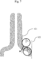
- r 2 can also be determined geometrically by applying a circle adjacent to a straight line extending the outer contour of the body region and by increasing the diameter of the circle step by step until a maximum overlap between the outer contour of the shoulder region and a segment of the circle is reached (see again Figure 7 ). The radius of the thus obtained circle is r 2 .
- n s is determined in a direction perpendicular to that line.
- a line is drawn perpendicular to that tangent in P 3
- P 4 The point at which this perpendicular line crosses the inner surface.
- a third line is drawn that runs parallel to tangent and that goes through P 4 .
- n s corresponds to the distance between these two parallel lines.
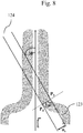
- the inner shoulder angle ⁇ is measured at that point of the inner shoulder whose distance to the syringe axis L barrel is [ d c,inner + d 2.inner )/4 as this is shown in Figure 9 .
- d c,inner corresponds to the inner diameter of the channel at the top end of the syringe barrel and d 2,inner corresponds to the inner diameter of the body region.
- ⁇ is determined using an offline camera. A line is drawn on the longest straight part between the two radii. The angle is then measured by applying a horizontal line.
- the cone breaking force is determined according to ISO 11040-4: 2015 C.2, wherein the following parameters have been selected: Method Measurement system Load cell Test speed sampling rate Distance from tip end Closure selected values tensile and compression testing machine ⁇ 2 kN 25m / min ⁇ 100 Hz 2-3 mm LLA only
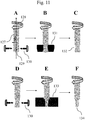
- a glass tube having an outer diameter d 2 of 10.85 mm and a wall thickness n 2 of 1.1 mm made of borosilicate glass is loaded into the head of a rotary machine. While rotating around its longitudinal axis L tube one end of the glass tube (i. e. at the end of which the Luer cone will be localized) is heated to its softening point with flames (see Fig. 11A ). While the glass tube is rotating around its longitudinal axis the end that has been heated is shaped using molding tools that act on predetermined positions of the outer surface of the glass tube at the first end to form the cone region that also comprises a constriction region and the shoulder region.
- a first molding tool is pressed against the outer surface of the glass tube at the first end to initiate the formation of the constriction region (see Fig. 11B ).
- the first end is then further heated (see Fig. 11D ) and a set of second molding tools is then pressed against the preformed outer surface of the glass tube at the first end to obtain the final shape of the cone region, the constriction region and the shoulder region (see Figure 11E ).
- the shape of the further molding tools as well as the angle in which these tools are pressed against the molten cone region ensure that the minimum radius of curvature between points P 1 and P 2 is maintained in the desired range.
- the glass tube while rotating around its longitudinal, is cut at a predetermined position above the first end to obtain a glass tube with a length l tube comprising a first end that is cone shaped and second end.
- the glass tube is then heated at the second end, while rotating around its longitudinal, to a temperature above its glass transition temperature with a flame. While the glass tube is still rotating around its longitudinal, the second end is then shaped for the formation of a flinger flange by pressing appropriate molding tools against the outer surface of the glass tube at the second end.
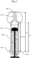
- Figure 1 shows a cross-sectional view of a syringe comprising a glass syringe barrel 100 according to the present invention having the length l 3 and an outer diameter d 2 in the body region 114 into view a plunger stopper 104 has been introduced.
- the syringe barrel 100 comprises a top end 102 with a conically shaper upper portion 102 and a bottom end 103 into which the plunger stopper 104 has been introduced.
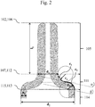
- Figure 2 shows a cross-sectional enlarged view of the top end 102 of the glass syringe barrel 100 shown in Figure 1 that comprises the conically shaped upper portion 101 (the section of the glass syringe barrel 100 that is shown in Figure 2 corresponds to the area that is encompassed by the dotted circle in Figure 1 ).
- the conically shaped upper portion 101 of the glass syringe barrel 100 is in the form of a Luer-slip style connector and comprises in the embodiment shown in Figure 2 a cone region 105 having a first end 106 that corresponds to the top end 102 of the glass syringe barrel 100 and a second end 107, wherein the cone region 105 has a length l 1 and an outer diameter d 1 at the second end 107.
- Adjacent to the cone region 105 is a shoulder region 111 having a first end 112 that is adjacent to the second end 107 of the cone region 105 and a second end 113, wherein the outer contour of the shoulder region 111 comprises a concave and substantially circular arc-shaped area c 1 (see the dashed and bold marked line in the upper part of the right side of the shoulder region) with an outer radius r 1 beginning below the second end 110 of the constriction region 108 and a convex and substantially circular arc-shaped area c 2 (see the continuous and bold marked line in the upper part of the right side of the shoulder region) with an outer radius r 2 beginning above the second end 113.
- the shoulder region 111 is characterized by an outer shoulder angle ⁇ and an inner shoulder angle ⁇ .
- Adjacent to the should region 111 is a body region 114 (see also Figure 1 ) into which the syringe plunger 104 can be pushed, having a first end 115 that is adjacent to the second end 113 of the shoulder region 111 and a second end 116 that corresponds to the bottom end 103 of the glass syringe barrel 100, wherein the thickness of the glass in the body region 114 is n 2 .
- the diameter d 2 of the body region 114 corresponds to the diameter of the glass tube 126 hat us used to manufacture the glass syringe barrel 100 according to the present invention (see Figure 11 ).
- Figure 3 shows a cross-sectional enlarged view of the top end 102 of a further glass syringe barrel 100 according to the present invention that comprises a conically shaped upper portion 101 in the form of a Luer cone, wherein the glass syringe barrel further comprises a constriction region 108 that is located between the cone region 105 and the should region 111.
- the constriction region 108 comprises a first end 109 that is adjacent to the second end 107 of the cone region 105, a second end 110 that is adjacent to the first end 112 of shoulder region 111 and an outer contour c 3 , wherein the constriction region 108 has a length l 1 ' , a minimum outer diameter d 1 ' ⁇ d 1 below the first end 109 of the constriction region 108 and an outer diameter d 1 " at the second end 110 of the constriction region 108.
- the outer contour c3 of the glass syringe barrel in the constriction region is conically shaped with d 1 ' ⁇ d 1 " and wherein at the second end of the constriction region c 3 merges into c 1 without any offset. It is also preferred that in the constriction region 108 a first line 117 that runs parallel to the longitudinal axis L barrel and a second line 118 that runs parallel to c 3 and that runs in the same plane as the first line 117 include an angle ⁇ , wherein ⁇ is in the range from 1 to 3°.
- Figure 4 shows how to determine the angle ⁇ in the constriction region 108, this angle defining the extend of the conical shape of the constriction region.
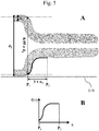
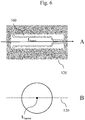
- Figures 6A and 6B show in a side view and in a top view the localization of plane 120 in the glass syringe barrel 100 that is used to determine the local curvature of function f(x) within the range from P 1 to P 2 by means of the approach that is shown in Figures 5A and 5B .
- Plane 120 corresponds to the plane that is centrically located in the glass syringe barrel 100 and that comprises the longitudinal axis L barrel of the glass syringe barrel 100.
- Figure 7 shows how to determine the outer radius r 1 of the concave and substantially circular arc-shaped area c 1 of the shoulder region 111.
- IP first inflection point
- r 2 can be determined geometrically by applying a circle adjacent to a straight line 122 extending the outer contour of the body region 114 and by increasing the diameter of the circle until a maximum overlap between the outer contour of the shoulder region 111 and a segment of the arc is reached.
- the radius of the thus obtained circle is r 2 .
- Figure 8 shows how to determine the thickness n s of the glass in the shoulder region 111.
- n s is measured at that point P 3 of shoulder region at which a tangent at the outer surface for the first time forms an angle of 30° to the syringe axis L barrel as this is shown in Figure 8 .
- n s is determined in a direction perpendicular to that line.
- a line is drawn perpendicular to that tangent in P 3 .
- P 4 The point at which this perpendicular line crosses the inner surface.
- a third line is drawn that runs parallel to tangent and that goes through P 4 .
- n s corresponds to the distance between these two parallel lines.
- Figure 9 shows how to determine the inner shoulder angle ⁇ .
- ⁇ is measured at that point of the inner shoulder whose distance to the syringe axis L barrel is [ d c,inner + d 2.inner )/4.
- d c,inner corresponds to the inner diameter of the channel 125 at the top end 102 of the glass syringe barrel 100 and
- d 2,inner corresponds to the inner diameter of the body region 114.
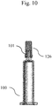
- Figure 10 shows a glass syringe barrel 100 according to the present invention with a tip cap 126 attached to the conically shaped upper portion 101.
- FIGS 11A-F illustrate steps I), II) and III) of process 1 for the preparation of a glass syringe barrel 100 according to the present invention.
- a glass tube 127 having a longitudinal axis L tube , a first end 129 and a further end 128 is loaded into a machine, preferably a rotary machine, the glass tube 127 having a wall thickness n 2 and an outer diameter d 2 .
- the glass tube 127 while rotating around its longitudinal axis, is heated to a temperature above its glass transition temperature, preferably above its softening temperature, with a heating element 130 (indicated by the candle flames shown on the left in Figure 11A ), preferably with a flame 130.
- the first end 129 that has been heated is shaped by using molding tools 131 that act on predetermined positions of the outer surface of the glass tube 127 at the first end 129 to form a conically shaped upper portion 101 as shown in Figures 11B and 11E .
- the conically shaped upper portion 101 is formed in two steps: in a first step using a first set of molding tools 131 a Luer end precursor 132 is formed that does not have the final shape of the conically shaped upper portion 101 according to the present invention (see Figures 11B and 11C ).
- the Luer cone precursor 132 is then again heated as shown in Figure 11D and is then finally shaped using a second set of molding tools 133 as shown in Figure 11E to obtain a glass tube 127 with finished conically shaped upper portion 101 (see Figure 11E ).
- the shape of the molding tools 131,133 that are used in this shaping process as well as the extent to which they are pressed against the molten region of the glass tube 127 have to be adopted to ensure that the desired geometry particularly in the transition state between the shoulder region 111 and the cone region 105 (or, if present, the constriction region 108) is obtained.
- the glass tube with finished conically shaped upper portion 101 is cut at a predetermined position above the first end 129 to obtain a glass tube with a length l tube comprising a first end 128 that has been shaped by means of process steps I) to III) and second end.
- the second end of the glass tube while rotating around its longitudinal axis, is heated to a temperature above its glass transition temperature, preferably above its softening temperature, with a heating element, preferably with a flame.
Description
- The present invention relates to a glass syringe barrel with an at least partially conically shaped upper portion and having a longitudinal axis Lbarrel, the glass syringe barrel comprising a top end through which a liquid can be ejected and a bottom end into which a plunger stopper can be pushed, the glass syringe barrel comprising in a direction from the top end to the bottom i) a cone region, ii) a shoulder region and iii) a body region. The present invention also relates to a plurality of glass syringe barrels and to a syringe that comprises a glass syringe barrel.
- In order to guarantee a reliable use of pharmaceutical products, pre-filled one-time-use syringes are available commercially. They permit a rapid injection of the product that they contain after a comparatively simple manipulation or handling. This sort of pre-filled syringe has a syringe barrel made from glass or polymer with a syringe head formed on it, in which either a syringe needle is integrated or which has a Luer connecting cone of a conical connection, if necessary, a lockable cone connection (Luer lock). A grip plate is mounted on the other open end of the syringe barrel, either formed in one piece with it or put on it as a separate part. An elastomeric piston stopper is slidable through the open end of the syringe barrel. The piston stopper has a threaded blind hole, in which a piston rod with a threaded front end is screwable in various embodiments. The aforementioned single-use syringe, also called a ready-made syringe, with a syringe barrel made of glass, is described in Norm DIN ISO 11040, in which, for example, the syringe barrel is described in part 4. The elastomeric standard piston stopper and standard piston rod made of polymer with a cruciform cross section are described in part 5.
- There are two varieties of Luer taper connections: locking and slipping. "Luer-Lock" style connectors are often generically referred to as "Luer-lock", and "Luer-slip" style connectors may be generically referred to as "slip tip". Luer-lock fittings are securely joined by means of a tabbed hub on the female fitting which screws into threads in a sleeve on the male fitting. Slip tip (Luer-slip) fittings simply conform to Luer taper dimensions and are pressed together and held by friction (they have no threads). A glass syringe designed for a Luer-lock style connector usually is characterized in that it comprises an upper portion that is at least partially conically shaped over which the Luer components are pushed, usually followed by a constriction region in which the diameter is reduced compared to the diameter of the cone region. The reduced diameter in the constriction region creates a notch around the conically shaped upper portion, which allows the Luer-lock adapter (which is a sleeve made of plastic that comprises the threads) to "snap in" and thus securely hold these components on the syringe.
- In a glass syringe barrel comprising designed for a Luer-lock style connector or for a Luer-slip style connector the outer diameter of the conically upper portion is only about 4 mm with a wall thickness of the glass in the cone region of only about 1 to about 2 mm. Accordingly, such glass syringe barrels are very susceptible to mechanical stresses in the cone region, such as those mechanical stresses which occur when a Luer adapter is attached to the conically shaped upper portion, when a needle in a Luer adapter that is attached to the Luer cone is inserted into human or animal tissue as part of the intended use of such a syringe, or when such glass syringe barrels are transported in a packaging unit that contains large number of such syringes packaged in a confined space.
-
EP 0 845 439 A1 discloses a glass capillary tube that is shaped so that its inner diameter is narrowed through a transit contour with a continuous tapering over a given length into an end section with a smaller and constant inner diameter, wherein the structure of the transit contour shape is set by certain mathematical function. -
JP 2015/73635 A -
US 5,851,201 discloses a syringe, comprising a hollow barrel with an open proximal end and a conical distal tip, a plunger assembly inserted into the open proximal end, the plunger assembly and the hollow barrel defining an internal variable volume chamber for retaining fluid, wherein the exterior surface of the tip is provided with a non-coated texture, such that the force required to disengage the tip from a conically-shaped female fitment when a fluid is present between the tip and the fitment is equal to or greater than the force required to disengage the tip and the fitment when the tip and the fitment are dry, and the force required to disengage the tip from the female fitment in the dry state does not exceed the force required to disengage an identically dimensioned coated tip from the female fitment in the dry state. - International Standard ISO 11040-4 (Third Edition 2015-04-01 discloses certain standards glass barrels for injectables and sterilized subassembled syringes ready for filling must fulfil.
- In general, it is an object of the present invention to at least partly overcome a disadvantage arising from the prior art. It is a further object of the present invention to provide a glass syringe barrel comprising an at least partially conically shaped upper portion, particularly a Luer cone designed for a Luer-lock style connector or for a Luer-slip style connector, which, compared to similar glass syringe barrels known from the prior art, has an improved resistance towards pressure that is applied onto the cone region of the glass syringe barrel. It is a further object of the present invention to provide a glass syringe barrel comprising an at least partially conically shaped upper portion, particularly a Luer designed for a Luer-lock style connector or for a Luer-slip style connector, which, compared to similar glass syringe barrels known from the prior art, has an improved resistance towards pressure that is applied onto the cone region of the glass syringe barrel and which has been prepared by a process as simple as possible, preferably from prefabricated glass tubing by shaping and separation. It is a further object to provide a process for the preparation of a glass syringe barrel comprising an at least partially conically shaped upper portion, particularly a Luer cone designed for a Luer-lock style connector or for a Luer-slip style connector, which, compared to similar glass syringe barrels known from the prior art, has an improved resistance towards pressure that is applied onto the cone region of the glass syringe from prefabricated glass tubing by shaping and separation, wherein no additional process steps such as a modification of the glass surface or the thickening of the glass in the cone- and/or shoulder region are required.
- A contribution to at least partly solving at least one, preferably more than one, of the above objects is made by the appended independent claim. The dependent claims provide preferred embodiments which contribute to at least partly solving at least one of the objects.
- A contribution to solving at least one of the objects according to the invention is made by an
embodiment 1 of a glass syringe barrel with an at least partially conically shaped upper portion, the glass syringe barrel having a longitudinal axis Lbarrel and comprising a top end through which a liquid can be ejected and a bottom end into which a plunger stopper can be pushed, the glass syringe barrel comprising in a direction from the top end to the bottom end: - i) a cone region having a first end that corresponds to the top end of the glass syringe barrel and a second end, wherein the cone region has a length I1 and an outer diameter d1 at the second end;
- ii) a shoulder region having a first end that is adjacent to the second end of the cone region and a second end, wherein the outer contour of the shoulder region comprises a concave and substantially circular arc-shaped area c1 with an outer radius r1 beginning below the second end of the cone region and a convex and substantially circular arc-shaped area c2 with an outer radius r2 beginning above the second end of the shoulder region;
- iii) a body region having a first end that is adjacent to the second end of the shoulder region and a second end that preferably corresponds to the bottom end of the glass syringe barrel, wherein the body region has an outer diameter d2 and a glass thickness n2 ;
- A contribution to solving at least one of the objects according to the invention is also made by an
embodiment 1 of aplurality 1 of glass syringe barrels, each glass syringe barrel having an at least partially conically shaped upper portion and each glass syringe barrel having a longitudinal axis Lbarrel and comprising a top end through which a liquid can be ejected and a bottom end into which a plunger stopper can be pushed, each glass syringe barrel comprising in a direction from the top end to the bottom end: - i) a cone region having a first end that corresponds to the top end of the glass syringe barrel and a second end, wherein the cone region has a length I1 and an outer diameter d1 at the second end;
- ii) a shoulder region having a first end that is adjacent to the second end of the cone region and a second end, wherein the outer contour of the shoulder region comprises a concave and substantially circular arc-shaped area c1 with an outer radius r1 beginning below the second end of the cone region and a convex and substantially circular arc-shaped area c2 with an outer radius r2 beginning above the second end of the shoulder region;
- iii) a body region having a first end that is adjacent to the second end of the shoulder region and a second end that corresponds to the bottom end of the glass syringe barrel, wherein the body region has an outer diameter d2 and a glass thickness n2 ;
- if the glass syringe barrel is placed on a plane horizontal substrate with the outer surface of the body region on it, within any given cross-section of the glass syringe barrel that is located in a plane being centrically located in the glass syringe barrel and comprising the longitudinal axis Lbarrel of the glass syringe barrel, f(x) defines the vertical distance between the substrate and the outer surface of the glass syringe barrel at a given position x,
- k(x) = |f"(x)/[1 + f'(x)2]3/2| defines the absolute value of the curvature of f(x) at a given position x, and
- in the interval between x = P1 and x = P2 for any concave curvature in this interval the minimum value for (1/k(x))/n2 2 is at least 0.5 mm-1, preferably at least 0.6 mm-1, more preferably at least 0.75 mm-1, even more preferably at least 0.85 mm-1 and most preferably at least 1.0 mm-1, wherein P1 defines the x-position at which the outer diameter of the glass syringe barrel is 0.95 × d2 and P2 is P1 + 3 × n2 .
- A contribution to solving at least one of the objects according to the invention is also made by an
embodiment 1 of aplurality 2 of glass syringe barrels, each glass syringe barrel having an at least partially conically shaped upper portion and each glass syringe barrel having a longitudinal axis Lbarrel and comprising a top end through which a liquid can be ejected and a bottom end into which a plunger stopper can be pushed, each glass syringe barrel comprising in a direction from the top end to the bottom end: - i) a cone region having a first end that corresponds to the top end of the glass syringe barrel and a second end, wherein the cone region has a length l1 and an outer diameter d1 at the second end;
- ii) a shoulder region having a first end that is adjacent to the second end of the cone region and a second end, wherein the outer contour of the shoulder region comprises a concave and substantially circular arc-shaped area c1 with an outer radius r1 beginning below the second end of the cone region and a convex and substantially circular arc-shaped area c2 with an outer radius r2 beginning above the second end of the shoulder region;
- iii) a body region having a first end that is adjacent to the second end of the shoulder region and a second end that corresponds to the bottom end of the glass syringe barrel, wherein the body region has an outer diameter d2 and a glass thickness n2 ;
wherein the following conditions are fulfilled:- if the glass syringe barrel is placed on a plane horizontal substrate with the outer surface of the body region on it, within any given cross-section of the glass syringe barrel that is located in a plane being centrically located in the glass syringe barrel and comprising the longitudinal axis Lbarrel of the glass syringe barrel, f(x) defines the vertical distance between the substrate and the outer surface of the glass syringe barrel at a given position x, wherein k(x) = |f'(x)/[1 + f(x)2]3/2| defines the absolute value of the curvature of f(x) at a given position x, and wherein in the interval between x = P1 and x = P2 for any concave curvature in this interval the minimum value for (1/k(x))/n2 2 is at least 0.5 mm-1 , wherein P1 defines the x-position at which the outer diameter of the glass syringe barrel is 0.95 x d2 and P2 is P1 + 3 x n2, such that
- for the Luer cone breaking resistance the 1 % quantile of the glass syringe barrels contained in the plurality of glass syringe barrels is at least 50 N, preferably at least 65 N, more preferably at least 80 N, even more preferably at least 95 N and most preferably at least 110N, and/or
- for the Luer cone breaking resistance the 50 % quantile of the glass syringe barrels contained in the plurality of glass syringe barrels is at least 145 N, preferably at least 175 N, more preferably at least 205 N, even more preferably at least 230 N and most preferably at least 270 N.
- if the glass syringe barrel is placed on a plane horizontal substrate with the outer surface of the body region on it, within any given cross-section of the glass syringe barrel that is located in a plane being centrically located in the glass syringe barrel and comprising the longitudinal axis Lbarrel of the glass syringe barrel, f(x) defines the vertical distance between the substrate and the outer surface of the glass syringe barrel at a given position x, wherein k(x) = |f'(x)/[1 + f(x)2]3/2| defines the absolute value of the curvature of f(x) at a given position x, and wherein in the interval between x = P1 and x = P2 for any concave curvature in this interval the minimum value for (1/k(x))/n2 2 is at least 0.5 mm-1 , wherein P1 defines the x-position at which the outer diameter of the glass syringe barrel is 0.95 x d2 and P2 is P1 + 3 x n2, such that
- A plurality of glass syringe barrels has a 1 % quantile of 50 N for the Luer cone breaking resistance if at least 1 % of the glass syringe barrels have a Luer cone breaking resistance of 50 N or less and if at least 99 % of have a Luer cone breaking resistance of 50 N or more. A plurality of glass syringe barrels has a 50 % quantile of 145 N for the Luer cone breaking resistance if at least 50 % of the glass syringe barrels have a Luer cone breaking resistance of 145 N or less and if at least 50 % of have a Luer cone breaking resistance of 145 N or more.
- "A plurality of glass syringes" in the sense of the present invention preferably comprises at least 10 glass syringes, preferably at least 25 glass syringes, more preferably at least 50 glass syringes, even more preferably at least 100 glass syringes even more preferably at least 200 glass syringes and most preferably at least 400 glass syringes. Furthermore, the plurality of glass syringes preferably has been collected arbitrarily and particularly has not been selected with regard to any property. For example, the plurality glass syringes may be the group of syringes which are packed together in a typical transport tray.
- In an
embodiment 2 of theglass syringe barrel 1 according to the invention or of theplurality glass syringe barrel 1 or theplurality embodiment 1, wherein for theglass syringe barrel 1 or for at least 75 %, preferably for at least 85 %, more preferably for at least 95 % and most preferably for each glass syringe barrel contained in theplurality - In an
embodiment 3 of theglass syringe barrel 1 according to the invention or of theplurality glass syringe barrel 1 or theplurality embodiment glass syringe barrel 1 or for at least 75 %, preferably for at least 85 %, more preferably for at least 95 % and most preferably for each glass syringe barrel contained in theplurality - In an embodiment 4 of the
glass syringe barrel 1 according to the invention or of theplurality glass syringe barrel 1 or theplurality embodiments 1 to 3, wherein for theglass syringe barrel 1 or for at least 75 %, preferably for at least 85 %, more preferably for at least 95 % and most preferably for each glass syringe barrel contained in theplurality - In an embodiment 5 of the
glass syringe barrel 1 according to the invention or of theplurality glass syringe barrel 1 or theplurality embodiments 1 to 4, wherein the glass syringe barrel further comprises a constriction region that is located between the cone region and the shoulder region, the constriction region having a first end that is adjacent to the second end of the cone region, a second end that is adjacent to the first end of shoulder region and an outer contour c3 , wherein the constriction region has a length l1 ', a minimum outer diameter d1' < d1 below the first end of the constriction region and an outer diameter d1 " at the second end of the constriction region. - In an embodiment 6 of the
glass syringe barrel 1 according to the invention or of theplurality glass syringe barrel 1 or theplurality - In an embodiment 7 of the
glass syringe barrel 1 according to the invention or of theplurality glass syringe barrel 1 or theplurality glass syringe barrel 1 or for at least 75 %, preferably for at least 85 %, more preferably for at least 95 % and most preferably for each glass syringe barrel contained in theplurality - In an embodiment 8 of the
glass syringe barrel 1 according to the invention or of theplurality glass syringe barrel 1 or theplurality embodiments 1 to 7, wherein for theglass syringe barrel 1 or for at least 75 %, preferably for at least 85 %, more preferably for at least 95 % and most preferably for each glass syringe barrel contained in theplurality - In an embodiment 9 of the
glass syringe barrel 1 according to the invention or of theplurality glass syringe barrel 1 or theplurality glass syringe barrel 1 or for at least 75 %, preferably for at least 85 %, more preferably for at least 95 % and most preferably for each glass syringe barrel contained in theplurality - In an
embodiment 10 of theglass syringe barrel 1 according to the invention or of theplurality glass syringe barrel 1 or theplurality embodiments 1 to 9, wherein for theglass syringe barrel 1 or for at least 75 %, preferably for at least 85 %, more preferably for at least 95 % and most preferably for each glass syringe barrel contained in theplurality - In an
embodiment 11 of theglass syringe barrel 1 according to the invention or of theplurality glass syringe barrel 1 or theplurality embodiments 1 to 10, wherein for theglass syringe barrel 1 or for at least 75 %, preferably for at least 85 %, more preferably for at least 95 % and most preferably for each glass syringe barrel contained in theplurality - In an
embodiment 12 of theglass syringe barrel 1 according to the invention or of theplurality glass syringe barrel 1 or theplurality embodiments 1 to 11, wherein the outer surface of glass syringe barrel in the cone region is roughened or is provided with a coating. - In an
embodiment 13 of theglass syringe barrel 1 according to the invention or of theplurality glass syringe barrel 1 or theplurality glass syringe barrel 1 or for at least 75 %, preferably for at least 85 %, more preferably for at least 95 % and most preferably for each glass syringe barrel contained in theplurality - In an embodiment 14 of the
glass syringe barrel 1 according to the invention or of theplurality glass syringe barrel 1 or theplurality glass syringe barrel 1 or in at least 75 %, preferably for at least 85 %, more preferably for at least 95 % and most preferably in each glass syringe barrel contained in theplurality - In an embodiment 15 of the
glass syringe barrel 1 according to the invention or of theplurality glass syringe barrel 1 or theplurality glass syringe barrel 1 or in at least 75 %, preferably for at least 85 %, more preferably for at least 95 % and most preferably in each glass syringe barrel contained in theplurality - In an embodiment 16 of the
glass syringe barrel 1 according to the invention or of theplurality glass syringe barrel 1 or theplurality embodiments 1 to 15, wherein in theglass syringe barrel 1 or in at least 75 %, preferably for at least 85 %, more preferably for at least 95 % and most preferably in each glass syringe barrel contained in theplurality - In an embodiment 17 of the
glass syringe barrel 1 according to the invention or of theplurality glass syringe barrel 1 or theplurality embodiments 1 to 16, wherein in theglass syringe barrel 1 or in at least 75 %, preferably for at least 85 %, more preferably for at least 95 % and most preferably in each glass syringe barrel contained in theplurality - In an embodiment 18 of the
glass syringe barrel 1 according to the invention or of theplurality glass syringe barrel 1 or theplurality embodiments 1 to 17, wherein ns is the glass thickness in the shoulder region, measured at the point of the inner shoulder surface at which the surface for the first time forms an angle of 30° with longitudinal axis Lbarrel, and wherein in theglass syringe barrel 1 or in at least 75 %, preferably for at least 85 %, more preferably for at least 95 % and most preferably in each glass syringe barrel contained in theplurality - In an embodiment 19 of the
glass syringe barrel 1 according to the invention or of theplurality glass syringe barrel 1 or theplurality embodiments 1 to 18, wherein l2 is the length of the body region and wherein in theglass syringe barrel 1 or in at least 75 %, preferably for at least 85 %, more preferably for at least 95 % and most preferably in each glass syringe barrel contained in theplurality - In an embodiment 20 of the
glass syringe barrel 1 according to the invention or of theplurality glass syringe barrel 1 or theplurality embodiments 1 to 19, wherein in theglass syringe barrel 1 or in at least 75 %, preferably for at least 85 %, more preferably for at least 95 % and most preferably in each glass syringe barrel contained in theplurality - In an embodiment 21 of the
glass syringe barrel 1 according to the invention or of theplurality glass syringe barrel 1 or theplurality embodiments 1 to 20, wherein the glass syringe barrel has a nominal volume V and wherein in theglass syringe barrel 1 or in at least 75 %, preferably for at least 85 %, more preferably for at least 95 % and most preferably in each glass syringe barrel contained in theplurality - In an embodiment 22 of the
glass syringe barrel 1 according to the invention or of theplurality glass syringe barrel 1 or theplurality embodiments 1 to 21, wherein the glass syringe barrel has a length l3, measured as the distance between the top end and the bottom end, and wherein in theglass syringe barrel 1 or in at least 75 %, preferably for at least 85 %, more preferably for at least 95 % and most preferably in each glass syringe barrel contained in theplurality - In an embodiment 24 of the
glass syringe barrel 1 according to the invention or of theplurality glass syringe barrel 1 or theplurality embodiments 1 to 23, wherein theglass syringe barrel 1 or at least 75 %, preferably at least 85 %, more preferably at least 95 % and most preferably each glass syringe barrel contained in theplurality - In an embodiment 24 of the
glass syringe barrel 1 according to the invention or of theplurality glass syringe barrel 1 or theplurality embodiments 1 to 23, wherein the glass syringe barrel is designed for a Luer-slip style connector and is sealed with a tip cap that is attached to the at least partially conically shaped upper portion. - In an embodiment 25 of the
glass syringe barrel 1 according to the invention or of theplurality glass syringe barrel 1 or theplurality embodiments 1 to 24, wherein the glass syringe barrel is designed for a Luer-lock style connector and comprises a Luer-lock adapter that is attached to the at least partially conically shaped upper portion. - In an embodiment 26 of the
glass syringe barrel 1 according to the invention or of theplurality glass syringe barrel 1 or theplurality embodiments 1 to 25, wherein a needle is attached to the at least partially conically shaped upper portion via a Luer connector and wherein the needle is sealed with a needle cap. - In an embodiment 28 of the
glass syringe barrel 1 according to the invention or of theplurality glass syringe barrel 1 or theplurality embodiments 1 to 27, wherein the syringe further comprises - iv) a flange region having a first end that is adjacent to the second end of the body region and a second end that comprises a finger flange and that corresponds to the bottom end of the glass syringe barrel, wherein the flange region has an outer diameter d3 > d2 .
- In an embodiment 29 of the
glass syringe barrel 1 according to the invention or of theplurality glass syringe barrel 1 or theplurality embodiments 1 to 28, wherein the glass is of a type selected from the group consisting of is selected from the group consisting of a borosilicate glass, an aluminosilicate glass, soda lime glass and fused silica. - In an embodiment 30 of the
glass syringe barrel 1 according to the invention or of theplurality glass syringe barrel 1 or theplurality embodiments 1 to 29, wherein the glass syringe barrel comprises a coating that at least partially superimposes the interior surface of the body region. - An exemplification useful for understanding the invention includes an example 1 of a process or making an item, preferably a glass syringe barrel, more preferably a
glass syringe barrel 1 according to the invention, comprising as process steps - I) loading a glass tube having a longitudinal axis Ltube (that corresponds to Lbarrel in the finished glass syringe barrel), a first end and a further end into a machine, preferably a rotary machine, the glass tube having a wall thickness n2 and an outer diameter d2 ;
- II) heating the first end of the glass tube, while rotating around its longitudinal axis, to a temperature above its glass transition temperature, preferably above its softening temperature, with a heating element, preferably with a flame;
- III) while the glass tube is rotating around its longitudinal axis, shaping the first end that has been heated using one or more molding tools that act on predetermined positions of the outer surface of the glass tube at the first end to form
- i) a cone region having a first end that corresponds to the top end of the glass syringe barrel and a second end, wherein the cone region has a length l1 and an outer diameter d1 at the second end;
- ii) a shoulder region having a first end that is adjacent to the second end of the cone region and a second end, wherein the outer contour of the shoulder region comprises a concave and substantially circular arc-shaped area c1 with an outer radius r1 beginning below the second end of the cone region and a convex and substantially circular arc-shaped area c2 with an outer radius r2 beginning above the second end of the shoulder region;
- iii) a body region having a first end that is adjacent to the second end of the shoulder region and a second end that preferably corresponds to the bottom end of the glass syringe barrel, wherein the body region has an outer diameter d2 and a glass thickness n2;
- if the shaped glass tube is placed on a plane horizontal substrate with the outer surface of the body region on it, within any given cross-section of the glass syringe barrel that is located in a plane being centrically located in the glass syringe barrel and comprising the longitudinal axis Ltube of the shaped glass tube, f(x) defines the vertical distance between the substrate and the outer surface of the glass syringe barrel at a given position x,
- k(x) = |f(x)/[1 + f'(x)2]3/2| defines the absolute value of the curvature of f(x) at a given position x, and
- in the interval between x = P1 and x = P2 for any concave curvature in this interval the minimum value for (1/k(x))/n2 2 is at least 0.5 mm-1, preferably at least 0.6 mm-1, more preferably at least 0.75 mm-1, even more preferably at least 0.85 mm-1 and most preferably at least 1.0 mm-1, wherein P1 defines the x-position at which the outer diameter of the glass syringe barrel is 0.95 × d2 and P2 is P1 + 3 × n2 .
- In an example 2 of the
process 1 useful for understanding the invention, theprocess 1 is designed according to its example 1, wherein shaping in process step III) is performed in such a way that in the interval between x = P1 and x = P2 the maximum value of the first derivative f'(x)max of f(x) is less than 18, even more preferably less than 15, even more preferably less than 10 and most preferably less than 5. - In an example 3 of the
process 1 useful for understanding the invention, theprocess 1 is designed according to its example 1 or 2, wherein shaping in process step III) is performed in such a way that r1 is in the range from 0.5 to 3 mm, preferably in the range from 0.5 to 2.5 mm, more preferably in the range from 0.6 to 2 mm, even more preferably in the range from 0.7 to 1.8 mm and most preferably in the range from 0.8 to 1.5 mm. - In an example 4 of the
process 1 useful for understanding the invention, theprocess 1 is designed according to anyone of its examples 1 to 3, wherein shaping in process step III) is performed in such a way that r2 is in the range from 1.2 to 3.1 mm, preferably in the range from 1.4 to 2.9 mm, more preferably in the range from 1.6 to 2.7 mm, even more preferably in the range from 1.8 to 2.5 mm and most preferably in the range from 2.0 to 2.3 mm. - In an example 5 of the
process 1 useful for understanding the invention, theprocess 1 is designed according to anyone of its examples 1 to 4, wherein d2 is in the range from 6 to 15 mm, preferably in the range from 6.5 to 14 mm, more preferably in the range from 7 to 13 mm, even more preferably in the range from 7.5 to 12 mm and most preferably in the range from 8 to 11 mm. - In an example 6 of the
process 1 useful for understanding the invention, theprocess 1 is designed according to anyone of its examples 1 to 5, wherein n2 is in the range from 0.6 to 1.6 mm, preferably in the range from 0.7 to 1.5 mm, more preferably in the range from 0.8 to 1.4 mm, even more preferably in the range from 0.9 to 1.3 mm and most preferably in the range from 1 to 1.2 mm. - In an example 7 of the
process 1 useful for understanding the invention, theprocess 1 is designed according to anyone of its examples 1 to 6, wherein shaping in process step III) is performed in such a way that a constriction region is formed that is located between the cone region and the shoulder region, the constriction region having a first end that is adjacent to the second end of the cone region, a second end that is adjacent to the first end of shoulder region and an outer contour c3 , wherein the constriction region has a length l1', a minimum outer diameter d1' < d1 below the first end of the constriction region and an outer diameter d1 " at the second end of the constriction region. - In an example 8 of the
process 1 useful for understanding the invention, theprocess 1 is designed according to its example 7, wherein shaping in process step III) is performed in such a way that the outer contour c3 of the glass syringe barrel in the constriction region is conically shaped with d1' < d1 " and wherein at the second end of the constriction region c3 merges into c1 without any offset. - In an example 9 of the
process 1 useful for understanding the invention, theprocess 1 is designed according to its example 8, wherein shaping in process step III) is performed in such a way that in the constriction region a first line that runs parallel to the longitudinal axis Lbarrel and a second line that runs parallel to c3 and that runs in the same plane as the first line include an angle γ, and wherein γ is in the range from 0.3 to 2.5°, preferably in the range from 0.5 to 2.0° and most preferably in the range from 0.7 to 1.5°. - In an example 10 of the
process 1 useful for understanding the invention, theprocess 1 is designed according to anyone of its examples 1 to 9, wherein shaping in process step III) is performed in such a way that l1 or, in case of a constriction region, the total length l1 + l1 ', is in the range from 8 to 12 mm, preferably in the range from 8.75 to 10.5 mm, more preferably in the range from 8.5 to 10 mm, even more preferably in the range from 8.6 to 9.8 mm, even more preferably in the range from 8.7 to 9.6 and most preferably in the range from 9.4 to 9.6 mm. - In an example 11 of the
process 1 useful for understanding the invention, theprocess 1 is designed according to anyone of its examples 7 to 10, wherein shaping in process step III) is performed in such a way that l1 ' is in the range from 1 to 3 mm, preferably in the range from 1.1 to 2.5 mm, more preferably in the range from 1.2 to 2 mm, even more preferably in the range from 1.3 to 1.8 mm and most preferably in the range from 1.4 to 1.6 mm. - In an example 12 of the
process 1 useful for understanding the invention, theprocess 1 is designed according to anyone of its examples 1 to 11, wherein shaping in process step III) is performed in such a way that d1 is in the range from 4 to 5 mm, preferably in the range from 4.1 to 4.8 mm, more preferably in the range from 4.2 to 4.6 mm, even more preferably in the range from 4.3 to 4.45 mm and most preferably in the range from 4.40 to 4.42 mm. Preferably, d1 is the maximum outer diameter of the cone region. It is furthermore preferred that the second end of the cone region preferably corresponds to the point at which the outer diameter d1 exceeds a value of 4.4 mm - In an example 13 of the
process 1 useful for understanding the invention, theprocess 1 is designed according to anyone of its examples 7 to 12, wherein shaping in process step III) is performed in such a way that s d1' is in the range from 3.4 to 5.2 mm, preferably in the range from 3.6 to 5 mm, more preferably in the range from 3.8 to 4.8 mm, even more preferably in the range from 4 to 4.6 mm and most preferably in the range from 4.2 to 4.4 mm. - In an example 14 of the
process 1 useful for understanding the invention, theprocess 1 is designed according to anyone of its examples 7 to 13, wherein shaping in process step III) is performed in such a way that the maximum thickness of the glass in the constriction region is in the range from 1.3 to 2.1 mm, preferably in the range from 1.4 to 2 mm, more preferably in the range from 1.5 to 1.9 mm, even more preferably in the range from 1.6 to 1.8 mm and most preferably in the range from 1.65 to 1.75 mm. - In an example 15 of the
process 1 useful for understanding the invention, theprocess 1 is designed according to anyone of its examples 7 to 13, wherein shaping in process step III) is performed in such a way that the minimum thickness of the glass in the constriction region is in the range from 1.1 to 1.9 mm, preferably in the range from 1.2 to 1.8 mm, more preferably in the range from 1.3 to 1.7 mm, even more preferably in the range from 1.4 to 1.6 mm and most preferably in the range from 1.45 to 1.55 mm. - In an example 16 of the
process 1 useful for understanding the invention, theprocess 1 is designed according to anyone of its examples 1 to 15, wherein shaping in process step III) is performed in such a way that the shoulder region is characterized by an outer shoulder angle α in the range from 6 to 28°, preferably in the range from 8 to 22°, more preferably in the range from 9 to 16°, even more preferably in the range from 10 to 15° and most preferably in the range from 11 to 14°. - In an example 17 of the
process 1 useful for understanding the invention, theprocess 1 is designed according to anyone of its examples 1 to 16, wherein shaping in process step III) is performed in such a way that the shoulder region is characterized by an inner shoulder angle β in the range from 22 to 50° preferably in the range from 25 to 40°, more preferably in the range from 26 to 35°, even more preferably in the range from 27 to 32° and most preferably in the range from 28 to 31°. - In an example 18 of the
process 1 useful for understanding the invention, theprocess 1 is designed according to anyone of its examples 1 to 17, wherein shaping in process step III) is performed in such a way that, if ns is the glass thickness in the shoulder region, measured at the point of the inner shoulder surface at which the surface for the first time forms an angle of 30° with longitudinal axis Lbarrel, ns is in the range from 1.2 to 2 mm, preferably in the range from 1.3 to 1.8 mm, more preferably in the range from 1.3 to 1.6 mm, even more preferably in the range from 1.35 to 1.5 mm and most preferably in the range from 1.35 to 1.45 mm. - In an example 19 of the
process 1 useful for understanding the invention, theprocess 1 is designed according to anyone of its examples 1 to 18, wherein the process further comprises the step of - IV) roughening the the outer surface of glass syringe barrel in the cone region or applying coating onto the outer surface of glass syringe barrel in the cone region.
- In an example 20 of the
process 1 useful for understanding the invention, theprocess 1 is designed according to anyone of its examples 1 to 19, wherein the process further comprises the step of - V) cutting the glass tube, while rotating around its major axis, at a predetermined position above the first end to obtain a glass tube with a length ltube comprising a first end that has been shaped by means of process steps I) to III) and second end, wherein cutting can be accomplished mechanically by means of a cutting device or can be accomplished thermally by means of a flame with which the glass is molten at the predetermined position and is then pulled apart;
- VI) heating the second end of the glass tube, while rotating around its major axis, to a temperature above its glass transition temperature, preferably above its softening temperature, with a heating element, preferably with a flame;
- VII) while the glass tube is rotating around its major axis, shaping the second end that has been heated using one or more molding tools that act on predetermined positions of the outer surface of the glass tube at the first end to form a finger flange.
- In an example 21 of the
process 1 useful for understanding the invention, theprocess 1 is designed according to anyone of its examples 1 to 20, wherein the glass is of a type selected from the group consisting of is selected from the group consisting of a borosilicate glass, an aluminosilicate glass and fused silica. - In an example 22 of the
process 1 useful for understanding the invention, theprocess 1 is designed according to anyone of its examples 1 to 21, wherein the process further comprises the step of - VIII) superimposing at least a part of the interior surface of the body region with a coating. A contribution to solving at least one of the objects according to the invention is made by an
embodiment 1 of aglass syringe barrel 2 obtainable by the process according to any of its examples 1 to 22. In a preferred embodiment of theglass syringe barrel 2, thisglass syringe barrel 2 shows the technical features of theglass syringe barrel 1 of the invention and the technical features of each glass syringe barrel contained in theplurality - A contribution to solving at least one of the objects according to the invention is made by an
embodiment 1 of a syringe comprising - A) a
glass syringe barrel 1 according to any of its preferred embodiments, aplurality glass syringe barrel 2 according to any of its preferred embodiments; - B) a plunger stopper that has been pushed into the bottom end of the glass syringe barrel or into the bottom end of each of the glass syringe barrels contained in the
plurality - In an
embodiment 2 of the syringe according to the invention, the syringe further comprises - C) a pharmaceutical composition that is filled into at least a part of the inner volume of the body region.
- The glass syringe barrel according to the invention may have any size or shape which the skilled person deems appropriate in the context of the invention. The first end of the glass syringe barrel an opening in the form of a channel located within the cone region through which a pharmaceutical composition that is contained in the glass syringe can be squeezed out of the glass syringe barrel and a second end (that is preferably provided with a finger flange) into which a plunger stopper can be pushed. Preferably, the glass syringe barrel is of a one-piece design that is prepared by providing a glass tube, preferably in form of a hollow cylinder, and forming the conically shaper upper portion, thereby obtaining the cone and the shoulder region (and optionally constriction region) and by forming a finger flange at the opposed end of the glass tube. A preferred glass syringe barrel is a prefilled glass syringe barrel that is filled with a pharmaceutical preparation. Preferably, the glass syringe barrel is rotationally symmetrical around the longitudinal axis Lbarrel that preferably goes perpendicular through the centre of the body region.
- The glass of the glass syringe barrel be any type of glass and may consist of any material or combination of materials which the skilled person deems suitable in the context of the invention. Preferably, the glass is suitable for pharmaceutical packaging. Particularly preferable, the glass is of type I, more preferably type I b, in accordance with the definitions of glass types in section 3.2.1 of the European Pharmacopoeia, 7th edition from 2011. Additionally, or alternatively preferable to the preceding, the glass is selected from the group consisting of a borosilicate glass, an aluminosilicate glass, soda lime glass and fused silica; or a combination of at least two thereof. For the use in this document, an aluminosilicate glass is a glass which has a content of Al2O3 of more than 8 wt.-%, preferably more than 9 wt.-%, particularly preferable in a range from 9 to 20 wt.-%, in each case based on the total weight of the glass. A preferred aluminosilicate glass has a content of B2O3 of less than 8 wt.-%, preferably at maximum 7 wt.-%, particularly preferably in a range from 0 to 7 wt.-%, in each case based on the total weight of the glass. For the use in this document, a borosilicate glass is a glass which has a content of B2O3 of at least 1 wt.-%, preferably at least 2 wt.-%, more preferably at least 3 wt.-%, more preferably at least 4 wt.-%, even more preferably at least 5 wt.-%, particularly preferable in a range from 5 to 15 wt.-%, in each case based on the total weight of the glass. A preferred borosilicate glass has a content of Al2O3 of less than 7.5 wt.-%, preferably less than 6.5 wt.-%, particularly preferably in a range from 0 to 5.5 wt.-%, in each case based on the total weight of the glass. In a further aspect, the borosilicate glass has a content of Al2O3 in a range from 3 to 7.5 wt.-%, preferably in a range from 4 to 6 wt.-%, in each case based on the total weight of the glass.
- A glass which is further preferred according to the invention is essentially free from B. Therein, the wording "essentially free from B" refers to glasses which are free from B which has been added to the glass composition by purpose. This means that B may still be present as an impurity, but preferably at a proportion of not more than 0.1 wt.-%, more preferably not more than 0.05 wt.-%, in each case based on the weight of the glass.
- An important element of the
glass syringe barrel 1 according to the invention, of the glass syringe barrels contained in theplurality 1 of glass syringe barrels according to the invention and of theglass syringe barrel 2 according to the invention is the shape of the outer contour in the shoulder region that is formed in process step III) of theprocess 1 according to the present invention, particularly the outer contour in the concave and substantially circular arc-shaped area of the shoulder region. The outer contour in the shoulder region is characterized in that in the interval between x = P1 and x = P2 for any concave curvature in this interval the minimum value for (1/k(x))/n2 2 is at least 0.5 mm-1, wherein P1 defines the x-position at which the outer diameter of the glass syringe barrel is 0.95 × d2 and P2 is P1 + 3×n2 . Furthermore, if the glass syringe barrel further comprises a constriction region that is localized between the cone region and the shoulder region and that is characterized by an outer contour c3 , it is also preferred that the glass syringe barrel in the constriction region is conically shaped in such a way that the diameter of the constriction region increases towards the shoulder region. In this context it is particularly preferred that the outer contour of the glass syringe barrel at the second end of the constriction region merges into the outer contour of the glass syringe barrel at the first end of the shoulder region without any offset. - In the context of the invention, every liquid pharmaceutical composition which the skilled person deems suitable to be used in a syringe comes into consideration. A pharmaceutical composition is a composition comprising at least one active ingredient. A preferred active ingredient is a vaccine. A further preferred pharmaceutical composition is a parenterialium, i.e. a composition which is intended to be administered via the parenteral route, which may be any route which is not enteral. Parenteral administration can be performed by injection, e.g. using a needle (usually a hypodermic needle) and a syringe.
- The following measurement methods are to be used in the context of the invention. Unless otherwise specified, the measurements have to be carried out at an ambient temperature of 23°C, an ambient air pressure of 100 kPa (0.986 atm) and a relative atmospheric humidity of 50 %.
-
- The local curvature k(x) of the outer contour of the glass syringe barrel in the shoulder region defined by the function f(x) can be determined in a non-destructive manner using a profile projector. This approach is particularly suitable for glass syringe barrels that have been chemically and/or thermally tempered and that therefore cannot be easily sliced in half without the glass cracking or bursting. For determining the local curvature k(x) in a non-destructive manner the outer contour of the glass syringe barrels is visualized using a Mitutoyo PJ-3000 profile projector. The profile projector has a 10X magnification and is operated with transmitted light illumination. The barrels are placed in Hallbrite® BHB (a butyloctyl salicylate obtainable from the Hallstar Company, Chicago, USA), which is filled into a glass bowl. Hallbrite® BHB is used to visualize the outer contour of the barrel. It is ensured that the cross-section of the glass syringe barrel that is inspected in the profile projector corresponds to the plane that is centrically located in the glass syringe barrel and that comprises the longitudinal axis Lbarrel of the glass syringe barrel, i. e. the axis that goes perpendicular through the barrel (see
Figures 6A and 6B ). - To improve the measuring accuracy, the outer contour of the glass syringe barrel in the shoulder region can also be determined from a physical cross-sectional cut parallel along to the longitudinal axis Lbarrel of the barrel (it is again ensured that the cross-section of the glass syringe barrel corresponds to the plane that is centrically located in the glass syringe barrel and that comprises the longitudinal axis glass syringe barrel as shown in
Figure 4 ). For preparation without breakage, the barrel may be embedded into transparent 2-component epoxy resin, for example STRUERS GmbH, EpoFix Resin, or other suitable materials. After curing of the epoxy resin, a cross-sectional cut parallel along to the barrel axis can be achieved by machine-supported sawing, grinding and polishing. Geometrical features of the barrel can then be determined (measured) by means of non-distorting image capturing and geometrical analysis software tools. - The relevant outer contour of the outer surface of the glass syringe barrel in the shoulder region can be extracted and numerically approximated from the images obtained by means of the two approaches described above. For the extraction of the relevant contour of the outer surface, the images undergo the image processing steps implemented in Python [https://www.python.org/] based on the image processing library OpenCV [https://opencv. org/].
- First, the images are denoised using a median filter. The denoised images are then processed with an edge detection algorithm based on a Sobel filter, in which the contours are identified by thresholding the gradient image. For the calculation of slopes and curvatures, the extracted contours are numerically approximated by a univariate spline of order 5. The radii of curvature R(x) are then given by the formula

- In the images obtained by means of the two approaches described above r1 can be determined geometrically by applying a bevel circle to the first inflection point IP (i. e. the first one that appears when entering the outer contour of the shoulder region from the top of the glass syringe barrel) of function f(x) (i. e. the first point at which the condition f"(x) = 0 is fulfilled) and to a straight line extending the outer contour of the cone region, as shown in
Figure 7 . r2 can also be determined geometrically by applying a circle adjacent to a straight line extending the outer contour of the body region and by increasing the diameter of the circle step by step until a maximum overlap between the outer contour of the shoulder region and a segment of the circle is reached (see againFigure 7 ). The radius of the thus obtained circle is r2 . - In the images obtained by means of the two approaches described above the thickness of the glass in the shoulder region ns is measured at that point P3 of shoulder region at which a tangent at the outer surface for the first time forms an angle of 30° to the syringe axis Lbarrel as this is shown in
Figure 8 . ns is determined in a direction perpendicular to that line. For that purpose, a line is drawn perpendicular to that tangent in P3 The point at which this perpendicular line crosses the inner surface is named P4 . A third line is drawn that runs parallel to tangent and that goes through P4 . ns corresponds to the distance between these two parallel lines. - In the images obtained by means of the two approaches described above the inner shoulder angle β is measured at that point of the inner shoulder whose distance to the syringe axis Lbarrel is [dc,inner + d2.inner )/4 as this is shown in
Figure 9 . dc,inner corresponds to the inner diameter of the channel at the top end of the syringe barrel and d2,inner corresponds to the inner diameter of the body region. α is determined using an offline camera. A line is drawn on the longest straight part between the two radii. The angle is then measured by applying a horizontal line. - The cone breaking force is determined according to ISO 11040-4: 2015 C.2, wherein the following parameters have been selected:
Method Measurement system Load cell Test speed sampling rate Distance from tip end Closure selected values tensile and compression testing machine ≤ 2 kN 25m / min ≥ 100 Hz 2-3 mm LLA only - A glass tube having an outer diameter d2 of 10.85 mm and a wall thickness n2 of 1.1 mm made of borosilicate glass is loaded into the head of a rotary machine. While rotating around its longitudinal axis Ltube one end of the glass tube (i. e. at the end of which the Luer cone will be localized) is heated to its softening point with flames (see
Fig. 11A ). While the glass tube is rotating around its longitudinal axis the end that has been heated is shaped using molding tools that act on predetermined positions of the outer surface of the glass tube at the first end to form the cone region that also comprises a constriction region and the shoulder region. In a first step a first molding tool is pressed against the outer surface of the glass tube at the first end to initiate the formation of the constriction region (seeFig. 11B ). The first end is then further heated (seeFig. 11D ) and a set of second molding tools is then pressed against the preformed outer surface of the glass tube at the first end to obtain the final shape of the cone region, the constriction region and the shoulder region (seeFigure 11E ). The shape of the further molding tools as well as the angle in which these tools are pressed against the molten cone region ensure that the minimum radius of curvature between points P1 and P2 is maintained in the desired range. - In a further process step the glass tube, while rotating around its longitudinal, is cut at a predetermined position above the first end to obtain a glass tube with a length ltube comprising a first end that is cone shaped and second end. The glass tube is then heated at the second end, while rotating around its longitudinal, to a temperature above its glass transition temperature with a flame. While the glass tube is still rotating around its longitudinal, the second end is then shaped for the formation of a flinger flange by pressing appropriate molding tools against the outer surface of the glass tube at the second end.
- 500 glass syringe barrels have been prepared in the rotary machine. The outer contour in the shoulder region of one of the glass syringe barrels corresponds to the outer contour of the shoulder region in glass syringe barrels known in the prior art (Comparative Example).
Comparative Example 1 Example 1 r1 [mm] 0.4 1.5 r2 [mm] 1.8 2.3 (1/k(x))/n2 2 [mm-1] 0.17 0.74 f'(x)max 19 4.45 Tip resistance Mean [%] 100 183 Tip resistance Median [N] 142 275 Tip resistance Median [%] 100 194 1 % Quantile [N] 48.3 116.5 - Unless otherwise specified in description or particular Figure:
- Figure 1
- shows a cross-sectional view of a syringe comprising a
glass syringe barrel 100 according to the present invention into view aplunger stopper 104 has been introduced; - Figure 2
- shows a cross-sectional enlarged view of the top end of a
glass syringe barrel 100 according to the present invention that comprises a conically shapedupper portion 101 in the form of a Luer cone; - Figure 3
- shows a cross-sectional enlarged view of the
top end 102 of a furtherglass syringe barrel 100 according to the present invention that comprises a conically shapedupper portion 101 in the form of a Luer cone, wherein the glass syringe barrel further comprises aconstriction region 108 that is located between thecone region 105 and the should region 111.; - Figure 4
- shows the determination of angle γ in the
constriction region 108; - Figure 5A
- shows a cross-sectional enlarged view of the
top end 102 of theglass syringe barrel 100 shown inFigure 3 , wherein in contrast toFigure 3 theglass syringe barrel 100 with the outer surface of thebody region 114 is laying on asubstrate 119; - Figure 5B
- shows function f(x) by means of which the curvature k(x) of the outer contour of the glass syringe barrel in the
shoulder region 111 can be determined; - Figur 6A
- shows in a side view the localization of
plane 120 that is used to determine the local curvature of function f(x) within the range from P1 to P2; - Figure 6B
- shows in a top view the localization of
plane 120 that is used to determine the local curvature of function f(x) within the range from P1 to P2; - Figure 7
- shows the determination of r1;
- Figure 8
- shows the determination of ns;
- Figure 9
- shows the determination of β;
- Figure 10
- shows a
glass syringe barrel 100 according to the present invention with atip cap 117 attached to the conically shapedupper portion 101; - Figures 11A-F
- illustrate steps I), II) and III) of
process 1 for the preparation of aglass syringe barrel 100. -
Figure 1 shows a cross-sectional view of a syringe comprising aglass syringe barrel 100 according to the present invention having the length l3 and an outer diameter d2 in thebody region 114 into view aplunger stopper 104 has been introduced. As can be seen inFigure 1 , thesyringe barrel 100 comprises atop end 102 with a conically shaperupper portion 102 and abottom end 103 into which theplunger stopper 104 has been introduced. -
Figure 2 shows a cross-sectional enlarged view of thetop end 102 of theglass syringe barrel 100 shown inFigure 1 that comprises the conically shaped upper portion 101 (the section of theglass syringe barrel 100 that is shown inFigure 2 corresponds to the area that is encompassed by the dotted circle inFigure 1 ). As can be seen inFigure 2 , the conically shapedupper portion 101 of theglass syringe barrel 100 is in the form of a Luer-slip style connector and comprises in the embodiment shown inFigure 2 acone region 105 having a first end 106 that corresponds to thetop end 102 of theglass syringe barrel 100 and a second end 107, wherein thecone region 105 has a length l1 and an outer diameter d1 at the second end 107. Adjacent to thecone region 105 is ashoulder region 111 having a first end 112 that is adjacent to the second end 107 of thecone region 105 and a second end 113, wherein the outer contour of theshoulder region 111 comprises a concave and substantially circular arc-shaped area c1 (see the dashed and bold marked line in the upper part of the right side of the shoulder region) with an outer radius r1 beginning below the second end 110 of theconstriction region 108 and a convex and substantially circular arc-shaped area c2 (see the continuous and bold marked line in the upper part of the right side of the shoulder region) with an outer radius r2 beginning above the second end 113. As also shown inFigure 2 theshoulder region 111 is characterized by an outer shoulder angle α and an inner shoulder angle β. Adjacent to the shouldregion 111 is a body region 114 (see alsoFigure 1 ) into which thesyringe plunger 104 can be pushed, having a first end 115 that is adjacent to the second end 113 of theshoulder region 111 and asecond end 116 that corresponds to thebottom end 103 of theglass syringe barrel 100, wherein the thickness of the glass in thebody region 114 is n2 . The diameter d2 of thebody region 114 corresponds to the diameter of theglass tube 126 hat us used to manufacture theglass syringe barrel 100 according to the present invention (seeFigure 11 ). -
Figure 3 shows a cross-sectional enlarged view of thetop end 102 of a furtherglass syringe barrel 100 according to the present invention that comprises a conically shapedupper portion 101 in the form of a Luer cone, wherein the glass syringe barrel further comprises aconstriction region 108 that is located between thecone region 105 and the shouldregion 111. Theconstriction region 108 comprises a first end 109 that is adjacent to the second end 107 of thecone region 105, a second end 110 that is adjacent to the first end 112 ofshoulder region 111 and an outer contour c3 , wherein theconstriction region 108 has a length l1', a minimum outer diameter d1' < d1 below the first end 109 of theconstriction region 108 and an outer diameter d1 " at the second end 110 of theconstriction region 108. In this context it is furthermore preferred that the outer contour c3 of the glass syringe barrel in the constriction region is conically shaped with d1' < d1 " and wherein at the second end of the constriction region c3 merges into c1 without any offset. It is also preferred that in the constriction region 108 afirst line 117 that runs parallel to the longitudinal axis Lbarrel and asecond line 118 that runs parallel to c3 and that runs in the same plane as thefirst line 117 include an angle γ, wherein γ is in the range from 1 to 3°.Figure 4 shows how to determine the angle γ in theconstriction region 108, this angle defining the extend of the conical shape of the constriction region. - The
glass syringe barrel 100 according to the present invention is characterized by a well-defined outer contour in the transition region between theshoulder region 111 and, if present, of theconstriction region 108 as well. If theglass syringe barrel 100 is placed on a planehorizontal substrate 119 with the outer surface of thebody region 114 on it as shown inFigure 5A , function f(x) defines the vertical distance between thesubstrate 119 and the outer surface of theglass syringe barrel 100 at a given position x and thus the outer contour of theglass syringe barrel 100 in that area (seeFigure 5B ). From that function the curvature k(x) at a given position x of the outer contour can be calculated as
- The glass syringe barrel according to the present invention is now characterized in that interval between x = P1 and x = P2 for any concave curvature in this interval the minimum value for (1/k(x))/n2 2 is at least 0.5 mm-1, wherein P1 defines the x-position at which the outer diameter of the
glass syringe barrel 100 is 0.95 × d2 and P2 is P1 + 3 × n2 (seeFigure 5A ). -
Figures 6A and 6B show in a side view and in a top view the localization ofplane 120 in theglass syringe barrel 100 that is used to determine the local curvature of function f(x) within the range from P1 to P2 by means of the approach that is shown inFigures 5A and 5B .Plane 120 corresponds to the plane that is centrically located in theglass syringe barrel 100 and that comprises the longitudinal axis Lbarrel of theglass syringe barrel 100. -
Figure 7 shows how to determine the outer radius r1 of the concave and substantially circular arc-shaped area c1 of theshoulder region 111. r1 can be determined geometrically in cross-sectional images of theglass syringe barrel 100 by applying a bevel circle to the first inflection point IP (i. e. the first one that appears when entering the outer contour of theshoulder region 111 from thetop end 102 of the glass syringe barrel 100) of function f(x) (i. e. the first point at which the condition f"(x) = 0 is fulfilled) and to astraight line 121 extending the outer contour of thecone region 105. r2 can be determined geometrically by applying a circle adjacent to astraight line 122 extending the outer contour of thebody region 114 and by increasing the diameter of the circle until a maximum overlap between the outer contour of theshoulder region 111 and a segment of the arc is reached. The radius of the thus obtained circle is r2 . -
Figure 8 shows how to determine the thickness ns of the glass in theshoulder region 111. ns is measured at that point P3 of shoulder region at which a tangent at the outer surface for the first time forms an angle of 30° to the syringe axis Lbarrel as this is shown inFigure 8 . ns is determined in a direction perpendicular to that line. For that purpose, a line is drawn perpendicular to that tangent in P3 . The point at which this perpendicular line crosses the inner surface is named P4 . A third line is drawn that runs parallel to tangent and that goes through P4 . ns corresponds to the distance between these two parallel lines. -
Figure 9 shows how to determine the inner shoulder angle β. β is measured at that point of the inner shoulder whose distance to the syringe axis Lbarrel is [dc,inner + d2.inner )/4. dc,inner corresponds to the inner diameter of thechannel 125 at thetop end 102 of theglass syringe barrel 100 and d2,inner corresponds to the inner diameter of thebody region 114. -
Figure 10 shows aglass syringe barrel 100 according to the present invention with atip cap 126 attached to the conically shapedupper portion 101. -
Figures 11A-F illustrate steps I), II) and III) ofprocess 1 for the preparation of aglass syringe barrel 100 according to the present invention. In process step I) aglass tube 127 having a longitudinal axis Ltube , afirst end 129 and afurther end 128 is loaded into a machine, preferably a rotary machine, theglass tube 127 having a wall thickness n2 and an outer diameter d2 . In process step II) theglass tube 127, while rotating around its longitudinal axis, is heated to a temperature above its glass transition temperature, preferably above its softening temperature, with a heating element 130 (indicated by the candle flames shown on the left inFigure 11A ), preferably with aflame 130. In process step III), while theglass tube 127 is still rotating around its longitudinal axis, thefirst end 129 that has been heated is shaped by usingmolding tools 131 that act on predetermined positions of the outer surface of theglass tube 127 at thefirst end 129 to form a conically shapedupper portion 101 as shown inFigures 11B and 11E . In the process shown inFigure 11 the conically shapedupper portion 101 is formed in two steps: in a first step using a first set of molding tools 131 aLuer end precursor 132 is formed that does not have the final shape of the conically shapedupper portion 101 according to the present invention (seeFigures 11B and 11C ). TheLuer cone precursor 132 is then again heated as shown inFigure 11D and is then finally shaped using a second set ofmolding tools 133 as shown inFigure 11E to obtain aglass tube 127 with finished conically shaped upper portion 101 (seeFigure 11E ). The shape of the molding tools 131,133 that are used in this shaping process as well as the extent to which they are pressed against the molten region of theglass tube 127 have to be adopted to ensure that the desired geometry particularly in the transition state between theshoulder region 111 and the cone region 105 (or, if present, the constriction region 108) is obtained. - In a further process step V) the glass tube with finished conically shaped
upper portion 101, while rotating around its longitudinal axis, is cut at a predetermined position above thefirst end 129 to obtain a glass tube with a length ltube comprising afirst end 128 that has been shaped by means of process steps I) to III) and second end. In a further process step VI) the second end of the glass tube, while rotating around its longitudinal axis, is heated to a temperature above its glass transition temperature, preferably above its softening temperature, with a heating element, preferably with a flame. In a further process step VII), while the glass tube is rotating around its longitudinal axis, the second end that has been heated using is shaped using one or more molding tools that act on predetermined positions of the outer surface of the glass tube at the first end to, for example, form a finger flange (process steps V) to VII) are not shown inFigure 11 ). -
- 100
- glass syringe barrel according to the invention
- 101
- conically shaped upper portion
- 102
- top end
- 103
- bottom end
- 104
- plunger stopper
- 105
- cone region
- 106
- first end of the cone region 105 (= top end 102)
- 107
- second end of the cone region 105 (= first end 112 of the
shoulder region 111 or first end 109 of the constriction region 108) - 111
- shoulder region
- 112
- first end of the shoulder region 111 (= second end 107 of the
cone region 105 or second end 110 of the constriction region 108) - 113
- second end of the shoulder region 111 (= first end 115 of the body region 114)
- 114
- body region
- 115
- first end of the body region 114 (= second end 113 of the shoulder region 111)
- 116
- second end of the body region 114 (= bottom end 103)
- 108
- constriction region
- 109
- first end of the constriction region 108 (= the second end 107 of the cone region 105)
- 110
- second end of the constriction region 108 (= first end 112 of the should region 111)
- 117
- first line
- 118
- second line
- 119
- plane and horizontal substrate
- 120
- cross-sectional plane in the middle of the
glass syringe barrel 100 - 121
- elongation of the outer contour of the
cone region 105 - 122
- elongation of the outer contour of the
body region 114 - 123
- tangent at the outer surface of the
shoulder region 111 that includes an angle of 30° with lbarrel - 124
- tangent at the inner surface of the
shoulder region 111 that includes an angle of 30° with lbarrel - 125
- channel at the
top end 102 - 126
- tip cap
- 127
- glass tube
- 128
- further end of the glass tube
- 129
- first end of the glass tube
- 130
- heating element
- 131
- first set of forming tools
- 132
- Luer end precursor
- 133
- second set of molding tools
- 134
- glass tube with finished Luer end
wherein k(x) = |f"(x)/[1 + f'(x)2]3/2| defines the absolute value of the curvature of f(x) at a given position x, and
wherein in the interval between x = P1 and x = P2 for any concave curvature in this interval the minimum value for (1/k(x))/n2 2 is at least 0.5 mm-1, preferably at least 0.6 mm-1, more preferably at least 0.75 mm-1, even more preferably at least 0.85 mm-1 and most preferably at least 1.0 mm-1, wherein P1 defines the x-position at which the outer diameter of the glass syringe barrel is 0.95 × d2 and P2 is P1 + 3 × n2 .
Claims (13)
- A glass syringe barrel (100) with an at least partially conically shaped upper portion (101) and having a longitudinal axis Lbarrel, the glass syringe barrel (100) comprising a top end (102) through which a liquid can be ejected and a bottom end (103) into which a plunger stopper (104) can be pushed, the glass syringe barrel (100) comprising in a direction from the top end (102) to the bottom end (103):i) a cone region (105) having a first end (106) that corresponds to the top end (102) of the glass syringe barrel (100) and a second end (107), wherein the cone region (105) has a length l1 and an outer diameter d1 at the second end (107);ii) a shoulder region (111) having a first end (112) that is adjacent to the second end (107) of the cone region (105) and a second end (113), wherein the outer contour of the shoulder region (111) comprises a concave and substantially circular arc-shaped area c1 with an outer radius r1 beginning below the second end (107) of the cone region (105);iii) a body region (114) having a first end (115) that is adjacent to the second end (113) of the shoulder region (111) and a second end (116) that corresponds to the bottom end (103) of the glass syringe barrel (100), wherein the body region (114) has an outer diameter d2 and a glass thickness n2 ;- the outer contour of the shoulder region (111) further comprises a convex and substantially circular arc-shaped area c2 with an outer radius r2 beginning above the second end (113) of the shoulder region (111);characterized in that- if the glass syringe barrel (100) is placed on a plane horizontal substrate (119) with the outer surface of the body region (114) on it, within any given cross-section of the glass syringe barrel (100) that is located in a plane (120) being centrically located in the glass syringe barrel (100) and comprising the longitudinal axis Lbarrel of the glass syringe barrel (100), f(x) defines the vertical distance between the substrate (119) and the outer surface of the glass syringe barrel (100) at a given position x,wherein k(x) = |f"(x)/[1 + f'(x)2]3/2| defines the absolute value of the curvature of f(x) at a given position x, and
wherein in the interval between x = P1 and x = P2 for any concave curvature in this interval the minimum value for (1/k(x))/n2 2 is at least 0.5 mm-1, wherein P1 defines the x-position at which the outer diameter of the glass syringe barrel (100) is 0.95 × d2 and P2 is P1 + 3 × n2 . - The glass syringe barrel (100) according to claim 1, wherein in the interval between x = P1 and x = P2 the maximum value of the first derivative f'(x)max of f(x) is less than 18.
- The glass syringe barrel (100) according to claim 1 or 2, wherein r1 is in the range from 0.5 to 3 mm.
- The glass syringe barrel (100) according to anyone of claims 1 to 3, wherein r2 is in the range from 1.2 to 3.1 mm.
- The glass syringe barrel (100) according to anyone of claims 1 to 4, wherein the glass syringe barrel (100) further comprises a constriction region (108) that is located between the cone region (105) and the shoulder region (111), the constriction region (108) having a first end (109) that is adjacent to the second end (107) of the cone region (105), a second end (110) that is adjacent to the first end (112) of shoulder region (111) and an outer contour c3 , wherein the constriction region (108) has a length l1', a minimum outer diameter d1' < d1 below the first end (109) of the constriction region (108) and an outer diameter d1 " at the second end (110) of the constriction region (108).
- The glass syringe barrel (100) according to claim 5, wherein the outer contour c3 of the glass syringe barrel (100) in the constriction region (108) is conically shaped with d1' < d1 " and wherein at the second end (110) of the constriction region (108) c3 merges into c1 without any offset.
- The glass syringe barrel (100) according to claim 6, wherein in the constriction region (108) a first line (117) that runs parallel to the longitudinal axis Lbarrel and a second line (118) that runs parallel to c3 and that runs in the same plane as the first line (117) include an angle γ, wherein γ is in the range from 0.3 to 2.5°.
- The glass syringe barrel (100) according to anyone of claims 1 to 7, wherein l1 is in the range from 8 to 12 mm.
- The glass syringe barrel (100) according to anyone of claims 5 to 8, wherein l1 ' is in the range from 1 to 3 mm.
- The glass syringe barrel (100) according to anyone of claims 1 to 9, wherein the shoulder region (111) is characterized by an outer shoulder angle α in the range from 6 to 28 °.
- The glass syringe barrel (100) according to anyone of claims 1 to 10, wherein at least a part of the outer surface of glass syringe barrel (100) in the cone region (105) is roughened or is provided with a coating.
- The glass syringe barrel (100) according to anyone of claims 1 to 11, wherein the glass syringe barrel (100) is sealed with a tip cap (118) that is attached to the conically shaped upper portion (101).
- A syringe comprisingA) a glass syringe barrel (100) according to anyone of claims 1 to 12;B) a plunger stopper (104) that has been pushed into the bottom end (103) of the glass syringe barrel (100).
Priority Applications (7)
| Application Number | Priority Date | Filing Date | Title |
|---|---|---|---|
| EP19191322.7A EP3777928B1 (en) | 2019-08-12 | 2019-08-12 | Glass syringe barrel with increased cone breaking force |
| EP21189922.4A EP3925649A1 (en) | 2019-08-12 | 2019-08-12 | Glass syringe barrel with increased cone breaking force |
| KR1020200100613A KR20210019961A (en) | 2019-08-12 | 2020-08-11 | Glass syringe barrel with increased cone breaking force |
| CN202021657271.1U CN214129790U (en) | 2019-08-12 | 2020-08-11 | Glass syringe barrel and syringe |
| CN202010802234.3A CN112386767A (en) | 2019-08-12 | 2020-08-11 | Glass syringe barrel with increased cone burst force |
| US16/991,104 US11801348B2 (en) | 2019-08-12 | 2020-08-12 | Glass syringe barrels with increased cone breaking forces |
| US18/174,628 US20230233769A1 (en) | 2019-08-12 | 2023-02-26 | Glass syringe barrels with increased cone breaking forces |
Applications Claiming Priority (1)
| Application Number | Priority Date | Filing Date | Title |
|---|---|---|---|
| EP19191322.7A EP3777928B1 (en) | 2019-08-12 | 2019-08-12 | Glass syringe barrel with increased cone breaking force |
Related Child Applications (2)
| Application Number | Title | Priority Date | Filing Date |
|---|---|---|---|
| EP21189922.4A Division EP3925649A1 (en) | 2019-08-12 | 2019-08-12 | Glass syringe barrel with increased cone breaking force |
| EP21189922.4A Division-Into EP3925649A1 (en) | 2019-08-12 | 2019-08-12 | Glass syringe barrel with increased cone breaking force |
Publications (2)
| Publication Number | Publication Date |
|---|---|
| EP3777928A1 EP3777928A1 (en) | 2021-02-17 |
| EP3777928B1 true EP3777928B1 (en) | 2021-10-06 |
Family
ID=67614517
Family Applications (2)
| Application Number | Title | Priority Date | Filing Date |
|---|---|---|---|
| EP19191322.7A Active EP3777928B1 (en) | 2019-08-12 | 2019-08-12 | Glass syringe barrel with increased cone breaking force |
| EP21189922.4A Pending EP3925649A1 (en) | 2019-08-12 | 2019-08-12 | Glass syringe barrel with increased cone breaking force |
Family Applications After (1)
| Application Number | Title | Priority Date | Filing Date |
|---|---|---|---|
| EP21189922.4A Pending EP3925649A1 (en) | 2019-08-12 | 2019-08-12 | Glass syringe barrel with increased cone breaking force |
Country Status (4)
| Country | Link |
|---|---|
| US (2) | US11801348B2 (en) |
| EP (2) | EP3777928B1 (en) |
| KR (1) | KR20210019961A (en) |
| CN (2) | CN214129790U (en) |
Cited By (1)
| Publication number | Priority date | Publication date | Assignee | Title |
|---|---|---|---|---|
| US20200246555A1 (en) * | 2019-01-31 | 2020-08-06 | Schott Ag | Syringe body, syringe and injection device for injecting a highly viscous medium |
Families Citing this family (1)
| Publication number | Priority date | Publication date | Assignee | Title |
|---|---|---|---|---|
| EP4311565A1 (en) * | 2022-07-26 | 2024-01-31 | SCHOTT Pharma Schweiz AG | Glass syringe barrel with increased flange breaking resistance |
Citations (5)
| Publication number | Priority date | Publication date | Assignee | Title |
|---|---|---|---|---|
| EP1809353B1 (en) | 2004-10-14 | 2012-04-11 | Midland Medical Devices Holdings, LLC | Safety medical syringe with retractable needle |
| US20140249479A1 (en) | 2011-11-15 | 2014-09-04 | Gerresheimer Regensburg Gmbh | Glass syringe-side assembly aid element, method for fastening a glass syringe-side assembly aid element and method for producing a glass syringe-side assembly aid element, as well as an arrangement consisting of a glass syringe and an assembly aid element |
| CN105362070A (en) | 2015-11-27 | 2016-03-02 | 薛刚强 | Bent-neck easy-to-break glass ampoule |
| CN205215718U (en) | 2015-11-27 | 2016-05-11 | 薛刚强 | Glass ampoule is easily rolled over to bent neck |
| US10961011B2 (en) | 2017-03-15 | 2021-03-30 | Berry Global, Inc. | Container having varying wall thickness |
Family Cites Families (6)
| Publication number | Priority date | Publication date | Assignee | Title |
|---|---|---|---|---|
| US4599082A (en) * | 1984-08-13 | 1986-07-08 | Becton, Dickinson And Company | Two-component syringe assembly |
| US5851201A (en) * | 1996-01-19 | 1998-12-22 | Acacia Laboratories, Inc. | Luer connector |
| DE19649335C1 (en) * | 1996-11-28 | 1998-06-18 | Schott Geraete | Glass capillary tube with a constriction of its inner diameter, method for producing such a glass capillary tube and device for carrying out the method |
| DE102009031689B4 (en) * | 2009-04-16 | 2013-02-21 | Schott Ag | Method and device for shaping glass tubes |
| JP2015073635A (en) * | 2013-10-07 | 2015-04-20 | 三菱瓦斯化学株式会社 | Multilayer syringe barrel and prefilled syringe |
| DE102017112823A1 (en) | 2017-06-12 | 2018-12-13 | Schott Schweiz Ag | Syringe with luer lock connection |
-
2019
- 2019-08-12 EP EP19191322.7A patent/EP3777928B1/en active Active
- 2019-08-12 EP EP21189922.4A patent/EP3925649A1/en active Pending
-
2020
- 2020-08-11 CN CN202021657271.1U patent/CN214129790U/en active Active
- 2020-08-11 CN CN202010802234.3A patent/CN112386767A/en active Pending
- 2020-08-11 KR KR1020200100613A patent/KR20210019961A/en active Search and Examination
- 2020-08-12 US US16/991,104 patent/US11801348B2/en active Active
-
2023
- 2023-02-26 US US18/174,628 patent/US20230233769A1/en active Pending
Patent Citations (5)
| Publication number | Priority date | Publication date | Assignee | Title |
|---|---|---|---|---|
| EP1809353B1 (en) | 2004-10-14 | 2012-04-11 | Midland Medical Devices Holdings, LLC | Safety medical syringe with retractable needle |
| US20140249479A1 (en) | 2011-11-15 | 2014-09-04 | Gerresheimer Regensburg Gmbh | Glass syringe-side assembly aid element, method for fastening a glass syringe-side assembly aid element and method for producing a glass syringe-side assembly aid element, as well as an arrangement consisting of a glass syringe and an assembly aid element |
| CN105362070A (en) | 2015-11-27 | 2016-03-02 | 薛刚强 | Bent-neck easy-to-break glass ampoule |
| CN205215718U (en) | 2015-11-27 | 2016-05-11 | 薛刚强 | Glass ampoule is easily rolled over to bent neck |
| US10961011B2 (en) | 2017-03-15 | 2021-03-30 | Berry Global, Inc. | Container having varying wall thickness |
Non-Patent Citations (2)
| Title |
|---|
| "Gx® syringe systems and glass cartridges", GERRESHEIMER BROCHURE, 1 February 2019 (2019-02-01), pages 1 - 32, XP055943735 |
| "Prefilled syringes - Part 4: Glass barrels for injectables and sterilized subassembled syringes ready for filling", INTERNATIONAL STANDARD, ISO 11040-4, 1 April 2015 (2015-04-01), pages 1 - 52, XP009513732 |
Cited By (2)
| Publication number | Priority date | Publication date | Assignee | Title |
|---|---|---|---|---|
| US20200246555A1 (en) * | 2019-01-31 | 2020-08-06 | Schott Ag | Syringe body, syringe and injection device for injecting a highly viscous medium |
| US11918797B2 (en) * | 2019-01-31 | 2024-03-05 | Schott Pharma Schweiz Ag | Syringe body, syringe and injection device for injecting a highly viscous medium |
Also Published As
| Publication number | Publication date |
|---|---|
| EP3925649A1 (en) | 2021-12-22 |
| KR20210019961A (en) | 2021-02-23 |
| US11801348B2 (en) | 2023-10-31 |
| EP3777928A1 (en) | 2021-02-17 |
| US20210085877A1 (en) | 2021-03-25 |
| US20230233769A1 (en) | 2023-07-27 |
| CN112386767A (en) | 2021-02-23 |
| CN214129790U (en) | 2021-09-07 |
Similar Documents
| Publication | Publication Date | Title |
|---|---|---|
| US20230233769A1 (en) | Glass syringe barrels with increased cone breaking forces | |
| CN113521451B (en) | Medical delivery device with low lubrication syringe barrel | |
| US20230347061A1 (en) | Glass syringe barrels with increased cone breaking forces | |
| US11707579B2 (en) | Syringe adapter for medication | |
| US11090444B2 (en) | Syringe adapter for medication | |
| EP3760597B1 (en) | Vial with optimized neck for improved side compression performance | |
| CN208852154U (en) | Medical device and component including the medical device | |
| US20190381247A1 (en) | Syringe adapter for medication | |
| EP3590897B1 (en) | Glass container with an improved bottom geometry | |
| EP3590896B1 (en) | Glass container with an improved bottom geometry | |
| US20210002016A1 (en) | Vial with optimized neck for improved side compression performance | |
| EP4311565A1 (en) | Glass syringe barrel with increased flange breaking resistance | |
| WO2020086332A1 (en) | Syringe adapter for medication | |
| CN117881446A (en) | Injector device component surface modification | |
| WO2023110762A1 (en) | Needle cover having rough surface | |
| JPH10137336A (en) | Plastic syringe barrel |
Legal Events
| Date | Code | Title | Description |
|---|---|---|---|
| STAA | Information on the status of an ep patent application or granted ep patent |
Free format text: STATUS: EXAMINATION IS IN PROGRESS |
|
| PUAI | Public reference made under article 153(3) epc to a published international application that has entered the european phase |
Free format text: ORIGINAL CODE: 0009012 |
|
| 17P | Request for examination filed |
Effective date: 20190812 |
|
| AK | Designated contracting states |
Kind code of ref document: A1 Designated state(s): AL AT BE BG CH CY CZ DE DK EE ES FI FR GB GR HR HU IE IS IT LI LT LU LV MC MK MT NL NO PL PT RO RS SE SI SK SM TR |
|
| AX | Request for extension of the european patent |
Extension state: BA ME |
|
| GRAP | Despatch of communication of intention to grant a patent |
Free format text: ORIGINAL CODE: EPIDOSNIGR1 |
|
| STAA | Information on the status of an ep patent application or granted ep patent |
Free format text: STATUS: GRANT OF PATENT IS INTENDED |
|
| INTG | Intention to grant announced |
Effective date: 20210409 |
|
| RBV | Designated contracting states (corrected) |
Designated state(s): AL AT BE BG CH CY CZ DE DK EE ES FI FR GB GR HR HU IE IS IT LI LT LU LV MC MK MT NL NO PL PT RO RS SE SI SK SM TR |
|
| GRAS | Grant fee paid |
Free format text: ORIGINAL CODE: EPIDOSNIGR3 |
|
| GRAA | (expected) grant |
Free format text: ORIGINAL CODE: 0009210 |
|
| STAA | Information on the status of an ep patent application or granted ep patent |
Free format text: STATUS: THE PATENT HAS BEEN GRANTED |
|
| AK | Designated contracting states |
Kind code of ref document: B1 Designated state(s): AL AT BE BG CH CY CZ DE DK EE ES FI FR GB GR HR HU IE IS IT LI LT LU LV MC MK MT NL NO PL PT RO RS SE SI SK SM TR |
|
| REG | Reference to a national code |
Ref country code: GB Ref legal event code: FG4D |
|
| REG | Reference to a national code |
Ref country code: CH Ref legal event code: EP Ref country code: AT Ref legal event code: REF Ref document number: 1435685 Country of ref document: AT Kind code of ref document: T Effective date: 20211015 |
|
| REG | Reference to a national code |
Ref country code: IE Ref legal event code: FG4D |
|
| REG | Reference to a national code |
Ref country code: DE Ref legal event code: R096 Ref document number: 602019008129 Country of ref document: DE |
|
| REG | Reference to a national code |
Ref country code: LT Ref legal event code: MG9D |
|
| REG | Reference to a national code |
Ref country code: NL Ref legal event code: MP Effective date: 20211006 |
|
| RAP4 | Party data changed (patent owner data changed or rights of a patent transferred) |
Owner name: SCHOTT AG |
|
| REG | Reference to a national code |
Ref country code: AT Ref legal event code: MK05 Ref document number: 1435685 Country of ref document: AT Kind code of ref document: T Effective date: 20211006 |
|
| PG25 | Lapsed in a contracting state [announced via postgrant information from national office to epo] |
Ref country code: RS Free format text: LAPSE BECAUSE OF FAILURE TO SUBMIT A TRANSLATION OF THE DESCRIPTION OR TO PAY THE FEE WITHIN THE PRESCRIBED TIME-LIMIT Effective date: 20211006 Ref country code: LT Free format text: LAPSE BECAUSE OF FAILURE TO SUBMIT A TRANSLATION OF THE DESCRIPTION OR TO PAY THE FEE WITHIN THE PRESCRIBED TIME-LIMIT Effective date: 20211006 Ref country code: FI Free format text: LAPSE BECAUSE OF FAILURE TO SUBMIT A TRANSLATION OF THE DESCRIPTION OR TO PAY THE FEE WITHIN THE PRESCRIBED TIME-LIMIT Effective date: 20211006 Ref country code: BG Free format text: LAPSE BECAUSE OF FAILURE TO SUBMIT A TRANSLATION OF THE DESCRIPTION OR TO PAY THE FEE WITHIN THE PRESCRIBED TIME-LIMIT Effective date: 20220106 Ref country code: AT Free format text: LAPSE BECAUSE OF FAILURE TO SUBMIT A TRANSLATION OF THE DESCRIPTION OR TO PAY THE FEE WITHIN THE PRESCRIBED TIME-LIMIT Effective date: 20211006 |
|
| PG25 | Lapsed in a contracting state [announced via postgrant information from national office to epo] |
Ref country code: IS Free format text: LAPSE BECAUSE OF FAILURE TO SUBMIT A TRANSLATION OF THE DESCRIPTION OR TO PAY THE FEE WITHIN THE PRESCRIBED TIME-LIMIT Effective date: 20220206 Ref country code: SE Free format text: LAPSE BECAUSE OF FAILURE TO SUBMIT A TRANSLATION OF THE DESCRIPTION OR TO PAY THE FEE WITHIN THE PRESCRIBED TIME-LIMIT Effective date: 20211006 Ref country code: PT Free format text: LAPSE BECAUSE OF FAILURE TO SUBMIT A TRANSLATION OF THE DESCRIPTION OR TO PAY THE FEE WITHIN THE PRESCRIBED TIME-LIMIT Effective date: 20220207 Ref country code: PL Free format text: LAPSE BECAUSE OF FAILURE TO SUBMIT A TRANSLATION OF THE DESCRIPTION OR TO PAY THE FEE WITHIN THE PRESCRIBED TIME-LIMIT Effective date: 20211006 Ref country code: NO Free format text: LAPSE BECAUSE OF FAILURE TO SUBMIT A TRANSLATION OF THE DESCRIPTION OR TO PAY THE FEE WITHIN THE PRESCRIBED TIME-LIMIT Effective date: 20220106 Ref country code: NL Free format text: LAPSE BECAUSE OF FAILURE TO SUBMIT A TRANSLATION OF THE DESCRIPTION OR TO PAY THE FEE WITHIN THE PRESCRIBED TIME-LIMIT Effective date: 20211006 Ref country code: LV Free format text: LAPSE BECAUSE OF FAILURE TO SUBMIT A TRANSLATION OF THE DESCRIPTION OR TO PAY THE FEE WITHIN THE PRESCRIBED TIME-LIMIT Effective date: 20211006 Ref country code: HR Free format text: LAPSE BECAUSE OF FAILURE TO SUBMIT A TRANSLATION OF THE DESCRIPTION OR TO PAY THE FEE WITHIN THE PRESCRIBED TIME-LIMIT Effective date: 20211006 Ref country code: GR Free format text: LAPSE BECAUSE OF FAILURE TO SUBMIT A TRANSLATION OF THE DESCRIPTION OR TO PAY THE FEE WITHIN THE PRESCRIBED TIME-LIMIT Effective date: 20220107 Ref country code: ES Free format text: LAPSE BECAUSE OF FAILURE TO SUBMIT A TRANSLATION OF THE DESCRIPTION OR TO PAY THE FEE WITHIN THE PRESCRIBED TIME-LIMIT Effective date: 20211006 |
|
| REG | Reference to a national code |
Ref country code: DE Ref legal event code: R026 Ref document number: 602019008129 Country of ref document: DE |
|
| PLBI | Opposition filed |
Free format text: ORIGINAL CODE: 0009260 |
|
| PLAX | Notice of opposition and request to file observation + time limit sent |
Free format text: ORIGINAL CODE: EPIDOSNOBS2 |
|
| PG25 | Lapsed in a contracting state [announced via postgrant information from national office to epo] |
Ref country code: SM Free format text: LAPSE BECAUSE OF FAILURE TO SUBMIT A TRANSLATION OF THE DESCRIPTION OR TO PAY THE FEE WITHIN THE PRESCRIBED TIME-LIMIT Effective date: 20211006 Ref country code: SK Free format text: LAPSE BECAUSE OF FAILURE TO SUBMIT A TRANSLATION OF THE DESCRIPTION OR TO PAY THE FEE WITHIN THE PRESCRIBED TIME-LIMIT Effective date: 20211006 Ref country code: RO Free format text: LAPSE BECAUSE OF FAILURE TO SUBMIT A TRANSLATION OF THE DESCRIPTION OR TO PAY THE FEE WITHIN THE PRESCRIBED TIME-LIMIT Effective date: 20211006 Ref country code: EE Free format text: LAPSE BECAUSE OF FAILURE TO SUBMIT A TRANSLATION OF THE DESCRIPTION OR TO PAY THE FEE WITHIN THE PRESCRIBED TIME-LIMIT Effective date: 20211006 Ref country code: DK Free format text: LAPSE BECAUSE OF FAILURE TO SUBMIT A TRANSLATION OF THE DESCRIPTION OR TO PAY THE FEE WITHIN THE PRESCRIBED TIME-LIMIT Effective date: 20211006 Ref country code: CZ Free format text: LAPSE BECAUSE OF FAILURE TO SUBMIT A TRANSLATION OF THE DESCRIPTION OR TO PAY THE FEE WITHIN THE PRESCRIBED TIME-LIMIT Effective date: 20211006 |
|
| 26 | Opposition filed |
Opponent name: GERRESHEIMER BUENDE GMBH/NUOVA OMPI S.R.L. UNIPERSONALE Effective date: 20220706 |
|
| PG25 | Lapsed in a contracting state [announced via postgrant information from national office to epo] |
Ref country code: AL Free format text: LAPSE BECAUSE OF FAILURE TO SUBMIT A TRANSLATION OF THE DESCRIPTION OR TO PAY THE FEE WITHIN THE PRESCRIBED TIME-LIMIT Effective date: 20211006 |
|
| PLBB | Reply of patent proprietor to notice(s) of opposition received |
Free format text: ORIGINAL CODE: EPIDOSNOBS3 |
|
| REG | Reference to a national code |
Ref country code: DE Ref legal event code: R081 Ref document number: 602019008129 Country of ref document: DE Owner name: SCHOTT PHARMA SCHWEIZ AG, CH Free format text: FORMER OWNER: SCHOTT AG, 55122 MAINZ, DE Ref country code: DE Ref legal event code: R081 Ref document number: 602019008129 Country of ref document: DE Owner name: SCHOTT PHARMA AG & CO. KGAA, DE Free format text: FORMER OWNER: SCHOTT AG, 55122 MAINZ, DE |
|
| REG | Reference to a national code |
Ref country code: GB Ref legal event code: 732E Free format text: REGISTERED BETWEEN 20221117 AND 20221123 |
|
| REG | Reference to a national code |
Ref country code: BE Ref legal event code: PD Owner name: SCHOTT PHARMA AG & CO. KGAA; DE Free format text: DETAILS ASSIGNMENT: CHANGE OF OWNER(S), ASSIGNMENT; FORMER OWNER NAME: SCHOTT AG Effective date: 20221130 |
|
| PG25 | Lapsed in a contracting state [announced via postgrant information from national office to epo] |
Ref country code: MC Free format text: LAPSE BECAUSE OF FAILURE TO SUBMIT A TRANSLATION OF THE DESCRIPTION OR TO PAY THE FEE WITHIN THE PRESCRIBED TIME-LIMIT Effective date: 20211006 |
|
| PG25 | Lapsed in a contracting state [announced via postgrant information from national office to epo] |
Ref country code: LU Free format text: LAPSE BECAUSE OF NON-PAYMENT OF DUE FEES Effective date: 20220812 |
|
| P01 | Opt-out of the competence of the unified patent court (upc) registered |
Effective date: 20230512 |
|
| PG25 | Lapsed in a contracting state [announced via postgrant information from national office to epo] |
Ref country code: IE Free format text: LAPSE BECAUSE OF NON-PAYMENT OF DUE FEES Effective date: 20220812 |
|
| REG | Reference to a national code |
Ref country code: GB Ref legal event code: 732E Free format text: REGISTERED BETWEEN 20230803 AND 20230809 |
|
| REG | Reference to a national code |
Ref country code: DE Ref legal event code: R081 Ref document number: 602019008129 Country of ref document: DE Owner name: SCHOTT PHARMA SCHWEIZ AG, CH Free format text: FORMER OWNER: SCHOTT PHARMA AG & CO. KGAA, 55122 MAINZ, DE Ref country code: DE Ref legal event code: R081 Ref document number: 602019008129 Country of ref document: DE Owner name: SCHOTT PHARMA AG & CO. KGAA, DE Free format text: FORMER OWNER: SCHOTT PHARMA AG & CO. KGAA, 55122 MAINZ, DE |
|
| REG | Reference to a national code |
Ref country code: BE Ref legal event code: PD Owner name: SCHOTT PHARMA AG & CO. KGAA; DE Free format text: DETAILS ASSIGNMENT: CHANGE OF OWNER(S), ASSIGNMENT; FORMER OWNER NAME: SCHOTT AG Effective date: 20230811 |
|
| PGFP | Annual fee paid to national office [announced via postgrant information from national office to epo] |
Ref country code: IT Payment date: 20230825 Year of fee payment: 5 Ref country code: GB Payment date: 20230822 Year of fee payment: 5 Ref country code: CH Payment date: 20230902 Year of fee payment: 5 |
|
| PGFP | Annual fee paid to national office [announced via postgrant information from national office to epo] |
Ref country code: FR Payment date: 20230828 Year of fee payment: 5 Ref country code: DE Payment date: 20230821 Year of fee payment: 5 Ref country code: BE Payment date: 20230821 Year of fee payment: 5 |