EP3777924A1 - Pre-filled syringe, liquid medicine administration system, and syringe pump - Google Patents
Pre-filled syringe, liquid medicine administration system, and syringe pump Download PDFInfo
- Publication number
- EP3777924A1 EP3777924A1 EP19777032.4A EP19777032A EP3777924A1 EP 3777924 A1 EP3777924 A1 EP 3777924A1 EP 19777032 A EP19777032 A EP 19777032A EP 3777924 A1 EP3777924 A1 EP 3777924A1
- Authority
- EP
- European Patent Office
- Prior art keywords
- section
- body section
- rfid tag
- antenna
- barrel
- Prior art date
- Legal status (The legal status is an assumption and is not a legal conclusion. Google has not performed a legal analysis and makes no representation as to the accuracy of the status listed.)
- Granted
Links
Images




Classifications
-
- A—HUMAN NECESSITIES
- A61—MEDICAL OR VETERINARY SCIENCE; HYGIENE
- A61M—DEVICES FOR INTRODUCING MEDIA INTO, OR ONTO, THE BODY; DEVICES FOR TRANSDUCING BODY MEDIA OR FOR TAKING MEDIA FROM THE BODY; DEVICES FOR PRODUCING OR ENDING SLEEP OR STUPOR
- A61M5/00—Devices for bringing media into the body in a subcutaneous, intra-vascular or intramuscular way; Accessories therefor, e.g. filling or cleaning devices, arm-rests
- A61M5/14—Infusion devices, e.g. infusing by gravity; Blood infusion; Accessories therefor
- A61M5/142—Pressure infusion, e.g. using pumps
- A61M5/145—Pressure infusion, e.g. using pumps using pressurised reservoirs, e.g. pressurised by means of pistons
- A61M5/1452—Pressure infusion, e.g. using pumps using pressurised reservoirs, e.g. pressurised by means of pistons pressurised by means of pistons
-
- A—HUMAN NECESSITIES
- A61—MEDICAL OR VETERINARY SCIENCE; HYGIENE
- A61M—DEVICES FOR INTRODUCING MEDIA INTO, OR ONTO, THE BODY; DEVICES FOR TRANSDUCING BODY MEDIA OR FOR TAKING MEDIA FROM THE BODY; DEVICES FOR PRODUCING OR ENDING SLEEP OR STUPOR
- A61M5/00—Devices for bringing media into the body in a subcutaneous, intra-vascular or intramuscular way; Accessories therefor, e.g. filling or cleaning devices, arm-rests
- A61M5/178—Syringes
- A61M5/31—Details
- A61M5/3129—Syringe barrels
- A61M5/3135—Syringe barrels characterised by constructional features of the proximal end
-
- A—HUMAN NECESSITIES
- A61—MEDICAL OR VETERINARY SCIENCE; HYGIENE
- A61M—DEVICES FOR INTRODUCING MEDIA INTO, OR ONTO, THE BODY; DEVICES FOR TRANSDUCING BODY MEDIA OR FOR TAKING MEDIA FROM THE BODY; DEVICES FOR PRODUCING OR ENDING SLEEP OR STUPOR
- A61M5/00—Devices for bringing media into the body in a subcutaneous, intra-vascular or intramuscular way; Accessories therefor, e.g. filling or cleaning devices, arm-rests
- A61M5/178—Syringes
- A61M5/31—Details
- A61M5/32—Needles; Details of needles pertaining to their connection with syringe or hub; Accessories for bringing the needle into, or holding the needle on, the body; Devices for protection of needles
- A61M5/3202—Devices for protection of the needle before use, e.g. caps
-
- A—HUMAN NECESSITIES
- A61—MEDICAL OR VETERINARY SCIENCE; HYGIENE
- A61M—DEVICES FOR INTRODUCING MEDIA INTO, OR ONTO, THE BODY; DEVICES FOR TRANSDUCING BODY MEDIA OR FOR TAKING MEDIA FROM THE BODY; DEVICES FOR PRODUCING OR ENDING SLEEP OR STUPOR
- A61M5/00—Devices for bringing media into the body in a subcutaneous, intra-vascular or intramuscular way; Accessories therefor, e.g. filling or cleaning devices, arm-rests
- A61M5/178—Syringes
- A61M5/31—Details
- A61M5/3129—Syringe barrels
- A61M2005/3131—Syringe barrels specially adapted for improving sealing or sliding
-
- A—HUMAN NECESSITIES
- A61—MEDICAL OR VETERINARY SCIENCE; HYGIENE
- A61M—DEVICES FOR INTRODUCING MEDIA INTO, OR ONTO, THE BODY; DEVICES FOR TRANSDUCING BODY MEDIA OR FOR TAKING MEDIA FROM THE BODY; DEVICES FOR PRODUCING OR ENDING SLEEP OR STUPOR
- A61M2205/00—General characteristics of the apparatus
- A61M2205/35—Communication
- A61M2205/3546—Range
- A61M2205/3569—Range sublocal, e.g. between console and disposable
-
- A—HUMAN NECESSITIES
- A61—MEDICAL OR VETERINARY SCIENCE; HYGIENE
- A61M—DEVICES FOR INTRODUCING MEDIA INTO, OR ONTO, THE BODY; DEVICES FOR TRANSDUCING BODY MEDIA OR FOR TAKING MEDIA FROM THE BODY; DEVICES FOR PRODUCING OR ENDING SLEEP OR STUPOR
- A61M2205/00—General characteristics of the apparatus
- A61M2205/35—Communication
- A61M2205/3576—Communication with non implanted data transmission devices, e.g. using external transmitter or receiver
-
- A—HUMAN NECESSITIES
- A61—MEDICAL OR VETERINARY SCIENCE; HYGIENE
- A61M—DEVICES FOR INTRODUCING MEDIA INTO, OR ONTO, THE BODY; DEVICES FOR TRANSDUCING BODY MEDIA OR FOR TAKING MEDIA FROM THE BODY; DEVICES FOR PRODUCING OR ENDING SLEEP OR STUPOR
- A61M2205/00—General characteristics of the apparatus
- A61M2205/35—Communication
- A61M2205/3576—Communication with non implanted data transmission devices, e.g. using external transmitter or receiver
- A61M2205/3592—Communication with non implanted data transmission devices, e.g. using external transmitter or receiver using telemetric means, e.g. radio or optical transmission
-
- A—HUMAN NECESSITIES
- A61—MEDICAL OR VETERINARY SCIENCE; HYGIENE
- A61M—DEVICES FOR INTRODUCING MEDIA INTO, OR ONTO, THE BODY; DEVICES FOR TRANSDUCING BODY MEDIA OR FOR TAKING MEDIA FROM THE BODY; DEVICES FOR PRODUCING OR ENDING SLEEP OR STUPOR
- A61M2205/00—General characteristics of the apparatus
- A61M2205/50—General characteristics of the apparatus with microprocessors or computers
- A61M2205/502—User interfaces, e.g. screens or keyboards
-
- A—HUMAN NECESSITIES
- A61—MEDICAL OR VETERINARY SCIENCE; HYGIENE
- A61M—DEVICES FOR INTRODUCING MEDIA INTO, OR ONTO, THE BODY; DEVICES FOR TRANSDUCING BODY MEDIA OR FOR TAKING MEDIA FROM THE BODY; DEVICES FOR PRODUCING OR ENDING SLEEP OR STUPOR
- A61M2205/00—General characteristics of the apparatus
- A61M2205/50—General characteristics of the apparatus with microprocessors or computers
- A61M2205/502—User interfaces, e.g. screens or keyboards
- A61M2205/505—Touch-screens; Virtual keyboard or keypads; Virtual buttons; Soft keys; Mouse touches
-
- A—HUMAN NECESSITIES
- A61—MEDICAL OR VETERINARY SCIENCE; HYGIENE
- A61M—DEVICES FOR INTRODUCING MEDIA INTO, OR ONTO, THE BODY; DEVICES FOR TRANSDUCING BODY MEDIA OR FOR TAKING MEDIA FROM THE BODY; DEVICES FOR PRODUCING OR ENDING SLEEP OR STUPOR
- A61M2205/00—General characteristics of the apparatus
- A61M2205/50—General characteristics of the apparatus with microprocessors or computers
- A61M2205/52—General characteristics of the apparatus with microprocessors or computers with memories providing a history of measured variating parameters of apparatus or patient
-
- A—HUMAN NECESSITIES
- A61—MEDICAL OR VETERINARY SCIENCE; HYGIENE
- A61M—DEVICES FOR INTRODUCING MEDIA INTO, OR ONTO, THE BODY; DEVICES FOR TRANSDUCING BODY MEDIA OR FOR TAKING MEDIA FROM THE BODY; DEVICES FOR PRODUCING OR ENDING SLEEP OR STUPOR
- A61M2205/00—General characteristics of the apparatus
- A61M2205/60—General characteristics of the apparatus with identification means
- A61M2205/6054—Magnetic identification systems
-
- A—HUMAN NECESSITIES
- A61—MEDICAL OR VETERINARY SCIENCE; HYGIENE
- A61M—DEVICES FOR INTRODUCING MEDIA INTO, OR ONTO, THE BODY; DEVICES FOR TRANSDUCING BODY MEDIA OR FOR TAKING MEDIA FROM THE BODY; DEVICES FOR PRODUCING OR ENDING SLEEP OR STUPOR
- A61M2205/00—General characteristics of the apparatus
- A61M2205/60—General characteristics of the apparatus with identification means
- A61M2205/6063—Optical identification systems
-
- A—HUMAN NECESSITIES
- A61—MEDICAL OR VETERINARY SCIENCE; HYGIENE
- A61M—DEVICES FOR INTRODUCING MEDIA INTO, OR ONTO, THE BODY; DEVICES FOR TRANSDUCING BODY MEDIA OR FOR TAKING MEDIA FROM THE BODY; DEVICES FOR PRODUCING OR ENDING SLEEP OR STUPOR
- A61M5/00—Devices for bringing media into the body in a subcutaneous, intra-vascular or intramuscular way; Accessories therefor, e.g. filling or cleaning devices, arm-rests
- A61M5/14—Infusion devices, e.g. infusing by gravity; Blood infusion; Accessories therefor
- A61M5/142—Pressure infusion, e.g. using pumps
- A61M5/145—Pressure infusion, e.g. using pumps using pressurised reservoirs, e.g. pressurised by means of pistons
- A61M5/1452—Pressure infusion, e.g. using pumps using pressurised reservoirs, e.g. pressurised by means of pistons pressurised by means of pistons
- A61M5/1456—Pressure infusion, e.g. using pumps using pressurised reservoirs, e.g. pressurised by means of pistons pressurised by means of pistons with a replaceable reservoir comprising a piston rod to be moved into the reservoir, e.g. the piston rod is part of the removable reservoir
Definitions
- the present disclosure relates to a prefilled syringe, a liquid medicine administration system, and a syringe pump.
- a medicine such as an intravenous anesthetic
- a medical setting such as an operating room or an intensive care unit
- a liquid delivery amount a flow rate of the medicine to be delivered according to a technique to be applied, patient's condition, and the like.
- a liquid medicine administration device such as a syringe pump, capable of delivering a liquid medicine containing a medicine using a prefilled syringe that contains the liquid medicine in a barrel has been known, for example.
- Patent Literature 1 discloses a liquid medicine injection device as a liquid medicine administration device of this type.
- Patent Literature 1 also discloses a syringe which is to be mounted on the liquid medicine injection device and which has a radio frequency identification (RFID) tag attached thereto, the RFID tag having various kinds of data recorded thereon.
- RFID radio frequency identification
- the liquid medicine injection device disclosed in Patent Literature 1 has an RFID module including a reader that acquires various kinds of recorded data from the RFID tag of the syringe.
- Patent Literature 1 JP 2015-217176 A
- the syringe is mounted on a base part of the liquid medicine injection device in a medial setting.
- the syringe it is necessary to bring the RFID tag close to the reader of the liquid medicine injection device so that the reader of the liquid medicine injection device can acquire the data of the RFID tag of the syringe. Therefore, it is necessary to mount the cylindrical syringe on the base part of the liquid medicine injection device while the RFID tag of the syringe is aligned with the reader of the liquid medicine injection device. This work is complicated for a medical staff.
- the RFID tag may be damaged due to a sliding movement between the RFID tag fixed on the outer circumferential surface of the syringe and the base part of the liquid medicine injection device.
- the attached RFID tag may be deformed, because the outer circumferential surface of the syringe is curved. Due to the deformation, the RFID tag may be detached.
- a prefilled syringe includes: a liquid medicine; a barrel including a body section that is cylindrical and that contains the liquid medicine, and a nozzle section that is provided on a distal end side of the body section and that discharges the liquid medicine; a cap that seals a distal end opening provided on a distal end section of the nozzle section; a gasket that slides on an inner circumferential surface of the body section; a plunger mountable to the gasket; and an RFID tag that has a fixed location with respect to an outer circumferential surface of the body section and has an antenna for communication and a memory, the antenna being structured from an antenna wire that is wound in a rectangle, wherein an outer diameter of the body section of the barrel is 14 mm to 33 mm, a maximum circumferential length of the antenna of the RFID tag along a circumferential direction of the body section of the barrel is 9 mm to 25 mm, and a circumferential length of the outer circumferential surface of the body section of the barrel
- a maximum axial length of the RFID tag along an axial direction of the body section of the barrel is 8 mm to 25 mm.
- the barrel has a flange that protrudes from a proximal end section of the body section, the body section has, near the flange, a clamp contact portion where a clamp section of a syringe pump that drives the plunger contacts, and the RFID tag is disposed distal to the clamp contact portion in the axial direction of the body section.
- a distance between a proximal end of the RFID tag and a distal end of the flange of the barrel is 15 mm to 40 mm in the axial direction of the body section.
- the RFID tag is located proximal to the distal end of the gasket in the axial direction of the body section.
- the prefilled syringe as one embodiment of the present invention further includes an information label attached to the body section of the barrel, wherein the RFID tag is attached on an inner surface or an outer surface of the information label.
- the prefilled syringe as one embodiment of the present invention further includes an information label attached to the body section of the barrel so as to cover an outer surface of the RFID tag.
- the information label has a scale indicating an amount of the liquid medicine in the body section, the scale being provided along an axial direction of the body section of the barrel, and at least a part of the RFID tag is located at a position overlapping with at least a part of the scale in the axial direction of the body section of the barrel and displaced in the circumferential direction of the body section of the barrel.
- the scale includes a plurality of scales, and the RFID tag is disposed between at least two of the scales.
- the at least two scales are symmetrical with respect to a central axis of the body section of the barrel.
- a liquid medicine administration system as a second aspect of the present invention includes a syringe pump, and a prefilled syringe mounted on the syringe pump, the prefilled syringe including a liquid medicine, a barrel including a body section that is cylindrical and that contains the liquid medicine, and a nozzle section that is provided on a distal end side of the body section and that discharges the liquid medicine, a cap that seals a distal end opening provided on a distal end section of the nozzle section, a gasket that slides on an inner circumferential surface of the body section, a plunger mountable to the gasket, and an RFID tag that has a fixed location with respect to an outer circumferential surface of the body section and has an antenna for communication and a memory, the antenna being structured from an antenna wire that is wound in a rectangle, the syringe pump including a syringe plunger driving section that drives the plunger of the prefilled syringe in a distal direction toward the distal end of
- a region clamped by the clamp section in the outer circumferential surface of the body section is different from a region where the RFID tag is attached.
- the barrel has a flange that protrudes from a proximal end section of the body section, a distance between a proximal end of the RFID tag and a distal end of the flange of the barrel is 15 mm to 40 mm in the axial direction of the body section, and the clamp section comes in contact with a vicinity of the flange of the body section, and clamps the prefilled syringe with the supporting section.
- the main body of the syringe pump has a first region facing the clamp section and a second region that is adjacent to the first region and is located on a side opposite to the syringe plunger driving section in the axial direction of the body section
- the reader includes a reader antenna that communicates with the antenna of the RFID tag and that is structured from a reader antenna wire, and at least a part of the reader antenna is located in the second region.
- a centerline of the reader antenna perpendicular to the axial direction of the body section of the barrel is located in the second region in a front view of the supporting section, and the centerline of the reader antenna overlaps with the antenna of the RFID tag in the front view of the supporting section.
- a liquid medicine administration system is a syringe pump to which a prefilled syringe is mounted, the prefilled syringe including a liquid medicine, a barrel including a body section that is cylindrical and that contains the liquid medicine, and a nozzle section that is provided on a distal end side of the body section and that discharges the liquid medicine, a cap that seals a distal end opening provided on a distal end section of the nozzle section, a gasket that slides on an inner circumferential surface of the body section, a plunger mountable to the gasket, and an RFID tag that has a fixed location with respect to an outer circumferential surface of the body section and has an antenna for communication and a memory, the antenna being structured from an antenna wire that is wound in a rectangle, the syringe pump including: a syringe plunger driving section that drives the plunger of the prefilled syringe in a distal direction toward the distal end of the body section; a syringe plunger driving section
- a centerline of the reader antenna perpendicular to the axial direction of the body section of the barrel is located in the second region in a front view of the supporting section.
- the present disclosure can provide a prefilled syringe including an RFID tag from which data is easily acquired by a syringe pump and which is less likely to be detached, and a liquid medicine administration system. Moreover, the present disclosure can provide a syringe pump adapted to the prefilled syringe.
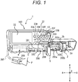
- Fig. 1 is a perspective view showing a liquid medicine administration system 1 including a prefilled syringe 200 and a syringe pump 100 according to one embodiment.
- Fig. 2 is a perspective view showing the prefilled syringe 200 shown in Fig. 1 .
- Fig. 3 is a view showing an information label 300 to be attached to the prefilled syringe 200 shown in Fig. 2 .
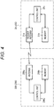
- Fig. 4 is a block diagram showing an RFID tag 206 attached to the prefilled syringe 200 and a reader 31 of the syringe pump 100.
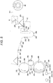
- Fig. 5 is a diagram showing an example of a method for obtaining the prefilled syringe 200 having the information label 300 attached thereto.
- Fig. 1 is a perspective view showing a liquid medicine administration system 1 including a prefilled syringe 200 and a syringe pump 100 according to one embodiment.
- Fig. 2 is a perspective view showing the prefilled syringe
- Fig. 6 is an enlarged front view in which a part of the front view of a main body 3 of the syringe pump 100 shown in Fig. 1 is enlarged.
- Fig. 7 is a sectional view of the prefilled syringe 200 and the syringe pump 100 shown in Fig. 1 . More specifically, Fig. 7 is a sectional view showing a cross section perpendicular to the axial direction of the prefilled syringe 200 in a state where the prefilled syringe 200 is mounted on the syringe pump 100.
- Fig. 8 is a perspective view showing a prefilled syringe 600 according to another embodiment.
- the liquid medicine administration system 1 includes the syringe pump 100 and the prefilled syringe 200 that can be mounted to the syringe pump 100. Each component will be described below.
- the prefilled syringe 200 includes a liquid medicine 201, a barrel 202, a cap 203, a gasket 204, a plunger 205, and an RFID tag 206.
- the liquid medicine 201 is, for example, an anticancer agent, an anesthetic, a chemotherapeutic agent, a blood transfusion, a nutrient, or the like.
- the liquid medicine 201 is contained in the barrel 202.
- the liquid medicine 201 is microinjected into the patient's body as described later.
- the barrel 202 includes a cylindrical body section 202a, a nozzle section 202b, and a flange 202c.
- the body section 202a contains the liquid medicine 201.
- An outer diameter D of the body section 202a is 14 mm to 33 mm.
- the circumferential length of the outer circumferential surface of the body section 202a is 2.0 to 7.0 times the maximum circumferential length Lc of a later-described antenna of the RFID tag 206.
- the nozzle section 202b is provided on the distal end side of the body section 202a.
- a distal end opening 202b1 is provided at a distal end section of the nozzle section 202b.
- the liquid medicine 201 is expelled from the distal end opening 202b1.
- a tube 207 (indicated by a chain double-dashed line in Figs. 1 and 2 ) can be connected to the nozzle section 202b.
- the flange 202c protrudes outward from the proximal end section of the body section 202a in the radial direction B of the body section 202a.
- the cap 203 can seal the distal end opening 202b1 provided at the distal end section of the nozzle section 202b.
- the cap 203 can be attached to the nozzle section 202b, and Fig. 2 shows a state in which the cap 203 is removed from the nozzle section 202b and the distal end opening 202b1 is opened.
- the gasket 204 slides on the inner circumferential surface of the body section 202a.
- the gasket 204 in the present embodiment is a tubular body having a closed distal end and an open proximal end.
- the gasket 204 constitutes a liquid medicine containing section in which the liquid medicine 201 is contained in the barrel 202.
- an amount of the liquid medicine to be contained is 5 ml to 50 ml.
- an amount (ml) of liquid medicine to be contained is associated with the outer diameter D (mm) of the prefilled syringe 200, and is specified in, for example, ISO 11040-6 (Prefilled syringes-Part 6: Plastic barrels for injectables).
- the outer diameter D when a prefilled syringe that can contain 5 ml of liquid medicine is used, the outer diameter D is 14 mm. In addition, when the amount of the liquid medicine that can be contained is 10 ml, the outer diameter D is 17 mm. When the amount of the liquid medicine that can be contained is 20 ml, the outer diameter D is 22 mm. Further, when the amount of the liquid medicine that can be contained is 50 ml, the outer diameter D is 33 mm.
- the plunger 205 can be mounted to the gasket 204.
- the plunger 205 includes a plunger body 205a and a flange 205b.
- the distal end section of the plunger body 205a can be fixed to the gasket 204 while being inserted from the proximal end side of the gasket 204.
- the plunger body 205a and the gasket 204 can be fixed to each other by, for example, thread connection.
- the plunger body 205a is inserted into the body section 202a and is movable in the axial direction A of the body section 202a within the body section 202a.
- the flange 205b protrudes outward from the plunger body 205a in the radial direction B on the proximal end section of the plunger 205.
- the RFID tag 206 is attached to the outer surface of the information label 300 described later. That is, the RFID tag 206 in the present embodiment is attached to the outer circumferential surface of the body section 202a via the information label 300. In another embodiment, the information label 300 may be attached to the body section 202a of the barrel 202 so as to cover the outer surface of the RFID tag 206.
- the RFID tag 206 is not attached to the body section 202a over the entire circumference in the circumferential direction C, but is attached only to a part of the body section 202a in the circumferential direction C.
- the maximum axial length La of the RFID tag 206 along the axial direction A of the body section 202a of the barrel 202 is 8 mm to 25 mm.
- the proximal end of the RFID tag 206 is located distant from the distal end of the flange 202c of the barrel 202 by 15 mm to 40 mm (for example, 24.8 mm) in a distal direction toward the distal end of the body section 202a in the axial direction A.
- the RFID tag 206 is located proximal to the distal end of the gasket 204 in the axial direction A of the body section 202a.
- the RFID tag 206 in the present embodiment is located proximal to the distal end of the gasket 204 of the unused prefilled syringe 200 in the axial direction A of the body section 202a. In other words, the RFID tag 206 in the present embodiment is not located further distal to the distal end of the gasket 204 in the axial direction A of the body section 202a.
- a portion hereinafter referred to as a clamp contact portion 209 clamped by a clamp section 5 of the syringe pump 100 in the outer circumferential surface of the prefilled syringe 200 is located proximal to the portion where the RFID tag 206 is attached.
- the RFID tag 206 can be formed into a rectangle having a circumferential length Lc of 18 mm and an axial length La of 18 mm in a state where the position is fixed with respect to the outer circumferential surface of the body section 202a.
- the RFID tag 206 may be formed into a rectangle having a circumferential length Lc of 25 mm and an axial length La of 25 mm in the same state.
- the RFID tag 206 may also be formed into a rectangle having a circumferential length Lc of 12 mm and an axial length La of 9 mm in the same state.
- the RFID tag 206 has an antenna 206a for communication, a memory 206b, and a control unit 206c.
- the antenna 206a of the RFID tag 206 is structured from an antenna wire wound in a rectangle.
- the area on the body section 202a where the RFID tag 206 can be installed is limited as shown in Fig. 2 , a loop area formed by the antenna wire is easily ensured by winding the antenna wire in a rectangle, as compared with a configuration in which the antenna wire is wound in a circle.
- the RFID tag 206 of the prefilled syringe 200 and the reader 31 of the syringe pump 100 are not aligned with high precision when the prefilled syringe 200 is mounted on a supporting section 4 of the syringe pump 100, the RFID tag 206 can communicate with the reader 31 as shown in Figs. 1 and 7 .
- the antenna 206a of the RFID tag 206 performs communication by wireless communication having a short working distance such as near field communication (NFC).
- NFC near field communication
- the maximum circumferential length Lc of the antenna 206a of the RFID tag 206 along the circumferential direction C of the body section 202a of the barrel 202 is 9 mm to 25 mm.
- the outer perimeter of the antenna 206a can be formed into a rectangle having a circumferential length of 15 mm and an axial length of 15 mm in the abovementioned state.
- the outer perimeter of the antenna 206a may be formed into a rectangle having a circumferential length of 25 mm and an axial length of 25 mm in the abovementioned state.
- the control unit 206c of the RFID tag 206 can read data from the memory 206b and cause the antenna 206a to transmit the data.
- a communicable distance is short (for example, within 35 mm). Therefore, when the RFID tag 206 of the prefilled syringe 200 is distant from the reader antenna 31a of the reader 31 by a predetermined distance or more, the reader antenna 31a of the reader 31 cannot communicate with the RFID tag 206 of the prefilled syringe 200.
- the memory 206b and the control unit 206c of the RFID tag 206 can be constituted by, for example, an integrated circuit (IC chip) including a nonvolatile memory.
- the antenna 206a of the RFID tag 206 receives an electromagnetic wave transmitted from the reader antenna 31a of the reader 31 of the syringe pump 100.
- the operating power of the RFID tag 206 can be obtained from this electromagnetic wave.
- the control unit 206c reads the data in the memory 206b of the RFID tag 206, and sends (transmits) the data to the reader antenna 31a of the reader 31 through the electromagnetic wave using the antenna 206a.
- the reader antenna 31a of the reader 31 receives the electromagnetic wave from the antenna 206a of the RFID tag 206.
- control unit 31c of the syringe pump 100 acquires the data stored in the memory 206b of the RFID tag 206 by extracting the data from the received electromagnetic wave, and stores the data in the storage unit 31b of the syringe pump 100.
- the memory 206b of the RFID tag 206 stores, for example, various kinds of data regarding the prefilled syringe 200, such as the name of the liquid medicine 201, identification data for each prefilled syringe, dimensional data of the barrel 202, and dimensional data of the stroke of the plunger 205.
- the information label 300 is attached to the outer circumferential surface of the body section 202a of the barrel 202.
- Fig. 3 shows the information label 300 which is not yet attached to the outer circumferential surface of the body section 202a.
- the information label 300 is provided with two scales 301 which extend along the axial direction A of the body section 202a when the information label 300 is attached to the outer circumferential surface of the body section 202a (see Fig. 2 ). More specifically, the notches of the two scales 301 in the present embodiment are arranged along the axial direction A of the body section 202a when the information label 300 is attached to the outer circumferential surface of the body section 202a.
- the scales 301 indicate the amount of the liquid medicine 201 in the body section 202a when the information label 300 is attached to the outer circumferential surface of the body section 202a.
- the two scales 301 are symmetrical with respect to the central axis of the body section 202a.
- the RFID tag 206 is attached between the two scales 301 of the information label 300.
- the RFID tag 206 is attached to the outer surface of the information label 300.
- the RFID tag 206 can be attached to the inner surface of the information label 300.
- a part of the RFID tag 206 is located at a position overlapping with a part of the two scales 301 in the longitudinal direction of the information label 300 and displaced in the transverse direction of the information label 300. That is, when the information label 300 is attached to the outer circumferential surface of the body section 202a as shown in Fig. 2 , a part of the RFID tag 206 is located at a position overlapping with a part of the scales 301 in the axial direction A of the body section 202a of the barrel 202 and displaced in the circumferential direction C of the body section 202a of the barrel 202.
- the information label 300 can be provided with an information area 302 in which the name of the medicine or an amount of the liquid medicine is written, in addition to the scales 301.
- a rollshaped mount 401 is pulled out.
- RFID tags 206 are mounted on the mount 401 at regular intervals.
- various kinds of information are written in the RFID tag 206 as indicated by an area R1.
- the RFID tag 206 is removed from the mount 401, and the removed RFID tag 206 is attached to the outer surface of the information label 300.
- the orientation of the information label 300 is properly set on a drum 402.
- the information label 300 is attached to the outer circumferential surface of the body section 202a of the prefilled syringe 200 using a drum 404.
- the syringe pump 100 is used in, for example, an intensive care unit. Further, the syringe pump 100 can be used when a liquid medicine such as an anticancer agent, an anesthetic, a chemotherapeutic agent, a blood transfusion, or a nutrient is microinjected to a patient P over a relatively long time with high accuracy.
- a liquid medicine such as an anticancer agent, an anesthetic, a chemotherapeutic agent, a blood transfusion, or a nutrient is microinjected to a patient P over a relatively long time with high accuracy.
- the syringe pump 100 can be mounted to and removed from a stand or the like, and can be used while being mounted on the stand or the like.
- the syringe pump 100 is fixed such that the axial direction A of the body section 202a of the prefilled syringe 200 mounted on the syringe pump 100 coincides with the horizontal direction.
- the syringe pump 100 includes a syringe plunger driving section 2, a main body 3, a supporting section 4, and a clamp section 5.
- the syringe plunger driving section 2 drives the plunger 205 of the prefilled syringe 200 in the distal direction toward the distal end of the body section 202a.
- the syringe plunger driving section 2 in the present embodiment includes a pressing part 2a and a flange fixing part 2b.
- the pressing part 2a is located proximal to the flange 205b of the plunger 205 of the mounted prefilled syringe 200 in the axial direction A. Then, when the pressing part 2a is moved toward the distal side in the axial direction A, the surface of the flange 205b on the proximal side in the axial direction A can be pressed toward the distal side in the axial direction A. Accordingly, the plunger 205 can be relatively moved to the distal side in the axial direction A with respect to the barrel 202 of the mounted prefilled syringe 200.
- the flange fixing part 2b fixes the flange 205b of the plunger 205 to the pressing part 2a.
- the flange fixing part 2b in the present embodiment is located on the distal side of the pressing part 2a in the axial direction A and is attached to the pressing part 2a. While the prefilled syringe 200 is mounted, the flange 205b of the plunger 205 is located between the pressing part 2a and the flange fixing part 2b.
- the plunger 205 is movable in the axial direction A with the movement of the syringe plunger driving section 2 in the axial direction A.
- Fig. 6 is an enlarged front view in which a part of the front view of the main body 3 of the syringe pump 100 is enlarged. More specifically, Fig. 6 is an enlarged view of a position of the later-described supporting section 4 that receives the prefilled syringe 200 in the main body 3. Note that, for convenience of description, Fig. 6 shows the barrel 202 of the prefilled syringe 200 which is appropriately received by the supporting section 4 with the flange 202c being engaged with a flange receiving groove 7 (see Fig. 1 ) of the main body 3.
- the main body 3 is provided with the reader 31 including the reader antenna 31a that receives a data set stored in the memory of the RFID tag 206 of the prefilled syringe 200, and a control unit 13 (see Fig. 1 ) that controls the syringe plunger driving section 2.
- the reader 31 and the control unit 13 in the present embodiment are arranged inside the main body 3.
- the control unit 13 of the syringe pump 100 and the control unit 31c described above can be provided as separate components. Further, the control unit 31c and the control unit 13 may be integrated as the same component.
- the reader antenna 31a of the reader 31 is structured from a reader antenna wire. As shown in Fig.
- the outer perimeter of the reader antenna 31a structured from the reader antenna wire is rectangular.
- a part of the reader antenna 31a of the reader 31 is displaced from a later-described first region 3a1 that faces the later-described clamp section 5 (see Fig. 1 ) of the syringe pump 100 in the axial direction A in a front view (same as the front view of the main body 3 in Fig. 6 ) of the supporting section 4 of the syringe pump 100.
- the main body 3 has the first region 3a1 that faces the clamp section 5, and a second region 3a2 that is adjacent to the first region 3a1 on the side opposite to the syringe plunger driving section 2 in the axial direction A of the body section 202a. Then, at least a part of the reader antenna 31a of the reader 31 is located in the second region 3a2. Further, in the present embodiment, in the front view of the supporting section 4 (the same as the front view of the main body 3 in the present embodiment), the centerline lca of the reader antenna 31a, which is perpendicular to the axial direction A of the body section 202a of the barrel 202, is located in the second region 3a2.
- the centerline lca of the reader antenna 31a overlaps with the antenna 206a of the RFID tag 206 in the front view of the supporting section 4.
- the centerline lca of the reader antenna 31a is a line passing through the centers of two sides along the axial direction A of the body section 202a of the barrel 202 among the sides defining the perimeter of the reader antenna 31a.
- the centerline lca of the reader antenna 31a is a line perpendicular to the axial direction A of the body section 202a of the prefilled syringe 200 and bisecting the loop area of the reader antenna 31a. If the perimeter of the reader antenna is not rectangular, a line that is perpendicular to the axial direction of the body section of the prefilled syringe and that bisects the loop area of the reader antenna may be used as the centerline.
- the reader antenna 31a of the reader 31 can emit an electromagnetic wave in a state where the prefilled syringe 200 is received by the later-described supporting section 4.
- the RFID tag 206 attached to the prefilled syringe 200 transmits data in response to the electromagnetic wave.
- the reader antenna 31a of the reader 31 can receive the data.
- the main body 3 in the present embodiment includes a display unit 32 and an operation panel 33.
- the display unit 32 is an image display device capable of color display.
- the display unit 32 can be composed of, for example, a color liquid crystal display device.
- the display unit 32 can display not only information in Japanese but also information in a plurality of foreign languages as needed.
- the display unit 32 in the present embodiment is provided above the later-described supporting section 4 in the front surface of the syringe pump 100.
- the display unit 32 may include an input device such as a touch sensor and may receive an input from the user.
- the operation panel 33 is disposed above the supporting section 4 and on the right of the display unit 32 in the front surface of the syringe pump 100.
- the operation panel 33 includes a power switch 33A, an operation indicator 33H, and operation switches.
- Fig. 1 shows a fast delivery switch 33B, a start switch 33C, a stop switch 33D, a display changeover switch 33E, a return/mute switch 33F, and a confirmation switch 33G as an example of the operation switches.
- the main body 3 in the present embodiment includes inside various wires for electrically connecting the components of the syringe pump 100, various mechanisms for executing commands from the control unit, a communication unit capable of wireless or wired communication with external devices other than the RFID tag 206, a storage unit that stores various kinds of data and various programs necessary for the operation of the syringe pump 100, and the like.
- the supporting section 4 in the present embodiment is formed on the front surface of the main body 3. Further, the supporting section 4 in the present embodiment supports the outer circumferential surface of the body section 202a of the prefilled syringe 200 in a direction perpendicular to the central axis of the body section 202a. As shown in Fig. 7 , the supporting section 4 in the present embodiment is constituted by a concave curved surface having a substantially semicircular cross section in order to receive the outer circumferential surface of the body section 202a. Further, the supporting section 4 in the present embodiment can receive a plurality of types of body sections 202a having different sizes such as outer diameters.
- the clamp section 5 faces the supporting section 4 formed on the main body 3 and clamps the body section 202a of the prefilled syringe 200 with the supporting section 4.
- the clamp contact portion 209 which is a portion of the outer circumferential surface of the body section 202a where the clamp section 5 clamps the prefilled syringe 200 is different from the portion where the RFID tag 206 is attached, and is located proximal to the portion where the RFID tag 206 is attached.
- the clamp section 5 is supported by a base 6 so as to be movable in the longitudinal direction of the base 6 (direction parallel to the central axis O2). Therefore, the distance between the clamp section 5 and the supporting section 4 provided on the front surface of the main body 3 can be changed by moving the clamp section 5 in the longitudinal direction of the base 6. This makes it possible to move the clamp section 5 between a clamping position and a non-clamping position.
- the clamping position of the clamp section 5 indicates a position where the body section 202a of the prefilled syringe 200 is clamped between the clamp section 5 and the supporting section 4 as shown in Fig. 7 . Further, the non-clamping position of the clamp section 5 indicates a position where the clamp section 5 is moved further away from the supporting section 4 with respect to the clamp position so as not to clamp the body section 202a with the supporting section 4.
- the clamp section 5 is constantly biased by a biasing member such as a spring member in a direction approaching the supporting section 4 in the longitudinal direction of the base 6. Therefore, when the clamp section 5 is moved from the clamping position to the non-clamping position, the clamp section 5 is moved against the biasing force of the biasing member.
- a biasing member such as a spring member
- the clamp section 5 is supported by the base 6 so as to be movable not only in the longitudinal direction of the base 6 but also in the circumferential direction around the central axis O2 of the base 6.
- the position of the base 6 in the longitudinal direction can be fixed so that the clamp section 5 does not move in the longitudinal direction of the base 6.
- the clamp section 5 is rotatable in the circumferential direction around the central axis O2 of the base 6 between a position facing the supporting section 4 and a position not facing the supporting section 4. This rotation operation is disabled when the clamp section 5 is at the clamping position, and is enabled when the clamp section 5 is at the non-clamping position.
- the clamp section 5 can be set to have an angle by which the clamp section 5 does not face the supporting section 4, and in this state, the prefilled syringe 200 can be easily placed on the receiving surface of the supporting section 4.
- the prefilled syringe 200 operates as follows in the mounted state (see Fig. 1 ) mounted on the syringe pump 100.
- the plunger 205 is pressed toward the distal side in the axial direction A by the syringe pump 100.
- the gasket 204 connected to the plunger 205 slides toward the distal side in the axial direction A within the body section 202a of the barrel 202.
- the liquid medicine 201 in the body section 202a is compressed.
- the liquid medicine 201 is expelled through the nozzle section 202b of the body section 202a by the compressive force.
- the tube 207 (see Fig. 1 ) is connected to the distal end opening 202b1 of the nozzle section 202b of the prefilled syringe 200.
- an indwelling needle 208 to be indwelled in the patient P is connected to the distal end of the tube 207. Therefore, the liquid medicine 201 in the body section 202a can be delivered into the body of the patient P through the tube 207 and the indwelling needle 208.
- Fig. 8 shows a prefilled syringe 600 according to another embodiment.
- the longitudinal length ratio of an information label 400 in Fig. 8 is smaller than the longitudinal length ratio of the information label 300 in Fig. 2 .
- the longitudinal length ratio means the ratio of the total length of the information label in the axial direction A to the total length of the barrel in the axial direction A of the body section.
- the RFID tag 206 in Fig. 8 has a configuration same as the configuration shown in Fig. 2 . However, the distance (for example, 24.8 mm) between the flange 202c and the RFID tag 206 in the axial direction A in Fig.
- the clamp contact portion 209 of the syringe pump 100 is also located proximal to the portion where the RFID tag 206 is attached in Fig. 8 .
- the other configuration of the prefilled syringe 600 is the same as that of the prefilled syringe 200, and thus the description thereof will be omitted.
- the outer diameter D of the body section 202a of the barrel 202 is 14 mm to 33 mm.
- the maximum circumferential length Lc of the antenna of the RFID tag 206 along the circumferential direction C of the body section 202a of the barrel 202 is 9 mm to 25 mm.
- the circumferential length of the outer circumferential surface of the body section 202a is 2.0 to 7.0 times the maximum circumferential length of the antenna of the RFID tag 206.
- the RFID tag 206 of the prefilled syringe 200 and the reader of the syringe pump 100 are not aligned when the cylindrical prefilled syringe 200 or 600 is mounted on the supporting section 4 of the syringe pump 100, the RFID tag 206 can communicate with the reader 31. Further, since the positional alignment of the prefilled syringe 200 or 600 is unnecessary, it is possible to prevent the RFID tag 206 fixed to the outer circumferential surface of the prefilled syringe 200 or 600 from being damaged because of the sliding movement between the RFID tag 206 of the prefilled syringe 200 or 600 and the supporting section 4 of the syringe pump 100.
- the attached RFID tag may be deformed and detached, because the outer circumferential surface of the prefilled syringe is curved.
- detachment of the RFID tag 206 attached to the outer circumferential surface of the prefilled syringe 200 or 600 can be prevented.
- the maximum axial length La of the RFID tag 206 along the axial direction of the body section 202a of the barrel 202 is 8 mm to 25 mm. Due to the maximum axial length La of the RFID tag 206 being set to 8 mm or more, the RFID tag 206 can more reliably communicate with the reader of the syringe pump 100 when the cylindrical prefilled syringe 200 or 600 is mounted on the supporting section 4 of the syringe pump 100.
- the maximum axial length La of the RFID tag 206 being set to 25 mm or less, it is possible to prevent the scale 301 from being difficult to see by the RFID tag 206, and to prevent the RFID tag 206 from deteriorating visibility of the liquid medicine 201 contained in the body section 202a.
- the barrel 202 has the flange 202c protruding from the proximal end section of the body section 202a, the body section 202a has, near the flange 202c, the clamp contact portion 209 where the clamp section 5 of the syringe pump 100 that drives the plunger 205 contacts, and the RFID tag 206 is located distal to the clamp contact portion 209 in the axial direction A of the body section 202a. This prevents the clamp section 5 of the syringe pump 100 from contacting the RFID tag 206, thereby being capable of preventing the RFID tag 206 from being damaged.
- the distance between the proximal end of the RFID tag 206 and the distal end of the flange 202c of the barrel 202 in the axial direction of the body section 202a is 15 mm to 40 mm. Due to the configuration in which the distance between the proximal end of the RFID tag 206 and the distal end of the flange 202c of the barrel 202 is set to 15 mm or more in the axial direction of the body section 202a, the contact between the clamp section 5 of the syringe pump 100 and the RFID tag 206 can be prevented to prevent damage of the RFID tag 206.
- the distance between the proximal end of the RFID tag 206 and the distal end of the flange 202c of the barrel 202 is set to 40 mm or less in the axial direction of the body section 202a, it is possible to prevent the scale 301 from being difficult to see and to ensure visibility of the liquid medicine 201 contained in the body section 202a.
- the RFID tag 206 is located proximal to the distal end of the gasket 204 in the axial direction A of the body section 202a. This configuration can prevent the scale 301 from being difficult to see, and can ensure visibility of the liquid medicine 201 contained in the body section 202a.
- the prefilled syringe 200 further includes the information label 300 attached to the body section 202a of the barrel 202.
- the RFID tag 206 can be attached to the inner surface or the outer surface of the information label 300.
- the prefilled syringe 200 may be configured such that the information label 300 is attached to the body section 202a of the barrel 202 so as to cover the outer surface of the RFID tag 206. This can prevent the RFID tag 206 fixed to the outer circumferential surface of the body section 202a from being detached.
- the information label 300 has the scale 301 indicating an amount of the liquid medicine 201 in the body section 202a, the scale 301 being provided along the axial direction A of the body section 202a of the barrel 202, and at least a part of the RFID tag 206 is located at a position overlapping with at least a part of the scale 301 in the axial direction A of the body section 202a of the barrel 202 and displaced in the circumferential direction C of the body section 202a of the barrel 202.
- a plurality of scales 301 is provided, and the RFID tag 206 is located between at least two scales 301.
- At least two scales 301 are symmetrical with respect to the central axis of the body section 202a of the barrel 202. With this configuration, at least one scale 301 can be exposed and visually recognized more reliably.
- the syringe pump 100 has the clamp section 5 that faces the supporting section 4 and clamps the body section 202a of the prefilled syringe 200 or 600 with the supporting section 4, and when the clamp section 5 clamps the prefilled syringe 200 or 600 between the supporting section 4 and the clamp section 5, the clamp contact portion 209 which is a region clamped by the clamp section 5 in the outer circumferential surface of the body section 202a is different from a region where the RFID tag 206 is attached. This prevents the clamp section 5 of the syringe pump 100 from contacting the RFID tag 206, thereby being capable of preventing the RFID tag 206 from being damaged.
- the barrel 202 has the flange 202c that protrudes from the proximal end section of the body section 202a, a distance between the proximal end of the RFID tag 206 and the distal end of the flange 202c of the barrel 202 is 15 mm to 40 mm in the axial direction of the body section 202a, and the clamp section 5 comes in contact with a vicinity of the flange 202c of the body section 202a, and clamps the prefilled syringe 200 or 600 with the supporting section 4.
- the distance between the proximal end of the RFID tag 206 and the distal end of the flange 202c of the barrel 202 is set to 15 mm or more in the axial direction of the body section 202a, and the clamp section 5 of the syringe pump 100 comes in contact with the clamp contact portion 209 which is the vicinity of the flange 202c of the body section 202a, the contact between the clamp section 5 and the RFID tag 206 can be prevented to prevent damage of the RFID tag 206.
- the distance between the proximal end of the RFID tag 206 and the distal end of the flange 202c of the barrel 202 is set to 40 mm or less in the axial direction of the body section 202a, it is possible to prevent the scale 301 from being difficult to see and to ensure visibility of the liquid medicine 201 contained in the body section 202a.
- the main body 3 of the syringe pump 100 has the first region 3a1 facing the clamp section 5 and the second region 3a2 that is adjacent to the first region 3a1 and is located on a side opposite to the syringe plunger driving section 2 in the axial direction A of the body section 202a
- the reader 31 includes the reader antenna 31a that communicates with the antenna 206a of the RFID tag 206 and that is structured from a reader antenna wire, and at least a part of the reader antenna 31a is located in the second region 3a2. That is, at least a part of the reader antenna 31a is arranged in the second region 3a2, which is not the first region 3a1 facing the clamp section 5.
- the reader antenna 31a can reliably read the data set of the RFID tag 206.
- the prefilled syringe 200 or 600 is mounted to the syringe pump 100 such that at least a part of the RFID tag 206 faces the second region 3a2.
- the centerline lca of the reader antenna 31a perpendicular to the axial direction of the body section 202a of the barrel 202 is located in the second region 3a2 in a front view of the supporting section 4, and the centerline lca of the reader antenna 31a overlaps with the antenna of the RFID tag 206 in the front view of the supporting section 4.
- the position of the centerline lca of the reader antenna 31a substantially coincides with the position where the magnetic flux density of the magnetic flux generated by the reader antenna 31a is the highest. Therefore, due to the configuration in which the centerline lca of the reader antenna 31a overlaps with the antenna of the RFID tag 206, the reader 31 can more reliably read the data set of the RFID tag 206.
- the syringe pump 100 includes the clamp section 5 that faces the supporting section 4 and clamps the body section 202a of the prefilled syringe 200 with the supporting section 4, the main body 3 of the syringe pump 100 has the first region 3a1 facing the clamp section 5 of the body section 202a and the second region 3a2 that is adjacent to the first region 3a1 and is located on a side opposite to the syringe plunger driving section 2 in the axial direction A of the body section 202a, the reader 31 includes the reader antenna 31a that communicates with the antenna of the RFID tag 206 and that is structured from a reader antenna wire, and at least a part of the reader antenna 31a is located in the second region 3a2.
- the reader antenna 31a is arranged in the second region 3a2, which is not the first region 3a1 facing the clamp section 5, so that the reader antenna 31a can read the data set of the RFID tag 206. Further, when the prefilled syringe 200 is clamped by the supporting section 4 and the clamp section 5, the RFID tag 206 can be prevented from being damaged due to contact with the clamp section 5. Note that the prefilled syringe 200 or 600 is mounted to the syringe pump 100 such that at least a part of the RFID tag 206 faces the second region 3a2.
- the centerline lca of the reader antenna 31a which is perpendicular to the body section 202a of the barrel 202, is located in the second region 3a2 in a front view of the supporting section 4. This allows the reader 31 to reliably read the data of the RFID tag 206 of the syringe pump 100.
- prefilled syringes 1 to 6 having different outer diameters of body sections of barrels were prepared.
- the outer diameters of the body sections of the barrels of the prefilled syringes 1 to 6 were 11 mm, 14 mm, 17 mm, 22 mm, 33 mm, and 35.5 mm, respectively.
- RFID tags 1 to 6 were attached to the outer circumferential surfaces of the body sections of the barrels of the prefilled syringes 1 to 6, and then, whether the RFID tags 1 to 6 were detached or not was checked.
- the shape of the tag body including an antenna, a memory, and a control unit and the outer perimeter of an antenna wire are rectangular.
- the shape of a tag body of the RFID tag 6 is a circle with an outer diameter of 28 mm
- the outer perimeter of an antenna wire is a circle with an outer diameter of 25 mm.
- Table 1 shows the dimensions of the tag bodies of the RFID tags 1 to 6 and the dimensions of the antennas.
- Table 1 also shows values (indicated as "syringe-tag circumferential length ratios" in Table 1) each obtained by dividing the circumferential length of the outer circumferential surface of the body section of the barrel of prefilled syringe by the maximum circumferential length of the antenna of the RFID tag.
- the RFID tags 1 to 6 were attached to the outer circumferential surfaces of the body sections of the prefilled syringes 1 to 6, respectively, and then, it was checked whether the RFID tags 1 to 6 were detached.
- "O” in Table 1 shows the case where the RFID tag was not detached.
- "X" indicates that the RFID tag could not be attached due to its large size, or that the RFID tag was attached and then detached, in other words, the RFID tag could not be properly attached to the prefilled syringe.
- the RFID tags 1 to 6 were attached to the outer circumferential surfaces of the body sections of the barrels of the prefilled syringes 1 to 6, and each of the prefilled syringes 1 to 6 was mounted on the syringe pump 100 shown in Fig. 1 .
- the prefilled syringes 1 to 6 were mounted such that the attached RFID tags 1 to 6 were at positions farthest from the reader 31 of the syringe pump 100, that is, the RFID tag 206 faced the front side in Fig. 1 . In such a state, it was checked multiple times whether the reader 31 of the syringe pump 100 could read the data of the RFID tags 1 to 6. "Excellent" in Table 1 indicates that the RFID tag data could be read in all cases.
- the outer diameter of the body section of the barrel is 14 mm to 33 mm
- the maximum circumferential length Lc of the antenna of the RFID tag along the circumferential direction of the body section a of the barrel is 9 mm to 25 mm
- the circumferential length of the outer circumferential surface of the body section is set to be 2.0 to 7.0 times the maximum circumferential length of the antenna of the RFID tag 206
Landscapes
- Health & Medical Sciences (AREA)
- Vascular Medicine (AREA)
- Engineering & Computer Science (AREA)
- Anesthesiology (AREA)
- Biomedical Technology (AREA)
- Heart & Thoracic Surgery (AREA)
- Hematology (AREA)
- Life Sciences & Earth Sciences (AREA)
- Animal Behavior & Ethology (AREA)
- General Health & Medical Sciences (AREA)
- Public Health (AREA)
- Veterinary Medicine (AREA)
- Infusion, Injection, And Reservoir Apparatuses (AREA)
Abstract
Description
- The present disclosure relates to a prefilled syringe, a liquid medicine administration system, and a syringe pump.
- When a medicine such as an intravenous anesthetic is delivered into the patient's body in a medical setting such as an operating room or an intensive care unit, it is necessary to deliver the medicine over a long time while adjusting a flow rate (hereinafter also simply referred to as a "liquid delivery amount") of the medicine to be delivered according to a technique to be applied, patient's condition, and the like. As a device for accurately delivering a medicine over a long period of time with a set liquid delivery amount, a liquid medicine administration device, such as a syringe pump, capable of delivering a liquid medicine containing a medicine using a prefilled syringe that contains the liquid medicine in a barrel has been known, for example.
- Patent Literature 1 discloses a liquid medicine injection device as a liquid medicine administration device of this type. Patent Literature 1 also discloses a syringe which is to be mounted on the liquid medicine injection device and which has a radio frequency identification (RFID) tag attached thereto, the RFID tag having various kinds of data recorded thereon. Further, the liquid medicine injection device disclosed in Patent Literature 1 has an RFID module including a reader that acquires various kinds of recorded data from the RFID tag of the syringe.
- Patent Literature 1:
JP 2015-217176 A - When the liquid medicine injection device disclosed in Patent Literature 1 is used, the syringe is mounted on a base part of the liquid medicine injection device in a medial setting. When the syringe is mounted, it is necessary to bring the RFID tag close to the reader of the liquid medicine injection device so that the reader of the liquid medicine injection device can acquire the data of the RFID tag of the syringe. Therefore, it is necessary to mount the cylindrical syringe on the base part of the liquid medicine injection device while the RFID tag of the syringe is aligned with the reader of the liquid medicine injection device. This work is complicated for a medical staff. Further, when the positional alignment described above is performed by rotating the syringe about the axis thereof with the syringe being mounted on the base part, the RFID tag may be damaged due to a sliding movement between the RFID tag fixed on the outer circumferential surface of the syringe and the base part of the liquid medicine injection device.
- Further, when the RFID tag is attached to the outer circumferential surface of the syringe, the attached RFID tag may be deformed, because the outer circumferential surface of the syringe is curved. Due to the deformation, the RFID tag may be detached.
- An object of the present disclosure is to provide a prefilled syringe including an RFID tag from which data is easily acquired by a syringe pump and which is less likely to be detached, and a liquid medicine administration system. Another object of the present disclosure is to provide a syringe pump adapted to the prefilled syringe.
- A prefilled syringe according to a first aspect of the present invention includes: a liquid medicine; a barrel including a body section that is cylindrical and that contains the liquid medicine, and a nozzle section that is provided on a distal end side of the body section and that discharges the liquid medicine; a cap that seals a distal end opening provided on a distal end section of the nozzle section; a gasket that slides on an inner circumferential surface of the body section; a plunger mountable to the gasket; and an RFID tag that has a fixed location with respect to an outer circumferential surface of the body section and has an antenna for communication and a memory, the antenna being structured from an antenna wire that is wound in a rectangle, wherein an outer diameter of the body section of the barrel is 14 mm to 33 mm, a maximum circumferential length of the antenna of the RFID tag along a circumferential direction of the body section of the barrel is 9 mm to 25 mm, and a circumferential length of the outer circumferential surface of the body section of the barrel is 2.0 to 7.0 times the maximum circumferential length of the antenna of the RFID tag.
- As one embodiment of the present invention, a maximum axial length of the RFID tag along an axial direction of the body section of the barrel is 8 mm to 25 mm.
- As one embodiment of the present invention, the barrel has a flange that protrudes from a proximal end section of the body section, the body section has, near the flange, a clamp contact portion where a clamp section of a syringe pump that drives the plunger contacts, and the RFID tag is disposed distal to the clamp contact portion in the axial direction of the body section.
- As one embodiment of the present invention, a distance between a proximal end of the RFID tag and a distal end of the flange of the barrel is 15 mm to 40 mm in the axial direction of the body section.
- As one embodiment of the present invention, the RFID tag is located proximal to the distal end of the gasket in the axial direction of the body section.
- The prefilled syringe as one embodiment of the present invention further includes an information label attached to the body section of the barrel, wherein the RFID tag is attached on an inner surface or an outer surface of the information label.
- The prefilled syringe as one embodiment of the present invention further includes an information label attached to the body section of the barrel so as to cover an outer surface of the RFID tag.
- As one embodiment of the present invention, the information label has a scale indicating an amount of the liquid medicine in the body section, the scale being provided along an axial direction of the body section of the barrel, and at least a part of the RFID tag is located at a position overlapping with at least a part of the scale in the axial direction of the body section of the barrel and displaced in the circumferential direction of the body section of the barrel.
- As one embodiment of the present invention, the scale includes a plurality of scales, and the RFID tag is disposed between at least two of the scales.
- As one embodiment of the present invention, the at least two scales are symmetrical with respect to a central axis of the body section of the barrel.
- A liquid medicine administration system as a second aspect of the present invention includes a syringe pump, and a prefilled syringe mounted on the syringe pump, the prefilled syringe including a liquid medicine, a barrel including a body section that is cylindrical and that contains the liquid medicine, and a nozzle section that is provided on a distal end side of the body section and that discharges the liquid medicine, a cap that seals a distal end opening provided on a distal end section of the nozzle section, a gasket that slides on an inner circumferential surface of the body section, a plunger mountable to the gasket, and an RFID tag that has a fixed location with respect to an outer circumferential surface of the body section and has an antenna for communication and a memory, the antenna being structured from an antenna wire that is wound in a rectangle, the syringe pump including a syringe plunger driving section that drives the plunger of the prefilled syringe in a distal direction toward the distal end of the body section, a main body provided with a reader and a control unit that controls the syringe plunger driving section, the reader reading a data set stored in the memory of the RFID tag of the prefilled syringe, a supporting section that supports the outer circumferential surface of the body section of the prefilled syringe in a direction perpendicular to an axis of the body section, and a clamp section that faces the supporting section and clamps the body section with the supporting section, wherein an outer diameter of the body section of the barrel is 14 mm to 33 mm, a maximum circumferential length of the antenna of the RFID tag along a circumferential direction of the body section of the barrel is 9 mm to 25 mm, and a circumferential length of the outer circumferential surface of the body section of the barrel is 2.0 to 7.0 times the maximum circumferential length of the antenna of the RFID tag.
- As one embodiment of the present invention, when the clamp section clamps the prefilled syringe between the supporting section and the clamp section, a region clamped by the clamp section in the outer circumferential surface of the body section is different from a region where the RFID tag is attached.
- As one embodiment of the present invention, the barrel has a flange that protrudes from a proximal end section of the body section, a distance between a proximal end of the RFID tag and a distal end of the flange of the barrel is 15 mm to 40 mm in the axial direction of the body section, and the clamp section comes in contact with a vicinity of the flange of the body section, and clamps the prefilled syringe with the supporting section.
- As one embodiment of the present invention, the main body of the syringe pump has a first region facing the clamp section and a second region that is adjacent to the first region and is located on a side opposite to the syringe plunger driving section in the axial direction of the body section, the reader includes a reader antenna that communicates with the antenna of the RFID tag and that is structured from a reader antenna wire, and at least a part of the reader antenna is located in the second region.
- As one embodiment of the present invention, a centerline of the reader antenna perpendicular to the axial direction of the body section of the barrel is located in the second region in a front view of the supporting section, and the centerline of the reader antenna overlaps with the antenna of the RFID tag in the front view of the supporting section.
- A liquid medicine administration system according to a third aspect of the present invention is a syringe pump to which a prefilled syringe is mounted, the prefilled syringe including a liquid medicine, a barrel including a body section that is cylindrical and that contains the liquid medicine, and a nozzle section that is provided on a distal end side of the body section and that discharges the liquid medicine, a cap that seals a distal end opening provided on a distal end section of the nozzle section, a gasket that slides on an inner circumferential surface of the body section, a plunger mountable to the gasket, and an RFID tag that has a fixed location with respect to an outer circumferential surface of the body section and has an antenna for communication and a memory, the antenna being structured from an antenna wire that is wound in a rectangle, the syringe pump including: a syringe plunger driving section that drives the plunger of the prefilled syringe in a distal direction toward the distal end of the body section; a main body provided with a reader and a control unit that controls the syringe plunger driving section, the reader reading a data set stored in the memory of the RFID tag of the prefilled syringe; a supporting section that supports the outer circumferential surface of the body section of the prefilled syringe in a direction perpendicular to an axis of the body section; and a clamp section that faces the supporting section and clamps the body section of the prefilled syringe with the supporting section, wherein the main body of the syringe pump has a first region facing the clamp section and a second region that is adjacent to the first region and is located on a side opposite to the syringe plunger driving section in an axial direction of the body section, the reader includes a reader antenna that communicates with the antenna of the RFID tag and that is structured from a reader antenna wire, and at least a part of the reader antenna is located in the second region.
- As one embodiment of the present invention, a centerline of the reader antenna perpendicular to the axial direction of the body section of the barrel is located in the second region in a front view of the supporting section.
- The present disclosure can provide a prefilled syringe including an RFID tag from which data is easily acquired by a syringe pump and which is less likely to be detached, and a liquid medicine administration system. Moreover, the present disclosure can provide a syringe pump adapted to the prefilled syringe.
-
-
Fig. 1 is a perspective view showing a liquid medicine administration system including a prefilled syringe and a syringe pump as one embodiment. -
Fig. 2 is a perspective view showing the prefilled syringe shown inFig. 1 . -
Fig. 3 is a view showing an information label to be attached to the prefilled syringe shown inFig. 2 . -
Fig. 4 is a block diagram showing an RFID tag attached to the prefilled syringe and a reader of the syringe pump. -
Fig. 5 is a diagram showing an example of a method for obtaining a prefilled syringe having an information label attached thereto. -
Fig. 6 is an enlarged front view in which a part of the front view of a main body of the syringe pump shown inFig. 1 is enlarged. -
Fig. 7 is a sectional view of the prefilled syringe and the syringe pump shown inFig. 1 . -
Fig. 8 is a perspective view showing a prefilled syringe according to another embodiment. - Hereinafter, embodiments of a prefilled syringe, a liquid medicine administration system, and a syringe pump according to the present disclosure will be described with reference to
Figs. 1 to 8 . In the drawings, same members and parts are denoted by the same reference numerals. -
Fig. 1 is a perspective view showing a liquid medicine administration system 1 including a prefilledsyringe 200 and asyringe pump 100 according to one embodiment.Fig. 2 is a perspective view showing theprefilled syringe 200 shown inFig. 1 .Fig. 3 is a view showing aninformation label 300 to be attached to the prefilledsyringe 200 shown inFig. 2 .Fig. 4 is a block diagram showing anRFID tag 206 attached to theprefilled syringe 200 and areader 31 of thesyringe pump 100.Fig. 5 is a diagram showing an example of a method for obtaining the prefilledsyringe 200 having theinformation label 300 attached thereto.Fig. 6 is an enlarged front view in which a part of the front view of amain body 3 of thesyringe pump 100 shown inFig. 1 is enlarged.Fig. 7 is a sectional view of the prefilledsyringe 200 and thesyringe pump 100 shown inFig. 1 . More specifically,Fig. 7 is a sectional view showing a cross section perpendicular to the axial direction of the prefilledsyringe 200 in a state where the prefilledsyringe 200 is mounted on thesyringe pump 100.Fig. 8 is a perspective view showing aprefilled syringe 600 according to another embodiment. - As shown in
Fig. 1 , the liquid medicine administration system 1 according to the present embodiment includes thesyringe pump 100 and the prefilledsyringe 200 that can be mounted to thesyringe pump 100. Each component will be described below. - First, the
prefilled syringe 200 will be described in detail. As shown inFig. 2 , theprefilled syringe 200 includes aliquid medicine 201, abarrel 202, acap 203, agasket 204, aplunger 205, and anRFID tag 206. - The
liquid medicine 201 is, for example, an anticancer agent, an anesthetic, a chemotherapeutic agent, a blood transfusion, a nutrient, or the like. Theliquid medicine 201 is contained in thebarrel 202. Theliquid medicine 201 is microinjected into the patient's body as described later. - The
barrel 202 includes acylindrical body section 202a, anozzle section 202b, and aflange 202c. - The
body section 202a contains theliquid medicine 201. An outer diameter D of thebody section 202a is 14 mm to 33 mm. Further, the circumferential length of the outer circumferential surface of thebody section 202a is 2.0 to 7.0 times the maximum circumferential length Lc of a later-described antenna of theRFID tag 206. - The
nozzle section 202b is provided on the distal end side of thebody section 202a. A distal end opening 202b1 is provided at a distal end section of thenozzle section 202b. Theliquid medicine 201 is expelled from the distal end opening 202b1. A tube 207 (indicated by a chain double-dashed line inFigs. 1 and2 ) can be connected to thenozzle section 202b. - The
flange 202c protrudes outward from the proximal end section of thebody section 202a in the radial direction B of thebody section 202a. - The
cap 203 can seal the distal end opening 202b1 provided at the distal end section of thenozzle section 202b. Thecap 203 can be attached to thenozzle section 202b, andFig. 2 shows a state in which thecap 203 is removed from thenozzle section 202b and the distal end opening 202b1 is opened. - The
gasket 204 slides on the inner circumferential surface of thebody section 202a. Thegasket 204 in the present embodiment is a tubular body having a closed distal end and an open proximal end. Thegasket 204 constitutes a liquid medicine containing section in which theliquid medicine 201 is contained in thebarrel 202. In the present embodiment, an amount of the liquid medicine to be contained is 5 ml to 50 ml. Note that, in general, an amount (ml) of liquid medicine to be contained is associated with the outer diameter D (mm) of theprefilled syringe 200, and is specified in, for example, ISO 11040-6 (Prefilled syringes-Part 6: Plastic barrels for injectables). In the present embodiment, when a prefilled syringe that can contain 5 ml of liquid medicine is used, the outer diameter D is 14 mm. In addition, when the amount of the liquid medicine that can be contained is 10 ml, the outer diameter D is 17 mm. When the amount of the liquid medicine that can be contained is 20 ml, the outer diameter D is 22 mm. Further, when the amount of the liquid medicine that can be contained is 50 ml, the outer diameter D is 33 mm. - The
plunger 205 can be mounted to thegasket 204. Theplunger 205 includes aplunger body 205a and aflange 205b. In the present embodiment, the distal end section of theplunger body 205a can be fixed to thegasket 204 while being inserted from the proximal end side of thegasket 204. Theplunger body 205a and thegasket 204 can be fixed to each other by, for example, thread connection. Theplunger body 205a is inserted into thebody section 202a and is movable in the axial direction A of thebody section 202a within thebody section 202a. Theflange 205b protrudes outward from theplunger body 205a in the radial direction B on the proximal end section of theplunger 205. - In the present embodiment, the
RFID tag 206 is attached to the outer surface of theinformation label 300 described later. That is, theRFID tag 206 in the present embodiment is attached to the outer circumferential surface of thebody section 202a via theinformation label 300. In another embodiment, theinformation label 300 may be attached to thebody section 202a of thebarrel 202 so as to cover the outer surface of theRFID tag 206. - The
RFID tag 206 is not attached to thebody section 202a over the entire circumference in the circumferential direction C, but is attached only to a part of thebody section 202a in the circumferential direction C. - In the present embodiment, the maximum axial length La of the
RFID tag 206 along the axial direction A of thebody section 202a of thebarrel 202 is 8 mm to 25 mm. In the present embodiment, the proximal end of theRFID tag 206 is located distant from the distal end of theflange 202c of thebarrel 202 by 15 mm to 40 mm (for example, 24.8 mm) in a distal direction toward the distal end of thebody section 202a in the axial direction A. In the present embodiment, theRFID tag 206 is located proximal to the distal end of thegasket 204 in the axial direction A of thebody section 202a. Specifically, theRFID tag 206 in the present embodiment is located proximal to the distal end of thegasket 204 of theunused prefilled syringe 200 in the axial direction A of thebody section 202a. In other words, theRFID tag 206 in the present embodiment is not located further distal to the distal end of thegasket 204 in the axial direction A of thebody section 202a. As shown inFig. 1 , in the present embodiment, a portion (hereinafter referred to as a clamp contact portion 209) clamped by aclamp section 5 of thesyringe pump 100 in the outer circumferential surface of theprefilled syringe 200 is located proximal to the portion where theRFID tag 206 is attached. - For example, the
RFID tag 206 can be formed into a rectangle having a circumferential length Lc of 18 mm and an axial length La of 18 mm in a state where the position is fixed with respect to the outer circumferential surface of thebody section 202a. Alternatively, theRFID tag 206 may be formed into a rectangle having a circumferential length Lc of 25 mm and an axial length La of 25 mm in the same state. TheRFID tag 206 may also be formed into a rectangle having a circumferential length Lc of 12 mm and an axial length La of 9 mm in the same state. - As shown in
Figs. 3 and4 , theRFID tag 206 has anantenna 206a for communication, amemory 206b, and acontrol unit 206c. - As shown in
Fig. 3 , theantenna 206a of theRFID tag 206 is structured from an antenna wire wound in a rectangle. Although the area on thebody section 202a where theRFID tag 206 can be installed is limited as shown inFig. 2 , a loop area formed by the antenna wire is easily ensured by winding the antenna wire in a rectangle, as compared with a configuration in which the antenna wire is wound in a circle. Thus, even if theRFID tag 206 of theprefilled syringe 200 and thereader 31 of thesyringe pump 100 are not aligned with high precision when theprefilled syringe 200 is mounted on a supportingsection 4 of thesyringe pump 100, theRFID tag 206 can communicate with thereader 31 as shown inFigs. 1 and7 . - The
antenna 206a of theRFID tag 206 performs communication by wireless communication having a short working distance such as near field communication (NFC). - While the
RFID tag 206 has a fixed location with respect to the outer circumferential surface of thebody section 202a of thebarrel 202, the maximum circumferential length Lc of theantenna 206a of theRFID tag 206 along the circumferential direction C of thebody section 202a of thebarrel 202 is 9 mm to 25 mm. For example, the outer perimeter of theantenna 206a can be formed into a rectangle having a circumferential length of 15 mm and an axial length of 15 mm in the abovementioned state. Alternatively, the outer perimeter of theantenna 206a may be formed into a rectangle having a circumferential length of 25 mm and an axial length of 25 mm in the abovementioned state. - The
control unit 206c of theRFID tag 206 can read data from thememory 206b and cause theantenna 206a to transmit the data. In the wireless communication between theantenna 206a of theRFID tag 206 and areader antenna 31a of thereader 31 of thesyringe pump 100, a communicable distance is short (for example, within 35 mm). Therefore, when theRFID tag 206 of theprefilled syringe 200 is distant from thereader antenna 31a of thereader 31 by a predetermined distance or more, thereader antenna 31a of thereader 31 cannot communicate with theRFID tag 206 of theprefilled syringe 200. Thememory 206b and thecontrol unit 206c of theRFID tag 206 can be constituted by, for example, an integrated circuit (IC chip) including a nonvolatile memory. - As shown in
Fig. 4 , theantenna 206a of theRFID tag 206 receives an electromagnetic wave transmitted from thereader antenna 31a of thereader 31 of thesyringe pump 100. The operating power of theRFID tag 206 can be obtained from this electromagnetic wave. Thecontrol unit 206c reads the data in thememory 206b of theRFID tag 206, and sends (transmits) the data to thereader antenna 31a of thereader 31 through the electromagnetic wave using theantenna 206a. Thereader antenna 31a of thereader 31 receives the electromagnetic wave from theantenna 206a of theRFID tag 206. Then, thecontrol unit 31c of thesyringe pump 100 acquires the data stored in thememory 206b of theRFID tag 206 by extracting the data from the received electromagnetic wave, and stores the data in thestorage unit 31b of thesyringe pump 100. - The
memory 206b of theRFID tag 206 stores, for example, various kinds of data regarding theprefilled syringe 200, such as the name of theliquid medicine 201, identification data for each prefilled syringe, dimensional data of thebarrel 202, and dimensional data of the stroke of theplunger 205. - As shown in
Fig. 2 , theinformation label 300 is attached to the outer circumferential surface of thebody section 202a of thebarrel 202.Fig. 3 shows theinformation label 300 which is not yet attached to the outer circumferential surface of thebody section 202a. - The
information label 300 is provided with twoscales 301 which extend along the axial direction A of thebody section 202a when theinformation label 300 is attached to the outer circumferential surface of thebody section 202a (seeFig. 2 ). More specifically, the notches of the twoscales 301 in the present embodiment are arranged along the axial direction A of thebody section 202a when theinformation label 300 is attached to the outer circumferential surface of thebody section 202a. Thescales 301 indicate the amount of theliquid medicine 201 in thebody section 202a when theinformation label 300 is attached to the outer circumferential surface of thebody section 202a. In the present embodiment, when theinformation label 300 is attached to the outer circumferential surface of thebody section 202a of thebarrel 202 as shown inFig. 2 , the twoscales 301 are symmetrical with respect to the central axis of thebody section 202a. - As shown in
Fig. 3 , theRFID tag 206 is attached between the twoscales 301 of theinformation label 300. In the present embodiment, theRFID tag 206 is attached to the outer surface of theinformation label 300. In another embodiment, theRFID tag 206 can be attached to the inner surface of theinformation label 300. - In the present embodiment, a part of the
RFID tag 206 is located at a position overlapping with a part of the twoscales 301 in the longitudinal direction of theinformation label 300 and displaced in the transverse direction of theinformation label 300. That is, when theinformation label 300 is attached to the outer circumferential surface of thebody section 202a as shown inFig. 2 , a part of theRFID tag 206 is located at a position overlapping with a part of thescales 301 in the axial direction A of thebody section 202a of thebarrel 202 and displaced in the circumferential direction C of thebody section 202a of thebarrel 202. - The
information label 300 can be provided with aninformation area 302 in which the name of the medicine or an amount of the liquid medicine is written, in addition to thescales 301. - An example of a method for obtaining the
prefilled syringe 200 to which theinformation label 300 is attached will be described with reference toFig. 5 . First, arollshaped mount 401 is pulled out. RFID tags 206 are mounted on themount 401 at regular intervals. Next, various kinds of information are written in theRFID tag 206 as indicated by an area R1. Thereafter, as indicated by an area R2, theRFID tag 206 is removed from themount 401, and the removedRFID tag 206 is attached to the outer surface of theinformation label 300. Then, the orientation of theinformation label 300 is properly set on adrum 402. Then, it is checked whether the information written in theRFID tag 206 is correct on adrum 403. Finally, theinformation label 300 is attached to the outer circumferential surface of thebody section 202a of theprefilled syringe 200 using adrum 404. - Next, the
syringe pump 100 will be described with reference toFigs. 1 ,6 , and7 . - The
syringe pump 100 is used in, for example, an intensive care unit. Further, thesyringe pump 100 can be used when a liquid medicine such as an anticancer agent, an anesthetic, a chemotherapeutic agent, a blood transfusion, or a nutrient is microinjected to a patient P over a relatively long time with high accuracy. - Further, the
syringe pump 100 according to the present embodiment can be mounted to and removed from a stand or the like, and can be used while being mounted on the stand or the like. Thesyringe pump 100 is fixed such that the axial direction A of thebody section 202a of theprefilled syringe 200 mounted on thesyringe pump 100 coincides with the horizontal direction. - As shown in
Fig. 1 , thesyringe pump 100 includes a syringeplunger driving section 2, amain body 3, a supportingsection 4, and aclamp section 5. - The syringe
plunger driving section 2 drives theplunger 205 of theprefilled syringe 200 in the distal direction toward the distal end of thebody section 202a. - The syringe
plunger driving section 2 in the present embodiment includes apressing part 2a and aflange fixing part 2b. - The
pressing part 2a is located proximal to theflange 205b of theplunger 205 of the mountedprefilled syringe 200 in the axial direction A. Then, when thepressing part 2a is moved toward the distal side in the axial direction A, the surface of theflange 205b on the proximal side in the axial direction A can be pressed toward the distal side in the axial direction A. Accordingly, theplunger 205 can be relatively moved to the distal side in the axial direction A with respect to thebarrel 202 of the mountedprefilled syringe 200. - The
flange fixing part 2b fixes theflange 205b of theplunger 205 to thepressing part 2a. Specifically, theflange fixing part 2b in the present embodiment is located on the distal side of thepressing part 2a in the axial direction A and is attached to thepressing part 2a. While theprefilled syringe 200 is mounted, theflange 205b of theplunger 205 is located between thepressing part 2a and theflange fixing part 2b. Thus, theplunger 205 is movable in the axial direction A with the movement of the syringeplunger driving section 2 in the axial direction A. -
Fig. 6 is an enlarged front view in which a part of the front view of themain body 3 of thesyringe pump 100 is enlarged. More specifically,Fig. 6 is an enlarged view of a position of the later-described supportingsection 4 that receives theprefilled syringe 200 in themain body 3. Note that, for convenience of description,Fig. 6 shows thebarrel 202 of theprefilled syringe 200 which is appropriately received by the supportingsection 4 with theflange 202c being engaged with a flange receiving groove 7 (seeFig. 1 ) of themain body 3. Themain body 3 is provided with thereader 31 including thereader antenna 31a that receives a data set stored in the memory of theRFID tag 206 of theprefilled syringe 200, and a control unit 13 (seeFig. 1 ) that controls the syringeplunger driving section 2. Specifically, thereader 31 and thecontrol unit 13 in the present embodiment are arranged inside themain body 3. Note that thecontrol unit 13 of thesyringe pump 100 and thecontrol unit 31c described above can be provided as separate components. Further, thecontrol unit 31c and thecontrol unit 13 may be integrated as the same component. In the present embodiment, thereader antenna 31a of thereader 31 is structured from a reader antenna wire. As shown inFig. 6 , the outer perimeter of thereader antenna 31a structured from the reader antenna wire is rectangular. In the present embodiment, a part of thereader antenna 31a of thereader 31 is displaced from a later-described first region 3a1 that faces the later-described clamp section 5 (seeFig. 1 ) of thesyringe pump 100 in the axial direction A in a front view (same as the front view of themain body 3 inFig. 6 ) of the supportingsection 4 of thesyringe pump 100. - In the present embodiment, the
main body 3 has the first region 3a1 that faces theclamp section 5, and a second region 3a2 that is adjacent to the first region 3a1 on the side opposite to the syringeplunger driving section 2 in the axial direction A of thebody section 202a. Then, at least a part of thereader antenna 31a of thereader 31 is located in the second region 3a2. Further, in the present embodiment, in the front view of the supporting section 4 (the same as the front view of themain body 3 in the present embodiment), the centerline lca of thereader antenna 31a, which is perpendicular to the axial direction A of thebody section 202a of thebarrel 202, is located in the second region 3a2. Furthermore, in the present embodiment, the centerline lca of thereader antenna 31a overlaps with theantenna 206a of theRFID tag 206 in the front view of the supportingsection 4. Note that, since the outer perimeter of thereader antenna 31a is rectangular in the present embodiment, the centerline lca of thereader antenna 31a is a line passing through the centers of two sides along the axial direction A of thebody section 202a of thebarrel 202 among the sides defining the perimeter of thereader antenna 31a. In other words, the centerline lca of thereader antenna 31a is a line perpendicular to the axial direction A of thebody section 202a of theprefilled syringe 200 and bisecting the loop area of thereader antenna 31a. If the perimeter of the reader antenna is not rectangular, a line that is perpendicular to the axial direction of the body section of the prefilled syringe and that bisects the loop area of the reader antenna may be used as the centerline. - The
reader antenna 31a of thereader 31 can emit an electromagnetic wave in a state where theprefilled syringe 200 is received by the later-described supportingsection 4. TheRFID tag 206 attached to theprefilled syringe 200 transmits data in response to the electromagnetic wave. Thereader antenna 31a of thereader 31 can receive the data. - Further, as shown in
Fig. 1 , themain body 3 in the present embodiment includes adisplay unit 32 and anoperation panel 33. - The
display unit 32 is an image display device capable of color display. Thedisplay unit 32 can be composed of, for example, a color liquid crystal display device. Thedisplay unit 32 can display not only information in Japanese but also information in a plurality of foreign languages as needed. Thedisplay unit 32 in the present embodiment is provided above the later-described supportingsection 4 in the front surface of thesyringe pump 100. Thedisplay unit 32 may include an input device such as a touch sensor and may receive an input from the user. - The
operation panel 33 is disposed above the supportingsection 4 and on the right of thedisplay unit 32 in the front surface of thesyringe pump 100. Theoperation panel 33 includes apower switch 33A, anoperation indicator 33H, and operation switches.Fig. 1 shows afast delivery switch 33B, a start switch 33C, astop switch 33D, adisplay changeover switch 33E, a return/mute switch 33F, and aconfirmation switch 33G as an example of the operation switches. - The operation on the
operation panel 33 described above is input to thecontrol unit 13, and each section of thesyringe pump 100 operates according to a command from thecontrol unit 13. - Further, the
main body 3 in the present embodiment includes inside various wires for electrically connecting the components of thesyringe pump 100, various mechanisms for executing commands from the control unit, a communication unit capable of wireless or wired communication with external devices other than theRFID tag 206, a storage unit that stores various kinds of data and various programs necessary for the operation of thesyringe pump 100, and the like. - As shown in
Fig. 1 , the supportingsection 4 in the present embodiment is formed on the front surface of themain body 3. Further, the supportingsection 4 in the present embodiment supports the outer circumferential surface of thebody section 202a of theprefilled syringe 200 in a direction perpendicular to the central axis of thebody section 202a. As shown inFig. 7 , the supportingsection 4 in the present embodiment is constituted by a concave curved surface having a substantially semicircular cross section in order to receive the outer circumferential surface of thebody section 202a. Further, the supportingsection 4 in the present embodiment can receive a plurality of types ofbody sections 202a having different sizes such as outer diameters. - As shown in
Fig. 1 , theclamp section 5 faces the supportingsection 4 formed on themain body 3 and clamps thebody section 202a of theprefilled syringe 200 with the supportingsection 4. In the present embodiment, the clamp contact portion 209 (seeFig. 2 ) which is a portion of the outer circumferential surface of thebody section 202a where theclamp section 5 clamps theprefilled syringe 200 is different from the portion where theRFID tag 206 is attached, and is located proximal to the portion where theRFID tag 206 is attached. - As shown in
Fig. 7 , theclamp section 5 is supported by abase 6 so as to be movable in the longitudinal direction of the base 6 (direction parallel to the central axis O2). Therefore, the distance between theclamp section 5 and the supportingsection 4 provided on the front surface of themain body 3 can be changed by moving theclamp section 5 in the longitudinal direction of thebase 6. This makes it possible to move theclamp section 5 between a clamping position and a non-clamping position. - The clamping position of the
clamp section 5 indicates a position where thebody section 202a of theprefilled syringe 200 is clamped between theclamp section 5 and the supportingsection 4 as shown inFig. 7 . Further, the non-clamping position of theclamp section 5 indicates a position where theclamp section 5 is moved further away from the supportingsection 4 with respect to the clamp position so as not to clamp thebody section 202a with the supportingsection 4. - The
clamp section 5 is constantly biased by a biasing member such as a spring member in a direction approaching the supportingsection 4 in the longitudinal direction of thebase 6. Therefore, when theclamp section 5 is moved from the clamping position to the non-clamping position, theclamp section 5 is moved against the biasing force of the biasing member. - Further, the
clamp section 5 is supported by thebase 6 so as to be movable not only in the longitudinal direction of thebase 6 but also in the circumferential direction around the central axis O2 of thebase 6. As a result, the position of thebase 6 in the longitudinal direction can be fixed so that theclamp section 5 does not move in the longitudinal direction of thebase 6. Specifically, theclamp section 5 is rotatable in the circumferential direction around the central axis O2 of thebase 6 between a position facing the supportingsection 4 and a position not facing the supportingsection 4. This rotation operation is disabled when theclamp section 5 is at the clamping position, and is enabled when theclamp section 5 is at the non-clamping position. Theclamp section 5 can be set to have an angle by which theclamp section 5 does not face the supportingsection 4, and in this state, theprefilled syringe 200 can be easily placed on the receiving surface of the supportingsection 4. - The
prefilled syringe 200 operates as follows in the mounted state (seeFig. 1 ) mounted on thesyringe pump 100. Theplunger 205 is pressed toward the distal side in the axial direction A by thesyringe pump 100. As a result, thegasket 204 connected to theplunger 205 slides toward the distal side in the axial direction A within thebody section 202a of thebarrel 202. - When the
gasket 204 slides toward the distal side in the axial direction A within thebody section 202a, theliquid medicine 201 in thebody section 202a is compressed. Theliquid medicine 201 is expelled through thenozzle section 202b of thebody section 202a by the compressive force. When thesyringe pump 100 is used, the tube 207 (seeFig. 1 ) is connected to the distal end opening 202b1 of thenozzle section 202b of theprefilled syringe 200. Further, as shown inFig. 1 , anindwelling needle 208 to be indwelled in the patient P is connected to the distal end of thetube 207. Therefore, theliquid medicine 201 in thebody section 202a can be delivered into the body of the patient P through thetube 207 and theindwelling needle 208. -
Fig. 8 shows aprefilled syringe 600 according to another embodiment. Hereinafter, theprefilled syringe 600 will be described as compared with theprefilled syringe 200 shown inFig. 2 . The longitudinal length ratio of aninformation label 400 inFig. 8 is smaller than the longitudinal length ratio of theinformation label 300 inFig. 2 . The longitudinal length ratio means the ratio of the total length of the information label in the axial direction A to the total length of the barrel in the axial direction A of the body section. TheRFID tag 206 inFig. 8 has a configuration same as the configuration shown inFig. 2 . However, the distance (for example, 24.8 mm) between theflange 202c and theRFID tag 206 in the axial direction A inFig. 2 is greater than the distance (for example, 11 mm) between theflange 202c and theRFID tag 206 in the axial direction A inFig. 6 . Note that, in the present embodiment, theclamp contact portion 209 of thesyringe pump 100 is also located proximal to the portion where theRFID tag 206 is attached inFig. 8 . The other configuration of theprefilled syringe 600 is the same as that of theprefilled syringe 200, and thus the description thereof will be omitted. - In the
prefilled syringe body section 202a of thebarrel 202 is 14 mm to 33 mm. Further, the maximum circumferential length Lc of the antenna of theRFID tag 206 along the circumferential direction C of thebody section 202a of thebarrel 202 is 9 mm to 25 mm. Furthermore, the circumferential length of the outer circumferential surface of thebody section 202a is 2.0 to 7.0 times the maximum circumferential length of the antenna of theRFID tag 206. - With these configurations, even if the
RFID tag 206 of theprefilled syringe 200 and the reader of thesyringe pump 100 are not aligned when thecylindrical prefilled syringe section 4 of thesyringe pump 100, theRFID tag 206 can communicate with thereader 31. Further, since the positional alignment of theprefilled syringe RFID tag 206 fixed to the outer circumferential surface of theprefilled syringe RFID tag 206 of theprefilled syringe section 4 of thesyringe pump 100. - In addition, when the RFID tag is attached to the outer circumferential surface of the prefilled syringe, the attached RFID tag may be deformed and detached, because the outer circumferential surface of the prefilled syringe is curved. On the other hand, due to the configuration described above, detachment of the
RFID tag 206 attached to the outer circumferential surface of theprefilled syringe - In the
prefilled syringe RFID tag 206 along the axial direction of thebody section 202a of thebarrel 202 is 8 mm to 25 mm. Due to the maximum axial length La of theRFID tag 206 being set to 8 mm or more, theRFID tag 206 can more reliably communicate with the reader of thesyringe pump 100 when thecylindrical prefilled syringe section 4 of thesyringe pump 100. Further, due to the maximum axial length La of theRFID tag 206 being set to 25 mm or less, it is possible to prevent thescale 301 from being difficult to see by theRFID tag 206, and to prevent theRFID tag 206 from deteriorating visibility of theliquid medicine 201 contained in thebody section 202a. - In the
prefilled syringe barrel 202 has theflange 202c protruding from the proximal end section of thebody section 202a, thebody section 202a has, near theflange 202c, theclamp contact portion 209 where theclamp section 5 of thesyringe pump 100 that drives theplunger 205 contacts, and theRFID tag 206 is located distal to theclamp contact portion 209 in the axial direction A of thebody section 202a. This prevents theclamp section 5 of thesyringe pump 100 from contacting theRFID tag 206, thereby being capable of preventing theRFID tag 206 from being damaged. - In the
prefilled syringe RFID tag 206 and the distal end of theflange 202c of thebarrel 202 in the axial direction of thebody section 202a is 15 mm to 40 mm. Due to the configuration in which the distance between the proximal end of theRFID tag 206 and the distal end of theflange 202c of thebarrel 202 is set to 15 mm or more in the axial direction of thebody section 202a, the contact between theclamp section 5 of thesyringe pump 100 and theRFID tag 206 can be prevented to prevent damage of theRFID tag 206. Further, due to the configuration in which the distance between the proximal end of theRFID tag 206 and the distal end of theflange 202c of thebarrel 202 is set to 40 mm or less in the axial direction of thebody section 202a, it is possible to prevent thescale 301 from being difficult to see and to ensure visibility of theliquid medicine 201 contained in thebody section 202a. - In the
prefilled syringe RFID tag 206 is located proximal to the distal end of thegasket 204 in the axial direction A of thebody section 202a. This configuration can prevent thescale 301 from being difficult to see, and can ensure visibility of theliquid medicine 201 contained in thebody section 202a. - The
prefilled syringe 200 according to the embodiment of the present disclosure further includes theinformation label 300 attached to thebody section 202a of thebarrel 202. TheRFID tag 206 can be attached to the inner surface or the outer surface of theinformation label 300. With these configurations, when theprefilled syringe 200 is manufactured, theinformation label 300 and theRFID tag 206 can be attached to thebarrel 202 at one time as shown inFig. 5 , whereby the production efficiency of theprefilled syringe 200 can be improved. - The
prefilled syringe 200 may be configured such that theinformation label 300 is attached to thebody section 202a of thebarrel 202 so as to cover the outer surface of theRFID tag 206. This can prevent theRFID tag 206 fixed to the outer circumferential surface of thebody section 202a from being detached. - In the
prefilled syringe information label 300 has thescale 301 indicating an amount of theliquid medicine 201 in thebody section 202a, thescale 301 being provided along the axial direction A of thebody section 202a of thebarrel 202, and at least a part of theRFID tag 206 is located at a position overlapping with at least a part of thescale 301 in the axial direction A of thebody section 202a of thebarrel 202 and displaced in the circumferential direction C of thebody section 202a of thebarrel 202. This makes it possible to provide thescale 301 and theRFID tag 206 on theprefilled syringe prefilled syringe - In the
prefilled syringe scales 301 is provided, and theRFID tag 206 is located between at least twoscales 301. With this configuration, when theprefilled syringe syringe pump 100, at least onescale 301 can be exposed and visually recognized. - In the
prefilled syringe scales 301 are symmetrical with respect to the central axis of thebody section 202a of thebarrel 202. With this configuration, at least onescale 301 can be exposed and visually recognized more reliably. - In the liquid medicine administration system 1 according to the embodiment of the present disclosure, the
syringe pump 100 has theclamp section 5 that faces the supportingsection 4 and clamps thebody section 202a of theprefilled syringe section 4, and when theclamp section 5 clamps theprefilled syringe section 4 and theclamp section 5, theclamp contact portion 209 which is a region clamped by theclamp section 5 in the outer circumferential surface of thebody section 202a is different from a region where theRFID tag 206 is attached. This prevents theclamp section 5 of thesyringe pump 100 from contacting theRFID tag 206, thereby being capable of preventing theRFID tag 206 from being damaged. - In the liquid medicine administration system 1 according to the embodiment of the present disclosure, the
barrel 202 has theflange 202c that protrudes from the proximal end section of thebody section 202a, a distance between the proximal end of theRFID tag 206 and the distal end of theflange 202c of thebarrel 202 is 15 mm to 40 mm in the axial direction of thebody section 202a, and theclamp section 5 comes in contact with a vicinity of theflange 202c of thebody section 202a, and clamps theprefilled syringe section 4. Due to the configuration in which the distance between the proximal end of theRFID tag 206 and the distal end of theflange 202c of thebarrel 202 is set to 15 mm or more in the axial direction of thebody section 202a, and theclamp section 5 of thesyringe pump 100 comes in contact with theclamp contact portion 209 which is the vicinity of theflange 202c of thebody section 202a, the contact between theclamp section 5 and theRFID tag 206 can be prevented to prevent damage of theRFID tag 206. Further, due to the configuration in which the distance between the proximal end of theRFID tag 206 and the distal end of theflange 202c of thebarrel 202 is set to 40 mm or less in the axial direction of thebody section 202a, it is possible to prevent thescale 301 from being difficult to see and to ensure visibility of theliquid medicine 201 contained in thebody section 202a. - In the liquid medicine administration system 1 according to the embodiment of the present disclosure, the
main body 3 of thesyringe pump 100 has the first region 3a1 facing theclamp section 5 and the second region 3a2 that is adjacent to the first region 3a1 and is located on a side opposite to the syringeplunger driving section 2 in the axial direction A of thebody section 202a, thereader 31 includes thereader antenna 31a that communicates with theantenna 206a of theRFID tag 206 and that is structured from a reader antenna wire, and at least a part of thereader antenna 31a is located in the second region 3a2. That is, at least a part of thereader antenna 31a is arranged in the second region 3a2, which is not the first region 3a1 facing theclamp section 5. With this configuration, thereader antenna 31a can reliably read the data set of theRFID tag 206. Note that theprefilled syringe syringe pump 100 such that at least a part of theRFID tag 206 faces the second region 3a2. - In the liquid medicine administration system 1 according to the embodiment of the present disclosure, the centerline lca of the
reader antenna 31a perpendicular to the axial direction of thebody section 202a of thebarrel 202 is located in the second region 3a2 in a front view of the supportingsection 4, and the centerline lca of thereader antenna 31a overlaps with the antenna of theRFID tag 206 in the front view of the supportingsection 4. Here, it is preferable that the position of the centerline lca of thereader antenna 31a substantially coincides with the position where the magnetic flux density of the magnetic flux generated by thereader antenna 31a is the highest. Therefore, due to the configuration in which the centerline lca of thereader antenna 31a overlaps with the antenna of theRFID tag 206, thereader 31 can more reliably read the data set of theRFID tag 206. - The
syringe pump 100 according to the embodiment of the present disclosure includes theclamp section 5 that faces the supportingsection 4 and clamps thebody section 202a of theprefilled syringe 200 with the supportingsection 4, themain body 3 of thesyringe pump 100 has the first region 3a1 facing theclamp section 5 of thebody section 202a and the second region 3a2 that is adjacent to the first region 3a1 and is located on a side opposite to the syringeplunger driving section 2 in the axial direction A of thebody section 202a, thereader 31 includes thereader antenna 31a that communicates with the antenna of theRFID tag 206 and that is structured from a reader antenna wire, and at least a part of thereader antenna 31a is located in the second region 3a2. With this configuration, at least a part of thereader antenna 31a is arranged in the second region 3a2, which is not the first region 3a1 facing theclamp section 5, so that thereader antenna 31a can read the data set of theRFID tag 206. Further, when theprefilled syringe 200 is clamped by the supportingsection 4 and theclamp section 5, theRFID tag 206 can be prevented from being damaged due to contact with theclamp section 5. Note that theprefilled syringe syringe pump 100 such that at least a part of theRFID tag 206 faces the second region 3a2. - Further, in the
syringe pump 100 according to the embodiment of the present disclosure, the centerline lca of thereader antenna 31a, which is perpendicular to thebody section 202a of thebarrel 202, is located in the second region 3a2 in a front view of the supportingsection 4. This allows thereader 31 to reliably read the data of theRFID tag 206 of thesyringe pump 100. - Next, prefilled syringes according to the embodiment of the present disclosure were manufactured and their performance was evaluated. This will be described below.
- In this example, six prefilled syringes 1 to 6 having different outer diameters of body sections of barrels were prepared. The outer diameters of the body sections of the barrels of the prefilled syringes 1 to 6 were 11 mm, 14 mm, 17 mm, 22 mm, 33 mm, and 35.5 mm, respectively.
- RFID tags 1 to 6 were attached to the outer circumferential surfaces of the body sections of the barrels of the prefilled syringes 1 to 6, and then, whether the RFID tags 1 to 6 were detached or not was checked. In each of the RFID tags 1 to 5, the shape of the tag body including an antenna, a memory, and a control unit and the outer perimeter of an antenna wire are rectangular. Further, the shape of a tag body of the
RFID tag 6 is a circle with an outer diameter of 28 mm, and the outer perimeter of an antenna wire is a circle with an outer diameter of 25 mm. Table 1 shows the dimensions of the tag bodies of the RFID tags 1 to 6 and the dimensions of the antennas. Table 1 also shows values (indicated as "syringe-tag circumferential length ratios" in Table 1) each obtained by dividing the circumferential length of the outer circumferential surface of the body section of the barrel of prefilled syringe by the maximum circumferential length of the antenna of the RFID tag. In this example, the RFID tags 1 to 6 were attached to the outer circumferential surfaces of the body sections of the prefilled syringes 1 to 6, respectively, and then, it was checked whether the RFID tags 1 to 6 were detached. "O" in Table 1 shows the case where the RFID tag was not detached. "X" indicates that the RFID tag could not be attached due to its large size, or that the RFID tag was attached and then detached, in other words, the RFID tag could not be properly attached to the prefilled syringe. - The RFID tags 1 to 6 were attached to the outer circumferential surfaces of the body sections of the barrels of the prefilled syringes 1 to 6, and each of the prefilled syringes 1 to 6 was mounted on the
syringe pump 100 shown inFig. 1 . Here, the prefilled syringes 1 to 6 were mounted such that the attached RFID tags 1 to 6 were at positions farthest from thereader 31 of thesyringe pump 100, that is, theRFID tag 206 faced the front side inFig. 1 . In such a state, it was checked multiple times whether thereader 31 of thesyringe pump 100 could read the data of the RFID tags 1 to 6. "Excellent" in Table 1 indicates that the RFID tag data could be read in all cases. "Good" indicates that the RFID tag data could not be read in some cases. Furthermore, "-" indicates that the test was not performed because the RFID tag could not be properly attached to the outer circumferential surface of the body section of the barrel of the prefilled syringe.[Table 1] RFID tag 1 RFID tag 2 RFID tag 3 RFID tag 4 RFID tag 5 RFID tag 6 axial length of RFID tag body [mm] 19 18 28 18 35 28 (circle) circumferential length of RFID tag body [mm] 13 18 28 50 65 axial length of antenna [mm] 12 15 25 8 30 25 (circle) circumferential length of antenna [mm] 9 15 25 37 60 prefilled syringe 1 (capacity: 3 ml, outer diameter: 11 mm) syringe-tag circumferential length ratio 3.8 2.3 1.4 0.93 0.58 1.4 attachment of RFID tag Excellent Excellent No good No good No good No good reading of RFID tag Good Good - - - - prefilled syringe 2 (capacity: 5 ml, outer diameter: 14 mm) syringe-tag circumferential length ratio 4.9 2.9 1.8 1.2 0.73 1.8 attachment of RFID tag Excellent Excellent No good No good No good No good reading of RFID tag Excellent Excellent - - - - prefilled syringe 3 (capacity: 10 ml, outer diameter: 17 mm) syringe-tag circumferential length ratio 5.9 3.6 2.1 1.4 0.89 2.1 attachment of RFID tag Excellent Excellent Excellent No good No good Excellent reading of RFID tag Excellent Excellent Excellent - - Good prefilled syringe 4 (capacity: 20 ml, outer diameter: 22 mm) syringe-tag circumferential length ratio 7.7 4.6 2.8 1.9 1.2 2.8 attachment of RFID tag Excellent Excellent Excellent No good No good Excellent reading of RFID tag Excellent Excellent Excellent - - Good prefilled syringe 5 (capacity: 50 ml, outer diameter: 33 mm) syringe-tag circumferential length ratio 11.5 6.9 4.1 2.8 1.7 4.1 attachment of RFID tag Excellent Excellent Excellent Excellent No good Excellent reading of RFID tag Excellent Excellent Excellent Good - Good prefilled syringe 6 (capacity: 100 ml, outer diameter: 35.5 mm) syringe-tag circumferential length ratio 12.4 7.4 4.5 3.0 1.9 4.5 attachment of RFID tag Excellent Excellent Excellent Excellent No good Excellent reading of RFID tag Good Good Good Good - Good - As is clear from Table 1, in prefilled syringes each configured such that the antenna is structured from an antenna wire wound in a rectangle, the outer diameter of the body section of the barrel is 14 mm to 33 mm, the maximum circumferential length Lc of the antenna of the RFID tag along the circumferential direction of the body section a of the barrel is 9 mm to 25 mm, and the circumferential length of the outer circumferential surface of the body section is set to be 2.0 to 7.0 times the maximum circumferential length of the antenna of the
RFID tag 206, the syringe pump more easily acquires data, and the attached RFID tag is less likely to be detached, as compared to the other prefilled syringes. -
- 1
- Liquid medicine administration system
- 200, 600
- Prefilled syringe
- 201
- Liquid medicine
- 202
- Barrel
- 202a
- Body section
- 202b
- Nozzle section
- 202b1
- Distal end opening
- 202c
- Flange
- 203
- Cap
- 204
- Gasket
- 205
- Plunger
- 205a
- Plunger body
- 205b
- Flange
- 206
- RFID tag
- 206a
- Antenna
- 206b
- Memory
- 206c
- Control unit
- 207
- Tube
- 208
- Indwelling needle
- 209
- Clamp contact portion
- 100
- Syringe pump
- 13
- Control unit
- 2
- Syringe plunger driving section
- 2a
- Pressing part
- 2b
- Flange fixing part
- 3
- Main body
- 31
- Reader
- 31a
- Reader antenna
- 31b
- Memory
- 31c
- Control unit
- 32
- Display unit
- 33
- Operation panel
- 33A
- Power switch
- 33B
- Fast delivery switch
- 33C
- Start switch
- 33D
- Stop switch
- 33E
- Display changeover switch
- 33F
- Mute switch
- 33G
- Confirmation switch
- 33H
- Operation indicator
- 3a1
- First region
- 3a2
- Second region
- 4
- Supporting section
- 5
- Clamp section
- 6
- Base
- 7
- Flange receiving groove
- 300, 400
- Information label
- 301
- Scale
- 302
- Information area
- A
- Axial direction of body section
- B
- Radial direction of body section
- C
- Circumferential direction of body section
- D
- Outer diameter of body section
- La
- Axial length of RFID tag
- Lc
- Circumferential length of RFID tag
- O2
- Central axis
- P
- Patient
- lca
- Centerline
Claims (17)
- A prefilled syringe comprising:a liquid medicine;a barrel including a body section that is cylindrical and that contains the liquid medicine, and a nozzle section that is provided on a distal end side of the body section and that discharges the liquid medicine;a cap that seals a distal end opening provided on a distal end section of the nozzle section;a gasket that slides on an inner circumferential surface of the body section;a plunger mountable to the gasket; andan RFID tag that has a fixed location with respect to an outer circumferential surface of the body section and has an antenna for communication and a memory, the antenna being structured from an antenna wire that is wound in a rectangle,wherein an outer diameter of the body section of the barrel is 14 mm to 33 mm,a maximum circumferential length of the antenna of the RFID tag along a circumferential direction of the body section of the barrel is 9 mm to 25 mm, anda circumferential length of the outer circumferential surface of the body section of the barrel is 2.0 to 7.0 times the maximum circumferential length of the antenna of the RFID tag.
- The prefilled syringe according to claim 1, wherein a maximum axial length of the RFID tag along an axial direction of the body section of the barrel is 8 mm to 25 mm.
- The prefilled syringe according to claim 1 or 2,
wherein the barrel has a flange that protrudes from a proximal end section of the body section,
the body section has, near the flange, a clamp contact portion where a clamp section of a syringe pump that drives the plunger contacts, and
the RFID tag is disposed distal to the clamp contact portion in the axial direction of the body section. - The prefilled syringe according to claim 3, wherein a distance between a proximal end of the RFID tag and a distal end of the flange of the barrel is 15 mm to 40 mm in the axial direction of the body section.
- The prefilled syringe according to any one of claims 1 to 4, wherein the RFID tag is located proximal to the distal end of the gasket in the axial direction of the body section.
- The prefilled syringe according to any one of claims 1 to 5, further
comprising an information label attached to the body section of the barrel,
wherein the RFID tag is attached to an inner surface or an outer surface of the information label. - The prefilled syringe according to any one of claims 1 to 5, further comprising an information label attached to the body section of the barrel so as to cover an outer surface of the RFID tag.
- The prefilled syringe according to claim 6 or 7,
wherein the information label has a scale indicating an amount of the liquid medicine in the body section, the scale being provided along an axial direction of the body section of the barrel, and
at least a part of the RFID tag is located at a position overlapping with at least a part of the scale in the axial direction of the body section of the barrel and displaced in the circumferential direction of the body section of the barrel. - The prefilled syringe according to claim 8,
wherein the scale includes a plurality of scales, and
the RFID tag is disposed between at least two of the scales. - The prefilled syringe according to claim 9, wherein the at least two scales are symmetrical with respect to a central axis of the body section of the barrel.
- A liquid medicine administration system comprising:a syringe pump; and a prefilled syringe mounted on the syringe pump,the prefilled syringe includinga liquid medicine,a barrel including a body section that is cylindrical and that contains the liquid medicine, and a nozzle section that is provided on a distal end side of the body section and that discharges the liquid medicine,a cap that seals a distal end opening provided on a distal end section of the nozzle section,a gasket that slides on an inner circumferential surface of the body section,a plunger mountable to the gasket, andan RFID tag that has a fixed location with respect to an outer circumferential surface of the body section and has an antenna for communication and a memory, the antenna being structured from an antenna wire that is wound in a rectangle,the syringe pump includinga syringe plunger driving section that drives the plunger of the prefilled syringe in a distal direction toward the distal end of the body section,a main body provided with a reader and a control unit that controls the syringe plunger driving section, the reader reading a data set stored in the memory of the RFID tag of the prefilled syringe,a supporting section that supports the outer circumferential surface of the body section of the prefilled syringe in a direction perpendicular to an axis of the body section, anda clamp section that faces the supporting section and clamps the body section with the supporting section,wherein an outer diameter of the body section of the barrel is 14 mm to 33 mm,a maximum circumferential length of the antenna of the RFID tag along a circumferential direction of the body section of the barrel is 9 mm to 25 mm, anda circumferential length of the outer circumferential surface of the body section of the barrel is 2.0 to 7.0 times the maximum circumferential length of the antenna of the RFID tag.
- The liquid medicine administration system according to claim 11, wherein, when the clamp section clamps the prefilled syringe between the supporting section and the clamp section, a region clamped by the clamp section in the outer circumferential surface of the body section is different from a region where the RFID tag is attached.
- The liquid medicine administration system according to claim 12,
wherein the barrel has a flange that protrudes from a proximal end section of the body section,
a distance between a proximal end of the RFID tag and a distal end of the flange of the barrel is 15 mm to 40 mm in the axial direction of the body section, and
the clamp section comes in contact with a vicinity of the flange of the body section, and clamps the prefilled syringe with the supporting section. - The liquid medicine administration system according to claim 13,
wherein the main body of the syringe pump has a first region facing the clamp section and a second region that is adjacent to the first region and is located on a side opposite to the syringe plunger driving section in the axial direction of the body section,
the reader includes a reader antenna that communicates with the antenna of the RFID tag and that is structured from a reader antenna wire, and
at least a part of the reader antenna is located in the second region. - The liquid medicine administration system according to claim 14,
wherein a centerline of the reader antenna perpendicular to the axial direction of the body section of the barrel is located in the second region in a front view of the supporting section, and
the centerline of the reader antenna overlaps with the antenna of the RFID tag in the front view of the supporting section. - A syringe pump to which a prefilled syringe is mounted, t
he prefilled syringe including
a liquid medicine,
a barrel including a body section that is cylindrical and that contains the liquid medicine, and a nozzle section that is provided on a distal end side of the body section and that discharges the liquid medicine,
a cap that seals a distal end opening provided on a distal end section of the nozzle section,
a gasket that slides on an inner circumferential surface of the body section,
a plunger mountable to the gasket, and
an RFID tag that has a fixed location with respect to an outer circumferential surface of the body section and has an antenna for communication and a memory, the antenna being structured from an antenna wire that is wound in a rectangle,
the syringe pump comprising:a syringe plunger driving section that drives the plunger of the prefilled syringe in a distal direction toward the distal end of the body section;a main body provided with a reader and a control unit that controls the syringe plunger driving section, the reader reading a data set stored in the memory of the RFID tag of the prefilled syringe;a supporting section that supports the outer circumferential surface of the body section of the prefilled syringe in a direction perpendicular to an axis of the body section; anda clamp section that faces the supporting section and clamps the body section of the prefilled syringe with the supporting section,wherein the main body of the syringe pump has a first region facing the clamp section and a second region that is adjacent to the first region and is located on a side opposite to the syringe plunger driving section in an axial direction of the body section,the reader includes a reader antenna that communicates with the antenna of the RFID tag and that is structured from a reader antenna wire, andat least a part of the reader antenna is located in the second region. - The syringe pump according to claim 16, wherein a centerline of the reader antenna perpendicular to the axial direction of the body section of the barrel is located in the second region in a front view of the supporting section.
Applications Claiming Priority (2)
| Application Number | Priority Date | Filing Date | Title |
|---|---|---|---|
| JP2018066113 | 2018-03-29 | ||
| PCT/JP2019/013334 WO2019189449A1 (en) | 2018-03-29 | 2019-03-27 | Pre-filled syringe, liquid medicine administration system, and syringe pump |
Publications (3)
| Publication Number | Publication Date |
|---|---|
| EP3777924A1 true EP3777924A1 (en) | 2021-02-17 |
| EP3777924A4 EP3777924A4 (en) | 2022-05-04 |
| EP3777924B1 EP3777924B1 (en) | 2025-09-03 |
Family
ID=68059200
Family Applications (1)
| Application Number | Title | Priority Date | Filing Date |
|---|---|---|---|
| EP19777032.4A Active EP3777924B1 (en) | 2018-03-29 | 2019-03-27 | Pre-filled syringe, liquid medicine administration system, and syringe pump |
Country Status (4)
| Country | Link |
|---|---|
| US (1) | US20210008275A1 (en) |
| EP (1) | EP3777924B1 (en) |
| JP (2) | JP7412330B2 (en) |
| WO (1) | WO2019189449A1 (en) |
Families Citing this family (5)
| Publication number | Priority date | Publication date | Assignee | Title |
|---|---|---|---|---|
| EP3971776A1 (en) * | 2020-09-18 | 2022-03-23 | Becton Dickinson France | Medical container comprising an rfid tag for remote identification |
| AU2021372248A1 (en) | 2020-11-02 | 2022-12-01 | Becton Dickinson France | Radio frequency identification (RFID) inlays for use with medical injection devices |
| USD991448S1 (en) * | 2021-01-15 | 2023-07-04 | B. Braun Melsungen Ag | Syringe pump |
| USD1006989S1 (en) * | 2021-06-28 | 2023-12-05 | Albert A. Mikhail | Medical syringe |
| EP4616879A1 (en) * | 2024-03-15 | 2025-09-17 | B. Braun Melsungen AG | Medical disposables medical device |
Family Cites Families (26)
| Publication number | Priority date | Publication date | Assignee | Title |
|---|---|---|---|---|
| US7501954B1 (en) * | 2000-10-11 | 2009-03-10 | Avante International Technology, Inc. | Dual circuit RF identification tags |
| US7264148B2 (en) * | 2001-09-12 | 2007-09-04 | Terumo Kabushiki Kaisha | Drug container and drug infusion device comprising the same |
| JP4133124B2 (en) * | 2002-08-29 | 2008-08-13 | テルモ株式会社 | Gasket for syringe, plunger with gasket, syringe and prefilled syringe |
| EP1782853A4 (en) * | 2004-07-14 | 2009-09-16 | Nemoto Kyorindo Co Ltd | Medical liquid injection system |
| US7887513B2 (en) * | 2004-11-11 | 2011-02-15 | Nemoto Kyorindo Co., Ltd | Chemical liquid injection system |
| US20090149744A1 (en) * | 2004-11-18 | 2009-06-11 | Shigeru Nemoto | Chemical liquid infusion system |
| BRPI0622094A2 (en) * | 2005-04-06 | 2011-07-12 | Mallinckrodt Inc | systems and methods for managing medical fluid information and containers |
| EP1932556A4 (en) * | 2005-09-12 | 2014-05-28 | Nemoto Kyorindo Co Ltd | Medicinal liquid injection system |
| CA2625359A1 (en) | 2005-10-11 | 2007-04-19 | Blake Podaima | Smart medical compliance method and system |
| US8753308B2 (en) * | 2006-01-06 | 2014-06-17 | Acelrx Pharmaceuticals, Inc. | Methods for administering small volume oral transmucosal dosage forms using a dispensing device |
| WO2007116863A1 (en) * | 2006-04-05 | 2007-10-18 | Nemoto Kyorindo Co., Ltd. | Medicinal-liquid injection system |
| US9295790B2 (en) * | 2006-05-05 | 2016-03-29 | Retractable Technologies, Inc. | Syringe with recessed nose and protective guard for use with frontal attachments |
| US9326742B2 (en) * | 2007-01-01 | 2016-05-03 | Bayer Healthcare Llc | Systems for integrated radiopharmaceutical generation, preparation, transportation and administration |
| ES2488667T3 (en) | 2007-01-22 | 2014-08-28 | Teva Pharmaceutical Industries Ltd | Syringe that has a syringe label |
| US20080243088A1 (en) * | 2007-03-28 | 2008-10-02 | Docusys, Inc. | Radio frequency identification drug delivery device and monitoring system |
| US20080306443A1 (en) * | 2007-06-06 | 2008-12-11 | Mallinckrodt Inc. | Medical Fluid Injector Having Wireless Pressure Monitoring Feature |
| CA2734580C (en) * | 2008-08-19 | 2016-11-08 | Mallinckrodt Inc. | Power injector syringe clamp assembly with rfid antenna |
| JP5457364B2 (en) * | 2008-10-06 | 2014-04-02 | テルモ株式会社 | Syringe pump |
| JP6253917B2 (en) | 2013-08-02 | 2017-12-27 | テルモ株式会社 | Syringe |
| CA3175252A1 (en) * | 2014-02-21 | 2015-08-27 | Deka Products Limited Partnership | Syringe pump having a pressure sensor assembly |
| JP2015217176A (en) | 2014-05-19 | 2015-12-07 | 株式会社根本杏林堂 | Chemical feeder |
| WO2016010979A1 (en) * | 2014-07-14 | 2016-01-21 | Bayer Medical Care Inc. | Syringe and fluid injection system with an orientation independent identification code |
| EP3185933B1 (en) * | 2014-08-28 | 2020-08-19 | UNL Holdings LLC | Sensor systems for drug delivery devices |
| JP6795504B2 (en) * | 2015-09-04 | 2020-12-02 | テルモ株式会社 | Syringe pump |
| WO2017125859A2 (en) * | 2016-01-20 | 2017-07-27 | Appelbaum Nicholas | Generating a dosing aid label for a syringe |
| US12064605B2 (en) * | 2018-03-29 | 2024-08-20 | Retractable Technologies, Inc. | Syringe with flat indicia display surface |
-
2019
- 2019-03-27 JP JP2020509244A patent/JP7412330B2/en active Active
- 2019-03-27 WO PCT/JP2019/013334 patent/WO2019189449A1/en not_active Ceased
- 2019-03-27 EP EP19777032.4A patent/EP3777924B1/en active Active
-
2020
- 2020-09-29 US US17/037,212 patent/US20210008275A1/en active Pending
-
2023
- 2023-12-26 JP JP2023219782A patent/JP7629082B2/en active Active
Also Published As
| Publication number | Publication date |
|---|---|
| EP3777924B1 (en) | 2025-09-03 |
| US20210008275A1 (en) | 2021-01-14 |
| JP7629082B2 (en) | 2025-02-12 |
| JP2024023933A (en) | 2024-02-21 |
| WO2019189449A1 (en) | 2019-10-03 |
| JPWO2019189449A1 (en) | 2021-03-18 |
| JP7412330B2 (en) | 2024-01-12 |
| EP3777924A4 (en) | 2022-05-04 |
Similar Documents
| Publication | Publication Date | Title |
|---|---|---|
| EP3777924B1 (en) | Pre-filled syringe, liquid medicine administration system, and syringe pump | |
| JP4769197B2 (en) | Chemical injection system | |
| JP4925828B2 (en) | Chemical injection system | |
| JP5001158B2 (en) | Chemical injection system | |
| US8728033B2 (en) | Pharmaceutical injection device | |
| ES2347009T3 (en) | SYSTEM FOR MANAGING INFORMATION RELATED TO A SYRINGE AND A MEDICAL FLUID. | |
| US20210008295A1 (en) | Prefilled syringe | |
| CN114585403A (en) | Medical pump, method for controlling medical pump, and medical pump system | |
| US11103420B2 (en) | Medical device, programming device, wireless terminal, and medical system | |
| JP6947598B2 (en) | Syringe pump | |
| JP7042280B2 (en) | Syringe pump | |
| JP6932603B2 (en) | Syringe pump | |
| US20260007827A1 (en) | Code and code reader arrangement for an injection device | |
| WO2018166712A1 (en) | Medical device, programming device, wireless terminal, and medical system |
Legal Events
| Date | Code | Title | Description |
|---|---|---|---|
| STAA | Information on the status of an ep patent application or granted ep patent |
Free format text: STATUS: THE INTERNATIONAL PUBLICATION HAS BEEN MADE |
|
| PUAI | Public reference made under article 153(3) epc to a published international application that has entered the european phase |
Free format text: ORIGINAL CODE: 0009012 |
|
| STAA | Information on the status of an ep patent application or granted ep patent |
Free format text: STATUS: REQUEST FOR EXAMINATION WAS MADE |
|
| 17P | Request for examination filed |
Effective date: 20200929 |
|
| AK | Designated contracting states |
Kind code of ref document: A1 Designated state(s): AL AT BE BG CH CY CZ DE DK EE ES FI FR GB GR HR HU IE IS IT LI LT LU LV MC MK MT NL NO PL PT RO RS SE SI SK SM TR |
|
| AX | Request for extension of the european patent |
Extension state: BA ME |
|
| DAV | Request for validation of the european patent (deleted) | ||
| DAX | Request for extension of the european patent (deleted) | ||
| A4 | Supplementary search report drawn up and despatched |
Effective date: 20220404 |
|
| RIC1 | Information provided on ipc code assigned before grant |
Ipc: A61M 5/31 20060101ALI20220328BHEP Ipc: A61M 5/28 20060101ALI20220328BHEP Ipc: A61M 5/142 20060101ALI20220328BHEP Ipc: A61M 5/145 20060101AFI20220328BHEP |
|
| STAA | Information on the status of an ep patent application or granted ep patent |
Free format text: STATUS: EXAMINATION IS IN PROGRESS |
|
| 17Q | First examination report despatched |
Effective date: 20231005 |
|
| GRAP | Despatch of communication of intention to grant a patent |
Free format text: ORIGINAL CODE: EPIDOSNIGR1 |
|
| STAA | Information on the status of an ep patent application or granted ep patent |
Free format text: STATUS: GRANT OF PATENT IS INTENDED |
|
| INTG | Intention to grant announced |
Effective date: 20250423 |
|
| GRAS | Grant fee paid |
Free format text: ORIGINAL CODE: EPIDOSNIGR3 |
|
| GRAA | (expected) grant |
Free format text: ORIGINAL CODE: 0009210 |
|
| STAA | Information on the status of an ep patent application or granted ep patent |
Free format text: STATUS: THE PATENT HAS BEEN GRANTED |
|
| AK | Designated contracting states |
Kind code of ref document: B1 Designated state(s): AL AT BE BG CH CY CZ DE DK EE ES FI FR GB GR HR HU IE IS IT LI LT LU LV MC MK MT NL NO PL PT RO RS SE SI SK SM TR |
|
| REG | Reference to a national code |
Ref country code: CH Ref legal event code: EP |
|
| REG | Reference to a national code |
Ref country code: DE Ref legal event code: R096 Ref document number: 602019075181 Country of ref document: DE |
|
| REG | Reference to a national code |
Ref country code: IE Ref legal event code: FG4D |
|
| REG | Reference to a national code |
Ref country code: NL Ref legal event code: MP Effective date: 20250903 |
|
| PG25 | Lapsed in a contracting state [announced via postgrant information from national office to epo] |
Ref country code: NO Free format text: LAPSE BECAUSE OF FAILURE TO SUBMIT A TRANSLATION OF THE DESCRIPTION OR TO PAY THE FEE WITHIN THE PRESCRIBED TIME-LIMIT Effective date: 20251203 |
|
| REG | Reference to a national code |
Ref country code: LT Ref legal event code: MG9D |
|
| PG25 | Lapsed in a contracting state [announced via postgrant information from national office to epo] |
Ref country code: FI Free format text: LAPSE BECAUSE OF FAILURE TO SUBMIT A TRANSLATION OF THE DESCRIPTION OR TO PAY THE FEE WITHIN THE PRESCRIBED TIME-LIMIT Effective date: 20250903 |
|
| PG25 | Lapsed in a contracting state [announced via postgrant information from national office to epo] |
Ref country code: HR Free format text: LAPSE BECAUSE OF FAILURE TO SUBMIT A TRANSLATION OF THE DESCRIPTION OR TO PAY THE FEE WITHIN THE PRESCRIBED TIME-LIMIT Effective date: 20250903 |
|
| PG25 | Lapsed in a contracting state [announced via postgrant information from national office to epo] |
Ref country code: GR Free format text: LAPSE BECAUSE OF FAILURE TO SUBMIT A TRANSLATION OF THE DESCRIPTION OR TO PAY THE FEE WITHIN THE PRESCRIBED TIME-LIMIT Effective date: 20251204 |
|
| PG25 | Lapsed in a contracting state [announced via postgrant information from national office to epo] |
Ref country code: SE Free format text: LAPSE BECAUSE OF FAILURE TO SUBMIT A TRANSLATION OF THE DESCRIPTION OR TO PAY THE FEE WITHIN THE PRESCRIBED TIME-LIMIT Effective date: 20250903 |
|
| PG25 | Lapsed in a contracting state [announced via postgrant information from national office to epo] |
Ref country code: LV Free format text: LAPSE BECAUSE OF FAILURE TO SUBMIT A TRANSLATION OF THE DESCRIPTION OR TO PAY THE FEE WITHIN THE PRESCRIBED TIME-LIMIT Effective date: 20250903 |
|
| PG25 | Lapsed in a contracting state [announced via postgrant information from national office to epo] |
Ref country code: BG Free format text: LAPSE BECAUSE OF FAILURE TO SUBMIT A TRANSLATION OF THE DESCRIPTION OR TO PAY THE FEE WITHIN THE PRESCRIBED TIME-LIMIT Effective date: 20250903 Ref country code: PL Free format text: LAPSE BECAUSE OF FAILURE TO SUBMIT A TRANSLATION OF THE DESCRIPTION OR TO PAY THE FEE WITHIN THE PRESCRIBED TIME-LIMIT Effective date: 20250903 |
|
| PG25 | Lapsed in a contracting state [announced via postgrant information from national office to epo] |
Ref country code: RS Free format text: LAPSE BECAUSE OF FAILURE TO SUBMIT A TRANSLATION OF THE DESCRIPTION OR TO PAY THE FEE WITHIN THE PRESCRIBED TIME-LIMIT Effective date: 20251203 |
|
| PG25 | Lapsed in a contracting state [announced via postgrant information from national office to epo] |
Ref country code: ES Free format text: LAPSE BECAUSE OF FAILURE TO SUBMIT A TRANSLATION OF THE DESCRIPTION OR TO PAY THE FEE WITHIN THE PRESCRIBED TIME-LIMIT Effective date: 20250903 |
|
| REG | Reference to a national code |
Ref country code: AT Ref legal event code: MK05 Ref document number: 1832229 Country of ref document: AT Kind code of ref document: T Effective date: 20250903 |
|
| PG25 | Lapsed in a contracting state [announced via postgrant information from national office to epo] |
Ref country code: NL Free format text: LAPSE BECAUSE OF FAILURE TO SUBMIT A TRANSLATION OF THE DESCRIPTION OR TO PAY THE FEE WITHIN THE PRESCRIBED TIME-LIMIT Effective date: 20250903 |
|
| PG25 | Lapsed in a contracting state [announced via postgrant information from national office to epo] |
Ref country code: SM Free format text: LAPSE BECAUSE OF FAILURE TO SUBMIT A TRANSLATION OF THE DESCRIPTION OR TO PAY THE FEE WITHIN THE PRESCRIBED TIME-LIMIT Effective date: 20250903 |
|
| PGFP | Annual fee paid to national office [announced via postgrant information from national office to epo] |
Ref country code: GB Payment date: 20260209 Year of fee payment: 8 |
|
| PGFP | Annual fee paid to national office [announced via postgrant information from national office to epo] |
Ref country code: DE Payment date: 20260128 Year of fee payment: 8 |
|
| PG25 | Lapsed in a contracting state [announced via postgrant information from national office to epo] |
Ref country code: AT Free format text: LAPSE BECAUSE OF FAILURE TO SUBMIT A TRANSLATION OF THE DESCRIPTION OR TO PAY THE FEE WITHIN THE PRESCRIBED TIME-LIMIT Effective date: 20250903 |
|
| PG25 | Lapsed in a contracting state [announced via postgrant information from national office to epo] |
Ref country code: IT Free format text: LAPSE BECAUSE OF FAILURE TO SUBMIT A TRANSLATION OF THE DESCRIPTION OR TO PAY THE FEE WITHIN THE PRESCRIBED TIME-LIMIT Effective date: 20250903 |
|
| PG25 | Lapsed in a contracting state [announced via postgrant information from national office to epo] |
Ref country code: IS Free format text: LAPSE BECAUSE OF FAILURE TO SUBMIT A TRANSLATION OF THE DESCRIPTION OR TO PAY THE FEE WITHIN THE PRESCRIBED TIME-LIMIT Effective date: 20260103 |
|
| PGFP | Annual fee paid to national office [announced via postgrant information from national office to epo] |
Ref country code: FR Payment date: 20260209 Year of fee payment: 8 |
|
| PG25 | Lapsed in a contracting state [announced via postgrant information from national office to epo] |
Ref country code: CZ Free format text: LAPSE BECAUSE OF FAILURE TO SUBMIT A TRANSLATION OF THE DESCRIPTION OR TO PAY THE FEE WITHIN THE PRESCRIBED TIME-LIMIT Effective date: 20250903 Ref country code: PT Free format text: LAPSE BECAUSE OF FAILURE TO SUBMIT A TRANSLATION OF THE DESCRIPTION OR TO PAY THE FEE WITHIN THE PRESCRIBED TIME-LIMIT Effective date: 20260105 |
|
| PG25 | Lapsed in a contracting state [announced via postgrant information from national office to epo] |
Ref country code: SK Free format text: LAPSE BECAUSE OF FAILURE TO SUBMIT A TRANSLATION OF THE DESCRIPTION OR TO PAY THE FEE WITHIN THE PRESCRIBED TIME-LIMIT Effective date: 20250903 Ref country code: EE Free format text: LAPSE BECAUSE OF FAILURE TO SUBMIT A TRANSLATION OF THE DESCRIPTION OR TO PAY THE FEE WITHIN THE PRESCRIBED TIME-LIMIT Effective date: 20250903 |