EP3777908A1 - Device for manufacturing large amount of polymer micro-scaffolds - Google Patents
Device for manufacturing large amount of polymer micro-scaffolds Download PDFInfo
- Publication number
- EP3777908A1 EP3777908A1 EP19774284.4A EP19774284A EP3777908A1 EP 3777908 A1 EP3777908 A1 EP 3777908A1 EP 19774284 A EP19774284 A EP 19774284A EP 3777908 A1 EP3777908 A1 EP 3777908A1
- Authority
- EP
- European Patent Office
- Prior art keywords
- solution
- scaffold
- storage part
- pipe
- solution storage
- Prior art date
- Legal status (The legal status is an assumption and is not a legal conclusion. Google has not performed a legal analysis and makes no representation as to the accuracy of the status listed.)
- Granted
Links
Images



Classifications
-
- B—PERFORMING OPERATIONS; TRANSPORTING
- B29—WORKING OF PLASTICS; WORKING OF SUBSTANCES IN A PLASTIC STATE IN GENERAL
- B29C—SHAPING OR JOINING OF PLASTICS; SHAPING OF MATERIAL IN A PLASTIC STATE, NOT OTHERWISE PROVIDED FOR; AFTER-TREATMENT OF THE SHAPED PRODUCTS, e.g. REPAIRING
- B29C31/00—Handling, e.g. feeding of the material to be shaped, storage of plastics material before moulding; Automation, i.e. automated handling lines in plastics processing plants, e.g. using manipulators or robots
- B29C31/04—Feeding of the material to be moulded, e.g. into a mould cavity
-
- A—HUMAN NECESSITIES
- A61—MEDICAL OR VETERINARY SCIENCE; HYGIENE
- A61L—METHODS OR APPARATUS FOR STERILISING MATERIALS OR OBJECTS IN GENERAL; DISINFECTION, STERILISATION OR DEODORISATION OF AIR; CHEMICAL ASPECTS OF BANDAGES, DRESSINGS, ABSORBENT PADS OR SURGICAL ARTICLES; MATERIALS FOR BANDAGES, DRESSINGS, ABSORBENT PADS OR SURGICAL ARTICLES
- A61L27/00—Materials for grafts or prostheses or for coating grafts or prostheses
- A61L27/14—Macromolecular materials
- A61L27/20—Polysaccharides
-
- A—HUMAN NECESSITIES
- A61—MEDICAL OR VETERINARY SCIENCE; HYGIENE
- A61L—METHODS OR APPARATUS FOR STERILISING MATERIALS OR OBJECTS IN GENERAL; DISINFECTION, STERILISATION OR DEODORISATION OF AIR; CHEMICAL ASPECTS OF BANDAGES, DRESSINGS, ABSORBENT PADS OR SURGICAL ARTICLES; MATERIALS FOR BANDAGES, DRESSINGS, ABSORBENT PADS OR SURGICAL ARTICLES
- A61L27/00—Materials for grafts or prostheses or for coating grafts or prostheses
- A61L27/14—Macromolecular materials
- A61L27/22—Polypeptides or derivatives thereof, e.g. degradation products
- A61L27/222—Gelatin
-
- B—PERFORMING OPERATIONS; TRANSPORTING
- B01—PHYSICAL OR CHEMICAL PROCESSES OR APPARATUS IN GENERAL
- B01J—CHEMICAL OR PHYSICAL PROCESSES, e.g. CATALYSIS OR COLLOID CHEMISTRY; THEIR RELEVANT APPARATUS
- B01J2/00—Processes or devices for granulating materials, e.g. fertilisers in general; Rendering particulate materials free flowing in general, e.g. making them hydrophobic
- B01J2/02—Processes or devices for granulating materials, e.g. fertilisers in general; Rendering particulate materials free flowing in general, e.g. making them hydrophobic by dividing the liquid material into drops, e.g. by spraying, and solidifying the drops
- B01J2/04—Processes or devices for granulating materials, e.g. fertilisers in general; Rendering particulate materials free flowing in general, e.g. making them hydrophobic by dividing the liquid material into drops, e.g. by spraying, and solidifying the drops in a gaseous medium
-
- B—PERFORMING OPERATIONS; TRANSPORTING
- B29—WORKING OF PLASTICS; WORKING OF SUBSTANCES IN A PLASTIC STATE IN GENERAL
- B29C—SHAPING OR JOINING OF PLASTICS; SHAPING OF MATERIAL IN A PLASTIC STATE, NOT OTHERWISE PROVIDED FOR; AFTER-TREATMENT OF THE SHAPED PRODUCTS, e.g. REPAIRING
- B29C31/00—Handling, e.g. feeding of the material to be shaped, storage of plastics material before moulding; Automation, i.e. automated handling lines in plastics processing plants, e.g. using manipulators or robots
- B29C31/02—Dispensing from vessels, e.g. hoppers
-
- B—PERFORMING OPERATIONS; TRANSPORTING
- B29—WORKING OF PLASTICS; WORKING OF SUBSTANCES IN A PLASTIC STATE IN GENERAL
- B29C—SHAPING OR JOINING OF PLASTICS; SHAPING OF MATERIAL IN A PLASTIC STATE, NOT OTHERWISE PROVIDED FOR; AFTER-TREATMENT OF THE SHAPED PRODUCTS, e.g. REPAIRING
- B29C67/00—Shaping techniques not covered by groups B29C39/00 - B29C65/00, B29C70/00 or B29C73/00
- B29C67/20—Shaping techniques not covered by groups B29C39/00 - B29C65/00, B29C70/00 or B29C73/00 for porous or cellular articles, e.g. of foam plastics, coarse-pored
- B29C67/202—Shaping techniques not covered by groups B29C39/00 - B29C65/00, B29C70/00 or B29C73/00 for porous or cellular articles, e.g. of foam plastics, coarse-pored comprising elimination of a solid or a liquid ingredient
-
- B—PERFORMING OPERATIONS; TRANSPORTING
- B81—MICROSTRUCTURAL TECHNOLOGY
- B81C—PROCESSES OR APPARATUS SPECIALLY ADAPTED FOR THE MANUFACTURE OR TREATMENT OF MICROSTRUCTURAL DEVICES OR SYSTEMS
- B81C99/00—Subject matter not provided for in other groups of this subclass
- B81C99/0005—Apparatus specially adapted for the manufacture or treatment of microstructural devices or systems, or methods for manufacturing the same
- B81C99/0015—Apparatus specially adapted for the manufacture or treatment of microstructural devices or systems, or methods for manufacturing the same for microextrusion
-
- C—CHEMISTRY; METALLURGY
- C08—ORGANIC MACROMOLECULAR COMPOUNDS; THEIR PREPARATION OR CHEMICAL WORKING-UP; COMPOSITIONS BASED THEREON
- C08J—WORKING-UP; GENERAL PROCESSES OF COMPOUNDING; AFTER-TREATMENT NOT COVERED BY SUBCLASSES C08B, C08C, C08F, C08G or C08H
- C08J9/00—Working-up of macromolecular substances to porous or cellular articles or materials; After-treatment thereof
- C08J9/0061—Working-up of macromolecular substances to porous or cellular articles or materials; After-treatment thereof characterized by the use of several polymeric components
-
- A—HUMAN NECESSITIES
- A61—MEDICAL OR VETERINARY SCIENCE; HYGIENE
- A61L—METHODS OR APPARATUS FOR STERILISING MATERIALS OR OBJECTS IN GENERAL; DISINFECTION, STERILISATION OR DEODORISATION OF AIR; CHEMICAL ASPECTS OF BANDAGES, DRESSINGS, ABSORBENT PADS OR SURGICAL ARTICLES; MATERIALS FOR BANDAGES, DRESSINGS, ABSORBENT PADS OR SURGICAL ARTICLES
- A61L2400/00—Materials characterised by their function or physical properties
- A61L2400/12—Nanosized materials, e.g. nanofibres, nanoparticles, nanowires, nanotubes; Nanostructured surfaces
-
- A—HUMAN NECESSITIES
- A61—MEDICAL OR VETERINARY SCIENCE; HYGIENE
- A61L—METHODS OR APPARATUS FOR STERILISING MATERIALS OR OBJECTS IN GENERAL; DISINFECTION, STERILISATION OR DEODORISATION OF AIR; CHEMICAL ASPECTS OF BANDAGES, DRESSINGS, ABSORBENT PADS OR SURGICAL ARTICLES; MATERIALS FOR BANDAGES, DRESSINGS, ABSORBENT PADS OR SURGICAL ARTICLES
- A61L27/00—Materials for grafts or prostheses or for coating grafts or prostheses
- A61L27/14—Macromolecular materials
- A61L27/26—Mixtures of macromolecular compounds
-
- A—HUMAN NECESSITIES
- A61—MEDICAL OR VETERINARY SCIENCE; HYGIENE
- A61L—METHODS OR APPARATUS FOR STERILISING MATERIALS OR OBJECTS IN GENERAL; DISINFECTION, STERILISATION OR DEODORISATION OF AIR; CHEMICAL ASPECTS OF BANDAGES, DRESSINGS, ABSORBENT PADS OR SURGICAL ARTICLES; MATERIALS FOR BANDAGES, DRESSINGS, ABSORBENT PADS OR SURGICAL ARTICLES
- A61L27/00—Materials for grafts or prostheses or for coating grafts or prostheses
- A61L27/50—Materials characterised by their function or physical properties, e.g. injectable or lubricating compositions, shape-memory materials, surface modified materials
- A61L27/56—Porous materials, e.g. foams or sponges
-
- B—PERFORMING OPERATIONS; TRANSPORTING
- B29—WORKING OF PLASTICS; WORKING OF SUBSTANCES IN A PLASTIC STATE IN GENERAL
- B29K—INDEXING SCHEME ASSOCIATED WITH SUBCLASSES B29B, B29C OR B29D, RELATING TO MOULDING MATERIALS OR TO MATERIALS FOR MOULDS, REINFORCEMENTS, FILLERS OR PREFORMED PARTS, e.g. INSERTS
- B29K2105/00—Condition, form or state of moulded material or of the material to be shaped
- B29K2105/04—Condition, form or state of moulded material or of the material to be shaped cellular or porous
-
- B—PERFORMING OPERATIONS; TRANSPORTING
- B29—WORKING OF PLASTICS; WORKING OF SUBSTANCES IN A PLASTIC STATE IN GENERAL
- B29K—INDEXING SCHEME ASSOCIATED WITH SUBCLASSES B29B, B29C OR B29D, RELATING TO MOULDING MATERIALS OR TO MATERIALS FOR MOULDS, REINFORCEMENTS, FILLERS OR PREFORMED PARTS, e.g. INSERTS
- B29K2105/00—Condition, form or state of moulded material or of the material to be shaped
- B29K2105/04—Condition, form or state of moulded material or of the material to be shaped cellular or porous
- B29K2105/041—Microporous
-
- B—PERFORMING OPERATIONS; TRANSPORTING
- B81—MICROSTRUCTURAL TECHNOLOGY
- B81C—PROCESSES OR APPARATUS SPECIALLY ADAPTED FOR THE MANUFACTURE OR TREATMENT OF MICROSTRUCTURAL DEVICES OR SYSTEMS
- B81C2900/00—Apparatus specially adapted for the manufacture or treatment of microstructural devices or systems
- B81C2900/02—Microextrusion heads
-
- C—CHEMISTRY; METALLURGY
- C08—ORGANIC MACROMOLECULAR COMPOUNDS; THEIR PREPARATION OR CHEMICAL WORKING-UP; COMPOSITIONS BASED THEREON
- C08J—WORKING-UP; GENERAL PROCESSES OF COMPOUNDING; AFTER-TREATMENT NOT COVERED BY SUBCLASSES C08B, C08C, C08F, C08G or C08H
- C08J2201/00—Foams characterised by the foaming process
- C08J2201/04—Foams characterised by the foaming process characterised by the elimination of a liquid or solid component, e.g. precipitation, leaching out, evaporation
- C08J2201/046—Elimination of a polymeric phase
- C08J2201/0464—Elimination of a polymeric phase using water or inorganic fluids
-
- C—CHEMISTRY; METALLURGY
- C08—ORGANIC MACROMOLECULAR COMPOUNDS; THEIR PREPARATION OR CHEMICAL WORKING-UP; COMPOSITIONS BASED THEREON
- C08J—WORKING-UP; GENERAL PROCESSES OF COMPOUNDING; AFTER-TREATMENT NOT COVERED BY SUBCLASSES C08B, C08C, C08F, C08G or C08H
- C08J2201/00—Foams characterised by the foaming process
- C08J2201/04—Foams characterised by the foaming process characterised by the elimination of a liquid or solid component, e.g. precipitation, leaching out, evaporation
- C08J2201/05—Elimination by evaporation or heat degradation of a liquid phase
- C08J2201/0502—Elimination by evaporation or heat degradation of a liquid phase the liquid phase being organic
-
- C—CHEMISTRY; METALLURGY
- C08—ORGANIC MACROMOLECULAR COMPOUNDS; THEIR PREPARATION OR CHEMICAL WORKING-UP; COMPOSITIONS BASED THEREON
- C08J—WORKING-UP; GENERAL PROCESSES OF COMPOUNDING; AFTER-TREATMENT NOT COVERED BY SUBCLASSES C08B, C08C, C08F, C08G or C08H
- C08J2205/00—Foams characterised by their properties
- C08J2205/04—Foams characterised by their properties characterised by the foam pores
- C08J2205/044—Micropores, i.e. average diameter being between 0,1 micrometer and 0,1 millimeter
-
- C—CHEMISTRY; METALLURGY
- C08—ORGANIC MACROMOLECULAR COMPOUNDS; THEIR PREPARATION OR CHEMICAL WORKING-UP; COMPOSITIONS BASED THEREON
- C08J—WORKING-UP; GENERAL PROCESSES OF COMPOUNDING; AFTER-TREATMENT NOT COVERED BY SUBCLASSES C08B, C08C, C08F, C08G or C08H
- C08J2329/00—Characterised by the use of homopolymers or copolymers of compounds having one or more unsaturated aliphatic radicals, each having only one carbon-to-carbon double bond, and at least one being terminated by an alcohol, ether, aldehydo, ketonic, acetal, or ketal radical; Hydrolysed polymers of esters of unsaturated alcohols with saturated carboxylic acids; Derivatives of such polymer
- C08J2329/02—Homopolymers or copolymers of unsaturated alcohols
- C08J2329/04—Polyvinyl alcohol; Partially hydrolysed homopolymers or copolymers of esters of unsaturated alcohols with saturated carboxylic acids
-
- C—CHEMISTRY; METALLURGY
- C08—ORGANIC MACROMOLECULAR COMPOUNDS; THEIR PREPARATION OR CHEMICAL WORKING-UP; COMPOSITIONS BASED THEREON
- C08J—WORKING-UP; GENERAL PROCESSES OF COMPOUNDING; AFTER-TREATMENT NOT COVERED BY SUBCLASSES C08B, C08C, C08F, C08G or C08H
- C08J2367/00—Characterised by the use of polyesters obtained by reactions forming a carboxylic ester link in the main chain; Derivatives of such polymers
- C08J2367/04—Polyesters derived from hydroxy carboxylic acids, e.g. lactones
-
- C—CHEMISTRY; METALLURGY
- C08—ORGANIC MACROMOLECULAR COMPOUNDS; THEIR PREPARATION OR CHEMICAL WORKING-UP; COMPOSITIONS BASED THEREON
- C08J—WORKING-UP; GENERAL PROCESSES OF COMPOUNDING; AFTER-TREATMENT NOT COVERED BY SUBCLASSES C08B, C08C, C08F, C08G or C08H
- C08J2389/00—Characterised by the use of proteins; Derivatives thereof
-
- C—CHEMISTRY; METALLURGY
- C08—ORGANIC MACROMOLECULAR COMPOUNDS; THEIR PREPARATION OR CHEMICAL WORKING-UP; COMPOSITIONS BASED THEREON
- C08J—WORKING-UP; GENERAL PROCESSES OF COMPOUNDING; AFTER-TREATMENT NOT COVERED BY SUBCLASSES C08B, C08C, C08F, C08G or C08H
- C08J2467/00—Characterised by the use of polyesters obtained by reactions forming a carboxylic ester link in the main chain; Derivatives of such polymers
- C08J2467/04—Polyesters derived from hydroxy carboxylic acids, e.g. lactones
-
- C—CHEMISTRY; METALLURGY
- C08—ORGANIC MACROMOLECULAR COMPOUNDS; THEIR PREPARATION OR CHEMICAL WORKING-UP; COMPOSITIONS BASED THEREON
- C08J—WORKING-UP; GENERAL PROCESSES OF COMPOUNDING; AFTER-TREATMENT NOT COVERED BY SUBCLASSES C08B, C08C, C08F, C08G or C08H
- C08J2489/00—Characterised by the use of proteins; Derivatives thereof
-
- C—CHEMISTRY; METALLURGY
- C08—ORGANIC MACROMOLECULAR COMPOUNDS; THEIR PREPARATION OR CHEMICAL WORKING-UP; COMPOSITIONS BASED THEREON
- C08J—WORKING-UP; GENERAL PROCESSES OF COMPOUNDING; AFTER-TREATMENT NOT COVERED BY SUBCLASSES C08B, C08C, C08F, C08G or C08H
- C08J9/00—Working-up of macromolecular substances to porous or cellular articles or materials; After-treatment thereof
- C08J9/26—Working-up of macromolecular substances to porous or cellular articles or materials; After-treatment thereof by elimination of a solid phase from a macromolecular composition or article, e.g. leaching out
-
- C—CHEMISTRY; METALLURGY
- C08—ORGANIC MACROMOLECULAR COMPOUNDS; THEIR PREPARATION OR CHEMICAL WORKING-UP; COMPOSITIONS BASED THEREON
- C08J—WORKING-UP; GENERAL PROCESSES OF COMPOUNDING; AFTER-TREATMENT NOT COVERED BY SUBCLASSES C08B, C08C, C08F, C08G or C08H
- C08J9/00—Working-up of macromolecular substances to porous or cellular articles or materials; After-treatment thereof
- C08J9/28—Working-up of macromolecular substances to porous or cellular articles or materials; After-treatment thereof by elimination of a liquid phase from a macromolecular composition or article, e.g. drying of coagulum
Definitions
- the present invention relates to a device for manufacturing a large amount of micro-scaffolds and, more specifically, to a device for manufacturing micro-scaffolds uniform in size on a mass scale.
- the present invention was made with the support of the Ministry of Science, ICT, and Future Planning of the Republic of Korea, under Project No. 2016M3A9E9941514, which was conducted under the research subject named "Development and Commercialization of Microstructure Targeting Technique for Cartilage Regeneration Substituent” within the program titled “"Project for Development of Original Technology in conjugation with Campus Medical Startup” by "Chonnam National University Hwasun Hospital” under management of the National Research Foundation of Korea, from 01 November 2016 to 31 July 2021.
- Tissue engineering is the use of a combination of technologies, based on basic concepts and techniques of bioscience, medical science, and engineering, to maintain, improve, or restore body functions by making substituents for biological tissues and transplanting the substituents into a living body.
- cells are separated from a necessary tissue taken from a patient's body, amplified to a degree of necessity through cultivation, seeded into a porous biodegradable polymer matrix, and cultured in vitro for a predetermined period of time to manufacture scaffolds which are then transplanted back into the body.
- the scaffold refers to a combination of a physical support and an adhesive substrate, which is designed to allow tissue cells to be cultured in vitro and transplanted in vivo.
- the scaffold may be fabricated into various shapes as needed.
- the suitable field to the scaffold is applied is determined depending on the thicknesses of strands formed by spraying biocompatible materials and cells and the sizes of pores formed due to gaps between adjacent strands.
- Scaffolds can be manufactured to have desired sizes of pores by controlling the condition and environment in which molten biocompatible materials are sprayed.
- porous nano- or microparticles can be used to fabricate batteries having a longer lifespan in the electrochemical field and to increase solar power efficiency in the alternative energy field.
- porous nano- or microparticles are provided as drug carriers to the surface of which drugs are applied or loaded, their increased surface areas per unit volume allow greater doses per unit, thereby giving maximal therapeutic efficiency at the same volume.
- the use of a microfluidic channel and a double emulsion in combination has the advantage of allowing the user to control particle and pore sizes as desired and to manufacture polymeric micro-scaffolds suitable for desired purposes, but is disadvantageous in that the products with uniform sizes cannot be manufactured steadily to such an extent as to enable practical production, either.
- the present invention has been made to solve these problems and a purpose of the present invention is to provide a device for manufacture of polymeric micro-scaffolds, by which polymeric micro-scaffolds with uniform sizes can be manufactured stably in spite of changes of external conditions.
- another purpose of the present invention is to provide a method for manufacturing polymeric micro-scaffolds on a mass scale.
- an aspect of the present invention provides a device for manufacture of polymeric micro-scaffolds, the device comprising: a first solution storage part for storing a polymeric support structure solution; a second solution storage part for storing an emulsifier solution; a gas storage part, connected to both the first solution storage part and the second solution storage part, for providing a transporting gas for transporting the polymeric support structure solution and the emulsifier solution; a compression part for applying a pressure to the transporting gas supplied to the first solution storage part and the second solution storage part; a pressure controller for controlling the compression part so as to apply pressures to the transporting gas flowing into the first solution storage part and the second solution storage part, respectively; a scaffold injector for receiving the polymeric support structure solution and the emulsifier solution respectively supplied by the transporting gas and releasing a scaffold dispersion resulting from coupling between the polymeric support structure solution and the emulsifier solution; and a scaffold production part for receiving the scaffold dispersion released from the scaffold
- the polymeric support structure solution is formed by mixing a PLGA (poly(lactic-co-glycolic acid)) solution and a gelatin solution.
- PLGA poly(lactic-co-glycolic acid)
- the PLGA solution is formed by mixing dichloromethane (DCM), PLGA (75:25), and a surfactant
- the gelatin solution is formed by mixing a PVA (poly vinyl alcohol) solution and gelatin.
- the emulsifier solution is a 0.1-5 % PVA solution.
- the transporting gas supplied from the gas storage part is any one of nitrogen gas (N 2 ) and inactive gas.
- the pressure controller controls the compression part so as to maintain a pressure of the transporting gas supplied to the first solution storage part at 3 kPa to 50 kPa.
- the pressure controller controls the compression part so as to maintain a pressure of the transporting gas supplied to the second solution storage part at 3 kPa to 30 kPa.
- the scaffold injector comprises a first pipe for supplying the emulsifier solution therethrough and a second pipe, arranged within the first pipe, for supplying the polymeric support structure solution therethrough, the second pipe having an end from which the polymeric support structure solution is released and which is located within the first pipe, whereby the scaffold dispersion is released from an end of the first pipe.
- the first pipe is configured to supply the emulsifier solution to both sides of the second pipe, and the first pipe and the second pipe are each made of a stainless steel material.
- the first solution storage part, the second solution storage part, and the scaffold production part are each adapted to have a stirrer installed therein.
- the device for manufacture of polymeric micro-scaffolds according to the present invention is advantageous in that the device can stably manufacture polymeric micro-scaffolds uniform in size in spite of changes of external conditions.
- the device can manufacture polymeric micro-scaffolds on a mass scale for a long period of time and particularly, can control sizes of the scaffolds manufactured thereby as well as sizes of pores formed in the scaffolds.
- the present invention provides a device for manufacture of polymer micro-scaffolds.
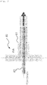
- FIG. 1 is a schematic view showing the configuration of a device for manufacture of polymeric micro-scaffolds according to an embodiment of the present invention
- FIG. 2 is a schematic view showing the configuration of a scaffold injector as a component of the device for manufacture of polymeric micro-scaffolds.
- a device (1) for manufacture of polymeric micro-scaffolds comprises a first 1 solution storage part (10), a second solution storage part (20), a gas storage part (30), a compression part (40), a pressure controller (50), a scaffold injector (60), and a scaffold production part (70).
- the first solution storage part (10), although not shown in detail, may have a dual vessel structure where a polymeric support structure solution is loaded to an inner vessel while deionized water contained in the outer vessel is heated to maintain a predetermined temperature of the inner vessel.
- the polymeric support structure solution may be formed by mixing a polymer solution and a biocompatible aqueous material solution useful for forming pores.
- the polymer solution may be made of a mixture of a polymer, dichloromethane (DCM), and a surfactant while the biocompatible aqueous material solution may be formed by mixing a biocompatible aqueous material and a PVA (polyvinyl alcohol) solution.
- DCM dichloromethane
- PVA polyvinyl alcohol
- the pore size distribution in the scaffold can be controlled depending on the composition of the polymer solution-biocompatible aqueous material solution mixture (particle size/concentration/ratio of the biocompatible aqueous material, concentration of the surfactant, and mixing rpm).
- any polymer may be used in the present invention.
- the polymer include PLGA (poly(lactic-co-glycolic acid)), PCL (polycaprolactone), PLA (poly-lactic acid), PGA (polyglutamic acid), PEG (poly-ethylene glycol), PLL (Poly-L-lysine), and copolymers thereof, but are not limited thereto.
- biocompatible aqueous material examples include, but are not limited to, gelatin, chitosan, hyaluronic acid, alginate, agarose, pectin, sodium carboxylate, chondroitin sulfate, and NaCl crystals.
- a PLGA solution may be formed by mixing dichloromethane (DCM), PLGA (75:25), and a surfactant.
- DCM dichloromethane
- PLGA PLGA
- a surfactant e.g., a surfactant for the biocompatible aqueous material
- PVA polyvinyl alcohol
- the first solution storage part (10) comprises a stirrer (11) which is used to prevent the layer separation of the polymer solution-biocompatible aqueous material solution mixture, for example, PLGA-gelatin mixture.
- the second solution storage part (20) may store an emulsifier solution.
- the emulsifier solution that may be stored in the second solution storage part (20) include PVA (poly vinyl alcohol), PVP (poly vinyl pyrrolidone), PEG (poly ethylene glycol), poloxamers, methylcellulose, Tween series, and/or mixture solutions thereof.
- a stirrer (21) for stirring the emulsifier solution.
- the gas storage part (30) communicates with both the first solution storage part (10) and the second solution storage part (20) via tubes or pipes and supplies to the first solution storage part 10 and the second solution storage part (20) a transporting gas for transporting the polymeric support structure solution and the emulsifier solution.
- the transporting gas may comprise any one of inactive gases, such as nitrogen (N 2 ), helium (He), neon (Ne), argon (Ar), krypton (Kr), xenon (Xe), radon (Rn), etc.
- inactive gases such as nitrogen (N 2 ), helium (He), neon (Ne), argon (Ar), krypton (Kr), xenon (Xe), radon (Rn), etc.
- the compression part (40) is to apply a pressure to the transporting gas provided for the first solution storage part (10) and the second solution storage part (20) and may comprise a micro pressure pump and may be arranged between the first solution storage part (10) and the gas storage part (30) and between the second solution storage part (20) and the gas storage part (30) .
- the compression part (40) may comprise a first compression module (41) and a second compression module (42) for applying a pressure to the transporting gas to supply the transporting gas to the first solution storage part (10) and the second solution storage part (20), respectively.
- the pressure controller (50) can control the first compression module (41) and the second compression module (42) of the compression part (40) independently so that different pressures are applied to the transporting gas influent to the first solution storage part (10) and the second storage part (20).
- the diameter distribution of the scaffolds can be controlled by a difference in pressure between the gases introduced into the containers.
- the ratio between the transporting gases supplied to the first solution storage part (10) and the second solution storage part (20) may range from 1:0.2 to 1:5.
- the pressure controller (50) may control the first compression module (41) so as to maintain the pressure of the transporting gas supplied to the first solution storage part (10) at 3 kPa to 50 kPa and particularly at 10 kPa.
- the pressure controller (50) may control the second compression module (41) so as to maintain the pressure of the transporting gas supplied to the second solution storage part (20) at 3 kPa to 30 kPa and particularly at 5 kPa.
- the device of the present invention may be configured to comprise multiple compression modules as needed.
- the scaffold injector (60) receives the polymeric support structure solution and the emulsifier solution respectively supplied from the first storage part (10) and the second solution storage part (20) by the transporting gas and can release a scaffold dispersion resulting from coupling between the polymeric support structure solution and the emulsifier solution.
- the scaffold injector (60) may comprise a first pipe (61) communicating with the second solution storage part (20) and passing the emulsifier solution therethrough and a second pipe (62) communicating with the first solution storage part (10) and passing the polymeric support structure solution therethrough.
- the scaffold injector (60) may have a dual pipe structure in which the second pipe (62) is arranged inside the first pipe (61) while the end of the second pipe (62) from which the polymeric support structure solution is released is located within the first pipe (61), whereby the scaffold dispersion can be released from the end of the first pipe (61).
- the second pipe should be smaller in diameter than the first pipe.
- the diameter distribution of the scaffold may be determined according to the diameters of the first pipe and/or the second pipe (62).
- the pipe diameter may range, for example, from 15 to 21 G (Gauge) (outer diameter: 0.82-1.83 mm, inner diameter: 0.51-1.37 mm) for the first pipe and, for example, from 19 to 34 G (Gauge) (inner diameter: 0.19-1.07 mm, outer diameter: 0.08-0.69 mm) for the second pipe.
- the first pipe (61) may be configured to supply the emulsifier solution to both sides of the second pipe (62) so that the emulsifier solution is homogeneously supplied.
- the second solution storage part (20) may be connected to the scaffold injector (60) via a 3-way valve (12).
- the first pipe (61) and the second pipe (62) may each be made of, for example, stainless steel, anticorrosive metal (titanium (Ti), cobalt (Co), chromium (Cr), nickel (Ni), silver (Ag), gold (Ag) and an alloy thereof) or an antichemical resin (PVC (poly-vinyl chloride), PU (poly-urethane), PP (polypropylene), PTFE (poly-tetrafluoroethylene), PFA (perfluoroalkoxy alkane) and/or ETFE (ethylene tetra fluoro ethylene) so that the pipes can be prevented from clogging with the coagulation of the polymer solution-biocompatible aqueous material solution mixture, for example, PLGA-gelatin mixture.
- anticorrosive metal titanium (Ti), cobalt (Co), chromium (Cr), nickel (Ni), silver (Ag), gold (Ag) and an alloy thereof
- PVC poly-vinyl chloride
- the scaffold production part (70) may have a dual vessel structure where the scaffold dispersion is loaded to an inner vessel while cooling water, for example, deionized water of 10°C is contained in the outer vessel to maintain a predetermined temperature of the inner vessel.
- cooling water for example, deionized water of 10°C
- the pore size distribution in the scaffold can be controlled depending on the temperature of the inner vessel.
- the pore size can be controlled within 40 to 90 pm.
- the scaffold production part (70) receives the scaffold dispersion released from the scaffold injector (60), removes the organic solvent and dispersion medium from the scaffold dispersion, and melts the internal gelatin particles to afford polymeric micro-scaffolds.
- a stirrer (71) may be installed inside the scaffold production part (70) to prevent the scaffolds from aggregation, which may happen during the evaporation of the residual organic solvent and the washing process.
- the polymeric micro-scaffolds produced in the scaffold production part (70) can be collected by the scaffold collector (80).
- the present invention provides a method for manufacturing a large amount of polymeric micro-scaffolds.
- the device (1) for manufacture of polymeric micro-scaffolds can stably manufacture polymeric micro-scaffolds uniform in size on mass scale and particularly, can drive in a continuous mode to allow the manufacture of polymeric micro-scaffolds on a large scale for a long period of time.
- 850 ⁇ L of the gelatin solution was added to the PLGA solution and mixed by vortexing at 3200 rpm for 2.5 minutes to form a PLGA-gelatin mixture.
- the present invention relates to a device for manufacturing a large amount of polymeric micro-scaffolds and, more particularly, to a device for manufacturing micro-scaffolds uniform in size on a mass scale.
Landscapes
- Health & Medical Sciences (AREA)
- Chemical & Material Sciences (AREA)
- Medicinal Chemistry (AREA)
- Engineering & Computer Science (AREA)
- Dermatology (AREA)
- Veterinary Medicine (AREA)
- Life Sciences & Earth Sciences (AREA)
- Public Health (AREA)
- General Health & Medical Sciences (AREA)
- Animal Behavior & Ethology (AREA)
- Oral & Maxillofacial Surgery (AREA)
- Transplantation (AREA)
- Epidemiology (AREA)
- Mechanical Engineering (AREA)
- Chemical Kinetics & Catalysis (AREA)
- Organic Chemistry (AREA)
- Robotics (AREA)
- Dispersion Chemistry (AREA)
- Polymers & Plastics (AREA)
- Materials Engineering (AREA)
- Manufacturing & Machinery (AREA)
- Microelectronics & Electronic Packaging (AREA)
- Medicinal Preparation (AREA)
- Colloid Chemistry (AREA)
- Processes Of Treating Macromolecular Substances (AREA)
Abstract
Description
- The present invention relates to a device for manufacturing a large amount of micro-scaffolds and, more specifically, to a device for manufacturing micro-scaffolds uniform in size on a mass scale.
- The present invention was made with the support of the Ministry of Science, ICT, and Future Planning of the Republic of Korea, under Project No. 2016M3A9E9941514, which was conducted under the research subject named "Development and Commercialization of Microstructure Targeting Technique for Cartilage Regeneration Substituent" within the program titled ""Project for Development of Original Technology in conjugation with Campus Medical Startup" by "Chonnam National University Hwasun Hospital" under management of the National Research Foundation of Korea, from 01 November 2016 to 31 July 2021.
- This application claims priority to Korean Patent Application No.
10-2018-0035464, filed on March 27, 2018 - Tissue engineering is the use of a combination of technologies, based on basic concepts and techniques of bioscience, medical science, and engineering, to maintain, improve, or restore body functions by making substituents for biological tissues and transplanting the substituents into a living body.
- In the practice of tissue engineering, cells are separated from a necessary tissue taken from a patient's body, amplified to a degree of necessity through cultivation, seeded into a porous biodegradable polymer matrix, and cultured in vitro for a predetermined period of time to manufacture scaffolds which are then transplanted back into the body.
- As such, the scaffold refers to a combination of a physical support and an adhesive substrate, which is designed to allow tissue cells to be cultured in vitro and transplanted in vivo. The scaffold may be fabricated into various shapes as needed.
- Particularly, the suitable field to the scaffold is applied is determined depending on the thicknesses of strands formed by spraying biocompatible materials and cells and the sizes of pores formed due to gaps between adjacent strands. Scaffolds can be manufactured to have desired sizes of pores by controlling the condition and environment in which molten biocompatible materials are sprayed.
- Methods for preparing porous nano- or microparticles having as large surface areas as possible are of important significance in various fields.
- For example, such porous nano- or microparticles can be used to fabricate batteries having a longer lifespan in the electrochemical field and to increase solar power efficiency in the alternative energy field. In the drug delivery field, when porous nano- or microparticles are provided as drug carriers to the surface of which drugs are applied or loaded, their increased surface areas per unit volume allow greater doses per unit, thereby giving maximal therapeutic efficiency at the same volume.
- Various products of polymer scaffolds having the advantageous surface area have already been marketed and developed into various shapes according to treatment sites and therapeutic purposes. However, the products are, in the most part, patch type products with a size of ones of centimeters, but do not function as a drug delivery system to be inserted into the body.
- Techniques for manufacture of micro-sized polymer scaffolds that can be inserted in vivo have been suggested in various ways. As for polymeric micro-scaffolds, however, their manufacture environments have a great influence on the sizes of the manufactured scaffolds. Even a slight change in the manufacturing condition results in a great difference in the products, which makes it difficult to commercialize such techniques.
- Of such manufacturing methods for polymeric micro-scaffolds, the use of a microfluidic channel and a double emulsion in combination has the advantage of allowing the user to control particle and pore sizes as desired and to manufacture polymeric micro-scaffolds suitable for desired purposes, but is disadvantageous in that the products with uniform sizes cannot be manufactured steadily to such an extent as to enable practical production, either.
- The present invention has been made to solve these problems and a purpose of the present invention is to provide a device for manufacture of polymeric micro-scaffolds, by which polymeric micro-scaffolds with uniform sizes can be manufactured stably in spite of changes of external conditions. In addition, another purpose of the present invention is to provide a method for manufacturing polymeric micro-scaffolds on a mass scale.
- In order to achieve the above purposes, an aspect of the present invention provides a device for manufacture of polymeric micro-scaffolds, the device comprising: a first solution storage part for storing a polymeric support structure solution; a second solution storage part for storing an emulsifier solution; a gas storage part, connected to both the first solution storage part and the second solution storage part, for providing a transporting gas for transporting the polymeric support structure solution and the emulsifier solution; a compression part for applying a pressure to the transporting gas supplied to the first solution storage part and the second solution storage part; a pressure controller for controlling the compression part so as to apply pressures to the transporting gas flowing into the first solution storage part and the second solution storage part, respectively; a scaffold injector for receiving the polymeric support structure solution and the emulsifier solution respectively supplied by the transporting gas and releasing a scaffold dispersion resulting from coupling between the polymeric support structure solution and the emulsifier solution; and a scaffold production part for receiving the scaffold dispersion released from the scaffold injector, removing an organic solvent and a dispersion medium from the scaffold dispersion, and producing polymeric micro-scaffolds.
- In the device for manufacture of polymeric micro-scaffolds according to the present invention, the polymeric support structure solution is formed by mixing a PLGA (poly(lactic-co-glycolic acid)) solution and a gelatin solution.
- In the device for manufacture of polymeric micro-scaffolds according to the present invention, the PLGA solution is formed by mixing dichloromethane (DCM), PLGA (75:25), and a surfactant, and the gelatin solution is formed by mixing a PVA (poly vinyl alcohol) solution and gelatin.
- In the device for manufacture of polymeric micro-scaffolds according to the present invention, the emulsifier solution is a 0.1-5 % PVA solution.
- In the device for manufacture of polymeric micro-scaffolds according to the present invention, the transporting gas supplied from the gas storage part is any one of nitrogen gas (N2) and inactive gas.
- In the device for manufacture of polymeric micro-scaffolds according to the present invention, the pressure controller controls the compression part so as to maintain a pressure of the transporting gas supplied to the first solution storage part at 3 kPa to 50 kPa.
- In the device for manufacture of polymeric micro-scaffolds according to the present invention, the pressure controller controls the compression part so as to maintain a pressure of the transporting gas supplied to the second solution storage part at 3 kPa to 30 kPa.
- In the device for manufacture of polymeric micro-scaffolds according to the present invention, the scaffold injector comprises a first pipe for supplying the emulsifier solution therethrough and a second pipe, arranged within the first pipe, for supplying the polymeric support structure solution therethrough, the second pipe having an end from which the polymeric support structure solution is released and which is located within the first pipe, whereby the scaffold dispersion is released from an end of the first pipe.
- In the device for manufacture of polymeric micro-scaffolds according to the present invention, the first pipe is configured to supply the emulsifier solution to both sides of the second pipe, and the first pipe and the second pipe are each made of a stainless steel material.
- In the device for manufacture of polymeric micro-scaffolds according to the present invention, the first solution storage part, the second solution storage part, and the scaffold production part are each adapted to have a stirrer installed therein.
- The device for manufacture of polymeric micro-scaffolds according to the present invention is advantageous in that the device can stably manufacture polymeric micro-scaffolds uniform in size in spite of changes of external conditions.
- In addition, the device can manufacture polymeric micro-scaffolds on a mass scale for a long period of time and particularly, can control sizes of the scaffolds manufactured thereby as well as sizes of pores formed in the scaffolds.
-
-
FIG. 1 is a schematic view showing the configuration of a device for manufacture of polymeric micro-scaffolds according to an embodiment of the present invention. -
FIG. 2 is a schematic view showing the configuration of a scaffold injector as a component of the device for manufacture of polymeric micro-scaffolds. -
FIG. 3 shows microscopic images of polymeric micro-scaffolds different in size that were manufactured by the device for manufacture of polymeric micro-scaffolds according to an embodiment of the present invention. -
FIG. 4 shows microscopic images of polymeric micro-scaffolds different in pore size that were manufactured by the device for manufacture of polymeric micro-scaffolds according to an embodiment of the present invention. - Hereinafter, preferred embodiments of the present invention will be described in detail with reference to the accompanying drawings. However, in the following description, a detailed explanation of known related technologies may be omitted to avoid unnecessarily obscuring the subject matter of the present invention.
- Since various variations may be performed on the exemplary embodiments according to the concept of the present invention and the embodiments of the present invention can be realized in a wide range of varied forms, specific exemplary embodiments of the present invention will be described herein in detail with reference to the appended drawings of the exemplary embodiments of the present invention. However, the present invention will not be limited only to the specific exemplary embodiments of the present invention which are disclosed herein. Therefore, it should be understood that the scope and spirit of the present invention can be extended to all variations, equivalents, and replacements in addition to the appended drawings of the present invention.
- According to an aspect thereof, the present invention provides a device for manufacture of polymer micro-scaffolds.
-
FIG. 1 is a schematic view showing the configuration of a device for manufacture of polymeric micro-scaffolds according to an embodiment of the present invention andFIG. 2 is a schematic view showing the configuration of a scaffold injector as a component of the device for manufacture of polymeric micro-scaffolds. - With reference to the figures a device (1) for manufacture of polymeric micro-scaffolds according to an embodiment of the present invention comprises a first 1 solution storage part (10), a second solution storage part (20), a gas storage part (30), a compression part (40), a pressure controller (50), a scaffold injector (60), and a scaffold production part (70).
- The first solution storage part (10), although not shown in detail, may have a dual vessel structure where a polymeric support structure solution is loaded to an inner vessel while deionized water contained in the outer vessel is heated to maintain a predetermined temperature of the inner vessel.
- In this regard, the polymeric support structure solution may be formed by mixing a polymer solution and a biocompatible aqueous material solution useful for forming pores. The polymer solution may be made of a mixture of a polymer, dichloromethane (DCM), and a surfactant while the biocompatible aqueous material solution may be formed by mixing a biocompatible aqueous material and a PVA (polyvinyl alcohol) solution.
- The pore size distribution in the scaffold can be controlled depending on the composition of the polymer solution-biocompatible aqueous material solution mixture (particle size/concentration/ratio of the biocompatible aqueous material, concentration of the surfactant, and mixing rpm).
- So long as it is hydrophobic and is dissolved in a volatile organic solvent, any polymer may be used in the present invention. Examples of the polymer include PLGA (poly(lactic-co-glycolic acid)), PCL (polycaprolactone), PLA (poly-lactic acid), PGA (polyglutamic acid), PEG (poly-ethylene glycol), PLL (Poly-L-lysine), and copolymers thereof, but are not limited thereto.
- Examples of the biocompatible aqueous material include, but are not limited to, gelatin, chitosan, hyaluronic acid, alginate, agarose, pectin, sodium carboxylate, chondroitin sulfate, and NaCl crystals.
- By way of example, when the polymer is PLGA, a PLGA solution may be formed by mixing dichloromethane (DCM), PLGA (75:25), and a surfactant. When the biocompatible aqueous material is gelatin, it may be mixed with a PVA (polyvinyl alcohol) solution to give a gelatin solution.
- Furthermore, the first solution storage part (10) comprises a stirrer (11) which is used to prevent the layer separation of the polymer solution-biocompatible aqueous material solution mixture, for example, PLGA-gelatin mixture.
- The second solution storage part (20) may store an emulsifier solution. Examples of the emulsifier solution that may be stored in the second solution storage part (20) include PVA (poly vinyl alcohol), PVP (poly vinyl pyrrolidone), PEG (poly ethylene glycol), poloxamers, methylcellulose, Tween series, and/or mixture solutions thereof. Inside the second solution storage part (20) is arranged a stirrer (21) for stirring the emulsifier solution.
- The gas storage part (30) communicates with both the first solution storage part (10) and the second solution storage part (20) via tubes or pipes and supplies to the first
solution storage part 10 and the second solution storage part (20) a transporting gas for transporting the polymeric support structure solution and the emulsifier solution. - The transporting gas may comprise any one of inactive gases, such as nitrogen (N2), helium (He), neon (Ne), argon (Ar), krypton (Kr), xenon (Xe), radon (Rn), etc.
- The compression part (40) is to apply a pressure to the transporting gas provided for the first solution storage part (10) and the second solution storage part (20) and may comprise a micro pressure pump and may be arranged between the first solution storage part (10) and the gas storage part (30) and between the second solution storage part (20) and the gas storage part (30) .
- As shown in the figure, the compression part (40) may comprise a first compression module (41) and a second compression module (42) for applying a pressure to the transporting gas to supply the transporting gas to the first solution storage part (10) and the second solution storage part (20), respectively.
- The pressure controller (50) can control the first compression module (41) and the second compression module (42) of the compression part (40) independently so that different pressures are applied to the transporting gas influent to the first solution storage part (10) and the second storage part (20). In this regard, the diameter distribution of the scaffolds can be controlled by a difference in pressure between the gases introduced into the containers.
- That is, the higher is the pressure of the transporting gas supplied to the first solution storage part (10), the greater the diameter of the scaffolds is. On the other hand, a higher pressure of the transporting gas supplied to the second solution storage part (20) makes the diameter of the scaffold smaller. The ratio between the transporting gases supplied to the first solution storage part (10) and the second solution storage part (20) may range from 1:0.2 to 1:5.
- The pressure controller (50) may control the first compression module (41) so as to maintain the pressure of the transporting gas supplied to the first solution storage part (10) at 3 kPa to 50 kPa and particularly at 10 kPa. In addition, the pressure controller (50) may control the second compression module (41) so as to maintain the pressure of the transporting gas supplied to the second solution storage part (20) at 3 kPa to 30 kPa and particularly at 5 kPa.
- Although shown to comprise the first compression module (41) and the second compression module (42) in the figure, the device of the present invention may be configured to comprise multiple compression modules as needed.
- The scaffold injector (60) receives the polymeric support structure solution and the emulsifier solution respectively supplied from the first storage part (10) and the second solution storage part (20) by the transporting gas and can release a scaffold dispersion resulting from coupling between the polymeric support structure solution and the emulsifier solution.
- As shown in
FIG. 2 , the scaffold injector (60) may comprise a first pipe (61) communicating with the second solution storage part (20) and passing the emulsifier solution therethrough and a second pipe (62) communicating with the first solution storage part (10) and passing the polymeric support structure solution therethrough. - Particularly, the scaffold injector (60) may have a dual pipe structure in which the second pipe (62) is arranged inside the first pipe (61) while the end of the second pipe (62) from which the polymeric support structure solution is released is located within the first pipe (61), whereby the scaffold dispersion can be released from the end of the first pipe (61). The second pipe should be smaller in diameter than the first pipe.
- In such a structure, the diameter distribution of the scaffold may be determined according to the diameters of the first pipe and/or the second pipe (62). The pipe diameter may range, for example, from 15 to 21 G (Gauge) (outer diameter: 0.82-1.83 mm, inner diameter: 0.51-1.37 mm) for the first pipe and, for example, from 19 to 34 G (Gauge) (inner diameter: 0.19-1.07 mm, outer diameter: 0.08-0.69 mm) for the second pipe.
- In addition, the first pipe (61) may be configured to supply the emulsifier solution to both sides of the second pipe (62) so that the emulsifier solution is homogeneously supplied. Thus, the second solution storage part (20) may be connected to the scaffold injector (60) via a 3-way valve (12).
- The first pipe (61) and the second pipe (62) may each be made of, for example, stainless steel, anticorrosive metal (titanium (Ti), cobalt (Co), chromium (Cr), nickel (Ni), silver (Ag), gold (Ag) and an alloy thereof) or an antichemical resin (PVC (poly-vinyl chloride), PU (poly-urethane), PP (polypropylene), PTFE (poly-tetrafluoroethylene), PFA (perfluoroalkoxy alkane) and/or ETFE (ethylene tetra fluoro ethylene) so that the pipes can be prevented from clogging with the coagulation of the polymer solution-biocompatible aqueous material solution mixture, for example, PLGA-gelatin mixture.
- Although not shown in detail, the scaffold production part (70) may have a dual vessel structure where the scaffold dispersion is loaded to an inner vessel while cooling water, for example, deionized water of 10°C is contained in the outer vessel to maintain a predetermined temperature of the inner vessel. In this context, the pore size distribution in the scaffold can be controlled depending on the temperature of the inner vessel.
- That is, the lower is the temperature of the inner vessel, the smaller the pore size is. At 0 to 25°C, the pore size can be controlled within 40 to 90 pm.
- The scaffold production part (70) receives the scaffold dispersion released from the scaffold injector (60), removes the organic solvent and dispersion medium from the scaffold dispersion, and melts the internal gelatin particles to afford polymeric micro-scaffolds.
- Furthermore, a stirrer (71) may be installed inside the scaffold production part (70) to prevent the scaffolds from aggregation, which may happen during the evaporation of the residual organic solvent and the washing process.
- The polymeric micro-scaffolds produced in the scaffold production part (70) can be collected by the scaffold collector (80).
- According to another aspect thereof, the present invention provides a method for manufacturing a large amount of polymeric micro-scaffolds.
- The device (1) for manufacture of polymeric micro-scaffolds can stably manufacture polymeric micro-scaffolds uniform in size on mass scale and particularly, can drive in a continuous mode to allow the manufacture of polymeric micro-scaffolds on a large scale for a long period of time.
- Thus, a description of overlapping contents in the manufacture of the polymeric micro-scaffolds is omitted to avoid excessive complexity of the present specification.
- In a 2-mL tube, 931 mL of dichloromethane (DCM), 70 mg of PLGA (75:25), and 15 µL of Span80 were mixed by vortexing for 7 minutes at 3200 rpm to prepare a PLGA solution.
- In 100-mL media bottle, 50 m1 of a 1 % PVA solution was put, followed by 3 g of gelatin. Subsequently, the media bottle was heated to 40°C while dispersing the gelatin by stirring to prepare a gelatin solution.
- In a 2-mL tube, 850 µL of the gelatin solution was added to the PLGA solution and mixed by vortexing at 3200 rpm for 2.5 minutes to form a PLGA-gelatin mixture.
- In a media bottle, 400 mL of DI-water and 4 g of PVA were heated together at 200°C while stirring at 500 rpm for 1 hour to dissolve PVA to prepare a 1 % PVA solution.
-
- ① 1.9 mL of the PLGA-gelatin mixture and 400 mL of the 1 % PVA solution were loaded to respective vessels.
- ② 500 mL of DI-water was introduced into the production vessel as the scaffold production part.
- ③ The PLGA-gelatin mixture was stirred at 1500 rpm and maintained at 35°C.
- ④ In the production vessel, the DI-water was stirred at 250 rpm and maintained at 10°C.
-
- ① Using a micro pressure pump, the injection pressure of nitrogen (N2) gas was adjusted and set to be 10 kPa for the PLGA-gelatin mixture and 5 kPa for the 1 % PVA solution. With the aid of the injected nitrogen gas, the PLGA-gelatin mixture and the 1 % PVA solution were transported to the scaffold injector.
- ② A scaffold dispersion was generated in the scaffold injector and sprayed through the scaffold injector into a production vessel to manufacture scaffolds.
- ③ The scaffolds thus obtained were left for 4 hours in the production vessel (while stirring at a constant temperature) to evaporate residual organic solvents.
- ④ In the production vessel, the stirring was stopped to settle down the scaffolds and the dispersion medium was removed, followed by adding 35°C DI-water to dissolve the gelatin particles present inside the scaffolds (stirring for about 5 minutes).
- ⑤ Step ③ was repeated 3-5 times to wash the polymeric micro-scaffolds until the dispersion medium became completely clear.
- ⑥ The washed polymeric micro-scaffolds were settled down and transferred to a 30-ml collection vessel filled with DI-water.
- Through the manufacturing procedure described above, polymeric micro-scaffolds were manufactured as shown in
FIGS. 3 and4 . - While this invention has been described in connection with what is presently considered to be practical exemplary embodiments, it is to be understood that the invention is not limited to the disclosed embodiments, but, on the contrary, is intended to cover various modifications and equivalent arrangements included within the spirit and scope of the appended claims.
-
- 1: Device for manufacture of polymeric micro-scaffold
- 10: First solution storage part
- 20: Second solution storage part
- 30: Gas storage part
- 40: Compression part
- 50: Pressure controller
- 60: scaffold injector
- 70: scaffold production part
- The present invention relates to a device for manufacturing a large amount of polymeric micro-scaffolds and, more particularly, to a device for manufacturing micro-scaffolds uniform in size on a mass scale.
Claims (12)
- A device for manufacture of polymeric micro-scaffolds, the device comprising:a first solution storage part for storing a polymeric support structure solution;a second solution storage part for storing an emulsifier solution;a gas storage part, connected to both the first solution storage part and the second solution storage part, for providing a transporting gas for transporting the polymeric support structure solution and the emulsifier solution;a compression part for applying a pressure to the transporting gas supplied to the first solution storage part and the second solution storage part;a pressure controller for controlling the compression part so as to apply pressures to the transporting gas flowing into the first solution storage part and the second solution storage part, respectively;a scaffold injector for receiving the polymeric support structure solution and the emulsifier solution respectively supplied by the transporting gas and releasing a scaffold dispersion resulting from coupling between the polymeric support structure solution and the emulsifier solution; anda scaffold production part for receiving the scaffold dispersion released from the scaffold injector, removing an organic solvent and a dispersion medium from the scaffold dispersion, and producing polymeric micro-scaffolds.
- The device of claim 1, wherein the polymeric support structure solution is formed by mixing a PLGA (poly(lactic-co-glycolic acid)) solution and a gelatin solution.
- The device of claim 2, wherein the PLGA solution is formed by mixing dichloromethane (DCM), PLGA (75:25), and a surfactant.
- The device of claim 2, wherein the gelatin solution is formed by mixing a PVA (poly vinyl alcohol) solution and gelatin.
- The device of claim 1, wherein the emulsifier solution is a 0.1-5 % PVA solution.
- The device of claim 1, wherein the transporting gas supplied from the gas storage part is any one of nitrogen gas (N2) and inactive gas.
- The device of claim 1, wherein the pressure controller controls the compression part so as to maintain a pressure of the transporting gas supplied to the first solution storage part at 3 kPa to 50 kPa.
- The device of claim 1, wherein the pressure controller controls the compression part so as to maintain a pressure of the transporting gas supplied to the second solution storage part at 3 kPa to 30 kPa.
- The device of claim 1, wherein the scaffold injector comprises a first pipe for supplying the emulsifier solution therethrough and a second pipe, arranged within the first pipe, for supplying the polymeric support structure solution therethrough, the second pipe having an end from which the polymeric support structure solution is released and which is located within the first pipe, whereby the scaffold dispersion is released from an end of the first pipe.
- The device of claim 9, wherein the first pipe is configured to supply the emulsifier solution to both sides of the second pipe.
- The device of claim 9, wherein the first pipe and the second pipe are each made of a stainless steel material.
- The device of claim 1, wherein the first solution storage part, the second solution storage part, and the scaffold production part are each adapted to have a stirrer installed therein.
Applications Claiming Priority (2)
| Application Number | Priority Date | Filing Date | Title |
|---|---|---|---|
| KR1020180035464A KR20190113160A (en) | 2018-03-27 | 2018-03-27 | Apparatus for mass-preparing polymer micro-scaffold |
| PCT/KR2019/003482 WO2019190155A1 (en) | 2018-03-27 | 2019-03-26 | Device for manufacturing large amount of polymer micro-scaffolds |
Publications (3)
| Publication Number | Publication Date |
|---|---|
| EP3777908A1 true EP3777908A1 (en) | 2021-02-17 |
| EP3777908A4 EP3777908A4 (en) | 2021-05-05 |
| EP3777908B1 EP3777908B1 (en) | 2022-06-08 |
Family
ID=68059297
Family Applications (1)
| Application Number | Title | Priority Date | Filing Date |
|---|---|---|---|
| EP19774284.4A Active EP3777908B1 (en) | 2018-03-27 | 2019-03-26 | Device for manufacturing large amount of polymer micro-scaffolds |
Country Status (4)
| Country | Link |
|---|---|
| US (1) | US12128585B2 (en) |
| EP (1) | EP3777908B1 (en) |
| KR (1) | KR20190113160A (en) |
| WO (1) | WO2019190155A1 (en) |
Family Cites Families (6)
| Publication number | Priority date | Publication date | Assignee | Title |
|---|---|---|---|---|
| KR101140360B1 (en) * | 2005-12-20 | 2012-05-23 | 주식회사 삼양바이오팜 | Method for preparing microspheres of polymer and manufacturing apparatus therof |
| KR100924236B1 (en) | 2009-06-23 | 2009-10-29 | 충남대학교산학협력단 | Novel manufacturing method and device for ultrafine particles having uniform particle size distribution |
| KR101663150B1 (en) * | 2014-03-18 | 2016-10-07 | 단국대학교 천안캠퍼스 산학협력단 | Porous polymer sphere, method for preparing thereof, and biodegradable materials for tissue engineering using the same |
| KR101521552B1 (en) * | 2014-06-30 | 2015-05-19 | 경북대학교 산학협력단 | Bio-device using polymer film with polymer particle, and preparation method thereof |
| KR101649798B1 (en) | 2014-09-30 | 2016-08-22 | 단국대학교 천안캠퍼스 산학협력단 | Method for preparation of biodegradable polymer scaffold with microporous structure |
| KR101858074B1 (en) | 2016-09-29 | 2018-05-15 | 한국항공우주연구원 | Lifting apparatus and lifting method of using the same |
-
2018
- 2018-03-27 KR KR1020180035464A patent/KR20190113160A/en not_active Ceased
-
2019
- 2019-03-26 EP EP19774284.4A patent/EP3777908B1/en active Active
- 2019-03-26 WO PCT/KR2019/003482 patent/WO2019190155A1/en not_active Ceased
- 2019-03-26 US US16/976,413 patent/US12128585B2/en active Active
Also Published As
| Publication number | Publication date |
|---|---|
| EP3777908B1 (en) | 2022-06-08 |
| WO2019190155A1 (en) | 2019-10-03 |
| EP3777908A4 (en) | 2021-05-05 |
| US20210379799A1 (en) | 2021-12-09 |
| KR20190113160A (en) | 2019-10-08 |
| US12128585B2 (en) | 2024-10-29 |
Similar Documents
| Publication | Publication Date | Title |
|---|---|---|
| Huang et al. | Rapid fabrication of bio‐inspired 3D microfluidic vascular networks | |
| EP1245670A2 (en) | Method and apparatus for culturing cells | |
| JP4187167B2 (en) | Modified cross-section hollow fiber membrane cell-containing device | |
| Li et al. | Biocatalytic living materials built by compartmentalized microorganisms in annealable granular hydrogels | |
| CN103435836B (en) | Preparation method of polymer foam material in open pore structure | |
| JP2008255298A (en) | Fibroin sponge body and method for producing the same | |
| CN103767804A (en) | Vascularizing tissue structure with microfluid passage and preparation method thereof | |
| CN108424533B (en) | A kind of 3D printing biomedical hydrogel and preparation method thereof | |
| CN102309782B (en) | Preparation method of living cell based complex three-dimensional microchannel porous support | |
| He et al. | Layer-by-layer micromolding of natural biopolymer scaffolds with intrinsic microfluidic networks | |
| CN104740688B (en) | Preparation method of microsphere close-packed shape memory porous scaffold | |
| Warburton et al. | A modular three-dimensional bioprinter for printing porous scaffolds for tissue engineering | |
| Jiang et al. | Janus hydrogels: merging boundaries in tissue engineering for enhanced biomaterials and regenerative therapies | |
| US9957481B2 (en) | Scaffolds and other cell-growth structures using microfluidics to culture biological samples | |
| CN103623497B (en) | A kind of drug delivery sacculus dilating catheter | |
| McCarthy et al. | Large‐scale synthesis of compressible and re‐expandable three‐dimensional nanofiber matrices | |
| CN105833343B (en) | A kind of preparation method of the netted alginate porous material of honeycomb as artificial skin | |
| US12128585B2 (en) | Device for manufacturing large amount of polymeric micro-scaffolds | |
| CN112917899A (en) | Biological 3D printing method based on porous structure | |
| JP6594066B2 (en) | Cell culture container, cell culture apparatus and cell culture method | |
| Sun et al. | An off-the-shelf microfluidic device for the controllable fabrication of multiple-holed hollow particles and their cell culture applications | |
| KR20210037404A (en) | Apparatus for mass-preparing polymer micro-scaffold and mass-preparation process using the same | |
| CN105770990B (en) | A kind of preparation method of artificial skin timbering material | |
| CN104371140A (en) | A Novel Polyurethane Foam with Oriented Structure | |
| CN1994243A (en) | Dual-scale micro-structure artificial bone scaffold and preparation method thereof |
Legal Events
| Date | Code | Title | Description |
|---|---|---|---|
| STAA | Information on the status of an ep patent application or granted ep patent |
Free format text: STATUS: THE INTERNATIONAL PUBLICATION HAS BEEN MADE |
|
| PUAI | Public reference made under article 153(3) epc to a published international application that has entered the european phase |
Free format text: ORIGINAL CODE: 0009012 |
|
| STAA | Information on the status of an ep patent application or granted ep patent |
Free format text: STATUS: REQUEST FOR EXAMINATION WAS MADE |
|
| 17P | Request for examination filed |
Effective date: 20200824 |
|
| AK | Designated contracting states |
Kind code of ref document: A1 Designated state(s): AL AT BE BG CH CY CZ DE DK EE ES FI FR GB GR HR HU IE IS IT LI LT LU LV MC MK MT NL NO PL PT RO RS SE SI SK SM TR |
|
| AX | Request for extension of the european patent |
Extension state: BA ME |
|
| RIN1 | Information on inventor provided before grant (corrected) |
Inventor name: CHOI, EUN PYO Inventor name: PARK, JONG OH Inventor name: KIM, CHANG SEI Inventor name: KANG, BYUNG JEON Inventor name: KIM, SEOK JAE Inventor name: GO, GWANG JUN Inventor name: CHANG, YEONG JUN |
|
| A4 | Supplementary search report drawn up and despatched |
Effective date: 20210408 |
|
| RIC1 | Information provided on ipc code assigned before grant |
Ipc: A61L 27/56 20060101AFI20210331BHEP Ipc: A61L 27/26 20060101ALI20210331BHEP Ipc: A61L 27/20 20060101ALI20210331BHEP Ipc: A61L 27/22 20060101ALI20210331BHEP Ipc: B81C 99/00 20100101ALI20210331BHEP Ipc: C08J 9/00 20060101ALI20210331BHEP Ipc: B29C 44/00 20060101ALI20210331BHEP Ipc: C08J 9/28 20060101ALI20210331BHEP Ipc: C08J 9/26 20060101ALI20210331BHEP |
|
| DAV | Request for validation of the european patent (deleted) | ||
| DAX | Request for extension of the european patent (deleted) | ||
| GRAP | Despatch of communication of intention to grant a patent |
Free format text: ORIGINAL CODE: EPIDOSNIGR1 |
|
| STAA | Information on the status of an ep patent application or granted ep patent |
Free format text: STATUS: GRANT OF PATENT IS INTENDED |
|
| INTG | Intention to grant announced |
Effective date: 20211220 |
|
| GRAS | Grant fee paid |
Free format text: ORIGINAL CODE: EPIDOSNIGR3 |
|
| GRAA | (expected) grant |
Free format text: ORIGINAL CODE: 0009210 |
|
| STAA | Information on the status of an ep patent application or granted ep patent |
Free format text: STATUS: THE PATENT HAS BEEN GRANTED |
|
| AK | Designated contracting states |
Kind code of ref document: B1 Designated state(s): AL AT BE BG CH CY CZ DE DK EE ES FI FR GB GR HR HU IE IS IT LI LT LU LV MC MK MT NL NO PL PT RO RS SE SI SK SM TR |
|
| REG | Reference to a national code |
Ref country code: AT Ref legal event code: REF Ref document number: 1496471 Country of ref document: AT Kind code of ref document: T Effective date: 20220615 Ref country code: CH Ref legal event code: EP |
|
| REG | Reference to a national code |
Ref country code: DE Ref legal event code: R096 Ref document number: 602019015748 Country of ref document: DE |
|
| REG | Reference to a national code |
Ref country code: IE Ref legal event code: FG4D |
|
| REG | Reference to a national code |
Ref country code: LT Ref legal event code: MG9D |
|
| REG | Reference to a national code |
Ref country code: NL Ref legal event code: MP Effective date: 20220608 |
|
| PG25 | Lapsed in a contracting state [announced via postgrant information from national office to epo] |
Ref country code: SE Free format text: LAPSE BECAUSE OF FAILURE TO SUBMIT A TRANSLATION OF THE DESCRIPTION OR TO PAY THE FEE WITHIN THE PRESCRIBED TIME-LIMIT Effective date: 20220608 Ref country code: NO Free format text: LAPSE BECAUSE OF FAILURE TO SUBMIT A TRANSLATION OF THE DESCRIPTION OR TO PAY THE FEE WITHIN THE PRESCRIBED TIME-LIMIT Effective date: 20220908 Ref country code: LT Free format text: LAPSE BECAUSE OF FAILURE TO SUBMIT A TRANSLATION OF THE DESCRIPTION OR TO PAY THE FEE WITHIN THE PRESCRIBED TIME-LIMIT Effective date: 20220608 Ref country code: HR Free format text: LAPSE BECAUSE OF FAILURE TO SUBMIT A TRANSLATION OF THE DESCRIPTION OR TO PAY THE FEE WITHIN THE PRESCRIBED TIME-LIMIT Effective date: 20220608 Ref country code: GR Free format text: LAPSE BECAUSE OF FAILURE TO SUBMIT A TRANSLATION OF THE DESCRIPTION OR TO PAY THE FEE WITHIN THE PRESCRIBED TIME-LIMIT Effective date: 20220909 Ref country code: FI Free format text: LAPSE BECAUSE OF FAILURE TO SUBMIT A TRANSLATION OF THE DESCRIPTION OR TO PAY THE FEE WITHIN THE PRESCRIBED TIME-LIMIT Effective date: 20220608 Ref country code: BG Free format text: LAPSE BECAUSE OF FAILURE TO SUBMIT A TRANSLATION OF THE DESCRIPTION OR TO PAY THE FEE WITHIN THE PRESCRIBED TIME-LIMIT Effective date: 20220908 |
|
| REG | Reference to a national code |
Ref country code: AT Ref legal event code: MK05 Ref document number: 1496471 Country of ref document: AT Kind code of ref document: T Effective date: 20220608 |
|
| PG25 | Lapsed in a contracting state [announced via postgrant information from national office to epo] |
Ref country code: RS Free format text: LAPSE BECAUSE OF FAILURE TO SUBMIT A TRANSLATION OF THE DESCRIPTION OR TO PAY THE FEE WITHIN THE PRESCRIBED TIME-LIMIT Effective date: 20220608 Ref country code: LV Free format text: LAPSE BECAUSE OF FAILURE TO SUBMIT A TRANSLATION OF THE DESCRIPTION OR TO PAY THE FEE WITHIN THE PRESCRIBED TIME-LIMIT Effective date: 20220608 |
|
| PG25 | Lapsed in a contracting state [announced via postgrant information from national office to epo] |
Ref country code: NL Free format text: LAPSE BECAUSE OF FAILURE TO SUBMIT A TRANSLATION OF THE DESCRIPTION OR TO PAY THE FEE WITHIN THE PRESCRIBED TIME-LIMIT Effective date: 20220608 |
|
| PG25 | Lapsed in a contracting state [announced via postgrant information from national office to epo] |
Ref country code: SM Free format text: LAPSE BECAUSE OF FAILURE TO SUBMIT A TRANSLATION OF THE DESCRIPTION OR TO PAY THE FEE WITHIN THE PRESCRIBED TIME-LIMIT Effective date: 20220608 Ref country code: SK Free format text: LAPSE BECAUSE OF FAILURE TO SUBMIT A TRANSLATION OF THE DESCRIPTION OR TO PAY THE FEE WITHIN THE PRESCRIBED TIME-LIMIT Effective date: 20220608 Ref country code: RO Free format text: LAPSE BECAUSE OF FAILURE TO SUBMIT A TRANSLATION OF THE DESCRIPTION OR TO PAY THE FEE WITHIN THE PRESCRIBED TIME-LIMIT Effective date: 20220608 Ref country code: PT Free format text: LAPSE BECAUSE OF FAILURE TO SUBMIT A TRANSLATION OF THE DESCRIPTION OR TO PAY THE FEE WITHIN THE PRESCRIBED TIME-LIMIT Effective date: 20221010 Ref country code: ES Free format text: LAPSE BECAUSE OF FAILURE TO SUBMIT A TRANSLATION OF THE DESCRIPTION OR TO PAY THE FEE WITHIN THE PRESCRIBED TIME-LIMIT Effective date: 20220608 Ref country code: EE Free format text: LAPSE BECAUSE OF FAILURE TO SUBMIT A TRANSLATION OF THE DESCRIPTION OR TO PAY THE FEE WITHIN THE PRESCRIBED TIME-LIMIT Effective date: 20220608 Ref country code: CZ Free format text: LAPSE BECAUSE OF FAILURE TO SUBMIT A TRANSLATION OF THE DESCRIPTION OR TO PAY THE FEE WITHIN THE PRESCRIBED TIME-LIMIT Effective date: 20220608 Ref country code: AT Free format text: LAPSE BECAUSE OF FAILURE TO SUBMIT A TRANSLATION OF THE DESCRIPTION OR TO PAY THE FEE WITHIN THE PRESCRIBED TIME-LIMIT Effective date: 20220608 |
|
| PG25 | Lapsed in a contracting state [announced via postgrant information from national office to epo] |
Ref country code: PL Free format text: LAPSE BECAUSE OF FAILURE TO SUBMIT A TRANSLATION OF THE DESCRIPTION OR TO PAY THE FEE WITHIN THE PRESCRIBED TIME-LIMIT Effective date: 20220608 Ref country code: IS Free format text: LAPSE BECAUSE OF FAILURE TO SUBMIT A TRANSLATION OF THE DESCRIPTION OR TO PAY THE FEE WITHIN THE PRESCRIBED TIME-LIMIT Effective date: 20221008 |
|
| REG | Reference to a national code |
Ref country code: DE Ref legal event code: R097 Ref document number: 602019015748 Country of ref document: DE |
|
| PG25 | Lapsed in a contracting state [announced via postgrant information from national office to epo] |
Ref country code: AL Free format text: LAPSE BECAUSE OF FAILURE TO SUBMIT A TRANSLATION OF THE DESCRIPTION OR TO PAY THE FEE WITHIN THE PRESCRIBED TIME-LIMIT Effective date: 20220608 |
|
| PLBE | No opposition filed within time limit |
Free format text: ORIGINAL CODE: 0009261 |
|
| STAA | Information on the status of an ep patent application or granted ep patent |
Free format text: STATUS: NO OPPOSITION FILED WITHIN TIME LIMIT |
|
| PG25 | Lapsed in a contracting state [announced via postgrant information from national office to epo] |
Ref country code: DK Free format text: LAPSE BECAUSE OF FAILURE TO SUBMIT A TRANSLATION OF THE DESCRIPTION OR TO PAY THE FEE WITHIN THE PRESCRIBED TIME-LIMIT Effective date: 20220608 |
|
| 26N | No opposition filed |
Effective date: 20230310 |
|
| PG25 | Lapsed in a contracting state [announced via postgrant information from national office to epo] |
Ref country code: SI Free format text: LAPSE BECAUSE OF FAILURE TO SUBMIT A TRANSLATION OF THE DESCRIPTION OR TO PAY THE FEE WITHIN THE PRESCRIBED TIME-LIMIT Effective date: 20220608 |
|
| PG25 | Lapsed in a contracting state [announced via postgrant information from national office to epo] |
Ref country code: MC Free format text: LAPSE BECAUSE OF FAILURE TO SUBMIT A TRANSLATION OF THE DESCRIPTION OR TO PAY THE FEE WITHIN THE PRESCRIBED TIME-LIMIT Effective date: 20220608 |
|
| REG | Reference to a national code |
Ref country code: CH Ref legal event code: PL |
|
| REG | Reference to a national code |
Ref country code: BE Ref legal event code: MM Effective date: 20230331 |
|
| PG25 | Lapsed in a contracting state [announced via postgrant information from national office to epo] |
Ref country code: LU Free format text: LAPSE BECAUSE OF NON-PAYMENT OF DUE FEES Effective date: 20230326 |
|
| REG | Reference to a national code |
Ref country code: IE Ref legal event code: MM4A |
|
| PG25 | Lapsed in a contracting state [announced via postgrant information from national office to epo] |
Ref country code: LI Free format text: LAPSE BECAUSE OF NON-PAYMENT OF DUE FEES Effective date: 20230331 Ref country code: IT Free format text: LAPSE BECAUSE OF FAILURE TO SUBMIT A TRANSLATION OF THE DESCRIPTION OR TO PAY THE FEE WITHIN THE PRESCRIBED TIME-LIMIT Effective date: 20220608 Ref country code: IE Free format text: LAPSE BECAUSE OF NON-PAYMENT OF DUE FEES Effective date: 20230326 Ref country code: CH Free format text: LAPSE BECAUSE OF NON-PAYMENT OF DUE FEES Effective date: 20230331 Ref country code: FR Free format text: LAPSE BECAUSE OF NON-PAYMENT OF DUE FEES Effective date: 20230331 |
|
| PG25 | Lapsed in a contracting state [announced via postgrant information from national office to epo] |
Ref country code: BE Free format text: LAPSE BECAUSE OF NON-PAYMENT OF DUE FEES Effective date: 20230331 |
|
| PG25 | Lapsed in a contracting state [announced via postgrant information from national office to epo] |
Ref country code: BG Free format text: LAPSE BECAUSE OF FAILURE TO SUBMIT A TRANSLATION OF THE DESCRIPTION OR TO PAY THE FEE WITHIN THE PRESCRIBED TIME-LIMIT Effective date: 20220608 |
|
| PG25 | Lapsed in a contracting state [announced via postgrant information from national office to epo] |
Ref country code: BG Free format text: LAPSE BECAUSE OF FAILURE TO SUBMIT A TRANSLATION OF THE DESCRIPTION OR TO PAY THE FEE WITHIN THE PRESCRIBED TIME-LIMIT Effective date: 20220608 |
|
| PGFP | Annual fee paid to national office [announced via postgrant information from national office to epo] |
Ref country code: DE Payment date: 20250319 Year of fee payment: 7 |
|
| PGFP | Annual fee paid to national office [announced via postgrant information from national office to epo] |
Ref country code: GB Payment date: 20250324 Year of fee payment: 7 |
|
| PG25 | Lapsed in a contracting state [announced via postgrant information from national office to epo] |
Ref country code: CY Free format text: LAPSE BECAUSE OF FAILURE TO SUBMIT A TRANSLATION OF THE DESCRIPTION OR TO PAY THE FEE WITHIN THE PRESCRIBED TIME-LIMIT; INVALID AB INITIO Effective date: 20190326 |
|
| PG25 | Lapsed in a contracting state [announced via postgrant information from national office to epo] |
Ref country code: HU Free format text: LAPSE BECAUSE OF FAILURE TO SUBMIT A TRANSLATION OF THE DESCRIPTION OR TO PAY THE FEE WITHIN THE PRESCRIBED TIME-LIMIT; INVALID AB INITIO Effective date: 20190326 |
|
| PG25 | Lapsed in a contracting state [announced via postgrant information from national office to epo] |
Ref country code: TR Free format text: LAPSE BECAUSE OF FAILURE TO SUBMIT A TRANSLATION OF THE DESCRIPTION OR TO PAY THE FEE WITHIN THE PRESCRIBED TIME-LIMIT Effective date: 20220608 |