EP3777754B1 - Integrated dental implant abutments - Google Patents
Integrated dental implant abutments Download PDFInfo
- Publication number
- EP3777754B1 EP3777754B1 EP20188558.9A EP20188558A EP3777754B1 EP 3777754 B1 EP3777754 B1 EP 3777754B1 EP 20188558 A EP20188558 A EP 20188558A EP 3777754 B1 EP3777754 B1 EP 3777754B1
- Authority
- EP
- European Patent Office
- Prior art keywords
- dental
- dental abutment
- abutment
- shoulder
- retention element
- Prior art date
- Legal status (The legal status is an assumption and is not a legal conclusion. Google has not performed a legal analysis and makes no representation as to the accuracy of the status listed.)
- Active
Links
- 239000004053 dental implant Substances 0.000 title description 22
- 230000014759 maintenance of location Effects 0.000 claims description 16
- 239000007943 implant Substances 0.000 description 11
- 230000004048 modification Effects 0.000 description 9
- 238000012986 modification Methods 0.000 description 9
- 210000003739 neck Anatomy 0.000 description 8
- 238000000034 method Methods 0.000 description 5
- 210000000988 bone and bone Anatomy 0.000 description 3
- 238000005516 engineering process Methods 0.000 description 3
- 239000000463 material Substances 0.000 description 3
- 239000004696 Poly ether ether ketone Substances 0.000 description 2
- 238000005422 blasting Methods 0.000 description 2
- 239000002978 dental impression material Substances 0.000 description 2
- 229920002530 polyetherether ketone Polymers 0.000 description 2
- 208000006735 Periostitis Diseases 0.000 description 1
- 229910001069 Ti alloy Inorganic materials 0.000 description 1
- 230000001580 bacterial effect Effects 0.000 description 1
- 239000007767 bonding agent Substances 0.000 description 1
- 230000008468 bone growth Effects 0.000 description 1
- 239000003795 chemical substances by application Substances 0.000 description 1
- 239000002131 composite material Substances 0.000 description 1
- 239000000805 composite resin Substances 0.000 description 1
- 230000010485 coping Effects 0.000 description 1
- 239000005548 dental material Substances 0.000 description 1
- 239000004851 dental resin Substances 0.000 description 1
- 210000004513 dentition Anatomy 0.000 description 1
- 238000002513 implantation Methods 0.000 description 1
- 208000028867 ischemia Diseases 0.000 description 1
- 238000002955 isolation Methods 0.000 description 1
- 229910052751 metal Inorganic materials 0.000 description 1
- 239000002184 metal Substances 0.000 description 1
- -1 opaque (i.e. Substances 0.000 description 1
- 230000001582 osteoblastic effect Effects 0.000 description 1
- 210000003460 periosteum Anatomy 0.000 description 1
- 239000000126 substance Substances 0.000 description 1
- 210000001519 tissue Anatomy 0.000 description 1
- 230000036346 tooth eruption Effects 0.000 description 1
- 230000007704 transition Effects 0.000 description 1
- 238000003466 welding Methods 0.000 description 1
Images


Classifications
-
- A—HUMAN NECESSITIES
- A61—MEDICAL OR VETERINARY SCIENCE; HYGIENE
- A61C—DENTISTRY; APPARATUS OR METHODS FOR ORAL OR DENTAL HYGIENE
- A61C8/00—Means to be fixed to the jaw-bone for consolidating natural teeth or for fixing dental prostheses thereon; Dental implants; Implanting tools
- A61C8/0048—Connecting the upper structure to the implant, e.g. bridging bars
- A61C8/005—Connecting devices for joining an upper structure with an implant member, e.g. spacers
- A61C8/0069—Connecting devices for joining an upper structure with an implant member, e.g. spacers tapered or conical connection
- A61C8/0071—Connecting devices for joining an upper structure with an implant member, e.g. spacers tapered or conical connection with a self-locking taper, e.g. morse taper
-
- A—HUMAN NECESSITIES
- A61—MEDICAL OR VETERINARY SCIENCE; HYGIENE
- A61C—DENTISTRY; APPARATUS OR METHODS FOR ORAL OR DENTAL HYGIENE
- A61C8/00—Means to be fixed to the jaw-bone for consolidating natural teeth or for fixing dental prostheses thereon; Dental implants; Implanting tools
- A61C8/0048—Connecting the upper structure to the implant, e.g. bridging bars
-
- A—HUMAN NECESSITIES
- A61—MEDICAL OR VETERINARY SCIENCE; HYGIENE
- A61C—DENTISTRY; APPARATUS OR METHODS FOR ORAL OR DENTAL HYGIENE
- A61C8/00—Means to be fixed to the jaw-bone for consolidating natural teeth or for fixing dental prostheses thereon; Dental implants; Implanting tools
- A61C8/0018—Means to be fixed to the jaw-bone for consolidating natural teeth or for fixing dental prostheses thereon; Dental implants; Implanting tools characterised by the shape
- A61C8/0037—Details of the shape
- A61C2008/0046—Textured surface, e.g. roughness, microstructure
-
- A—HUMAN NECESSITIES
- A61—MEDICAL OR VETERINARY SCIENCE; HYGIENE
- A61C—DENTISTRY; APPARATUS OR METHODS FOR ORAL OR DENTAL HYGIENE
- A61C8/00—Means to be fixed to the jaw-bone for consolidating natural teeth or for fixing dental prostheses thereon; Dental implants; Implanting tools
- A61C8/0018—Means to be fixed to the jaw-bone for consolidating natural teeth or for fixing dental prostheses thereon; Dental implants; Implanting tools characterised by the shape
-
- A—HUMAN NECESSITIES
- A61—MEDICAL OR VETERINARY SCIENCE; HYGIENE
- A61C—DENTISTRY; APPARATUS OR METHODS FOR ORAL OR DENTAL HYGIENE
- A61C8/00—Means to be fixed to the jaw-bone for consolidating natural teeth or for fixing dental prostheses thereon; Dental implants; Implanting tools
- A61C8/0093—Features of implants not otherwise provided for
- A61C8/0095—Total denture implant
-
- A—HUMAN NECESSITIES
- A61—MEDICAL OR VETERINARY SCIENCE; HYGIENE
- A61C—DENTISTRY; APPARATUS OR METHODS FOR ORAL OR DENTAL HYGIENE
- A61C9/00—Impression cups, i.e. impression trays; Impression methods
- A61C9/004—Means or methods for taking digitized impressions
Definitions
- the present disclosure concerns dental implant abutments.
- Dental implants are often the best treatment for missing teeth. When a damaged or decayed tooth is removed, both the visible part of the tooth, called the crown, and the root are lost.
- a dental implant can be placed in the jawbone so that it can be fused with natural bone and become a strong and sturdy foundation for replacement teeth. Implants can be used to replace an individual tooth or for an implant-supported bridge or denture containing multiple teeth.
- a dental implant abutment is a device that connects the prosthetic tooth/teeth to the dental implant.
- the replacement tooth is custom made to match a patient's natural teeth and is sometimes referred to as a crown or dental prosthesis.
- US 2003/082499 describes components for an improved system for pick-up impression making at a dental implantation site, including an abutment, an abutment replica and an impression coping.
- US 6,290,500 describes an abutment that has a central portion between a post portion receivable in a dental implant and a head portion, the central portion has a hemispherical configuration.
- US 5,829,977 describes a two-piece abutment system, wherein the first part includes a tapering inner surface which is part of a bore extending entirely through the first part and the elongated second part includes a threaded stem for engaging a threaded bore with a dental implant and a post which extends above the first part.
- US 2004/063070 A1 describes an integrated abutment crown that has an abutment portion having a central hemispherical portion intermediate to a post portion receivable in the bore of an implant and a head portion which includes a nose and shelf extending from the outer circumference of the central portion to the nose.
- WO 2011/125309 A1 describes an implant capable of preventing force applied to an abutment from easily acting on an upper end portion of an implant fixture and as a result capable of suppressing ischemia in gums when used in a patient.
- This disclosure describes dental abutments that can not only be used for all conventional restorative techniques, but can also be readily scanned digitally, which enables precise restorations of a tooth or teeth to be fashioned more easily and conveniently than abutments whose geometry preclude the use of digital scanning or require modification or interpretation of scanned images for use.
- This feature supports the movement of the dental implant field toward precise customizable prosthetic restorations and digital dentistry with the increased use of CAD/CAM technologies.
- the dental abutment according to the invention includes anti-rotational features for the prosthetic component (i.e. crown) that allows the patient's prosthesis to have a precise fit.
- Grooves on opposite sides of the coronal end of the abutment i.e. longitudinal end of abutment located farthest from the bone in the implanted site
- Each groove is generally of a constant depth that slopes toward the shoulder to end the anti-rotational element.
- the sloping of the groove is symmetric to reduce material stress.
- the coronal end of the abutment can also have a rough surface (e.g., a grit-blasted surface) to facilitate retention.
- grit blasting can provide asperities up to 300 microns in size.
- the term "asperities" is used to indicate sharp, rough, or rugged projections extending from a surface.
- the described dental abutments have a post in the area of the apical end of the abutment (i.e. longitudinal end located closest to the bone in the implanted site) that is received by the open end of the dental implant.
- the post allows for a 360° of rotation during seating to increase the likelihood of correct orientation of the abutment, or abutment-restoration unit, either intra-orally or extra-orally. This 360° rotation also facilitates parallelism for angled abutments.
- the post and implant connection utilizes a friction fit connection which is a locking taper. Once fully engaged, this mechanism limits or prevents unintentional rotation between the dental abutment and implant and can provide a bacterially sealed connection.
- the post has a cylindrical shape for simplicity and compatibility with a large number of dental implants.
- Some dental abutments include a coronal portion that slopes to a shoulder of the dental abutment after a fixed distance of at least a 15° angle to allow for the scanning to be performed without any additional modifications or interpretations to the scan.
- the distance from the coronal end to the shoulder and the shoulder width has a ratio of less than seven with a shoulder width of greater than 0,51mm (0,02 inches).
- the team that developed the present dental abutments has found that the width of the shoulder and the ratio between the distance from the coronal end to the shoulder and the shoulder width to be particularly significant in providing an abutment that is conducive to digital scanning.
- the coronal portion slopes toward the shoulder of the dental abutment at about a 3° angle to allow the anti-rotational element to work properly.
- the distance from the bevel at the coronal end to the top of the hemispherical shoulder is long enough to allow all the edges of the dental abutment to be digitally scanned without additional modifications or interpretations.
- other dental abutments have margins that are not smooth and/or not visible on scans so users manually draw in the margin on the scan results.
- the geometry of these dental abutments also allows for one conventional recording sleeve configuration to suffice for registering multiple different abutment dimensions, since different abutment sizes and angulations are independent of the prosthetic attachment aspect of the abutment.
- Conventional dental impression materials can be used to record and represent multiple different abutment dimensions prosthetically.
- Figure 1A shows a dental abutment 100 engaged in a dental implant 110 which has been placed in a patient's jawbone 112.
- Figure 1B shows the dental abutment 100 and the dental implant 110 after a crown 114 has been placed on the dental abutment 100.
- the dental abutment 100 in Figure 1A extends from the apical end 116 (i.e. toward the jaw) to the coronal end 118 (i.e. toward the crown) in the longitudinal direction.
- the dental abutment 100 has a post 120, which is designed to be received by the open end of the dental implant 110.
- the post 120 extends from the apical end 116 of the dental abutment 100 to a retention element 122.
- the dental abutment 100 also has a coronal portion (or head) 123 which designed to support the crown 114.
- the coronal portion 123 extends from the coronal end 118 of the dental abutment 100 to the retention element 122.
- the dental abutment 100 can be made out of a variety of materials, including titanium alloy or polyether ether ketone (PEEK).
- PEEK polyether ether ketone
- FIGS. 2A-2C shows the dental abutment 100 in isolation to more clearly illustrate features of the dental abutment 100.
- the post 120 is substantially cylindrical, which allows for the 360° rotation of the dental abutment 100 while it is being seated into the dental implant 110 (see Figures 1A and 1B ) in order to facilitate a dentist's correct orientation of the prosthesis or crown 114 (see Figure 1B ), either intra-orally or extra-orally.
- This cylindrical shape provides the opportunity for the prosthesis to be used to orient and initially seat the abutment in the well of the implant.
- the simplicity of the cylindrical shape affords for improved manufacturability and also makes the dental abutment 100 compatible with a number of different types of dental prostheses.
- the post 120 is tapered to provide a friction fit connection which is a locking taper between the post 120 and the dental implant 110 (see Figures 1A and 1B ). This configuration can facilitate seizing, galling or cold welding between the post 120 and the dental implant 110.
- the locking taper can also provide a bacterial seal between the two components.
- the angle ⁇ between sides of the post 120 and a longitudinal axis 124 of the dental abutment 100 is approximately 1.3°.
- the angle between sides of the post 120 and a longitudinal axis 124 of the dental abutment 100 is typically between 1.1° and 1.6°.
- the geometry of the dental abutment 100 is symmetrical along the longitudinal axis 124.
- the retention element 122 extends from the post 120 to the coronal portion 123.
- the retention element 122 has a base 128 and a shoulder 130 which meets the base 128 at a margin 132.
- the transition between the base 128 and the post 120 is a curve 134 with a radius of curvature 136 (see Figure 2B ) of approximately 5,1 mm (0.02 inches)
- the radius of curvature 136 is more or less than 5,1 mm (0.02 inches) (e.g., between 0,25 and 0,76 mm (0.01 and 0.03 inches)) which can reduce stress factors and resulting fractures.
- the surface of the base 128 has a radius of curvature 138 (see Figure 2B ) of approximately 2 mm (0.08 inches) In some dental abutments, the radius of curvature 138 is more or less than 2 mm (e.g., between 2 mm and 3,8 mm (0.08 and 0.15 inches))
- the shape of the base 128 provides for the consistent confrontation of what is an approximation of a hemispherical contour to tissues in the proximity to the periosteum. This confrontation in turn can stimulate osteoblastic activity and subsequent bone growth.
- the side of the abutment extends for a length L 1 to the margin 132.
- the perimeter (e.g., circumference) of the dental abutment increases at 1-2° in this portion of the dental abutment as distance from the apical end 116 of the dental abutment 100.
- the length L 1 is 0.16 inches (4 mm).
- some dental abutments are configured in which the length L 1 is more or less than 0.16 inches (4 mm) (e.g., between 0.05 (1.3 mm) and 0.32 inches (8.1 mm)). This variability provides the opportunity to use the same inferior or post and superior or head contours on the abutment, while providing the flexibility to use with implants placed at different depths within the jaw bone.
- the diameter of the dental abutment at the margin 132 is 0.24 inches (6 mm). In some dental abutments, the diameter of the dental abutment at the margin 132 is more or less than 0.24 inches (6 mm) (e.g., between 0.16 inches (4 mm) and 0.31 inches (8 mm).
- An angle ⁇ is defined between the shoulder 130 and a plane 140 that is perpendicular to the longitudinal axis 124.
- the angle ⁇ is approximately 15°.
- the angle ⁇ is more or less than 15° (e.g., between 10° and 20°). It has been found that dental abutments in which the angle ⁇ is approximately 15° allow the scanning to be performed without any additional modifications or interpretations to the scan.
- the coronal portion 123 includes a neck 142, an anti-rotation portion 144, and a bevel 146 at the coronal end of the dental abutment 100.
- the neck 142 has a length L 2 .
- the neck 142 is substantially cylindrical with sides that are substantially parallel to the longitudinal axis 124 of the dental abutment 100.
- Some dental abutments have necks with other shapes such as, for example, with rectangular or octagonal (rather than circular) cross-sections.
- the anti-rotation portion 144 of the coronal portion 123 is tapered with a cone angle ⁇ such that the perimeter (e.g., circumference) of the coronal portion 123 at the coronal end of the anti-rotation portion 144 is smaller than the apical end of the anti-rotation portion 144.
- the cone angle ⁇ is approximately 3°.
- the angle ⁇ is more or less than 3° (e.g., between 2.5° and 3.5°). It has been found that dental abutments in which the angle ⁇ is more than 2.5° help enable scanning to be performed without any additional modifications or interpretations to the scan.
- the surface of coronal portion 123 can be either rough or smooth based on the individual needs dictated by the procedure.
- a roughened surface can be achieved, for example, through the use of grit blasting. This provides a better surface for the adhesion of dental materials, such as opaque (i.e., composite dental resin that is used to cover unsightly dentition), as well as the crown 114 or prosthesis to the coronal portion 123.
- the roughened surface can facilitate the mechanical retention of chemical bonding agents such as opaque layers of composite resins or prosthetic cementing agents.
- the structure of the coronal portion 123 provides the dental abutment 100 with a configuration that can be easily scanned.
- the perimeter (e.g., the circumference) of the dental abutment 100 increases monotonically from the coronal end 118 to the margin 132 defined between the base 128 and the shoulder.
- the edge between the bevel 146 and the anti-rotation portion 144 is smaller than the edge between anti-rotation portion 144 and the neck 142.
- the edge between the anti-rotation portion 144 and the neck 142 is smaller than margin 132 between the neck 142 and the base 128.
- the shoulder 130 is visible and clearly delineated which makes the shoulder 130 easy to record during digital scanning.
- the length L 3 (from the bevel 146 to the neck 142 of the coronal portion 123) is long enough that when present in concert with angle ⁇ , allows all the edges of the dental abutment to be observed with a digital scanner without additional modifications or interpretations to the scan.
- the abutments presented in this application allow for easy digital scanning which enables the rapid and precise restorations of a tooth or teeth. This feature supports movement of the dental implant field toward customizable restorations or prostheses and digital dentistry with the increased use of CAD/CAM technologies.
- the anti-rotation portion 144 of the coronal portion 123 includes antirotation features in the form of two grooves 148 on opposite sides of the coronal end 118.
- the anti-rotational features help control the orientation of a prosthetic component or crown 114 which helps provide a precise fit of the prosthesis.
- the grooves also guide the prosthetic component or crown 114 into the correct orientation.
- the anti-rotation grooves 148 located on opposite sides of the coronal end 118 of the dental abutment 100 are generally of a constant depth that slopes toward the shoulder to end the anti-rotational element. The sloping of the groove is symmetric to reduce material stress.
- the length L 3 (see Figure 2A ) of the anti-rotation portion 144 and the grooves 148 are nominally 0.125 inches (3.2 mm).
- the width W (see Figure 2A ) of the grooves 148 is nominally 0.055 inches (1.4 mm).
- the depth D (see Figure 2B ) of the grooves 148 is nominally 0.02 inches (0.51 mm).
- the anti-rotation portion 144 of the coronal portion 123 is tapered with an angle ⁇ of approximately 3°.
- the angled surface allows the anti-rotational element (e.g., grooves 148) to work properly.
- the sloping surface facilitates attaching other components as it is difficult to attach additional components to parallel surfaces,
- Some dental abutments have grooves 148 in which the length L 3 is more or less than 0.125 inches (3.2 mm) (e.g., between 0.1 (2.5 mm) and 0.3 inches (7.6 mm)), the width W is more or less than 0.055 inches (1.4 mm) (e.g., between 0.04 inches (1 mm) and 0.06 inches (1.5 mm)), and/or the depth D is more or less than 0.02 inches (0.51 mm) (e.g., between 0.010 inches (0.254 mm) to 0.030 inches (0.76 mm)).
- Some dental abutments include other anti-rotation features such as, for example, hexagonal or multisided flat surfaces and/or a variety of slots or grooves.
- some dental abutments are configured in which the length L 1 (between the hemispherical portion of the base 128 and the margin 132) is more or less than 0.16 inches (4 mm) (e.g., between 0.06 inches (1.5 mm) and 0.32 inches (8.1 mm)).
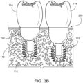
- Figures 3A and 3B compare the dental abutment 100 with a dental abutment 200 that has a length L 1 that is 0.24 inches ( ⁇ 6 mm).
- the dental abutment 100 and the abutment 200 have identical configurations except for the differences in the length L 1 .
- the dimensions of the post 120 are the same in both the dental abutment 100 and the abutment 200 such that a single type of dental implant can be used with either abutment.
- This configuration allows a dentist to set the position of the coronal portion 123 of the dental abutment 100, 200 relative to the gum above an implant regardless of the implant's axial position in the jawbone 112.
- Some dental abutments have retention elements 122 that have different perimeters (e.g., diameters for the illustrated dental abutments).
- Figures 4A and 4B compare the dental abutment 100 with a dental abutment 300 in which both length L1 and the diameter of the retention element are smaller than those of the dental abutment 100. It accommodates implant wells that are more parallel for greater retention or wider for greater strength and resistance to metal fatigue and breakage.
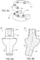
- FIG. 5A-5C show a system in which four dental abutments 100 are used to support a single dental prosthesis 114.
- dental abutments can be formed with the features described above but with the post set at angle relative to the coronal portion.
- Figures 6A and 6B show a dental abutment 400 in which an axis 124' of the post 120 set at angle relative to an axis 124" of the coronal portion 123.
Landscapes
- Health & Medical Sciences (AREA)
- Oral & Maxillofacial Surgery (AREA)
- Orthopedic Medicine & Surgery (AREA)
- Dentistry (AREA)
- Epidemiology (AREA)
- Life Sciences & Earth Sciences (AREA)
- Animal Behavior & Ethology (AREA)
- General Health & Medical Sciences (AREA)
- Public Health (AREA)
- Veterinary Medicine (AREA)
- Dental Prosthetics (AREA)
- Dental Preparations (AREA)
Description
- This application claims priority to
U.S. Application No. 14/591,654 entitled "Integrated Dental Implant Abutments," filed January 7, 2015 - The present disclosure concerns dental implant abutments.
- Dental implants are often the best treatment for missing teeth. When a damaged or decayed tooth is removed, both the visible part of the tooth, called the crown, and the root are lost.
- A dental implant can be placed in the jawbone so that it can be fused with natural bone and become a strong and sturdy foundation for replacement teeth. Implants can be used to replace an individual tooth or for an implant-supported bridge or denture containing multiple teeth.
- A dental implant abutment is a device that connects the prosthetic tooth/teeth to the dental implant. The replacement tooth is custom made to match a patient's natural teeth and is sometimes referred to as a crown or dental prosthesis.
-
US 2003/082499 describes components for an improved system for pick-up impression making at a dental implantation site, including an abutment, an abutment replica and an impression coping. -
US 6,290,500 describes an abutment that has a central portion between a post portion receivable in a dental implant and a head portion, the central portion has a hemispherical configuration. -
US 5,829,977 describes a two-piece abutment system, wherein the first part includes a tapering inner surface which is part of a bore extending entirely through the first part and the elongated second part includes a threaded stem for engaging a threaded bore with a dental implant and a post which extends above the first part. -
US 2004/063070 A1 describes an integrated abutment crown that has an abutment portion having a central hemispherical portion intermediate to a post portion receivable in the bore of an implant and a head portion which includes a nose and shelf extending from the outer circumference of the central portion to the nose. -
WO 2011/125309 A1 describes an implant capable of preventing force applied to an abutment from easily acting on an upper end portion of an implant fixture and as a result capable of suppressing ischemia in gums when used in a patient. - The invention is as defined by appended claims 1-9.
- This disclosure describes dental abutments that can not only be used for all conventional restorative techniques, but can also be readily scanned digitally, which enables precise restorations of a tooth or teeth to be fashioned more easily and conveniently than abutments whose geometry preclude the use of digital scanning or require modification or interpretation of scanned images for use. This feature supports the movement of the dental implant field toward precise customizable prosthetic restorations and digital dentistry with the increased use of CAD/CAM technologies.
- The dental abutment according to the invention includes anti-rotational features for the prosthetic component (i.e. crown) that allows the patient's prosthesis to have a precise fit. Grooves on opposite sides of the coronal end of the abutment (i.e. longitudinal end of abutment located farthest from the bone in the implanted site) provide the anti-rotation element. Each groove is generally of a constant depth that slopes toward the shoulder to end the anti-rotational element. The sloping of the groove is symmetric to reduce material stress. The coronal end of the abutment can also have a rough surface (e.g., a grit-blasted surface) to facilitate retention. For example, grit blasting can provide asperities up to 300 microns in size. The term "asperities" is used to indicate sharp, rough, or rugged projections extending from a surface.
- The described dental abutments have a post in the area of the apical end of the abutment (i.e. longitudinal end located closest to the bone in the implanted site) that is received by the open end of the dental implant. The post allows for a 360° of rotation during seating to increase the likelihood of correct orientation of the abutment, or abutment-restoration unit, either intra-orally or extra-orally. This 360° rotation also facilitates parallelism for angled abutments. The post and implant connection utilizes a friction fit connection which is a locking taper. Once fully engaged, this mechanism limits or prevents unintentional rotation between the dental abutment and implant and can provide a bacterially sealed connection. The post has a cylindrical shape for simplicity and compatibility with a large number of dental implants.
- Some dental abutments include a coronal portion that slopes to a shoulder of the dental abutment after a fixed distance of at least a 15° angle to allow for the scanning to be performed without any additional modifications or interpretations to the scan. The distance from the coronal end to the shoulder and the shoulder width has a ratio of less than seven with a shoulder width of greater than 0,51mm (0,02 inches). The team that developed the present dental abutments has found that the width of the shoulder and the ratio between the distance from the coronal end to the shoulder and the shoulder width to be particularly significant in providing an abutment that is conducive to digital scanning. The coronal portion slopes toward the shoulder of the dental abutment at about a 3° angle to allow the anti-rotational element to work properly.
- In some dental abutments, the distance from the bevel at the coronal end to the top of the hemispherical shoulder is long enough to allow all the edges of the dental abutment to be digitally scanned without additional modifications or interpretations. In contrast, other dental abutments have margins that are not smooth and/or not visible on scans so users manually draw in the margin on the scan results.
- The geometry of these dental abutments also allows for one conventional recording sleeve configuration to suffice for registering multiple different abutment dimensions, since different abutment sizes and angulations are independent of the prosthetic attachment aspect of the abutment. Conventional dental impression materials can be used to record and represent multiple different abutment dimensions prosthetically.
-
-
Figures 1A and1B show a dental implant and dental abutment before and after the addition of a crown, respectively. -
Figure 2A is a side view of a dental abutment.Figures 2B and 2C depict the cross section and coronal views of the abutment inFigure 2A , respectively. -
Figures 3A and3B show two dental abutments of different sizes with and without a crown. -
Figures 4A and4B show two dental abutments of different configurations with and without a crown. -
Figures 5A - 5C show a dental prosthesis supported by multiple dental abutments. -
Figures 6A and 6B are, respectively, a front view and a side crosssectional view of an angled dental abutment. -
Figure 1A shows adental abutment 100 engaged in adental implant 110 which has been placed in a patient'sjawbone 112.Figure 1B shows thedental abutment 100 and thedental implant 110 after acrown 114 has been placed on thedental abutment 100. - The
dental abutment 100 inFigure 1A extends from the apical end 116 (i.e. toward the jaw) to the coronal end 118 (i.e. toward the crown) in the longitudinal direction. Thedental abutment 100 has apost 120, which is designed to be received by the open end of thedental implant 110. Thepost 120 extends from theapical end 116 of thedental abutment 100 to aretention element 122. Thedental abutment 100 also has a coronal portion (or head) 123 which designed to support thecrown 114. Thecoronal portion 123 extends from thecoronal end 118 of thedental abutment 100 to theretention element 122. - The
dental abutment 100 can be made out of a variety of materials, including titanium alloy or polyether ether ketone (PEEK). -
figures 2A-2C shows thedental abutment 100 in isolation to more clearly illustrate features of thedental abutment 100. - The
post 120 is substantially cylindrical, which allows for the 360° rotation of thedental abutment 100 while it is being seated into the dental implant 110 (seeFigures 1A and1B ) in order to facilitate a dentist's correct orientation of the prosthesis or crown 114 (seeFigure 1B ), either intra-orally or extra-orally. This cylindrical shape provides the opportunity for the prosthesis to be used to orient and initially seat the abutment in the well of the implant. The simplicity of the cylindrical shape affords for improved manufacturability and also makes thedental abutment 100 compatible with a number of different types of dental prostheses. While substantially cylindrical, thepost 120 is tapered to provide a friction fit connection which is a locking taper between thepost 120 and the dental implant 110 (seeFigures 1A and1B ). This configuration can facilitate seizing, galling or cold welding between thepost 120 and thedental implant 110. - Once fully engaged, this mechanism limits or prevents unintentional rotation and micro-movement between the
dental abutment 100 and dental implant 110 (seeFigures 1A and1B ). The locking taper can also provide a bacterial seal between the two components. The angle α between sides of thepost 120 and alongitudinal axis 124 of thedental abutment 100 is approximately 1.3°. Depending on the dental abutment variant, the angle between sides of thepost 120 and alongitudinal axis 124 of thedental abutment 100 is typically between 1.1° and 1.6°. The geometry of thedental abutment 100 is symmetrical along thelongitudinal axis 124. - The
retention element 122 extends from thepost 120 to thecoronal portion 123. Theretention element 122 has abase 128 and ashoulder 130 which meets the base 128 at amargin 132. The transition between the base 128 and thepost 120 is acurve 134 with a radius of curvature 136 (seeFigure 2B ) of approximately 5,1 mm (0.02 inches) In some dental abutments, the radius ofcurvature 136 is more or less than 5,1 mm (0.02 inches) (e.g., between 0,25 and 0,76 mm (0.01 and 0.03 inches)) which can reduce stress factors and resulting fractures. The surface of thebase 128 has a radius of curvature 138 (seeFigure 2B ) of approximately 2 mm (0.08 inches) In some dental abutments, the radius ofcurvature 138 is more or less than 2 mm (e.g., between 2 mm and 3,8 mm (0.08 and 0.15 inches)) The shape of thebase 128 provides for the consistent confrontation of what is an approximation of a hemispherical contour to tissues in the proximity to the periosteum. This confrontation in turn can stimulate osteoblastic activity and subsequent bone growth. - Between the hemisphere and the
shoulder 130, the side of the abutment extends for a length L1 to themargin 132. The perimeter (e.g., circumference) of the dental abutment increases at 1-2° in this portion of the dental abutment as distance from theapical end 116 of thedental abutment 100. In thedental abutment 100, the length L1 is 0.16 inches (4 mm). As discussed in more detail below with reference toFigures 3A and3B , some dental abutments are configured in which the length L1 is more or less than 0.16 inches (4 mm) (e.g., between 0.05 (1.3 mm) and 0.32 inches (8.1 mm)). This variability provides the opportunity to use the same inferior or post and superior or head contours on the abutment, while providing the flexibility to use with implants placed at different depths within the jaw bone. - The diameter of the dental abutment at the
margin 132 is 0.24 inches (6 mm). In some dental abutments, the diameter of the dental abutment at themargin 132 is more or less than 0.24 inches (6 mm) (e.g., between 0.16 inches (4 mm) and 0.31 inches (8 mm). - An angle β is defined between the
shoulder 130 and aplane 140 that is perpendicular to thelongitudinal axis 124. Indental abutment 100, the angle β is approximately 15°. In some dental abutments, the angle β is more or less than 15° (e.g., between 10° and 20°). It has been found that dental abutments in which the angle β is approximately 15° allow the scanning to be performed without any additional modifications or interpretations to the scan. - The
coronal portion 123 includes aneck 142, ananti-rotation portion 144, and abevel 146 at the coronal end of thedental abutment 100. Theneck 142 has a length L2. Theneck 142 is substantially cylindrical with sides that are substantially parallel to thelongitudinal axis 124 of thedental abutment 100. Some dental abutments have necks with other shapes such as, for example, with rectangular or octagonal (rather than circular) cross-sections. - In contrast, the
anti-rotation portion 144 of thecoronal portion 123 is tapered with a cone angle γ such that the perimeter (e.g., circumference) of thecoronal portion 123 at the coronal end of theanti-rotation portion 144 is smaller than the apical end of theanti-rotation portion 144. Indental abutment 100, the cone angle γ is approximately 3°. In some dental abutments, the angle γ is more or less than 3° (e.g., between 2.5° and 3.5°). It has been found that dental abutments in which the angle γ is more than 2.5° help enable scanning to be performed without any additional modifications or interpretations to the scan. - The surface of
coronal portion 123 can be either rough or smooth based on the individual needs dictated by the procedure. A roughened surface can be achieved, for example, through the use of grit blasting. This provides a better surface for the adhesion of dental materials, such as opaque (i.e., composite dental resin that is used to cover unsightly dentition), as well as thecrown 114 or prosthesis to thecoronal portion 123. In particular, the roughened surface can facilitate the mechanical retention of chemical bonding agents such as opaque layers of composite resins or prosthetic cementing agents. - The structure of the
coronal portion 123 provides thedental abutment 100 with a configuration that can be easily scanned. The perimeter (e.g., the circumference) of thedental abutment 100 increases monotonically from thecoronal end 118 to themargin 132 defined between the base 128 and the shoulder. The edge between thebevel 146 and theanti-rotation portion 144 is smaller than the edge betweenanti-rotation portion 144 and theneck 142. The edge between theanti-rotation portion 144 and theneck 142 is smaller thanmargin 132 between theneck 142 and thebase 128. As can be seen best inFigure 2C , theshoulder 130 is visible and clearly delineated which makes theshoulder 130 easy to record during digital scanning. In addition, the length L3 (from thebevel 146 to theneck 142 of the coronal portion 123) is long enough that when present in concert with angle γ, allows all the edges of the dental abutment to be observed with a digital scanner without additional modifications or interpretations to the scan. Unlike abutments whose geometry preclude the use of digital scanning or require modification or interpretations of scanned images for use, the abutments presented in this application allow for easy digital scanning which enables the rapid and precise restorations of a tooth or teeth. This feature supports movement of the dental implant field toward customizable restorations or prostheses and digital dentistry with the increased use of CAD/CAM technologies. - The geometry of these dental abutments not only facilitate their recording by digital scanning technologies, but also allows for a singular conventional recording sleeve configuration to suffice for registering multiple different abutment dimensions. Further conventional dental impression materials can be used to record and represent their multiple different abutment dimensions prosthetically.
- The
anti-rotation portion 144 of thecoronal portion 123 includes antirotation features in the form of twogrooves 148 on opposite sides of thecoronal end 118. The anti-rotational features help control the orientation of a prosthetic component orcrown 114 which helps provide a precise fit of the prosthesis. The grooves also guide the prosthetic component orcrown 114 into the correct orientation. - The
anti-rotation grooves 148 located on opposite sides of thecoronal end 118 of thedental abutment 100 are generally of a constant depth that slopes toward the shoulder to end the anti-rotational element. The sloping of the groove is symmetric to reduce material stress. - The length L3 (see
Figure 2A ) of theanti-rotation portion 144 and thegrooves 148 are nominally 0.125 inches (3.2 mm). The width W (seeFigure 2A ) of thegrooves 148 is nominally 0.055 inches (1.4 mm). The depth D (seeFigure 2B ) of thegrooves 148 is nominally 0.02 inches (0.51 mm). As discussed above, theanti-rotation portion 144 of thecoronal portion 123 is tapered with an angle γ of approximately 3°. The angled surface allows the anti-rotational element (e.g., grooves 148) to work properly. In addition, the sloping surface facilitates attaching other components as it is difficult to attach additional components to parallel surfaces, - Some dental abutments have
grooves 148 in which the length L3 is more or less than 0.125 inches (3.2 mm) (e.g., between 0.1 (2.5 mm) and 0.3 inches (7.6 mm)), the width W is more or less than 0.055 inches (1.4 mm) (e.g., between 0.04 inches (1 mm) and 0.06 inches (1.5 mm)), and/or the depth D is more or less than 0.02 inches (0.51 mm) (e.g., between 0.010 inches (0.254 mm) to 0.030 inches (0.76 mm)). Some dental abutments include other anti-rotation features such as, for example, hexagonal or multisided flat surfaces and/or a variety of slots or grooves. - As discussed above, some dental abutments are configured in which the length L1 (between the hemispherical portion of the
base 128 and the margin 132) is more or less than 0.16 inches (4 mm) (e.g., between 0.06 inches (1.5 mm) and 0.32 inches (8.1 mm)). -
Figures 3A and3B compare thedental abutment 100 with adental abutment 200 that has a length L1 that is 0.24 inches (~ 6 mm). Thedental abutment 100 and theabutment 200 have identical configurations except for the differences in the length L1. In particular, the dimensions of thepost 120 are the same in both thedental abutment 100 and theabutment 200 such that a single type of dental implant can be used with either abutment. This configuration allows a dentist to set the position of thecoronal portion 123 of thedental abutment jawbone 112. - Some dental abutments have
retention elements 122 that have different perimeters (e.g., diameters for the illustrated dental abutments).Figures 4A and4B compare thedental abutment 100 with adental abutment 300 in which both length L1 and the diameter of the retention element are smaller than those of thedental abutment 100. It accommodates implant wells that are more parallel for greater retention or wider for greater strength and resistance to metal fatigue and breakage. - This specification has described a dental prostheses system including versatile abutments with numerous advantages. Dentists may now make numerous uses and modifications of and departures from the specific embodiments and techniques disclosed herein without departing from the inventive concepts. For example, multiple dental abutments as described above can be used to support a single dental prosthesis.
Figures 5A-5C show a system in which fourdental abutments 100 are used to support a singledental prosthesis 114. In another example, dental abutments can be formed with the features described above but with the post set at angle relative to the coronal portion.Figures 6A and 6B show adental abutment 400 in which an axis 124' of thepost 120 set at angle relative to anaxis 124" of thecoronal portion 123. - There has been described novel apparatus and techniques in connection with dental implanting. It is evident that those skilled in the art may make numerous modifications of and departures from the specific apparatus and techniques herein disclosed without departing from the inventive concepts. Consequently, the invention is to be construed as embracing each and every novel concept and combination of concepts disclosed herein and limited only by the scope of the appended claims
Claims (9)
- A dental abutment (100) extending from an apical end to a coronal end along a longitudinal axis, the dental abutment (100) comprising:a retention element (122) with a base oriented towards the apical end of the dental abutment (100) and a shoulder (130) oriented towards the coronal end of the dental abutment, the shoulder (130) oriented at an angle of at least 12.5° relative to a plane that is perpendicular to the longitudinal axis such that the perimeter of the retention element (122) increases with increasing distance from the coronal end of the dental abutment (100) through the region of the shoulder (130),wherein the base (128) comprises a hemispherical portion and a portion disposed between the hemispherical portion and the shoulder (130) of the retention element (122), the portion having a circumference that increases between 1° and 2° from an apical end of the portion;a post (120) extending from the apical end of the dental abutment (100)to the base of the retention element (122); anda head (123) extending from the coronal end of the dental abutment (100) to the shoulder (130) of the retention element (122), the head having a cone angle between 2.5° and 3.5°, wherein the head (123) defines two anti-rotational grooves (148) on diametrically opposite sides on the coronal end.
- The dental abutment (100) of claim 1, wherein each groove (148) extends from the coronal end towards the apical end and is configured to receive a securing element on a prosthesis which has a conical support face.
- The dental abutment (100) of claim 1, wherein the post (120) has an apical taper angle between 1.1° and 1.6°.
- The dental abutment (100) of claim 1, wherein the angle of the shoulder (130) relative to the plane that is perpendicular to the longitudinal axis is greater than 15°.
- The dental abutment (100) of claim 1, wherein a perimeter taken in a plane perpendicular to the longitudinal axis increases monotonically from the coronal end to a margin defined between the base (128) and the shoulder (130).
- The dental abutment (100) of claim 5, wherein the head comprises a bevel at the coronal end, a cylindrical portion adjacent the retention element (122), and an angled portion extending between the bevel and the cylindrical portion.
- The dental abutment (100) of claim 6, wherein the angled portion has a length from the bevel to the cylindrical portion and a cone angle such that all edges of the dental abutment (100) can be seen when scanned from above.
- The dental abutment (100) of claim 1, wherein the dental abutment (100) provides an approximation of a hemispherical contour in the base of the retention element (122).
- The dental abutment (100) of claim 1, wherein the portion has a length between 1.3 mm and 8.1 mm.
Applications Claiming Priority (3)
| Application Number | Priority Date | Filing Date | Title |
|---|---|---|---|
| US14/591,654 US10098712B2 (en) | 2015-01-07 | 2015-01-07 | Integrated dental implant abutments |
| PCT/US2016/012520 WO2016112211A1 (en) | 2015-01-07 | 2016-01-07 | Integrated dental implant abutments |
| EP16735425.7A EP3242626B1 (en) | 2015-01-07 | 2016-01-07 | Integrated dental implant abutments |
Related Parent Applications (1)
| Application Number | Title | Priority Date | Filing Date |
|---|---|---|---|
| EP16735425.7A Division EP3242626B1 (en) | 2015-01-07 | 2016-01-07 | Integrated dental implant abutments |
Publications (3)
| Publication Number | Publication Date |
|---|---|
| EP3777754A1 EP3777754A1 (en) | 2021-02-17 |
| EP3777754B1 true EP3777754B1 (en) | 2023-06-07 |
| EP3777754C0 EP3777754C0 (en) | 2023-06-07 |
Family
ID=56285867
Family Applications (2)
| Application Number | Title | Priority Date | Filing Date |
|---|---|---|---|
| EP20188558.9A Active EP3777754B1 (en) | 2015-01-07 | 2016-01-07 | Integrated dental implant abutments |
| EP16735425.7A Active EP3242626B1 (en) | 2015-01-07 | 2016-01-07 | Integrated dental implant abutments |
Family Applications After (1)
| Application Number | Title | Priority Date | Filing Date |
|---|---|---|---|
| EP16735425.7A Active EP3242626B1 (en) | 2015-01-07 | 2016-01-07 | Integrated dental implant abutments |
Country Status (4)
| Country | Link |
|---|---|
| US (2) | US10098712B2 (en) |
| EP (2) | EP3777754B1 (en) |
| ES (2) | ES2819798T3 (en) |
| WO (1) | WO2016112211A1 (en) |
Families Citing this family (4)
| Publication number | Priority date | Publication date | Assignee | Title |
|---|---|---|---|---|
| US20190053881A1 (en) * | 2017-08-16 | 2019-02-21 | Global Dental Science, LLC | Bar manufacturing and denture reference and registration system |
| EP3747394A1 (en) * | 2019-06-04 | 2020-12-09 | VITA-ZAHNFABRIK H. Rauter GmbH & Co. KG | Dental implant with different surface rawness |
| HU5207U (en) * | 2020-05-29 | 2020-10-28 | Toth Peter Dr | Angled two-portion monoblock dental implant |
| IL300098B2 (en) * | 2023-01-22 | 2024-09-01 | Krausz Ronen | Fixation fastener system for dental appliance |
Citations (7)
| Publication number | Priority date | Publication date | Assignee | Title |
|---|---|---|---|---|
| US20020127517A1 (en) * | 2001-03-09 | 2002-09-12 | Morgan Vincent J. | Method and apparatus for replicating the position of intra-osseous implants and abutments relative to analogs thereof |
| WO2003047455A1 (en) * | 2001-12-03 | 2003-06-12 | Cottrell Richard D | Modified dental implant fixture |
| US20040063070A1 (en) * | 2002-09-16 | 2004-04-01 | Morgan Vincent J. | Dental implant system and method |
| WO2006035011A1 (en) * | 2004-09-27 | 2006-04-06 | Heraeus Kulzer Gmbh | Ceramic enossal tooth implant |
| WO2008103908A1 (en) * | 2007-02-22 | 2008-08-28 | Debbie, Llc | Integrated dental abutment block |
| EP1419746B1 (en) * | 2002-11-13 | 2011-06-22 | Biomet 3i, LLC | Dental implant system |
| WO2011125309A1 (en) * | 2010-04-07 | 2011-10-13 | 有限会社シエスタ | Dental implant |
Family Cites Families (15)
| Publication number | Priority date | Publication date | Assignee | Title |
|---|---|---|---|---|
| US5527182A (en) * | 1993-12-23 | 1996-06-18 | Adt Advanced Dental Technologies, Ltd. | Implant abutment systems, devices, and techniques |
| US5989026A (en) * | 1995-05-25 | 1999-11-23 | Implant Innovations, Inc. | Ceramic two-piece dental abutment |
| US5829977A (en) * | 1995-05-25 | 1998-11-03 | Implant Innovations, Inc. | Two-piece dental abutment |
| US6290500B1 (en) | 1997-12-10 | 2001-09-18 | Diro, Inc. | Dental implant system and method |
| AU1811399A (en) * | 1997-12-10 | 1999-06-28 | Diro, Inc. | Temporary implant components, system and method |
| US6159010A (en) * | 1998-04-23 | 2000-12-12 | Implant Innovations, Inc. | Fenestrated dental coping |
| US6672871B2 (en) * | 2000-06-19 | 2004-01-06 | Nobel Biocare Ab | Coping with standoffs |
| US6951460B2 (en) | 2001-11-01 | 2005-10-04 | Astra Tech Ab | Components and method for improved impression making |
| US20050244789A1 (en) | 2004-04-30 | 2005-11-03 | Crohin Constant C | Aesthetic dental implant fixture and abutment system |
| US20090317769A1 (en) * | 2006-11-14 | 2009-12-24 | Urdaneta Rainier A | Resilient coping for immediate loading of dental implants |
| WO2010056330A1 (en) * | 2008-11-13 | 2010-05-20 | Robert Zena | Soft tissue models and methods of making for dental applications |
| EP2218423B1 (en) | 2009-02-12 | 2012-05-02 | Straumann Holding AG | Determining position and orientation of a dental implant |
| US20110229850A1 (en) | 2010-03-18 | 2011-09-22 | Bretton Joseph N | Dental coping and assembly with aligning anti-rotation feature |
| US20110306014A1 (en) * | 2010-06-11 | 2011-12-15 | Conte Gregory J | Components, Systems and Related Methods for Temporary Prosthetics |
| WO2012021256A2 (en) * | 2010-08-10 | 2012-02-16 | Exxonmobil Chemical Patents Inc. | Methane conversion process |
-
2015
- 2015-01-07 US US14/591,654 patent/US10098712B2/en active Active
-
2016
- 2016-01-07 EP EP20188558.9A patent/EP3777754B1/en active Active
- 2016-01-07 EP EP16735425.7A patent/EP3242626B1/en active Active
- 2016-01-07 ES ES16735425T patent/ES2819798T3/en active Active
- 2016-01-07 ES ES20188558T patent/ES2953129T3/en active Active
- 2016-01-07 WO PCT/US2016/012520 patent/WO2016112211A1/en active Application Filing
-
2018
- 2018-10-15 US US16/160,752 patent/US20190151052A1/en active Pending
Patent Citations (7)
| Publication number | Priority date | Publication date | Assignee | Title |
|---|---|---|---|---|
| US20020127517A1 (en) * | 2001-03-09 | 2002-09-12 | Morgan Vincent J. | Method and apparatus for replicating the position of intra-osseous implants and abutments relative to analogs thereof |
| WO2003047455A1 (en) * | 2001-12-03 | 2003-06-12 | Cottrell Richard D | Modified dental implant fixture |
| US20040063070A1 (en) * | 2002-09-16 | 2004-04-01 | Morgan Vincent J. | Dental implant system and method |
| EP1419746B1 (en) * | 2002-11-13 | 2011-06-22 | Biomet 3i, LLC | Dental implant system |
| WO2006035011A1 (en) * | 2004-09-27 | 2006-04-06 | Heraeus Kulzer Gmbh | Ceramic enossal tooth implant |
| WO2008103908A1 (en) * | 2007-02-22 | 2008-08-28 | Debbie, Llc | Integrated dental abutment block |
| WO2011125309A1 (en) * | 2010-04-07 | 2011-10-13 | 有限会社シエスタ | Dental implant |
Also Published As
| Publication number | Publication date |
|---|---|
| EP3242626A1 (en) | 2017-11-15 |
| WO2016112211A1 (en) | 2016-07-14 |
| US20160193016A1 (en) | 2016-07-07 |
| EP3242626B1 (en) | 2020-08-05 |
| EP3242626A4 (en) | 2018-08-29 |
| US10098712B2 (en) | 2018-10-16 |
| EP3777754A1 (en) | 2021-02-17 |
| ES2953129T3 (en) | 2023-11-08 |
| ES2819798T3 (en) | 2021-04-19 |
| US20190151052A1 (en) | 2019-05-23 |
| EP3777754C0 (en) | 2023-06-07 |
Similar Documents
| Publication | Publication Date | Title |
|---|---|---|
| US11202693B2 (en) | Dental implant abutment copings | |
| US8246870B2 (en) | Dental implant system and method of use | |
| US20190151052A1 (en) | Integrated Dental Implant Abutments | |
| CA2044927C (en) | Implant collar and post system | |
| US20120171638A1 (en) | Holding piece for an implant | |
| US10149741B2 (en) | Method of attaching a dental component to a dental implant | |
| US20110306014A1 (en) | Components, Systems and Related Methods for Temporary Prosthetics | |
| RU2657848C2 (en) | Dental orthopedic construction for the implant | |
| US20040265781A1 (en) | Dental implant method & apparatus | |
| ES2529350T3 (en) | Abutment set for a dental implant and manufacturing method of a dental prosthesis | |
| US20030087217A1 (en) | Dental implant method & apparatus | |
| JP5052342B2 (en) | Dental implant system and kit | |
| US20150173864A1 (en) | Abutment assembly for dental implants | |
| US9877809B2 (en) | Abutment system for immediate implants for producing a dental prosthesis | |
| ES2849725T3 (en) | Cemented dental prostheses on implants and / or abutments that have an inverted edge | |
| US9149347B2 (en) | Abutment for a dental implant | |
| KR101909323B1 (en) | Dental implant | |
| US20160324602A1 (en) | Abutment system for immediate implants |
Legal Events
| Date | Code | Title | Description |
|---|---|---|---|
| PUAI | Public reference made under article 153(3) epc to a published international application that has entered the european phase |
Free format text: ORIGINAL CODE: 0009012 |
|
| STAA | Information on the status of an ep patent application or granted ep patent |
Free format text: STATUS: THE APPLICATION HAS BEEN PUBLISHED |
|
| AC | Divisional application: reference to earlier application |
Ref document number: 3242626 Country of ref document: EP Kind code of ref document: P |
|
| AK | Designated contracting states |
Kind code of ref document: A1 Designated state(s): AL AT BE BG CH CY CZ DE DK EE ES FI FR GB GR HR HU IE IS IT LI LT LU LV MC MK MT NL NO PL PT RO RS SE SI SK SM TR |
|
| STAA | Information on the status of an ep patent application or granted ep patent |
Free format text: STATUS: REQUEST FOR EXAMINATION WAS MADE |
|
| 17P | Request for examination filed |
Effective date: 20210301 |
|
| RBV | Designated contracting states (corrected) |
Designated state(s): AL AT BE BG CH CY CZ DE DK EE ES FI FR GB GR HR HU IE IS IT LI LT LU LV MC MK MT NL NO PL PT RO RS SE SI SK SM TR |
|
| GRAP | Despatch of communication of intention to grant a patent |
Free format text: ORIGINAL CODE: EPIDOSNIGR1 |
|
| STAA | Information on the status of an ep patent application or granted ep patent |
Free format text: STATUS: GRANT OF PATENT IS INTENDED |
|
| INTG | Intention to grant announced |
Effective date: 20221102 |
|
| GRAS | Grant fee paid |
Free format text: ORIGINAL CODE: EPIDOSNIGR3 |
|
| GRAA | (expected) grant |
Free format text: ORIGINAL CODE: 0009210 |
|
| STAA | Information on the status of an ep patent application or granted ep patent |
Free format text: STATUS: THE PATENT HAS BEEN GRANTED |
|
| AC | Divisional application: reference to earlier application |
Ref document number: 3242626 Country of ref document: EP Kind code of ref document: P |
|
| AK | Designated contracting states |
Kind code of ref document: B1 Designated state(s): AL AT BE BG CH CY CZ DE DK EE ES FI FR GB GR HR HU IE IS IT LI LT LU LV MC MK MT NL NO PL PT RO RS SE SI SK SM TR |
|
| REG | Reference to a national code |
Ref country code: GB Ref legal event code: FG4D |
|
| REG | Reference to a national code |
Ref country code: CH Ref legal event code: EP Ref country code: AT Ref legal event code: REF Ref document number: 1572532 Country of ref document: AT Kind code of ref document: T Effective date: 20230615 Ref country code: DE Ref legal event code: R096 Ref document number: 602016080269 Country of ref document: DE |
|
| U01 | Request for unitary effect filed |
Effective date: 20230628 |
|
| U07 | Unitary effect registered |
Designated state(s): AT BE BG DE DK EE FI FR IT LT LU LV MT NL PT SE SI Effective date: 20230704 |
|
| REG | Reference to a national code |
Ref country code: LT Ref legal event code: MG9D |
|
| PG25 | Lapsed in a contracting state [announced via postgrant information from national office to epo] |
Ref country code: NO Free format text: LAPSE BECAUSE OF FAILURE TO SUBMIT A TRANSLATION OF THE DESCRIPTION OR TO PAY THE FEE WITHIN THE PRESCRIBED TIME-LIMIT Effective date: 20230907 |
|
| REG | Reference to a national code |
Ref country code: ES Ref legal event code: FG2A Ref document number: 2953129 Country of ref document: ES Kind code of ref document: T3 Effective date: 20231108 |
|
| PG25 | Lapsed in a contracting state [announced via postgrant information from national office to epo] |
Ref country code: RS Free format text: LAPSE BECAUSE OF FAILURE TO SUBMIT A TRANSLATION OF THE DESCRIPTION OR TO PAY THE FEE WITHIN THE PRESCRIBED TIME-LIMIT Effective date: 20230607 Ref country code: HR Free format text: LAPSE BECAUSE OF FAILURE TO SUBMIT A TRANSLATION OF THE DESCRIPTION OR TO PAY THE FEE WITHIN THE PRESCRIBED TIME-LIMIT Effective date: 20230607 Ref country code: GR Free format text: LAPSE BECAUSE OF FAILURE TO SUBMIT A TRANSLATION OF THE DESCRIPTION OR TO PAY THE FEE WITHIN THE PRESCRIBED TIME-LIMIT Effective date: 20230908 |
|
| PG25 | Lapsed in a contracting state [announced via postgrant information from national office to epo] |
Ref country code: SK Free format text: LAPSE BECAUSE OF FAILURE TO SUBMIT A TRANSLATION OF THE DESCRIPTION OR TO PAY THE FEE WITHIN THE PRESCRIBED TIME-LIMIT Effective date: 20230607 |
|
| PG25 | Lapsed in a contracting state [announced via postgrant information from national office to epo] |
Ref country code: IS Free format text: LAPSE BECAUSE OF FAILURE TO SUBMIT A TRANSLATION OF THE DESCRIPTION OR TO PAY THE FEE WITHIN THE PRESCRIBED TIME-LIMIT Effective date: 20231007 |
|
| PG25 | Lapsed in a contracting state [announced via postgrant information from national office to epo] |
Ref country code: SM Free format text: LAPSE BECAUSE OF FAILURE TO SUBMIT A TRANSLATION OF THE DESCRIPTION OR TO PAY THE FEE WITHIN THE PRESCRIBED TIME-LIMIT Effective date: 20230607 Ref country code: SK Free format text: LAPSE BECAUSE OF FAILURE TO SUBMIT A TRANSLATION OF THE DESCRIPTION OR TO PAY THE FEE WITHIN THE PRESCRIBED TIME-LIMIT Effective date: 20230607 Ref country code: RO Free format text: LAPSE BECAUSE OF FAILURE TO SUBMIT A TRANSLATION OF THE DESCRIPTION OR TO PAY THE FEE WITHIN THE PRESCRIBED TIME-LIMIT Effective date: 20230607 Ref country code: IS Free format text: LAPSE BECAUSE OF FAILURE TO SUBMIT A TRANSLATION OF THE DESCRIPTION OR TO PAY THE FEE WITHIN THE PRESCRIBED TIME-LIMIT Effective date: 20231007 Ref country code: CZ Free format text: LAPSE BECAUSE OF FAILURE TO SUBMIT A TRANSLATION OF THE DESCRIPTION OR TO PAY THE FEE WITHIN THE PRESCRIBED TIME-LIMIT Effective date: 20230607 |
|
| PG25 | Lapsed in a contracting state [announced via postgrant information from national office to epo] |
Ref country code: PL Free format text: LAPSE BECAUSE OF FAILURE TO SUBMIT A TRANSLATION OF THE DESCRIPTION OR TO PAY THE FEE WITHIN THE PRESCRIBED TIME-LIMIT Effective date: 20230607 |
|
| REG | Reference to a national code |
Ref country code: DE Ref legal event code: R097 Ref document number: 602016080269 Country of ref document: DE |
|
| PLBE | No opposition filed within time limit |
Free format text: ORIGINAL CODE: 0009261 |
|
| STAA | Information on the status of an ep patent application or granted ep patent |
Free format text: STATUS: NO OPPOSITION FILED WITHIN TIME LIMIT |
|
| 26N | No opposition filed |
Effective date: 20240308 |
|
| PG25 | Lapsed in a contracting state [announced via postgrant information from national office to epo] |
Ref country code: MC Free format text: LAPSE BECAUSE OF FAILURE TO SUBMIT A TRANSLATION OF THE DESCRIPTION OR TO PAY THE FEE WITHIN THE PRESCRIBED TIME-LIMIT Effective date: 20230607 |
|
| PG25 | Lapsed in a contracting state [announced via postgrant information from national office to epo] |
Ref country code: MC Free format text: LAPSE BECAUSE OF FAILURE TO SUBMIT A TRANSLATION OF THE DESCRIPTION OR TO PAY THE FEE WITHIN THE PRESCRIBED TIME-LIMIT Effective date: 20230607 |
|
| REG | Reference to a national code |
Ref country code: CH Ref legal event code: PL |
|
| U90 | Patent deemed lapsed [failed payment of renewal/compensation fee, unitary effect] |
Free format text: RENEWAL FEE NOT PAID FOR YEAR NN Effective date: 20240814 |
|
| GBPC | Gb: european patent ceased through non-payment of renewal fee |
Effective date: 20240107 |
|
| PG25 | Lapsed in a contracting state [announced via postgrant information from national office to epo] |
Ref country code: GB Free format text: LAPSE BECAUSE OF NON-PAYMENT OF DUE FEES Effective date: 20240107 |