EP3777744A1 - Catheter with coaxial thermocouple - Google Patents
Catheter with coaxial thermocouple Download PDFInfo
- Publication number
- EP3777744A1 EP3777744A1 EP20192188.9A EP20192188A EP3777744A1 EP 3777744 A1 EP3777744 A1 EP 3777744A1 EP 20192188 A EP20192188 A EP 20192188A EP 3777744 A1 EP3777744 A1 EP 3777744A1
- Authority
- EP
- European Patent Office
- Prior art keywords
- layer
- core
- medical device
- distal end
- coaxial
- Prior art date
- Legal status (The legal status is an assumption and is not a legal conclusion. Google has not performed a legal analysis and makes no representation as to the accuracy of the status listed.)
- Withdrawn
Links
- 0 CC1*CCC1 Chemical compound CC1*CCC1 0.000 description 1
Images




Classifications
-
- A—HUMAN NECESSITIES
- A61—MEDICAL OR VETERINARY SCIENCE; HYGIENE
- A61B—DIAGNOSIS; SURGERY; IDENTIFICATION
- A61B18/00—Surgical instruments, devices or methods for transferring non-mechanical forms of energy to or from the body
- A61B18/04—Surgical instruments, devices or methods for transferring non-mechanical forms of energy to or from the body by heating
- A61B18/12—Surgical instruments, devices or methods for transferring non-mechanical forms of energy to or from the body by heating by passing a current through the tissue to be heated, e.g. high-frequency current
- A61B18/14—Probes or electrodes therefor
- A61B18/1492—Probes or electrodes therefor having a flexible, catheter-like structure, e.g. for heart ablation
-
- A—HUMAN NECESSITIES
- A61—MEDICAL OR VETERINARY SCIENCE; HYGIENE
- A61B—DIAGNOSIS; SURGERY; IDENTIFICATION
- A61B18/00—Surgical instruments, devices or methods for transferring non-mechanical forms of energy to or from the body
- A61B18/04—Surgical instruments, devices or methods for transferring non-mechanical forms of energy to or from the body by heating
- A61B18/12—Surgical instruments, devices or methods for transferring non-mechanical forms of energy to or from the body by heating by passing a current through the tissue to be heated, e.g. high-frequency current
-
- B—PERFORMING OPERATIONS; TRANSPORTING
- B21—MECHANICAL METAL-WORKING WITHOUT ESSENTIALLY REMOVING MATERIAL; PUNCHING METAL
- B21C—MANUFACTURE OF METAL SHEETS, WIRE, RODS, TUBES, PROFILES OR LIKE SEMI-MANUFACTURED PRODUCTS OTHERWISE THAN BY ROLLING; AUXILIARY OPERATIONS USED IN CONNECTION WITH METAL-WORKING WITHOUT ESSENTIALLY REMOVING MATERIAL
- B21C1/00—Manufacture of metal sheets, wire, rods, tubes or like semi-manufactured products by drawing
-
- G—PHYSICS
- G01—MEASURING; TESTING
- G01K—MEASURING TEMPERATURE; MEASURING QUANTITY OF HEAT; THERMALLY-SENSITIVE ELEMENTS NOT OTHERWISE PROVIDED FOR
- G01K13/00—Thermometers specially adapted for specific purposes
- G01K13/10—Thermometers specially adapted for specific purposes for measuring temperature within piled or stacked materials
-
- G—PHYSICS
- G01—MEASURING; TESTING
- G01K—MEASURING TEMPERATURE; MEASURING QUANTITY OF HEAT; THERMALLY-SENSITIVE ELEMENTS NOT OTHERWISE PROVIDED FOR
- G01K13/00—Thermometers specially adapted for specific purposes
- G01K13/20—Clinical contact thermometers for use with humans or animals
-
- G—PHYSICS
- G01—MEASURING; TESTING
- G01K—MEASURING TEMPERATURE; MEASURING QUANTITY OF HEAT; THERMALLY-SENSITIVE ELEMENTS NOT OTHERWISE PROVIDED FOR
- G01K7/00—Measuring temperature based on the use of electric or magnetic elements directly sensitive to heat ; Power supply therefor, e.g. using thermoelectric elements
- G01K7/02—Measuring temperature based on the use of electric or magnetic elements directly sensitive to heat ; Power supply therefor, e.g. using thermoelectric elements using thermoelectric elements, e.g. thermocouples
-
- G—PHYSICS
- G01—MEASURING; TESTING
- G01K—MEASURING TEMPERATURE; MEASURING QUANTITY OF HEAT; THERMALLY-SENSITIVE ELEMENTS NOT OTHERWISE PROVIDED FOR
- G01K7/00—Measuring temperature based on the use of electric or magnetic elements directly sensitive to heat ; Power supply therefor, e.g. using thermoelectric elements
- G01K7/02—Measuring temperature based on the use of electric or magnetic elements directly sensitive to heat ; Power supply therefor, e.g. using thermoelectric elements using thermoelectric elements, e.g. thermocouples
- G01K7/04—Measuring temperature based on the use of electric or magnetic elements directly sensitive to heat ; Power supply therefor, e.g. using thermoelectric elements using thermoelectric elements, e.g. thermocouples the object to be measured not forming one of the thermoelectric materials
- G01K7/06—Measuring temperature based on the use of electric or magnetic elements directly sensitive to heat ; Power supply therefor, e.g. using thermoelectric elements using thermoelectric elements, e.g. thermocouples the object to be measured not forming one of the thermoelectric materials the thermoelectric materials being arranged one within the other with the junction at one end exposed to the object, e.g. sheathed type
-
- H—ELECTRICITY
- H01—ELECTRIC ELEMENTS
- H01B—CABLES; CONDUCTORS; INSULATORS; SELECTION OF MATERIALS FOR THEIR CONDUCTIVE, INSULATING OR DIELECTRIC PROPERTIES
- H01B1/00—Conductors or conductive bodies characterised by the conductive materials; Selection of materials as conductors
- H01B1/02—Conductors or conductive bodies characterised by the conductive materials; Selection of materials as conductors mainly consisting of metals or alloys
- H01B1/026—Alloys based on copper
-
- H—ELECTRICITY
- H01—ELECTRIC ELEMENTS
- H01B—CABLES; CONDUCTORS; INSULATORS; SELECTION OF MATERIALS FOR THEIR CONDUCTIVE, INSULATING OR DIELECTRIC PROPERTIES
- H01B3/00—Insulators or insulating bodies characterised by the insulating materials; Selection of materials for their insulating or dielectric properties
- H01B3/02—Insulators or insulating bodies characterised by the insulating materials; Selection of materials for their insulating or dielectric properties mainly consisting of inorganic substances
- H01B3/12—Insulators or insulating bodies characterised by the insulating materials; Selection of materials for their insulating or dielectric properties mainly consisting of inorganic substances ceramics
-
- H—ELECTRICITY
- H01—ELECTRIC ELEMENTS
- H01B—CABLES; CONDUCTORS; INSULATORS; SELECTION OF MATERIALS FOR THEIR CONDUCTIVE, INSULATING OR DIELECTRIC PROPERTIES
- H01B7/00—Insulated conductors or cables characterised by their form
- H01B7/17—Protection against damage caused by external factors, e.g. sheaths or armouring
-
- A—HUMAN NECESSITIES
- A61—MEDICAL OR VETERINARY SCIENCE; HYGIENE
- A61B—DIAGNOSIS; SURGERY; IDENTIFICATION
- A61B18/00—Surgical instruments, devices or methods for transferring non-mechanical forms of energy to or from the body
- A61B2018/00053—Mechanical features of the instrument of device
- A61B2018/00059—Material properties
- A61B2018/00071—Electrical conductivity
- A61B2018/00077—Electrical conductivity high, i.e. electrically conducting
-
- A—HUMAN NECESSITIES
- A61—MEDICAL OR VETERINARY SCIENCE; HYGIENE
- A61B—DIAGNOSIS; SURGERY; IDENTIFICATION
- A61B18/00—Surgical instruments, devices or methods for transferring non-mechanical forms of energy to or from the body
- A61B2018/00053—Mechanical features of the instrument of device
- A61B2018/00059—Material properties
- A61B2018/00071—Electrical conductivity
- A61B2018/00083—Electrical conductivity low, i.e. electrically insulating
-
- A—HUMAN NECESSITIES
- A61—MEDICAL OR VETERINARY SCIENCE; HYGIENE
- A61B—DIAGNOSIS; SURGERY; IDENTIFICATION
- A61B18/00—Surgical instruments, devices or methods for transferring non-mechanical forms of energy to or from the body
- A61B2018/00315—Surgical instruments, devices or methods for transferring non-mechanical forms of energy to or from the body for treatment of particular body parts
- A61B2018/00345—Vascular system
- A61B2018/00351—Heart
-
- A—HUMAN NECESSITIES
- A61—MEDICAL OR VETERINARY SCIENCE; HYGIENE
- A61B—DIAGNOSIS; SURGERY; IDENTIFICATION
- A61B18/00—Surgical instruments, devices or methods for transferring non-mechanical forms of energy to or from the body
- A61B2018/00571—Surgical instruments, devices or methods for transferring non-mechanical forms of energy to or from the body for achieving a particular surgical effect
- A61B2018/00577—Ablation
-
- A—HUMAN NECESSITIES
- A61—MEDICAL OR VETERINARY SCIENCE; HYGIENE
- A61B—DIAGNOSIS; SURGERY; IDENTIFICATION
- A61B18/00—Surgical instruments, devices or methods for transferring non-mechanical forms of energy to or from the body
- A61B2018/00636—Sensing and controlling the application of energy
- A61B2018/00773—Sensed parameters
- A61B2018/00791—Temperature
- A61B2018/00821—Temperature measured by a thermocouple
Definitions
- This invention relates to catheters and electrophysiologic catheters, in particular, catheters for cardiac tissue ablation and diagnostics.
- Radiofrequency (RF) ablation of cardiac and other tissue is a well-known method for creating thermal injury lesions at the tip of an electrode.
- Radiofrequency current is delivered between a skin (ground) patch and the electrode, or between two electrodes.
- Electrical resistance at the electrode-tissue interface results in direct resistive heating of a small area, the size of which depends upon the size of the electrode, electrode tissue contact area, and current (density). Further tissue heating results from conduction of heat within the tissue to a larger zone. Tissue heated beyond a threshold of approximately 50-55 degrees C is irreversibly injured (ablated).
- Resistive heating is caused by energy absorption due to electrical resistance. Energy absorption is related to the square of current density and inversely with tissue conductivity. Current density varies with contact area conductivity, voltage and inversely with the square of the distance from the ablating electrode. Therefore, energy absorption varies with conductivity, the square of applied voltage, and inversely with the fourth power of the distance from the electrode. Resistive heating, therefore, is most heavily influenced by distance, and penetrates a very small distance from the ablating electrode. The rest of the lesion is created by thermal conduction from the area of resistive heating. This imposes a limit on the size of ablation lesions that can be delivered from a surface electrode.
- Theoretical methods to increase lesion size would include increasing electrode size, increasing the area of electrode contact with tissue, increasing tissue conductivity and penetrating the tissue to achieve greater depth and increase the area of contact, and delivering RF until maximal lesion size has been achieved (60-90 seconds for full maturation).
- the electrode can be introduced to the tissue of interest directly (for superficial/skin structures), surgically, endoscopically, laparoscopically or using percutaneous transvascular (catheter-based) access.
- Catheter ablation is a well-described and commonly performed method by which many cardiac arrhythmias are treated.
- Catheter ablation is sometimes limited by insufficient lesion size. Ablation of tissue from an endovascular approach results not only in heating of tissue, but heating of the electrode. When the electrode reaches critical temperatures, denaturation of blood proteins causes coagulum formation. Impedance can then rise and limit current delivery. Within tissue, overheating can cause steam bubble formation (steam "pops") with risk of uncontrolled tissue destruction or undesirable perforation of bodily structures. In cardiac ablation, clinical success is sometimes hampered by inadequate lesion depth and transverse diameter even when using catheters with active cooling of the tip.
- Theoretical solutions have included increasing the electrode size (increasing contact surface and increasing convective cooling by blood flow), improving electrode-tissue contact, actively cooling the electrode with fluid infusion, changing the material composition of the electrode to improve current delivery to tissue, and pulsing current delivery to allow intermittent cooling.
- thermocouple wire pair 80 and 82 that extend from the control handle, through the catheter shaft and into the distal section where a "hot" or temperature measuring junction H of the wire pair is positioned.
- the wire pair 80 and 82 are typically stripped of insulating cover 85, twisted, soldered and potted in a blind hole 86 formed in a distal tip electrode 84, as known in the art.
- thermocouple junction H the precise location of the distal end "hot" junction H within the blind hole 86 or relative to the tip electrode 84 is not known, even though the depth of the blind hole 86 may be known.
- An alternate method of assembly includes laser stripping the insulation of a small area of the bifilar wire and then soldering the wires together in that location. Both methods of forming a thermocouple junction are limited in their ability to form a junction at the very bottom of a blind hole. The exact location of the thermocouple junction is the proximal location where the wires are electrically connected.
- the location where the temperature is actually measured is by design limited to at least the axial length of the solder joint.
- there is a desire for a catheter with a temperature sensor where a more precise location is known of where the temperature is being sensed.
- the conventional thermocouple wire pair has an awkward profile, as shown in FIG. 3C , which can often split or tear between the two wires.
- thermocouple wire pair having a more precise location of its "hot" junction, an improved profile, a more durable construction, and an easier method of assembly.
- the present invention is directed to a temperature sensor having a more precise temperature sensing location.
- the temperature sensor includes a coaxial thermocouple wire pair having a more precise "hot" junction at which a first and second metallic material electrically connect with each other for measuring temperature.
- the present invention includes a temperature sensing tensile member for use with a medical device, for example, an electrophysiologic catheter, comprising an elongated body having a proximal end and a distal end.
- the body includes a core of a first metallic material, the core defining a longitudinal axis, a first coaxial layer of insulating material circumferentially surrounding the core, and a second coaxial layer of a second metallic material circumferentially surrounding the first layer, the second metallic material being different from the first metallic material, the first layer of insulating material electrically insulating the core and second layer from each other along the length of the body and a second layer of insulating material surrounding the assembly and electrically insulating the assembly from the environment.
- the member further including a solder cap on the distal end, the solder cap electrically connecting the core and the second layer at the distal end.
- the core includes constantan and the second layer includes copper, or vice versa, and the insulating material includes ceramic and/or a polymer.
- the member further comprises an outer protective sheath that is electrically nonconductive.
- the body has been drawn through a die.
- the present invention is also directed to an electrophysiologic catheter comprising an elongated catheter body, a distal electrode member, and a temperature sensor having a tensile body, the tensile body extending through the catheter body and having at least a distal end received in the distal electrode member.
- the temperature sensor comprising a core of a first metallic material defining a longitudinal axis, a coaxial insulating material circumferentially surrounding the core, a coaxial layer of a second metallic material circumferentially surrounding the insulating material, a coaxial insulating material circumferentially surrounding the assembly; and a solder cap on the distal end of the tensile body, the solder cap electrically connecting the core and the layer.
- the body has been drawn through a die and the coaxial insulating material includes ceramic particulates.
- the present invention further includes a method of manufacturing a coaxial thermocouple wire pair member adapted for use with an electrophysiologic catheter, comprising providing a core of a first metallic material defining a longitudinal axis, coaxially surrounding the core with an insulating ceramic material, coaxially surrounding the insulating material with a second metallic material different from the first metallic material, drawing the member through a die, insulating the assembly with a polymer coating, and applying solder on a distal end of the member to electrically connecting the core and the layer at the distal end.
- the method includes trimming the distal end to expose the core and the layer after drawing the member through a die and before applying solder on the distal end.
- a drawn thermocouple coaxial wire pair member 10 of the present invention includes a single elongated tensile body 12 with a generally circular cross-section.
- the member 10 has an electrically-conductive core 14 defining a longitudinal axis of the body 12.
- the core 14 includes a metallic material as a first wire of the wire pair.
- the member 10 also has an electrically-conductive coaxial layer 16 that includes a different or dissimilar metallic material as a second wire of the wire pair.
- extending along the length of the body 12, between the metallic core 14 and the metallic layer 16 is an electrically insulating layer 18 that surrounds the core 14 and separates and isolates it from the layer 16.
- the core 14 and the metallic layer 16 may be of any suitable metals, including, for example, constantan and copper, or vice versa.
- the insulating layer 18 may be of any suitable material, including, for example, ceramic.
- An electrically insulating outer sheath 26 may be provided over the entirety of the member. With a coaxial construction providing a generally circular cross-section, as shown in FIG. 2B , the member 10 has an improved profile in terms of utility, convenience and aesthetics.
- the metallic materials for the first and second wires of the member 10 may be copper and constantan, or vice versa. Alternately, they may be any other dissimilar metals that form a thermocouple.
- the insulating layer 18 may be constructed of any suitable material, including, for example, a polymer and/or ceramic.
- the insulating sheath 26 may be constructed of any suitable material, including, for example, a polymer. The preferred method of applying sheath 26 would be a film casting method used to insulate magnet wires, as shown in the
- distal end 12D of the member 10 has a solder cap 20D of a filler metal forming a distal junction of a circuit C between the core 14 and the layer 16.
- the distal solder cap 20D is adapted for measuring temperature of tissue.
- the two conductive layers are attached to wires of corresponding material, as shown in FIG. 2C . This can be accomplished by grinding the sheath 26, and the layers 16, and 18 off proximal end 12P of the member 10 (as shown in broken lines) to expose the core 14. Distally to this grinding, the sheath 26 can be removed mechanically or thermally to expose the layer 16.
- the layers 14 and 16 can be soldered to a circuit or have wires W1 and W2 of corresponding material soldered directly to them at 20P1 and 20P2, respectively.
- the solders 20P1 and 20P2 used for this attachment and the distal solder cap 20D can be any solder preferred by the industry, but are usually primarily comprised of tin.
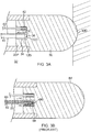
- a catheter distal tip 32 includes a distal tip electrode 30 having a distal end 30D adapted for contact with tissue for diagnostic and/or therapeutic procedures by means of a lead wire 40 whose distal end is anchored and potted in a blind hole 42.
- the tip electrode 30 also has a proximal end 30P whose face is configured with a blind hole 34 for receiving the distal end 12D and solder cap 20D of the thermocouple wire pair member 10 of the present invention.
- the blind hole 34 has predetermined and known depth X at an end or "bottom" 36 at which the distal solder cap 20D is placed and potted linearly without any bends or folds in the portion of the member 10 in the hole 34.
- the precise location of the distal solder cap 20D (the "hot junction") is known relative to the distal tip electrode when temperature is measured by the member 10 at the distal tip electrode 30.
- the member 10 extends through a catheter 60 from the distal tip 32, through a catheter shaft 62 (with a deflection section 64) into a control handle 66 where it is connected to an electrical connector 68 at the proximal end of the handle, as shown in FIG. 4 .
- one or more members 10 may be used with any distal electrode assembly, whether the assembly has a 2-D configuration of a 3-D configuration, for example, circular-, lasso-, basket- or spine-type catheter.
- thermocouple wire pair member 10 includes a method of manufacturing a thermocouple wire pair member 10.
- the thermocouple wire pair first may be shapened by drawing processes owned and practiced by Fort Wayne Metals Research Products Corporation (Fort Wayne, Indiana), a manufacturer of precision wire-based materials for medical and industrial applications.
- a layered (predrawn) member 10' includes the elongated solid core 14 of a first metallic material which is surrounded circumferentially by a layer of insulating material (e.g., ceramic) forming the insulating layer 18.
- the core 14 and the layer 18 are surrounded circumferentially by a layer of a second metallic material dissimilar to the first metallic material of the core, forming the outer layer 16.
- the member 10' may be assembled with the core 14 configured as a solid rod that is inserted into a first, inner hollow tube as the layer 18, and then together into a second, outer hollow tube as the layer 16.
- the member 10' as described above, having an original outer diameter D1 is passed through a die 50 adapted to receive an end of the member 10' to draw it into desired shape and size, including a resulting drawn smaller outer diameter D2.
- a die holder 52 is provided to hold the die 50.
- the drawing process may be "cold” or “hot” drawn as desired or appropriate.
- the member 10' may be pushed and/or pulled through the die 50, as known in the art.
- any or all of the core 14 and the layers 16, and 18 are reshapened, for example, thinned and stretched into the drawn member 10.
- the insulating layer 18 is ceramic
- the ceramic is crushed or otherwise broken into smaller particles. After repeated drawing, the ceramic may be crushed into powder form 44.
- the drawing process would be for multiple thousands of feet at a time.
- the formed member comprising the core 14 and the layers 18, and 16 can then be run through a multiple layer coating process, i.e. film cast, to apply an insulating polymer layer to the outside.
- the distal end 12D is prepared for a solder cap by being trimmed to expose the core 14 and the layer 16, and dipped in solder to form distal solder cap 20D, as shown i FIG. 2A .
- the distal solder cap 20D does not extend radially past the outer sheath 26.
- the solder cap 20D has a diameter no greater than the diameter of the drawn member 10 with the outer sheath 26. As shown in FIG.
- the proximal end 12P is also prepared for soldering by removal of all layers, including the coating 26, and the layers 16 and 18 to expose the core, and at a slightly more distal location removal of the all layers, including the coating 26, to expose the layer 16, and soldering wires W1 and W2 of corresponding materials to the exposed core 14 and the exposed layer 16, respectively.
Landscapes
- Health & Medical Sciences (AREA)
- Engineering & Computer Science (AREA)
- Physics & Mathematics (AREA)
- Surgery (AREA)
- Life Sciences & Earth Sciences (AREA)
- General Physics & Mathematics (AREA)
- Chemical & Material Sciences (AREA)
- Molecular Biology (AREA)
- Veterinary Medicine (AREA)
- Biomedical Technology (AREA)
- Heart & Thoracic Surgery (AREA)
- Medical Informatics (AREA)
- Nuclear Medicine, Radiotherapy & Molecular Imaging (AREA)
- Animal Behavior & Ethology (AREA)
- General Health & Medical Sciences (AREA)
- Public Health (AREA)
- Otolaryngology (AREA)
- Plasma & Fusion (AREA)
- Cardiology (AREA)
- Ceramic Engineering (AREA)
- Inorganic Chemistry (AREA)
- Mechanical Engineering (AREA)
- Media Introduction/Drainage Providing Device (AREA)
- Surgical Instruments (AREA)
- Electrotherapy Devices (AREA)
- Measuring Temperature Or Quantity Of Heat (AREA)
- Measuring And Recording Apparatus For Diagnosis (AREA)
Abstract
Description
- This invention relates to catheters and electrophysiologic catheters, in particular, catheters for cardiac tissue ablation and diagnostics.
- Radiofrequency (RF) ablation of cardiac and other tissue is a well-known method for creating thermal injury lesions at the tip of an electrode. Radiofrequency current is delivered between a skin (ground) patch and the electrode, or between two electrodes. Electrical resistance at the electrode-tissue interface results in direct resistive heating of a small area, the size of which depends upon the size of the electrode, electrode tissue contact area, and current (density). Further tissue heating results from conduction of heat within the tissue to a larger zone. Tissue heated beyond a threshold of approximately 50-55 degrees C is irreversibly injured (ablated).
- Resistive heating is caused by energy absorption due to electrical resistance. Energy absorption is related to the square of current density and inversely with tissue conductivity. Current density varies with contact area conductivity, voltage and inversely with the square of the distance from the ablating electrode. Therefore, energy absorption varies with conductivity, the square of applied voltage, and inversely with the fourth power of the distance from the electrode. Resistive heating, therefore, is most heavily influenced by distance, and penetrates a very small distance from the ablating electrode. The rest of the lesion is created by thermal conduction from the area of resistive heating. This imposes a limit on the size of ablation lesions that can be delivered from a surface electrode.
- Theoretical methods to increase lesion size would include increasing electrode size, increasing the area of electrode contact with tissue, increasing tissue conductivity and penetrating the tissue to achieve greater depth and increase the area of contact, and delivering RF until maximal lesion size has been achieved (60-90 seconds for full maturation).
- The electrode can be introduced to the tissue of interest directly (for superficial/skin structures), surgically, endoscopically, laparoscopically or using percutaneous transvascular (catheter-based) access. Catheter ablation is a well-described and commonly performed method by which many cardiac arrhythmias are treated.
- Catheter ablation is sometimes limited by insufficient lesion size. Ablation of tissue from an endovascular approach results not only in heating of tissue, but heating of the electrode. When the electrode reaches critical temperatures, denaturation of blood proteins causes coagulum formation. Impedance can then rise and limit current delivery. Within tissue, overheating can cause steam bubble formation (steam "pops") with risk of uncontrolled tissue destruction or undesirable perforation of bodily structures. In cardiac ablation, clinical success is sometimes hampered by inadequate lesion depth and transverse diameter even when using catheters with active cooling of the tip. Theoretical solutions have included increasing the electrode size (increasing contact surface and increasing convective cooling by blood flow), improving electrode-tissue contact, actively cooling the electrode with fluid infusion, changing the material composition of the electrode to improve current delivery to tissue, and pulsing current delivery to allow intermittent cooling.
- Conventional catheters are equipped to measure temperature at their distal sections which are adapted for contact with tissue. Typically, these catheters include a
thermocouple wire pair FIG. 3B , thewire pair insulating cover 85, twisted, soldered and potted in ablind hole 86 formed in adistal tip electrode 84, as known in the art. However, because thewire pair U-turn 88, the precise location of the distal end "hot" junction H within theblind hole 86 or relative to thetip electrode 84 is not known, even though the depth of theblind hole 86 may be known. An alternate method of assembly includes laser stripping the insulation of a small area of the bifilar wire and then soldering the wires together in that location. Both methods of forming a thermocouple junction are limited in their ability to form a junction at the very bottom of a blind hole. The exact location of the thermocouple junction is the proximal location where the wires are electrically connected. Thus, the location where the temperature is actually measured is by design limited to at least the axial length of the solder joint. For certain types of catheters, it is desirable to have location accuracy of the hot junction down to at least tenths of millimeters and place the thermocouple junction as deep into the hole as possible. Thus, there is a desire for a catheter with a temperature sensor where a more precise location is known of where the temperature is being sensed. Moreover, the conventional thermocouple wire pair has an awkward profile, as shown inFIG. 3C , which can often split or tear between the two wires. - Thus, there is a desire for a catheter with a temperature sensor with a more precise location of its temperature sensing element. In particular, there is a desire for a catheter with a thermocouple wire pair having a more precise location of its "hot" junction, an improved profile, a more durable construction, and an easier method of assembly. Where space is always a constraint within a catheter, there is a further desire for a catheter with a thinner thermocouple wire pair.
- The present invention is directed to a temperature sensor having a more precise temperature sensing location. The temperature sensor includes a coaxial thermocouple wire pair having a more precise "hot" junction at which a first and second metallic material electrically connect with each other for measuring temperature.
- In one embodiment, the present invention includes a temperature sensing tensile member for use with a medical device, for example, an electrophysiologic catheter, comprising an elongated body having a proximal end and a distal end. The body includes a core of a first metallic material, the core defining a longitudinal axis, a first coaxial layer of insulating material circumferentially surrounding the core, and a second coaxial layer of a second metallic material circumferentially surrounding the first layer, the second metallic material being different from the first metallic material, the first layer of insulating material electrically insulating the core and second layer from each other along the length of the body and a second layer of insulating material surrounding the assembly and electrically insulating the assembly from the environment. The member further including a solder cap on the distal end, the solder cap electrically connecting the core and the second layer at the distal end.
- In a more detailed embodiment, the core includes constantan and the second layer includes copper, or vice versa, and the insulating material includes ceramic and/or a polymer.
- In a more detailed embodiment, the member further comprises an outer protective sheath that is electrically nonconductive.
- In a more detailed embodiment, the body has been drawn through a die.
- The present invention is also directed to an electrophysiologic catheter comprising an elongated catheter body, a distal electrode member, and a temperature sensor having a tensile body, the tensile body extending through the catheter body and having at least a distal end received in the distal electrode member. The temperature sensor comprising a core of a first metallic material defining a longitudinal axis, a coaxial insulating material circumferentially surrounding the core, a coaxial layer of a second metallic material circumferentially surrounding the insulating material, a coaxial insulating material circumferentially surrounding the assembly; and a solder cap on the distal end of the tensile body, the solder cap electrically connecting the core and the layer.
- In a more detailed embodiment, the body has been drawn through a die and the coaxial insulating material includes ceramic particulates.
- The present invention further includes a method of manufacturing a coaxial thermocouple wire pair member adapted for use with an electrophysiologic catheter, comprising providing a core of a first metallic material defining a longitudinal axis, coaxially surrounding the core with an insulating ceramic material, coaxially surrounding the insulating material with a second metallic material different from the first metallic material, drawing the member through a die, insulating the assembly with a polymer coating, and applying solder on a distal end of the member to electrically connecting the core and the layer at the distal end.
- In a more detailed embodiment, the method includes trimming the distal end to expose the core and the layer after drawing the member through a die and before applying solder on the distal end.
- These and other features and advantages of the present invention will be better understood by reference to the following detailed description when considered in conjunction with the accompanying drawings wherein:
-
FIG. 1A is a perspective view of a drawn layered member of the present invention, in accordance with one embodiment. -
FIG. 1B is a detailed view of an end of the drawn layered member ofFIG. 1A . -
FIG. 2A is a side cross-sectional view of a drawn layered member, including a solder cap on a distal end, forming a drawn thermocouple wire pair member of the present invention, in accordance with one embodiment. -
FIG. 2B is an end cross-sectional view of the drawn layered member ofFIG. 2A , taken along line B-B. -
FIG. 2C is a side view of the drawn layered member ofFIG. 2 , including a soldered proximal end, in accordance with an embodiment. -
FIG. 3A is a side cross-sectional view of a distal tip section of a catheter of the present invention, with a drawn thermocouple member, in accordance with one embodiment. -
FIG. 3B is a side cross-sectional view of a distal tip section of a conventional catheter of the prior art. -
FIG. 3C is an end cross-sectional view of a conventional thermocouple wire pair ofFIG. 3C , taken along line C-C. -
FIG. 4 is a top view of a catheter of the present invention, in accordance with one embodiment. -
FIG. 5 is a side view of a layered member being drawn, in accordance with a method of manufacture of the present invention. -
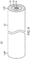
FIG. 6 is a perspective view of a layered member of the present invention prior to drawing. - With reference to
FIGS. 1 ,2A and 2B , a drawn thermocouple coaxialwire pair member 10 of the present invention includes a single elongatedtensile body 12 with a generally circular cross-section. Themember 10 has an electrically-conductive core 14 defining a longitudinal axis of thebody 12. Thecore 14 includes a metallic material as a first wire of the wire pair. Themember 10 also has an electrically-conductivecoaxial layer 16 that includes a different or dissimilar metallic material as a second wire of the wire pair. Advantageously, extending along the length of thebody 12, between themetallic core 14 and themetallic layer 16, is an electrically insulatinglayer 18 that surrounds thecore 14 and separates and isolates it from thelayer 16. Thecore 14 and themetallic layer 16 may be of any suitable metals, including, for example, constantan and copper, or vice versa. The insulatinglayer 18 may be of any suitable material, including, for example, ceramic. An electrically insulatingouter sheath 26 may be provided over the entirety of the member. With a coaxial construction providing a generally circular cross-section, as shown inFIG. 2B , themember 10 has an improved profile in terms of utility, convenience and aesthetics. The metallic materials for the first and second wires of themember 10 may be copper and constantan, or vice versa. Alternately, they may be any other dissimilar metals that form a thermocouple. The insulatinglayer 18 may be constructed of any suitable material, including, for example, a polymer and/or ceramic. The insulatingsheath 26 may be constructed of any suitable material, including, for example, a polymer. The preferred method of applyingsheath 26 would be a film casting method used to insulate magnet wires, as shown in the art. - As shown in
FIG. 2A ,distal end 12D of themember 10 has asolder cap 20D of a filler metal forming a distal junction of a circuit C between the core 14 and thelayer 16. As a "hot" or "measuring junction," thedistal solder cap 20D is adapted for measuring temperature of tissue. Proximally, the two conductive layers are attached to wires of corresponding material, as shown inFIG. 2C . This can be accomplished by grinding thesheath 26, and thelayers proximal end 12P of the member 10 (as shown in broken lines) to expose thecore 14. Distally to this grinding, thesheath 26 can be removed mechanically or thermally to expose thelayer 16. Once exposed, thelayers distal solder cap 20D can be any solder preferred by the industry, but are usually primarily comprised of tin. - With reference to
FIG. 3A , a catheterdistal tip 32 includes adistal tip electrode 30 having adistal end 30D adapted for contact with tissue for diagnostic and/or therapeutic procedures by means of alead wire 40 whose distal end is anchored and potted in ablind hole 42. Thetip electrode 30 also has aproximal end 30P whose face is configured with ablind hole 34 for receiving thedistal end 12D andsolder cap 20D of the thermocouplewire pair member 10 of the present invention. Theblind hole 34 has predetermined and known depth X at an end or "bottom" 36 at which thedistal solder cap 20D is placed and potted linearly without any bends or folds in the portion of themember 10 in thehole 34. Thus, the precise location of thedistal solder cap 20D (the "hot junction") is known relative to the distal tip electrode when temperature is measured by themember 10 at thedistal tip electrode 30. As understood in the art, themember 10 extends through acatheter 60 from thedistal tip 32, through a catheter shaft 62 (with a deflection section 64) into acontrol handle 66 where it is connected to anelectrical connector 68 at the proximal end of the handle, as shown inFIG. 4 . It is further understood that one ormore members 10 may be used with any distal electrode assembly, whether the assembly has a 2-D configuration of a 3-D configuration, for example, circular-, lasso-, basket- or spine-type catheter. - The present invention includes a method of manufacturing a thermocouple
wire pair member 10. The thermocouple wire pair first may be shapened by drawing processes owned and practiced by Fort Wayne Metals Research Products Corporation (Fort Wayne, Indiana), a manufacturer of precision wire-based materials for medical and industrial applications. With reference toFIG. 6 , a layered (predrawn) member 10' includes the elongatedsolid core 14 of a first metallic material which is surrounded circumferentially by a layer of insulating material (e.g., ceramic) forming the insulatinglayer 18. Thecore 14 and thelayer 18 are surrounded circumferentially by a layer of a second metallic material dissimilar to the first metallic material of the core, forming theouter layer 16. The member 10' may be assembled with the core 14 configured as a solid rod that is inserted into a first, inner hollow tube as thelayer 18, and then together into a second, outer hollow tube as thelayer 16. With reference toFIG. 5 , the member 10', as described above, having an original outer diameter D1 is passed through a die 50 adapted to receive an end of the member 10' to draw it into desired shape and size, including a resulting drawn smaller outer diameter D2. Adie holder 52 is provided to hold thedie 50. The drawing process may be "cold" or "hot" drawn as desired or appropriate. The member 10' may be pushed and/or pulled through thedie 50, as known in the art. As the member 10' is drawn through the die, any or all of thecore 14 and thelayers member 10. Where the insulatinglayer 18 is ceramic, the ceramic is crushed or otherwise broken into smaller particles. After repeated drawing, the ceramic may be crushed intopowder form 44. Typically, the drawing process would be for multiple thousands of feet at a time. As shown inFIG. 6 , the formed member comprising thecore 14 and thelayers - After the member 10' has been drawn into the
member 10 with anelongated body 12 with a desirable diameter, thedistal end 12D is prepared for a solder cap by being trimmed to expose thecore 14 and thelayer 16, and dipped in solder to formdistal solder cap 20D, as shown iFIG. 2A . Preferably, thedistal solder cap 20D does not extend radially past theouter sheath 26. In other words, thesolder cap 20D has a diameter no greater than the diameter of the drawnmember 10 with theouter sheath 26. As shown inFIG. 2C , theproximal end 12P is also prepared for soldering by removal of all layers, including thecoating 26, and thelayers coating 26, to expose thelayer 16, and soldering wires W1 and W2 of corresponding materials to the exposedcore 14 and the exposedlayer 16, respectively. - The preceding description has been presented with reference to presently preferred embodiments of the invention. Workers skilled in the art and technology to which this invention pertains will appreciate that alterations and changes in the described structure may be practiced without meaningfully departing from the principal, spirit and scope of this invention. As understood by one of ordinary skill in the art, the drawings are not necessarily to scale. Also, different features of one or more embodiments may be combined as needed or appropriate. Moreover, the catheters described herein may be configured to apply various energy forms, including microwave, laser, RF and/or cryogens. Accordingly, the foregoing description should not be read as pertaining only to the precise structures described and illustrated in the accompanying drawings, but rather should be read consistent with and as support to the following claims which are to have their fullest and fair scope.
- The following is a numbered list of aspects of the disclosure:
- 1. A temperature sensing tensile member for use with a medical device, comprising:
- an elongated body having a proximal end and a distal end, the body comprising:
a core of a first metallic material, the core defining a longitudinal axis, a first coaxial layer of ceramic material circumferentially surrounding the core, and a second coaxial layer of a second metallic material circumferentially surrounding the first layer, the second metallic material being different from the first metallic material, the first layer electrically insulating the core and second layer from each other along the length of the body, and - a solder cap on the distal end, the solder cap electrically connecting the core and the second layer at the distal end.
- an elongated body having a proximal end and a distal end, the body comprising:
- 2. The temperature sensing tensile member of aspect 1, wherein the ceramic material is crushable.
- 3. A medical device comprising:
- an elongated catheter body;
- a distal electrode member;
- a temperature sensor having a tensile body, the tensile body extending through the catheter body and having at least a distal end received in the distal electrode member, the temperature sensor comprising:
- a core of a first metallic material defining a longitudinal axis;
- a coaxial insulating material circumferentially surrounding the core along its length; and
- a coaxial layer of a second metallic material circumferentially surrounding the insulating material along its length; and
- a solder cap on the distal end of the tensile body, the solder cap electrically connecting the core and the layer.
- 4. The temperature sensing tensile member of aspect 1 or the medical device of aspect 3, wherein the core includes constantan and the second layer includes copper, or the core includes copper and the second layer includes constantan.
- 5. The medical device of
aspect 4, wherein the coaxial insulating material includes ceramic particulates. - 6. The temperature sensing tensile member of aspect 1 or the medical device of
aspect 4, further comprising an outer protective sheath. - 7. The temperature sensing tensile member or the medical device of aspect 6, wherein the outer protective sheath is electrically nonconductive.
- 8. The temperature sensing tensile member of claim 1 or the medical device of
claim 4, wherein the body has been drawn through a die. - 9. A method of manufacturing a coaxial thermocouple wire pair member adapted for use with an electrophysiologic catheter, comprising:
- providing a core of a first metallic material defining a longitudinal axis;
- coaxially surrounding the core with an insulating ceramic material;
- coaxially surrounding the insulating material with a second metallic material different from the first metallic material;
- drawing the member through a die; and
- applying solder on a distal end of the member to electrically connect the core and the metallic layer at the distal end.
- 10. The method of aspect 9, further comprising:
Forming an electrically non-conductive layer on the outside of the drawn thermocouple wire pair member by a film cast method. - 11. The method of aspect 9, further comprising:
trimming the distal end to expose the core and the layer after drawing the member through a die and before applying solder on the distal end. - 12. The method of aspect 9, wherein drawing the member through a die crushes the insulating ceramic material.
- 13. The method of aspect 9, wherein drawing the member through a die generally crushes the insulating ceramic material into particulates.
- 14. The method of aspect 9, wherein drawing the member through a die generally crushes the insulating ceramic material into powder.
- 15. The method of aspect 9, where one of the first metallic material and the second metallic material is copper and the other of the first metallic material and the second metallic material is constantan.
Claims (11)
- A medical device comprising:an elongated catheter body;a distal electrode member;a temperature sensor having a tensile body, the tensile body extending through the catheter body and having at least a distal end received in the distal electrode member, the temperature sensor comprising:a core of a first metallic material defining a longitudinal axis;a first coaxial layer of insulating material circumferentially surrounding the core along its length; anda second coaxial layer of a second metallic material circumferentially surrounding the insulating material along its length; anda solder cap on the distal end of the tensile body, the solder cap electrically connecting the core and the second layer.
- The medical device of claim 1, wherein the distal electrode member further comprises a proximal end having a first blind hole, and wherein the solder cap is placed and potted linearly at an end of the first blind hole without any bends or folds in the portion of the temperature sensor in the first blind hole.
- The medical device of claim 2, wherein the end of the first blind hole has a predetermined and known depth.
- The medical device of any preceding claim, wherein the distal electrode member further comprises a second blind hole, wherein a distal end of a lead wire is anchored and potted in the second blind hole.
- The medical device of any preceding claim, wherein the tensile body is an elongated body having a proximal end and a distal end and comprises:the core; the first coaxial layer, wherein the insulting material is a ceramic material;and the second coaxial layer, wherein the second metallic material is different from the first metallic material and the first layer electrically insulates the core and second layer from each other along the length of the body.
- The medical device of claim 5, wherein the ceramic material is crushable.
- The medical device of any preceding claim, wherein the core includes constantan and the second layer includes copper, or the core includes copper and the second layer includes constantan.
- The medical device of claim 7, wherein the coaxial insulating material includes ceramic particulates.
- The medical device of claim 7, further comprising an outer protective sheath.
- The medical device of claim 9, wherein the outer protective sheath is electrically nonconductive.
- The medical device of claim 7, wherein the body has been drawn through a die.
Applications Claiming Priority (2)
| Application Number | Priority Date | Filing Date | Title |
|---|---|---|---|
| US14/714,904 US10285754B2 (en) | 2015-05-18 | 2015-05-18 | Catheter with coaxial thermocouple |
| EP16169868.3A EP3095403B1 (en) | 2015-05-18 | 2016-05-17 | Catheter with coaxial thermocouple |
Related Parent Applications (1)
| Application Number | Title | Priority Date | Filing Date |
|---|---|---|---|
| EP16169868.3A Division EP3095403B1 (en) | 2015-05-18 | 2016-05-17 | Catheter with coaxial thermocouple |
Publications (1)
| Publication Number | Publication Date |
|---|---|
| EP3777744A1 true EP3777744A1 (en) | 2021-02-17 |
Family
ID=56008527
Family Applications (2)
| Application Number | Title | Priority Date | Filing Date |
|---|---|---|---|
| EP16169868.3A Active EP3095403B1 (en) | 2015-05-18 | 2016-05-17 | Catheter with coaxial thermocouple |
| EP20192188.9A Withdrawn EP3777744A1 (en) | 2015-05-18 | 2016-05-17 | Catheter with coaxial thermocouple |
Family Applications Before (1)
| Application Number | Title | Priority Date | Filing Date |
|---|---|---|---|
| EP16169868.3A Active EP3095403B1 (en) | 2015-05-18 | 2016-05-17 | Catheter with coaxial thermocouple |
Country Status (7)
| Country | Link |
|---|---|
| US (2) | US10285754B2 (en) |
| EP (2) | EP3095403B1 (en) |
| JP (2) | JP6862101B2 (en) |
| CN (2) | CN113288403B (en) |
| AU (1) | AU2016202415A1 (en) |
| CA (1) | CA2928229A1 (en) |
| IL (2) | IL245170B (en) |
Families Citing this family (8)
| Publication number | Priority date | Publication date | Assignee | Title |
|---|---|---|---|---|
| US10285754B2 (en) | 2015-05-18 | 2019-05-14 | Biosense Webster (Israel) Ltd. | Catheter with coaxial thermocouple |
| US20190117298A1 (en) * | 2017-10-25 | 2019-04-25 | Biosense Webster (Israel) Ltd. | Catheter with improved temperature response |
| CN119791824A (en) * | 2019-07-30 | 2025-04-11 | 波士顿科学国际有限公司 | Electrosurgery Tips |
| JP7212006B2 (en) * | 2020-06-12 | 2023-01-24 | 日本碍子株式会社 | Thermocouple guide and ceramic heater |
| CN112494134B (en) * | 2020-11-27 | 2022-04-22 | 威脉清通医疗科技(无锡)有限公司 | Thermocouple, heat ablation catheter with same and heat ablation device |
| CN113091936B (en) * | 2021-04-06 | 2022-03-01 | 华中科技大学 | Coaxial film thermocouple suitable for measuring transient temperature on surface of 42CrMo steel piston |
| CN113352269A (en) * | 2021-06-15 | 2021-09-07 | 徐州工业职业技术学院 | Accurate positioning and assembling device for thermocouple for computer communication |
| US12588432B2 (en) | 2022-02-25 | 2026-03-24 | Bard Access Systems, Inc. | Methods for transferring graphene to substrates and related lithographic stacks and laminates |
Citations (7)
| Publication number | Priority date | Publication date | Assignee | Title |
|---|---|---|---|---|
| DE2454620B1 (en) * | 1974-11-18 | 1976-02-12 | Kraftwerk Union Ag | Coaxial half-finished thermoelement of any length - which is flexible, of extremely low inertia and insertable in any medium |
| US5111002A (en) * | 1991-01-28 | 1992-05-05 | Omega Engineering, Inc. | Method of fabricating thermocouple cable and the cable resulting therefrom |
| JPH05299703A (en) * | 1992-04-17 | 1993-11-12 | Fuji Electric Co Ltd | Coaxial type thermocouple |
| WO1995001656A1 (en) * | 1993-07-01 | 1995-01-12 | Hoskins Manufacturing Company | Coaxial thermoelements and thermocouples made from the coaxial thermoelements |
| EP0900547A1 (en) * | 1997-09-05 | 1999-03-10 | Cordis Webster, Inc. | Steerable catheter for detecting and revascularizing ischemic myocardial tissue |
| EP0928600A2 (en) * | 1997-12-01 | 1999-07-14 | Cordis Webster, Inc. | Steerable catheter with electromagnetic sensor |
| US20020165534A1 (en) * | 2001-05-02 | 2002-11-07 | Hayzelden Robert C. | Steerable catheter with torque transfer system |
Family Cites Families (32)
| Publication number | Priority date | Publication date | Assignee | Title |
|---|---|---|---|---|
| US3343589A (en) | 1964-06-25 | 1967-09-26 | San Fernando Lab | Gaseous deposition method of making a thermocouple probe |
| US4512827A (en) | 1981-09-21 | 1985-04-23 | Associated Electrical Industries Limited | Method of manufacturing mineral insulated electric cable and like elements |
| US4408088A (en) | 1982-02-10 | 1983-10-04 | Berkley And Company, Inc. | Aramid reinforced thermocouple cable |
| US4460802A (en) | 1982-12-15 | 1984-07-17 | Westinghouse Electric Corporation | Radially activated thermocouple assembly |
| JPS6115380A (en) | 1984-06-30 | 1986-01-23 | Toshiba Corp | thermocouple |
| US4732619A (en) * | 1987-01-08 | 1988-03-22 | Nanmac Corporation | Self renewing thermocouple |
| JPH01105411A (en) * | 1987-06-12 | 1989-04-21 | Kobe Steel Ltd | Manufacture of composite oxide ceramic wire material coated by metallic material |
| WO1993008756A1 (en) * | 1991-11-08 | 1993-05-13 | Ep Technologies, Inc. | Radiofrequency ablation with phase sensitive power detection |
| ATE241938T1 (en) * | 1991-11-08 | 2003-06-15 | Boston Scient Ltd | ABLATION ELECTRODE WITH INSULATED TEMPERATURE MEASUREMENT ELEMENT |
| GB9210377D0 (en) * | 1992-05-14 | 1992-07-01 | Lucas Ind Plc | Thermocouples |
| US5464485A (en) * | 1993-07-01 | 1995-11-07 | Hoskins Manufacturing Co. | Coaxial thermoelements and thermocouples made from coaxial thermoelements |
| WO1995005212A2 (en) * | 1993-08-11 | 1995-02-23 | Electro-Catheter Corporation | Improved ablation electrode |
| EP0768841B1 (en) * | 1994-06-27 | 2003-12-03 | Boston Scientific Limited | System for controlling tissue ablation using temperature sensors |
| US5853409A (en) * | 1994-06-27 | 1998-12-29 | E.P. Technologies, Inc. | Systems and apparatus for sensing temperature in body tissue |
| US5606974A (en) * | 1995-05-02 | 1997-03-04 | Heart Rhythm Technologies, Inc. | Catheter having ultrasonic device |
| US5843076A (en) * | 1995-06-12 | 1998-12-01 | Cordis Webster, Inc. | Catheter with an electromagnetic guidance sensor |
| GB9606630D0 (en) * | 1996-03-29 | 1996-06-05 | Bicc Plc | Manufacture of mineral insulated thermocouple probes |
| US6176857B1 (en) * | 1997-10-22 | 2001-01-23 | Oratec Interventions, Inc. | Method and apparatus for applying thermal energy to tissue asymmetrically |
| US6120476A (en) * | 1997-12-01 | 2000-09-19 | Cordis Webster, Inc. | Irrigated tip catheter |
| US6049737A (en) * | 1998-05-05 | 2000-04-11 | Cardiac Pacemakers, Inc. | Catheter having common lead for electrode and sensor |
| CA2403366A1 (en) | 1999-08-16 | 2001-02-22 | Temperature Management Systems (Proprietary) Limited | Metallurgical thermocouple |
| US6475214B1 (en) * | 2000-05-01 | 2002-11-05 | Biosense Webster, Inc. | Catheter with enhanced ablation electrode |
| DE10342709A1 (en) * | 2003-09-11 | 2005-04-21 | Biotronik Gmbh & Co Kg | catheter |
| US8215955B2 (en) | 2006-10-18 | 2012-07-10 | Bnl Biotech Co., Ltd. | Endodontic instrument for root canal filling and heating tip adapted to the same |
| US20090211173A1 (en) * | 2008-02-27 | 2009-08-27 | General Electric Company | Composite wind turbine tower |
| CN201223445Y (en) * | 2008-06-23 | 2009-04-22 | 北京有色金属研究总院 | Radio frequency ablation catheter |
| JP2010060445A (en) * | 2008-09-04 | 2010-03-18 | Okazaki Mfg Co Ltd | Inert gas encapsulated sheathed thermocouple and method for manufacturing the same |
| KR101844086B1 (en) * | 2010-01-05 | 2018-03-30 | 큐로 메디컬 인크. | Medical heating device and method with self-limiting electrical heating element |
| CN201950084U (en) * | 2010-09-30 | 2011-08-31 | H.福克桑德林有限公司 | Device for squeezing metal |
| US9091603B2 (en) * | 2012-09-26 | 2015-07-28 | Biosense Webster (Israel) Ltd. | Temperature simulator for thermocouple-based RF ablation system |
| US10281337B2 (en) * | 2013-09-20 | 2019-05-07 | Furuya Metal Co., Ltd. | Thermocouple and manufacturing method for same |
| US10285754B2 (en) | 2015-05-18 | 2019-05-14 | Biosense Webster (Israel) Ltd. | Catheter with coaxial thermocouple |
-
2015
- 2015-05-18 US US14/714,904 patent/US10285754B2/en active Active
-
2016
- 2016-04-15 AU AU2016202415A patent/AU2016202415A1/en not_active Abandoned
- 2016-04-17 IL IL245170A patent/IL245170B/en active IP Right Grant
- 2016-04-26 CA CA2928229A patent/CA2928229A1/en not_active Abandoned
- 2016-05-17 EP EP16169868.3A patent/EP3095403B1/en active Active
- 2016-05-17 EP EP20192188.9A patent/EP3777744A1/en not_active Withdrawn
- 2016-05-17 JP JP2016098608A patent/JP6862101B2/en active Active
- 2016-05-18 CN CN202110405660.8A patent/CN113288403B/en active Active
- 2016-05-18 CN CN201610329891.4A patent/CN106166059B/en active Active
-
2019
- 2019-04-03 US US16/373,702 patent/US10918437B2/en active Active
- 2019-11-27 IL IL270980A patent/IL270980B/en active IP Right Grant
-
2021
- 2021-03-31 JP JP2021060067A patent/JP7073555B2/en active Active
Patent Citations (7)
| Publication number | Priority date | Publication date | Assignee | Title |
|---|---|---|---|---|
| DE2454620B1 (en) * | 1974-11-18 | 1976-02-12 | Kraftwerk Union Ag | Coaxial half-finished thermoelement of any length - which is flexible, of extremely low inertia and insertable in any medium |
| US5111002A (en) * | 1991-01-28 | 1992-05-05 | Omega Engineering, Inc. | Method of fabricating thermocouple cable and the cable resulting therefrom |
| JPH05299703A (en) * | 1992-04-17 | 1993-11-12 | Fuji Electric Co Ltd | Coaxial type thermocouple |
| WO1995001656A1 (en) * | 1993-07-01 | 1995-01-12 | Hoskins Manufacturing Company | Coaxial thermoelements and thermocouples made from the coaxial thermoelements |
| EP0900547A1 (en) * | 1997-09-05 | 1999-03-10 | Cordis Webster, Inc. | Steerable catheter for detecting and revascularizing ischemic myocardial tissue |
| EP0928600A2 (en) * | 1997-12-01 | 1999-07-14 | Cordis Webster, Inc. | Steerable catheter with electromagnetic sensor |
| US20020165534A1 (en) * | 2001-05-02 | 2002-11-07 | Hayzelden Robert C. | Steerable catheter with torque transfer system |
Also Published As
| Publication number | Publication date |
|---|---|
| JP7073555B2 (en) | 2022-05-23 |
| JP2021100662A (en) | 2021-07-08 |
| EP3095403A2 (en) | 2016-11-23 |
| US10918437B2 (en) | 2021-02-16 |
| EP3095403B1 (en) | 2020-09-16 |
| IL245170A0 (en) | 2016-08-31 |
| IL245170B (en) | 2019-12-31 |
| CA2928229A1 (en) | 2016-11-18 |
| CN113288403A (en) | 2021-08-24 |
| CN106166059A (en) | 2016-11-30 |
| US10285754B2 (en) | 2019-05-14 |
| CN113288403B (en) | 2024-04-16 |
| AU2016202415A1 (en) | 2016-12-08 |
| US20190223952A1 (en) | 2019-07-25 |
| JP6862101B2 (en) | 2021-04-21 |
| EP3095403A3 (en) | 2017-01-04 |
| JP2016214861A (en) | 2016-12-22 |
| CN106166059B (en) | 2021-07-06 |
| US20160338768A1 (en) | 2016-11-24 |
| IL270980A (en) | 2020-01-30 |
| IL270980B (en) | 2021-06-30 |
Similar Documents
| Publication | Publication Date | Title |
|---|---|---|
| US10918437B2 (en) | Catheter with coaxial thermocouple | |
| JP7516630B2 (en) | Method for manufacturing a catheter having improved temperature response | |
| EP3836861B1 (en) | Catheter ablation device with impedance monitoring | |
| EP3510956B1 (en) | Thermally isolated thermocouple | |
| EP3536275B1 (en) | Positioning cartridge for electrode | |
| US10801899B2 (en) | Position-biasing thermocouple |
Legal Events
| Date | Code | Title | Description |
|---|---|---|---|
| PUAI | Public reference made under article 153(3) epc to a published international application that has entered the european phase |
Free format text: ORIGINAL CODE: 0009012 |
|
| STAA | Information on the status of an ep patent application or granted ep patent |
Free format text: STATUS: THE APPLICATION HAS BEEN PUBLISHED |
|
| AC | Divisional application: reference to earlier application |
Ref document number: 3095403 Country of ref document: EP Kind code of ref document: P |
|
| AK | Designated contracting states |
Kind code of ref document: A1 Designated state(s): AL AT BE BG CH CY CZ DE DK EE ES FI FR GB GR HR HU IE IS IT LI LT LU LV MC MK MT NL NO PL PT RO RS SE SI SK SM TR |
|
| STAA | Information on the status of an ep patent application or granted ep patent |
Free format text: STATUS: REQUEST FOR EXAMINATION WAS MADE |
|
| 17P | Request for examination filed |
Effective date: 20210511 |
|
| RBV | Designated contracting states (corrected) |
Designated state(s): AL AT BE BG CH CY CZ DE DK EE ES FI FR GB GR HR HU IE IS IT LI LT LU LV MC MK MT NL NO PL PT RO RS SE SI SK SM TR |
|
| RAP3 | Party data changed (applicant data changed or rights of an application transferred) |
Owner name: BIOSENSE WEBSTER (ISRAEL) LTD. |
|
| STAA | Information on the status of an ep patent application or granted ep patent |
Free format text: STATUS: EXAMINATION IS IN PROGRESS |
|
| 17Q | First examination report despatched |
Effective date: 20240223 |
|
| STAA | Information on the status of an ep patent application or granted ep patent |
Free format text: STATUS: THE APPLICATION HAS BEEN WITHDRAWN |
|
| 18W | Application withdrawn |
Effective date: 20240611 |