EP3777508A1 - String trimmer with blower - Google Patents
String trimmer with blower Download PDFInfo
- Publication number
- EP3777508A1 EP3777508A1 EP20188109.1A EP20188109A EP3777508A1 EP 3777508 A1 EP3777508 A1 EP 3777508A1 EP 20188109 A EP20188109 A EP 20188109A EP 3777508 A1 EP3777508 A1 EP 3777508A1
- Authority
- EP
- European Patent Office
- Prior art keywords
- fan
- ring
- cutting device
- housing
- gear
- Prior art date
- Legal status (The legal status is an assumption and is not a legal conclusion. Google has not performed a legal analysis and makes no representation as to the accuracy of the status listed.)
- Granted
Links
Images








Classifications
-
- A—HUMAN NECESSITIES
- A01—AGRICULTURE; FORESTRY; ANIMAL HUSBANDRY; HUNTING; TRAPPING; FISHING
- A01G—HORTICULTURE; CULTIVATION OF VEGETABLES, FLOWERS, RICE, FRUIT, VINES, HOPS OR SEAWEED; FORESTRY; WATERING
- A01G20/00—Cultivation of turf, lawn or the like; Apparatus or methods therefor
- A01G20/40—Apparatus for cleaning the lawn or grass surface
- A01G20/43—Apparatus for cleaning the lawn or grass surface for sweeping, collecting or disintegrating lawn debris
- A01G20/47—Vacuum or blower devices
-
- A—HUMAN NECESSITIES
- A01—AGRICULTURE; FORESTRY; ANIMAL HUSBANDRY; HUNTING; TRAPPING; FISHING
- A01D—HARVESTING; MOWING
- A01D34/00—Mowers; Mowing apparatus of harvesters
- A01D34/01—Mowers; Mowing apparatus of harvesters characterised by features relating to the type of cutting apparatus
- A01D34/412—Mowers; Mowing apparatus of harvesters characterised by features relating to the type of cutting apparatus having rotating cutters
- A01D34/416—Flexible line cutters
-
- A—HUMAN NECESSITIES
- A01—AGRICULTURE; FORESTRY; ANIMAL HUSBANDRY; HUNTING; TRAPPING; FISHING
- A01D—HARVESTING; MOWING
- A01D69/00—Driving mechanisms or parts thereof for harvesters or mowers
- A01D69/06—Gearings
-
- F—MECHANICAL ENGINEERING; LIGHTING; HEATING; WEAPONS; BLASTING
- F04—POSITIVE - DISPLACEMENT MACHINES FOR LIQUIDS; PUMPS FOR LIQUIDS OR ELASTIC FLUIDS
- F04D—NON-POSITIVE-DISPLACEMENT PUMPS
- F04D17/00—Radial-flow pumps, e.g. centrifugal pumps; Helico-centrifugal pumps
- F04D17/08—Centrifugal pumps
-
- F—MECHANICAL ENGINEERING; LIGHTING; HEATING; WEAPONS; BLASTING
- F16—ENGINEERING ELEMENTS AND UNITS; GENERAL MEASURES FOR PRODUCING AND MAINTAINING EFFECTIVE FUNCTIONING OF MACHINES OR INSTALLATIONS; THERMAL INSULATION IN GENERAL
- F16H—GEARING
- F16H1/00—Toothed gearings for conveying rotary motion
- F16H1/02—Toothed gearings for conveying rotary motion without gears having orbital motion
- F16H1/04—Toothed gearings for conveying rotary motion without gears having orbital motion involving only two intermeshing members
- F16H1/06—Toothed gearings for conveying rotary motion without gears having orbital motion involving only two intermeshing members with parallel axes
-
- F—MECHANICAL ENGINEERING; LIGHTING; HEATING; WEAPONS; BLASTING
- F16—ENGINEERING ELEMENTS AND UNITS; GENERAL MEASURES FOR PRODUCING AND MAINTAINING EFFECTIVE FUNCTIONING OF MACHINES OR INSTALLATIONS; THERMAL INSULATION IN GENERAL
- F16H—GEARING
- F16H57/00—General details of gearing
- F16H57/0018—Shaft assemblies for gearings
- F16H57/0031—Shaft assemblies for gearings with gearing elements rotatable supported on the shaft
Definitions
- the present invention is a string trimmer in combination with a blower.
- String trimmers with filament cutting lines are well known in the art. These string trimmers have a cutting head that is rotated at a high speed, with the filament line extending out from the cutting head to cut through grass and other light vegetation. This offers users a portable and easy to use cutting tool, but the cut grass often leave a messy appearance.
- the present invention is directed to a string trimmer for cutting grass that includes a blower for blowing the cut debris.
- the string trimmer has a cutting head with a spool housing for holding a spool with cutting line.
- a motor is connected to the spool housing to rotate the cutting line at high speed.
- the cutting head also includes a fan for generating an airflow for the blowing function.
- a transmission is provided in the cutting head for selectively engaging the spool housing.
- the motor rotates in a first direction, and through the use of a one-way pinion gear, the spool housing is operatively driven and rotated to cut grass.
- the motor is rotated in a second direction, opposite to the first.
- the fan which is directly connected to the motor, rotates to generate the airflow.
- the one-way pinion gear does not transfer the rotation of the motor to the spool housing and so no cutting function is actuated.
- the one-way gear has an inner ring with a series of ramps around is perimeter and an outer ring surrounding the inner ring.
- a series of rollers are located in between the inner ring and outer ring, and in the first mode of operation the rollers move up the ramps to lock the inner ring and outer ring together for joint rotation, and in the second mode of operation, the rollers move down the ramp to allow the inner ring to rotate freely with respect to the outer ring.
- the one-way gear comprises a ring with a series of rollers partially exposed around its inner perimeter.
- the rollers sit in a cavity and depending on the rotation of the motor, either freely rotate or engage an edge of the cavity to lock the rollers with the ring.
- the cutting head includes a fan housing having a volute that extends around the fan housing to direct air out of the fan housing.
- a locking lever is provided that engages with the teeth of the drive gear. Since the drive gear is connected to the spool housing, the lever prevents the spool housing from rotating when the tool is in the blower mode. In yet another embodiment of the invention, the lever is replaced with a second one-way gear to prevent the spool housing from rotating.
- the fan is a radial fan having a top plate, a bottom plate and a series of blades between the top plate and the bottom plate.
- a vegetation cutting device comprising: a motor having a drive shaft; a fan fixedly connected to the drive shaft; a pinion gear fixedly connected to the drive shaft; a drive gear connected to the pinion gear; a spool housing fixedly connected to the drive gear; and wherein the spool housing is selectively rotatable with the motor drive shaft.
- the motor In a first mode of operation the motor may rotate in a first direction where the fan and the spool housing are rotated, and in a second mode of operation the motor may rotate in a second direction opposite to the first and the fan is rotated and the spool housing is not rotated.
- the pinion gear may be a one-way gear that drives the drive gear when rotated in the first direction and does not drive the drive gear when rotated in a second direction.
- the pinion gear may have an inner ring with a series of ramps around is perimeter, an outer ring surrounding the inner ring, and rollers located in between the inner ring and outer ring, wherein in the first mode of operation the rollers move up the ramps to lock the inner ring and outer ring together for joint rotation, and in the second mode of operation, the rollers move down the ramp to allow the inner ring to rotate freely with respect to the outer ring.
- the pinion gear may include a ring having a series of rollers around an inside perimeter of the ring, the rollers positioned within a cavity in the ring, and in a first mode of operation the rollers lock the ring to the drive shaft, and in a second mode of operation the rollers allow the pinion gear to rotate freely with respect to the drive shaft.
- the vegetation cutting device may further comprise a cutting head, the cutting head having a fan housing enclosing the fan, the fan housing having a volute that extends around the fan housing to direct air out of the cutting head.
- the cutting head may further include a transmission housing for enclosing the pinion gear and the drive gear, where the transmission housing is below the fan housing.
- the fan may be a radial fan having a top plate, a bottom plate and a series of blades between the top plate and the bottom plate.
- the vegetation cutting device may further comprising a locking mechanism connected to the spool housing, the locking mechanism allowing the spool housing to rotate in a first direction and locking rotation of the spool housing in a second direction.
- a vegetation cutting device comprising: a cutting head having a fan housing enclosing a fan and a spool housing adapted to hold a spool with filament line for cutting vegetation; wherein one of the fan or the spool housing is selectively engageable with a drive shaft of a motor, and the other of the fan or spool housing is fixedly connected to the drive shaft; wherein the vegetation cutting device has a first mode of operation where the motor rotates in a first direction and both the fan and spool housing are rotated, and a second mode of operation where only one of the fan or spool housing is rotated.
- the vegetation cutting device may further comprise a one-way gear that selectively rotates one of the fan or spool housing depending on the direction of rotation of the motor.
- the one-way gear may have an inner ring with a series of ramps around is perimeter, an outer ring surrounding the inner ring, and rollers located in between the inner ring and outer ring, wherein in the first mode of operation the rollers move up the ramps to lock the inner ring and outer ring together for joint rotation, and in the second mode of operation, the rollers move down the ramp to allow the inner ring to rotate freely with respect to the outer ring.
- the one-way gear may include a ring having a series of roller located around its inside perimeter, the roller located in a cavity in the ring and movable between a locked position to lock the rollers with respect to the ring, and an unlocked position where the rollers are allowed to freely rotate with respect to the ring.
- the cutting head may include a volute that directs air out of the cutting head.
- a vegetation cutting device comprising: a cutting head housing a fan, a pinion gear connected to the fan and a drive gear connected to the pinion gear; a motor having a drive shaft drivingly connected to the fan; a spool housing adapted to hold a spool with filament line connected to the drive gear; wherein the pinion gear is a one-way gear that selectively drives the drive gear; wherein in a first mode of operation the motor rotates in a first direction and both the fan and spool housing are rotated, and in a second mode of operation only the fan is rotated.
- the pinion gear may selectively rotate the spool housing depending on the direction of rotation of the motor.
- the pinion gear may have an inner ring with a series of ramps around is perimeter, an outer ring surrounding the inner ring, and rollers located in between the inner ring and outer ring, wherein in the first mode of operation the rollers move up the ramps to lock the inner ring and outer ring together for joint rotation, and in the second mode of operation, the rollers move down the ramp to allow the inner ring to rotate freely with respect to the outer ring.
- the pinion gear may include a ring having a series of roller located around its inside perimeter, the roller located in a cavity in the ring and movable between a locked position to lock the rollers with respect to the ring, and an unlocked position where the rollers are allowed to freely rotate with respect to the ring.
- the cutting head may include a volute that directs air out of the cutting head.
- Fig. 1 shows a string trimmer 10 according to an embodiment of the present invention.
- the string trimmer 10 includes a main housing 12 on a first end of a support member 14 and a cutting head 16 on an opposing end of the support member 14.
- the main housing 12 encloses a motor (not shown) and includes a primary handle 18 with a trigger 15 for providing power to the motor and a secondary support handle 20.
- Fig. 1A shows a slide switch 13 on the main housing 12 for reversing the direction of the motor.
- the motor can be powered by a rechargeable battery or by an AC power cord.
- the cutting head 16 has an upper portion defined by a fan housing 22 and a lower portion made up of a transmission housing 24. Below the transmission housing 24 is a spool housing 26 for holding a spool (not shown) with filament line. A volute or outlet nozzle 21 partially encircles the fan housing 22, and a guard 17 lies below the volute.
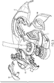
- the cutting head 16 is formed from multiple pieces, as shown in the exploded view of Fig. 3 , with two clamshell portions 100, 102 forming the main part of the cutting head. Two cover portions 104 and 106 are secured to each other around the clamshell portions 100 and 102.
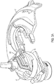
- the volute 21 is formed by the clamshell portions 100 and 102 and by cover portions 104 and 106. As best shown in Fig. 3A , the clamshells 100 and 102 are not identical, with clamshell 100 being larger than clamshell 102, thus forming an airtube 200 that leads directly into an air pathway formed by cover portion 106. These together form the volute 21.
- the fan housing 22 is shown enclosing a fan 28.
- a top portion of the fan housing 22 has an opening 23 that allows the support member 14 to pass through.
- the support member 14 is a hollow tube and holds a flexible drive shaft 30 that extends from the motor to the fan 28.
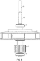
- Fig. 5 shows the drive shaft 30 secured to a fan coupling member 29.
- the fan coupling member 29 is fixedly connected to the fan 28 and includes bearings 31 and 32 above and below the fan, respectively.
- a locking one-way pinion gear 34 is secured to the fan coupling member 29 below the fan 28.
- the fan housing 22 includes vents 25 (also seen in Fig. 2 ) that allow outside air to enter the fan housing 22. The air then pass through a center opening in the fan 28 and is expelled out laterally through the side of the fan. The airpath is shown by arrows in Fig. 4 . The air then passes into the volute 21 and expelled out of the cutting head.
- the pinion gear 34 which is fixedly secured to the fan coupling member 29, engages a drive gear 36.
- the drive gear 36 is fixed to the spool housing 26 via shaft 40.
- the shaft 40 is held in place by bearings 42 and 44.
- the pinion gear 34 and drive gear 36 are positioned inside the transmission housing 24.
- the pinion gear 34 is a locking one-way gear that allows it to selectively rotate the drive gear 36.
- Fig. 6 shows the locking pinion gear 34 having an outer ring 50 and an inner ring 52
- Fig. 6A shows the internal structure between the two rings.
- the inner ring 52 has a series of ramps 54 having an inclined surface 56 that ends in a vertical wall 58.
- the ramps 54 are evenly spaced around the circumference of the inner ring 52.
- Rollers 60 are placed on the inclined surface 56, with the outer ring 50 holding the rollers 60 in place. A small clearance is provided between the roller 60 and the outer ring 50 when the roller is positioned at the bottom of the inclined surface 56.
- the rollers 60 move up the inclined surface 56 and contact the outer ring 50.
- the rollers 60 lock the two rings together and force the outer ring 50 to rotate with the inner ring 52.
- the rollers 60 move to the bottom of the inclined surface 56 and allowing the outer ring 50 to rotate freely with respect to the inner ring 52.
- the string trimmer can selectively actuate the cutting feature on the string trimmer. For instance, in a first mode of operation, when a cutting operation is desired, the motor is rotated in the counter-clockwise direction which drives the pinon gear 34 in a counter-clockwise direction, thereby locking its inner and outer rings together. The pinion gear 34 then rotates the drive gear 36 and the spool housing 26.
- the motor rotates in the clockwise direction, which drives the inner ring 52 of the pinion gear 34 in a clockwise direction.
- the ring ring 52 is allowed to rotate freely relative to the outer ring 50, and thus no rotation is imparted to the drive gear 36 and the spool housing 26 does not rotate.
- the fan 28 is rotating because it is fixedly connected, via the fan coupling member 29, to the drive shaft 30. Because the fan 28 is needed when the blowing feature is desired, it may be designed to be optimized only for the second mode of operation.
- the fan blades 74 can be designed so that when the fan is in the blow mode, it generates increased airflow compared to when it's operating in the trimming mode, where the blowing feature is not needed. Although the fan still produces some airflow in the trimming mode, it is incidental to the operation of the cutting and does not affect the tool's performance.
- Figs. 7 and 7A show an alternate embodiment of the pinion gear.
- the gear 300 is formed from a single ring 302 with rollers 304 embedded within the ring and slightly protruding from its interior surface.
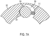
- Fig. 7A is a sectional view showing the ring 302 having a cavity 306 where the roller 304 sits.
- the fan coupling member 29 extends through the center opening of the ring and engages the roller 304.
- the cavity 306 includes a V-shaped cutout 308 and a spring 310.
- the drive shaft rotates in a counter-clockwise direction, which pushes the roller 304 against the cutout 308.
- the edges of the cutout create friction points that "grab" the rollers and lock the ring 302 to the drive shaft 30.
- this actuates rotation of the drive gear 36 and spool housing 26.
- the motor is reversed and the drive shaft 30 rotates in the clockwise direction.
- the roller 304 is pushed against the spring 310, away from contact with the cavity walls 306, allowing it to freely rotate, with little to no rotation being imparted to the spool housing 26.
- the transmission housing 24 includes a locking lever 400 positioned adjacent the drive gear 36.
- the lever 400 is affixed to one of the clamshells 100 or 102 through an aperture 402 at the base of the lever.
- the lever is generally Z-shaped, with an extension portion 403 and a head portion 404 that contacts the teeth 35 of the drive gear 36.
- the lever 400 allows the gear 36 to rotate in the clockwise direction, but helps to quickly stop rotation of the spool housing 26 when no power is delivered to the motor. This reduces possible injury to the user from the rotating line.
- the shape of the lever 400 prevents the gear 36 from rotating in the counter-clockwise direction and so the spool housing does not rotate in this mode.
- Fig. 9 shows an alternate embodiment for locking mechanism shown in Fig. 8 .
- the locking lever 400 is replaced with a one-way gear 410, which is similar to the one-way gear 300 described earlier and shown in Figs. 7 and 7A .
- the outer ring 302 of the gear 410 is fixedly secured in an opening 412 in the housings 100 or 102.
- the same shaft 40 that holds the drive gear 36, bearings 42 and 44 and spool housing 26 is inserted through the central opening of the gear 410, and so depending on its direction of rotation, it can freely rotate or is locked.
- the motor rotates in a counter-clockwise direction and the shaft 40 would rotate in a clockwise direction.
- the motor and shaft rotate in the reverse. Therefore, the operation and internal structure of the one-way gear 410 is identical to the pinion gear 34, except that its locking mechanism is in reverse.
Landscapes
- Engineering & Computer Science (AREA)
- General Engineering & Computer Science (AREA)
- Life Sciences & Earth Sciences (AREA)
- Environmental Sciences (AREA)
- Mechanical Engineering (AREA)
- Harvester Elements (AREA)
Abstract
Description
- The present invention is a string trimmer in combination with a blower.
- String trimmers with filament cutting lines are well known in the art. These string trimmers have a cutting head that is rotated at a high speed, with the filament line extending out from the cutting head to cut through grass and other light vegetation. This offers users a portable and easy to use cutting tool, but the cut grass often leave a messy appearance.
- Users who wish to maintain a clean yard must then use a broom or a blower to move the debris off sidewalks and other areas. Needing a second tool requires an additional expense and the hassle of having to retrieve the tool when needed. Therefore, it would be desirable to have a string trimmer with a blower feature incorporated into the tool.
- Accordingly, the present invention is directed to a string trimmer for cutting grass that includes a blower for blowing the cut debris. The string trimmer has a cutting head with a spool housing for holding a spool with cutting line. A motor is connected to the spool housing to rotate the cutting line at high speed. The cutting head also includes a fan for generating an airflow for the blowing function.
- A transmission is provided in the cutting head for selectively engaging the spool housing. In a first mode of operation where the cutting feature is desired, the motor rotates in a first direction, and through the use of a one-way pinion gear, the spool housing is operatively driven and rotated to cut grass. In a second mode of operation, where only the blowing feature is desired, the motor is rotated in a second direction, opposite to the first. The fan, which is directly connected to the motor, rotates to generate the airflow. However, the one-way pinion gear does not transfer the rotation of the motor to the spool housing and so no cutting function is actuated.
- In an embodiment of the invention, the one-way gear has an inner ring with a series of ramps around is perimeter and an outer ring surrounding the inner ring. A series of rollers are located in between the inner ring and outer ring, and in the first mode of operation the rollers move up the ramps to lock the inner ring and outer ring together for joint rotation, and in the second mode of operation, the rollers move down the ramp to allow the inner ring to rotate freely with respect to the outer ring.
- In another embodiment of the invention, the one-way gear comprises a ring with a series of rollers partially exposed around its inner perimeter. The rollers sit in a cavity and depending on the rotation of the motor, either freely rotate or engage an edge of the cavity to lock the rollers with the ring.
- In a further embodiment, the cutting head includes a fan housing having a volute that extends around the fan housing to direct air out of the fan housing.
- In another embodiment of the invention, a locking lever is provided that engages with the teeth of the drive gear. Since the drive gear is connected to the spool housing, the lever prevents the spool housing from rotating when the tool is in the blower mode. In yet another embodiment of the invention, the lever is replaced with a second one-way gear to prevent the spool housing from rotating.
- In yet a further embodiment, the fan is a radial fan having a top plate, a bottom plate and a series of blades between the top plate and the bottom plate.
- In one aspect there is provided a vegetation cutting device comprising: a motor having a drive shaft; a fan fixedly connected to the drive shaft; a pinion gear fixedly connected to the drive shaft; a drive gear connected to the pinion gear; a spool housing fixedly connected to the drive gear; and wherein the spool housing is selectively rotatable with the motor drive shaft.
- In a first mode of operation the motor may rotate in a first direction where the fan and the spool housing are rotated, and in a second mode of operation the motor may rotate in a second direction opposite to the first and the fan is rotated and the spool housing is not rotated.
- The pinion gear may be a one-way gear that drives the drive gear when rotated in the first direction and does not drive the drive gear when rotated in a second direction.
- The pinion gear may have an inner ring with a series of ramps around is perimeter, an outer ring surrounding the inner ring, and rollers located in between the inner ring and outer ring, wherein in the first mode of operation the rollers move up the ramps to lock the inner ring and outer ring together for joint rotation, and in the second mode of operation, the rollers move down the ramp to allow the inner ring to rotate freely with respect to the outer ring.
- The pinion gear may include a ring having a series of rollers around an inside perimeter of the ring, the rollers positioned within a cavity in the ring, and in a first mode of operation the rollers lock the ring to the drive shaft, and in a second mode of operation the rollers allow the pinion gear to rotate freely with respect to the drive shaft.
- The vegetation cutting device may further comprise a cutting head, the cutting head having a fan housing enclosing the fan, the fan housing having a volute that extends around the fan housing to direct air out of the cutting head. The cutting head may further include a transmission housing for enclosing the pinion gear and the drive gear, where the transmission housing is below the fan housing.
- The fan may be a radial fan having a top plate, a bottom plate and a series of blades between the top plate and the bottom plate.
- The vegetation cutting device may further comprising a locking mechanism connected to the spool housing, the locking mechanism allowing the spool housing to rotate in a first direction and locking rotation of the spool housing in a second direction.
- In another aspect there is provided a vegetation cutting device comprising: a cutting head having a fan housing enclosing a fan and a spool housing adapted to hold a spool with filament line for cutting vegetation; wherein one of the fan or the spool housing is selectively engageable with a drive shaft of a motor, and the other of the fan or spool housing is fixedly connected to the drive shaft; wherein the vegetation cutting device has a first mode of operation where the motor rotates in a first direction and both the fan and spool housing are rotated, and a second mode of operation where only one of the fan or spool housing is rotated.
- The vegetation cutting device may further comprise a one-way gear that selectively rotates one of the fan or spool housing depending on the direction of rotation of the motor.
- The one-way gear may have an inner ring with a series of ramps around is perimeter, an outer ring surrounding the inner ring, and rollers located in between the inner ring and outer ring, wherein in the first mode of operation the rollers move up the ramps to lock the inner ring and outer ring together for joint rotation, and in the second mode of operation, the rollers move down the ramp to allow the inner ring to rotate freely with respect to the outer ring. The one-way gear may include a ring having a series of roller located around its inside perimeter, the roller located in a cavity in the ring and movable between a locked position to lock the rollers with respect to the ring, and an unlocked position where the rollers are allowed to freely rotate with respect to the ring.
- The cutting head may include a volute that directs air out of the cutting head.
- In another aspect there is provided a vegetation cutting device comprising: a cutting head housing a fan, a pinion gear connected to the fan and a drive gear connected to the pinion gear; a motor having a drive shaft drivingly connected to the fan; a spool housing adapted to hold a spool with filament line connected to the drive gear; wherein the pinion gear is a one-way gear that selectively drives the drive gear; wherein in a first mode of operation the motor rotates in a first direction and both the fan and spool housing are rotated, and in a second mode of operation only the fan is rotated.
- The pinion gear may selectively rotate the spool housing depending on the direction of rotation of the motor.
- The pinion gear may have an inner ring with a series of ramps around is perimeter, an outer ring surrounding the inner ring, and rollers located in between the inner ring and outer ring, wherein in the first mode of operation the rollers move up the ramps to lock the inner ring and outer ring together for joint rotation, and in the second mode of operation, the rollers move down the ramp to allow the inner ring to rotate freely with respect to the outer ring.
- The pinion gear may include a ring having a series of roller located around its inside perimeter, the roller located in a cavity in the ring and movable between a locked position to lock the rollers with respect to the ring, and an unlocked position where the rollers are allowed to freely rotate with respect to the ring.
- The cutting head may include a volute that directs air out of the cutting head.
- Further features and advantages of the present invention will be better understood by reference to the following description, which is given by way of example and in association with the accompanying drawings, in which:
-
Fig. 1 is a perspective view of a string trimmer according to an embodiment of the invention; -
Fig. 1A is a view of the main housing of the string trimmer; -
Fig. 2 is view of the cutting head of the string trimmer; -
Fig. 3 is an exploded view of the cutting head ofFig. 2 ; -
Fig. 3A is a partially assembled view of the cutting head; -
Fig. 4 is a sectional view of the cutting head; -
Fig. 4A is a side view ofFig. 4 ; -
Fig. 5 is a side view of the fan and fan coupling member; -
Fig. 6 shows a first embodiment of a locking one-way pinion gear; -
Fig. 6A is an internal view of the pinion gearFig. 6 ; -
Fig. 7 shows a second embodiment of a locking one-way pinion gear; -
Fig. 7A is an internal view of the pinion gear ofFig. 7 ; -
Fig. 8 shows a locking lever for the drive gear; and -
Fig. 9 shows a second embodiment of a locking mechanism for the drive gear. -
Fig. 1 shows astring trimmer 10 according to an embodiment of the present invention. Thestring trimmer 10 includes amain housing 12 on a first end of asupport member 14 and a cuttinghead 16 on an opposing end of thesupport member 14. Themain housing 12 encloses a motor (not shown) and includes aprimary handle 18 with atrigger 15 for providing power to the motor and asecondary support handle 20.Fig. 1A shows aslide switch 13 on themain housing 12 for reversing the direction of the motor. The motor can be powered by a rechargeable battery or by an AC power cord. - Referring now to
Fig. 2 , the cuttinghead 16 has an upper portion defined by afan housing 22 and a lower portion made up of atransmission housing 24. Below thetransmission housing 24 is aspool housing 26 for holding a spool (not shown) with filament line. A volute oroutlet nozzle 21 partially encircles thefan housing 22, and aguard 17 lies below the volute. - The cutting
head 16 is formed from multiple pieces, as shown in the exploded view ofFig. 3 , with twoclamshell portions cover portions clamshell portions volute 21 is formed by theclamshell portions cover portions Fig. 3A , theclamshells clamshell 100 being larger thanclamshell 102, thus forming anairtube 200 that leads directly into an air pathway formed bycover portion 106. These together form thevolute 21. - Referring to
Figs. 4 and4A , thefan housing 22 is shown enclosing afan 28. A top portion of thefan housing 22 has anopening 23 that allows thesupport member 14 to pass through. Thesupport member 14 is a hollow tube and holds aflexible drive shaft 30 that extends from the motor to thefan 28.Fig. 5 shows thedrive shaft 30 secured to afan coupling member 29. Thefan coupling member 29 is fixedly connected to thefan 28 and includesbearings way pinion gear 34 is secured to thefan coupling member 29 below thefan 28. - Referring back to
Fig. 4 , thefan housing 22 includes vents 25 (also seen inFig. 2 ) that allow outside air to enter thefan housing 22. The air then pass through a center opening in thefan 28 and is expelled out laterally through the side of the fan. The airpath is shown by arrows inFig. 4 . The air then passes into thevolute 21 and expelled out of the cutting head. - Referring again to
Figs. 4 and4A , thepinion gear 34, which is fixedly secured to thefan coupling member 29, engages adrive gear 36. Thedrive gear 36 is fixed to thespool housing 26 viashaft 40. Theshaft 40 is held in place bybearings pinion gear 34 and drivegear 36 are positioned inside thetransmission housing 24. - Now referring to
Figs. 6 and6A , thepinion gear 34 is a locking one-way gear that allows it to selectively rotate thedrive gear 36.Fig. 6 shows thelocking pinion gear 34 having anouter ring 50 and aninner ring 52, andFig. 6A shows the internal structure between the two rings. Theinner ring 52 has a series oframps 54 having aninclined surface 56 that ends in avertical wall 58. Theramps 54 are evenly spaced around the circumference of theinner ring 52.Rollers 60 are placed on theinclined surface 56, with theouter ring 50 holding therollers 60 in place. A small clearance is provided between theroller 60 and theouter ring 50 when the roller is positioned at the bottom of theinclined surface 56. - When the
inner ring 52 ofthepinion gear 34 is rotated (through rotation of the drive shaft 30) in a counter-clockwise direction, therollers 60 move up theinclined surface 56 and contact theouter ring 50. Therollers 60 lock the two rings together and force theouter ring 50 to rotate with theinner ring 52. When theinner ring 52 rotates in a clockwise direction, therollers 60 move to the bottom of theinclined surface 56 and allowing theouter ring 50 to rotate freely with respect to theinner ring 52. - So, depending on the rotation of the motor, the string trimmer can selectively actuate the cutting feature on the string trimmer. For instance, in a first mode of operation, when a cutting operation is desired, the motor is rotated in the counter-clockwise direction which drives the
pinon gear 34 in a counter-clockwise direction, thereby locking its inner and outer rings together. Thepinion gear 34 then rotates thedrive gear 36 and thespool housing 26. - In a second mode of operation, where only the blowing operation is desired, the motor rotates in the clockwise direction, which drives the
inner ring 52 of thepinion gear 34 in a clockwise direction. Here, thering ring 52 is allowed to rotate freely relative to theouter ring 50, and thus no rotation is imparted to thedrive gear 36 and thespool housing 26 does not rotate. - It's noteworthy that in both modes of operation, the
fan 28 is rotating because it is fixedly connected, via thefan coupling member 29, to thedrive shaft 30. Because thefan 28 is needed when the blowing feature is desired, it may be designed to be optimized only for the second mode of operation. For example, thefan blades 74 can be designed so that when the fan is in the blow mode, it generates increased airflow compared to when it's operating in the trimming mode, where the blowing feature is not needed. Although the fan still produces some airflow in the trimming mode, it is incidental to the operation of the cutting and does not affect the tool's performance. -
Figs. 7 and7A show an alternate embodiment of the pinion gear. Here thegear 300 is formed from asingle ring 302 withrollers 304 embedded within the ring and slightly protruding from its interior surface.Fig. 7A is a sectional view showing thering 302 having acavity 306 where theroller 304 sits. Thefan coupling member 29 extends through the center opening of the ring and engages theroller 304. Thecavity 306 includes a V-shapedcutout 308 and aspring 310. - In the first mode of operation when trimming is desired, the drive shaft rotates in a counter-clockwise direction, which pushes the
roller 304 against thecutout 308. The edges of the cutout create friction points that "grab" the rollers and lock thering 302 to thedrive shaft 30. Like in the previous embodiment, this actuates rotation of thedrive gear 36 andspool housing 26. In the second mode of operation when only blowing is desired, the motor is reversed and thedrive shaft 30 rotates in the clockwise direction. Theroller 304 is pushed against thespring 310, away from contact with thecavity walls 306, allowing it to freely rotate, with little to no rotation being imparted to thespool housing 26. - It should be noted that although two types of one-way gears have been disclosed in the present specification, any one-way gear mechanism may fall within the scope of the invention.
- Now referring to
Fig. 8 , a further embodiment of the invention is shown. Here thetransmission housing 24 includes a lockinglever 400 positioned adjacent thedrive gear 36. Thelever 400 is affixed to one of theclamshells aperture 402 at the base of the lever. The lever is generally Z-shaped, with anextension portion 403 and ahead portion 404 that contacts theteeth 35 of thedrive gear 36. When operating in the trimming mode, thelever 400 allows thegear 36 to rotate in the clockwise direction, but helps to quickly stop rotation of thespool housing 26 when no power is delivered to the motor. This reduces possible injury to the user from the rotating line. When operating in the blow mode, the shape of thelever 400 prevents thegear 36 from rotating in the counter-clockwise direction and so the spool housing does not rotate in this mode. -
Fig. 9 shows an alternate embodiment for locking mechanism shown inFig. 8 . Here, the lockinglever 400 is replaced with a one-way gear 410, which is similar to the one-way gear 300 described earlier and shown inFigs. 7 and7A . Theouter ring 302 of thegear 410 is fixedly secured in anopening 412 in thehousings same shaft 40 that holds thedrive gear 36,bearings spool housing 26 is inserted through the central opening of thegear 410, and so depending on its direction of rotation, it can freely rotate or is locked. In this instance, when the tool is operating in the trimming mode, the motor rotates in a counter-clockwise direction and theshaft 40 would rotate in a clockwise direction. When the tool is operating in the blowing mode, the motor and shaft rotate in the reverse. Therefore, the operation and internal structure of the one-way gear 410 is identical to thepinion gear 34, except that its locking mechanism is in reverse. - The foregoing description of the embodiments has been provided for purposes of illustration and description. It is not intended to be exhaustive or to limit the disclosure. Individual elements or features of a particular embodiment are generally not limited to that particular embodiment, but, where applicable, are interchangeable and can be used in a selected embodiment, even if not specifically shown or described. The same may also be varied in many ways. Such variations are not to be regarded as a departure from the disclosure, and all such modifications are intended to be included within the scope of the disclosure
Claims (15)
- A vegetation cutting device comprising:a cutting head having a fan housing enclosing a fan and a spool housing adapted to hold a spool with a line for cutting vegetation;wherein one of the fan or the spool housing is selectively engageable with a drive shaft of a motor, and the other of the fan or spool housing is fixedly connected to the drive shaft;wherein the vegetation cutting device has a first mode of operation where the motor rotates in a first direction and both the fan and spool housing are rotated, and a second mode of operation where only one of the fan or spool housing is rotated.
- The vegetation cutting device of claim 1, further comprising:a pinion gear fixedly connected to the drive shaft; anda drive gear connected to the pinion gear, wherein:the fan is fixedly connected to the drive shaft;the spool housing is fixedly connected to the drive gear; andthe spool housing is selectively rotatable with the drive shaft.
- The vegetation cutting device of claim 2, wherein in the second mode of operation the motor rotates in a second direction opposite to the first and the fan is rotated and the spool housing is not rotated.
- The vegetation cutting device of claim 3, wherein the pinion gear is a one-way gear that drives the drive gear when rotated in the first direction and does not drive the drive gear when rotated in a second direction.
- The vegetation cutting device of claim 4, wherein the pinion gear has an inner ring with a series of ramps around is perimeter, an outer ring surrounding the inner ring, and rollers located in between the inner ring and outer ring, wherein in the first mode of operation the rollers move up the ramps to lock the inner ring and outer ring together for joint rotation, and in the second mode of operation, the rollers move down the ramp to allow the inner ring to rotate freely with respect to the outer ring.
- The vegetation cutting device of claim 4, wherein the pinion gear includes a ring having a series of rollers around an inside perimeter of the ring, the rollers positioned within a cavity in the ring, and in a first mode of operation the rollers lock the ring to the drive shaft, and in a second mode of operation the rollers allow the pinion gear to rotate freely with respect to the drive shaft.
- The vegetation cutting device of any preceding claim, wherein the fan housing comprises a volute that extends around the fan housing to direct air out of the cutting head.
- The vegetation cutting device of claim 7, wherein the cutting head further includes a transmission housing for enclosing the pinion gear and the drive gear, where the transmission housing is below the fan housing.
- The vegetation cutting device of claim 7 or 8, wherein the fan is a radial fan having a top plate, a bottom plate and a series of blades between the top plate and the bottom plate.
- The vegetation cutting device of any of claims 7 to 9, further comprising a locking mechanism connected to the spool housing, the locking mechanism allowing the spool housing to rotate in a first direction and locking rotation of the spool housing in a second direction.
- The vegetation cutting device of claim 1, further comprising a one-way gear that selectively rotates one of the fan or spool housing depending on the direction of rotation of the motor.
- The vegetation cutting device of claim 1, further comprising a pinion gear connected to the fan and a drive gear connected to the pinion gear, wherein:the drive shaft is drivingly connected to the fan;the spool housing is connected to the drive gear;the pinion gear is a one-way gear that selectively drives the drive gear; andin the second mode of operation only the fan is rotated.
- The vegetation cutting device of claim 12, wherein the pinion gear selectively rotates the spool housing depending on the direction of rotation of the motor.
- The vegetation cutting device of claim 13, wherein the pinion gear has an inner ring with a series of ramps around is perimeter, an outer ring surrounding the inner ring, and rollers located in between the inner ring and outer ring, wherein in the first mode of operation the rollers move up the ramps to lock the inner ring and outer ring together for joint rotation, and in the second mode of operation, the rollers move down the ramp to allow the inner ring to rotate freely with respect to the outer ring.
- The vegetation cutting device of claim 13, wherein the pinion gear includes a ring having a series of roller located around its inside perimeter, the roller located in a cavity in the ring and movable between a locked position to lock the rollers with respect to the ring, and an unlocked position where the rollers are allowed to freely rotate with respect to the ring.
Applications Claiming Priority (1)
| Application Number | Priority Date | Filing Date | Title |
|---|---|---|---|
| US16/528,729 US11432479B2 (en) | 2019-08-01 | 2019-08-01 | String trimmer with blower |
Publications (2)
| Publication Number | Publication Date |
|---|---|
| EP3777508A1 true EP3777508A1 (en) | 2021-02-17 |
| EP3777508B1 EP3777508B1 (en) | 2023-08-30 |
Family
ID=71842577
Family Applications (1)
| Application Number | Title | Priority Date | Filing Date |
|---|---|---|---|
| EP20188109.1A Active EP3777508B1 (en) | 2019-08-01 | 2020-07-28 | String trimmer with blower |
Country Status (2)
| Country | Link |
|---|---|
| US (1) | US11432479B2 (en) |
| EP (1) | EP3777508B1 (en) |
Families Citing this family (6)
| Publication number | Priority date | Publication date | Assignee | Title |
|---|---|---|---|---|
| WO2019061095A1 (en) * | 2017-09-27 | 2019-04-04 | Changzhou Globe Co., Ltd. | Impact protecting member for a cutting tool |
| CN113016327A (en) * | 2021-03-12 | 2021-06-25 | 格力博(江苏)股份有限公司 | Grass trimmer |
| CN218587683U (en) * | 2022-09-30 | 2023-03-10 | 格力博(江苏)股份有限公司 | Drive assembly and garden instrument |
| USD1001160S1 (en) * | 2023-01-02 | 2023-10-10 | Yagui Li | Lawn mower |
| USD996933S1 (en) * | 2023-01-09 | 2023-08-29 | Yongkang Xinsen Industry and Trade Co., Ltd. | Lawn mower |
| CN118985264A (en) * | 2024-09-05 | 2024-11-22 | 宁波汉浦工具有限公司 | Grass mowing machine |
Citations (4)
| Publication number | Priority date | Publication date | Assignee | Title |
|---|---|---|---|---|
| JPH04121107A (en) * | 1990-09-11 | 1992-04-22 | Honda Motor Co Ltd | Rotating type lawn mower |
| US20090038283A1 (en) * | 2007-08-08 | 2009-02-12 | Hurley Edward P | Combination blower, edger and trimmer and method for tending vegetation |
| DE202016006000U1 (en) * | 2015-12-25 | 2016-11-07 | Makita Corporation | Electrically powered implement |
| US20180271012A1 (en) * | 2016-01-22 | 2018-09-27 | Nanjing Chervon Industry Co., Ltd. | Grass trimmer, operating method thereof and control method thereof |
Family Cites Families (15)
| Publication number | Priority date | Publication date | Assignee | Title |
|---|---|---|---|---|
| AU742951B2 (en) | 1998-02-20 | 2002-01-17 | Black & Decker Incorporated | Combination string and blade trimmer with auxiliary blower function |
| US6349475B1 (en) | 1999-11-12 | 2002-02-26 | Mark A. Buck | Debris blowing weed trimmer |
| US7047592B2 (en) | 2003-02-12 | 2006-05-23 | Mtd Products, Inc. | Combination blower assembly and string trimmer |
| US7100287B2 (en) | 2003-06-10 | 2006-09-05 | Mccoid Trevor Albert | Trimmer lawn mowing device |
| US20060123635A1 (en) | 2004-12-09 | 2006-06-15 | Heow, Inc. | Combination blower, trimmer and edger for tending vegetation |
| US20070209346A1 (en) | 2006-03-13 | 2007-09-13 | Bovo Peter J | Combined weed whacker, blower and vacuum apparatus |
| US7739800B2 (en) | 2006-10-24 | 2010-06-22 | Hurley Edward P | Combination blower, trimmer and edger for tending vegetation |
| DE602007006499D1 (en) * | 2007-10-05 | 2010-06-24 | Black & Decker Inc | Plant cutting device with blowing function |
| US20100088902A1 (en) | 2008-10-10 | 2010-04-15 | Edward Patrick Hurley | Handheld lawn tool |
| US20110131815A1 (en) | 2009-12-08 | 2011-06-09 | Hurley Edward P | Combination blower and trimmer assembly |
| US8914981B1 (en) | 2013-01-23 | 2014-12-23 | Bruce A. Paez | Weed cutter with vacuum |
| US9472992B2 (en) | 2013-07-11 | 2016-10-18 | The Toro Company | Electric motor support structure and power equipment unit incorporating same |
| CN105557179B (en) | 2014-10-23 | 2018-03-20 | 南京德朔实业有限公司 | Grass-mowing machine |
| US9750180B2 (en) * | 2014-10-23 | 2017-09-05 | Crary Industries, Inc. | Powered landscaping system |
| US11426854B2 (en) * | 2017-12-11 | 2022-08-30 | Emak S.P.A. | Work tool with motor and fan |
-
2019
- 2019-08-01 US US16/528,729 patent/US11432479B2/en active Active
-
2020
- 2020-07-28 EP EP20188109.1A patent/EP3777508B1/en active Active
Patent Citations (4)
| Publication number | Priority date | Publication date | Assignee | Title |
|---|---|---|---|---|
| JPH04121107A (en) * | 1990-09-11 | 1992-04-22 | Honda Motor Co Ltd | Rotating type lawn mower |
| US20090038283A1 (en) * | 2007-08-08 | 2009-02-12 | Hurley Edward P | Combination blower, edger and trimmer and method for tending vegetation |
| DE202016006000U1 (en) * | 2015-12-25 | 2016-11-07 | Makita Corporation | Electrically powered implement |
| US20180271012A1 (en) * | 2016-01-22 | 2018-09-27 | Nanjing Chervon Industry Co., Ltd. | Grass trimmer, operating method thereof and control method thereof |
Also Published As
| Publication number | Publication date |
|---|---|
| US20210029898A1 (en) | 2021-02-04 |
| US11432479B2 (en) | 2022-09-06 |
| EP3777508B1 (en) | 2023-08-30 |
Similar Documents
| Publication | Publication Date | Title |
|---|---|---|
| US11432479B2 (en) | String trimmer with blower | |
| US5933966A (en) | Shaft telescoping and rotational adjustment mechanism for a lawn and garden tool | |
| US11785884B2 (en) | Trimmer head and grass trimmer | |
| EP2044829B1 (en) | Vegetation trimmer having a blowing function | |
| US10894310B2 (en) | Power tool having interchangeable tool heads with an independent accessory switch | |
| US4183138A (en) | Apparatus for cutting vegetation | |
| ES2235424T3 (en) | ELECTRICAL TOOL, ESPECIALLY ANGULAR GRINDER. | |
| US5642566A (en) | Electric powered cable cutter | |
| US6732752B2 (en) | Fan assembly for an umbrella | |
| US4161820A (en) | Apparatus for cutting vegetation | |
| US11412656B2 (en) | Trimmer head with improved line release feature | |
| ES2235423T3 (en) | ELECTRICAL TOOL, ESPECIALLY ANGULAR GRINDER. | |
| US4899446A (en) | Hand-held machine with power disengaging means | |
| US20060053632A1 (en) | Hair clipper with pivot head | |
| AU2013200717B2 (en) | Vacuum and/or blower device | |
| US4168572A (en) | Apparatus for cutting vegetation | |
| US20110005083A1 (en) | Pipe cutter | |
| CN102656657B (en) | Electric hand tool with activation indication device | |
| EP2204082A1 (en) | Electric mower having two-motion activation system | |
| JPH1119820A (en) | Power cutting machine with dust suction device | |
| US20060248731A1 (en) | Bush cutter | |
| US20160227705A1 (en) | String trimmer head | |
| GB2383554A (en) | Hair clipper with pivoting handle | |
| WO2020001637A1 (en) | Hand propelled electric power tool | |
| US4236311A (en) | Vegetation cutting apparatus |
Legal Events
| Date | Code | Title | Description |
|---|---|---|---|
| PUAI | Public reference made under article 153(3) epc to a published international application that has entered the european phase |
Free format text: ORIGINAL CODE: 0009012 |
|
| STAA | Information on the status of an ep patent application or granted ep patent |
Free format text: STATUS: THE APPLICATION HAS BEEN PUBLISHED |
|
| AK | Designated contracting states |
Kind code of ref document: A1 Designated state(s): AL AT BE BG CH CY CZ DE DK EE ES FI FR GB GR HR HU IE IS IT LI LT LU LV MC MK MT NL NO PL PT RO RS SE SI SK SM TR |
|
| AX | Request for extension of the european patent |
Extension state: BA ME |
|
| STAA | Information on the status of an ep patent application or granted ep patent |
Free format text: STATUS: REQUEST FOR EXAMINATION WAS MADE |
|
| 17P | Request for examination filed |
Effective date: 20210813 |
|
| RBV | Designated contracting states (corrected) |
Designated state(s): AL AT BE BG CH CY CZ DE DK EE ES FI FR GB GR HR HU IE IS IT LI LT LU LV MC MK MT NL NO PL PT RO RS SE SI SK SM TR |
|
| GRAP | Despatch of communication of intention to grant a patent |
Free format text: ORIGINAL CODE: EPIDOSNIGR1 |
|
| STAA | Information on the status of an ep patent application or granted ep patent |
Free format text: STATUS: GRANT OF PATENT IS INTENDED |
|
| RIC1 | Information provided on ipc code assigned before grant |
Ipc: A01D 69/06 20060101ALI20230504BHEP Ipc: A01D 34/416 20060101AFI20230504BHEP |
|
| INTG | Intention to grant announced |
Effective date: 20230519 |
|
| GRAS | Grant fee paid |
Free format text: ORIGINAL CODE: EPIDOSNIGR3 |
|
| GRAA | (expected) grant |
Free format text: ORIGINAL CODE: 0009210 |
|
| STAA | Information on the status of an ep patent application or granted ep patent |
Free format text: STATUS: THE PATENT HAS BEEN GRANTED |
|
| AK | Designated contracting states |
Kind code of ref document: B1 Designated state(s): AL AT BE BG CH CY CZ DE DK EE ES FI FR GB GR HR HU IE IS IT LI LT LU LV MC MK MT NL NO PL PT RO RS SE SI SK SM TR |
|
| REG | Reference to a national code |
Ref country code: GB Ref legal event code: FG4D |
|
| REG | Reference to a national code |
Ref country code: CH Ref legal event code: EP |
|
| REG | Reference to a national code |
Ref country code: DE Ref legal event code: R096 Ref document number: 602020016565 Country of ref document: DE |
|
| REG | Reference to a national code |
Ref country code: IE Ref legal event code: FG4D |
|
| REG | Reference to a national code |
Ref country code: LT Ref legal event code: MG9D |
|
| REG | Reference to a national code |
Ref country code: NL Ref legal event code: MP Effective date: 20230830 |
|
| REG | Reference to a national code |
Ref country code: AT Ref legal event code: MK05 Ref document number: 1604129 Country of ref document: AT Kind code of ref document: T Effective date: 20230830 |
|
| PG25 | Lapsed in a contracting state [announced via postgrant information from national office to epo] |
Ref country code: GR Free format text: LAPSE BECAUSE OF FAILURE TO SUBMIT A TRANSLATION OF THE DESCRIPTION OR TO PAY THE FEE WITHIN THE PRESCRIBED TIME-LIMIT Effective date: 20231201 |
|
| PG25 | Lapsed in a contracting state [announced via postgrant information from national office to epo] |
Ref country code: IS Free format text: LAPSE BECAUSE OF FAILURE TO SUBMIT A TRANSLATION OF THE DESCRIPTION OR TO PAY THE FEE WITHIN THE PRESCRIBED TIME-LIMIT Effective date: 20231230 |
|
| PG25 | Lapsed in a contracting state [announced via postgrant information from national office to epo] |
Ref country code: SE Free format text: LAPSE BECAUSE OF FAILURE TO SUBMIT A TRANSLATION OF THE DESCRIPTION OR TO PAY THE FEE WITHIN THE PRESCRIBED TIME-LIMIT Effective date: 20230830 Ref country code: RS Free format text: LAPSE BECAUSE OF FAILURE TO SUBMIT A TRANSLATION OF THE DESCRIPTION OR TO PAY THE FEE WITHIN THE PRESCRIBED TIME-LIMIT Effective date: 20230830 Ref country code: NO Free format text: LAPSE BECAUSE OF FAILURE TO SUBMIT A TRANSLATION OF THE DESCRIPTION OR TO PAY THE FEE WITHIN THE PRESCRIBED TIME-LIMIT Effective date: 20231130 Ref country code: LV Free format text: LAPSE BECAUSE OF FAILURE TO SUBMIT A TRANSLATION OF THE DESCRIPTION OR TO PAY THE FEE WITHIN THE PRESCRIBED TIME-LIMIT Effective date: 20230830 Ref country code: LT Free format text: LAPSE BECAUSE OF FAILURE TO SUBMIT A TRANSLATION OF THE DESCRIPTION OR TO PAY THE FEE WITHIN THE PRESCRIBED TIME-LIMIT Effective date: 20230830 Ref country code: IS Free format text: LAPSE BECAUSE OF FAILURE TO SUBMIT A TRANSLATION OF THE DESCRIPTION OR TO PAY THE FEE WITHIN THE PRESCRIBED TIME-LIMIT Effective date: 20231230 Ref country code: HR Free format text: LAPSE BECAUSE OF FAILURE TO SUBMIT A TRANSLATION OF THE DESCRIPTION OR TO PAY THE FEE WITHIN THE PRESCRIBED TIME-LIMIT Effective date: 20230830 Ref country code: GR Free format text: LAPSE BECAUSE OF FAILURE TO SUBMIT A TRANSLATION OF THE DESCRIPTION OR TO PAY THE FEE WITHIN THE PRESCRIBED TIME-LIMIT Effective date: 20231201 Ref country code: FI Free format text: LAPSE BECAUSE OF FAILURE TO SUBMIT A TRANSLATION OF THE DESCRIPTION OR TO PAY THE FEE WITHIN THE PRESCRIBED TIME-LIMIT Effective date: 20230830 Ref country code: AT Free format text: LAPSE BECAUSE OF FAILURE TO SUBMIT A TRANSLATION OF THE DESCRIPTION OR TO PAY THE FEE WITHIN THE PRESCRIBED TIME-LIMIT Effective date: 20230830 |
|
| PG25 | Lapsed in a contracting state [announced via postgrant information from national office to epo] |
Ref country code: PL Free format text: LAPSE BECAUSE OF FAILURE TO SUBMIT A TRANSLATION OF THE DESCRIPTION OR TO PAY THE FEE WITHIN THE PRESCRIBED TIME-LIMIT Effective date: 20230830 Ref country code: NL Free format text: LAPSE BECAUSE OF FAILURE TO SUBMIT A TRANSLATION OF THE DESCRIPTION OR TO PAY THE FEE WITHIN THE PRESCRIBED TIME-LIMIT Effective date: 20230830 |
|
| PG25 | Lapsed in a contracting state [announced via postgrant information from national office to epo] |
Ref country code: ES Free format text: LAPSE BECAUSE OF FAILURE TO SUBMIT A TRANSLATION OF THE DESCRIPTION OR TO PAY THE FEE WITHIN THE PRESCRIBED TIME-LIMIT Effective date: 20230830 |
|
| PG25 | Lapsed in a contracting state [announced via postgrant information from national office to epo] |
Ref country code: SM Free format text: LAPSE BECAUSE OF FAILURE TO SUBMIT A TRANSLATION OF THE DESCRIPTION OR TO PAY THE FEE WITHIN THE PRESCRIBED TIME-LIMIT Effective date: 20230830 Ref country code: RO Free format text: LAPSE BECAUSE OF FAILURE TO SUBMIT A TRANSLATION OF THE DESCRIPTION OR TO PAY THE FEE WITHIN THE PRESCRIBED TIME-LIMIT Effective date: 20230830 Ref country code: ES Free format text: LAPSE BECAUSE OF FAILURE TO SUBMIT A TRANSLATION OF THE DESCRIPTION OR TO PAY THE FEE WITHIN THE PRESCRIBED TIME-LIMIT Effective date: 20230830 Ref country code: EE Free format text: LAPSE BECAUSE OF FAILURE TO SUBMIT A TRANSLATION OF THE DESCRIPTION OR TO PAY THE FEE WITHIN THE PRESCRIBED TIME-LIMIT Effective date: 20230830 Ref country code: DK Free format text: LAPSE BECAUSE OF FAILURE TO SUBMIT A TRANSLATION OF THE DESCRIPTION OR TO PAY THE FEE WITHIN THE PRESCRIBED TIME-LIMIT Effective date: 20230830 Ref country code: CZ Free format text: LAPSE BECAUSE OF FAILURE TO SUBMIT A TRANSLATION OF THE DESCRIPTION OR TO PAY THE FEE WITHIN THE PRESCRIBED TIME-LIMIT Effective date: 20230830 Ref country code: SK Free format text: LAPSE BECAUSE OF FAILURE TO SUBMIT A TRANSLATION OF THE DESCRIPTION OR TO PAY THE FEE WITHIN THE PRESCRIBED TIME-LIMIT Effective date: 20230830 Ref country code: PT Free format text: LAPSE BECAUSE OF FAILURE TO SUBMIT A TRANSLATION OF THE DESCRIPTION OR TO PAY THE FEE WITHIN THE PRESCRIBED TIME-LIMIT Effective date: 20240102 |
|
| PG25 | Lapsed in a contracting state [announced via postgrant information from national office to epo] |
Ref country code: IT Free format text: LAPSE BECAUSE OF FAILURE TO SUBMIT A TRANSLATION OF THE DESCRIPTION OR TO PAY THE FEE WITHIN THE PRESCRIBED TIME-LIMIT Effective date: 20230830 |
|
| REG | Reference to a national code |
Ref country code: DE Ref legal event code: R097 Ref document number: 602020016565 Country of ref document: DE |
|
| PLBE | No opposition filed within time limit |
Free format text: ORIGINAL CODE: 0009261 |
|
| STAA | Information on the status of an ep patent application or granted ep patent |
Free format text: STATUS: NO OPPOSITION FILED WITHIN TIME LIMIT |
|
| PG25 | Lapsed in a contracting state [announced via postgrant information from national office to epo] |
Ref country code: SI Free format text: LAPSE BECAUSE OF FAILURE TO SUBMIT A TRANSLATION OF THE DESCRIPTION OR TO PAY THE FEE WITHIN THE PRESCRIBED TIME-LIMIT Effective date: 20230830 |
|
| 26N | No opposition filed |
Effective date: 20240603 |
|
| PG25 | Lapsed in a contracting state [announced via postgrant information from national office to epo] |
Ref country code: BG Free format text: LAPSE BECAUSE OF FAILURE TO SUBMIT A TRANSLATION OF THE DESCRIPTION OR TO PAY THE FEE WITHIN THE PRESCRIBED TIME-LIMIT Effective date: 20230830 |
|
| PG25 | Lapsed in a contracting state [announced via postgrant information from national office to epo] |
Ref country code: BG Free format text: LAPSE BECAUSE OF FAILURE TO SUBMIT A TRANSLATION OF THE DESCRIPTION OR TO PAY THE FEE WITHIN THE PRESCRIBED TIME-LIMIT Effective date: 20230830 |
|
| PG25 | Lapsed in a contracting state [announced via postgrant information from national office to epo] |
Ref country code: MC Free format text: LAPSE BECAUSE OF FAILURE TO SUBMIT A TRANSLATION OF THE DESCRIPTION OR TO PAY THE FEE WITHIN THE PRESCRIBED TIME-LIMIT Effective date: 20230830 |
|
| REG | Reference to a national code |
Ref country code: CH Ref legal event code: PL |
|
| PG25 | Lapsed in a contracting state [announced via postgrant information from national office to epo] |
Ref country code: LU Free format text: LAPSE BECAUSE OF NON-PAYMENT OF DUE FEES Effective date: 20240728 |
|
| PG25 | Lapsed in a contracting state [announced via postgrant information from national office to epo] |
Ref country code: LU Free format text: LAPSE BECAUSE OF NON-PAYMENT OF DUE FEES Effective date: 20240728 |
|
| PG25 | Lapsed in a contracting state [announced via postgrant information from national office to epo] |
Ref country code: CH Free format text: LAPSE BECAUSE OF NON-PAYMENT OF DUE FEES Effective date: 20240731 Ref country code: BE Free format text: LAPSE BECAUSE OF NON-PAYMENT OF DUE FEES Effective date: 20240731 |
|
| PG25 | Lapsed in a contracting state [announced via postgrant information from national office to epo] |
Ref country code: FR Free format text: LAPSE BECAUSE OF NON-PAYMENT OF DUE FEES Effective date: 20240731 |
|
| REG | Reference to a national code |
Ref country code: BE Ref legal event code: MM Effective date: 20240731 |
|
| PG25 | Lapsed in a contracting state [announced via postgrant information from national office to epo] |
Ref country code: IE Free format text: LAPSE BECAUSE OF NON-PAYMENT OF DUE FEES Effective date: 20240728 |
|
| PGFP | Annual fee paid to national office [announced via postgrant information from national office to epo] |
Ref country code: DE Payment date: 20250722 Year of fee payment: 6 |
|
| PGFP | Annual fee paid to national office [announced via postgrant information from national office to epo] |
Ref country code: GB Payment date: 20250724 Year of fee payment: 6 |
|
| PG25 | Lapsed in a contracting state [announced via postgrant information from national office to epo] |
Ref country code: CY Free format text: LAPSE BECAUSE OF FAILURE TO SUBMIT A TRANSLATION OF THE DESCRIPTION OR TO PAY THE FEE WITHIN THE PRESCRIBED TIME-LIMIT; INVALID AB INITIO Effective date: 20200728 |
|
| PG25 | Lapsed in a contracting state [announced via postgrant information from national office to epo] |
Ref country code: HU Free format text: LAPSE BECAUSE OF FAILURE TO SUBMIT A TRANSLATION OF THE DESCRIPTION OR TO PAY THE FEE WITHIN THE PRESCRIBED TIME-LIMIT; INVALID AB INITIO Effective date: 20200728 |