EP3777495B1 - Cooling electronic devices in a data center - Google Patents
Cooling electronic devices in a data center Download PDFInfo
- Publication number
- EP3777495B1 EP3777495B1 EP19762532.0A EP19762532A EP3777495B1 EP 3777495 B1 EP3777495 B1 EP 3777495B1 EP 19762532 A EP19762532 A EP 19762532A EP 3777495 B1 EP3777495 B1 EP 3777495B1
- Authority
- EP
- European Patent Office
- Prior art keywords
- heat transfer
- data center
- vapor chamber
- base portion
- cooling liquid
- Prior art date
- Legal status (The legal status is an assumption and is not a legal conclusion. Google has not performed a legal analysis and makes no representation as to the accuracy of the status listed.)
- Active
Links
- 238000001816 cooling Methods 0.000 title claims description 35
- 239000000110 cooling liquid Substances 0.000 claims description 225
- 239000007788 liquid Substances 0.000 claims description 164
- 238000012546 transfer Methods 0.000 claims description 134
- 239000000463 material Substances 0.000 claims description 64
- 239000000758 substrate Substances 0.000 claims description 46
- 239000012530 fluid Substances 0.000 claims description 45
- 239000013529 heat transfer fluid Substances 0.000 claims description 20
- 238000004891 communication Methods 0.000 claims description 17
- 238000000034 method Methods 0.000 claims description 17
- 239000000203 mixture Substances 0.000 claims description 4
- 238000012545 processing Methods 0.000 description 51
- 230000015654 memory Effects 0.000 description 36
- 239000004020 conductor Substances 0.000 description 34
- 239000012782 phase change material Substances 0.000 description 23
- XLYOFNOQVPJJNP-UHFFFAOYSA-N water Substances O XLYOFNOQVPJJNP-UHFFFAOYSA-N 0.000 description 21
- LYCAIKOWRPUZTN-UHFFFAOYSA-N Ethylene glycol Chemical compound OCCO LYCAIKOWRPUZTN-UHFFFAOYSA-N 0.000 description 20
- 238000000429 assembly Methods 0.000 description 15
- RYGMFSIKBFXOCR-UHFFFAOYSA-N Copper Chemical compound [Cu] RYGMFSIKBFXOCR-UHFFFAOYSA-N 0.000 description 12
- 239000003570 air Substances 0.000 description 12
- XAGFODPZIPBFFR-UHFFFAOYSA-N aluminium Chemical compound [Al] XAGFODPZIPBFFR-UHFFFAOYSA-N 0.000 description 12
- 229910052782 aluminium Inorganic materials 0.000 description 12
- 239000002826 coolant Substances 0.000 description 12
- 229910052802 copper Inorganic materials 0.000 description 12
- 239000010949 copper Substances 0.000 description 12
- XUIMIQQOPSSXEZ-UHFFFAOYSA-N Silicon Chemical compound [Si] XUIMIQQOPSSXEZ-UHFFFAOYSA-N 0.000 description 10
- 239000003990 capacitor Substances 0.000 description 10
- WGCNASOHLSPBMP-UHFFFAOYSA-N hydroxyacetaldehyde Natural products OCC=O WGCNASOHLSPBMP-UHFFFAOYSA-N 0.000 description 10
- 230000002093 peripheral effect Effects 0.000 description 10
- 238000005057 refrigeration Methods 0.000 description 10
- 229910052710 silicon Inorganic materials 0.000 description 10
- 239000010703 silicon Substances 0.000 description 10
- 238000009835 boiling Methods 0.000 description 5
- 238000003780 insertion Methods 0.000 description 5
- 230000037431 insertion Effects 0.000 description 5
- 230000006855 networking Effects 0.000 description 3
- 230000000694 effects Effects 0.000 description 2
- 230000005484 gravity Effects 0.000 description 2
- OKTJSMMVPCPJKN-UHFFFAOYSA-N Carbon Chemical compound [C] OKTJSMMVPCPJKN-UHFFFAOYSA-N 0.000 description 1
- 239000012080 ambient air Substances 0.000 description 1
- 229910052799 carbon Inorganic materials 0.000 description 1
- 238000006243 chemical reaction Methods 0.000 description 1
- 230000000593 degrading effect Effects 0.000 description 1
- 230000001419 dependent effect Effects 0.000 description 1
- 230000017525 heat dissipation Effects 0.000 description 1
- 238000010438 heat treatment Methods 0.000 description 1
- 230000010354 integration Effects 0.000 description 1
- 238000013021 overheating Methods 0.000 description 1
- 230000008569 process Effects 0.000 description 1
- 239000003507 refrigerant Substances 0.000 description 1
- 230000004044 response Effects 0.000 description 1
- 230000031070 response to heat Effects 0.000 description 1
- 238000007789 sealing Methods 0.000 description 1
- 230000007480 spreading Effects 0.000 description 1
- 230000007704 transition Effects 0.000 description 1
Images


Classifications
-
- H—ELECTRICITY
- H05—ELECTRIC TECHNIQUES NOT OTHERWISE PROVIDED FOR
- H05K—PRINTED CIRCUITS; CASINGS OR CONSTRUCTIONAL DETAILS OF ELECTRIC APPARATUS; MANUFACTURE OF ASSEMBLAGES OF ELECTRICAL COMPONENTS
- H05K7/00—Constructional details common to different types of electric apparatus
- H05K7/20—Modifications to facilitate cooling, ventilating, or heating
- H05K7/20709—Modifications to facilitate cooling, ventilating, or heating for server racks or cabinets; for data centers, e.g. 19-inch computer racks
- H05K7/20763—Liquid cooling without phase change
- H05K7/20772—Liquid cooling without phase change within server blades for removing heat from heat source
-
- H—ELECTRICITY
- H05—ELECTRIC TECHNIQUES NOT OTHERWISE PROVIDED FOR
- H05K—PRINTED CIRCUITS; CASINGS OR CONSTRUCTIONAL DETAILS OF ELECTRIC APPARATUS; MANUFACTURE OF ASSEMBLAGES OF ELECTRICAL COMPONENTS
- H05K7/00—Constructional details common to different types of electric apparatus
- H05K7/20—Modifications to facilitate cooling, ventilating, or heating
- H05K7/20709—Modifications to facilitate cooling, ventilating, or heating for server racks or cabinets; for data centers, e.g. 19-inch computer racks
- H05K7/208—Liquid cooling with phase change
- H05K7/20809—Liquid cooling with phase change within server blades for removing heat from heat source
-
- G—PHYSICS
- G06—COMPUTING; CALCULATING OR COUNTING
- G06F—ELECTRIC DIGITAL DATA PROCESSING
- G06F1/00—Details not covered by groups G06F3/00 - G06F13/00 and G06F21/00
- G06F1/16—Constructional details or arrangements
- G06F1/20—Cooling means
-
- H—ELECTRICITY
- H01—ELECTRIC ELEMENTS
- H01L—SEMICONDUCTOR DEVICES NOT COVERED BY CLASS H10
- H01L23/00—Details of semiconductor or other solid state devices
- H01L23/34—Arrangements for cooling, heating, ventilating or temperature compensation ; Temperature sensing arrangements
- H01L23/42—Fillings or auxiliary members in containers or encapsulations selected or arranged to facilitate heating or cooling
- H01L23/427—Cooling by change of state, e.g. use of heat pipes
-
- H—ELECTRICITY
- H01—ELECTRIC ELEMENTS
- H01L—SEMICONDUCTOR DEVICES NOT COVERED BY CLASS H10
- H01L23/00—Details of semiconductor or other solid state devices
- H01L23/34—Arrangements for cooling, heating, ventilating or temperature compensation ; Temperature sensing arrangements
- H01L23/46—Arrangements for cooling, heating, ventilating or temperature compensation ; Temperature sensing arrangements involving the transfer of heat by flowing fluids
- H01L23/473—Arrangements for cooling, heating, ventilating or temperature compensation ; Temperature sensing arrangements involving the transfer of heat by flowing fluids by flowing liquids
-
- H—ELECTRICITY
- H05—ELECTRIC TECHNIQUES NOT OTHERWISE PROVIDED FOR
- H05K—PRINTED CIRCUITS; CASINGS OR CONSTRUCTIONAL DETAILS OF ELECTRIC APPARATUS; MANUFACTURE OF ASSEMBLAGES OF ELECTRICAL COMPONENTS
- H05K7/00—Constructional details common to different types of electric apparatus
- H05K7/20—Modifications to facilitate cooling, ventilating, or heating
- H05K7/20218—Modifications to facilitate cooling, ventilating, or heating using a liquid coolant without phase change in electronic enclosures
- H05K7/20254—Cold plates transferring heat from heat source to coolant
-
- H—ELECTRICITY
- H05—ELECTRIC TECHNIQUES NOT OTHERWISE PROVIDED FOR
- H05K—PRINTED CIRCUITS; CASINGS OR CONSTRUCTIONAL DETAILS OF ELECTRIC APPARATUS; MANUFACTURE OF ASSEMBLAGES OF ELECTRICAL COMPONENTS
- H05K7/00—Constructional details common to different types of electric apparatus
- H05K7/20—Modifications to facilitate cooling, ventilating, or heating
- H05K7/2029—Modifications to facilitate cooling, ventilating, or heating using a liquid coolant with phase change in electronic enclosures
- H05K7/20309—Evaporators
-
- H—ELECTRICITY
- H05—ELECTRIC TECHNIQUES NOT OTHERWISE PROVIDED FOR
- H05K—PRINTED CIRCUITS; CASINGS OR CONSTRUCTIONAL DETAILS OF ELECTRIC APPARATUS; MANUFACTURE OF ASSEMBLAGES OF ELECTRICAL COMPONENTS
- H05K7/00—Constructional details common to different types of electric apparatus
- H05K7/20—Modifications to facilitate cooling, ventilating, or heating
- H05K7/2029—Modifications to facilitate cooling, ventilating, or heating using a liquid coolant with phase change in electronic enclosures
- H05K7/20336—Heat pipes, e.g. wicks or capillary pumps
-
- H—ELECTRICITY
- H05—ELECTRIC TECHNIQUES NOT OTHERWISE PROVIDED FOR
- H05K—PRINTED CIRCUITS; CASINGS OR CONSTRUCTIONAL DETAILS OF ELECTRIC APPARATUS; MANUFACTURE OF ASSEMBLAGES OF ELECTRICAL COMPONENTS
- H05K7/00—Constructional details common to different types of electric apparatus
- H05K7/20—Modifications to facilitate cooling, ventilating, or heating
- H05K7/2039—Modifications to facilitate cooling, ventilating, or heating characterised by the heat transfer by conduction from the heat generating element to a dissipating body
- H05K7/20509—Multiple-component heat spreaders; Multi-component heat-conducting support plates; Multi-component non-closed heat-conducting structures
-
- H—ELECTRICITY
- H05—ELECTRIC TECHNIQUES NOT OTHERWISE PROVIDED FOR
- H05K—PRINTED CIRCUITS; CASINGS OR CONSTRUCTIONAL DETAILS OF ELECTRIC APPARATUS; MANUFACTURE OF ASSEMBLAGES OF ELECTRICAL COMPONENTS
- H05K7/00—Constructional details common to different types of electric apparatus
- H05K7/20—Modifications to facilitate cooling, ventilating, or heating
- H05K7/2039—Modifications to facilitate cooling, ventilating, or heating characterised by the heat transfer by conduction from the heat generating element to a dissipating body
- H05K7/20518—Unevenly distributed heat load, e.g. different sectors at different temperatures, localised cooling, hot spots
-
- H—ELECTRICITY
- H05—ELECTRIC TECHNIQUES NOT OTHERWISE PROVIDED FOR
- H05K—PRINTED CIRCUITS; CASINGS OR CONSTRUCTIONAL DETAILS OF ELECTRIC APPARATUS; MANUFACTURE OF ASSEMBLAGES OF ELECTRICAL COMPONENTS
- H05K7/00—Constructional details common to different types of electric apparatus
- H05K7/20—Modifications to facilitate cooling, ventilating, or heating
- H05K7/20709—Modifications to facilitate cooling, ventilating, or heating for server racks or cabinets; for data centers, e.g. 19-inch computer racks
- H05K7/20718—Forced ventilation of a gaseous coolant
- H05K7/20727—Forced ventilation of a gaseous coolant within server blades for removing heat from heat source
-
- H—ELECTRICITY
- H05—ELECTRIC TECHNIQUES NOT OTHERWISE PROVIDED FOR
- H05K—PRINTED CIRCUITS; CASINGS OR CONSTRUCTIONAL DETAILS OF ELECTRIC APPARATUS; MANUFACTURE OF ASSEMBLAGES OF ELECTRICAL COMPONENTS
- H05K7/00—Constructional details common to different types of electric apparatus
- H05K7/20—Modifications to facilitate cooling, ventilating, or heating
- H05K7/20709—Modifications to facilitate cooling, ventilating, or heating for server racks or cabinets; for data centers, e.g. 19-inch computer racks
- H05K7/20763—Liquid cooling without phase change
- H05K7/20781—Liquid cooling without phase change within cabinets for removing heat from server blades
-
- G—PHYSICS
- G06—COMPUTING; CALCULATING OR COUNTING
- G06F—ELECTRIC DIGITAL DATA PROCESSING
- G06F2200/00—Indexing scheme relating to G06F1/04 - G06F1/32
- G06F2200/20—Indexing scheme relating to G06F1/20
- G06F2200/201—Cooling arrangements using cooling fluid
Definitions
- This document relates to systems and methods for providing cooling to electronic equipment, such as computer server racks and related equipment in computer data centers, with a cold plate.
- the consequence of inadequate and/or insufficient cooling may be the failure of one or more electronic devices on the tray due to a temperature of the device exceeding a maximum rated temperature. While certain redundancies may be built into a computer data center, a server rack, and even individual trays, the failure of devices due to overheating can come at a great cost in terms of speed, efficiency, and expense.
- US 2016/262288 A1 presents methods and devices for active control for two-phase cooling that include a cooling volume that has cavities and active coolant flow controls in the cavities configured to adjust coolant flow through the cavities.
- a reservoir in fluid communication with the cavities and there is a two-phase coolant in the reservoir and cavities.
- the two-phase coolant has a phase transition temperature between an ambient temperature and an expected device temperature.
- a coolant sensor is configured to determine a coolant phase condition in the cavities.
- a control module is configured to adjust the active coolant flow controls in response to the determined coolant phase condition.
- US 2013/091866 A1 shows a cooling apparatus that includes a housing at least partially surrounding and forming a fluid-tight compartment about the electronic component(s) and a dielectric fluid disposed within the fluid-tight compartment, with the electronic component(s) immersed within the dielectric fluid.
- a vapor-condenser, heat sink, and thermal conductive path are also provided.
- the vapor-condenser includes a plurality of thermally conductive condenser fins extending within the fluid-tight compartment, and the heat sink includes a first region and a second region, with the first region of the heat sink being in thermal contact with the vapor-condenser.
- the thermal conduction path couples the fluid-tight compartment and the second region of the heat sink in thermal contact, and includes a thermoelectric array, which facilitates transfer of heat from the fluid-tight compartment to the second region of the heat sink through the thermal conduction path.
- US 2016/338226 A1 gives information about a cooling device that includes a first heat receiving unit, a second heat receiving unit, a first heat dissipating unit, and a second heat dissipating unit.
- the first heat dissipating unit and the second heat dissipating unit have a flat plate shape and have a structure in which air passes in a direction approximately perpendicular to a principal surface having a flat plate shape and a first principal surface that is a principal surface having a flat plate shape in the first heat dissipating unit and a second principal surface that is a principal surface having a flat plate shape in the second heat dissipating unit are arranged so as to face to each other.
- the size of the cooling device can be reduced without degrading a heat dissipation performance to dissipate heat generated by a heat generating element.
- US 2009/218078 A1 discloses a data center having a plurality of liquid cooled computer systems.
- the computer systems each include a processor coupled with a cold plate that allows direct liquid cooling of the processor.
- the cold plate is further arranged to provide adapted flow of coolant to different portions of the processor whereby higher temperature regions receive a larger flow rate of coolant.
- the flow is variably adjusted to reflect different levels of activity.
- the system may utilize the free cooling temperature of the ambient air and eliminate the need for a chiller.
- a data center is further provided that is coupled with a district heating system and heat is extracted from the computer systems is used to offset carbon emissions and reduce the total cost of ownership of the data center.
- the cooling system includes a liquid cold plate assembly that is part of or integrated with a server tray package.
- the liquid cold plate assembly includes a base portion and a top portion that, in combination, form a cooling liquid flow path through which a cooling liquid is circulated and a thermal interface between one or more heat generating devices and the cooling liquid.
- a server tray package includes a motherboard assembly that includes a plurality of data center electronic devices, the plurality of data center electronic devices including at least one heat generating processor device; a liquid cold plate assembly that includes a base portion mounted to the motherboard assembly, the base portion and motherboard assembly defining a volume that at least partially encloses the plurality of data center electronic devices, and a top portion mounted to the base portion and including a heat transfer member that includes an inlet port and an outlet port that are in fluid communication with a cooling liquid flow path defined through the heat transfer member; and a vapor chamber positioned between the base portion and the top portion, the vapor chamber including a housing that encloses a heat transfer fluid in thermal contact with the motherboard assembly and the liquid cold plate assembly, wherein the vapor chamber comprises a plurality of fluidly independent chambers within the housing, each of the fluidly independent chambers enclosing at least a portion of the heat transfer fluid.
- An aspect combinable with the example implementation further includes a first thermal interface material positioned between a bottom surface of the top portion and the vapor chamber.
- Another aspect combinable with any of the previous aspects further includes a second thermal interface material positioned between a top surface of the base portion and at least a portion of the plurality of data center electronic devices.
- Another aspect combinable with any of the previous aspects further includes a third thermal interface material positioned between the top surface of the base portion and the vapor chamber.
- the liquid cold plate assembly further includes a plurality of heat transfer surfaces enclosed within the cooling liquid flow path.
- the portions of the heat transfer fluid vary in at least one of composition or amount.
- At least one of the fluidly independent chambers includes a first volume, and at least another of the fluidly independent chambers includes a second volume greater than the first volume.
- the second volume is positioned in vertical alignment above the heat generating processor device.
- the vapor chamber is integrally formed as a base of the top portion of the liquid cold plate assembly, and the vapor chamber is positioned on top of a cap of the base portion and in conductive heat transfer contact with the cap through a thermal interface material.
- the vapor chamber is integrally formed as a cap of the base portion of the liquid cold plate assembly, and the vapor chamber supports a base of the top portion and is in conductive heat transfer contact with the base through a thermal interface material.
- An aspect combinable with the example implementation further includes transferring the heat from the plurality of data center electronic devices through a first thermal interface material positioned between the plurality of data center electronic devices and a top surface of the base portion.
- Another aspect combinable with any of the previous aspects further includes transferring the heat from the top surface of the base portion through a second thermal interface material positioned between the base portion and the vapor chamber.
- Another aspect combinable with any of the previous aspects further includes transferring the heat from the vapor chamber through a third thermal interface material positioned between a bottom surface of the top portion of the liquid cold plate assembly and the vapor chamber.
- circulating the flow of the cooling liquid through the cooling liquid flow path defined through the heat transfer member includes circulating the cooling liquid through a plurality of flow channels defined by a plurality of heat transfer surfaces enclosed within the cooling liquid flow path.
- the portions of the heat transfer fluid vary in at least one of composition or amount.
- At least one of the fluidly independent chambers includes a first volume.
- At least another of the fluidly independent chambers includes a second volume greater than the first volume.
- Another aspect combinable with any of the previous aspects further includes receiving heat from the heat generating processor device into the portion of the heat transfer fluid enclosed within the second volume in the another of the fluidly independent chambers.
- Another aspect combinable with any of the previous aspects further includes receiving heat from one or more memory devices into the portion of the heat transfer fluid enclosed within the first volume in the at least one of the fluidly independent chambers.
- the vapor chamber is integrally formed as a base of the top portion of the liquid cold plate assembly, and the vapor chamber is positioned on top of a cap of the base portion and in conductive heat transfer contact with the cap through a thermal interface material.
- the vapor chamber is integrally formed as a cap of the base portion of the liquid cold plate assembly, and the vapor chamber supports a base of the top portion and is in conductive heat transfer contact with the base through a thermal interface material.
- a method for forming a server tray package according to claim 12 is presented.
- An aspect combinable with the example implementation further includes mounting the plurality of data center electronic devices to an interposer of the motherboard assembly.
- Another aspect combinable with any of the previous aspects further includes mounting the interposer to a substrate of the motherboard assembly.
- Another aspect combinable with any of the previous aspects further includes mounting the substrate to a motherboard of the motherboard assembly.
- Another aspect combinable with any of the previous aspects further includes positioning a first thermal interface material between a lid of the liquid cold plate assembly base and the vapor chamber.
- Another aspect combinable with any of the previous aspects further includes positioning a second thermal interface material between the lid and the plurality of data center electronic devices.
- Another aspect combinable with any of the previous aspects further includes positioning a third thermal interface material between the vapor chamber and a base of the liquid cold plate assembly top hat.
- the vapor chamber includes a base of the liquid cold plate assembly top hat.
- the vapor chamber includes a lid of the liquid cold plate assembly base.
- an area of a bottom surface of the housing of the vapor chamber is different than an area of the liquid cold plate assembly base upon which the vapor chamber is mounted.
- a server tray package according to the present disclosure may provide for direct liquid cooling to high heat generating electronic devices in a data center.
- a server tray package according to the present disclosure may provide for multiple functionality including cooling, mechanical rigidity, and liquid coolant sealing.
- a server tray package according to the present disclosure may provide for custom cooling liquid flow paths and flow geometries to cool both high and low heat generating electronic devices mounted on a single substrate.
- a server tray package according to the present disclosure may allow for the cooling of heat-generating devices mounted on a substrate that have different heights (and different power usages).
- a server tray package according to the present disclosure may allow for hot spot spreading in combination with high performance liquid cooling via cold plates.
- a server tray package according to the present disclosure may include one or more vapor chambers that can be tuned for cooling individual heat sources based on temperature and power requirements.
- a server tray package according to the present disclosure may allow for higher power computing components (e.g., processors) to be cooled by direct conductive contact with a liquid cooled cold plate for better performance.
- a server tray package according to the present disclosure may include a partial lid with an aperture to allow for the integration of a liquid cooled cold plate with less potential warpage, but with protection for the server package electronic devices.
- a server tray package according to the present disclosure may include a partial lid which provides a seating surface for the liquid cooled cold plate and prevent tilt of the plate.
- a server tray package according to the present disclosure may provide for more direct heat transfer through conductive contact between a heat generating device (such as a processor) while still providing cooling to devices that generate less heat, such as memory modules.
- a cooling system for example, for rack mounted electronic devices (e.g., servers, processors, memory, networking devices or otherwise) in a data center.
- the cooling system may be or include a liquid cold plate assembly that is part of or integrated with a server tray package.
- the liquid cold plate assembly includes a base portion and a top portion that, in combination, form a cooling liquid flow path through which a cooling liquid is circulated and a thermal interface between one or more heat generating devices and the cooling liquid.
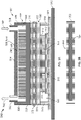
- FIG. 1 illustrates an example system 100 that includes a server rack 105, e.g., a 13 inch or 19 inch server rack, and multiple server rack sub-assemblies 110 mounted within the rack 105.
- server rack 105 may be one of a number of server racks within the system 100, which may include a server farm or a co-location facility that contains various rack mounted computer systems.
- multiple server rack sub-assemblies 110 are illustrated as mounted within the rack 105, there might be only a single server rack sub-assembly.
- the server rack 105 defines multiple slots 107 that are arranged in an orderly and repeating fashion within the server rack 105, and each slot 107 is a space in the rack into which a corresponding server rack sub-assembly 110 can be placed and removed.
- the server rack sub-assembly can be supported on rails 112 that project from opposite sides of the rack 105, and which can define the position of the slots 107.
- the slots 107, and the server rack sub-assemblies 110 can be oriented with the illustrated horizontal arrangement (with respect to gravity).
- the slots 107, and the server rack sub-assemblies 110 can be oriented vertically (with respect to gravity). Where the slots are oriented horizontally, they may be stacked vertically in the rack 105, and where the slots are oriented vertically, they may be stacked horizontally in the rack 105.
- Server rack 105 may provide data processing and storage capacity.
- a data center may be connected to a network, and may receive and respond to various requests from the network to retrieve, process, and/or store data.
- the server rack 105 typically facilitates the communication of information over a network with user interfaces generated by web browser applications of users who request services provided by applications running on computers in the datacenter.
- the server rack 105 may provide or help provide a user who is using a web browser to access web sites on the Internet or the World Wide Web.
- the server rack sub-assembly 110 may be one of a variety of structures that can be mounted in a server rack.
- the server rack sub-assembly 110 may be a "tray" or tray assembly that can be slidably inserted into the server rack 105.
- the term "tray” is not limited to any particular arrangement, but instead applies to the motherboard or other relatively flat structures appurtenant to a motherboard for supporting the motherboard in position in a rack structure.
- the server rack sub-assembly 110 may be a server tray package, server chassis, or server container (e.g., server box).
- the server rack sub-assembly 110 may be a hard drive cage.
- FIG. 2 illustrates a schematic cross-sectional side view of an example implementation of a server tray package 200 that includes a liquid cold plate assembly 201.
- the server tray package 200 may be used as one or more of the server rack sub-assemblies 110 shown in FIG. 1 .
- the server tray package 200 includes a printed circuit board 202, e.g., motherboard 202, that supports one or more data center electronic devices; in this example, two or more memory modules 214 and one or more processing devices 216 (e.g., one or more application-specific integrated circuits (ASIC)).
- ASIC application-specific integrated circuits
- the motherboard 202 may be mounted on a frame (not shown), which can include or simply be a flat structure that can be grasped by technicians for moving the motherboard 202 into place and holding it in position within the rack 105.
- the server tray package 200 may be mounted horizontally in the server rack 105 such as by sliding the frame into the slot 107 and over a pair of rails in the rack 105 on opposed sides of the server tray package 200 - much like sliding a lunch tray into a cafeteria rack.
- the frame can extend below the motherboard 202 or can have other forms (e.g., by implementing it as a peripheral frame around the motherboard 202) or may be eliminated so that the motherboard itself is located in, e.g., slidably engages, the rack 105.
- the frame can be a flat plate or include one or more side walls that project upwardly from the edges of the flat plate, and the flat plate could be the floor of a closed-top or open-top box or cage.
- one motherboard 202 is mounted on a frame; alternatively, multiple motherboards 202 may be mounted on a frame, depending on the needs of the particular application.
- the one or more fans (not shown) can be placed on the motherboard 202 or a frame so that air enters at the front edge of the server tray package 200, closer to the front of the rack 105 when the server tray package 200 is installed in the rack 105, flows over the motherboard 202, over some of the data center electronic components on the motherboard 202, and is exhausted from the server tray package 200 at the back edge, closer to the back of the rack 105 when the server tray package 200 is installed in the rack 105.
- the one or more fans can be secured to the motherboard 202 or a frame by brackets.
- a substrate 204 and an interposer 212 are positioned between the data center electronic devices 214 and 216 and the motherboard 202.
- the substrate 204 provides an interface between one or more of the data center electronic devices (e.g., the processing device 216) and the motherboard 202, such as through pins that provide electrical and communication interfaces.
- the substrate 204 also, in this example, may provide a mounting location for one or more components of the liquid cold plate assembly 201.
- the interposer 212 for example, provides a high bandwidth connection between the data center electronic devices, such as between the memory modules 214 and the processing device 216.
- the liquid cold plate assembly 201 includes a top portion 222, also referred to as a top hat 222, and a base portion 206.
- the base portion 206 includes a lid 208 that defines a top surface of the base portion 206 and sides 210 that couple the lid 208 to the substrate 204.
- the lid 208 and the sides 210 define or enclose a volume 203 in which the interposer 212 and the data center electronic devices 214 and 216 (mounted thereon) are positioned in the server tray package 200.
- a thermal interface material 218 (e.g., a phase change material or otherwise thermally conductive material) is contactingly positioned between a bottom side of the lid 208 and the data center electronic devices 214 and 216 to provide a conductive heat transfer interface between these components.
- the top hat 222 is mounted to a top surface of the lid 208 through another thermal interface material 220 (e.g., a phase change material or otherwise thermally conductive material) that provides a conductive heat transfer interface between a bottom 228 of the top hat 222 and the lid 208 of the base portion 206.
- the top hat 222 includes a cap 224 that is connected to the bottom 228 through sides 226.
- the cap 224, sides 226, and bottom 228 define a volume 234 through which a flow of a cooling liquid may be circulated.
- the cap 224 includes a cooling liquid inlet 230 through which a supply 240 of cooling liquid may enter.
- the cap 224 also includes a cooling liquid outlet 232 through which a return 242 of cooling liquid may exit.
- the volume 234 defines or includes a cooling liquid flow path between the inlet 230 and the outlet 232.
- one or more heat transfer surfaces 236 e.g., fins, undulations, ridges, or other extended surfaces that increase a heat transfer area
- the heat transfer surfaces 236 define channels 238, for example, through which the cooling liquid may be circulated to increase an amount of heat transferred from the data center electronic devices 214 and 216 to the cooling liquid (e.g., relative to an amount transferred in an implementation of the server tray package 200 that does not include the heat transfer surfaces 236).
- Alternative implementations of the server tray package 200 may include multiple inlets 230, multiple outlets 232, or may not include the heat transfer surfaces 236.
- the server tray package 200 may be deployed, for example, in a data center server rack 105 in a data center.
- the processing device 216 and memory modules 214 generate heat that may need to be dissipated or removed from the server tray package 200 (e.g., for proper operation of the server tray package 200).
- Heat generated by the processing device 216 and memory modules 214 is transferred through the thermal interface material 218 and to the lid 208 of the base portion 206 of the liquid cold plate assembly 201.
- the transferred heat is further transferred from the lid 208, through the thermal interface material 220, and to the bottom 228 of the top hat 222.
- one or more components of the liquid cold plate assembly 201 may be formed or made from a thermally conductive material, such as copper, aluminum, a combination of copper and aluminum, or other thermally conductive materials.
- the cooling liquid may be a chilled water or glycol, such as from one or more chillers fluidly coupled to the server tray package 200.
- the cooling liquid may be a condenser water or other evaporatively-cooled liquid (e.g., without mechanical refrigeration).
- the cooling liquid may be a dielectric single or two-phase fluid.
- the cooling liquid supply 240 may be at an appropriate temperature and flow rate to remove a desired amount of heat from the data center electronic devices 214 and 216.
- heat is transferred directly from the bottom 228 to the cooling liquid supply 240. Heat may also be transferred from the bottom 228, through one or more heat transfer surfaces 236, and then to the cooling liquid supply 240 that flows through channels 238.
- the heated cooling liquid supply 240 is circulated to the outlet 232 and exits the top hat 222 as the cooling liquid return 242 (e.g., that is at a higher temperature than the cooling liquid supply 240).
- the cooling liquid return 242 is circulated back, e.g., to a source of the cooling liquid, to expel the heat (e.g., in a chiller, cooling tower, or other heat exchanger) from the return 242.
- FIG. 3A illustrates a schematic cross-sectional side view of another example implementation of a server tray package 300 that includes a liquid cold plate assembly 301 and a vapor chamber 350.
- the server tray package 300 may be used as one or more of the server rack sub-assemblies 110 shown in FIG. 1 .
- the server tray package 300 includes a printed circuit board 302, e.g., motherboard 302, that supports one or more data center electronic devices; in this example, two or more memory modules 314 and one or more processing devices 316 (e.g., one or more application-specific integrated circuits (ASIC)).
- ASIC application-specific integrated circuits
- the motherboard 302 may be mounted on a frame (not shown), which can include or simply be a flat structure that can be grasped by technicians for moving the motherboard 302 into place and holding it in position within the rack 105.
- the server tray package 300 may be mounted horizontally in the server rack 105 such as by sliding the frame into the slot 107 and over a pair of rails in the rack 105 on opposed sides of the server tray package 300 - much like sliding a lunch tray into a cafeteria rack.
- the frame can extend below the motherboard 302 or can have other forms (e.g., by implementing it as a peripheral frame around the motherboard 302) or may be eliminated so that the motherboard itself is located in, e.g., slidably engages, the rack 105.
- the frame can be a flat plate or include one or more side walls that project upwardly from the edges of the flat plate, and the flat plate could be the floor of a closed-top or open-top box or cage.
- one motherboard 302 is mounted on a frame; alternatively, multiple motherboards 302 may be mounted on a frame, depending on the needs of the particular application.
- the one or more fans (not shown) can be placed on the motherboard 302 or a frame so that air enters at the front edge of the server tray package 300, closer to the front of the rack 105 when the server tray package 300 is installed in the rack 105, flows over the motherboard 302, over some of the data center electronic components on the motherboard 302, and is exhausted from the server tray package 300 at the back edge, closer to the back of the rack 105 when the server tray package 300 is installed in the rack 105.
- the one or more fans can be secured to the motherboard 302 or a frame by brackets.
- a substrate 304 and an interposer 312 are positioned between the data center electronic devices 314 and 316 and the motherboard 302.
- the substrate 304 provides an interface between one or more of the data center electronic devices (e.g., the processing device 316) and the motherboard 302, such as through pins that provide electrical and communication interfaces.
- the substrate 304 also, in this example, may provide a mounting location for one or more components of the liquid cold plate assembly 301.
- the liquid cold plate assembly 301 includes a top portion 322, also referred to as a top hat 322, and a base portion 306.
- the base portion 306 includes a lid 308 that defines a top surface of the base portion 306 and sides 310 that couple the lid 308 to the substrate 304.
- the lid 308 and the sides 310 define or enclose a volume 303 in which the interposer 312 and the data center electronic devices 314 and 316 (mounted thereon) are positioned in the server tray package 300.
- a thermal interface material 318 (e.g., a phase change material or otherwise thermally conductive material) is contactingly positioned between a bottom side of the lid 308 and the data center electronic devices 314 and 316 to provide a conductive heat transfer interface between these components.
- the top hat 322 is mounted to a vapor chamber 350 through another thermal interface material 320 (e.g., a phase change material or otherwise thermally conductive material) that provides a conductive heat transfer interface between a bottom 328 of the top hat 322 and the vapor chamber 350.
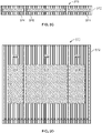
- FIG. 3B this figure illustrates a schematic cross-sectional side view of an example implementation of the vapor chamber 350.
- the vapor chamber 350 includes a housing that contains a heat transfer fluid 354 (e.g., water, refrigerant, or other fluid that boils in response to heat being received).
- the vapor chamber 350 includes a single chamber within the housing 352 that encloses the fluid 354.
- the vapor chamber 350 may include boiling enhancements (e.g., fins or otherwise) within the chamber (e.g., on a bottom inner surface) to increase heat transfer to the fluid 354.
- the vapor chamber 350 may also include condensing enhancements (e.g., a wicking structure) within the chamber (e.g., on a top inner surface) to allow for better heat transfer from the fluid 354 to the bottom 328 of the top hat 322.
- the vapor chamber 350 (with a single chamber and fluid 354) sits on top of the data center electronic devices 314 and 316.
- one or more of the electronic devices e.g., processor 316
- the vapor chamber 350 may eliminate or help eliminate hot spots caused by the processor 316 by distributing the heat from the processor 316 throughout the chamber 350 (e.g., into the fluid 354).
- an even or substantially even (per unit area) transfer of heat from the vapor chamber to the top hat assembly 322 may be achieved.
- the vapor chamber 350 is mounted to the lid 308 of the base portion 306 through another thermal interface material 353 (e.g., a phase change material or otherwise thermally conductive material).
- a thermal interface material 353 e.g., a phase change material or otherwise thermally conductive material.
- the top hat 322 includes a cap 324 that is connected to the bottom 328 through sides 326.
- the cap 324, sides 326, and bottom 328 define a volume 334 through which a flow of a cooling liquid may be circulated.
- the cap 324 includes a cooling liquid inlet 330 through which a supply 340 of cooling liquid may enter.
- the cap 324 also includes a cooling liquid outlet 332 through which a return 342 of cooling liquid may exit.
- the volume 334 defines or includes a cooling liquid flow path between the inlet 330 and the outlet 332.
- one or more heat transfer surfaces 336 e.g., fins, undulations, ridges, or other extended surfaces that increase a heat transfer area
- the heat transfer surfaces 336 define channels 338, for example, through which the cooling liquid may be circulated to increase an amount of heat transferred from the data center electronic devices 314 and 316 to the cooling liquid (e.g., relative to an amount transferred in an implementation of the server tray package 300 that does not include the heat transfer surfaces 336).
- Alternative implementations of the server tray package 300 may include multiple inlets 330, multiple outlets 332, or may not include the heat transfer surfaces 336.
- the server tray package 300 may be deployed, for example, in a data center server rack 105 in a data center.
- the processing device 316 and memory modules 314 generate heat that may need to be dissipated or removed from the server tray package 300 (e.g., for proper operation of the server tray package 300).
- Heat generated by the processing device 316 and memory modules 314 is transferred through the thermal interface material 318 and to the lid 308 of the base portion 306 of the liquid cold plate assembly 301. The transferred heat is further transferred from the lid 308, through the thermal interface material 320, and to the vapor chamber 350.
- the fluid 354 may boil or vaporize.
- the boiling or vaporized fluid 354 naturally circulates toward a top of the vapor chamber 350, where heat is transferred to the bottom 328 of the top hat 322.
- the vaporized or boiled fluid 354 condenses back into liquid form and falls back to the bottom of the vapor chamber 350.
- the cooling liquid may be a chilled water or glycol, such as from one or more chillers fluidly coupled to the server tray package 300.
- the cooling liquid may be a condenser water or other evaporatively-cooled liquid (e.g., without mechanical refrigeration).
- the cooling liquid may be a dielectric single or two-phase fluid.
- the cooling liquid supply 340 may be at an appropriate temperature and flow rate to remove a desired amount of heat from the data center electronic devices 314 and 316.
- heat is transferred directly from the bottom 328 to the cooling liquid supply 340. Heat may also be transferred from the bottom 328, through one or more heat transfer surfaces 336, and then to the cooling liquid supply 340 that flows through channels 338.
- the heated cooling liquid supply 340 is circulated to the outlet 332 and exits the top hat 322 as the cooling liquid return 342 (e.g., that is at a higher temperature than the cooling liquid supply 340).
- the cooling liquid return 342 is circulated back, e.g., to a source of the cooling liquid, to expel the heat (e.g., in a chiller, cooling tower, or other heat exchanger) from the return 342.
- FIGS. 3C and 3D illustrate schematic side and top views of another example implementation of a vapor chamber 370 that can be used in a liquid cold plate assembly in a server tray package, such as the server tray package 300.
- vapor chamber 370 has multiple sub-chambers; in this example, three sub-chambers split between two sub-chambers 374 and a sub-chamber 376.
- Heat transfer fluid may be contained in each sub-chamber 374 and 376.
- the sub-chambers 374 may be differently sized (e.g., length and width) than the sub-chamber 376. As shown in FIG.
- each sub-chamber may be tailored, e.g., according to the heat power output of the particular data center electronic device over which it sits.
- the type of heat transfer fluid contained in, or dimensions of, each sub-chamber can be tailored to meet the heat transfer requirements to remove heat from the particular data center electronic device.
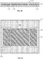
- FIG. 4A illustrates a schematic cross-sectional side view of another example implementation of a server tray package 400 that includes a liquid cold plate assembly 401 and a vapor chamber 450.
- the server tray package 400 may be used as one or more of the server rack sub-assemblies 110 shown in FIG. 1 .
- the server tray package 400 includes a printed circuit board 402, e.g., motherboard 402, that supports one or more data center electronic devices; in this example, two or more memory modules 414 and one or more processing devices 416 (e.g., one or more application-specific integrated circuits (ASIC)).
- ASIC application-specific integrated circuits
- the motherboard 402 may be mounted on a frame (not shown), which can include or simply be a flat structure that can be grasped by technicians for moving the motherboard 402 into place and holding it in position within the rack 105.
- the server tray package 400 may be mounted horizontally in the server rack 105 such as by sliding the frame into the slot 107 and over a pair of rails in the rack 105 on opposed sides of the server tray package 400 - much like sliding a lunch tray into a cafeteria rack.
- the frame can extend below the motherboard 402 or can have other forms (e.g., by implementing it as a peripheral frame around the motherboard 402) or may be eliminated so that the motherboard itself is located in, e.g., slidably engages, the rack 105.
- the frame can be a flat plate or include one or more side walls that project upwardly from the edges of the flat plate, and the flat plate could be the floor of a closed-top or open-top box or cage.
- one motherboard 402 is mounted on a frame; alternatively, multiple motherboards 402 may be mounted on a frame, depending on the needs of the particular application.
- the one or more fans (not shown) can be placed on the motherboard 402 or a frame so that air enters at the front edge of the server tray package 400, closer to the front of the rack 105 when the server tray package 400 is installed in the rack 105, flows over the motherboard 402, over some of the data center electronic components on the motherboard 402, and is exhausted from the server tray package 400 at the back edge, closer to the back of the rack 105 when the server tray package 400 is installed in the rack 105.
- the one or more fans can be secured to the motherboard 402 or a frame by brackets.
- a substrate 404 and an interposer 412 are positioned between the data center electronic devices 414 and 416 and the motherboard 402.
- the substrate 404 provides an interface between one or more of the data center electronic devices (e.g., the processing device 416) and the motherboard 402, such as through pins that provide electrical and communication interfaces.
- the substrate 404 also, in this example, may provide a mounting location for one or more components of the liquid cold plate assembly 401.
- the interposer 412 for example, provides a high bandwidth connection between the data center electronic devices, such as between the memory modules 414 and the processing device 416.
- the liquid cold plate assembly 401 includes a top portion 422, also referred to as a top hat 422, and a base portion 406.
- the base portion 406 includes a lid 408 that defines a top surface of the base portion 406 and sides 410 that couple the lid 408 to the substrate 404.
- the lid 408 and the sides 410 define or enclose a volume 403 in which the interposer 412 and the data center electronic devices 414 and 416 (mounted thereon) are positioned in the server tray package 400.
- a thermal interface material 418 (e.g., a phase change material or otherwise thermally conductive material) is contactingly positioned between a bottom side of the lid 408 and the data center electronic devices 414 and 416 to provide a conductive heat transfer interface between these components.
- the top hat 422 is mounted to a vapor chamber 450 through another thermal interface material 420 (e.g., a phase change material or otherwise thermally conductive material) that provides a conductive heat transfer interface between a bottom 428 of the top hat 422 and the vapor chamber 450.
- Vapor chamber 450 in this example, can be a single chamber vapor chamber (e.g., as shown in FIG. 3B ) or can be a multi-chamber vapor chamber (as shown in FIGS. 3C-3D or 4B-4C ). Further, as shown in this example, the top hat 422 and vapor chamber 450 may be sized larger (e.g., length and width) than the base portion 406.
- the vapor chamber 450 and top hat 422 may overhang on two or more sides (two sides shown in FIG. 4A ) of the lid 408 of the base portion 406.
- This vapor chamber 450/top hat 422 combination may provide for better heat transfer from the data center electronic devices 414 and 416 as compared to a vapor chamber/top hat combination that has dimensions (e.g., length and width) similar to those of the lid 408.
- dimensions e.g., length and width
- one or more of the electronic devices may generate more heat than the other electronic devices (e.g., memory modules 414).
- the vapor chamber 450 may eliminate or help eliminate hot spots caused by the processor 416 by distributing the heat from the processor 416 throughout the chamber 450 (e.g., into the fluid).
- an even or substantially even (per unit area) transfer of heat from the vapor chamber to the top hat assembly 422 may be achieved.
- the vapor chamber 450 is mounted to the lid 408 of the base portion 406 through another thermal interface material 453 (e.g., a phase change material or otherwise thermally conductive material).
- a thermal interface material 453 e.g., a phase change material or otherwise thermally conductive material.
- the top hat 422 includes a cap 424 that is connected to the bottom 428 through sides 426.
- the cap 424, sides 426, and bottom 428 define a volume 434 through which a flow of a cooling liquid may be circulated.
- the cap 424 includes a cooling liquid inlet 430 through which a supply 440 of cooling liquid may enter.
- the cap 424 also includes a cooling liquid outlet 432 through which a return 442 of cooling liquid may exit.
- the volume 434 defines or includes a cooling liquid flow path between the inlet 430 and the outlet 432.
- one or more heat transfer surfaces 436 are positioned in the volume 434.
- the heat transfer surfaces 436 define channels 438, for example, through which the cooling liquid may be circulated to increase an amount of heat transferred from the data center electronic devices 414 and 416 to the cooling liquid (e.g., relative to an amount transferred in an implementation of the server tray package 400 that does not include the heat transfer surfaces 436).
- Alternative implementations of the server tray package 400 may include multiple inlets 430, multiple outlets 432, or may not include the heat transfer surfaces 436.
- the server tray package 400 may be deployed, for example, in a data center server rack 105 in a data center.
- the processing device 416 and memory modules 414 generate heat that may need to be dissipated or removed from the server tray package 400 (e.g., for proper operation of the server tray package 400).
- Heat generated by the processing device 416 and memory modules 414 is transferred through the thermal interface material 418 and to the lid 408 of the base portion 406 of the liquid cold plate assembly 401. The transferred heat is further transferred from the lid 408, through the thermal interface material 420, and to the vapor chamber 450.
- the fluid may boil or vaporize.
- the boiling or vaporized fluid naturally circulates toward a top of the vapor chamber 450, where heat is transferred to the bottom 428 of the top hat 422.
- the vaporized or boiled fluid condenses back into liquid form and falls back to the bottom of the vapor chamber 450.
- the cooling liquid may be a chilled water or glycol, such as from one or more chillers fluidly coupled to the server tray package 400.
- the cooling liquid may be a condenser water or other evaporatively-cooled liquid (e.g., without mechanical refrigeration).
- the cooling liquid may be a dielectric single or two-phase fluid.
- the cooling liquid supply 440 may be at an appropriate temperature and flow rate to remove a desired amount of heat from the data center electronic devices 414 and 416.
- heat is transferred directly from the bottom 428 to the cooling liquid supply 440. Heat may also be transferred from the bottom 428, through one or more heat transfer surfaces 436, and then to the cooling liquid supply 440 that flows through channels 438.
- the heated cooling liquid supply 440 is circulated to the outlet 432 and exits the top hat 422 as the cooling liquid return 442 (e.g., that is at a higher temperature than the cooling liquid supply 440).
- the cooling liquid return 442 is circulated back, e.g., to a source of the cooling liquid, to expel the heat (e.g., in a chiller, cooling tower, or other heat exchanger) from the return 442.
- FIGS. 4B and 4C illustrate schematic side and top views of another example implementation of a vapor chamber 470 that can be used in a liquid cold plate assembly in a server tray package, such as server tray package 400.
- vapor chamber 470 has multiple sub-chambers; in this example, three sub-chambers split between two sub-chambers 474 and a sub-chamber 476.
- Heat transfer fluid may be contained in each sub-chamber 474 and 476.
- the sub-chambers 474 may be differently sized (e.g., length and width and even shape) than the sub-chamber 476. As shown in FIG.
- the larger, single sub-chamber 476 may sit, when the vapor chamber 470 is positioned on the lid 408, over the processor 416 as well as extending adjacent the memory modules 414 (e.g., in an "I" or "H” shape).
- the two sub-chambers 474 may sit over the memory modules 414 and be rectangular in shape in this example.
- each sub-chamber may be tailored, e.g., according to the heat power output of the particular data center electronic device over which it sits.
- the type of heat transfer fluid contained in, or dimensions or shape of, each sub-chamber can be tailored to meet the heat transfer requirements to remove heat from the particular data center electronic device.
- FIG. 5 illustrates a schematic cross-sectional side view of another example implementation of a server tray package 500 that includes a liquid cold plate assembly 501 and a vapor chamber 550.
- the server tray package 500 may be used as one or more of the server rack sub-assemblies 110 shown in FIG. 1 .
- the server tray package 500 includes a printed circuit board 502, e.g., motherboard 502, that supports one or more data center electronic devices; in this example, two or more memory modules 514 and one or more processing devices 516 (e.g., one or more application-specific integrated circuits (ASIC)).
- ASIC application-specific integrated circuits
- the motherboard 502 may be mounted on a frame (not shown), which can include or simply be a flat structure that can be grasped by technicians for moving the motherboard 502 into place and holding it in position within the rack 105.
- the server tray package 500 may be mounted horizontally in the server rack 105 such as by sliding the frame into the slot 107 and over a pair of rails in the rack 105 on opposed sides of the server tray package 500 - much like sliding a lunch tray into a cafeteria rack.
- the frame can extend below the motherboard 502 or can have other forms (e.g., by implementing it as a peripheral frame around the motherboard 502) or may be eliminated so that the motherboard itself is located in, e.g., slidably engages, the rack 105.
- the frame can be a flat plate or include one or more side walls that project upwardly from the edges of the flat plate, and the flat plate could be the floor of a closed-top or open-top box or cage.
- one motherboard 502 is mounted on a frame; alternatively, multiple motherboards 502 may be mounted on a frame, depending on the needs of the particular application.
- the one or more fans (not shown) can be placed on the motherboard 502 or a frame so that air enters at the front edge of the server tray package 500, closer to the front of the rack 105 when the server tray package 500 is installed in the rack 105, flows over the motherboard 502, over some of the data center electronic components on the motherboard 502, and is exhausted from the server tray package 500 at the back edge, closer to the back of the rack 105 when the server tray package 500 is installed in the rack 105.
- the one or more fans can be secured to the motherboard 502 or a frame by brackets.
- a substrate 504 and an interposer 512 are positioned between the data center electronic devices 514 and 516 and the motherboard 502.
- the substrate 504 provides an interface between one or more of the data center electronic devices (e.g., the processing device 516) and the motherboard 502, such as through pins that provide electrical and communication interfaces.
- the substrate 504 also, in this example, may provide a mounting location for one or more components of the liquid cold plate assembly 501.
- the interposer 512 for example, provides a high bandwidth connection between the data center electronic devices, such as between the memory modules 514 and the processing device 516.
- the liquid cold plate assembly 501 includes a top portion 522, also referred to as a top hat 522, and a base portion 506.
- the base portion 506 includes a lid 508 that defines a top surface of the base portion 506 and sides 510 that couple the lid 508 to the substrate 504.
- the lid 508 and the sides 510 define or enclose a volume 503 in which the interposer 512 and the data center electronic devices 514 and 516 (mounted thereon) are positioned in the server tray package 500.
- a thermal interface material 518 (e.g., a phase change material or otherwise thermally conductive material) is contactingly positioned between a bottom side of the lid 508 and the data center electronic devices 514 and 516 to provide a conductive heat transfer interface between these components.
- the top hat 522 includes (is integrated with) a vapor chamber 550.
- the vapor chamber 550 may be a single chamber vapor chamber (e.g., as shown in FIG. 3B ) or a multi-chamber vapor chamber (e.g., as shown in FIGS. 3C-3D or 4B-4C ).
- the vapor chamber 550 sits on top of the data center electronic devices 514 and 516.
- one or more of the electronic devices e.g., processor 516) may generate more heat than the other electronic devices (e.g., memory modules 514).
- the vapor chamber 550 may eliminate or help eliminate hot spots caused by the processor 516 by distributing the heat from the processor 516 throughout the chamber 550 (e.g., into the fluid).
- the vapor chamber 550 may eliminate or help eliminate hot spots caused by the processor 516 by distributing the heat from the processor 516 throughout the chamber 550 (e.g., into the fluid).
- an even or substantially even (per unit area) transfer of heat from the vapor chamber to the top hat assembly 522 may be achieved.
- the top hat 522 that includes the vapor chamber 550 is mounted to the lid 508 of the base portion 506 through another thermal interface material 520 (e.g., a phase change material or otherwise thermally conductive material).
- a thermal interface material 520 e.g., a phase change material or otherwise thermally conductive material.
- the top hat 522 includes a cap 524 that is connected to a vapor chamber 550 through sides 526.
- the cap 524, sides 526, and vapor chamber 550 define a volume 534 through which a flow of a cooling liquid may be circulated.
- the cap 524 includes a cooling liquid inlet 530 through which a supply 540 of cooling liquid may enter.
- the cap 524 also includes a cooling liquid outlet 532 through which a return 542 of cooling liquid may exit.
- the volume 534 defines or includes a cooling liquid flow path between the inlet 530 and the outlet 532.
- one or more heat transfer surfaces 536 are positioned in the volume 534.
- the heat transfer surfaces 536 define channels 538, for example, through which the cooling liquid may be circulated to increase an amount of heat transferred from the data center electronic devices 514 and 516 to the cooling liquid (e.g., relative to an amount transferred in an implementation of the server tray package 500 that does not include the heat transfer surfaces 536).
- Alternative implementations of the server tray package 500 may include multiple inlets 530, multiple outlets 532, or may not include the heat transfer surfaces 536.
- the server tray package 500 may be deployed, for example, in a data center server rack 105 in a data center.
- the processing device 516 and memory modules 514 generate heat that may need to be dissipated or removed from the server tray package 500 (e.g., for proper operation of the server tray package 500).
- Heat generated by the processing device 516 and memory modules 514 is transferred through the thermal interface material 518 and to the lid 508 of the base portion 506 of the liquid cold plate assembly 501. The transferred heat is further transferred from the lid 508, through the thermal interface material 520, and to the vapor chamber 550.
- the fluid may boil or vaporize.
- the boiling or vaporized fluid naturally circulates toward a top of the vapor chamber 550, where heat is transferred to the supply 540 of the cooling liquid.
- the vaporized or boiled fluid condenses back into liquid form and falls back to the bottom of the vapor chamber 550.
- the cooling liquid may be a chilled water or glycol, such as from one or more chillers fluidly coupled to the server tray package 500.
- the cooling liquid may be a condenser water or other evaporatively-cooled liquid (e.g., without mechanical refrigeration).
- the cooling liquid may be a dielectric single or two-phase fluid.
- the cooling liquid supply 540 may be at an appropriate temperature and flow rate to remove a desired amount of heat from the data center electronic devices 514 and 516.
- heat is transferred directly from the vapor chamber 550 (the housing) to the cooling liquid supply 540. Heat may also be transferred from the housing of the vapor chamber 550, through one or more heat transfer surfaces 536, and then to the cooling liquid supply 540 that flows through channels 538.
- the heated cooling liquid supply 540 is circulated to the outlet 532 and exits the top hat 522 as the cooling liquid return 542 (e.g., that is at a higher temperature than the cooling liquid supply 540).
- the cooling liquid return 542 is circulated back, e.g., to a source of the cooling liquid, to expel the heat (e.g., in a chiller, cooling tower, or other heat exchanger) from the return 542.
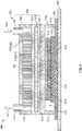
- FIG. 6 illustrates a schematic cross-sectional side view of another example implementation of a server tray package 600 that includes a liquid cold plate assembly 601 and a vapor chamber 650.
- the server tray package 600 may be used as one or more of the server rack sub-assemblies 110 shown in FIG. 1 .
- the server tray package 600 includes a printed circuit board 602, e.g., motherboard 602, that supports one or more data center electronic devices; in this example, two or more memory modules 614 and one or more processing devices 616 (e.g., one or more application-specific integrated circuits (ASIC)).
- ASIC application-specific integrated circuits
- the motherboard 602 may be mounted on a frame (not shown), which can include or simply be a flat structure that can be grasped by technicians for moving the motherboard 602 into place and holding it in position within the rack 105.
- the server tray package 600 may be mounted horizontally in the server rack 105 such as by sliding the frame into the slot 107 and over a pair of rails in the rack 105 on opposed sides of the server tray package 600 - much like sliding a lunch tray into a cafeteria rack.
- the frame can extend below the motherboard 602 or can have other forms (e.g., by implementing it as a peripheral frame around the motherboard 602) or may be eliminated so that the motherboard itself is located in, e.g., slidably engages, the rack 105.
- the frame can be a flat plate or include one or more side walls that project upwardly from the edges of the flat plate, and the flat plate could be the floor of a closed-top or open-top box or cage.
- one motherboard 602 is mounted on a frame; alternatively, multiple motherboards 602 may be mounted on a frame, depending on the needs of the particular application.
- the one or more fans (not shown) can be placed on the motherboard 602 or a frame so that air enters at the front edge of the server tray package 600, closer to the front of the rack 105 when the server tray package 600 is installed in the rack 105, flows over the motherboard 602, over some of the data center electronic components on the motherboard 602, and is exhausted from the server tray package 600 at the back edge, closer to the back of the rack 105 when the server tray package 600 is installed in the rack 105.
- the one or more fans can be secured to the motherboard 602 or a frame by brackets.
- a substrate 604 and an interposer 612 are positioned between the data center electronic devices 614 and 616 and the motherboard 602.
- the substrate 604 provides an interface between one or more of the data center electronic devices (e.g., the processing device 616) and the motherboard 602, such as through pins that provide electrical and communication interfaces.
- the substrate 604 also, in this example, may provide a mounting location for one or more components of the liquid cold plate assembly 601.
- the interposer 612 for example, provides a high bandwidth connection between the data center electronic devices, such as between the memory modules 614 and the processing device 616.
- the liquid cold plate assembly 601 includes a top portion 622, also referred to as a top hat 622, and a base portion 606.
- the base portion 606 includes a vapor chamber 650 integrated therein that defines a top surface of the base portion 606 and sides 610 that couple the vapor chamber 650 to the substrate 604.
- the vapor chamber 650 and the sides 610 define or enclose a volume 603 in which the interposer 612 and the data center electronic devices 614 and 616 (mounted thereon) are positioned in the server tray package 600.
- a thermal interface material 618 (e.g., a phase change material or otherwise thermally conductive material) is contactingly positioned between a bottom side of the vapor chamber 650 and the data center electronic devices 614 and 616 to provide a conductive heat transfer interface between these components.
- the top hat 622 is mounted to the vapor chamber 650 through another thermal interface material 620 (e.g., a phase change material or otherwise thermally conductive material) that provides a conductive heat transfer interface between a bottom 628 of the top hat 622 and the vapor chamber 650.
- the vapor chamber 650 may be a single chamber vapor chamber (e.g., as shown in FIG. 3B ) or a multi-chamber vapor chamber (e.g., as shown in FIGS. 3C-3D or 4B-4C ). As shown in this example, the vapor chamber 650 sits on top of the data center electronic devices 614 and 616.
- one or more of the electronic devices may generate more heat than the other electronic devices (e.g., memory modules 614).
- the vapor chamber 650 may eliminate or help eliminate hot spots caused by the processor 616 by distributing the heat from the processor 616 throughout the chamber 650 (e.g., into the fluid).
- an even or substantially even (per unit area) transfer of heat from the vapor chamber to the top hat 622 may be achieved.
- the top hat 622 includes a cap 624 that is connected to the bottom 628 through sides 626.
- the cap 624, sides 626, and bottom 628 define a volume 634 through which a flow of a cooling liquid may be circulated.
- the cap 624 includes a cooling liquid inlet 630 through which a supply 640 of cooling liquid may enter.
- the cap 624 also includes a cooling liquid outlet 632 through which a return 642 of cooling liquid may exit.
- the volume 634 defines or includes a cooling liquid flow path between the inlet 630 and the outlet 632.
- one or more heat transfer surfaces 636 are positioned in the volume 634.
- the heat transfer surfaces 636 define channels 638, for example, through which the cooling liquid may be circulated to increase an amount of heat transferred from the data center electronic devices 614 and 616 to the cooling liquid (e.g., relative to an amount transferred in an implementation of the server tray package 600 that does not include the heat transfer surfaces 636).
- Alternative implementations of the server tray package 600 may include multiple inlets 630, multiple outlets 632, or may not include the heat transfer surfaces 636.
- the server tray package 600 may be deployed, for example, in a data center server rack 105 in a data center.
- the processing device 616 and memory modules 614 generate heat that may need to be dissipated or removed from the server tray package 600 (e.g., for proper operation of the server tray package 600).
- Heat generated by the processing device 616 and memory modules 614 is transferred through the thermal interface material 618 and to the vapor chamber 650 of the base portion 606 of the liquid cold plate assembly 601.
- the transferred heat is transferred through the thermal interface material 620 and to the fluid of the vapor chamber 650. As heat is transferred into the fluid, the fluid may boil or vaporize.
- the boiling or vaporized fluid naturally circulates toward a top of the vapor chamber 650, where heat is transferred to the bottom 628 of the top hat 622. As heat is transferred to the bottom 628, the vaporized or boiled fluid condenses back into liquid form and falls back to the bottom of the vapor chamber 650.
- the cooling liquid may be a chilled water or glycol, such as from one or more chillers fluidly coupled to the server tray package 600.
- the cooling liquid may be a condenser water or other evaporatively-cooled liquid (e.g., without mechanical refrigeration).
- the cooling liquid may be a dielectric single or two-phase fluid.
- the cooling liquid supply 640 may be at an appropriate temperature and flow rate to remove a desired amount of heat from the data center electronic devices 614 and 616.
- heat is transferred directly from the bottom 628 to the cooling liquid supply 640. Heat may also be transferred from the bottom 628, through one or more heat transfer surfaces 636, and then to the cooling liquid supply 640 that flows through channels 638.
- the heated cooling liquid supply 640 is circulated to the outlet 632 and exits the top hat 622 as the cooling liquid return 642 (e.g., that is at a higher temperature than the cooling liquid supply 640).
- the cooling liquid return 642 is circulated back, e.g., to a source of the cooling liquid, to expel the heat (e.g., in a chiller, cooling tower, or other heat exchanger) from the return 642.
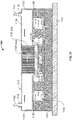
- FIG. 7 illustrates a schematic cross-sectional side view of a portion of an example implementation of a server tray package 700 that includes a liquid cold plate assembly 701 set on a partial lid 706.
- the server tray package 700 may be used as one or more of the server rack sub-assemblies 110 shown in FIG. 1 .
- the server tray package 700 includes a printed circuit board 702, e.g., motherboard 702, that supports one or more data center electronic devices; in this example, two or more voltage regulators 714, two or more capacitors 705, and one or more processing devices 716 (e.g., one or more application-specific integrated circuits (ASIC)).
- ASIC application-specific integrated circuits
- the motherboard 702 may be mounted on a frame (not shown), which can include or simply be a flat structure that can be grasped by technicians for moving the motherboard 702 into place and holding it in position within the rack 105.
- the server tray package 700 may be mounted horizontally in the server rack 105 such as by sliding the frame into the slot 107 and over a pair of rails in the rack 105 on opposed sides of the server tray package 700 - much like sliding a lunch tray into a cafeteria rack.
- the frame can extend below the motherboard 702 or can have other forms (e.g., by implementing it as a peripheral frame around the motherboard 702) or may be eliminated so that the motherboard itself is located in, e.g., slidably engages, the rack 105.
- the frame can be a flat plate or include one or more side walls that project upwardly from the edges of the flat plate, and the flat plate could be the floor of a closed-top or open-top box or cage.
- one motherboard 702 is mounted on a frame; alternatively, multiple motherboards 702 may be mounted on a frame, depending on the needs of the particular application.
- the one or more fans (not shown) can be placed on the motherboard 702 or a frame so that air enters at the front edge of the server tray package 700, closer to the front of the rack 105 when the server tray package 700 is installed in the rack 105, flows over the motherboard 702, over some of the data center electronic components on the motherboard 702, and is exhausted from the server tray package 700 at the back edge, closer to the back of the rack 105 when the server tray package 700 is installed in the rack 105.
- the one or more fans can be secured to the motherboard 702 or a frame by brackets.
- a substrate 704 and one or more interposers 712 are positioned between the data center electronic devices 705, 714, and 716 and the motherboard 702.
- the substrate 704 provides an interface between one or more of the data center electronic devices (e.g., the processing device 716) and the motherboard 702, such as through pins that provide electrical and communication interfaces.
- the substrate 704 also, in this example, may provide a mounting location for one or more components of the liquid cold plate assembly 701.
- the interposer 712 for example, provides a high bandwidth connection between the data center electronic devices, such as between the memory modules 714 and the processing device 716.
- the data center electronic devices 705, 714, and 716 may have different sizes and, more particularly, different heights.
- voltage regulators 714 may be taller (e.g., 2 to 3 times taller), relatively, than the processor 716 (and the capacitors 705).
- the data center electronic devices 705, 714, and 716 may produce different heat outputs during their respective operations.
- the processor 716 may produce much more heat during operation (e.g., at least an order of magnitude more) than the voltage regulators 714.
- the liquid cold plate assembly 701 includes side portions 735 and a base portion 739. As shown, the side portions 735 extend from the base portion 739 and are thinner (e.g., shorter in vertical distance) than the base portion 739. Although not shown, from a top view, the liquid cold plate assembly 701 may be relatively square in shape, with the side portions 735 being part of a perimeter area that circumscribes the base portion 739.
- the lid 706, or partial lid 706, sits on the substrate 704 and includes an aperture through which the base portion 739 may extend when the liquid cold plate assembly 701 rests on the lid 706.
- the partial lid 706 may be a square ring in shape, with the aperture shaped as a square to allow insertion of the base portion 739 of the liquid cold plate assembly when the side portions 735 rest on the partial lid 706.
- the partial lid 706 defines or encloses a volume 703 in which the interposer 712 and the data center electronic devices 705, 714, and 716 (mounted thereon) are positioned in the server tray package 700.
- a thermal interface material 718 e.g., a phase change material or otherwise thermally conductive material
- a thermal interface material 718 is contactingly positioned between a bottom side of the partial lid 706 and the data center electronic devices 714 to provide a conductive heat transfer interface between these components.
- the side portions 735 are mounted to a top surface of the partial lid 706.
- the base 739 e.g., a bottom surface of the base 739
- phase change material 718 or otherwise thermally conductive material
- the liquid cold plate assembly 701 includes a cooling liquid inlet 730 through which a supply 740 of cooling liquid may enter.
- the liquid cold plate assembly 701 also includes a cooling liquid outlet 732 through which a return 742 of cooling liquid may exit.
- a volume 734 defines or includes a cooling liquid flow path between the inlet 730 and the outlet 732.
- one or more heat transfer surfaces 736 e.g., fins, undulations, ridges, or other extended surfaces that increase a heat transfer area
- the heat transfer surfaces 736 extend from at or near a top interior surface of the assembly 701 to at or near a bottom interior surface of the base portion 739 of the assembly 701.
- the heat transfer surfaces 736 define channels 738, for example, through which the cooling liquid may be circulated to increase an amount of heat transferred from the data center electronic devices 714 and 716 to the cooling liquid (e.g., relative to an amount transferred in an implementation of the server tray package 700 that does not include the heat transfer surfaces 736).
- Alternative implementations of the server tray package 700 may include multiple inlets 730, multiple outlets 732, or may not include the heat transfer surfaces 736.
- the server tray package 700 may be deployed, for example, in a data center server rack 105 in a data center.
- the processing device 716 and voltage regulators 714 generate heat that may need to be dissipated or removed from the server tray package 700 (e.g., for proper operation of the server tray package 700).
- Heat generated by the processing device 716 is transferred through the thermal interface material 718 and to the base portion 739 of the liquid cold plate assembly 701.
- Heat generated by the voltage regulators 714 is transferred through the thermal interface material 718, through the partial lid 706, and to the side portions 735 of the liquid cold plate assembly 701.
- one or more components of the liquid cold plate assembly 701 may be formed or made from a thermally conductive material, such as copper, aluminum, a combination of copper and aluminum, or other thermally conductive materials.
- the cooling liquid may be a chilled water or glycol, such as from one or more chillers fluidly coupled to the server tray package 700.
- the cooling liquid may be a condenser water or other evaporatively-cooled liquid (e.g., without mechanical refrigeration).
- the cooling liquid may be a dielectric single or two-phase fluid.
- the cooling liquid supply 740 may be at an appropriate temperature and flow rate to remove a desired amount of heat from the data center electronic devices 714 and 716.
- heat is transferred directly from the base portion 739 to the cooling liquid supply 740.
- Heat may also be transferred from the base portion 739, through one or more heat transfer surfaces 736 (in this example, confined to the base portion 739), and then to the cooling liquid supply 740 that flows through channels 738.
- the heated cooling liquid supply 740 is circulated to the outlet 732 and exits the liquid cold plate assembly 701 as the cooling liquid return 742 (e.g., that is at a higher temperature than the cooling liquid supply 740).
- the cooling liquid return 742 is circulated back, e.g., to a source of the cooling liquid, to expel the heat (e.g., in a chiller, cooling tower, or other heat exchanger) from the return 742.
- FIG. 8 illustrates a schematic cross-sectional side view of a portion of an example implementation of a server tray package 800 that includes a liquid cold plate assembly 801 set on a partial lid 806.
- the server tray package 800 may be used as one or more of the server rack sub-assemblies 110 shown in FIG. 1 .
- the server tray package 800 includes a printed circuit board 802, e.g., motherboard 802, that supports one or more data center electronic devices; in this example, two or more voltage regulators 814, two or more capacitors 805, and one or more processing devices 816 (e.g., one or more application-specific integrated circuits (ASIC)).
- ASIC application-specific integrated circuits
- the motherboard 802 may be mounted on a frame (not shown), which can include or simply be a flat structure that can be grasped by technicians for moving the motherboard 802 into place and holding it in position within the rack 105.
- the server tray package 800 may be mounted horizontally in the server rack 105 such as by sliding the frame into the slot 107 and over a pair of rails in the rack 105 on opposed sides of the server tray package 800 - much like sliding a lunch tray into a cafeteria rack.
- the frame can extend below the motherboard 802 or can have other forms (e.g., by implementing it as a peripheral frame around the motherboard 802) or may be eliminated so that the motherboard itself is located in, e.g., slidably engages, the rack 105.
- the frame can be a flat plate or include one or more side walls that project upwardly from the edges of the flat plate, and the flat plate could be the floor of a closed-top or open-top box or cage.
- one motherboard 802 is mounted on a frame; alternatively, multiple motherboards 802 may be mounted on a frame, depending on the needs of the particular application.
- the one or more fans (not shown) can be placed on the motherboard 802 or a frame so that air enters at the front edge of the server tray package 800, closer to the front of the rack 105 when the server tray package 800 is installed in the rack 105, flows over the motherboard 802, over some of the data center electronic components on the motherboard 802, and is exhausted from the server tray package 800 at the back edge, closer to the back of the rack 105 when the server tray package 800 is installed in the rack 105.
- the one or more fans can be secured to the motherboard 802 or a frame by brackets.
- a substrate 804 and one or more interposers 812 are positioned between the data center electronic devices 805, 814, and 816 and the motherboard 802.
- the substrate 804 provides an interface between one or more of the data center electronic devices (e.g., the processing device 816) and the motherboard 802, such as through pins that provide electrical and communication interfaces.
- the substrate 804 also, in this example, may provide a mounting location for one or more components of the liquid cold plate assembly 801.
- the interposer 812 for example, provides a high bandwidth connection between the data center electronic devices, such as between the memory modules 814 and the processing device 816.
- the data center electronic devices 805, 814, and 816 may have different sizes and, more particularly, different heights.
- voltage regulators 814 may be taller (e.g., 2 to 3 times taller), relatively, than the processor 816 (and the capacitors 805).
- the data center electronic devices 805, 814, and 816 may produce different heat outputs during their respective operations.
- the processor 816 may produce much more heat during operation (e.g., at least an order of magnitude more) than the voltage regulators 814.
- the liquid cold plate assembly 801 includes side portions 835 and a base portion 839. As shown, the side portions 835 extend from the base portion 839 and are thinner (e.g., shorter in vertical distance) than the base portion 839. Although not shown, from a top view, the liquid cold plate assembly 801 may be relatively square in shape, with the side portions 835 being part of a perimeter area that circumscribes the base portion 839.
- the lid 806, or partial lid 806, sits on the substrate 804 and includes an aperture through which the base portion 839 may extend when the liquid cold plate assembly 801 rests on the lid 806.
- the partial lid 806 may be a square ring in shape, with the aperture shaped as a square to allow insertion of the base portion 839 of the liquid cold plate assembly when the side portions 835 rest on the partial lid 806.
- the partial lid 806 defines or encloses a volume 803 in which the interposer 812 and the data center electronic devices 805, 814, and 816 (mounted thereon) are positioned in the server tray package 800.
- a thermal interface material 818 e.g., a phase change material or otherwise thermally conductive material
- a thermal interface material 818 is contactingly positioned between a bottom side of the partial lid 806 and the data center electronic devices 814 to provide a conductive heat transfer interface between these components.
- the side portions 835 are mounted to a top surface of the partial lid 806.
- the base 839 e.g., a bottom surface of the base 839
- phase change material 818 or otherwise thermally conductive material
- the liquid cold plate assembly 801 includes a cooling liquid inlet 830 through which a supply 840 of cooling liquid may enter.
- the liquid cold plate assembly 801 also includes a cooling liquid outlet 832 through which a return 842 of cooling liquid may exit.
- a volume 834 defines or includes a cooling liquid flow path between the inlet 830 and the outlet 832.
- one or more heat transfer surfaces 836 e.g., fins, undulations, ridges, or other extended surfaces that increase a heat transfer area
- the heat transfer surfaces 836 extend from at or near a top interior surface of the assembly 801 to at or near a top interior surface of the base portion 839 of the assembly 801.
- the volume 834 (and the heat transfer surfaces 836) has a substantially uniform height between the inlet 830 and the outlet 840.
- the heat transfer surfaces 836 define channels 838, for example, through which the cooling liquid may be circulated to increase an amount of heat transferred from the data center electronic devices 814 and 816 to the cooling liquid (e.g., relative to an amount transferred in an implementation of the server tray package 800 that does not include the heat transfer surfaces 836).
- Alternative implementations of the server tray package 800 may include multiple inlets 830, multiple outlets 832, or may not include the heat transfer surfaces 836.
- the server tray package 800 may be deployed, for example, in a data center server rack 105 in a data center.
- the processing device 816 and voltage regulators 814 generate heat that may need to be dissipated or removed from the server tray package 800 (e.g., for proper operation of the server tray package 800).
- Heat generated by the processing device 816 is transferred through the thermal interface material 818 and to the base portion 839 of the liquid cold plate assembly 801.
- Heat generated by the voltage regulators 814 is transferred through the thermal interface material 818, through the partial lid 806, and to the side portions 835 of the liquid cold plate assembly 801.
- one or more components of the liquid cold plate assembly 801 may be formed or made from a thermally conductive material, such as copper, aluminum, a combination of copper and aluminum, or other thermally conductive materials.
- the cooling liquid may be a chilled water or glycol, such as from one or more chillers fluidly coupled to the server tray package 800.
- the cooling liquid may be a condenser water or other evaporatively-cooled liquid (e.g., without mechanical refrigeration).
- the cooling liquid may be a dielectric single or two-phase fluid.
- the cooling liquid supply 840 may be at an appropriate temperature and flow rate to remove a desired amount of heat from the data center electronic devices 814 and 816.
- heat is transferred directly from the base portion 839 to the cooling liquid supply 840.
- Heat may also be transferred from the base portion 839, through one or more heat transfer surfaces 836 (in this example, confined to the base portion 839 but only the height of the volume 834), and then to the cooling liquid supply 840 that flows through channels 838.
- the heated cooling liquid supply 840 is circulated to the outlet 832 and exits the liquid cold plate assembly 801 as the cooling liquid return 842 (e.g., that is at a higher temperature than the cooling liquid supply 840).
- the cooling liquid return 842 is circulated back, e.g., to a source of the cooling liquid, to expel the heat (e.g., in a chiller, cooling tower, or other heat exchanger) from the return 842.
- FIG. 9 illustrates a schematic cross-sectional side view of a portion of another example implementation of a server tray package 900 that includes a liquid cold plate assembly 901 set on a partial lid 906.
- the server tray package 900 may be used as one or more of the server rack sub-assemblies 110 shown in FIG. 1 .
- the server tray package 900 includes a printed circuit board 902, e.g., motherboard 902, that supports one or more data center electronic devices; in this example, two or more voltage regulators 914, two or more capacitors 905, and one or more processing devices 916 (e.g., one or more application-specific integrated circuits (ASIC)).
- ASIC application-specific integrated circuits
- the motherboard 902 may be mounted on a frame (not shown), which can include or simply be a flat structure that can be grasped by technicians for moving the motherboard 902 into place and holding it in position within the rack 105.
- the server tray package 900 may be mounted horizontally in the server rack 105 such as by sliding the frame into the slot 107 and over a pair of rails in the rack 105 on opposed sides of the server tray package 900 - much like sliding a lunch tray into a cafeteria rack.
- the frame can extend below the motherboard 902 or can have other forms (e.g., by implementing it as a peripheral frame around the motherboard 902) or may be eliminated so that the motherboard itself is located in, e.g., slidably engages, the rack 105.
- the frame can be a flat plate or include one or more side walls that project upwardly from the edges of the flat plate, and the flat plate could be the floor of a closed-top or open-top box or cage.
- one motherboard 902 is mounted on a frame; alternatively, multiple motherboards 902 may be mounted on a frame, depending on the needs of the particular application.
- the one or more fans (not shown) can be placed on the motherboard 902 or a frame so that air enters at the front edge of the server tray package 900, closer to the front of the rack 105 when the server tray package 900 is installed in the rack 105, flows over the motherboard 902, over some of the data center electronic components on the motherboard 902, and is exhausted from the server tray package 900 at the back edge, closer to the back of the rack 105 when the server tray package 900 is installed in the rack 105.
- the one or more fans can be secured to the motherboard 902 or a frame by brackets.
- a substrate 904 and one or more interposers 912 are positioned between the data center electronic devices 905, 914, and 916 and the motherboard 902.
- the substrate 904 provides an interface between one or more of the data center electronic devices (e.g., the processing device 916) and the motherboard 902, such as through pins that provide electrical and communication interfaces.
- the substrate 904 also, in this example, may provide a mounting location for one or more components of the liquid cold plate assembly 901.
- the interposer 912 for example, provides a high bandwidth connection between the data center electronic devices, such as between the memory modules 914 and the processing device 916.
- the data center electronic devices 905, 914, and 916 may have different sizes and, more particularly, different heights.
- voltage regulators 914 may be taller (e.g., 2 to 3 times taller), relatively, than the processor 916 (and the capacitors 905).
- the data center electronic devices 905, 914, and 916 may produce different heat outputs during their respective operations.
- the processor 916 may produce much more heat during operation (e.g., at least an order of magnitude more) than the voltage regulators 914.
- the liquid cold plate assembly 901 includes side portions 935 and a base portion 939. As shown, the side portions 935 extend from the base portion 939 and are thinner (e.g., shorter in vertical distance) than the base portion 939. Although not shown, from a top view, the liquid cold plate assembly 901 may be relatively square in shape, with the side portions 935 being part of a perimeter area that circumscribes the base portion 939.
- the lid 906, or partial lid 906, sits on the substrate 904 and includes an aperture through which the base portion 939 may extend when the liquid cold plate assembly 901 rests on the lid 906.
- the partial lid 906 may be a square ring in shape, with the aperture shaped as a square to allow insertion of the base portion 939 of the liquid cold plate assembly when the side portions 935 rest on the partial lid 906.
- the partial lid 906 defines or encloses a volume 903 in which the interposer 912 and the data center electronic devices 905, 914, and 916 (mounted thereon) are positioned in the server tray package 900.
- a thermal interface material 918 e.g., a phase change material or otherwise thermally conductive material
- a thermal interface material 918 is contactingly positioned between a bottom side of the partial lid 906 and the data center electronic devices 914 to provide a conductive heat transfer interface between these components.
- the side portions 935 are mounted to a top surface of the partial lid 906.
- the base 939 e.g., a bottom surface of the base 939
- phase change material 918 or otherwise thermally conductive material
- the liquid cold plate assembly 901 includes a cooling liquid inlet 930 through which a supply 940 of cooling liquid may enter.
- the liquid cold plate assembly 901 also includes a cooling liquid outlet 932 through which a return 942 of cooling liquid may exit.
- a volume 934 defines or includes a cooling liquid flow path between the inlet 930 and the outlet 932.
- one or more heat transfer surfaces 936 e.g., fins, undulations, ridges, or other extended surfaces that increase a heat transfer area
- the heat transfer surfaces 936 extend from at or near a top interior surface of the assembly 901 to at or near a top interior surface of the base portion 939 of the assembly 901.
- the volume 934 (and the heat transfer surfaces 936) has a substantially uniform height between the inlet 930 and the outlet 932. Further, as shown in this example, the heat transfer surfaces extend from at or near the inlet 930 to at or near the outlet 932.
- the heat transfer surfaces 936 define channels 938, for example, through which the cooling liquid may be circulated to increase an amount of heat transferred from the data center electronic devices 914 and 916 to the cooling liquid (e.g., relative to an amount transferred in an implementation of the server tray package 900 that does not include the heat transfer surfaces 936).
- Alternative implementations of the server tray package 900 may include multiple inlets 930, multiple outlets 932, or may not include the heat transfer surfaces 936.
- the server tray package 900 may be deployed, for example, in a data center server rack 105 in a data center.
- the processing device 916 and voltage regulators 914 generate heat that may need to be dissipated or removed from the server tray package 900 (e.g., for proper operation of the server tray package 900).
- Heat generated by the processing device 916 is transferred through the thermal interface material 918 and to the base portion 939 of the liquid cold plate assembly 901.
- Heat generated by the voltage regulators 914 is transferred through the thermal interface material 918, through the partial lid 906, and to the side portions 935 of the liquid cold plate assembly 901.
- one or more components of the liquid cold plate assembly 901 may be formed or made from a thermally conductive material, such as copper, aluminum, a combination of copper and aluminum, or other thermally conductive materials.
- the cooling liquid may be a chilled water or glycol, such as from one or more chillers fluidly coupled to the server tray package 900.
- the cooling liquid may be a condenser water or other evaporatively-cooled liquid (e.g., without mechanical refrigeration).
- the cooling liquid may be a dielectric single or two-phase fluid.
- the cooling liquid supply 940 may be at an appropriate temperature and flow rate to remove a desired amount of heat from the data center electronic devices 914 and 916.
- heat is transferred directly from the base portion 939 to the cooling liquid supply 940.
- Heat may also be transferred from the base portion 939, through one or more heat transfer surfaces 936 (in this example, extending across the volume 934 between the inlet 930 and outlet 932), and then to the cooling liquid supply 940 that flows through channels 938.
- the heated cooling liquid supply 940 is circulated to the outlet 932 and exits the liquid cold plate assembly 901 as the cooling liquid return 942 (e.g., that is at a higher temperature than the cooling liquid supply 940).
- the cooling liquid return 942 is circulated back, e.g., to a source of the cooling liquid, to expel the heat (e.g., in a chiller, cooling tower, or other heat exchanger) from the return 942.
- FIG. 10 illustrates a schematic cross-sectional side view of a portion of another example implementation of a server tray package 1000 that includes a liquid cold plate assembly 1001 set on a partial lid 1006.
- the server tray package 1000 may be used as one or more of the server rack sub-assemblies 110 shown in FIG. 1 .
- the server tray package 1000 includes a printed circuit board 1002, e.g., motherboard 1002, that supports one or more data center electronic devices; in this example, two or more voltage regulators 1014, two or more capacitors 1005, and one or more processing devices 1016 (e.g., one or more application-specific integrated circuits (ASIC)).
- ASIC application-specific integrated circuits
- the motherboard 1002 may be mounted on a frame (not shown), which can include or simply be a flat structure that can be grasped by technicians for moving the motherboard 1002 into place and holding it in position within the rack 105.
- the server tray package 1000 may be mounted horizontally in the server rack 105 such as by sliding the frame into the slot 107 and over a pair of rails in the rack 105 on opposed sides of the server tray package 1000 - much like sliding a lunch tray into a cafeteria rack.
- the frame can extend below the motherboard 1002 or can have other forms (e.g., by implementing it as a peripheral frame around the motherboard 1002) or may be eliminated so that the motherboard itself is located in, e.g., slidably engages, the rack 105.
- the frame can be a flat plate or include one or more side walls that project upwardly from the edges of the flat plate, and the flat plate could be the floor of a closed-top or open-top box or cage.
- one motherboard 1002 is mounted on a frame; alternatively, multiple motherboards 1002 may be mounted on a frame, depending on the needs of the particular application.
- the one or more fans (not shown) can be placed on the motherboard 1002 or a frame so that air enters at the front edge of the server tray package 1000, closer to the front of the rack 105 when the server tray package 1000 is installed in the rack 105, flows over the motherboard 1002, over some of the data center electronic components on the motherboard 1002, and is exhausted from the server tray package 1000 at the back edge, closer to the back of the rack 105 when the server tray package 1000 is installed in the rack 105.
- the one or more fans can be secured to the motherboard 1002 or a frame by brackets.
- a substrate 1004 and one or more interposers 1012 are positioned between the data center electronic devices 1005, 1014, and 1016 and the motherboard 1002.
- the substrate 1004 provides an interface between one or more of the data center electronic devices (e.g., the processing device 1016) and the motherboard 1002, such as through pins that provide electrical and communication interfaces.
- the substrate 1004 also, in this example, may provide a mounting location for one or more components of the liquid cold plate assembly 1001.
- the interposer 1012 for example, provides a high bandwidth connection between the data center electronic devices, such as between the memory modules 1014 and the processing device 1016.
- the data center electronic devices 1005, 1014, and 1016 may have different sizes and, more particularly, different heights.
- voltage regulators 1014 may be taller (e.g., 2 to 3 times taller), relatively, than the processor 1016 (and the capacitors 1005).
- the data center electronic devices 1005, 1014, and 1016 may produce different heat outputs during their respective operations.
- the processor 1016 may produce much more heat during operation (e.g., at least an order of magnitude more) than the voltage regulators 1014.
- the liquid cold plate assembly 1001 includes side portions 1035 and a base portion 10310. As shown, the side portions 1035 extend from the base portion 10310 and are thinner (e.g., shorter in vertical distance) than the base portion 10310. Although not shown, from a top view, the liquid cold plate assembly 1001 may be relatively square in shape, with the side portions 1035 being part of a perimeter area that circumscribes the base portion 1039.
- the lid 1006, or partial lid 1006, sits on the substrate 1004 and includes an aperture through which the base portion 1039 may extend when the liquid cold plate assembly 1001 rests on the lid 1006.
- the partial lid 1006 may be a square ring in shape, with the aperture shaped as a square to allow insertion of the base portion 1039 of the liquid cold plate assembly when the side portions 1035 rest on the partial lid 1006.
- the partial lid 1006 defines or encloses a volume 1003 in which the interposer 1012 and the data center electronic devices 1005, 1014, and 1016 (mounted thereon) are positioned in the server tray package 1000.
- a thermal interface material 1018 e.g., a phase change material or otherwise thermally conductive material
- a thermal interface material 1018 is contactingly positioned between a bottom side of the partial lid 1006 and the data center electronic devices 1014 to provide a conductive heat transfer interface between these components.
- the side portions 1035 are mounted to a top surface of the partial lid 1006.
- the base 1039 e.g., a bottom surface of the base 1039
- phase change material 1018 or otherwise thermally conductive material
- the liquid cold plate assembly 1001 includes a cooling liquid inlet 1030 through which a supply 1040 of cooling liquid may enter, in this example, at a center location of the assembly 1001.
- the liquid cold plate assembly 1001 also includes cooling liquid outlets 1032a and 1032b, located at opposed edges of the side portions 1035, through which return 1042a and 1042b of cooling liquid may exit.
- a volume 1034 defines or includes a cooling liquid flow path between the inlet 1030 and the outlets 1032a and 1032b.
- one or more heat transfer surfaces 1036 e.g., fins, undulations, ridges, or other extended surfaces that increase a heat transfer area
- the heat transfer surfaces 1036 extend from at or near a top interior surface of the assembly 1001 to at or near a top interior surface of the base portion 1039 of the assembly 1001.
- the volume 1034 (and the heat transfer surfaces 1036) has a substantially uniform height between the inlet 1030 and the outlets 1032a and 1032b.
- the heat transfer surfaces extend from at or near the inlet 1030 to at or near the outlets 1032a and 1032b.
- the heat transfer surfaces 1036 define channels 1038, for example, through which the cooling liquid may be circulated to increase an amount of heat transferred from the data center electronic devices 1014 and 1016 to the cooling liquid (e.g., relative to an amount transferred in an implementation of the server tray package 1000 that does not include the heat transfer surfaces 1036).
- Alternative implementations of the server tray package 1000 may include multiple inlets 1030, multiple outlets 1032, or may not include the heat transfer surfaces 1036.
- the server tray package 1000 may be deployed, for example, in a data center server rack 105 in a data center.
- the processing device 1016 and voltage regulators 1014 generate heat that may need to be dissipated or removed from the server tray package 1000 (e.g., for proper operation of the server tray package 1000).
- Heat generated by the processing device 1016 is transferred through the thermal interface material 1018 and to the base portion 1039 of the liquid cold plate assembly 1001.
- Heat generated by the voltage regulators 1014 is transferred through the thermal interface material 1018, through the partial lid 1006, and to the side portions 1035 of the liquid cold plate assembly 1001.
- one or more components of the liquid cold plate assembly 1001 may be formed or made from a thermally conductive material, such as copper, aluminum, a combination of copper and aluminum, or other thermally conductive materials.
- the cooling liquid may be a chilled water or glycol, such as from one or more chillers fluidly coupled to the server tray package 1000.
- the cooling liquid may be a condenser water or other evaporatively-cooled liquid (e.g., without mechanical refrigeration).
- the cooling liquid may be a dielectric single or two-phase fluid.
- the cooling liquid supply 1040 may be at an appropriate temperature and flow rate to remove a desired amount of heat from the data center electronic devices 1014 and 1016.
- heat is transferred directly from the base portion 1039 to the cooling liquid supply 1040.
- Heat may also be transferred from the base portion 1039, through one or more heat transfer surfaces 1036 (in this example, extending across the volume 1034 between the inlet 1030 and outlets 1032a and 1032b), and then to the cooling liquid supply 1040 that flows through channels 1038.
- the heated cooling liquid supply 1040 is circulated to the outlets 1032a and 1032b, and exits the liquid cold plate assembly 1001 as the cooling liquid returns 1042a and 1042b (e.g., that is at a higher temperature than the cooling liquid supply 1040).
- the cooling liquid return 1042a and 1042b are circulated back, e.g., to a source of the cooling liquid, to expel the heat (e.g., in a chiller, cooling tower, or other heat exchanger) from the outlets 1032a and 1032b.
- FIG. 11 illustrates a schematic cross-sectional side view of a portion of another example implementation of a server tray package 1100 that includes a liquid cold plate assembly 1101 set on a partial lid 1106.
- the server tray package 1100 may be used as one or more of the server rack sub-assemblies 110 shown in FIG. 1 .
- the server tray package 1100 includes a printed circuit board 1102, e.g., motherboard 1102, that supports one or more data center electronic devices; in this example, two or more voltage regulators 1114, two or more capacitors 805, and one or more processing devices 1116 (e.g., one or more application-specific integrated circuits (ASIC)).
- ASIC application-specific integrated circuits
- the motherboard 1102 may be mounted on a frame (not shown), which can include or simply be a flat structure that can be grasped by technicians for moving the motherboard 1102 into place and holding it in position within the rack 105.
- the server tray package 1100 may be mounted horizontally in the server rack 105 such as by sliding the frame into the slot 107 and over a pair of rails in the rack 105 on opposed sides of the server tray package 1100 - much like sliding a lunch tray into a cafeteria rack.
- the frame can extend below the motherboard 1102 or can have other forms (e.g., by implementing it as a peripheral frame around the motherboard 1102) or may be eliminated so that the motherboard itself is located in, e.g., slidably engages, the rack 105.
- the frame can be a flat plate or include one or more side walls that project upwardly from the edges of the flat plate, and the flat plate could be the floor of a closed-top or open-top box or cage.
- one motherboard 1102 is mounted on a frame; alternatively, multiple motherboards 1102 may be mounted on a frame, depending on the needs of the particular application.
- the one or more fans (not shown) can be placed on the motherboard 1102 or a frame so that air enters at the front edge of the server tray package 1100, closer to the front of the rack 105 when the server tray package 1100 is installed in the rack 105, flows over the motherboard 1102, over some of the data center electronic components on the motherboard 1102, and is exhausted from the server tray package 1100 at the back edge, closer to the back of the rack 105 when the server tray package 1100 is installed in the rack 105.
- the one or more fans can be secured to the motherboard 1102 or a frame by brackets.
- a substrate 1104 and one or more interposers 1112 are positioned between the data center electronic devices 1105, 1114, and 1116 and the motherboard 1102.
- the substrate 1104 provides an interface between one or more of the data center electronic devices (e.g., the processing device 1116) and the motherboard 1102, such as through pins that provide electrical and communication interfaces.
- the substrate 1104 also, in this example, may provide a mounting location for one or more components of the liquid cold plate assembly 1101.
- the interposer 1112 for example, provides a high bandwidth connection between the data center electronic devices, such as between the memory modules 1114 and the processing device 1116.
- the data center electronic devices 1105, 1114, and 1116 may have different sizes and, more particularly, different heights.
- voltage regulators 1114 may be taller (e.g., 2 to 3 times taller), relatively, than the processor 1116 (and the capacitors 1105).
- the data center electronic devices 1105, 1114, and 1116 may produce different heat outputs during their respective operations.
- the processor 1116 may produce much more heat during operation (e.g., at least an order of magnitude more) than the voltage regulators 1114.
- the liquid cold plate assembly 1101 includes side portions 1135 and a base portion 1139. As shown, the side portions 1135 extend from the base portion 1139 and are thinner (e.g., shorter in vertical distance) than the base portion 1139. Although not shown, from a top view, the liquid cold plate assembly 1101 may be relatively square in shape, with the side portions 1135 being part of a perimeter area that circumscribes the base portion 1139.
- the lid 1106, or partial lid 1106, sits on the substrate 1104 and defines an aperture through which the base portion 1139 may extend when the liquid cold plate assembly 1101 rests on the lid 1106.
- the partial lid does not contact a top surface of the voltage regulators 1114 (e.g., through phase change material 1118), but instead, is shaped as a ring.
- the partial lid 1106 may be a square ring in shape, with the aperture shaped as a square to allow insertion of the base portion 1139 of the liquid cold plate assembly when the side portions 1135 rest on the partial lid 1106.
- the partial lid 1106 defines or encloses a volume 1103 in which the interposer 1112 and the data center electronic devices 1105, 1114, and 1116 (mounted thereon) are positioned in the server tray package 1100.
- a thermal interface material 1118 e.g., a phase change material or otherwise thermally conductive material
- the side portions 1135 are mounted to a top surface of the voltage regulators 1114.
- the base 1139 e.g., a bottom surface of the base 1139
- phase change material 1118 or otherwise thermally conductive material
- the liquid cold plate assembly 1101 includes a cooling liquid inlet 1130 through which a supply 1140 of cooling liquid may enter.
- the liquid cold plate assembly 1101 also includes a cooling liquid outlet 1132 through which a return 1142 of cooling liquid may exit.
- a volume 1134 defines or includes a cooling liquid flow path between the inlet 1130 and the outlet 1132.
- one or more heat transfer surfaces 1136 e.g., fins, undulations, ridges, or other extended surfaces that increase a heat transfer area
- the heat transfer surfaces 1136 extend from at or near a top interior surface of the assembly 1101 to at or near a bottom interior surface of the base portion 1139 of the assembly 1101.
- the heat transfer surfaces 1136 define channels 1138, for example, through which the cooling liquid may be circulated to increase an amount of heat transferred from the data center electronic devices 1114 and 1116 to the cooling liquid (e.g., relative to an amount transferred in an implementation of the server tray package 1100 that does not include the heat transfer surfaces 1136).
- Alternative implementations of the server tray package 1100 may include multiple inlets 1130, multiple outlets 1132, or may not include the heat transfer surfaces 1136.
- the server tray package 1100 may be deployed, for example, in a data center server rack 105 in a data center.
- the processing device 1116 and voltage regulators 1114 generate heat that may need to be dissipated or removed from the server tray package 1100 (e.g., for proper operation of the server tray package 1100).
- Heat generated by the processing device 1116 is transferred through the thermal interface material 1118 and to the base portion 1139 of the liquid cold plate assembly 1101. Heat generated by the voltage regulators 1114 is transferred through the thermal interface material 1118 to the side portions 1135 of the liquid cold plate assembly 1101.
- one or more components of the liquid cold plate assembly 1101 may be formed or made from a thermally conductive material, such as copper, aluminum, a combination of copper and aluminum, or other thermally conductive materials.
- the cooling liquid may be a chilled water or glycol, such as from one or more chillers fluidly coupled to the server tray package 1100.
- the cooling liquid may be a condenser water or other evaporatively-cooled liquid (e.g., without mechanical refrigeration).
- the cooling liquid may be a dielectric single or two-phase fluid.
- the cooling liquid supply 1140 may be at an appropriate temperature and flow rate to remove a desired amount of heat from the data center electronic devices 1114 and 1116.
- heat is transferred directly from the base portion 1139 to the cooling liquid supply 1140.
- Heat may also be transferred from the base portion 1139, through one or more heat transfer surfaces 1136 (in this example, confined to the base portion 1139), and then to the cooling liquid supply 1140 that flows through channels 1138.
- the heated cooling liquid supply 1140 is circulated to the outlet 1132 and exits the liquid cold plate assembly 1101 as the cooling liquid return 1142 (e.g., that is at a higher temperature than the cooling liquid supply 1140).
- the cooling liquid return 1142 is circulated back, e.g., to a source of the cooling liquid, to expel the heat (e.g., in a chiller, cooling tower, or other heat exchanger) from the return 1142.
Landscapes
- Engineering & Computer Science (AREA)
- Microelectronics & Electronic Packaging (AREA)
- Physics & Mathematics (AREA)
- Thermal Sciences (AREA)
- Computer Hardware Design (AREA)
- General Engineering & Computer Science (AREA)
- General Physics & Mathematics (AREA)
- Condensed Matter Physics & Semiconductors (AREA)
- Power Engineering (AREA)
- Theoretical Computer Science (AREA)
- Human Computer Interaction (AREA)
- Cooling Or The Like Of Electrical Apparatus (AREA)
- Cooling Or The Like Of Semiconductors Or Solid State Devices (AREA)
Description
- This document relates to systems and methods for providing cooling to electronic equipment, such as computer server racks and related equipment in computer data centers, with a cold plate.
- Computer users often focus on the speed of computer microprocessors (e.g., megahertz and gigahertz). Many forget that this speed often comes with a cost-higher power consumption. This power consumption also generates heat. That is because, by simple laws of physics, all the power has to go somewhere, and that somewhere is, in the end, conversion into heat. A pair of microprocessors mounted on a single motherboard can draw hundreds of watts or more of power. Multiply that figure by several thousand (or tens of thousands) to account for the many computers in a large data center, and one can readily appreciate the amount of heat that can be generated. The effects of power consumed by the critical load in the data center are often compounded when one incorporates all of the ancillary equipment required to support the critical load.
- Many techniques may be used to cool electronic devices (e.g., processors, memories, networking devices, and other heat generating devices) that are located on a server or network rack tray. For instance, forced convection may be created by providing a cooling airflow over the devices. Fans located near the devices, fans located in computer server rooms, and/or fans located in ductwork in fluid communication with the air surrounding the electronic devices, may force the cooling airflow over the tray containing the devices. In some instances, one or more components or devices on a server tray may be located in a difficult-to-cool area of the tray; for example, an area where forced convection is not particularly effective or not available.
- The consequence of inadequate and/or insufficient cooling may be the failure of one or more electronic devices on the tray due to a temperature of the device exceeding a maximum rated temperature. While certain redundancies may be built into a computer data center, a server rack, and even individual trays, the failure of devices due to overheating can come at a great cost in terms of speed, efficiency, and expense.
-
US 2016/262288 A1 presents methods and devices for active control for two-phase cooling that include a cooling volume that has cavities and active coolant flow controls in the cavities configured to adjust coolant flow through the cavities. A reservoir in fluid communication with the cavities and there is a two-phase coolant in the reservoir and cavities. The two-phase coolant has a phase transition temperature between an ambient temperature and an expected device temperature. A coolant sensor is configured to determine a coolant phase condition in the cavities. A control module is configured to adjust the active coolant flow controls in response to the determined coolant phase condition. -
US 2013/091866 A1 shows a cooling apparatus that includes a housing at least partially surrounding and forming a fluid-tight compartment about the electronic component(s) and a dielectric fluid disposed within the fluid-tight compartment, with the electronic component(s) immersed within the dielectric fluid. A vapor-condenser, heat sink, and thermal conductive path are also provided. The vapor-condenser includes a plurality of thermally conductive condenser fins extending within the fluid-tight compartment, and the heat sink includes a first region and a second region, with the first region of the heat sink being in thermal contact with the vapor-condenser. The thermal conduction path couples the fluid-tight compartment and the second region of the heat sink in thermal contact, and includes a thermoelectric array, which facilitates transfer of heat from the fluid-tight compartment to the second region of the heat sink through the thermal conduction path. -
US 2016/338226 A1 gives information about a cooling device that includes a first heat receiving unit, a second heat receiving unit, a first heat dissipating unit, and a second heat dissipating unit. The first heat dissipating unit and the second heat dissipating unit have a flat plate shape and have a structure in which air passes in a direction approximately perpendicular to a principal surface having a flat plate shape and a first principal surface that is a principal surface having a flat plate shape in the first heat dissipating unit and a second principal surface that is a principal surface having a flat plate shape in the second heat dissipating unit are arranged so as to face to each other. As a result, the size of the cooling device can be reduced without degrading a heat dissipation performance to dissipate heat generated by a heat generating element. -
US 2009/218078 A1 discloses a data center having a plurality of liquid cooled computer systems. The computer systems each include a processor coupled with a cold plate that allows direct liquid cooling of the processor. The cold plate is further arranged to provide adapted flow of coolant to different portions of the processor whereby higher temperature regions receive a larger flow rate of coolant. The flow is variably adjusted to reflect different levels of activity. By maximizing the coolant temperature exiting the computer systems, the system may utilize the free cooling temperature of the ambient air and eliminate the need for a chiller. A data center is further provided that is coupled with a district heating system and heat is extracted from the computer systems is used to offset carbon emissions and reduce the total cost of ownership of the data center. - The invention is defined by the independent claims. Dependent claims specify embodiments thereof.
- This disclosure describes a cooling system, for example, for rack mounted electronic devices (e.g., servers, processors, memory, networking devices or otherwise) in a data center. In the disclosed invention, the cooling system includes a liquid cold plate assembly that is part of or integrated with a server tray package. The liquid cold plate assembly includes a base portion and a top portion that, in combination, form a cooling liquid flow path through which a cooling liquid is circulated and a thermal interface between one or more heat generating devices and the cooling liquid.
- According to the invention, a server tray package includes a motherboard assembly that includes a plurality of data center electronic devices, the plurality of data center electronic devices including at least one heat generating processor device; a liquid cold plate assembly that includes a base portion mounted to the motherboard assembly, the base portion and motherboard assembly defining a volume that at least partially encloses the plurality of data center electronic devices, and a top portion mounted to the base portion and including a heat transfer member that includes an inlet port and an outlet port that are in fluid communication with a cooling liquid flow path defined through the heat transfer member; and a vapor chamber positioned between the base portion and the top portion, the vapor chamber including a housing that encloses a heat transfer fluid in thermal contact with the motherboard assembly and the liquid cold plate assembly, wherein the vapor chamber comprises a plurality of fluidly independent chambers within the housing, each of the fluidly independent chambers enclosing at least a portion of the heat transfer fluid.
- An aspect combinable with the example implementation further includes a first thermal interface material positioned between a bottom surface of the top portion and the vapor chamber.
- Another aspect combinable with any of the previous aspects further includes a second thermal interface material positioned between a top surface of the base portion and at least a portion of the plurality of data center electronic devices.
- Another aspect combinable with any of the previous aspects further includes a third thermal interface material positioned between the top surface of the base portion and the vapor chamber.
- In another aspect combinable with any of the previous aspects, the liquid cold plate assembly further includes a plurality of heat transfer surfaces enclosed within the cooling liquid flow path.
- In another aspect combinable with any of the previous aspects, the portions of the heat transfer fluid vary in at least one of composition or amount.
- In another aspect combinable with any of the previous aspects, at least one of the fluidly independent chambers includes a first volume, and at least another of the fluidly independent chambers includes a second volume greater than the first volume.
- In another aspect combinable with any of the previous aspects, the second volume is positioned in vertical alignment above the heat generating processor device.
- In another aspect combinable with any of the previous aspects, the vapor chamber is integrally formed as a base of the top portion of the liquid cold plate assembly, and the vapor chamber is positioned on top of a cap of the base portion and in conductive heat transfer contact with the cap through a thermal interface material.
- In another aspect combinable with any of the previous aspects, the vapor chamber is integrally formed as a cap of the base portion of the liquid cold plate assembly, and the vapor chamber supports a base of the top portion and is in conductive heat transfer contact with the base through a thermal interface material.
- According to the invention, a method for cooling heat generating devices in a data center according to claim 6 is presented.
- An aspect combinable with the example implementation further includes transferring the heat from the plurality of data center electronic devices through a first thermal interface material positioned between the plurality of data center electronic devices and a top surface of the base portion.
- Another aspect combinable with any of the previous aspects further includes transferring the heat from the top surface of the base portion through a second thermal interface material positioned between the base portion and the vapor chamber.
- Another aspect combinable with any of the previous aspects further includes transferring the heat from the vapor chamber through a third thermal interface material positioned between a bottom surface of the top portion of the liquid cold plate assembly and the vapor chamber.
- In another aspect combinable with any of the previous aspects, circulating the flow of the cooling liquid through the cooling liquid flow path defined through the heat transfer member includes circulating the cooling liquid through a plurality of flow channels defined by a plurality of heat transfer surfaces enclosed within the cooling liquid flow path.
- In another aspect combinable with any of the previous aspects, the portions of the heat transfer fluid vary in at least one of composition or amount.
- In another aspect combinable with any of the previous aspects, at least one of the fluidly independent chambers includes a first volume.
- In another aspect combinable with any of the previous aspects, at least another of the fluidly independent chambers includes a second volume greater than the first volume.
- Another aspect combinable with any of the previous aspects further includes receiving heat from the heat generating processor device into the portion of the heat transfer fluid enclosed within the second volume in the another of the fluidly independent chambers.
- Another aspect combinable with any of the previous aspects further includes receiving heat from one or more memory devices into the portion of the heat transfer fluid enclosed within the first volume in the at least one of the fluidly independent chambers.
- In another aspect combinable with any of the previous aspects, the vapor chamber is integrally formed as a base of the top portion of the liquid cold plate assembly, and the vapor chamber is positioned on top of a cap of the base portion and in conductive heat transfer contact with the cap through a thermal interface material.
- In another aspect combinable with any of the previous aspects, the vapor chamber is integrally formed as a cap of the base portion of the liquid cold plate assembly, and the vapor chamber supports a base of the top portion and is in conductive heat transfer contact with the base through a thermal interface material.
- According to the invention, a method for forming a server tray package according to claim 12 is presented.
- An aspect combinable with the example implementation further includes mounting the plurality of data center electronic devices to an interposer of the motherboard assembly.
- Another aspect combinable with any of the previous aspects further includes mounting the interposer to a substrate of the motherboard assembly.
- Another aspect combinable with any of the previous aspects further includes mounting the substrate to a motherboard of the motherboard assembly.
- Another aspect combinable with any of the previous aspects further includes positioning a first thermal interface material between a lid of the liquid cold plate assembly base and the vapor chamber.
- Another aspect combinable with any of the previous aspects further includes positioning a second thermal interface material between the lid and the plurality of data center electronic devices.
- Another aspect combinable with any of the previous aspects further includes positioning a third thermal interface material between the vapor chamber and a base of the liquid cold plate assembly top hat.
- In another aspect combinable with any of the previous aspects, the vapor chamber includes a base of the liquid cold plate assembly top hat.
- In another aspect combinable with any of the previous aspects, the vapor chamber includes a lid of the liquid cold plate assembly base.
- In another aspect combinable with any of the previous aspects, an area of a bottom surface of the housing of the vapor chamber is different than an area of the liquid cold plate assembly base upon which the vapor chamber is mounted.
- Various implementations of a data center cooling system according to the present disclosure may include one, some, or all of the following features. For example, a server tray package according to the present disclosure may provide for direct liquid cooling to high heat generating electronic devices in a data center. As another example, a server tray package according to the present disclosure may provide for multiple functionality including cooling, mechanical rigidity, and liquid coolant sealing. As another example, a server tray package according to the present disclosure may provide for custom cooling liquid flow paths and flow geometries to cool both high and low heat generating electronic devices mounted on a single substrate. As yet another example, a server tray package according to the present disclosure may allow for the cooling of heat-generating devices mounted on a substrate that have different heights (and different power usages). As a further example, a server tray package according to the present disclosure may allow for hot spot spreading in combination with high performance liquid cooling via cold plates. As yet another example, a server tray package according to the present disclosure may include one or more vapor chambers that can be tuned for cooling individual heat sources based on temperature and power requirements. As another example, a server tray package according to the present disclosure may allow for higher power computing components (e.g., processors) to be cooled by direct conductive contact with a liquid cooled cold plate for better performance. As a further example, a server tray package according to the present disclosure may include a partial lid with an aperture to allow for the integration of a liquid cooled cold plate with less potential warpage, but with protection for the server package electronic devices. As yet another example, a server tray package according to the present disclosure may include a partial lid which provides a seating surface for the liquid cooled cold plate and prevent tilt of the plate. As another example, a server tray package according to the present disclosure may provide for more direct heat transfer through conductive contact between a heat generating device (such as a processor) while still providing cooling to devices that generate less heat, such as memory modules.
- The details of one or more embodiments are set forth in the accompanying drawings and the description below. Other features, objects, and advantages will be apparent from the description and drawings, and from the claims.
-
-
FIG. 1 illustrates a front view of a server rack and server rack sub-assemblies configured to mount within a rack used in a data center environment. -
FIG. 2 illustrates a schematic cross-sectional side view of an example implementation of a server tray package that includes a liquid cold plate assembly. -
FIG. 3A illustrates a schematic cross-sectional side view of another example implementation of a server tray package that includes a liquid cold plate assembly and a vapor chamber. -
FIG. 3B illustrates a schematic cross-sectional side view of an example implementation of a vapor chamber that can be used in a liquid cold plate assembly in a server tray package. -
FIGS. 3C and 3D illustrate schematic side and top views of another example implementation of a vapor chamber that can be used in a liquid cold plate assembly in a server tray package. -
FIG. 4A illustrates a schematic cross-sectional side view of another example implementation of a server tray package that includes a liquid cold plate assembly and a vapor chamber. -
FIGS. 4B and 4C illustrate schematic side and top views of another example implementation of a vapor chamber that can be used in a liquid cold plate assembly in a server tray package. -
FIG. 5 illustrates a schematic cross-sectional side view of another example implementation of a server tray package that includes a liquid cold plate assembly and a vapor chamber. -
FIG. 6 illustrates a schematic cross-sectional side view of another example implementation of a server tray package that includes a liquid cold plate assembly and a vapor chamber. -
FIG. 7 illustrates a schematic cross-sectional side view of a portion of an example implementation of a server tray package that includes a liquid cold plate assembly set on a partial lid. -
FIG. 8 illustrates a schematic cross-sectional side view of a portion of an example implementation of a server tray package that includes a liquid cold plate assembly set on a partial lid. -
FIG. 9 illustrates a schematic cross-sectional side view of a portion of another example implementation of a server tray package that includes a liquid cold plate assembly set on a partial lid. -
FIG. 10 illustrates a schematic cross-sectional side view of a portion of another example implementation of a server tray package that includes a liquid cold plate assembly set on a partial lid. -
FIG. 11 illustrates a schematic cross-sectional side view of a portion of another example implementation of a server tray package that includes a liquid cold plate assembly set on a partial lid. - In some example implementations, a cooling system, for example, for rack mounted electronic devices (e.g., servers, processors, memory, networking devices or otherwise) in a data center is disclosed. In various disclosed implementations, the cooling system may be or include a liquid cold plate assembly that is part of or integrated with a server tray package. In some implementations, the liquid cold plate assembly includes a base portion and a top portion that, in combination, form a cooling liquid flow path through which a cooling liquid is circulated and a thermal interface between one or more heat generating devices and the cooling liquid.
-
FIG. 1 illustrates anexample system 100 that includes aserver rack 105, e.g., a 13 inch or 19 inch server rack, and multipleserver rack sub-assemblies 110 mounted within therack 105. Although asingle server rack 105 is illustrated,server rack 105 may be one of a number of server racks within thesystem 100, which may include a server farm or a co-location facility that contains various rack mounted computer systems. Also, although multipleserver rack sub-assemblies 110 are illustrated as mounted within therack 105, there might be only a single server rack sub-assembly. Generally, theserver rack 105 definesmultiple slots 107 that are arranged in an orderly and repeating fashion within theserver rack 105, and eachslot 107 is a space in the rack into which a correspondingserver rack sub-assembly 110 can be placed and removed. For example, the server rack sub-assembly can be supported onrails 112 that project from opposite sides of therack 105, and which can define the position of theslots 107. - The
slots 107, and theserver rack sub-assemblies 110, can be oriented with the illustrated horizontal arrangement (with respect to gravity). Alternatively, theslots 107, and theserver rack sub-assemblies 110, can be oriented vertically (with respect to gravity). Where the slots are oriented horizontally, they may be stacked vertically in therack 105, and where the slots are oriented vertically, they may be stacked horizontally in therack 105. -
Server rack 105, as part of a larger data center for instance, may provide data processing and storage capacity. In operation, a data center may be connected to a network, and may receive and respond to various requests from the network to retrieve, process, and/or store data. In operation, for example, theserver rack 105 typically facilitates the communication of information over a network with user interfaces generated by web browser applications of users who request services provided by applications running on computers in the datacenter. For example, theserver rack 105 may provide or help provide a user who is using a web browser to access web sites on the Internet or the World Wide Web. - The
server rack sub-assembly 110 may be one of a variety of structures that can be mounted in a server rack. For example, in some implementations, theserver rack sub-assembly 110 may be a "tray" or tray assembly that can be slidably inserted into theserver rack 105. The term "tray" is not limited to any particular arrangement, but instead applies to the motherboard or other relatively flat structures appurtenant to a motherboard for supporting the motherboard in position in a rack structure. In some implementations, theserver rack sub-assembly 110 may be a server tray package, server chassis, or server container (e.g., server box). In some implementations, theserver rack sub-assembly 110 may be a hard drive cage. -
FIG. 2 illustrates a schematic cross-sectional side view of an example implementation of aserver tray package 200 that includes a liquidcold plate assembly 201. In some implementations, theserver tray package 200 may be used as one or more of theserver rack sub-assemblies 110 shown inFIG. 1 . Referring toFIG. 2 , theserver tray package 200 includes a printedcircuit board 202, e.g.,motherboard 202, that supports one or more data center electronic devices; in this example, two ormore memory modules 214 and one or more processing devices 216 (e.g., one or more application-specific integrated circuits (ASIC)). In some aspects, themotherboard 202 may be mounted on a frame (not shown), which can include or simply be a flat structure that can be grasped by technicians for moving themotherboard 202 into place and holding it in position within therack 105. For example, theserver tray package 200 may be mounted horizontally in theserver rack 105 such as by sliding the frame into theslot 107 and over a pair of rails in therack 105 on opposed sides of the server tray package 200 - much like sliding a lunch tray into a cafeteria rack. The frame can extend below themotherboard 202 or can have other forms (e.g., by implementing it as a peripheral frame around the motherboard 202) or may be eliminated so that the motherboard itself is located in, e.g., slidably engages, therack 105. The frame can be a flat plate or include one or more side walls that project upwardly from the edges of the flat plate, and the flat plate could be the floor of a closed-top or open-top box or cage. - In some examples, one
motherboard 202 is mounted on a frame; alternatively,multiple motherboards 202 may be mounted on a frame, depending on the needs of the particular application. In some implementations, the one or more fans (not shown) can be placed on themotherboard 202 or a frame so that air enters at the front edge of theserver tray package 200, closer to the front of therack 105 when theserver tray package 200 is installed in therack 105, flows over themotherboard 202, over some of the data center electronic components on themotherboard 202, and is exhausted from theserver tray package 200 at the back edge, closer to the back of therack 105 when theserver tray package 200 is installed in therack 105. The one or more fans can be secured to themotherboard 202 or a frame by brackets. - As illustrated, a
substrate 204 and an interposer 212 (e.g., a silicon interposer) are positioned between the data centerelectronic devices motherboard 202. Thesubstrate 204, for example, provides an interface between one or more of the data center electronic devices (e.g., the processing device 216) and themotherboard 202, such as through pins that provide electrical and communication interfaces. Thesubstrate 204 also, in this example, may provide a mounting location for one or more components of the liquidcold plate assembly 201. Theinterposer 212, for example, provides a high bandwidth connection between the data center electronic devices, such as between thememory modules 214 and theprocessing device 216. - As shown in
FIG. 2 , the liquidcold plate assembly 201 includes atop portion 222, also referred to as atop hat 222, and abase portion 206. Thebase portion 206 includes alid 208 that defines a top surface of thebase portion 206 andsides 210 that couple thelid 208 to thesubstrate 204. In combination, thelid 208 and thesides 210 define or enclose avolume 203 in which theinterposer 212 and the data centerelectronic devices 214 and 216 (mounted thereon) are positioned in theserver tray package 200. As shown in this example, a thermal interface material 218 (e.g., a phase change material or otherwise thermally conductive material) is contactingly positioned between a bottom side of thelid 208 and the data centerelectronic devices - In this example implementation, the
top hat 222 is mounted to a top surface of thelid 208 through another thermal interface material 220 (e.g., a phase change material or otherwise thermally conductive material) that provides a conductive heat transfer interface between a bottom 228 of thetop hat 222 and thelid 208 of thebase portion 206. Thetop hat 222, as shown, includes acap 224 that is connected to the bottom 228 throughsides 226. In combination, thecap 224,sides 226, and bottom 228 define avolume 234 through which a flow of a cooling liquid may be circulated. - As shown in this example, the
cap 224 includes a coolingliquid inlet 230 through which asupply 240 of cooling liquid may enter. Thecap 224 also includes a coolingliquid outlet 232 through which a return 242 of cooling liquid may exit. Thevolume 234 defines or includes a cooling liquid flow path between theinlet 230 and theoutlet 232. As shown in this example, one or more heat transfer surfaces 236 (e.g., fins, undulations, ridges, or other extended surfaces that increase a heat transfer area) are positioned in thevolume 234. The heat transfer surfaces 236 definechannels 238, for example, through which the cooling liquid may be circulated to increase an amount of heat transferred from the data centerelectronic devices server tray package 200 that does not include the heat transfer surfaces 236). Alternative implementations of theserver tray package 200 may includemultiple inlets 230,multiple outlets 232, or may not include the heat transfer surfaces 236. - In an example operation of the
server tray package 200 to cool the data centerelectronic devices server tray package 200 may be deployed, for example, in a datacenter server rack 105 in a data center. During operation of theserver tray package 200, theprocessing device 216 andmemory modules 214 generate heat that may need to be dissipated or removed from the server tray package 200 (e.g., for proper operation of the server tray package 200). Heat generated by theprocessing device 216 andmemory modules 214 is transferred through thethermal interface material 218 and to thelid 208 of thebase portion 206 of the liquidcold plate assembly 201. The transferred heat is further transferred from thelid 208, through thethermal interface material 220, and to thebottom 228 of thetop hat 222. In some examples, one or more components of the liquidcold plate assembly 201 may be formed or made from a thermally conductive material, such as copper, aluminum, a combination of copper and aluminum, or other thermally conductive materials. - The heat transferred to the
bottom 228 of thetop hat 222 is then transferred to thesupply 240 of the cooling liquid that is circulated through theinlet 230 and into thevolume 234 of thetop hat 222. In some examples, the cooling liquid may be a chilled water or glycol, such as from one or more chillers fluidly coupled to theserver tray package 200. In alternative examples, the cooling liquid may be a condenser water or other evaporatively-cooled liquid (e.g., without mechanical refrigeration). In other examples, the cooling liquid may be a dielectric single or two-phase fluid. In any event, the coolingliquid supply 240 may be at an appropriate temperature and flow rate to remove a desired amount of heat from the data centerelectronic devices - In some examples, heat is transferred directly from the bottom 228 to the cooling
liquid supply 240. Heat may also be transferred from the bottom 228, through one or more heat transfer surfaces 236, and then to the coolingliquid supply 240 that flows throughchannels 238. The heated coolingliquid supply 240 is circulated to theoutlet 232 and exits thetop hat 222 as the cooling liquid return 242 (e.g., that is at a higher temperature than the cooling liquid supply 240). The cooling liquid return 242 is circulated back, e.g., to a source of the cooling liquid, to expel the heat (e.g., in a chiller, cooling tower, or other heat exchanger) from the return 242. -
FIG. 3A illustrates a schematic cross-sectional side view of another example implementation of aserver tray package 300 that includes a liquidcold plate assembly 301 and avapor chamber 350. In some implementations, theserver tray package 300 may be used as one or more of theserver rack sub-assemblies 110 shown inFIG. 1 . Referring toFIG. 3A , theserver tray package 300 includes a printedcircuit board 302, e.g.,motherboard 302, that supports one or more data center electronic devices; in this example, two ormore memory modules 314 and one or more processing devices 316 (e.g., one or more application-specific integrated circuits (ASIC)). In some aspects, themotherboard 302 may be mounted on a frame (not shown), which can include or simply be a flat structure that can be grasped by technicians for moving themotherboard 302 into place and holding it in position within therack 105. For example, theserver tray package 300 may be mounted horizontally in theserver rack 105 such as by sliding the frame into theslot 107 and over a pair of rails in therack 105 on opposed sides of the server tray package 300 - much like sliding a lunch tray into a cafeteria rack. The frame can extend below themotherboard 302 or can have other forms (e.g., by implementing it as a peripheral frame around the motherboard 302) or may be eliminated so that the motherboard itself is located in, e.g., slidably engages, therack 105. The frame can be a flat plate or include one or more side walls that project upwardly from the edges of the flat plate, and the flat plate could be the floor of a closed-top or open-top box or cage. - In some examples, one
motherboard 302 is mounted on a frame; alternatively,multiple motherboards 302 may be mounted on a frame, depending on the needs of the particular application. In some implementations, the one or more fans (not shown) can be placed on themotherboard 302 or a frame so that air enters at the front edge of theserver tray package 300, closer to the front of therack 105 when theserver tray package 300 is installed in therack 105, flows over themotherboard 302, over some of the data center electronic components on themotherboard 302, and is exhausted from theserver tray package 300 at the back edge, closer to the back of therack 105 when theserver tray package 300 is installed in therack 105. The one or more fans can be secured to themotherboard 302 or a frame by brackets. - As illustrated, a
substrate 304 and an interposer 312 (e.g., a silicon interposer) are positioned between the data centerelectronic devices motherboard 302. Thesubstrate 304, for example, provides an interface between one or more of the data center electronic devices (e.g., the processing device 316) and themotherboard 302, such as through pins that provide electrical and communication interfaces. Thesubstrate 304 also, in this example, may provide a mounting location for one or more components of the liquidcold plate assembly 301. Theinterposer 312, for example, provides a high bandwidth connection between the data center electronic devices, such as between thememory modules 314 and theprocessing device 316. - As shown in
FIG. 3A , the liquidcold plate assembly 301 includes atop portion 322, also referred to as atop hat 322, and abase portion 306. Thebase portion 306 includes alid 308 that defines a top surface of thebase portion 306 andsides 310 that couple thelid 308 to thesubstrate 304. In combination, thelid 308 and thesides 310 define or enclose avolume 303 in which theinterposer 312 and the data centerelectronic devices 314 and 316 (mounted thereon) are positioned in theserver tray package 300. As shown in this example, a thermal interface material 318 (e.g., a phase change material or otherwise thermally conductive material) is contactingly positioned between a bottom side of thelid 308 and the data centerelectronic devices - In this example implementation, the
top hat 322 is mounted to avapor chamber 350 through another thermal interface material 320 (e.g., a phase change material or otherwise thermally conductive material) that provides a conductive heat transfer interface between a bottom 328 of thetop hat 322 and thevapor chamber 350. Turning briefly toFIG. 3B , this figure illustrates a schematic cross-sectional side view of an example implementation of thevapor chamber 350. As shown, thevapor chamber 350 includes a housing that contains a heat transfer fluid 354 (e.g., water, refrigerant, or other fluid that boils in response to heat being received). In this example, thevapor chamber 350 includes a single chamber within thehousing 352 that encloses thefluid 354. In some aspects, thevapor chamber 350 may include boiling enhancements (e.g., fins or otherwise) within the chamber (e.g., on a bottom inner surface) to increase heat transfer to thefluid 354. Thevapor chamber 350 may also include condensing enhancements (e.g., a wicking structure) within the chamber (e.g., on a top inner surface) to allow for better heat transfer from the fluid 354 to thebottom 328 of thetop hat 322. - As shown in this example, the vapor chamber 350 (with a single chamber and fluid 354) sits on top of the data center
electronic devices vapor chamber 350 may eliminate or help eliminate hot spots caused by theprocessor 316 by distributing the heat from theprocessor 316 throughout the chamber 350 (e.g., into the fluid 354). Thus, while there may be an uneven (per unit area) transfer of heat from the data centerelectronic devices top hat assembly 322 may be achieved. - The
vapor chamber 350 is mounted to thelid 308 of thebase portion 306 through another thermal interface material 353 (e.g., a phase change material or otherwise thermally conductive material). Thus, a conductive heat transfer interface between thevapor chamber 350 and thelid 308 of thebase portion 306. - The
top hat 322, as shown, includes acap 324 that is connected to the bottom 328 throughsides 326. In combination, thecap 324,sides 326, and bottom 328 define avolume 334 through which a flow of a cooling liquid may be circulated. - As shown in this example, the
cap 324 includes a coolingliquid inlet 330 through which asupply 340 of cooling liquid may enter. Thecap 324 also includes a coolingliquid outlet 332 through which a return 342 of cooling liquid may exit. Thevolume 334 defines or includes a cooling liquid flow path between theinlet 330 and theoutlet 332. As shown in this example, one or more heat transfer surfaces 336 (e.g., fins, undulations, ridges, or other extended surfaces that increase a heat transfer area) are positioned in thevolume 334. The heat transfer surfaces 336 definechannels 338, for example, through which the cooling liquid may be circulated to increase an amount of heat transferred from the data centerelectronic devices server tray package 300 that does not include the heat transfer surfaces 336). Alternative implementations of theserver tray package 300 may includemultiple inlets 330,multiple outlets 332, or may not include the heat transfer surfaces 336. - In an example operation of the
server tray package 300 to cool the data centerelectronic devices server tray package 300 may be deployed, for example, in a datacenter server rack 105 in a data center. During operation of theserver tray package 300, theprocessing device 316 andmemory modules 314 generate heat that may need to be dissipated or removed from the server tray package 300 (e.g., for proper operation of the server tray package 300). Heat generated by theprocessing device 316 andmemory modules 314 is transferred through thethermal interface material 318 and to thelid 308 of thebase portion 306 of the liquidcold plate assembly 301. The transferred heat is further transferred from thelid 308, through thethermal interface material 320, and to thevapor chamber 350. As heat is transferred into the fluid 354, the fluid 354 may boil or vaporize. The boiling or vaporizedfluid 354 naturally circulates toward a top of thevapor chamber 350, where heat is transferred to thebottom 328 of thetop hat 322. As heat is transferred to the bottom 328, the vaporized or boiledfluid 354 condenses back into liquid form and falls back to the bottom of thevapor chamber 350. - The heat transferred to the
bottom 328 of thetop hat 322 is then transferred to thesupply 340 of the cooling liquid that is circulated through theinlet 330 and into thevolume 334 of thetop hat 322. In some examples, the cooling liquid may be a chilled water or glycol, such as from one or more chillers fluidly coupled to theserver tray package 300. In alternative examples, the cooling liquid may be a condenser water or other evaporatively-cooled liquid (e.g., without mechanical refrigeration). In other examples, the cooling liquid may be a dielectric single or two-phase fluid. In any event, the coolingliquid supply 340 may be at an appropriate temperature and flow rate to remove a desired amount of heat from the data centerelectronic devices - In some examples, heat is transferred directly from the bottom 328 to the cooling
liquid supply 340. Heat may also be transferred from the bottom 328, through one or more heat transfer surfaces 336, and then to the coolingliquid supply 340 that flows throughchannels 338. The heated coolingliquid supply 340 is circulated to theoutlet 332 and exits thetop hat 322 as the cooling liquid return 342 (e.g., that is at a higher temperature than the cooling liquid supply 340). The cooling liquid return 342 is circulated back, e.g., to a source of the cooling liquid, to expel the heat (e.g., in a chiller, cooling tower, or other heat exchanger) from the return 342. -
FIGS. 3C and 3D illustrate schematic side and top views of another example implementation of avapor chamber 370 that can be used in a liquid cold plate assembly in a server tray package, such as theserver tray package 300. As shown,vapor chamber 370 has multiple sub-chambers; in this example, three sub-chambers split between twosub-chambers 374 and a sub-chamber 376. Heat transfer fluid may be contained in each sub-chamber 374 and 376. As further illustrated, thesub-chambers 374 may be differently sized (e.g., length and width) than the sub-chamber 376. As shown inFIG. 3D , the larger,single sub-chamber 376 may sit, when thevapor chamber 370 is positioned on thelid 308, over theprocessor 316, while the twosub-chambers 374 may sit over thememory modules 314. In this example, each sub-chamber may be tailored, e.g., according to the heat power output of the particular data center electronic device over which it sits. For example, the type of heat transfer fluid contained in, or dimensions of, each sub-chamber can be tailored to meet the heat transfer requirements to remove heat from the particular data center electronic device. -
FIG. 4A illustrates a schematic cross-sectional side view of another example implementation of aserver tray package 400 that includes a liquidcold plate assembly 401 and avapor chamber 450. In some implementations, theserver tray package 400 may be used as one or more of theserver rack sub-assemblies 110 shown inFIG. 1 . Referring toFIG. 4 , theserver tray package 400 includes a printedcircuit board 402, e.g.,motherboard 402, that supports one or more data center electronic devices; in this example, two ormore memory modules 414 and one or more processing devices 416 (e.g., one or more application-specific integrated circuits (ASIC)). In some aspects, themotherboard 402 may be mounted on a frame (not shown), which can include or simply be a flat structure that can be grasped by technicians for moving themotherboard 402 into place and holding it in position within therack 105. For example, theserver tray package 400 may be mounted horizontally in theserver rack 105 such as by sliding the frame into theslot 107 and over a pair of rails in therack 105 on opposed sides of the server tray package 400 - much like sliding a lunch tray into a cafeteria rack. The frame can extend below themotherboard 402 or can have other forms (e.g., by implementing it as a peripheral frame around the motherboard 402) or may be eliminated so that the motherboard itself is located in, e.g., slidably engages, therack 105. The frame can be a flat plate or include one or more side walls that project upwardly from the edges of the flat plate, and the flat plate could be the floor of a closed-top or open-top box or cage. - In some examples, one
motherboard 402 is mounted on a frame; alternatively,multiple motherboards 402 may be mounted on a frame, depending on the needs of the particular application. In some implementations, the one or more fans (not shown) can be placed on themotherboard 402 or a frame so that air enters at the front edge of theserver tray package 400, closer to the front of therack 105 when theserver tray package 400 is installed in therack 105, flows over themotherboard 402, over some of the data center electronic components on themotherboard 402, and is exhausted from theserver tray package 400 at the back edge, closer to the back of therack 105 when theserver tray package 400 is installed in therack 105. The one or more fans can be secured to themotherboard 402 or a frame by brackets. - As illustrated, a
substrate 404 and an interposer 412 (e.g., a silicon interposer) are positioned between the data centerelectronic devices motherboard 402. Thesubstrate 404, for example, provides an interface between one or more of the data center electronic devices (e.g., the processing device 416) and themotherboard 402, such as through pins that provide electrical and communication interfaces. Thesubstrate 404 also, in this example, may provide a mounting location for one or more components of the liquidcold plate assembly 401. Theinterposer 412, for example, provides a high bandwidth connection between the data center electronic devices, such as between thememory modules 414 and theprocessing device 416. - As shown in
FIG. 4 , the liquidcold plate assembly 401 includes atop portion 422, also referred to as atop hat 422, and abase portion 406. Thebase portion 406 includes alid 408 that defines a top surface of thebase portion 406 andsides 410 that couple thelid 408 to thesubstrate 404. In combination, thelid 408 and thesides 410 define or enclose avolume 403 in which theinterposer 412 and the data centerelectronic devices 414 and 416 (mounted thereon) are positioned in theserver tray package 400. As shown in this example, a thermal interface material 418 (e.g., a phase change material or otherwise thermally conductive material) is contactingly positioned between a bottom side of thelid 408 and the data centerelectronic devices - In this example implementation, the
top hat 422 is mounted to avapor chamber 450 through another thermal interface material 420 (e.g., a phase change material or otherwise thermally conductive material) that provides a conductive heat transfer interface between a bottom 428 of thetop hat 422 and thevapor chamber 450.Vapor chamber 450, in this example, can be a single chamber vapor chamber (e.g., as shown inFIG. 3B ) or can be a multi-chamber vapor chamber (as shown inFIGS. 3C-3D or4B-4C ). Further, as shown in this example, thetop hat 422 andvapor chamber 450 may be sized larger (e.g., length and width) than thebase portion 406. Thus, as shown, thevapor chamber 450 andtop hat 422 may overhang on two or more sides (two sides shown inFIG. 4A ) of thelid 408 of thebase portion 406. Thisvapor chamber 450/top hat 422 combination may provide for better heat transfer from the data centerelectronic devices lid 408. Thus, more heat may be removed, or alternatively, less volumetric flow of the cooling liquid 440 may be circulated to thetop hat 322 to produce the same amount of heat transfer performance. - In some aspects, one or more of the electronic devices (e.g., processor 416) may generate more heat than the other electronic devices (e.g., memory modules 414). Thus, the
vapor chamber 450 may eliminate or help eliminate hot spots caused by theprocessor 416 by distributing the heat from theprocessor 416 throughout the chamber 450 (e.g., into the fluid). Thus, while there may be an uneven (per unit area) transfer of heat from the data centerelectronic devices top hat assembly 422 may be achieved. - The
vapor chamber 450 is mounted to thelid 408 of thebase portion 406 through another thermal interface material 453 (e.g., a phase change material or otherwise thermally conductive material). Thus, a conductive heat transfer interface between thevapor chamber 450 and thelid 408 of thebase portion 406. - The
top hat 422, as shown, includes acap 424 that is connected to the bottom 428 throughsides 426. In combination, thecap 424,sides 426, and bottom 428 define avolume 434 through which a flow of a cooling liquid may be circulated. As shown in this example, thecap 424 includes a coolingliquid inlet 430 through which asupply 440 of cooling liquid may enter. Thecap 424 also includes a coolingliquid outlet 432 through which areturn 442 of cooling liquid may exit. Thevolume 434 defines or includes a cooling liquid flow path between theinlet 430 and theoutlet 432. As shown in this example, one or more heat transfer surfaces 436 (e.g., fins, undulations, ridges, or other extended surfaces that increase a heat transfer area) are positioned in thevolume 434. The heat transfer surfaces 436 definechannels 438, for example, through which the cooling liquid may be circulated to increase an amount of heat transferred from the data centerelectronic devices server tray package 400 that does not include the heat transfer surfaces 436). Alternative implementations of theserver tray package 400 may includemultiple inlets 430,multiple outlets 432, or may not include the heat transfer surfaces 436. - In an example operation of the
server tray package 400 to cool the data centerelectronic devices server tray package 400 may be deployed, for example, in a datacenter server rack 105 in a data center. During operation of theserver tray package 400, theprocessing device 416 andmemory modules 414 generate heat that may need to be dissipated or removed from the server tray package 400 (e.g., for proper operation of the server tray package 400). Heat generated by theprocessing device 416 andmemory modules 414 is transferred through thethermal interface material 418 and to thelid 408 of thebase portion 406 of the liquidcold plate assembly 401. The transferred heat is further transferred from thelid 408, through thethermal interface material 420, and to thevapor chamber 450. As heat is transferred into the fluid, the fluid may boil or vaporize. The boiling or vaporized fluid naturally circulates toward a top of thevapor chamber 450, where heat is transferred to thebottom 428 of thetop hat 422. As heat is transferred to the bottom 428, the vaporized or boiled fluid condenses back into liquid form and falls back to the bottom of thevapor chamber 450. - The heat transferred to the
bottom 428 of thetop hat 422 is then transferred to thesupply 440 of the cooling liquid that is circulated through theinlet 430 and into thevolume 434 of thetop hat 422. In some examples, the cooling liquid may be a chilled water or glycol, such as from one or more chillers fluidly coupled to theserver tray package 400. In alternative examples, the cooling liquid may be a condenser water or other evaporatively-cooled liquid (e.g., without mechanical refrigeration). In other examples, the cooling liquid may be a dielectric single or two-phase fluid. In any event, the coolingliquid supply 440 may be at an appropriate temperature and flow rate to remove a desired amount of heat from the data centerelectronic devices - In some examples, heat is transferred directly from the bottom 428 to the cooling
liquid supply 440. Heat may also be transferred from the bottom 428, through one or more heat transfer surfaces 436, and then to the coolingliquid supply 440 that flows throughchannels 438. The heated coolingliquid supply 440 is circulated to theoutlet 432 and exits thetop hat 422 as the cooling liquid return 442 (e.g., that is at a higher temperature than the cooling liquid supply 440). The coolingliquid return 442 is circulated back, e.g., to a source of the cooling liquid, to expel the heat (e.g., in a chiller, cooling tower, or other heat exchanger) from thereturn 442. -
FIGS. 4B and 4C illustrate schematic side and top views of another example implementation of avapor chamber 470 that can be used in a liquid cold plate assembly in a server tray package, such asserver tray package 400. As shown,vapor chamber 470 has multiple sub-chambers; in this example, three sub-chambers split between twosub-chambers 474 and a sub-chamber 476. Heat transfer fluid may be contained in each sub-chamber 474 and 476. As further illustrated, thesub-chambers 474 may be differently sized (e.g., length and width and even shape) than the sub-chamber 476. As shown inFIG. 4C , the larger,single sub-chamber 476 may sit, when thevapor chamber 470 is positioned on thelid 408, over theprocessor 416 as well as extending adjacent the memory modules 414 (e.g., in an "I" or "H" shape). The twosub-chambers 474 may sit over thememory modules 414 and be rectangular in shape in this example. In this example, each sub-chamber may be tailored, e.g., according to the heat power output of the particular data center electronic device over which it sits. For example, the type of heat transfer fluid contained in, or dimensions or shape of, each sub-chamber can be tailored to meet the heat transfer requirements to remove heat from the particular data center electronic device. -
FIG. 5 illustrates a schematic cross-sectional side view of another example implementation of aserver tray package 500 that includes a liquidcold plate assembly 501 and avapor chamber 550. In some implementations, theserver tray package 500 may be used as one or more of theserver rack sub-assemblies 110 shown inFIG. 1 . Referring toFIG. 5 , theserver tray package 500 includes a printedcircuit board 502, e.g.,motherboard 502, that supports one or more data center electronic devices; in this example, two ormore memory modules 514 and one or more processing devices 516 (e.g., one or more application-specific integrated circuits (ASIC)). In some aspects, themotherboard 502 may be mounted on a frame (not shown), which can include or simply be a flat structure that can be grasped by technicians for moving themotherboard 502 into place and holding it in position within therack 105. For example, theserver tray package 500 may be mounted horizontally in theserver rack 105 such as by sliding the frame into theslot 107 and over a pair of rails in therack 105 on opposed sides of the server tray package 500 - much like sliding a lunch tray into a cafeteria rack. The frame can extend below themotherboard 502 or can have other forms (e.g., by implementing it as a peripheral frame around the motherboard 502) or may be eliminated so that the motherboard itself is located in, e.g., slidably engages, therack 105. The frame can be a flat plate or include one or more side walls that project upwardly from the edges of the flat plate, and the flat plate could be the floor of a closed-top or open-top box or cage. - In some examples, one
motherboard 502 is mounted on a frame; alternatively,multiple motherboards 502 may be mounted on a frame, depending on the needs of the particular application. In some implementations, the one or more fans (not shown) can be placed on themotherboard 502 or a frame so that air enters at the front edge of theserver tray package 500, closer to the front of therack 105 when theserver tray package 500 is installed in therack 105, flows over themotherboard 502, over some of the data center electronic components on themotherboard 502, and is exhausted from theserver tray package 500 at the back edge, closer to the back of therack 105 when theserver tray package 500 is installed in therack 105. The one or more fans can be secured to themotherboard 502 or a frame by brackets. - As illustrated, a
substrate 504 and an interposer 512 (e.g., a silicon interposer) are positioned between the data centerelectronic devices motherboard 502. Thesubstrate 504, for example, provides an interface between one or more of the data center electronic devices (e.g., the processing device 516) and themotherboard 502, such as through pins that provide electrical and communication interfaces. Thesubstrate 504 also, in this example, may provide a mounting location for one or more components of the liquidcold plate assembly 501. Theinterposer 512, for example, provides a high bandwidth connection between the data center electronic devices, such as between thememory modules 514 and theprocessing device 516. - As shown in
FIG. 5 , the liquidcold plate assembly 501 includes atop portion 522, also referred to as atop hat 522, and abase portion 506. Thebase portion 506 includes alid 508 that defines a top surface of thebase portion 506 andsides 510 that couple thelid 508 to thesubstrate 504. In combination, thelid 508 and thesides 510 define or enclose avolume 503 in which theinterposer 512 and the data centerelectronic devices 514 and 516 (mounted thereon) are positioned in theserver tray package 500. As shown in this example, a thermal interface material 518 (e.g., a phase change material or otherwise thermally conductive material) is contactingly positioned between a bottom side of thelid 508 and the data centerelectronic devices - In this example implementation, the
top hat 522 includes (is integrated with) avapor chamber 550. Thevapor chamber 550 may be a single chamber vapor chamber (e.g., as shown inFIG. 3B ) or a multi-chamber vapor chamber (e.g., as shown inFIGS. 3C-3D or4B-4C ). As shown in this example, thevapor chamber 550 sits on top of the data centerelectronic devices vapor chamber 550 may eliminate or help eliminate hot spots caused by theprocessor 516 by distributing the heat from theprocessor 516 throughout the chamber 550 (e.g., into the fluid). Thus, while there may be an uneven (per unit area) transfer of heat from the data centerelectronic devices top hat assembly 522 may be achieved. - The
top hat 522 that includes thevapor chamber 550 is mounted to thelid 508 of thebase portion 506 through another thermal interface material 520 (e.g., a phase change material or otherwise thermally conductive material). Thus, a conductive heat transfer interface between thetop hat 522 and thelid 508 of thebase portion 506, through thevapor chamber 550 and thethermal interface material 520. - The
top hat 522, as shown, includes acap 524 that is connected to avapor chamber 550 throughsides 526. In combination, thecap 524,sides 526, andvapor chamber 550 define avolume 534 through which a flow of a cooling liquid may be circulated. As shown in this example, thecap 524 includes a coolingliquid inlet 530 through which asupply 540 of cooling liquid may enter. Thecap 524 also includes a coolingliquid outlet 532 through which areturn 542 of cooling liquid may exit. Thevolume 534 defines or includes a cooling liquid flow path between theinlet 530 and theoutlet 532. As shown in this example, one or more heat transfer surfaces 536 (e.g., fins, undulations, ridges, or other extended surfaces that increase a heat transfer area) are positioned in thevolume 534. The heat transfer surfaces 536 definechannels 538, for example, through which the cooling liquid may be circulated to increase an amount of heat transferred from the data centerelectronic devices server tray package 500 that does not include the heat transfer surfaces 536). Alternative implementations of theserver tray package 500 may includemultiple inlets 530,multiple outlets 532, or may not include the heat transfer surfaces 536. - In an example operation of the
server tray package 500 to cool the data centerelectronic devices server tray package 500 may be deployed, for example, in a datacenter server rack 105 in a data center. During operation of theserver tray package 500, theprocessing device 516 andmemory modules 514 generate heat that may need to be dissipated or removed from the server tray package 500 (e.g., for proper operation of the server tray package 500). Heat generated by theprocessing device 516 andmemory modules 514 is transferred through thethermal interface material 518 and to thelid 508 of thebase portion 506 of the liquidcold plate assembly 501. The transferred heat is further transferred from thelid 508, through thethermal interface material 520, and to thevapor chamber 550. As heat is transferred into the fluid, the fluid may boil or vaporize. The boiling or vaporized fluid naturally circulates toward a top of thevapor chamber 550, where heat is transferred to thesupply 540 of the cooling liquid. As heat is transferred to thesupply 540, the vaporized or boiled fluid condenses back into liquid form and falls back to the bottom of thevapor chamber 550. - The heat from the
vapor chamber 550 is transferred to thesupply 540 of the cooling liquid that is circulated through theinlet 530 and into thevolume 534 of thetop hat 522. In some examples, the cooling liquid may be a chilled water or glycol, such as from one or more chillers fluidly coupled to theserver tray package 500. In alternative examples, the cooling liquid may be a condenser water or other evaporatively-cooled liquid (e.g., without mechanical refrigeration). In other examples, the cooling liquid may be a dielectric single or two-phase fluid. In any event, the coolingliquid supply 540 may be at an appropriate temperature and flow rate to remove a desired amount of heat from the data centerelectronic devices - In some examples, heat is transferred directly from the vapor chamber 550 (the housing) to the cooling
liquid supply 540. Heat may also be transferred from the housing of thevapor chamber 550, through one or more heat transfer surfaces 536, and then to the coolingliquid supply 540 that flows throughchannels 538. The heated coolingliquid supply 540 is circulated to theoutlet 532 and exits thetop hat 522 as the cooling liquid return 542 (e.g., that is at a higher temperature than the cooling liquid supply 540). The coolingliquid return 542 is circulated back, e.g., to a source of the cooling liquid, to expel the heat (e.g., in a chiller, cooling tower, or other heat exchanger) from thereturn 542. -
FIG. 6 illustrates a schematic cross-sectional side view of another example implementation of aserver tray package 600 that includes a liquidcold plate assembly 601 and avapor chamber 650. In some implementations, theserver tray package 600 may be used as one or more of theserver rack sub-assemblies 110 shown inFIG. 1 . Referring toFIG. 6 , theserver tray package 600 includes a printedcircuit board 602, e.g.,motherboard 602, that supports one or more data center electronic devices; in this example, two ormore memory modules 614 and one or more processing devices 616 (e.g., one or more application-specific integrated circuits (ASIC)). In some aspects, themotherboard 602 may be mounted on a frame (not shown), which can include or simply be a flat structure that can be grasped by technicians for moving themotherboard 602 into place and holding it in position within therack 105. For example, theserver tray package 600 may be mounted horizontally in theserver rack 105 such as by sliding the frame into theslot 107 and over a pair of rails in therack 105 on opposed sides of the server tray package 600 - much like sliding a lunch tray into a cafeteria rack. The frame can extend below themotherboard 602 or can have other forms (e.g., by implementing it as a peripheral frame around the motherboard 602) or may be eliminated so that the motherboard itself is located in, e.g., slidably engages, therack 105. The frame can be a flat plate or include one or more side walls that project upwardly from the edges of the flat plate, and the flat plate could be the floor of a closed-top or open-top box or cage. - In some examples, one
motherboard 602 is mounted on a frame; alternatively,multiple motherboards 602 may be mounted on a frame, depending on the needs of the particular application. In some implementations, the one or more fans (not shown) can be placed on themotherboard 602 or a frame so that air enters at the front edge of theserver tray package 600, closer to the front of therack 105 when theserver tray package 600 is installed in therack 105, flows over themotherboard 602, over some of the data center electronic components on themotherboard 602, and is exhausted from theserver tray package 600 at the back edge, closer to the back of therack 105 when theserver tray package 600 is installed in therack 105. The one or more fans can be secured to themotherboard 602 or a frame by brackets. - As illustrated, a
substrate 604 and an interposer 612 (e.g., a silicon interposer) are positioned between the data centerelectronic devices motherboard 602. Thesubstrate 604, for example, provides an interface between one or more of the data center electronic devices (e.g., the processing device 616) and themotherboard 602, such as through pins that provide electrical and communication interfaces. Thesubstrate 604 also, in this example, may provide a mounting location for one or more components of the liquidcold plate assembly 601. Theinterposer 612, for example, provides a high bandwidth connection between the data center electronic devices, such as between thememory modules 614 and theprocessing device 616. - As shown in
FIG. 6 , the liquidcold plate assembly 601 includes atop portion 622, also referred to as atop hat 622, and abase portion 606. Thebase portion 606 includes avapor chamber 650 integrated therein that defines a top surface of thebase portion 606 andsides 610 that couple thevapor chamber 650 to thesubstrate 604. In combination, thevapor chamber 650 and thesides 610 define or enclose avolume 603 in which theinterposer 612 and the data centerelectronic devices 614 and 616 (mounted thereon) are positioned in theserver tray package 600. As shown in this example, a thermal interface material 618 (e.g., a phase change material or otherwise thermally conductive material) is contactingly positioned between a bottom side of thevapor chamber 650 and the data centerelectronic devices - In this example implementation, the
top hat 622 is mounted to thevapor chamber 650 through another thermal interface material 620 (e.g., a phase change material or otherwise thermally conductive material) that provides a conductive heat transfer interface between a bottom 628 of thetop hat 622 and thevapor chamber 650. Thevapor chamber 650 may be a single chamber vapor chamber (e.g., as shown inFIG. 3B ) or a multi-chamber vapor chamber (e.g., as shown inFIGS. 3C-3D or4B-4C ). As shown in this example, thevapor chamber 650 sits on top of the data centerelectronic devices vapor chamber 650 may eliminate or help eliminate hot spots caused by theprocessor 616 by distributing the heat from theprocessor 616 throughout the chamber 650 (e.g., into the fluid). Thus, while there may be an uneven (per unit area) transfer of heat from the data centerelectronic devices top hat 622 may be achieved. - The
top hat 622, as shown, includes acap 624 that is connected to the bottom 628 throughsides 626. In combination, thecap 624,sides 626, and bottom 628 define avolume 634 through which a flow of a cooling liquid may be circulated. As shown in this example, thecap 624 includes a coolingliquid inlet 630 through which asupply 640 of cooling liquid may enter. Thecap 624 also includes a coolingliquid outlet 632 through which areturn 642 of cooling liquid may exit. Thevolume 634 defines or includes a cooling liquid flow path between theinlet 630 and theoutlet 632. As shown in this example, one or more heat transfer surfaces 636 (e.g., fins, undulations, ridges, or other extended surfaces that increase a heat transfer area) are positioned in thevolume 634. The heat transfer surfaces 636 definechannels 638, for example, through which the cooling liquid may be circulated to increase an amount of heat transferred from the data centerelectronic devices server tray package 600 that does not include the heat transfer surfaces 636). Alternative implementations of theserver tray package 600 may includemultiple inlets 630,multiple outlets 632, or may not include the heat transfer surfaces 636. - In an example operation of the
server tray package 600 to cool the data centerelectronic devices server tray package 600 may be deployed, for example, in a datacenter server rack 105 in a data center. During operation of theserver tray package 600, theprocessing device 616 andmemory modules 614 generate heat that may need to be dissipated or removed from the server tray package 600 (e.g., for proper operation of the server tray package 600). Heat generated by theprocessing device 616 andmemory modules 614 is transferred through thethermal interface material 618 and to thevapor chamber 650 of thebase portion 606 of the liquidcold plate assembly 601. The transferred heat is transferred through thethermal interface material 620 and to the fluid of thevapor chamber 650. As heat is transferred into the fluid, the fluid may boil or vaporize. The boiling or vaporized fluid naturally circulates toward a top of thevapor chamber 650, where heat is transferred to the bottom 628 of thetop hat 622. As heat is transferred to the bottom 628, the vaporized or boiled fluid condenses back into liquid form and falls back to the bottom of thevapor chamber 650. - The heat transferred to the bottom 628 of the
top hat 622 is then transferred to thesupply 640 of the cooling liquid that is circulated through theinlet 630 and into thevolume 634 of thetop hat 622. In some examples, the cooling liquid may be a chilled water or glycol, such as from one or more chillers fluidly coupled to theserver tray package 600. In alternative examples, the cooling liquid may be a condenser water or other evaporatively-cooled liquid (e.g., without mechanical refrigeration). In other examples, the cooling liquid may be a dielectric single or two-phase fluid. In any event, the coolingliquid supply 640 may be at an appropriate temperature and flow rate to remove a desired amount of heat from the data centerelectronic devices - In some examples, heat is transferred directly from the bottom 628 to the cooling
liquid supply 640. Heat may also be transferred from the bottom 628, through one or more heat transfer surfaces 636, and then to the coolingliquid supply 640 that flows throughchannels 638. The heated coolingliquid supply 640 is circulated to theoutlet 632 and exits thetop hat 622 as the cooling liquid return 642 (e.g., that is at a higher temperature than the cooling liquid supply 640). The coolingliquid return 642 is circulated back, e.g., to a source of the cooling liquid, to expel the heat (e.g., in a chiller, cooling tower, or other heat exchanger) from thereturn 642. -
FIG. 7 illustrates a schematic cross-sectional side view of a portion of an example implementation of aserver tray package 700 that includes a liquidcold plate assembly 701 set on apartial lid 706. In some implementations, theserver tray package 700 may be used as one or more of theserver rack sub-assemblies 110 shown inFIG. 1 . Referring toFIG. 7 , theserver tray package 700 includes a printedcircuit board 702, e.g.,motherboard 702, that supports one or more data center electronic devices; in this example, two ormore voltage regulators 714, two ormore capacitors 705, and one or more processing devices 716 (e.g., one or more application-specific integrated circuits (ASIC)). In some aspects, themotherboard 702 may be mounted on a frame (not shown), which can include or simply be a flat structure that can be grasped by technicians for moving themotherboard 702 into place and holding it in position within therack 105. For example, theserver tray package 700 may be mounted horizontally in theserver rack 105 such as by sliding the frame into theslot 107 and over a pair of rails in therack 105 on opposed sides of the server tray package 700 - much like sliding a lunch tray into a cafeteria rack. The frame can extend below themotherboard 702 or can have other forms (e.g., by implementing it as a peripheral frame around the motherboard 702) or may be eliminated so that the motherboard itself is located in, e.g., slidably engages, therack 105. The frame can be a flat plate or include one or more side walls that project upwardly from the edges of the flat plate, and the flat plate could be the floor of a closed-top or open-top box or cage. - In some examples, one
motherboard 702 is mounted on a frame; alternatively,multiple motherboards 702 may be mounted on a frame, depending on the needs of the particular application. In some implementations, the one or more fans (not shown) can be placed on themotherboard 702 or a frame so that air enters at the front edge of theserver tray package 700, closer to the front of therack 105 when theserver tray package 700 is installed in therack 105, flows over themotherboard 702, over some of the data center electronic components on themotherboard 702, and is exhausted from theserver tray package 700 at the back edge, closer to the back of therack 105 when theserver tray package 700 is installed in therack 105. The one or more fans can be secured to themotherboard 702 or a frame by brackets. - As illustrated, a
substrate 704 and one or more interposers 712 (e.g., a silicon interposer) are positioned between the data centerelectronic devices motherboard 702. Thesubstrate 704, for example, provides an interface between one or more of the data center electronic devices (e.g., the processing device 716) and themotherboard 702, such as through pins that provide electrical and communication interfaces. Thesubstrate 704 also, in this example, may provide a mounting location for one or more components of the liquidcold plate assembly 701. Theinterposer 712, for example, provides a high bandwidth connection between the data center electronic devices, such as between thememory modules 714 and theprocessing device 716. - In the example of
server tray package 700, the data centerelectronic devices voltage regulators 714 may be taller (e.g., 2 to 3 times taller), relatively, than the processor 716 (and the capacitors 705). Further, in some aspects, the data centerelectronic devices processor 716 may produce much more heat during operation (e.g., at least an order of magnitude more) than thevoltage regulators 714. - As shown in
FIG. 7 , the liquidcold plate assembly 701 includesside portions 735 and abase portion 739. As shown, theside portions 735 extend from thebase portion 739 and are thinner (e.g., shorter in vertical distance) than thebase portion 739. Although not shown, from a top view, the liquidcold plate assembly 701 may be relatively square in shape, with theside portions 735 being part of a perimeter area that circumscribes thebase portion 739. - The
lid 706, orpartial lid 706, sits on thesubstrate 704 and includes an aperture through which thebase portion 739 may extend when the liquidcold plate assembly 701 rests on thelid 706. Although not shown, from a top view, thepartial lid 706 may be a square ring in shape, with the aperture shaped as a square to allow insertion of thebase portion 739 of the liquid cold plate assembly when theside portions 735 rest on thepartial lid 706. - As shown, the
partial lid 706 defines or encloses avolume 703 in which theinterposer 712 and the data centerelectronic devices server tray package 700. As shown in this example, a thermal interface material 718 (e.g., a phase change material or otherwise thermally conductive material) is contactingly positioned between a bottom side of thepartial lid 706 and the data centerelectronic devices 714 to provide a conductive heat transfer interface between these components. - In this example implementation, the
side portions 735 are mounted to a top surface of thepartial lid 706. When theside portions 735 are mounted to the top of thepartial lid 706, the base 739 (e.g., a bottom surface of the base 739) is positioned in thermal contact with a top surface ofprocessor 716 through phase change material 718 (or otherwise thermally conductive material) that provides a conductive heat transfer interface between a bottom thebase portion 739 and theprocessor 716. - As shown in this example, the liquid
cold plate assembly 701 includes a coolingliquid inlet 730 through which asupply 740 of cooling liquid may enter. The liquidcold plate assembly 701 also includes a coolingliquid outlet 732 through which areturn 742 of cooling liquid may exit. A volume 734 defines or includes a cooling liquid flow path between theinlet 730 and theoutlet 732. As shown in this example, one or more heat transfer surfaces 736 (e.g., fins, undulations, ridges, or other extended surfaces that increase a heat transfer area) are positioned in the volume 734. In this example, the heat transfer surfaces 736 extend from at or near a top interior surface of theassembly 701 to at or near a bottom interior surface of thebase portion 739 of theassembly 701. - The heat transfer surfaces 736 define
channels 738, for example, through which the cooling liquid may be circulated to increase an amount of heat transferred from the data centerelectronic devices server tray package 700 that does not include the heat transfer surfaces 736). Alternative implementations of theserver tray package 700 may includemultiple inlets 730,multiple outlets 732, or may not include the heat transfer surfaces 736. - In an example operation of the
server tray package 700 to cool the data centerelectronic devices server tray package 700 may be deployed, for example, in a datacenter server rack 105 in a data center. During operation of theserver tray package 700, theprocessing device 716 andvoltage regulators 714 generate heat that may need to be dissipated or removed from the server tray package 700 (e.g., for proper operation of the server tray package 700). Heat generated by theprocessing device 716 is transferred through thethermal interface material 718 and to thebase portion 739 of the liquidcold plate assembly 701. Heat generated by thevoltage regulators 714 is transferred through thethermal interface material 718, through thepartial lid 706, and to theside portions 735 of the liquidcold plate assembly 701. In some examples, one or more components of the liquidcold plate assembly 701 may be formed or made from a thermally conductive material, such as copper, aluminum, a combination of copper and aluminum, or other thermally conductive materials. - The heat transferred to the
base portion 739 andside portions 735 of the liquidcold plate assembly 701 is then transferred to thesupply 740 of the cooling liquid that is circulated through theinlet 730 and into the volume 734 of the liquidcold plate assembly 701. In some examples, the cooling liquid may be a chilled water or glycol, such as from one or more chillers fluidly coupled to theserver tray package 700. In alternative examples, the cooling liquid may be a condenser water or other evaporatively-cooled liquid (e.g., without mechanical refrigeration). In other examples, the cooling liquid may be a dielectric single or two-phase fluid. In any event, the coolingliquid supply 740 may be at an appropriate temperature and flow rate to remove a desired amount of heat from the data centerelectronic devices - In some examples, heat is transferred directly from the
base portion 739 to the coolingliquid supply 740. Heat may also be transferred from thebase portion 739, through one or more heat transfer surfaces 736 (in this example, confined to the base portion 739), and then to the coolingliquid supply 740 that flows throughchannels 738. The heated coolingliquid supply 740 is circulated to theoutlet 732 and exits the liquidcold plate assembly 701 as the cooling liquid return 742 (e.g., that is at a higher temperature than the cooling liquid supply 740). The coolingliquid return 742 is circulated back, e.g., to a source of the cooling liquid, to expel the heat (e.g., in a chiller, cooling tower, or other heat exchanger) from thereturn 742. -
FIG. 8 illustrates a schematic cross-sectional side view of a portion of an example implementation of aserver tray package 800 that includes a liquidcold plate assembly 801 set on apartial lid 806. In some implementations, theserver tray package 800 may be used as one or more of theserver rack sub-assemblies 110 shown inFIG. 1 . Referring toFIG. 8 , theserver tray package 800 includes a printedcircuit board 802, e.g.,motherboard 802, that supports one or more data center electronic devices; in this example, two ormore voltage regulators 814, two ormore capacitors 805, and one or more processing devices 816 (e.g., one or more application-specific integrated circuits (ASIC)). In some aspects, themotherboard 802 may be mounted on a frame (not shown), which can include or simply be a flat structure that can be grasped by technicians for moving themotherboard 802 into place and holding it in position within therack 105. For example, theserver tray package 800 may be mounted horizontally in theserver rack 105 such as by sliding the frame into theslot 107 and over a pair of rails in therack 105 on opposed sides of the server tray package 800 - much like sliding a lunch tray into a cafeteria rack. The frame can extend below themotherboard 802 or can have other forms (e.g., by implementing it as a peripheral frame around the motherboard 802) or may be eliminated so that the motherboard itself is located in, e.g., slidably engages, therack 105. The frame can be a flat plate or include one or more side walls that project upwardly from the edges of the flat plate, and the flat plate could be the floor of a closed-top or open-top box or cage. - In some examples, one
motherboard 802 is mounted on a frame; alternatively,multiple motherboards 802 may be mounted on a frame, depending on the needs of the particular application. In some implementations, the one or more fans (not shown) can be placed on themotherboard 802 or a frame so that air enters at the front edge of theserver tray package 800, closer to the front of therack 105 when theserver tray package 800 is installed in therack 105, flows over themotherboard 802, over some of the data center electronic components on themotherboard 802, and is exhausted from theserver tray package 800 at the back edge, closer to the back of therack 105 when theserver tray package 800 is installed in therack 105. The one or more fans can be secured to themotherboard 802 or a frame by brackets. - As illustrated, a
substrate 804 and one or more interposers 812 (e.g., a silicon interposer) are positioned between the data centerelectronic devices motherboard 802. Thesubstrate 804, for example, provides an interface between one or more of the data center electronic devices (e.g., the processing device 816) and themotherboard 802, such as through pins that provide electrical and communication interfaces. Thesubstrate 804 also, in this example, may provide a mounting location for one or more components of the liquidcold plate assembly 801. The interposer 812, for example, provides a high bandwidth connection between the data center electronic devices, such as between thememory modules 814 and theprocessing device 816. - In the example of
server tray package 800, the data centerelectronic devices voltage regulators 814 may be taller (e.g., 2 to 3 times taller), relatively, than the processor 816 (and the capacitors 805). Further, in some aspects, the data centerelectronic devices processor 816 may produce much more heat during operation (e.g., at least an order of magnitude more) than thevoltage regulators 814. - As shown in
FIG. 8 , the liquidcold plate assembly 801 includesside portions 835 and abase portion 839. As shown, theside portions 835 extend from thebase portion 839 and are thinner (e.g., shorter in vertical distance) than thebase portion 839. Although not shown, from a top view, the liquidcold plate assembly 801 may be relatively square in shape, with theside portions 835 being part of a perimeter area that circumscribes thebase portion 839. - The
lid 806, orpartial lid 806, sits on thesubstrate 804 and includes an aperture through which thebase portion 839 may extend when the liquidcold plate assembly 801 rests on thelid 806. Although not shown, from a top view, thepartial lid 806 may be a square ring in shape, with the aperture shaped as a square to allow insertion of thebase portion 839 of the liquid cold plate assembly when theside portions 835 rest on thepartial lid 806. - As shown, the
partial lid 806 defines or encloses avolume 803 in which the interposer 812 and the data centerelectronic devices server tray package 800. As shown in this example, a thermal interface material 818 (e.g., a phase change material or otherwise thermally conductive material) is contactingly positioned between a bottom side of thepartial lid 806 and the data centerelectronic devices 814 to provide a conductive heat transfer interface between these components. - In this example implementation, the
side portions 835 are mounted to a top surface of thepartial lid 806. When theside portions 835 are mounted to the top of thepartial lid 806, the base 839 (e.g., a bottom surface of the base 839) is positioned in thermal contact with a top surface ofprocessor 816 through phase change material 818 (or otherwise thermally conductive material) that provides a conductive heat transfer interface between a bottom thebase portion 839 and theprocessor 816. - As shown in this example, the liquid
cold plate assembly 801 includes a coolingliquid inlet 830 through which asupply 840 of cooling liquid may enter. The liquidcold plate assembly 801 also includes a cooling liquid outlet 832 through which areturn 842 of cooling liquid may exit. A volume 834 defines or includes a cooling liquid flow path between theinlet 830 and the outlet 832. As shown in this example, one or more heat transfer surfaces 836 (e.g., fins, undulations, ridges, or other extended surfaces that increase a heat transfer area) are positioned in the volume 834. In this example, the heat transfer surfaces 836 extend from at or near a top interior surface of theassembly 801 to at or near a top interior surface of thebase portion 839 of theassembly 801. Thus, in this example, the volume 834 (and the heat transfer surfaces 836) has a substantially uniform height between theinlet 830 and theoutlet 840. - The heat transfer surfaces 836 define
channels 838, for example, through which the cooling liquid may be circulated to increase an amount of heat transferred from the data centerelectronic devices server tray package 800 that does not include the heat transfer surfaces 836). Alternative implementations of theserver tray package 800 may includemultiple inlets 830, multiple outlets 832, or may not include the heat transfer surfaces 836. - In an example operation of the
server tray package 800 to cool the data centerelectronic devices server tray package 800 may be deployed, for example, in a datacenter server rack 105 in a data center. During operation of theserver tray package 800, theprocessing device 816 andvoltage regulators 814 generate heat that may need to be dissipated or removed from the server tray package 800 (e.g., for proper operation of the server tray package 800). Heat generated by theprocessing device 816 is transferred through thethermal interface material 818 and to thebase portion 839 of the liquidcold plate assembly 801. Heat generated by thevoltage regulators 814 is transferred through thethermal interface material 818, through thepartial lid 806, and to theside portions 835 of the liquidcold plate assembly 801. In some examples, one or more components of the liquidcold plate assembly 801 may be formed or made from a thermally conductive material, such as copper, aluminum, a combination of copper and aluminum, or other thermally conductive materials. - The heat transferred to the
base portion 839 andside portions 835 of the liquidcold plate assembly 801 is then transferred to thesupply 840 of the cooling liquid that is circulated through theinlet 830 and into the volume 834 of the liquidcold plate assembly 801. In some examples, the cooling liquid may be a chilled water or glycol, such as from one or more chillers fluidly coupled to theserver tray package 800. In alternative examples, the cooling liquid may be a condenser water or other evaporatively-cooled liquid (e.g., without mechanical refrigeration). In other examples, the cooling liquid may be a dielectric single or two-phase fluid. In any event, the coolingliquid supply 840 may be at an appropriate temperature and flow rate to remove a desired amount of heat from the data centerelectronic devices - In some examples, heat is transferred directly from the
base portion 839 to the coolingliquid supply 840. Heat may also be transferred from thebase portion 839, through one or more heat transfer surfaces 836 (in this example, confined to thebase portion 839 but only the height of the volume 834), and then to the coolingliquid supply 840 that flows throughchannels 838. The heated coolingliquid supply 840 is circulated to the outlet 832 and exits the liquidcold plate assembly 801 as the cooling liquid return 842 (e.g., that is at a higher temperature than the cooling liquid supply 840). The coolingliquid return 842 is circulated back, e.g., to a source of the cooling liquid, to expel the heat (e.g., in a chiller, cooling tower, or other heat exchanger) from thereturn 842. -
FIG. 9 illustrates a schematic cross-sectional side view of a portion of another example implementation of aserver tray package 900 that includes a liquidcold plate assembly 901 set on apartial lid 906. In some implementations, theserver tray package 900 may be used as one or more of theserver rack sub-assemblies 110 shown inFIG. 1 . Referring toFIG. 9 , theserver tray package 900 includes a printedcircuit board 902, e.g.,motherboard 902, that supports one or more data center electronic devices; in this example, two ormore voltage regulators 914, two ormore capacitors 905, and one or more processing devices 916 (e.g., one or more application-specific integrated circuits (ASIC)). In some aspects, themotherboard 902 may be mounted on a frame (not shown), which can include or simply be a flat structure that can be grasped by technicians for moving themotherboard 902 into place and holding it in position within therack 105. For example, theserver tray package 900 may be mounted horizontally in theserver rack 105 such as by sliding the frame into theslot 107 and over a pair of rails in therack 105 on opposed sides of the server tray package 900 - much like sliding a lunch tray into a cafeteria rack. The frame can extend below themotherboard 902 or can have other forms (e.g., by implementing it as a peripheral frame around the motherboard 902) or may be eliminated so that the motherboard itself is located in, e.g., slidably engages, therack 105. The frame can be a flat plate or include one or more side walls that project upwardly from the edges of the flat plate, and the flat plate could be the floor of a closed-top or open-top box or cage. - In some examples, one
motherboard 902 is mounted on a frame; alternatively,multiple motherboards 902 may be mounted on a frame, depending on the needs of the particular application. In some implementations, the one or more fans (not shown) can be placed on themotherboard 902 or a frame so that air enters at the front edge of theserver tray package 900, closer to the front of therack 105 when theserver tray package 900 is installed in therack 105, flows over themotherboard 902, over some of the data center electronic components on themotherboard 902, and is exhausted from theserver tray package 900 at the back edge, closer to the back of therack 105 when theserver tray package 900 is installed in therack 105. The one or more fans can be secured to themotherboard 902 or a frame by brackets. - As illustrated, a
substrate 904 and one or more interposers 912 (e.g., a silicon interposer) are positioned between the data centerelectronic devices motherboard 902. Thesubstrate 904, for example, provides an interface between one or more of the data center electronic devices (e.g., the processing device 916) and themotherboard 902, such as through pins that provide electrical and communication interfaces. Thesubstrate 904 also, in this example, may provide a mounting location for one or more components of the liquidcold plate assembly 901. Theinterposer 912, for example, provides a high bandwidth connection between the data center electronic devices, such as between thememory modules 914 and theprocessing device 916. - In the example of
server tray package 900, the data centerelectronic devices voltage regulators 914 may be taller (e.g., 2 to 3 times taller), relatively, than the processor 916 (and the capacitors 905). Further, in some aspects, the data centerelectronic devices processor 916 may produce much more heat during operation (e.g., at least an order of magnitude more) than thevoltage regulators 914. - As shown in
FIG. 9 , the liquidcold plate assembly 901 includesside portions 935 and abase portion 939. As shown, theside portions 935 extend from thebase portion 939 and are thinner (e.g., shorter in vertical distance) than thebase portion 939. Although not shown, from a top view, the liquidcold plate assembly 901 may be relatively square in shape, with theside portions 935 being part of a perimeter area that circumscribes thebase portion 939. - The
lid 906, orpartial lid 906, sits on thesubstrate 904 and includes an aperture through which thebase portion 939 may extend when the liquidcold plate assembly 901 rests on thelid 906. Although not shown, from a top view, thepartial lid 906 may be a square ring in shape, with the aperture shaped as a square to allow insertion of thebase portion 939 of the liquid cold plate assembly when theside portions 935 rest on thepartial lid 906. - As shown, the
partial lid 906 defines or encloses avolume 903 in which theinterposer 912 and the data centerelectronic devices server tray package 900. As shown in this example, a thermal interface material 918 (e.g., a phase change material or otherwise thermally conductive material) is contactingly positioned between a bottom side of thepartial lid 906 and the data centerelectronic devices 914 to provide a conductive heat transfer interface between these components. - In this example implementation, the
side portions 935 are mounted to a top surface of thepartial lid 906. When theside portions 935 are mounted to the top of thepartial lid 906, the base 939 (e.g., a bottom surface of the base 939) is positioned in thermal contact with a top surface ofprocessor 916 through phase change material 918 (or otherwise thermally conductive material) that provides a conductive heat transfer interface between a bottom thebase portion 939 and theprocessor 916. - As shown in this example, the liquid
cold plate assembly 901 includes a coolingliquid inlet 930 through which asupply 940 of cooling liquid may enter. The liquidcold plate assembly 901 also includes a coolingliquid outlet 932 through which areturn 942 of cooling liquid may exit. Avolume 934 defines or includes a cooling liquid flow path between theinlet 930 and theoutlet 932. As shown in this example, one or more heat transfer surfaces 936 (e.g., fins, undulations, ridges, or other extended surfaces that increase a heat transfer area) are positioned in thevolume 934. In this example, the heat transfer surfaces 936 extend from at or near a top interior surface of theassembly 901 to at or near a top interior surface of thebase portion 939 of theassembly 901. Thus, in this example, the volume 934 (and the heat transfer surfaces 936) has a substantially uniform height between theinlet 930 and theoutlet 932. Further, as shown in this example, the heat transfer surfaces extend from at or near theinlet 930 to at or near theoutlet 932. - The heat transfer surfaces 936 define
channels 938, for example, through which the cooling liquid may be circulated to increase an amount of heat transferred from the data centerelectronic devices server tray package 900 that does not include the heat transfer surfaces 936). Alternative implementations of theserver tray package 900 may includemultiple inlets 930,multiple outlets 932, or may not include the heat transfer surfaces 936. - In an example operation of the
server tray package 900 to cool the data centerelectronic devices server tray package 900 may be deployed, for example, in a datacenter server rack 105 in a data center. During operation of theserver tray package 900, theprocessing device 916 andvoltage regulators 914 generate heat that may need to be dissipated or removed from the server tray package 900 (e.g., for proper operation of the server tray package 900). Heat generated by theprocessing device 916 is transferred through thethermal interface material 918 and to thebase portion 939 of the liquidcold plate assembly 901. Heat generated by thevoltage regulators 914 is transferred through thethermal interface material 918, through thepartial lid 906, and to theside portions 935 of the liquidcold plate assembly 901. In some examples, one or more components of the liquidcold plate assembly 901 may be formed or made from a thermally conductive material, such as copper, aluminum, a combination of copper and aluminum, or other thermally conductive materials. - The heat transferred to the
base portion 939 andside portions 935 of the liquidcold plate assembly 901 is then transferred to thesupply 940 of the cooling liquid that is circulated through theinlet 930 and into thevolume 934 of the liquidcold plate assembly 901. In some examples, the cooling liquid may be a chilled water or glycol, such as from one or more chillers fluidly coupled to theserver tray package 900. In alternative examples, the cooling liquid may be a condenser water or other evaporatively-cooled liquid (e.g., without mechanical refrigeration). In other examples, the cooling liquid may be a dielectric single or two-phase fluid. In any event, the coolingliquid supply 940 may be at an appropriate temperature and flow rate to remove a desired amount of heat from the data centerelectronic devices - In some examples, heat is transferred directly from the
base portion 939 to the coolingliquid supply 940. Heat may also be transferred from thebase portion 939, through one or more heat transfer surfaces 936 (in this example, extending across thevolume 934 between theinlet 930 and outlet 932), and then to the coolingliquid supply 940 that flows throughchannels 938. The heated coolingliquid supply 940 is circulated to theoutlet 932 and exits the liquidcold plate assembly 901 as the cooling liquid return 942 (e.g., that is at a higher temperature than the cooling liquid supply 940). The coolingliquid return 942 is circulated back, e.g., to a source of the cooling liquid, to expel the heat (e.g., in a chiller, cooling tower, or other heat exchanger) from thereturn 942. -
FIG. 10 illustrates a schematic cross-sectional side view of a portion of another example implementation of aserver tray package 1000 that includes a liquidcold plate assembly 1001 set on apartial lid 1006. In some implementations, theserver tray package 1000 may be used as one or more of theserver rack sub-assemblies 110 shown inFIG. 1 . Referring toFIG. 10 , theserver tray package 1000 includes a printedcircuit board 1002, e.g.,motherboard 1002, that supports one or more data center electronic devices; in this example, two ormore voltage regulators 1014, two ormore capacitors 1005, and one or more processing devices 1016 (e.g., one or more application-specific integrated circuits (ASIC)). In some aspects, themotherboard 1002 may be mounted on a frame (not shown), which can include or simply be a flat structure that can be grasped by technicians for moving themotherboard 1002 into place and holding it in position within therack 105. For example, theserver tray package 1000 may be mounted horizontally in theserver rack 105 such as by sliding the frame into theslot 107 and over a pair of rails in therack 105 on opposed sides of the server tray package 1000 - much like sliding a lunch tray into a cafeteria rack. The frame can extend below themotherboard 1002 or can have other forms (e.g., by implementing it as a peripheral frame around the motherboard 1002) or may be eliminated so that the motherboard itself is located in, e.g., slidably engages, therack 105. The frame can be a flat plate or include one or more side walls that project upwardly from the edges of the flat plate, and the flat plate could be the floor of a closed-top or open-top box or cage. - In some examples, one
motherboard 1002 is mounted on a frame; alternatively,multiple motherboards 1002 may be mounted on a frame, depending on the needs of the particular application. In some implementations, the one or more fans (not shown) can be placed on themotherboard 1002 or a frame so that air enters at the front edge of theserver tray package 1000, closer to the front of therack 105 when theserver tray package 1000 is installed in therack 105, flows over themotherboard 1002, over some of the data center electronic components on themotherboard 1002, and is exhausted from theserver tray package 1000 at the back edge, closer to the back of therack 105 when theserver tray package 1000 is installed in therack 105. The one or more fans can be secured to themotherboard 1002 or a frame by brackets. - As illustrated, a
substrate 1004 and one or more interposers 1012 (e.g., a silicon interposer) are positioned between the data centerelectronic devices motherboard 1002. Thesubstrate 1004, for example, provides an interface between one or more of the data center electronic devices (e.g., the processing device 1016) and themotherboard 1002, such as through pins that provide electrical and communication interfaces. Thesubstrate 1004 also, in this example, may provide a mounting location for one or more components of the liquidcold plate assembly 1001. Theinterposer 1012, for example, provides a high bandwidth connection between the data center electronic devices, such as between thememory modules 1014 and the processing device 1016. - In the example of
server tray package 1000, the data centerelectronic devices voltage regulators 1014 may be taller (e.g., 2 to 3 times taller), relatively, than the processor 1016 (and the capacitors 1005). Further, in some aspects, the data centerelectronic devices voltage regulators 1014. - As shown in
FIG. 10 , the liquidcold plate assembly 1001 includesside portions 1035 and a base portion 10310. As shown, theside portions 1035 extend from the base portion 10310 and are thinner (e.g., shorter in vertical distance) than the base portion 10310. Although not shown, from a top view, the liquidcold plate assembly 1001 may be relatively square in shape, with theside portions 1035 being part of a perimeter area that circumscribes thebase portion 1039. - The
lid 1006, orpartial lid 1006, sits on thesubstrate 1004 and includes an aperture through which thebase portion 1039 may extend when the liquidcold plate assembly 1001 rests on thelid 1006. Although not shown, from a top view, thepartial lid 1006 may be a square ring in shape, with the aperture shaped as a square to allow insertion of thebase portion 1039 of the liquid cold plate assembly when theside portions 1035 rest on thepartial lid 1006. - As shown, the
partial lid 1006 defines or encloses avolume 1003 in which theinterposer 1012 and the data centerelectronic devices server tray package 1000. As shown in this example, a thermal interface material 1018 (e.g., a phase change material or otherwise thermally conductive material) is contactingly positioned between a bottom side of thepartial lid 1006 and the data centerelectronic devices 1014 to provide a conductive heat transfer interface between these components. - In this example implementation, the
side portions 1035 are mounted to a top surface of thepartial lid 1006. When theside portions 1035 are mounted to the top of thepartial lid 1006, the base 1039 (e.g., a bottom surface of the base 1039) is positioned in thermal contact with a top surface of processor 1016 through phase change material 1018 (or otherwise thermally conductive material) that provides a conductive heat transfer interface between a bottom thebase portion 1039 and the processor 1016. - As shown in this example, the liquid
cold plate assembly 1001 includes a coolingliquid inlet 1030 through which asupply 1040 of cooling liquid may enter, in this example, at a center location of theassembly 1001. The liquidcold plate assembly 1001 also includes coolingliquid outlets side portions 1035, through which return 1042a and 1042b of cooling liquid may exit. Avolume 1034 defines or includes a cooling liquid flow path between theinlet 1030 and theoutlets volume 1034. In this example, theheat transfer surfaces 1036 extend from at or near a top interior surface of theassembly 1001 to at or near a top interior surface of thebase portion 1039 of theassembly 1001. Thus, in this example, the volume 1034 (and the heat transfer surfaces 1036) has a substantially uniform height between theinlet 1030 and theoutlets inlet 1030 to at or near theoutlets - The
heat transfer surfaces 1036 definechannels 1038, for example, through which the cooling liquid may be circulated to increase an amount of heat transferred from the data centerelectronic devices 1014 and 1016 to the cooling liquid (e.g., relative to an amount transferred in an implementation of theserver tray package 1000 that does not include the heat transfer surfaces 1036). Alternative implementations of theserver tray package 1000 may includemultiple inlets 1030, multiple outlets 1032, or may not include the heat transfer surfaces 1036. - In an example operation of the
server tray package 1000 to cool the data centerelectronic devices 1014 and 1016, theserver tray package 1000 may be deployed, for example, in a datacenter server rack 105 in a data center. During operation of theserver tray package 1000, the processing device 1016 andvoltage regulators 1014 generate heat that may need to be dissipated or removed from the server tray package 1000 (e.g., for proper operation of the server tray package 1000). Heat generated by the processing device 1016 is transferred through thethermal interface material 1018 and to thebase portion 1039 of the liquidcold plate assembly 1001. Heat generated by thevoltage regulators 1014 is transferred through thethermal interface material 1018, through thepartial lid 1006, and to theside portions 1035 of the liquidcold plate assembly 1001. In some examples, one or more components of the liquidcold plate assembly 1001 may be formed or made from a thermally conductive material, such as copper, aluminum, a combination of copper and aluminum, or other thermally conductive materials. - The heat transferred to the
base portion 1039 andside portions 1035 of the liquidcold plate assembly 1001 is then transferred to thesupply 1040 of the cooling liquid that is circulated through theinlet 1030 and into thevolume 1034 of the liquidcold plate assembly 1001. In some examples, the cooling liquid may be a chilled water or glycol, such as from one or more chillers fluidly coupled to theserver tray package 1000. In alternative examples, the cooling liquid may be a condenser water or other evaporatively-cooled liquid (e.g., without mechanical refrigeration). In other examples, the cooling liquid may be a dielectric single or two-phase fluid. In any event, the coolingliquid supply 1040 may be at an appropriate temperature and flow rate to remove a desired amount of heat from the data centerelectronic devices 1014 and 1016. - In some examples, heat is transferred directly from the
base portion 1039 to the coolingliquid supply 1040. Heat may also be transferred from thebase portion 1039, through one or more heat transfer surfaces 1036 (in this example, extending across thevolume 1034 between theinlet 1030 andoutlets liquid supply 1040 that flows throughchannels 1038. The heatedcooling liquid supply 1040 is circulated to theoutlets cold plate assembly 1001 as the cooling liquid returns 1042a and 1042b (e.g., that is at a higher temperature than the cooling liquid supply 1040). The coolingliquid return outlets -
FIG. 11 illustrates a schematic cross-sectional side view of a portion of another example implementation of aserver tray package 1100 that includes a liquidcold plate assembly 1101 set on apartial lid 1106. In some implementations, theserver tray package 1100 may be used as one or more of theserver rack sub-assemblies 110 shown inFIG. 1 . Referring toFIG. 11 , theserver tray package 1100 includes a printedcircuit board 1102, e.g.,motherboard 1102, that supports one or more data center electronic devices; in this example, two ormore voltage regulators 1114, two ormore capacitors 805, and one or more processing devices 1116 (e.g., one or more application-specific integrated circuits (ASIC)). In some aspects, themotherboard 1102 may be mounted on a frame (not shown), which can include or simply be a flat structure that can be grasped by technicians for moving themotherboard 1102 into place and holding it in position within therack 105. For example, theserver tray package 1100 may be mounted horizontally in theserver rack 105 such as by sliding the frame into theslot 107 and over a pair of rails in therack 105 on opposed sides of the server tray package 1100 - much like sliding a lunch tray into a cafeteria rack. The frame can extend below themotherboard 1102 or can have other forms (e.g., by implementing it as a peripheral frame around the motherboard 1102) or may be eliminated so that the motherboard itself is located in, e.g., slidably engages, therack 105. The frame can be a flat plate or include one or more side walls that project upwardly from the edges of the flat plate, and the flat plate could be the floor of a closed-top or open-top box or cage. - In some examples, one
motherboard 1102 is mounted on a frame; alternatively,multiple motherboards 1102 may be mounted on a frame, depending on the needs of the particular application. In some implementations, the one or more fans (not shown) can be placed on themotherboard 1102 or a frame so that air enters at the front edge of theserver tray package 1100, closer to the front of therack 105 when theserver tray package 1100 is installed in therack 105, flows over themotherboard 1102, over some of the data center electronic components on themotherboard 1102, and is exhausted from theserver tray package 1100 at the back edge, closer to the back of therack 105 when theserver tray package 1100 is installed in therack 105. The one or more fans can be secured to themotherboard 1102 or a frame by brackets. - As illustrated, a
substrate 1104 and one or more interposers 1112 (e.g., a silicon interposer) are positioned between the data centerelectronic devices motherboard 1102. Thesubstrate 1104, for example, provides an interface between one or more of the data center electronic devices (e.g., the processing device 1116) and themotherboard 1102, such as through pins that provide electrical and communication interfaces. Thesubstrate 1104 also, in this example, may provide a mounting location for one or more components of the liquidcold plate assembly 1101. The interposer 1112, for example, provides a high bandwidth connection between the data center electronic devices, such as between thememory modules 1114 and theprocessing device 1116. - In the example of
server tray package 1100, the data centerelectronic devices voltage regulators 1114 may be taller (e.g., 2 to 3 times taller), relatively, than the processor 1116 (and the capacitors 1105). Further, in some aspects, the data centerelectronic devices processor 1116 may produce much more heat during operation (e.g., at least an order of magnitude more) than thevoltage regulators 1114. - As shown in
FIG. 11 , the liquidcold plate assembly 1101 includesside portions 1135 and abase portion 1139. As shown, theside portions 1135 extend from thebase portion 1139 and are thinner (e.g., shorter in vertical distance) than thebase portion 1139. Although not shown, from a top view, the liquidcold plate assembly 1101 may be relatively square in shape, with theside portions 1135 being part of a perimeter area that circumscribes thebase portion 1139. - The
lid 1106, orpartial lid 1106, sits on thesubstrate 1104 and defines an aperture through which thebase portion 1139 may extend when the liquidcold plate assembly 1101 rests on thelid 1106. As shown in this example, the partial lid does not contact a top surface of the voltage regulators 1114 (e.g., through phase change material 1118), but instead, is shaped as a ring. Although not shown, from a top view, thepartial lid 1106 may be a square ring in shape, with the aperture shaped as a square to allow insertion of thebase portion 1139 of the liquid cold plate assembly when theside portions 1135 rest on thepartial lid 1106. - As shown, the
partial lid 1106 defines or encloses avolume 1103 in which the interposer 1112 and the data centerelectronic devices 1105, 1114, and 1116 (mounted thereon) are positioned in theserver tray package 1100. As shown in this example, a thermal interface material 1118 (e.g., a phase change material or otherwise thermally conductive material) is contactingly positioned between a bottom side of theside portions 1135 and thevoltage regulators 1114 to provide a conductive heat transfer interface between these components. - In this example implementation, the
side portions 1135 are mounted to a top surface of thevoltage regulators 1114. When theside portions 1135 are mounted to the top of thevoltage regulators 1114, the base 1139 (e.g., a bottom surface of the base 1139) is positioned in thermal contact with a top surface ofprocessor 1116 through phase change material 1118 (or otherwise thermally conductive material) that provides a conductive heat transfer interface between a bottom thebase portion 1139 and theprocessor 1116. - As shown in this example, the liquid
cold plate assembly 1101 includes a coolingliquid inlet 1130 through which asupply 1140 of cooling liquid may enter. The liquidcold plate assembly 1101 also includes a coolingliquid outlet 1132 through which areturn 1142 of cooling liquid may exit. Avolume 1134 defines or includes a cooling liquid flow path between theinlet 1130 and theoutlet 1132. As shown in this example, one or more heat transfer surfaces 1136 (e.g., fins, undulations, ridges, or other extended surfaces that increase a heat transfer area) are positioned in thevolume 1134. In this example, theheat transfer surfaces 1136 extend from at or near a top interior surface of theassembly 1101 to at or near a bottom interior surface of thebase portion 1139 of theassembly 1101. - The
heat transfer surfaces 1136 definechannels 1138, for example, through which the cooling liquid may be circulated to increase an amount of heat transferred from the data centerelectronic devices server tray package 1100 that does not include the heat transfer surfaces 1136). Alternative implementations of theserver tray package 1100 may includemultiple inlets 1130,multiple outlets 1132, or may not include the heat transfer surfaces 1136. - In an example operation of the
server tray package 1100 to cool the data centerelectronic devices server tray package 1100 may be deployed, for example, in a datacenter server rack 105 in a data center. During operation of theserver tray package 1100, theprocessing device 1116 andvoltage regulators 1114 generate heat that may need to be dissipated or removed from the server tray package 1100 (e.g., for proper operation of the server tray package 1100). Heat generated by theprocessing device 1116 is transferred through thethermal interface material 1118 and to thebase portion 1139 of the liquidcold plate assembly 1101. Heat generated by thevoltage regulators 1114 is transferred through thethermal interface material 1118 to theside portions 1135 of the liquidcold plate assembly 1101. In some examples, one or more components of the liquidcold plate assembly 1101 may be formed or made from a thermally conductive material, such as copper, aluminum, a combination of copper and aluminum, or other thermally conductive materials. - The heat transferred to the
base portion 1139 andside portions 1135 of the liquidcold plate assembly 1101 is then transferred to thesupply 1140 of the cooling liquid that is circulated through theinlet 1130 and into thevolume 1134 of the liquidcold plate assembly 1101. In some examples, the cooling liquid may be a chilled water or glycol, such as from one or more chillers fluidly coupled to theserver tray package 1100. In alternative examples, the cooling liquid may be a condenser water or other evaporatively-cooled liquid (e.g., without mechanical refrigeration). In other examples, the cooling liquid may be a dielectric single or two-phase fluid. In any event, the coolingliquid supply 1140 may be at an appropriate temperature and flow rate to remove a desired amount of heat from the data centerelectronic devices - In some examples, heat is transferred directly from the
base portion 1139 to the coolingliquid supply 1140. Heat may also be transferred from thebase portion 1139, through one or more heat transfer surfaces 1136 (in this example, confined to the base portion 1139), and then to the coolingliquid supply 1140 that flows throughchannels 1138. The heatedcooling liquid supply 1140 is circulated to theoutlet 1132 and exits the liquidcold plate assembly 1101 as the cooling liquid return 1142 (e.g., that is at a higher temperature than the cooling liquid supply 1140). The coolingliquid return 1142 is circulated back, e.g., to a source of the cooling liquid, to expel the heat (e.g., in a chiller, cooling tower, or other heat exchanger) from thereturn 1142.
Claims (15)
- A server tray package (300), comprising:a motherboard assembly that comprises a plurality of data center electronic devices (314), the plurality of data center electronic devices comprising at least one heat generating processor device (316);a liquid cold plate assembly (301) that comprises:a base portion (306) mounted to the motherboard assembly, the base portion (306) and motherboard assembly defining a volume (303) that at least partially encloses the plurality of data center electronic devices (314); anda top portion (322) mounted to the base portion (306) and comprising a heat transfer member that comprises an inlet port (330) and an outlet port (332) that are in fluid communication with a cooling liquid flow path (334) defined through the heat transfer member; anda vapor chamber (350) positioned between the base portion (306) and the top portion (322), the vapor chamber comprising a housing (352) that encloses a heat transfer fluid (354) in thermal contact with the motherboard assembly and the liquid cold plate assembly,
wherein the vapor chamber (350) comprises a plurality of fluidly independent chambers (374,376) within the housing, each of the fluidly independent chambers enclosing at least a portion of the heat transfer fluid. - The server tray package of claim 1, further comprising:a first thermal interface material (320) positioned between a bottom surface (328) of the top portion (322) and the vapor chamber (350); anda second thermal interface material (318) positioned between a bottom surface of the base portion (306) and at least a portion of the plurality of data center electronic devices (314); anda third thermal interface material (353) positioned between a top surface of the base portion (306) and the vapor chamber (350).
- The server tray package of claim 1,wherein the liquid cold plate assembly further comprises a plurality of heat transfer surfaces (336) enclosed within the cooling liquid flow path; and/orwherein the portions of the heat transfer fluid vary in at least one of composition or amount.
- The server tray package of claim 1, wherein at least one of the fluidly independent chambers (374) comprises a first volume, and at least another of the fluidly independent chambers (376) comprises a second volume greater than the first volume, wherein the second volume is optionally positioned in vertical alignment (370) above the heat generating processor device (316).
- The server tray package of claim 1,wherein the vapor chamber (550) is integrally formed as a base of the top portion (522) of the liquid cold plate assembly (501), and the vapor chamber (550) is positioned on top of a top surface (508) of the base portion (506) and in conductive heat transfer contact with the top surface (508) of the base portion (506) through a thermal interface material (520); orwherein the vapor chamber (650) is integrally formed as a cap of the base portion (606) of the liquid cold plate assembly (601), and the vapor chamber (650) supports a bottom surface (628) of the top portion (622) and is in conductive heat transfer contact with the bottom surface (628) of the top portion (622) through a thermal interface material (620).
- A method for cooling heat generating devices in a data center, comprising:circulating a flow of a cooling liquid to a server tray package (300) that comprises:a motherboard assembly (302) that comprises a plurality of data center electronic devices (314), the plurality of data center electronic devices (314) comprising at least one heat generating processor device (316);a liquid cold plate assembly (301) that comprises a base portion (306) mounted to the motherboard assembly, the base portion (306) and motherboard assembly defining a volume (303) that at least partially encloses the plurality of data center electronic devices (314), and a top portion (322) mounted to the base portion (306) and comprising a heat transfer member that comprises an inlet port (330) and an outlet port (332) that are in fluid communication with a cooling liquid flow path defined through the heat transfer member; anda vapor chamber (350) positioned between the base portion (306) and the top portion (322);circulating a flow of the cooling liquid into the inlet port of the heat transfer member;receiving heat from the plurality of data center electronic devices into a plurality of portions of the heat transfer fluid enclosed within respective fluidly independent chambers (374, 376) within a housing (352) of the vapor chamber to vaporize at least a portion of the heat transfer fluid;circulating the flow of the cooling liquid from the inlet port through a cooling liquid flow path defined through the heat transfer member to transfer heat from the vaporized portion of the heat transfer fluid into the cooling liquid; andcirculating the heated flow of the cooling liquid from the cooling liquid flow path to the outlet port of the heat transfer member.
- The method of claim 6, further comprising:transferring the heat from the vapor chamber through a first thermal interface material (320) positioned between a bottom surface of the top portion (322) of the liquid cold plate assembly (301) and the vapor chamber (350);transferring the heat from the plurality of data center electronic devices through a second thermal interface material (318) positioned between the plurality of data center electronic devices and a bottomsurface of the base portion; andtransferring the heat from the top surface of the base portion through a third thermal interface material (353) positioned between the top surface of the base portion (306) and the vapor chamber (350).
- The method of claim 6, wherein circulating the flow of the cooling liquid through the cooling liquid flow path defined through the heat transfer member comprises circulating the cooling liquid through a plurality of flow channels (338) defined by a plurality of heat transfer surfaces (336) enclosed within the cooling liquid flow path (334).
- The method of claim 6, wherein the portions of the heat transfer fluid vary in at least one of composition or amount.
- The method of claim 6, wherein at least one of the fluidly independent chambers comprises a first volume, and at least another of the fluidly independent chambers comprises a second volume greater than the first volume;
the method optionally further comprising:receiving heat from the heat generating processor device into the portion of the heat transfer fluid enclosed within the second volume in the another of the fluidly independent chambers; andreceiving heat from one or more memory devices into the portion of the heat transfer fluid enclosed within the first volume in the at least one of the fluidly independent chambers. - The method of claim 6,wherein the vapor chamber is integrally formed as a base of the top portion of the liquid cold plate assembly (522), and the vapor chamber is positioned on top of a top surface (508) of the base portion (506) and in conductive heat transfer contact with the top surface of the base portion through a thermal interface material; orwherein the vapor chamber is integrally formed as a cap of the base portion (606) of the liquid cold plate assembly, and the vapor chamber supports a bottom surface of the top portion (622) and is in conductive heat transfer contact with the bottom surface of the top portion through a thermal interface material.
- A method for forming a server tray package (300), comprising:mounting a plurality of data center electronic devices (314) to a motherboard assembly (302) the plurality of data center electronic devices comprising at least one heat generating processor device (316);mounting a liquid cold plate assembly base portion (306) to the motherboard assembly to at least partially define a volume (303) that encloses the plurality of data center electronic devices;mounting a vapor chamber (350) to the liquid cold plate assembly base portion, the vapor chamber comprising a housing (352) that defines a plurality of fluidly independent chambers (374,376) within the housing, each of the fluidly independent chambers enclosing at least a portion of a phase change fluid; andmounting a liquid cold plate assembly top portion (322) to the vapor chamber, the liquid cold plate assembly top portion comprising a heat transfer member that comprises an inlet port (330) and an outlet port (332) that are in fluid communication with a cooling liquid flow path (334) defined through the heat transfer member.
- The method of claim 12, further comprising:mounting the plurality of data center electronic devices to an interposer (312) of the motherboard assembly;mounting the interposer to a substrate (304) of the motherboard assembly; andmounting the substrate to a motherboard (302) of the motherboard assembly.
- The method of claim 13, further comprising:positioning a first thermal interface material (320) between the vapor chamber and a bottom surface (328) of the liquid cold plate assembly top portion (322);positioning a second thermal interface material (318) between a bottom surface of the liquid cold plate assembly base portion (306) and the plurality of data center electronic devices (314); andpositioning a third thermal interface material (353) between a top surface of the liquid cold plate assembly base portion (306) and the vapor chamber (350).
- The method of claim 13,wherein the vapor chamber (550) comprises a bottom surface of the liquid cold plate assembly (501) top portion (522); orwherein the vapor chamber (650) comprises a top surface (606) of the liquid cold plate assembly (601) base portion (606); orwherein an area of a bottom surface of the housing of the vapor chamber is different than an area of the liquid cold plate assembly base portion upon which the vapor chamber is mounted.
Applications Claiming Priority (2)
| Application Number | Priority Date | Filing Date | Title |
|---|---|---|---|
| US16/139,377 US10966352B2 (en) | 2018-09-24 | 2018-09-24 | Cooling electronic devices in a data center |
| PCT/US2019/046794 WO2020068297A1 (en) | 2018-09-24 | 2019-08-16 | Cooling electronic devices in a data center |
Publications (2)
| Publication Number | Publication Date |
|---|---|
| EP3777495A1 EP3777495A1 (en) | 2021-02-17 |
| EP3777495B1 true EP3777495B1 (en) | 2023-01-18 |
Family
ID=67841170
Family Applications (1)
| Application Number | Title | Priority Date | Filing Date |
|---|---|---|---|
| EP19762532.0A Active EP3777495B1 (en) | 2018-09-24 | 2019-08-16 | Cooling electronic devices in a data center |
Country Status (6)
| Country | Link |
|---|---|
| US (1) | US10966352B2 (en) |
| EP (1) | EP3777495B1 (en) |
| CN (1) | CN112740841B (en) |
| DK (1) | DK3777495T3 (en) |
| FI (1) | FI3777495T3 (en) |
| WO (1) | WO2020068297A1 (en) |
Families Citing this family (16)
| Publication number | Priority date | Publication date | Assignee | Title |
|---|---|---|---|---|
| US10269682B2 (en) * | 2015-10-09 | 2019-04-23 | Taiwan Semiconductor Manufacturing Company, Ltd. | Cooling devices, packaged semiconductor devices, and methods of packaging semiconductor devices |
| US10948241B2 (en) * | 2018-10-25 | 2021-03-16 | Toyota Motor Engineering & Manufacturing North America, Inc. | Vapor chamber heat spreaders having improved transient thermal response and methods of making the same |
| US11116113B2 (en) * | 2019-04-08 | 2021-09-07 | Google Llc | Cooling electronic devices in a data center |
| WO2020214493A1 (en) | 2019-04-14 | 2020-10-22 | Jetcool Technologies, Inc. | Direct contact fluid based cooling module |
| US11355418B2 (en) * | 2019-09-29 | 2022-06-07 | Taiwan Semiconductor Manufacturing Company, Ltd. | Package structure and manufacturing method thereof |
| PL3829280T3 (en) * | 2019-11-29 | 2023-08-14 | Ovh | Cooling systems adapted to be thermally connected to heat-generating equipment |
| US11158562B2 (en) * | 2020-02-11 | 2021-10-26 | International Business Machines Corporation | Conformal integrated circuit (IC) device package lid |
| DE102020112809A1 (en) * | 2020-05-12 | 2021-11-18 | Lisa Dräxlmaier GmbH | Cooling arrangement |
| WO2022060898A1 (en) | 2020-09-15 | 2022-03-24 | Jetcool Technologies Inc. | High temperature electronic device thermal management system |
| US20220201889A1 (en) * | 2020-12-21 | 2022-06-23 | Intel Corporation | Immersion cooling for integrated circuit devices |
| US20220392826A1 (en) * | 2021-06-08 | 2022-12-08 | Baidu Usa Llc | Component package for high power asic thermal management |
| US11792911B2 (en) | 2021-06-17 | 2023-10-17 | International Business Machines Corporation | Flexible cold plate for contacting varied and variable chip heights |
| US11934237B2 (en) | 2021-06-28 | 2024-03-19 | Microsoft Technology Licensing, Llc | Hybrid motherboard cooling system for air-cooled servers |
| US11507147B1 (en) * | 2021-07-06 | 2022-11-22 | Dell Products L.P. | Computing chassis including removeable midplanes |
| US20230284414A1 (en) * | 2022-03-04 | 2023-09-07 | Aavid Thermalloy, Llc | Liquid cooled heat exchanger |
| TW202407925A (en) * | 2022-03-04 | 2024-02-16 | 美商捷控技術有限公司 | Actively cooled heat-dissipation lids for computer processors and processor assemblies |
Family Cites Families (156)
| Publication number | Priority date | Publication date | Assignee | Title |
|---|---|---|---|---|
| US5774334A (en) | 1994-08-26 | 1998-06-30 | Hitachi, Ltd. | Low thermal resistant, fluid-cooled semiconductor module |
| JP3470612B2 (en) | 1998-09-18 | 2003-11-25 | 株式会社日立製作所 | Electronics |
| US6317326B1 (en) * | 2000-09-14 | 2001-11-13 | Sun Microsystems, Inc. | Integrated circuit device package and heat dissipation device |
| US6388882B1 (en) | 2001-07-19 | 2002-05-14 | Thermal Corp. | Integrated thermal architecture for thermal management of high power electronics |
| US7024573B2 (en) | 2002-02-05 | 2006-04-04 | Hewlett-Packard Development Company, L.P. | Method and apparatus for cooling heat generating components |
| US7078803B2 (en) * | 2002-09-27 | 2006-07-18 | Isothermal Systems Research, Inc. | Integrated circuit heat dissipation system |
| US6952346B2 (en) | 2004-02-24 | 2005-10-04 | Isothermal Systems Research, Inc | Etched open microchannel spray cooling |
| US7086247B2 (en) | 2004-08-31 | 2006-08-08 | International Business Machines Corporation | Cooling system and method employing auxiliary thermal capacitor unit for facilitating continuous operation of an electronics rack |
| US7380409B2 (en) | 2004-09-30 | 2008-06-03 | International Business Machines Corporation | Isolation valve and coolant connect/disconnect assemblies and methods of fabrication for interfacing a liquid cooled electronics subsystem and an electronics housing |
| US8029186B2 (en) | 2004-11-05 | 2011-10-04 | International Business Machines Corporation | Method for thermal characterization under non-uniform heat load |
| US6973801B1 (en) | 2004-12-09 | 2005-12-13 | International Business Machines Corporation | Cooling system and method employing a closed loop coolant path and micro-scaled cooling structure within an electronics subsystem of an electronics rack |
| US7274566B2 (en) | 2004-12-09 | 2007-09-25 | International Business Machines Corporation | Cooling apparatus for an electronics subsystem employing a coolant flow drive apparatus between coolant flow paths |
| US7301770B2 (en) | 2004-12-10 | 2007-11-27 | International Business Machines Corporation | Cooling apparatus, cooled electronic module, and methods of fabrication thereof employing thermally conductive, wire-bonded pin fins |
| US7233494B2 (en) | 2005-05-06 | 2007-06-19 | International Business Machines Corporation | Cooling apparatus, cooled electronic module and methods of fabrication thereof employing an integrated manifold and a plurality of thermally conductive fins |
| US7277283B2 (en) | 2005-05-06 | 2007-10-02 | International Business Machines Corporation | Cooling apparatus, cooled electronic module and methods of fabrication thereof employing an integrated coolant inlet and outlet manifold |
| US7516776B2 (en) | 2005-05-19 | 2009-04-14 | International Business Machines Corporation | Microjet module assembly |
| US20070023879A1 (en) | 2005-07-29 | 2007-02-01 | Vinayak Pandey | Single unit heat sink, voltage regulator, and package solution for an integrated circuit |
| US7298617B2 (en) | 2005-10-25 | 2007-11-20 | International Business Machines Corporation | Cooling apparatus and method employing discrete cold plates disposed between a module enclosure and electronics components to be cooled |
| US7298618B2 (en) | 2005-10-25 | 2007-11-20 | International Business Machines Corporation | Cooling apparatuses and methods employing discrete cold plates compliantly coupled between a common manifold and electronics components of an assembly to be cooled |
| US8051897B2 (en) | 2005-11-30 | 2011-11-08 | International Business Machines Corporation | Redundant assembly for a liquid and air cooled module |
| US7272005B2 (en) | 2005-11-30 | 2007-09-18 | International Business Machines Corporation | Multi-element heat exchange assemblies and methods of fabrication for a cooling system |
| US20070121295A1 (en) | 2005-11-30 | 2007-05-31 | International Business Machines Corporation | Hybrid liquid-air cooled module |
| US20070125523A1 (en) | 2005-12-01 | 2007-06-07 | Bhatti Mohinder S | Low profile liquid cooled server heat sink |
| US7511957B2 (en) | 2006-05-25 | 2009-03-31 | International Business Machines Corporation | Methods for fabricating a cooled electronic module employing a thermally conductive return manifold structure sealed to the periphery of a surface to be cooled |
| US7967062B2 (en) | 2006-06-16 | 2011-06-28 | International Business Machines Corporation | Thermally conductive composite interface, cooled electronic assemblies employing the same, and methods of fabrication thereof |
| US7787248B2 (en) | 2006-06-26 | 2010-08-31 | International Business Machines Corporation | Multi-fluid cooling system, cooled electronics module, and methods of fabrication thereof |
| US7841385B2 (en) | 2006-06-26 | 2010-11-30 | International Business Machines Corporation | Dual-chamber fluid pump for a multi-fluid electronics cooling system and method |
| US7349213B2 (en) | 2006-06-29 | 2008-03-25 | International Business Machines Corporation | Coolant control unit, and cooled electronics system and method employing the same |
| US7362574B2 (en) | 2006-08-07 | 2008-04-22 | International Business Machines Corporation | Jet orifice plate with projecting jet orifice structures for direct impingement cooling apparatus |
| US7665325B2 (en) | 2006-09-12 | 2010-02-23 | International Business Machines Corporation | Multi-fluid cooling system and method with freeze protection for cooling an electronic device |
| US7400505B2 (en) | 2006-10-10 | 2008-07-15 | International Business Machines Corporation | Hybrid cooling system and method for a multi-component electronics system |
| US7641101B2 (en) | 2006-10-10 | 2010-01-05 | International Business Machines Corporation | Method of assembling a cooling system for a multi-component electronics system |
| US7408776B2 (en) | 2006-10-10 | 2008-08-05 | International Business Machines Corporation | Conductive heat transport cooling system and method for a multi-component electronics system |
| US7420808B2 (en) | 2006-10-10 | 2008-09-02 | International Business Machines Corporation | Liquid-based cooling system for cooling a multi-component electronics system |
| US8056615B2 (en) | 2007-01-17 | 2011-11-15 | Hamilton Sundstrand Corporation | Evaporative compact high intensity cooler |
| US7762314B2 (en) | 2007-04-24 | 2010-07-27 | International Business Machines Corporation | Cooling apparatus, cooled electronic module and methods of fabrication employing a manifold structure with interleaved coolant inlet and outlet passageways |
| US7450385B1 (en) | 2007-06-15 | 2008-11-11 | International Business Machines Corporation | Liquid-based cooling apparatus for an electronics rack |
| US8387249B2 (en) | 2007-11-19 | 2013-03-05 | International Business Machines Corporation | Apparatus and method for facilitating servicing of a liquid-cooled electronics rack |
| US7963119B2 (en) | 2007-11-26 | 2011-06-21 | International Business Machines Corporation | Hybrid air and liquid coolant conditioning unit for facilitating cooling of one or more electronics racks of a data center |
| US8058724B2 (en) * | 2007-11-30 | 2011-11-15 | Ati Technologies Ulc | Holistic thermal management system for a semiconductor chip |
| US7808780B2 (en) * | 2008-02-28 | 2010-10-05 | International Business Machines Corporation | Variable flow computer cooling system for a data center and method of operation |
| US7791882B2 (en) | 2008-04-23 | 2010-09-07 | International Business Machines Corporation | Energy efficient apparatus and method for cooling an electronics rack |
| US7808781B2 (en) | 2008-05-13 | 2010-10-05 | International Business Machines Corporation | Apparatus and methods for high-performance liquid cooling of multiple chips with disparate cooling requirements |
| US8266802B2 (en) | 2008-06-18 | 2012-09-18 | International Business Machines Corporation | Cooling apparatus and method of fabrication thereof with jet impingement structure integrally formed on thermally conductive pin fins |
| US7731079B2 (en) | 2008-06-20 | 2010-06-08 | International Business Machines Corporation | Cooling apparatus and method of fabrication thereof with a cold plate formed in situ on a surface to be cooled |
| US7639499B1 (en) | 2008-07-07 | 2009-12-29 | International Business Machines Corporation | Liquid cooling apparatus and method for facilitating cooling of an electronics system |
| US7916483B2 (en) | 2008-10-23 | 2011-03-29 | International Business Machines Corporation | Open flow cold plate for liquid cooled electronic packages |
| US7724524B1 (en) | 2008-11-12 | 2010-05-25 | International Business Machines Corporation | Hybrid immersion cooled server with integral spot and bath cooling |
| US7796389B2 (en) * | 2008-11-26 | 2010-09-14 | General Electric Company | Method and apparatus for cooling electronics |
| US7965509B2 (en) | 2009-04-06 | 2011-06-21 | International Business Machines Corporation | High performance dual-in-line memory (DIMM) array liquid cooling assembly and method |
| US7978472B2 (en) | 2009-06-10 | 2011-07-12 | International Business Machines Corporation | Liquid-cooled cooling apparatus, electronics rack and methods of fabrication thereof |
| US8014150B2 (en) | 2009-06-25 | 2011-09-06 | International Business Machines Corporation | Cooled electronic module with pump-enhanced, dielectric fluid immersion-cooling |
| US8490679B2 (en) * | 2009-06-25 | 2013-07-23 | International Business Machines Corporation | Condenser fin structures facilitating vapor condensation cooling of coolant |
| US8018720B2 (en) | 2009-06-25 | 2011-09-13 | International Business Machines Corporation | Condenser structures with fin cavities facilitating vapor condensation cooling of coolant |
| US8059405B2 (en) | 2009-06-25 | 2011-11-15 | International Business Machines Corporation | Condenser block structures with cavities facilitating vapor condensation cooling of coolant |
| US7885074B2 (en) | 2009-06-25 | 2011-02-08 | International Business Machines Corporation | Direct jet impingement-assisted thermosyphon cooling apparatus and method |
| US8077462B2 (en) | 2009-09-02 | 2011-12-13 | International Business Machines Corporation | Stress relieved hose routing to liquid-cooled electronics rack door |
| US20110056675A1 (en) | 2009-09-09 | 2011-03-10 | International Business Machines Corporation | Apparatus and method for adjusting coolant flow resistance through liquid-cooled electronics rack(s) |
| US8583290B2 (en) | 2009-09-09 | 2013-11-12 | International Business Machines Corporation | Cooling system and method minimizing power consumption in cooling liquid-cooled electronics racks |
| US8208258B2 (en) | 2009-09-09 | 2012-06-26 | International Business Machines Corporation | System and method for facilitating parallel cooling of liquid-cooled electronics racks |
| US8322154B2 (en) | 2009-09-09 | 2012-12-04 | International Business Machines Corporation | Control of system coolant to facilitate two-phase heat transfer in a multi-evaporator cooling system |
| US20110058637A1 (en) | 2009-09-09 | 2011-03-10 | International Business Machines Corporation | Pressure control unit and method facilitating single-phase heat transfer in a cooling system |
| US8194406B2 (en) | 2009-09-23 | 2012-06-05 | International Business Machines Corporation | Apparatus and method with forced coolant vapor movement for facilitating two-phase cooling of an electronic device |
| US7990709B2 (en) | 2009-09-23 | 2011-08-02 | International Business Machines Corporation | Apparatus and method for facilitating cooling of an electronics rack |
| US8027162B2 (en) | 2009-09-24 | 2011-09-27 | International Business Machines Corporation | Liquid-cooled electronics apparatus and methods of fabrication |
| US7907406B1 (en) | 2009-09-28 | 2011-03-15 | International Business Machines Corporation | System and method for standby mode cooling of a liquid-cooled electronics rack |
| US8094453B2 (en) | 2009-09-30 | 2012-01-10 | International Business Machines Corporation | Compliant conduction rail assembly and method facilitating cooling of an electronics structure |
| US20110240281A1 (en) | 2010-03-31 | 2011-10-06 | Industrial Idea Partners, Inc. | Liquid-Based Cooling System For Data Centers Having Proportional Flow Control Device |
| US8144467B2 (en) | 2010-05-26 | 2012-03-27 | International Business Machines Corporation | Dehumidifying and re-humidifying apparatus and method for an electronics rack |
| US7905096B1 (en) | 2010-05-26 | 2011-03-15 | International Business Machines Corporation | Dehumidifying and re-humidifying air cooling for an electronics rack |
| US8189334B2 (en) | 2010-05-26 | 2012-05-29 | International Business Machines Corporation | Dehumidifying and re-humidifying cooling apparatus and method for an electronics rack |
| US9038406B2 (en) | 2010-05-26 | 2015-05-26 | International Business Machines Corporation | Dehumidifying cooling apparatus and method for an electronics rack |
| US8279597B2 (en) | 2010-05-27 | 2012-10-02 | International Business Machines Corporation | Heatsink allowing in-situ maintenance in a stackable module |
| US8179674B2 (en) | 2010-05-28 | 2012-05-15 | International Business Machines Corporation | Scalable space-optimized and energy-efficient computing system |
| US8358503B2 (en) | 2010-05-28 | 2013-01-22 | International Business Machines Corporation | Stackable module for energy-efficient computing systems |
| US8369091B2 (en) | 2010-06-29 | 2013-02-05 | International Business Machines Corporation | Interleaved, immersion-cooling apparatus and method for an electronic subsystem of an electronics rack |
| US8345423B2 (en) | 2010-06-29 | 2013-01-01 | International Business Machines Corporation | Interleaved, immersion-cooling apparatuses and methods for cooling electronic subsystems |
| US8179677B2 (en) | 2010-06-29 | 2012-05-15 | International Business Machines Corporation | Immersion-cooling apparatus and method for an electronic subsystem of an electronics rack |
| US8472182B2 (en) | 2010-07-28 | 2013-06-25 | International Business Machines Corporation | Apparatus and method for facilitating dissipation of heat from a liquid-cooled electronics rack |
| US8248801B2 (en) | 2010-07-28 | 2012-08-21 | International Business Machines Corporation | Thermoelectric-enhanced, liquid-cooling apparatus and method for facilitating dissipation of heat |
| US8724315B2 (en) | 2010-08-26 | 2014-05-13 | Asetek A/S | Liquid cooling system for a server |
| US20120111038A1 (en) | 2010-11-04 | 2012-05-10 | International Business Machines Corporation | Vapor-compression refrigeration apparatus with backup air-cooled heat sink and auxiliary refrigerant heater |
| US8833096B2 (en) | 2010-11-04 | 2014-09-16 | International Business Machines Corporation | Heat exchange assembly with integrated heater |
| US8899052B2 (en) | 2010-11-04 | 2014-12-02 | International Business Machines Corporation | Thermoelectric-enhanced, refrigeration cooling of an electronic component |
| US8813515B2 (en) | 2010-11-04 | 2014-08-26 | International Business Machines Corporation | Thermoelectric-enhanced, vapor-compression refrigeration apparatus facilitating cooling of an electronic component |
| US8955346B2 (en) | 2010-11-04 | 2015-02-17 | International Business Machines Corporation | Coolant-buffered, vapor-compression refrigeration apparatus and method with controlled coolant heat load |
| US8783052B2 (en) | 2010-11-04 | 2014-07-22 | International Business Machines Corporation | Coolant-buffered, vapor-compression refrigeration with thermal storage and compressor cycling |
| US8274790B2 (en) | 2010-11-16 | 2012-09-25 | International Business Machines Corporation | Automatically reconfigurable liquid-cooling apparatus for an electronics rack |
| TWI392432B (en) | 2010-11-23 | 2013-04-01 | Inventec Corp | A cabinet of server |
| US9307674B2 (en) | 2011-05-06 | 2016-04-05 | International Business Machines Corporation | Cooled electronic system with liquid-cooled cold plate and thermal spreader coupled to electronic component |
| US8493738B2 (en) | 2011-05-06 | 2013-07-23 | International Business Machines Corporation | Cooled electronic system with thermal spreaders coupling electronics cards to cold rails |
| US9027360B2 (en) | 2011-05-06 | 2015-05-12 | International Business Machines Corporation | Thermoelectric-enhanced, liquid-based cooling of a multi-component electronic system |
| US9045995B2 (en) | 2011-05-09 | 2015-06-02 | International Business Machines Corporation | Electronics rack with liquid-coolant-driven, electricity-generating system |
| US9179574B2 (en) | 2011-05-24 | 2015-11-03 | International Business Machines Corporation | Cooling unit for container-type data center |
| CN102299491A (en) * | 2011-06-16 | 2011-12-28 | 杭州恒信电气有限公司 | Vapor chamber for heat radiation of large-current switch cabinet |
| CN202182665U (en) * | 2011-07-04 | 2012-04-04 | 昆山巨仲电子有限公司 | Vapor chamber structure with heated protrusion portion |
| US8959941B2 (en) | 2011-07-21 | 2015-02-24 | International Business Machines Corporation | Data center cooling with an air-side economizer and liquid-cooled electronics rack(s) |
| US8955347B2 (en) | 2011-07-21 | 2015-02-17 | International Business Machines Corporation | Air-side economizer facilitating liquid-based cooling of an electronics rack |
| US8867209B2 (en) * | 2011-07-21 | 2014-10-21 | International Business Machines Corporation | Two-phase, water-based immersion-cooling apparatus with passive deionization |
| US9061382B2 (en) * | 2011-07-25 | 2015-06-23 | International Business Machines Corporation | Heat sink structure with a vapor-permeable membrane for two-phase cooling |
| US8564952B2 (en) | 2011-07-25 | 2013-10-22 | International Business Machines Corporation | Flow boiling heat sink structure with vapor venting and condensing |
| US9069532B2 (en) | 2011-07-25 | 2015-06-30 | International Business Machines Corporation | Valve controlled, node-level vapor condensation for two-phase heat sink(s) |
| US8824143B2 (en) | 2011-10-12 | 2014-09-02 | International Business Machines Corporation | Combined power and cooling rack supporting an electronics rack(S) |
| US20130091866A1 (en) | 2011-10-12 | 2013-04-18 | International Business Machines Corporation | Thermoelectric-enhanced, vapor-condenser facilitating immersion-cooling of electronic component(s) |
| US9207002B2 (en) | 2011-10-12 | 2015-12-08 | International Business Machines Corporation | Contaminant separator for a vapor-compression refrigeration apparatus |
| US8713955B2 (en) | 2011-10-12 | 2014-05-06 | International Business Machines Corporation | Intra-condenser contaminant extractor for a vapor-compression refrigeration apparatus |
| US8743545B2 (en) | 2011-10-12 | 2014-06-03 | International Business Machines Corporation | Thermal expansion-enhanced heat sink for an electronic assembly |
| US8711563B2 (en) | 2011-10-25 | 2014-04-29 | International Business Machines Corporation | Dry-cooling unit with gravity-assisted coolant flow |
| US8953317B2 (en) | 2011-10-26 | 2015-02-10 | International Business Machines Corporation | Wicking vapor-condenser facilitating immersion-cooling of electronic component(s) |
| US8619425B2 (en) | 2011-10-26 | 2013-12-31 | International Business Machines Corporation | Multi-fluid, two-phase immersion-cooling of electronic component(s) |
| US8922998B2 (en) | 2011-10-26 | 2014-12-30 | International Business Machines Corporation | Coolant manifold with separately rotatable manifold section(s) |
| US8687364B2 (en) | 2011-10-28 | 2014-04-01 | International Business Machines Corporation | Directly connected heat exchanger tube section and coolant-cooled structure |
| US8817474B2 (en) | 2011-10-31 | 2014-08-26 | International Business Machines Corporation | Multi-rack assembly with shared cooling unit |
| US8760863B2 (en) | 2011-10-31 | 2014-06-24 | International Business Machines Corporation | Multi-rack assembly with shared cooling apparatus |
| US8985847B2 (en) | 2011-11-21 | 2015-03-24 | International Business Machines Corporation | Thermal resistance-based monitoring of cooling of an electronic component |
| US9043035B2 (en) | 2011-11-29 | 2015-05-26 | International Business Machines Corporation | Dynamically limiting energy consumed by cooling apparatus |
| US9167721B2 (en) | 2011-11-29 | 2015-10-20 | International Business Machines Corporation | Direct facility coolant cooling of a rack-mounted heat exchanger |
| US9445529B2 (en) | 2012-05-23 | 2016-09-13 | International Business Machines Corporation | Liquid cooled data center design selection |
| US9110476B2 (en) | 2012-06-20 | 2015-08-18 | International Business Machines Corporation | Controlled cooling of an electronic system based on projected conditions |
| US8913384B2 (en) | 2012-06-20 | 2014-12-16 | International Business Machines Corporation | Thermal transfer structures coupling electronics card(s) to coolant-cooled structure(s) |
| US9879926B2 (en) | 2012-06-20 | 2018-01-30 | International Business Machines Corporation | Controlled cooling of an electronic system for reduced energy consumption |
| US9337123B2 (en) * | 2012-07-11 | 2016-05-10 | Taiwan Semiconductor Manufacturing Company, Ltd. | Thermal structure for integrated circuit package |
| US8925333B2 (en) | 2012-09-13 | 2015-01-06 | International Business Machines Corporation | Thermoelectric-enhanced air and liquid cooling of an electronic system |
| US8941994B2 (en) | 2012-09-13 | 2015-01-27 | International Business Machines Corporation | Vapor condenser with three-dimensional folded structure |
| US8934250B2 (en) | 2012-09-26 | 2015-01-13 | International Business Machines Corporation | Immersion-cooling of selected electronic component(s) mounted to printed circuit board |
| US9095942B2 (en) | 2012-09-26 | 2015-08-04 | International Business Machines Corporation | Wicking and coupling element(s) facilitating evaporative cooling of component(s) |
| US9351431B2 (en) | 2012-10-11 | 2016-05-24 | International Business Machines Corporation | Cooling system with automated seasonal freeze protection |
| US9288932B2 (en) | 2012-11-08 | 2016-03-15 | International Business Machines Corporation | Ground-based heat sink facilitating electronic system cooling |
| US8964390B2 (en) | 2012-11-08 | 2015-02-24 | International Business Machines Corporation | Sectioned manifolds facilitating pumped immersion-cooling of electronic components |
| US9295181B2 (en) | 2012-11-08 | 2016-03-22 | International Business Machines Corporation | Coolant-conditioning unit with automated control of coolant flow valves |
| US9148982B2 (en) | 2012-11-08 | 2015-09-29 | International Business Machines Corporation | Separate control of coolant flow through coolant circuits |
| US9261308B2 (en) | 2012-11-08 | 2016-02-16 | International Business Machines Corporation | Pump-enhanced, sub-cooling of immersion-cooling fluid |
| US8947873B2 (en) | 2012-11-26 | 2015-02-03 | International Business Machines Corporation | Immersion-cooled and conduction-cooled electronic system |
| US9719865B2 (en) | 2012-11-28 | 2017-08-01 | International Business Machines Corporation | Thermally determining flow and/or heat load distribution in parallel paths |
| US9218008B2 (en) | 2012-12-06 | 2015-12-22 | International Business Machines Corporation | Effectiveness-weighted control of cooling system components |
| US9291281B2 (en) | 2012-12-06 | 2016-03-22 | International Business Machines Corporation | Thermostat-controlled coolant flow within a heat sink |
| US9460985B2 (en) | 2013-01-04 | 2016-10-04 | Toyota Motor Engineering & Manufacturing North America, Inc. | Cooling apparatuses having a jet orifice surface with alternating vapor guide channels |
| US9313920B2 (en) | 2013-10-21 | 2016-04-12 | International Business Machines Corporation | Direct coolant contact vapor condensing |
| US9332674B2 (en) | 2013-10-21 | 2016-05-03 | International Business Machines Corporation | Field-replaceable bank of immersion-cooled electronic components |
| US9282678B2 (en) | 2013-10-21 | 2016-03-08 | International Business Machines Corporation | Field-replaceable bank of immersion-cooled electronic components and separable heat sinks |
| US9357675B2 (en) | 2013-10-21 | 2016-05-31 | International Business Machines Corporation | Pump-enhanced, immersion-cooling of electronic component(s) |
| US9439325B2 (en) | 2013-10-21 | 2016-09-06 | International Business Machines Corporation | Coolant-cooled heat sink configured for accelerating coolant flow |
| US9357674B2 (en) | 2013-12-18 | 2016-05-31 | International Business Machines Corporation | Liquid-cooling apparatus with integrated coolant filter |
| WO2015107899A1 (en) | 2014-01-16 | 2015-07-23 | 日本電気株式会社 | Cooling apparatus and electronic apparatus |
| US9713286B2 (en) | 2015-03-03 | 2017-07-18 | International Business Machines Corporation | Active control for two-phase cooling |
| US9622379B1 (en) | 2015-10-29 | 2017-04-11 | International Business Machines Corporation | Drawer-level immersion-cooling with hinged, liquid-cooled heat sink |
| JP6717080B2 (en) | 2016-06-30 | 2020-07-01 | 富士通株式会社 | Information processing device and cooling unit |
| US9831151B1 (en) * | 2016-08-03 | 2017-11-28 | International Business Machines Corporation | Heat sink for semiconductor modules |
| US10770372B2 (en) | 2016-09-23 | 2020-09-08 | Altera Corporation | Fluid routing devices and methods for cooling integrated circuit packages |
| US10964624B2 (en) | 2017-01-26 | 2021-03-30 | Intel Corporation | Techniques for fluid cooling of integrated circuits in packages |
| US20190103290A1 (en) * | 2017-10-03 | 2019-04-04 | Hewlett Packard Enterprise Development Lp | Thermal vapor chamber arrangement |
| US10727160B2 (en) * | 2017-12-29 | 2020-07-28 | Intel Corporation | Thermal management component |
| US10681846B2 (en) | 2018-04-19 | 2020-06-09 | Google Llc | Cooling electronic devices in a data center |
| US10900718B2 (en) * | 2018-05-21 | 2021-01-26 | Juniper Networks, Inc | Apparatus, system, and method for improving the efficiency of heatsinks |
| US20200025641A1 (en) * | 2018-07-18 | 2020-01-23 | Ling Long | Leak-detachable liquid-heat-transmission device |
| US20200029466A1 (en) * | 2018-07-18 | 2020-01-23 | Ling Long | Liquid-heat-transmission device |
-
2018
- 2018-09-24 US US16/139,377 patent/US10966352B2/en active Active
-
2019
- 2019-08-16 WO PCT/US2019/046794 patent/WO2020068297A1/en unknown
- 2019-08-16 CN CN201980035662.3A patent/CN112740841B/en active Active
- 2019-08-16 FI FIEP19762532.0T patent/FI3777495T3/en active
- 2019-08-16 DK DK19762532.0T patent/DK3777495T3/en active
- 2019-08-16 EP EP19762532.0A patent/EP3777495B1/en active Active
Also Published As
| Publication number | Publication date |
|---|---|
| FI3777495T3 (en) | 2023-04-06 |
| WO2020068297A1 (en) | 2020-04-02 |
| CN112740841A (en) | 2021-04-30 |
| EP3777495A1 (en) | 2021-02-17 |
| US20200100396A1 (en) | 2020-03-26 |
| DK3777495T3 (en) | 2023-04-17 |
| CN112740841B (en) | 2023-09-05 |
| US10966352B2 (en) | 2021-03-30 |
Similar Documents
| Publication | Publication Date | Title |
|---|---|---|
| EP3777495B1 (en) | Cooling electronic devices in a data center | |
| US11832396B2 (en) | Cooling electronic devices in a data center | |
| US11044835B2 (en) | Cooling electronic devices in a data center | |
| US11109517B2 (en) | Cooling electronic devices in a data center | |
| US10548240B1 (en) | Cooling electronic devices in a data center | |
| EP3232752B1 (en) | Cooling electronic devices in a data center | |
| US10548239B1 (en) | Cooling electronic devices in a data center | |
| US11622474B2 (en) | Cooling electronic devices in a data center |
Legal Events
| Date | Code | Title | Description |
|---|---|---|---|
| STAA | Information on the status of an ep patent application or granted ep patent |
Free format text: STATUS: UNKNOWN |
|
| STAA | Information on the status of an ep patent application or granted ep patent |
Free format text: STATUS: THE INTERNATIONAL PUBLICATION HAS BEEN MADE |
|
| PUAI | Public reference made under article 153(3) epc to a published international application that has entered the european phase |
Free format text: ORIGINAL CODE: 0009012 |
|
| STAA | Information on the status of an ep patent application or granted ep patent |
Free format text: STATUS: REQUEST FOR EXAMINATION WAS MADE |
|
| 17P | Request for examination filed |
Effective date: 20201113 |
|
| AK | Designated contracting states |
Kind code of ref document: A1 Designated state(s): AL AT BE BG CH CY CZ DE DK EE ES FI FR GB GR HR HU IE IS IT LI LT LU LV MC MK MT NL NO PL PT RO RS SE SI SK SM TR |
|
| AX | Request for extension of the european patent |
Extension state: BA ME |
|
| DAV | Request for validation of the european patent (deleted) | ||
| DAX | Request for extension of the european patent (deleted) | ||
| REG | Reference to a national code |
Ref country code: DE Ref legal event code: R079 Ref document number: 602019024557 Country of ref document: DE Free format text: PREVIOUS MAIN CLASS: H05K0007200000 Ipc: G06F0001200000 |
|
| GRAP | Despatch of communication of intention to grant a patent |
Free format text: ORIGINAL CODE: EPIDOSNIGR1 |
|
| STAA | Information on the status of an ep patent application or granted ep patent |
Free format text: STATUS: GRANT OF PATENT IS INTENDED |
|
| RIC1 | Information provided on ipc code assigned before grant |
Ipc: H05K 7/20 20060101ALI20220714BHEP Ipc: G06F 1/20 20060101AFI20220714BHEP |
|
| INTG | Intention to grant announced |
Effective date: 20220801 |
|
| GRAS | Grant fee paid |
Free format text: ORIGINAL CODE: EPIDOSNIGR3 |
|
| GRAA | (expected) grant |
Free format text: ORIGINAL CODE: 0009210 |
|
| STAA | Information on the status of an ep patent application or granted ep patent |
Free format text: STATUS: THE PATENT HAS BEEN GRANTED |
|
| AK | Designated contracting states |
Kind code of ref document: B1 Designated state(s): AL AT BE BG CH CY CZ DE DK EE ES FI FR GB GR HR HU IE IS IT LI LT LU LV MC MK MT NL NO PL PT RO RS SE SI SK SM TR |
|
| REG | Reference to a national code |
Ref country code: GB Ref legal event code: FG4D |
|
| REG | Reference to a national code |
Ref country code: DE Ref legal event code: R096 Ref document number: 602019024557 Country of ref document: DE |
|
| REG | Reference to a national code |
Ref country code: CH Ref legal event code: EP |
|
| REG | Reference to a national code |
Ref country code: AT Ref legal event code: REF Ref document number: 1545049 Country of ref document: AT Kind code of ref document: T Effective date: 20230215 Ref country code: IE Ref legal event code: FG4D |
|
| REG | Reference to a national code |
Ref country code: DK Ref legal event code: T3 Effective date: 20230412 |
|
| REG | Reference to a national code |
Ref country code: NL Ref legal event code: FP |
|
| REG | Reference to a national code |
Ref country code: SE Ref legal event code: TRGR |
|
| REG | Reference to a national code |
Ref country code: LT Ref legal event code: MG9D |
|
| P01 | Opt-out of the competence of the unified patent court (upc) registered |
Effective date: 20230508 |
|
| REG | Reference to a national code |
Ref country code: AT Ref legal event code: MK05 Ref document number: 1545049 Country of ref document: AT Kind code of ref document: T Effective date: 20230118 |
|
| PG25 | Lapsed in a contracting state [announced via postgrant information from national office to epo] |
Ref country code: RS Free format text: LAPSE BECAUSE OF FAILURE TO SUBMIT A TRANSLATION OF THE DESCRIPTION OR TO PAY THE FEE WITHIN THE PRESCRIBED TIME-LIMIT Effective date: 20230118 Ref country code: PT Free format text: LAPSE BECAUSE OF FAILURE TO SUBMIT A TRANSLATION OF THE DESCRIPTION OR TO PAY THE FEE WITHIN THE PRESCRIBED TIME-LIMIT Effective date: 20230518 Ref country code: NO Free format text: LAPSE BECAUSE OF FAILURE TO SUBMIT A TRANSLATION OF THE DESCRIPTION OR TO PAY THE FEE WITHIN THE PRESCRIBED TIME-LIMIT Effective date: 20230418 Ref country code: LV Free format text: LAPSE BECAUSE OF FAILURE TO SUBMIT A TRANSLATION OF THE DESCRIPTION OR TO PAY THE FEE WITHIN THE PRESCRIBED TIME-LIMIT Effective date: 20230118 Ref country code: LT Free format text: LAPSE BECAUSE OF FAILURE TO SUBMIT A TRANSLATION OF THE DESCRIPTION OR TO PAY THE FEE WITHIN THE PRESCRIBED TIME-LIMIT Effective date: 20230118 Ref country code: HR Free format text: LAPSE BECAUSE OF FAILURE TO SUBMIT A TRANSLATION OF THE DESCRIPTION OR TO PAY THE FEE WITHIN THE PRESCRIBED TIME-LIMIT Effective date: 20230118 Ref country code: ES Free format text: LAPSE BECAUSE OF FAILURE TO SUBMIT A TRANSLATION OF THE DESCRIPTION OR TO PAY THE FEE WITHIN THE PRESCRIBED TIME-LIMIT Effective date: 20230118 Ref country code: AT Free format text: LAPSE BECAUSE OF FAILURE TO SUBMIT A TRANSLATION OF THE DESCRIPTION OR TO PAY THE FEE WITHIN THE PRESCRIBED TIME-LIMIT Effective date: 20230118 |
|
| PG25 | Lapsed in a contracting state [announced via postgrant information from national office to epo] |
Ref country code: PL Free format text: LAPSE BECAUSE OF FAILURE TO SUBMIT A TRANSLATION OF THE DESCRIPTION OR TO PAY THE FEE WITHIN THE PRESCRIBED TIME-LIMIT Effective date: 20230118 Ref country code: IS Free format text: LAPSE BECAUSE OF FAILURE TO SUBMIT A TRANSLATION OF THE DESCRIPTION OR TO PAY THE FEE WITHIN THE PRESCRIBED TIME-LIMIT Effective date: 20230518 Ref country code: GR Free format text: LAPSE BECAUSE OF FAILURE TO SUBMIT A TRANSLATION OF THE DESCRIPTION OR TO PAY THE FEE WITHIN THE PRESCRIBED TIME-LIMIT Effective date: 20230419 |
|
| PGFP | Annual fee paid to national office [announced via postgrant information from national office to epo] |
Ref country code: NL Payment date: 20230826 Year of fee payment: 5 |
|
| REG | Reference to a national code |
Ref country code: DE Ref legal event code: R097 Ref document number: 602019024557 Country of ref document: DE |
|
| PG25 | Lapsed in a contracting state [announced via postgrant information from national office to epo] |
Ref country code: SM Free format text: LAPSE BECAUSE OF FAILURE TO SUBMIT A TRANSLATION OF THE DESCRIPTION OR TO PAY THE FEE WITHIN THE PRESCRIBED TIME-LIMIT Effective date: 20230118 Ref country code: RO Free format text: LAPSE BECAUSE OF FAILURE TO SUBMIT A TRANSLATION OF THE DESCRIPTION OR TO PAY THE FEE WITHIN THE PRESCRIBED TIME-LIMIT Effective date: 20230118 Ref country code: EE Free format text: LAPSE BECAUSE OF FAILURE TO SUBMIT A TRANSLATION OF THE DESCRIPTION OR TO PAY THE FEE WITHIN THE PRESCRIBED TIME-LIMIT Effective date: 20230118 Ref country code: CZ Free format text: LAPSE BECAUSE OF FAILURE TO SUBMIT A TRANSLATION OF THE DESCRIPTION OR TO PAY THE FEE WITHIN THE PRESCRIBED TIME-LIMIT Effective date: 20230118 |
|
| PGFP | Annual fee paid to national office [announced via postgrant information from national office to epo] |
Ref country code: IE Payment date: 20230828 Year of fee payment: 5 Ref country code: GB Payment date: 20230828 Year of fee payment: 5 Ref country code: FI Payment date: 20230825 Year of fee payment: 5 Ref country code: CH Payment date: 20230903 Year of fee payment: 5 |
|
| PLBE | No opposition filed within time limit |
Free format text: ORIGINAL CODE: 0009261 |
|
| STAA | Information on the status of an ep patent application or granted ep patent |
Free format text: STATUS: NO OPPOSITION FILED WITHIN TIME LIMIT |
|
| PG25 | Lapsed in a contracting state [announced via postgrant information from national office to epo] |
Ref country code: SK Free format text: LAPSE BECAUSE OF FAILURE TO SUBMIT A TRANSLATION OF THE DESCRIPTION OR TO PAY THE FEE WITHIN THE PRESCRIBED TIME-LIMIT Effective date: 20230118 |
|
| PGFP | Annual fee paid to national office [announced via postgrant information from national office to epo] |
Ref country code: SE Payment date: 20230827 Year of fee payment: 5 Ref country code: FR Payment date: 20230825 Year of fee payment: 5 Ref country code: DK Payment date: 20230829 Year of fee payment: 5 Ref country code: DE Payment date: 20230829 Year of fee payment: 5 Ref country code: BE Payment date: 20230828 Year of fee payment: 5 |
|
| 26N | No opposition filed |
Effective date: 20231019 |
|
| PG25 | Lapsed in a contracting state [announced via postgrant information from national office to epo] |
Ref country code: SI Free format text: LAPSE BECAUSE OF FAILURE TO SUBMIT A TRANSLATION OF THE DESCRIPTION OR TO PAY THE FEE WITHIN THE PRESCRIBED TIME-LIMIT Effective date: 20230118 |
|
| PG25 | Lapsed in a contracting state [announced via postgrant information from national office to epo] |
Ref country code: MC Free format text: LAPSE BECAUSE OF FAILURE TO SUBMIT A TRANSLATION OF THE DESCRIPTION OR TO PAY THE FEE WITHIN THE PRESCRIBED TIME-LIMIT Effective date: 20230118 |
|
| PG25 | Lapsed in a contracting state [announced via postgrant information from national office to epo] |
Ref country code: MC Free format text: LAPSE BECAUSE OF FAILURE TO SUBMIT A TRANSLATION OF THE DESCRIPTION OR TO PAY THE FEE WITHIN THE PRESCRIBED TIME-LIMIT Effective date: 20230118 |
|
| PG25 | Lapsed in a contracting state [announced via postgrant information from national office to epo] |
Ref country code: LU Free format text: LAPSE BECAUSE OF NON-PAYMENT OF DUE FEES Effective date: 20230816 |
|
| PG25 | Lapsed in a contracting state [announced via postgrant information from national office to epo] |
Ref country code: LU Free format text: LAPSE BECAUSE OF NON-PAYMENT OF DUE FEES Effective date: 20230816 |