EP3777167B1 - Template-based inter prediction techniques based on encoding and decoding latency reduction - Google Patents
Template-based inter prediction techniques based on encoding and decoding latency reduction Download PDFInfo
- Publication number
- EP3777167B1 EP3777167B1 EP19715730.8A EP19715730A EP3777167B1 EP 3777167 B1 EP3777167 B1 EP 3777167B1 EP 19715730 A EP19715730 A EP 19715730A EP 3777167 B1 EP3777167 B1 EP 3777167B1
- Authority
- EP
- European Patent Office
- Prior art keywords
- template
- samples
- prediction
- block
- current block
- Prior art date
- Legal status (The legal status is an assumption and is not a legal conclusion. Google has not performed a legal analysis and makes no representation as to the accuracy of the status listed.)
- Active
Links
Images


Classifications
-
- H—ELECTRICITY
- H04—ELECTRIC COMMUNICATION TECHNIQUE
- H04N—PICTORIAL COMMUNICATION, e.g. TELEVISION
- H04N19/00—Methods or arrangements for coding, decoding, compressing or decompressing digital video signals
- H04N19/50—Methods or arrangements for coding, decoding, compressing or decompressing digital video signals using predictive coding
- H04N19/503—Methods or arrangements for coding, decoding, compressing or decompressing digital video signals using predictive coding involving temporal prediction
- H04N19/51—Motion estimation or motion compensation
- H04N19/513—Processing of motion vectors
- H04N19/517—Processing of motion vectors by encoding
- H04N19/52—Processing of motion vectors by encoding by predictive encoding
-
- H—ELECTRICITY
- H04—ELECTRIC COMMUNICATION TECHNIQUE
- H04N—PICTORIAL COMMUNICATION, e.g. TELEVISION
- H04N19/00—Methods or arrangements for coding, decoding, compressing or decompressing digital video signals
- H04N19/10—Methods or arrangements for coding, decoding, compressing or decompressing digital video signals using adaptive coding
- H04N19/102—Methods or arrangements for coding, decoding, compressing or decompressing digital video signals using adaptive coding characterised by the element, parameter or selection affected or controlled by the adaptive coding
- H04N19/103—Selection of coding mode or of prediction mode
- H04N19/105—Selection of the reference unit for prediction within a chosen coding or prediction mode, e.g. adaptive choice of position and number of pixels used for prediction
-
- H—ELECTRICITY
- H04—ELECTRIC COMMUNICATION TECHNIQUE
- H04N—PICTORIAL COMMUNICATION, e.g. TELEVISION
- H04N19/00—Methods or arrangements for coding, decoding, compressing or decompressing digital video signals
- H04N19/10—Methods or arrangements for coding, decoding, compressing or decompressing digital video signals using adaptive coding
- H04N19/102—Methods or arrangements for coding, decoding, compressing or decompressing digital video signals using adaptive coding characterised by the element, parameter or selection affected or controlled by the adaptive coding
- H04N19/103—Selection of coding mode or of prediction mode
- H04N19/109—Selection of coding mode or of prediction mode among a plurality of temporal predictive coding modes
-
- H—ELECTRICITY
- H04—ELECTRIC COMMUNICATION TECHNIQUE
- H04N—PICTORIAL COMMUNICATION, e.g. TELEVISION
- H04N19/00—Methods or arrangements for coding, decoding, compressing or decompressing digital video signals
- H04N19/10—Methods or arrangements for coding, decoding, compressing or decompressing digital video signals using adaptive coding
- H04N19/102—Methods or arrangements for coding, decoding, compressing or decompressing digital video signals using adaptive coding characterised by the element, parameter or selection affected or controlled by the adaptive coding
- H04N19/132—Sampling, masking or truncation of coding units, e.g. adaptive resampling, frame skipping, frame interpolation or high-frequency transform coefficient masking
-
- H—ELECTRICITY
- H04—ELECTRIC COMMUNICATION TECHNIQUE
- H04N—PICTORIAL COMMUNICATION, e.g. TELEVISION
- H04N19/00—Methods or arrangements for coding, decoding, compressing or decompressing digital video signals
- H04N19/10—Methods or arrangements for coding, decoding, compressing or decompressing digital video signals using adaptive coding
- H04N19/134—Methods or arrangements for coding, decoding, compressing or decompressing digital video signals using adaptive coding characterised by the element, parameter or criterion affecting or controlling the adaptive coding
- H04N19/157—Assigned coding mode, i.e. the coding mode being predefined or preselected to be further used for selection of another element or parameter
- H04N19/159—Prediction type, e.g. intra-frame, inter-frame or bidirectional frame prediction
-
- H—ELECTRICITY
- H04—ELECTRIC COMMUNICATION TECHNIQUE
- H04N—PICTORIAL COMMUNICATION, e.g. TELEVISION
- H04N19/00—Methods or arrangements for coding, decoding, compressing or decompressing digital video signals
- H04N19/10—Methods or arrangements for coding, decoding, compressing or decompressing digital video signals using adaptive coding
- H04N19/169—Methods or arrangements for coding, decoding, compressing or decompressing digital video signals using adaptive coding characterised by the coding unit, i.e. the structural portion or semantic portion of the video signal being the object or the subject of the adaptive coding
- H04N19/17—Methods or arrangements for coding, decoding, compressing or decompressing digital video signals using adaptive coding characterised by the coding unit, i.e. the structural portion or semantic portion of the video signal being the object or the subject of the adaptive coding the unit being an image region, e.g. an object
- H04N19/176—Methods or arrangements for coding, decoding, compressing or decompressing digital video signals using adaptive coding characterised by the coding unit, i.e. the structural portion or semantic portion of the video signal being the object or the subject of the adaptive coding the unit being an image region, e.g. an object the region being a block, e.g. a macroblock
-
- H—ELECTRICITY
- H04—ELECTRIC COMMUNICATION TECHNIQUE
- H04N—PICTORIAL COMMUNICATION, e.g. TELEVISION
- H04N19/00—Methods or arrangements for coding, decoding, compressing or decompressing digital video signals
- H04N19/10—Methods or arrangements for coding, decoding, compressing or decompressing digital video signals using adaptive coding
- H04N19/169—Methods or arrangements for coding, decoding, compressing or decompressing digital video signals using adaptive coding characterised by the coding unit, i.e. the structural portion or semantic portion of the video signal being the object or the subject of the adaptive coding
- H04N19/184—Methods or arrangements for coding, decoding, compressing or decompressing digital video signals using adaptive coding characterised by the coding unit, i.e. the structural portion or semantic portion of the video signal being the object or the subject of the adaptive coding the unit being bits, e.g. of the compressed video stream
-
- H—ELECTRICITY
- H04—ELECTRIC COMMUNICATION TECHNIQUE
- H04N—PICTORIAL COMMUNICATION, e.g. TELEVISION
- H04N19/00—Methods or arrangements for coding, decoding, compressing or decompressing digital video signals
- H04N19/42—Methods or arrangements for coding, decoding, compressing or decompressing digital video signals characterised by implementation details or hardware specially adapted for video compression or decompression, e.g. dedicated software implementation
- H04N19/43—Hardware specially adapted for motion estimation or compensation
-
- H—ELECTRICITY
- H04—ELECTRIC COMMUNICATION TECHNIQUE
- H04N—PICTORIAL COMMUNICATION, e.g. TELEVISION
- H04N19/00—Methods or arrangements for coding, decoding, compressing or decompressing digital video signals
- H04N19/42—Methods or arrangements for coding, decoding, compressing or decompressing digital video signals characterised by implementation details or hardware specially adapted for video compression or decompression, e.g. dedicated software implementation
- H04N19/436—Methods or arrangements for coding, decoding, compressing or decompressing digital video signals characterised by implementation details or hardware specially adapted for video compression or decompression, e.g. dedicated software implementation using parallelised computational arrangements
-
- H—ELECTRICITY
- H04—ELECTRIC COMMUNICATION TECHNIQUE
- H04N—PICTORIAL COMMUNICATION, e.g. TELEVISION
- H04N19/00—Methods or arrangements for coding, decoding, compressing or decompressing digital video signals
- H04N19/46—Embedding additional information in the video signal during the compression process
-
- H—ELECTRICITY
- H04—ELECTRIC COMMUNICATION TECHNIQUE
- H04N—PICTORIAL COMMUNICATION, e.g. TELEVISION
- H04N19/00—Methods or arrangements for coding, decoding, compressing or decompressing digital video signals
- H04N19/50—Methods or arrangements for coding, decoding, compressing or decompressing digital video signals using predictive coding
- H04N19/503—Methods or arrangements for coding, decoding, compressing or decompressing digital video signals using predictive coding involving temporal prediction
- H04N19/51—Motion estimation or motion compensation
- H04N19/583—Motion compensation with overlapping blocks
-
- H—ELECTRICITY
- H04—ELECTRIC COMMUNICATION TECHNIQUE
- H04N—PICTORIAL COMMUNICATION, e.g. TELEVISION
- H04N19/00—Methods or arrangements for coding, decoding, compressing or decompressing digital video signals
- H04N19/60—Methods or arrangements for coding, decoding, compressing or decompressing digital video signals using transform coding
- H04N19/625—Methods or arrangements for coding, decoding, compressing or decompressing digital video signals using transform coding using discrete cosine transform [DCT]
-
- H—ELECTRICITY
- H04—ELECTRIC COMMUNICATION TECHNIQUE
- H04N—PICTORIAL COMMUNICATION, e.g. TELEVISION
- H04N19/00—Methods or arrangements for coding, decoding, compressing or decompressing digital video signals
- H04N19/60—Methods or arrangements for coding, decoding, compressing or decompressing digital video signals using transform coding
- H04N19/63—Methods or arrangements for coding, decoding, compressing or decompressing digital video signals using transform coding using sub-band based transform, e.g. wavelets
- H04N19/64—Methods or arrangements for coding, decoding, compressing or decompressing digital video signals using transform coding using sub-band based transform, e.g. wavelets characterised by ordering of coefficients or of bits for transmission
Definitions
- Video coding systems are widely used to compress digital video signals to reduce the storage need and/or transmission bandwidth of such signals.
- block-based hybrid video coding systems are the most widely used and deployed.
- block-based video coding systems include international video coding standards such as the MPEG1/2/4 part 2, H.264/MPEG-4 part 10 AVC, VC-1, and the latest video coding standard called High Efficiency Video Coding (HEVC), which was developed by JCT-VC (Joint Collaborative Team on Video Coding) of ITU-T/SG16/Q.6/VCEG and ISO/IEC/MPEG.
- HEVC High Efficiency Video Coding
- the first version of the HEVC standard was finalized in Jan., 2013, and offers approximately 50% bit-rate saving at equivalent perceptual quality compared to the prior generation video coding standard H.264/MPEG AVC.
- the HEVC standard provides significant coding improvements over its predecessor, there is evidence that higher coding efficiency can be achieved with additional coding tools over HEVC.
- both VCEG and MPEG started the exploration work of new coding technologies for future video coding standardization.
- ITU-T VCEG and ISO/IEC MPEG formed the Joint Video Exploration Team (JVET) to begin significant study of advanced technologies that could enable substantial enhancement of coding efficiency over HEVC.
- JEM Joint Exploration Model
- JEM7 Joint Exploration Test Model 7
- JVET Joint Video Exploration Team
- WO 2019/010123 A1 which was published after the priority dates of the present application, discloses a method of decoding video data including determining, by a video decoder, a neighboring block in a current frame is inter coded.
- WO 2019/010123 A1 discloses that the method includes, in response to determining the neighboring block is inter coded, determining, by the video decoder, a template for a current block in the current frame based on a partial reconstruction of the neighboring block.
- WO 2019/010123 A1 further discloses that the method includes determining, by the video decoder, a reference block in a reference frame corresponding to the template for the current block and determining, by the video decoder, motion vector information for the current frame based on the reference block and the template.
- the method includes generating, by the video decoder, a predictive block for the current block of video data based on the motion vector information and decoding, by the video decoder, the current block of video data based on the predictive block.
- FIG. 1A is a diagram illustrating an example communications system 100 in which one or more disclosed embodiments may be implemented.
- the communications system 100 may be a multiple access system that provides content, such as voice, data, video, messaging, broadcast, etc., to multiple wireless users.
- the communications system 100 may enable multiple wireless users to access such content through the sharing of system resources, including wireless bandwidth.
- the communications systems 100 may employ one or more channel access methods, such as code division multiple access (CDMA), time division multiple access (TDMA), frequency division multiple access (FDMA), orthogonal FDMA (OFDMA), single-carrier FDMA (SC-FDMA), zero-tail unique-word DFT-Spread OFDM (ZT UW DTS-s OFDM), unique word OFDM (UW-OFDM), resource block-filtered OFDM, filter bank multicarrier (FBMC), and the like.
- CDMA code division multiple access
- TDMA time division multiple access
- FDMA frequency division multiple access
- OFDMA orthogonal FDMA
- SC-FDMA single-carrier FDMA
- ZT UW DTS-s OFDM zero-tail unique-word DFT-Spread OFDM
- UW-OFDM unique word OFDM
- FBMC filter bank multicarrier
- the communications system 100 may include wireless transmit/receive units (WTRUs) 102a, 102b, 102c, 102d, a RAN 104, a CN 106, a public switched telephone network (PSTN) 108, the Internet 110, and other networks 112, though it will be appreciated that the disclosed embodiments contemplate any number of WTRUs, base stations, networks, and/or network elements.
- WTRUs 102a, 102b, 102c, 102d may be any type of device configured to operate and/or communicate in a wireless environment.
- the WTRUs 102a, 102b, 102c, 102d may be configured to transmit and/or receive wireless signals and may include a user equipment (UE), a mobile station, a fixed or mobile subscriber unit, a subscription-based unit, a pager, a cellular telephone, a personal digital assistant (PDA), a smartphone, a laptop, a netbook, a personal computer, a wireless sensor, a hotspot or Mi-Fi device, an Internet of Things (IoT) device, a watch or other wearable, a head-mounted display (HMD), a vehicle, a drone, a medical device and applications (e.g., remote surgery), an industrial device and applications (e.g., a robot and/or other wireless devices operating in an industrial and/or an automated processing chain contexts), a consumer electronics device, a device operating on commercial and/or industrial wireless networks, and the like.
- UE user equipment
- PDA personal digital assistant
- smartphone a laptop
- a netbook a personal computer
- the communications systems 100 may also include a base station 114a and/or a base station 114b.
- Each of the base stations 114a, 114b may be any type of device configured to wirelessly interface with at least one of the WTRUs 102a, 102b, 102c, 102d to facilitate access to one or more communication networks, such as the CN 106, the Internet 110, and/or the other networks 112.
- the base stations 114a, 114b may be a base transceiver station (BTS), a Node-B, an eNode B, a Home Node B, a Home eNode B, a gNB, a NR NodeB, a site controller, an access point (AP), a wireless router, and the like. While the base stations 114a, 114b are each depicted as a single element, it will be appreciated that the base stations 114a, 114b may include any number of interconnected base stations and/or network elements.
- the base station 114a may be part of the RAN 104, which may also include other base stations and/or network elements (not shown), such as a base station controller (BSC), a radio network controller (RNC), relay nodes, etc.
- BSC base station controller
- RNC radio network controller
- the base station 114a and/or the base station 114b may be configured to transmit and/or receive wireless signals on one or more carrier frequencies, which may be referred to as a cell (not shown). These frequencies may be in licensed spectrum, unlicensed spectrum, or a combination of licensed and unlicensed spectrum.
- a cell may provide coverage for a wireless service to a specific geographical area that may be relatively fixed or that may change over time.
- the cell may further be divided into cell sectors. For example, the cell associated with the base station 114a may be divided into three sectors.
- the base stations 114a, 114b may communicate with one or more of the WTRUs 102a, 102b, 102c, 102d over an air interface 116, which may be any suitable wireless communication link (e.g., radio frequency (RF), microwave, centimeter wave, micrometer wave, infrared (IR), ultraviolet (UV), visible light, etc.).
- the air interface 116 may be established using any suitable radio access technology (RAT).
- RAT radio access technology
- the base station 114a and the WTRUs 102a, 102b, 102c may implement a radio technology such as NR Radio Access , which may establish the air interface 116 using New Radio (NR).
- a radio technology such as NR Radio Access , which may establish the air interface 116 using New Radio (NR).
- the base station 114a and the WTRUs 102a, 102b, 102c may implement radio technologies such as IEEE 802.11 (i.e., Wireless Fidelity (WiFi), IEEE 802.16 (i.e., Worldwide Interoperability for Microwave Access (WiMAX)), CDMA2000, CDMA2000 1X, CDMA2000 EV-DO, Interim Standard 2000 (IS-2000), Interim Standard 95 (IS-95), Interim Standard 856 (IS-856), Global System for Mobile communications (GSM), Enhanced Data rates for GSM Evolution (EDGE), GSM EDGE (GERAN), and the like.
- IEEE 802.11 i.e., Wireless Fidelity (WiFi)
- IEEE 802.16 i.e., Worldwide Interoperability for Microwave Access (WiMAX)
- CDMA2000, CDMA2000 1X, CDMA2000 EV-DO Code Division Multiple Access 2000
- IS-95 Interim Standard 95
- IS-856 Interim Standard 856
- GSM Global System for
- the base station 114b in FIG. 1A may be a wireless router, Home Node B, Home eNode B, or access point, for example, and may utilize any suitable RAT for facilitating wireless connectivity in a localized area, such as a place of business, a home, a vehicle, a campus, an industrial facility, an air corridor (e.g., for use by drones), a roadway, and the like.
- the base station 114b and the WTRUs 102c, 102d may implement a radio technology such as IEEE 802.11 to establish a wireless local area network (WLAN).
- WLAN wireless local area network
- the base station 114b and the WTRUs 102c, 102d may implement a radio technology such as IEEE 802.15 to establish a wireless personal area network (WPAN).
- the base station 114b and the WTRUs 102c, 102d may utilize a cellular-based RAT (e.g., WCDMA, CDMA2000, GSM, LTE, LTE-A, LTE-A Pro, NR etc.) to establish a picocell or femtocell.
- the base station 114b may have a direct connection to the Internet 110.
- the base station 114b may not be required to access the Internet 110 via the CN 106.
- the RAN 104 may be in communication with the CN 106, which may be any type of network configured to provide voice, data, applications, and/or voice over internet protocol (VoIP) services to one or more of the WTRUs 102a, 102b, 102c, 102d.
- the data may have varying quality of service (QoS) requirements, such as differing throughput requirements, latency requirements, error tolerance requirements, reliability requirements, data throughput requirements, mobility requirements, and the like.
- QoS quality of service
- the CN 106 may provide call control, billing services, mobile location-based services, pre-paid calling, Internet connectivity, video distribution, etc., and/or perform high-level security functions, such as user authentication.
- the RAN 104 and/or the CN 106 may be in direct or indirect communication with other RANs that employ the same RAT as the RAN 104 or a different RAT.
- the CN 106 may also be in communication with another RAN (not shown) employing a GSM, UMTS, CDMA 2000, WiMAX, E-UTRA, or WiFi radio technology.
- the CN 106 may also serve as a gateway for the WTRUs 102a, 102b, 102c, 102d to access the PSTN 108, the Internet 110, and/or the other networks 112.
- the PSTN 108 may include circuit-switched telephone networks that provide plain old telephone service (POTS).
- POTS plain old telephone service
- the Internet 110 may include a global system of interconnected computer networks and devices that use common communication protocols, such as the transmission control protocol (TCP), user datagram protocol (UDP) and/or the internet protocol (IP) in the TCP/IP internet protocol suite.
- the networks 112 may include wired and/or wireless communications networks owned and/or operated by other service providers.
- the networks 112 may include another CN connected to one or more RANs, which may employ the same RAT as the RAN 104 or a different RAT.
- the WTRUs 102a, 102b, 102c, 102d in the communications system 100 may include multi-mode capabilities (e.g., the WTRUs 102a, 102b, 102c, 102d may include multiple transceivers for communicating with different wireless networks over different wireless links).
- the WTRU 102c shown in FIG. 1A may be configured to communicate with the base station 114a, which may employ a cellular-based radio technology, and with the base station 114b, which may employ an IEEE 802 radio technology.
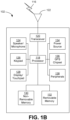
- FIG. 1B is a system diagram illustrating an example WTRU 102.
- the WTRU 102 may include a processor 118, a transceiver 120, a transmit/receive element 122, a speaker/microphone 124, a keypad 126, a display/touchpad 128, non-removable memory 130, removable memory 132, a power source 134, a global positioning system (GPS) chipset 136, and/or other peripherals 138, among others.
- GPS global positioning system
- the processor 118 may be a general purpose processor, a special purpose processor, a conventional processor, a digital signal processor (DSP), a plurality of microprocessors, one or more microprocessors in association with a DSP core, a controller, a microcontroller, Application Specific Integrated Circuits (ASICs), Field Programmable Gate Arrays (FPGAs) circuits, any other type of integrated circuit (IC), a state machine, and the like.
- the processor 118 may perform signal coding, data processing, power control, input/output processing, and/or any other functionality that enables the WTRU 102 to operate in a wireless environment.
- the processor 118 may be coupled to the transceiver 120, which may be coupled to the transmit/receive element 122. While FIG. 1B depicts the processor 118 and the transceiver 120 as separate components, it will be appreciated that the processor 118 and the transceiver 120 may be integrated together in an electronic package or chip.
- the transmit/receive element 122 may be configured to transmit signals to, or receive signals from, a base station (e.g., the base station 114a) over the air interface 116.
- a base station e.g., the base station 114a
- the transmit/receive element 122 may be an antenna configured to transmit and/or receive RF signals.
- the transmit/receive element 122 may be an emitter/detector configured to transmit and/or receive IR, UV, or visible light signals, for example.
- the transmit/receive element 122 may be configured to transmit and/or receive both RF and light signals. It will be appreciated that the transmit/receive element 122 may be configured to transmit and/or receive any combination of wireless signals.
- the transceiver 120 may be configured to modulate the signals that are to be transmitted by the transmit/receive element 122 and to demodulate the signals that are received by the transmit/receive element 122.
- the WTRU 102 may have multi-mode capabilities.
- the transceiver 120 may include multiple transceivers for enabling the WTRU 102 to communicate via multiple RATs, such as NR and IEEE 802.11, for example.
- the processor 118 of the WTRU 102 may be coupled to, and may receive user input data from, the speaker/microphone 124, the keypad 126, and/or the display/touchpad 128 (e.g., a liquid crystal display (LCD) display unit or organic light-emitting diode (OLED) display unit).
- the processor 118 may also output user data to the speaker/microphone 124, the keypad 126, and/or the display/touchpad 128.
- the processor 118 may access information from, and store data in, any type of suitable memory, such as the non-removable memory 130 and/or the removable memory 132.
- the non-removable memory 130 may include random-access memory (RAM), read-only memory (ROM), a hard disk, or any other type of memory storage device.
- the removable memory 132 may include a subscriber identity module (SIM) card, a memory stick, a secure digital (SD) memory card, and the like.
- SIM subscriber identity module
- SD secure digital
- the processor 118 may access information from, and store data in, memory that is not physically located on the WTRU 102, such as on a server or a home computer (not shown).
- the processor 118 may receive power from the power source 134, and may be configured to distribute and/or control the power to the other components in the WTRU 102.
- the power source 134 may be any suitable device for powering the WTRU 102.
- the power source 134 may include one or more dry cell batteries (e.g., nickel-cadmium (NiCd), nickel-zinc (NiZn), nickel metal hydride (NiMH), lithium-ion (Li-ion), etc.), solar cells, fuel cells, and the like.
- the processor 118 may also be coupled to the GPS chipset 136, which may be configured to provide location information (e.g., longitude and latitude) regarding the current location of the WTRU 102.
- location information e.g., longitude and latitude
- the WTRU 102 may receive location information over the air interface 116 from a base station (e.g., base stations 114a, 114b) and/or determine its location based on the timing of the signals being received from two or more nearby base stations. It will be appreciated that the WTRU 102 may acquire location information by way of any suitable location-determination method while remaining consistent with an embodiment.
- the processor 118 may further be coupled to other peripherals 138, which may include one or more software and/or hardware modules that provide additional features, functionality and/or wired or wireless connectivity.
- the peripherals 138 may include an accelerometer, an e-compass, a satellite transceiver, a digital camera (for photographs and/or video), a universal serial bus (USB) port, a vibration device, a television transceiver, a hands free headset, a Bluetooth ® module, a frequency modulated (FM) radio unit, a digital music player, a media player, a video game player module, an Internet browser, a Virtual Reality and/or Augmented Reality (VR/AR) device, an activity tracker, and the like.
- FM frequency modulated
- the peripherals 138 may include one or more sensors, the sensors may be one or more of a gyroscope, an accelerometer, a hall effect sensor, a magnetometer, an orientation sensor, a proximity sensor, a temperature sensor, a time sensor; a geolocation sensor; an altimeter, a light sensor, a touch sensor, a magnetometer, a barometer, a gesture sensor, a biometric sensor, and/or a humidity sensor.
- a gyroscope an accelerometer, a hall effect sensor, a magnetometer, an orientation sensor, a proximity sensor, a temperature sensor, a time sensor; a geolocation sensor; an altimeter, a light sensor, a touch sensor, a magnetometer, a barometer, a gesture sensor, a biometric sensor, and/or a humidity sensor.
- the WRTU 102 may include a half-duplex radio for which transmission and reception of some or all of the signals (e.g., associated with particular subframes for either the UL (e.g., for transmission) or the downlink (e.g., for reception)).
- a half-duplex radio for which transmission and reception of some or all of the signals (e.g., associated with particular subframes for either the UL (e.g., for transmission) or the downlink (e.g., for reception)).
- the WTRU is described in FIGs. 1A-1B as a wireless terminal, it is contemplated that in certain representative embodiments that such a terminal may use (e.g., temporarily or permanently) wired communication interfaces with the communication network.
- one or more, or all, of the functions described herein with regard to one or more of: WTRU 102a-d, Base Station 114a-b, eNode-B 160a-c, MME 162, SGW 164, PGW 166, gNB 180a-c, AMF 182a-b, UPF 184a-b, SMF 183a-b, DN 185a-b, and/or any other device(s) described herein, may be performed by one or more emulation devices (not shown).
- the emulation devices may be one or more devices configured to emulate one or more, or all, of the functions described herein.
- the emulation devices may be used to test other devices and/or to simulate network and/or WTRU functions.
- the one or more emulation devices may perform the one or more, including all, functions while not being implemented/deployed as part of a wired and/or wireless communication network.
- the emulation devices may be utilized in a testing scenario in a testing laboratory and/or a non-deployed (e.g., testing) wired and/or wireless communication network in order to implement testing of one or more components.
- the one or more emulation devices may be test equipment. Direct RF coupling and/or wireless communications via RF circuitry (e.g., which may include one or more antennas) may be used by the emulation devices to transmit and/or receive data.
- RF circuitry e.g., which may include one or more antennas
- FIG. 2 illustrates a block diagram of a block-based hybrid video encoding system. Note that in the present application, the terms “reconstructed” and “decoded” may be used interchangeably. Usually, but not necessarily, the term “reconstructed” is used at the encoder side while “decoded” is used at the decoder side.
- the video sequence may go through pre-processing, for example, applying a color transform to the input color picture (e.g., conversion from RGB 4:4:4 to YCbCr 4:2:0), or performing a remapping of the input picture components in order to get a signal distribution more resilient to compression (e.g., using a histogram equalization of one of the color components).
- Metadata may be associated with the pre-processing, and attached to the bitstream.
- the input video signal 102 is processed block by block.
- the HEVC specification distinguishes between “blocks” and “units,” where a "block” addresses a specific area in a sample array (e.g., luma, Y), and the “unit” includes the collocated blocks of all encoded color components (e.g., Y, Cb, Cr, or monochrome), syntax elements, and prediction data that are associated with the blocks (e.g., motion vectors).
- the term "block” can be used to refer to an array of data of various sizes, and it may be used to refer to a macroblock and a partition as specified in H.264/AVC, any of a coding tree unit (CTU), a coding unit (CU), a prediction unit (PU), a transform unit (TU), a coding block (CB), a prediction block (PB), and a transform block (TB) as in HEVC, a superblock or sub-partitioning in AV1, a CTU, CU, TU, CB, and TB as in VVC (Versatile Video Coding) or other video coding standards.
- CTU coding tree unit
- CU coding unit
- PU prediction unit
- TU transform unit
- CB coding block
- PB prediction block
- TB transform block
- HEVC extended block sizes are used to efficiently compress high resolution (1080p and beyond) video signals.
- a CU can be up to 64x64 pixels.
- a CU can be further partitioned into prediction units, for which separate prediction methods are applied. For each input video block (MB or CU), spatial prediction (160) and/or temporal prediction (162) may be performed.
- Spatial prediction uses pixels from the samples of already-coded neighboring blocks (which are called reference samples) in the same video picture/slice to predict the current video block. Spatial prediction reduces spatial redundancy inherent in the video signal.
- Temporal prediction uses reconstructed pixels from the already coded video pictures to predict the current video block. Temporal prediction reduces temporal redundancy inherent in the video signal.
- a temporal prediction signal for a given video block is usually signaled by one or more motion vectors which indicate the amount and the direction of motion between the current block and its reference block. Also, if multiple reference pictures are supported (as is the case for the recent video coding standards such as H.264/AVC or HEVC), then for each video block, its reference picture index is sent additionally; and the reference index is used to identify from which reference picture in the reference picture store (164) the temporal prediction signal comes.
- the mode decision block (180) in the encoder chooses the best prediction mode, for example based on the rate-distortion optimization method.
- the prediction block is then subtracted from the current video block (116); and the prediction residual is de-correlated using transform (104) and quantized (106).
- the encoder decodes an encoded block to provide a reference for further prediction.
- the quantized residual coefficients are inverse quantized (110) and inverse transformed (112) to form the reconstructed residual, which is then added back to the prediction block (126) to form the reconstructed video block.
- the encoder may also skip the transform and apply quantization directly to the non-transformed residual signal.
- the encoder may also bypass both transform and quantization, i.e., the residual is coded directly without the application of the transform or quantization process.
- PCM direct pulse code modulation
- coding mode inter or intra
- prediction mode information motion information
- quantized residual coefficients are all sent to the entropy coding unit (108) to be further compressed and packed to form the bitstream.
- FIG. 3 illustrates a general block diagram of a block-based video decoder (200).
- a video decoder generally performs a decoding pass reciprocal to the corresponding encoding pass, which performs video decoding as part of encoding video data.
- the video bitstream 202 is first unpacked and entropy decoded at entropy decoding unit 208.
- the coding mode and prediction information are sent to either the spatial prediction unit 260 (if intra coded) or the temporal prediction unit 262 (if inter coded) to form the prediction block.
- the residual transform coefficients are sent to inverse quantization unit 210 and inverse transform unit 212 to reconstruct the residual block.
- the prediction block and the residual block are then added together at 226.
- the reconstructed block may further go through in-loop filtering (266) before it is stored in reference picture store 264.
- the reconstructed video (220) in the reference picture store may then be stored, transmitted or used to drive a display device, as well as used to predict future video blocks.
- the decoded picture may further go through post-processing, for example, an inverse color transform (e.g., conversion from YCbCr 4:2:0 to RGB 4:4:4) or an inverse remapping performing the inverse of the remapping process performed in the pre-encoding processing.
- post-processing may use metadata derived in the pre-encoding processing and signaled in the bitstream.
- Both HEVC and the JEM adhere to the block-based motion compensated hybrid video encoding/decoding workflows as shown in FIG. 2 and FIG. 3 and are based on the same functional modules such as spatial prediction (i.e., intra prediction), temporal prediction (i.e., inter prediction), transform, quantization, entropy coding and loop filters.
- spatial prediction i.e., intra prediction
- temporal prediction i.e., inter prediction
- coding parameters used for inter prediction e.g., motion vectors (MVs), reference index, weighted prediction parameters
- R-D rate-distortion
- the overhead used to code those inter coding parameters could account for a non-negligible portion of the output bitstream.
- two template-based inter prediction techniques are applied in the JEM by deriving those inter coding parameters at the decoder based on template samples, e.g., the reconstructed neighboring samples of a current block that are previously decoded.
- the first method is called local illumination compensation (LIC).
- the LIC compensates the motion compensated prediction based on a scaling and an offset that are derived based on the template samples to address the local illumination change issue between different pictures.
- the second method is called frame-rate up conversion (FRUC) template mode, in which the motion information (MVs and reference indices) is derived at the decoder based on template matching.
- FRUC frame-rate up conversion
- LIC is a coding tool that is used in the JEM to address the issue of local illumination changes that exist in temporal neighboring pictures, as described in J. Chen, E. Alshina, G. J. Sullivan, J. R. Ohm, J. Boyce, "Algorithm description of Joint Exploration Test Model 7 (JEM7)", JVET-G1001, Jul. 2017, Torino, Italy.
- LIC is based on a linear model where a scaling factor and an offset are applied to the reference samples to obtain the prediction samples of a current block.
- FIG. 4 illustrates the LIC process. In FIG.
- a linear least mean square error (LLMSE) method is employed to derive the values of the LIC parameters ( ⁇ and ⁇ ) by minimizing the difference between the neighboring samples of the current block (the template T in FIG. 4 ) and their corresponding reference samples in the temporal reference pictures (i.e, either T0 or T1 in FIG.
- LLMSE linear least mean square error
- both the template samples and the reference template samples may be subsampled (2:1 subsampling) to derive the LIC parameters, e.g., only the shaded samples in FIG. 4 may be used to derive ⁇ and ⁇ .
- Sign prediction methods operate to perform multiple inverse transforms on the transform coefficients of a coding block. For each inverse transform, the sign of a non-zero transform coefficient is set to either negative or positive. The sign combination which minimizes a cost function is selected as the sign predictor to predict the signs of the transform coefficients of the current block. For one example to illustrate this idea, assuming the current block contains two non-zero coefficients, there are four possible sign combinations, namely, (+, +), (+, -), (-, +) and (-, -). For all four combinations, the cost function is calculated and the combination with the minimum cost is selected as a sign predictor. The cost function in this example is calculated as a discontinuity measurement of the samples sitting on the boundary between the current block and its causal neighbors.
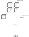
- Template-matching techniques have also been proposed for reducing the signaling of the signs for motion vector difference (MVD).
- MVD motion vector difference
- a list of MVD candidates is generated by using different combinations of the sign values for each of horizontal and vertical MVD.
- the cost of each MVD candidate is calculated using the template samples (the reconstructed neighboring samples) of the current block.
- the MVD candidates are sorted based on the calculated cost values.
- the final MVD is selected by sending an index in the sorted candidate list from the encoder to the decoder.
- A, B, C and D are four possible MVD candidates which are generated by assigning different sign values for the received absolute MVD values.
- An index is signaled to identify one of the four candidates, and the identified candidate is used to reconstruct the final MVs of the current block.
- two motion vector predictor (MVP) candidates are generated, and the candidate with the best prediction quality is selected by signaling an MVP index from encoder to decoder.
- MVP motion vector predictor
- a template-based MVP derivation method is used to avoid the MVP signaling.
- template matching is used to derive the MVP at decoder side.
- the two default MVP candidates are checked, and the candidate which leads to the smaller SAD between the template and its reference is selected as the starting point.
- a local search based on template matching around the starting point is performed and the MV which results in the minimum matching cost is selected as the MVP for the current block.
- a motion candidate reorder method is used to improve the efficiency of merge mode. Specifically, after the initial merge candidate list is generated, the original merge candidates in the list are reordered based the template-matching costs that are calculated between the template samples of the current CU and the corresponding reference samples of the template using the motion of a merge candidate. After the reordering, the merge candidates with smaller costs can be put in front of the merge candidates with larger costs. By this way, the signaling efficiency of merge candidate indices can be improved by spending fewer bits on merge candidates which provide better prediction quality.
- EMT enhanced multiple transform
- NSST non-separable secondary transform
- a transform syntax reorder has been proposed in C.-W. Hsu et al. (supra) for use in reordering the indices of multiple transforms that can be selected, for example, based on the same cost function as used for the sign prediction of transform coefficients (as described above in the section "Sign prediction of transform coefficients" using the reconstructed neighboring samples of the block.
- the possible EMT and/or NSST transform candidates are reordered based on the costs and the ones with smaller costs will be assigned with short codewords.
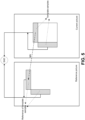
- Overlapped block motion compensation is used in the JEM reference software to remove the blocking artifacts at the motion compensation stage.
- OBMC is performed for all inter block boundaries except the right and bottom boundaries of a block.
- the OBMC is also performed for every sub-block boundary.
- FIG. 8 illustrates the concept of the OBMC. Specifically, when the OBMC is applied to a sub-block (e.g., the sub-block A in FIG.
- the MVs of four neighboring sub-blocks are also used to derive the prediction signals of the current sub-block. Then, the multiple prediction signals using the MVs of neighboring sub-blocks are averaged to generate the final prediction of the current sub-block.
- an adaptive multiple transform (AMT) tool is used for coding the residuals of both inter and intra blocks in the JEM.
- the AMT introduces four additional core transforms from the DCT/DST transform family, including DCT-VIII, DCT-V, DST-VII and DST-I.
- the AMT is applied to all the coding blocks whose width and height are no larger than 64, and a flag is signaled to indicate whether the AMT is enabled or not.
- the flag When the flag is equal to 0, it indicates that DCT-II is used as the transform for the block; otherwise (i.e., the flag is equal to 1), three transform subsets (each containing two different AMT core transforms as specified in Table 1) are defined.
- a transform subset When the AMT is applied to an intra block, a transform subset is firstly selected based on the intra prediction direction of the block. Then, two additional flags are signaled to indicate which transform (out of the two core transforms in the selected transform subset) is used as the horizontal transform and the vertical transform respectively.
- the transform subset #0 which consists of DCT-VIII and DST-VII, is used. Table 1.
- Table 1 The three transform subsets defined in the JEM. Transform subset No. Core transforms 0 DST-VII, DCT-VIII 1 DST-VII, DST-I 2 DST-VII, DCT-V
- NST mode-dependent non-separable secondary transform
- an 8x8 non-separable transform is applied to the top-left 8x8 region of the 2D transform coefficient array of the block; otherwise (i.e., either the width or the height is equal to 4 which is the minimum coding block size in the JEM), a 4x4 non-separable transform is applied to the top-left region (in the size of min(8, W) x min(8, H)) of the transform coefficients of the block.
- the 16x1 coefficient vector F ⁇ is re-organized as 4x4 block using the scanning order for that block (horizontal, vertical or diagonal).
- a hypercube-givens transform HyGT
- butterfly implementation is used to reduce the computational complexity of non-separable transform.
- the HEVC standard employs motion compensated prediction (MCP) to efficiently reduce the temporal redundancy between pictures, thus achieving high inter coding efficiency.
- MCP motion compensated prediction
- MCP only uses the samples from already-decoded pictures to predict the samples in the current picture, there is no dependency between the MCPs of spatial neighboring blocks. This means that the MCPs of the inter blocks in the same picture/slice are independent from each other.
- the decoding processes of multiple inter blocks in the current picture can be done in parallel, e.g., they can be assigned to different threads to exploit the parallelism.
- some template-based inter prediction methods e.g., template-matching based FRUC and LIC
- the template-based inter prediction methods derive those parameters at both encoder and decoder using the already-reconstructed samples of the spatial neighbors of the current block.
- its decoding process waits until the samples of its neighboring blocks (the template samples of the current block) are fully reconstructed. This can complicate the pipeline design, especially at the decoder side, therefore leading to significant complexity increase for the hardware implementation.
- FIG. 9 and FIG. 10 show examples to compare the decoding processes of HEVC and the JEM.
- four consecutive coding blocks of equal block-size in the picture are used as examples, each coding block being decoded by a separate decoding thread, and the decoding complexity of each individual decoding module (e.g., the MCP, the OBMC, the dequantization and the inverse transform) is assumed to be the same for these four coding blocks. Additionally, it is assumed that all the coding blocks in the example of the JEM are coded based on one of the template-based inter prediction techniques.
- the blocks represent the decoding process of the MCP, the OBMC, the de-quantization and the inverse transform, and the variables T MCP , T OBMC , T de-quant and T inv-trans are the decoding times of those four modules.
- the total decoding time of the HEVC is equal to the decoding time of one coding block, i.e., TMCP + Tde-quant + Tinv-trans.
- templates-based inter prediction methods are described herein for reducing the encoding/decoding latency of the template-based inter prediction methods while maintaining its main coding gain.
- some of the functions of template-based inter prediction methods remain the same as in existing designs. For example, for LIC, the parameter derivation and the linear sample adjustment processes remain the same; and for FRUC, the template-matching based motion search process remains the same.
- the generation of the template samples used by the template-based inter prediction is modified to lower the dependency between neighboring blocks such that the overall encoding/decoding latency due to the template-based inter prediction is reduced.
- changes proposed in this disclosure include those described below.
- the prediction signal i.e., the prediction samples generated from the MCP and, if applicable, OBMC
- the prediction signal i.e., the prediction samples generated from the MCP and, if applicable, OBMC
- the encoding/decoding of a template-based coding block can be invoked as soon as the prediction signal of its neighboring blocks becomes available.
- Using only a prediction signal as template may be less accurate than the fully reconstructed signal, because the reconstructed residual has not been added yet. This may result in some coding performance degradation.
- additional methods are proposed to further improve the coding performance of template-based inter prediction when the prediction signal is used as the source of template samples.
- template-based inter prediction To reduce the latency of template-based inter prediction, it is further proposed to divide a picture/slice into multiple "template slices" such that the decoding of inter blocks within a template slice can be performed independently from other template slices. To achieve such parallelism, it is proposed to disallow a coding block from using the samples that are not in the same template slice of the block as the template samples. Additionally, to reduce the potential coding loss, template slices only break the template sample dependency but still allow the other coding processes (e.g., in-loop filters, intra prediction, advanced motion vector prediction (AMVP) and so forth) to operate across template slice boundaries.
- AMVP advanced motion vector prediction
- the template-matching based FRUC and LIC are used as examples to explain the proposed methods.
- the schemes to be described are also applicable to other template-based coding schemes in which the reconstructed neighboring samples of a block are used during the encoding and/or decoding process.
- the encoding/decoding of a template-based coding block can be started right after the prediction signal of its neighboring blocks are generated without waiting for the reconstruction of the residuals of the neighboring blocks. This may lead to significant latency reduction for the template-based inter prediction methods, given that the encoding/decoding latency caused by de-quantization and inverse transform of neighboring blocks are now removed.
- FIG. 11 illustrates the parallel decoding process when a method as proposed herein is applied to the template-based inter prediction methods.
- T latency T MCP + T OBMC .
- T total 4 * ( T MCP + T OBMC ) + T de-quant + T inv-trans .
- the OBMC is applied to generate the prediction samples of an inter block whose samples are then used as the template samples for deriving the corresponding coding parameters (e.g., the FRUC MVs and the LIC parameters) for its neighboring blocks.
- the OBMC can improve the prediction quality by removing the blocking artifacts due to the multiple motion compensations that are performed, it also introduces an encoding/decoding complexity increase, therefore resulting in non-negligible encoding/decoding latency when it is combined with the template-based inter prediction methods.
- the OBMC only modifies the boundary samples of a coding block, its influence on the accuracy of the derived coding parameters is relatively low when considering its complexity increase for generating the prediction signal.
- the prediction samples of intra coded blocks can also be used as template samples for decoding the template-coded blocks.
- intra-coded blocks due to the fact that intra-coded blocks also use the reconstructed samples of their respective spatial neighbors to generate the prediction samples, such use of prediction samples may not be optimal for hardware design due to the propagated encoding/decoding latency from the neighboring intra-coded samples to the current template block.
- prediction samples of neighboring blocks that are coded in intra modes are disabled for use as template samples of the current block. Specifically, in such embodiments, if a template sample is from an intra-coded neighboring block, it is treated as unavailable for the current block.
- prediction samples (generated either after or before the OBMC is applied) are used to replace reconstructed samples as the template samples for the template-based inter prediction methods.
- the methods can significantly reduce the encoding/decoding latency, the differences between the prediction samples and the reconstructed samples (the reconstructed residual signal) could cause the coding parameters that are derived for the template-based inter prediction (e.g., motion vectors for FRUC or weight/offset parameters for LIC) to become less accurate, therefore leading to negative impacts on the overall coding performance. Additional methods are further proposed herein to compensate for the possible coding performance drop when the prediction signal is employed in the template-based inter prediction.
- Template-based inter prediction by adaptively enabling prediction samples based on the existence of non-zero residuals.
- Embodiments in which a prediction signal is used in template-based prediction can maintain much of the coding gain of template-based inter prediction, especially in cases where the reconstruction signal and the prediction signal are very similar.
- the use of the prediction signal may be less satisfactory when there are large prediction errors (i.e., non-zero residuals with large magnitudes) for the neighboring template samples.
- the neighboring template samples are coded with zero residuals, it is still reliable to use them as the template samples for the current block given that they are the same as the reconstructed samples.
- the decision on whether a prediction sample has a non-zero residual or not is made based on the coded block flag (CBF) that is signaled in the bitstream, which indicates if a block contains non-zero transform coefficients or not.
- CBF coded block flag
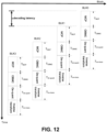
- FIG. 13 shows one example to illustrate such a method.
- the neighboring sample positions labeled as A 0 and A 1 and the neighboring sample positions labeled as L 0 to L 3 belong to an above neighboring block Blk0 and a left neighboring block Blk2, respectively, both having the CBF equal to 0. Since there is only zero residual for these two neighboring blocks, prediction samples at those positions labeled A 0 and A 1 and L 0 through L 3 can be used as the template samples in the template-based methods (e.g. FRUC and/or LIC).
- the template-based methods e.g. FRUC and/or LIC.
- the corresponding prediction samples may not be used as template samples in some embodiments; this is because they are different from the reconstructed sample values and therefore may be considered as less accurate.
- the decision on whether residuals are all zero or not is made for each neighboring sample, and the decisions on the samples in the same template may be different from each other.
- sample-based differentiation may be unfriendly to practical hardware implementations, e.g., special attention may be needed for the FRUC SAD calculation and the LIC parameter derivation process where the samples in a template are treated differently based on whether they have residuals or not.
- the samples in a template sub-region that is either above or left to the current block.
- it allows the samples in a template sub-region (either the left template sub-region or the above template sub-region) of a block to be used as template samples only if all residuals associated with all the samples in that template sub-region are zero.
- the left template sub-region i.e., L 0 to L 3
- the left template sub-region is enabled for the template-based inter prediction.
- the neighboring block that contains the samples A 2 and A 3 has residuals, the whole above template sub-region (i.e., A 0 to A 3 ) is not used as template samples.
- the prediction samples that have small residuals play a more important role than the prediction samples that have large residuals to achieve an accurate estimation of the coding parameters for the template-based inter prediction.
- the prediction samples A 0 and Ai, and L 0 to L 3 do not have residuals, they are considered to be more reliable. When using these samples to estimate the template parameters, larger weight may be assigned to those samples. Conversely, because the prediction samples A 2 and A 3 have non-zero residuals, those samples will be given a smaller weight when being used as template samples. The weighted prediction samples will be used as the input for the estimation of the template parameters.
- T ( x i , y i ) is the template sample at the coordinate ( x i , y i )
- T r ( x i + v x , y i + v y ) is the corresponding reference sample of the template sample based on the motion vector ( v x , v y ) in the reference picture
- w i is the weight that is assigned to T ( x i , y i ) .
- the magnitude ratio that is used in equation (10) may be calculated in the transform domain without applying the de-quantization and the inverse transform.
- Template-based inter prediction based on adding a DC offset to prediction samples.
- 2D transform and 2D inverse transform are also used in the JEM to achieve a good energy compaction on the prediction residual.
- the majority of signal energy in a coding block is concentrated into a few low-frequency coefficients.
- the error between the original signal and the prediction signal of the block i.e., the residuals of the block
- the 2D transform may even compact the energy of the residuals into one single coefficient (e.g., the DC coefficient for the conventional DCT-II transform that is used in HEVC and previous standards) in the transform domain.
- the accuracy of the derived template parameters is dependent on the similarity between the prediction signal and the reconstructed signal of the template samples. Examining closely how the FRUC motion search is performed and how LIC parameter derivation is performed, one finds that the template sample values are often evaluated in a collective manner (either in the form of SAD or following equations (2) and (3)). This means that the high frequency components in the template signal may be much less important than the low frequency components of the template. In some embodiments, it is proposed to correct the prediction signal by adding just the DC component onto the prediction samples before they are used as template samples for the template-based inter prediction methods. Doing this will correct the most important frequency of the template samples (i.e. the DC component) without incurring latency, because the reconstruction of the DC component is relatively easy and does not require inverse transform.
- Equation (12) is a floating-point operation.
- M Bsize and L BSize are introduced to compensate the 0.5-bit right shift when the dynamic range increase due to the size of 2D transform cannot be purely implemented by right shifts.
- the quantization step size increases approximately 2 1/6 times with each increment of QP and approximately increase 2 0.5 for every 3 increments of QP. Therefore, in another embodiment, instead of scaling-based method (as in equation (14)), it is proposed to decrease the QP value by 3 to approximate the 0.5-bit right shift when the dynamic range increase of the 2D transform is not exactly equal to the power of 2.
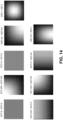
- FIG. 14 illustrates the lowest frequency responses of the primary transform functions that are used in the current JEM, where each sub-figure corresponds to a pair of a horizontal transform and a vertical transform. As shown in FIG. 14 , except for the transforms DCT-II + DCT II and DCT-V + DCT-V, the lowest frequency responses of the other core transform basis functions are far away from being accurate for approximating the real DC value.
- the prediction signal when a block is coded by using the primary transform of either DCT-II or DCT-V; for the blocks that use the other primary transform functions, the prediction signal will be directly used as the template samples without adding the offset.
- the DC offset e.g., the offset as calculated in equation (12)
- Template-based inter prediction based on adaptive template size
- a fixed template size e.g., four rows/columns of neighboring samples for the FRUC template-matching mode and one row/column of neighboring samples for LIC.
- a design may not be optimal due to the correlation between the samples of a coding block and its template samples being dependent on the selected template size. For example, choosing a large template size has the drawback that the samples of the template tend to be far away from the target block. Therefore, the correlation between the current block and its template may be insufficient.
- large template size may also be advantageous in the sense that it can yield a more reliable estimation in the presence of noise (e.g., the video capture noise and the noise caused by the coding process).
- Some embodiments operate to select an appropriate template size for different block sizes, which should be large enough against noise while not exceeding the size limit to ensure a sufficient correlation between the template and the target block.
- analysis may be done at encoder to determine the noise that is contained in the original video as well as the coding noise that the encoding process may introduce (e.g. based on the QP value). If the noise level is high, then a large template size may be selected to counteract the noise; otherwise (i.e., the noise level is small), a small template size may be selected to ensure the samples of the current block and the template are sufficiently correlated.
- one cause of encoding/decoding latency for template-based inter prediction methods is the dependency between the MCP of a template-based coding block and the reconstruction of its neighboring samples. Additionally, as shown in FIG. 10 , the worst-case encoding/decoding latency introduced by the template-based prediction directly relates to the maximum number of consecutive blocks that are coded by the template-based inter prediction methods.
- template slices are used to limit the maximum encoding/decoding latency of the template-based inter prediction techniques. Specifically, with the use of template slices, a picture/slice is divided into multiple separate segments (or template slices) and the decoded samples of each block in a segment are only allowed to be used as the template samples for the template-based coding of other blocks in the same segment, but not allowed to be used as template samples for template-based coding of the blocks in any of the other segments. In this way, the encoding/decoding of the blocks in each template slice can be completely independent from the other template slices.
- syntax elements may be added at the sequence and/or picture level.
- the number of CTUs in each template slice may be signaled in the Sequence Parameter Set (SPS) and/or the Picture Parameter Set (PPS), or may be signaled in the slice header.
- SPS Sequence Parameter Set
- PPS Picture Parameter Set
- Other variations of syntax elements may be used, for example, the number of CTU rows may be used, or the number of template slices in each picture may be used, etc.
- a flag may be signaled to indicate at the sequence or picture level if template slices are used.
- the number of the CTUs or CTU rows of each template slice may be different from each other.
- a syntax element may be firstly signaled in the SPS, PPS and/or slice to indicate the number of template slices in the current sequence, picture or slice, followed by a set of other syntax elements which specify the corresponding number of CTUs or CTU rows in each template slice respectively.
- the boundary of each template slice is always aligned with CTU boundaries (such that the size of a template slice is a multiple of the CTU size).
- the FRUC template-matching and LIC are used as examples to illustrate the proposed template-based methods, such as the methods described in the sections "Template-based inter prediction based on prediction signal" and "Template-based inter prediction based on template slice,” above.
- the proposed methods are applied to other template-based coding schemes.
- the proposed methods as discussed above can be adapted to other template-based coding methods where the reconstructed neighboring samples are used for the encoding/decoding of the current block, including template-based coding methods such as transform coefficient sign prediction, motion vector difference sign derivation, template-based motion vector prediction, merge candidate reorder, and transform syntax reorder.
- the prediction samples instead of the reconstructed neighboring samples, the prediction samples (with or without adding the DC component) are used to calculate the cost functions that are used to select the sign values (e.g., the transform coefficient sign prediction and the motion vector difference sign derivation) and the motion vectors (e.g., template-based motion prediction and merge candidate reorder).
- the sign values e.g., the transform coefficient sign prediction and the motion vector difference sign derivation
- the motion vectors e.g., template-based motion prediction and merge candidate reorder
- Pred is the prediction signal of the neighboring samples
- P is prediction of the current block
- r is the residual hypothesis.
- a version of the prediction signal can be generated for a neighboring block using one or more prediction techniques.
- This initial version may be further adjusted based on one or more other prediction techniques to refine the prediction signal, which can be added to the prediction residual for the neighboring block to reconstruct the neighboring block.
- the prediction signal of the neighboring block (the initial version or the adjusted one) can be used to form the template when applying template-based inter prediction to the current block.
- prediction processes MCP, OBMC
- MCP prediction residual generation processes
- the prediction processes can be implemented independently of the prediction residual generation processes, and the prediction block and the residual block may be obtained in different orders than what is described before. It should be noted that the present techniques of using neighboring prediction samples for template-based inter prediction of the current block would still be applicable when the residual block is generated in a different order.
- FIG. 16 illustrates an example method 1600 for encoding a block using template-based inter prediction, according to an embodiment.
- Method 1600 starts at an initialization step 1605.
- an encoder may access the prediction samples of neighboring blocks that can be used to form a template and the CBFs of the neighboring blocks.
- the template for the current block is formed based on prediction samples of neighboring blocks.
- the template may be formed by neighboring samples from top and left adjacent blocks, or the template may be formed by further using the information indicating whether the neighboring samples correspond to zero or non-zero residuals.
- the size of template may also be adapted to the block size or the noise level.
- the prediction samples used for the template may be obtained after performing part or all of the inter prediction processes.
- the corresponding template in the reference picture is then formed using the reconstructed samples.
- step 1620 FRUC is performed to obtain the motion vector.
- step 1630 the weight and offset are obtained for LIC.
- the parameters obtained from steps 1620 and 1630 may be used to generate the prediction for the current block at step 1640.
- Other prediction techniques such as OBMC, can also be used in generating the prediction.
- the prediction residuals for the current block can be generated by subtracting the prediction block from the original block. The prediction residuals can then be quantized, transformed and entropy coded.
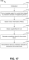
- FIG. 17 illustrates an example method 1700 for decoding a block using template-based inter prediction, according to an embodiment.
- Method 1700 starts at an initialization step 1705.
- a decoder may access the prediction samples of neighboring blocks that can be used to form a template, the CBFs of the neighboring blocks, and the quantized transform coefficients for the current block.
- the template for the current block is formed based on prediction samples of neighboring blocks.
- the template at the decoder side should be formed in the same manner as the encoder side.
- the corresponding template in the reference picture is then formed using the reconstructed samples.
- template-based inter prediction is then performed.
- FRUC is performed to obtain the motion vector.
- the weight and offset are obtained for LIC.
- the parameters obtained from steps 1720 and 1730 may be used to generate the prediction for the current block at step 1740.
- Other inter prediction techniques such as OBMC, can also be used in generating the prediction.
- the current block can be decoded by adding the prediction block to the prediction residuals of the current block.
- FRUC and LIC are used for generating the prediction block.
- Other template-based coding techniques may also be performed in order to contribute to the prediction (and/or reconstruction) of the current block. It should be noted that the encoding or decoding method may proceed with only FRUC (no LIC), with only LIC (no FRUC), with both FRUC and LIC, or more generally with any feasible combination of the template-based coding methods as described before.
- modules for example, the inter prediction, and/or transform modules (162, 104, 112, 262, 212), of a video encoder 100 and decoder 200 as shown in FIG. 2 and FIG. 3 .
- present aspects are not limited to VVC or HEVC, and can be applied, for example, to other standards and recommendations, and extensions of any such standards and recommendations.
- numeric values are used in the present application, for example, the block size used to determine the template size
- the specific values are provided for example purposes and the aspects described are not limited to these specific values.
- Decoding can encompass all or part of the processes performed, for example, on a received encoded sequence in order to produce a final output suitable for display.
- processes include one or more of the processes typically performed by a decoder, for example, entropy decoding, inverse quantization, inverse transformation, and differential decoding.
- a decoder for example, entropy decoding, inverse quantization, inverse transformation, and differential decoding.
- encoding can encompass all or part of the processes performed, for example, on an input video sequence in order to produce an encoded bitstream.
- processes include one or more of the processes typically performed by an encoder, for example, partitioning, differential encoding, transformation, quantization, and entropy encoding.
- non-transitory computer-readable storage media include, but are not limited to, a read only memory (ROM), random access memory (RAM), a register, cache memory, semiconductor memory devices, magnetic media such as internal hard disks and removable disks, magneto-optical media, and optical media such as CD-ROM disks, and digital versatile disks (DVDs).
- ROM read only memory
- RAM random access memory
- a processor in association with software may be used to implement a video encoder, a video decoder or both, a radio frequency transceiver for use in a UE, WTRU, terminal, base station, RNC, or any host computer.
- processing platforms, computing systems, controllers, and other devices containing processors are noted. These devices may contain at least one Central Processing Unit (“CPU”) and memory.
- CPU Central Processing Unit
- FIG. 1 A block diagram illustrating an exemplary computing system
- FIG. 1 A block diagram illustrating an exemplary computing system
- FIG. 1 A block diagram illustrating an exemplary computing system
- FIG. 1 A block diagram illustrating an exemplary computing system
- FIG. 1 A block diagram illustrating an exemplary computing system
- memory may contain at least one Central Processing Unit ("CPU") and memory.
- CPU Central Processing Unit
- Such acts and operations or instructions may be referred to as being "executed,” “computer executed” or "CPU executed”.
- an electrical system represents data bits that can cause a resulting transformation or reduction of the electrical signals and the maintenance of data bits at memory locations in a memory system to thereby reconfigure or otherwise alter the CPU's operation, as well as other processing of signals.
- the memory locations where data bits are maintained are physical locations that have particular electrical, magnetic, or optical properties corresponding to or representative of the data bits. It should be understood that the exemplary embodiments are not limited to the above-mentioned platforms or CPUs and that other platforms and CPUs may support the provided methods.
- the data bits may also be maintained on a computer readable medium including magnetic disks, optical disks, and any other volatile (e.g., Random Access Memory (“RAM”)) or non-volatile (e.g., Read-Only Memory (“ROM”)) mass storage system readable by the CPU.
- RAM Random Access Memory
- ROM Read-Only Memory
- the computer readable medium may include cooperating or interconnected computer readable medium, which exist exclusively on the processing system or are distributed among multiple interconnected processing systems that may be local or remote to the processing system. It is understood that the representative embodiments are not limited to the above-mentioned memories and that other platforms and memories may support the described methods.
- any of the operations, processes, etc. described herein may be implemented as computer-readable instructions stored on a computer-readable medium.
- the computer-readable instructions may be executed by a processor of a mobile unit, a network element, and/or any other computing device.
- Suitable processors include, by way of example, a general purpose processor, a special purpose processor, a conventional processor, a digital signal processor (DSP), a plurality of microprocessors, one or more microprocessors in association with a DSP core, a controller, a microcontroller, Application Specific Integrated Circuits (ASICs), Application Specific Standard Products (ASSPs), Field Programmable Gate Arrays (FPGAs) circuits, any other type of integrated circuit (IC), and/or a state machine.
- DSP digital signal processor
- ASICs Application Specific Integrated Circuits
- ASSPs Application Specific Standard Products
- FPGAs Field Programmable Gate Arrays
- ASICs Application Specific Integrated Circuits
- FPGAs Field Programmable Gate Arrays
- DSPs digital signal processors
- ASICs Application Specific Integrated Circuits
- FPGAs Field Programmable Gate Arrays
- DSPs digital signal processors
- FIG. 1 ASICs
- FIG. 1 ASICs
- FIG. 1 ASICs
- FIG. 1 ASICs
- FIG. 1 ASICs
- FIG. 1 ASICs
- FIG. 1 Application Specific Integrated Circuits
- FPGAs Field Programmable Gate Arrays
- DSPs digital signal processors
- a signal bearing medium examples include, but are not limited to, the following: a recordable type medium such as a floppy disk, a hard disk drive, a CD, a DVD, a digital tape, a computer memory, etc., and a transmission type medium such as a digital and/or an analog communication medium (e.g., a fiber optic cable, a waveguide, a wired communications link, a wireless communication link, etc.).
- a signal bearing medium include, but are not limited to, the following: a recordable type medium such as a floppy disk, a hard disk drive, a CD, a DVD, a digital tape, a computer memory, etc.
- a transmission type medium such as a digital and/or an analog communication medium (e.g., a fiber optic cable, a waveguide, a wired communications link, a wireless communication link, etc.).
- any two components so associated may also be viewed as being “operably connected”, or “operably coupled”, to each other to achieve the desired functionality, and any two components capable of being so associated may also be viewed as being “operably couplable” to each other to achieve the desired functionality.
- operably couplable include but are not limited to physically mateable and/or physically interacting components and/or wirelessly interactable and/or wirelessly interacting components and/or logically interacting and/or logically interactable components.
- the phrase “A or B” will be understood to include the possibilities of “A” or “B” or “A and B.”
- the terms “any of” followed by a listing of a plurality of items and/or a plurality of categories of items, as used herein, are intended to include “any of,” “any combination of,” “any multiple of,” and/or “any combination of multiples of” the items and/or the categories of items, individually or in conjunction with other items and/or other categories of items.
- the term “set” or “group” is intended to include any number of items, including zero.
- the term “number” is intended to include any number, including zero.
- a range includes each individual member.
- a group having 1-3 cells refers to groups having 1, 2, or 3 cells.
- a group having 1-5 cells refers to groups having 1, 2, 3, 4, or 5 cells, and so forth.
- the systems may be implemented in software on microprocessors/general purpose computers (not shown).
- one or more of the functions of the various components may be implemented in software that controls a general-purpose computer.
Landscapes
- Engineering & Computer Science (AREA)
- Multimedia (AREA)
- Signal Processing (AREA)
- Physics & Mathematics (AREA)
- Discrete Mathematics (AREA)
- General Physics & Mathematics (AREA)
- Computing Systems (AREA)
- Theoretical Computer Science (AREA)
- Compression Or Coding Systems Of Tv Signals (AREA)
- Compression, Expansion, Code Conversion, And Decoders (AREA)
Applications Claiming Priority (3)
| Application Number | Priority Date | Filing Date | Title |
|---|---|---|---|
| US201862650956P | 2018-03-30 | 2018-03-30 | |
| US201862656247P | 2018-04-11 | 2018-04-11 | |
| PCT/US2019/023557 WO2019190907A1 (en) | 2018-03-30 | 2019-03-22 | Template-based inter prediction techniques based on encoding and decoding latency reduction |
Publications (2)
| Publication Number | Publication Date |
|---|---|
| EP3777167A1 EP3777167A1 (en) | 2021-02-17 |
| EP3777167B1 true EP3777167B1 (en) | 2025-01-15 |
Family
ID=66041754
Family Applications (1)
| Application Number | Title | Priority Date | Filing Date |
|---|---|---|---|
| EP19715730.8A Active EP3777167B1 (en) | 2018-03-30 | 2019-03-22 | Template-based inter prediction techniques based on encoding and decoding latency reduction |
Country Status (6)
| Country | Link |
|---|---|
| US (2) | US11317085B2 (https=) |
| EP (1) | EP3777167B1 (https=) |
| JP (1) | JP7337072B2 (https=) |
| CN (1) | CN112106367B (https=) |
| TW (1) | TWI799554B (https=) |
| WO (1) | WO2019190907A1 (https=) |
Families Citing this family (46)
| Publication number | Priority date | Publication date | Assignee | Title |
|---|---|---|---|---|
| JP7334730B2 (ja) * | 2018-03-30 | 2023-08-29 | ソニーグループ株式会社 | 画像処理装置および方法 |
| KR20210006355A (ko) * | 2018-05-07 | 2021-01-18 | 인터디지털 브이씨 홀딩스 인코포레이티드 | 인코딩/디코딩에서의 데이터 의존성 |
| JP7666928B2 (ja) * | 2018-05-28 | 2025-04-22 | インターデジタル ヴイシー ホールディングス, インコーポレイテッド | 符号化/復号化におけるデータ依存関係 |
| EP3868098B1 (en) * | 2019-01-18 | 2024-07-10 | Huawei Technologies Co., Ltd. | Method and apparatus of local illumination compensation for predictive coding |
| US11533491B2 (en) * | 2019-08-28 | 2022-12-20 | Qualcomm Incorporated | Picture and sub-picture boundary processing for combined bilateral filter and Hadamard transform domain filter as in-loop filters |
| US11412264B2 (en) * | 2019-09-24 | 2022-08-09 | Qualcomm Incorporated | Parameter set signaling for video coding |
| MX2022003998A (es) * | 2019-10-04 | 2022-04-26 | Lg Electronics Inc | Metodo de codificacion de imagenes a base de transformacion, y aparato para el mismo. |
| WO2021130374A1 (en) * | 2019-12-27 | 2021-07-01 | Interdigital Vc Holdings France | Transform coding for inter-predicted video data |
| WO2021173552A1 (en) | 2020-02-24 | 2021-09-02 | Bytedance Inc. | Interaction between subpicture and tile row signaling |
| EP4097980A4 (en) | 2020-03-03 | 2023-04-19 | ByteDance Inc. | NON-SEPARABLE LOW-FREQUENCY TRANSFORMATION SIGNALING IN VIDEO ENCODING |
| US12177475B2 (en) * | 2021-01-29 | 2024-12-24 | Qualcomm Incorporated | Model-based motion vector difference derivation and template matching prediction for video coding |
| US12519930B2 (en) | 2021-04-09 | 2026-01-06 | Beijing Bytedance Network Technology Co., Ltd. | Adaptive motion candidate list |
| US12432339B2 (en) * | 2021-06-29 | 2025-09-30 | Qualcomm Incorporated | Merge candidate reordering in video coding |
| WO2023020446A1 (en) * | 2021-08-16 | 2023-02-23 | Mediatek Inc. | Candidate reordering and motion vector refinement for geometric partitioning mode |
| WO2023020444A1 (en) * | 2021-08-16 | 2023-02-23 | Mediatek Inc. | Candidate reordering for merge mode with motion vector difference |
| WO2023020389A1 (en) * | 2021-08-19 | 2023-02-23 | Mediatek Singapore Pte. Ltd. | Method and apparatus for low-latency template matching in video coding system |
| WO2023049292A1 (en) * | 2021-09-22 | 2023-03-30 | Beijing Dajia Internet Information Technology Co., Ltd. | Methods and devices for decoder-side intra mode derivation |
| WO2023046955A1 (en) * | 2021-09-27 | 2023-03-30 | Interdigital Vc Holdings France, Sas | Template-based syntax element prediction |
| US20230094825A1 (en) * | 2021-09-28 | 2023-03-30 | Qualcomm Incorporated | Motion vector difference sign prediction for video coding |
| EP4412199A4 (en) * | 2021-10-01 | 2025-10-08 | Lg Electronics Inc | INTRA-PREDICTION METHOD AND DEVICE BASED ON INTRA-PREDICTION MODE DERIVATION |
| US12375644B2 (en) * | 2021-10-05 | 2025-07-29 | Tencent America LLC | Grouping based adaptive reordering of merge candidate |
| WO2023072216A1 (en) * | 2021-10-28 | 2023-05-04 | Beijing Bytedance Network Technology Co., Ltd. | Method, apparatus, and medium for video processing |
| US20230140628A1 (en) * | 2021-11-04 | 2023-05-04 | Meta Platforms, Inc. | Novel buffer format for a two-stage video encoding process |
| CN114154446B (zh) * | 2021-11-15 | 2025-02-11 | 南京航空航天大学 | 基于混合时间尺度建模的直流电力系统动态特性分析方法 |
| US12034932B2 (en) | 2021-11-22 | 2024-07-09 | Tencent America LLC | Constrained template matching |
| WO2023131125A1 (en) * | 2022-01-04 | 2023-07-13 | Beijing Bytedance Network Technology Co., Ltd. | Method, apparatus, and medium for video processing |
| US20230328227A1 (en) * | 2022-04-07 | 2023-10-12 | Tencent America LLC | Systems and methods for joint coding of motion vector difference using template matching based scaling factor derivation |
| US20250254322A1 (en) * | 2022-04-08 | 2025-08-07 | Interdigital Ce Patent Holdings, Sas | Latency constrained template-based operations |
| WO2023195824A1 (ko) * | 2022-04-08 | 2023-10-12 | 한국전자통신연구원 | 영상 부호화/복호화를 위한 방법, 장치 및 기록 매체 |
| WO2023197193A1 (zh) * | 2022-04-12 | 2023-10-19 | Oppo广东移动通信有限公司 | 编解码方法、装置、编码设备、解码设备以及存储介质 |
| WO2023202569A1 (en) * | 2022-04-19 | 2023-10-26 | Mediatek Inc. | Extended template matching for video coding |
| CN119586139A (zh) * | 2022-07-12 | 2025-03-07 | 抖音视界有限公司 | 用于视频处理的方法、装置和介质 |
| US12356004B2 (en) * | 2022-07-13 | 2025-07-08 | Tencent America LLC | Intra block copy (IBC) candidate list construction with motion information of intra template-matching prediction |
| US12506883B2 (en) | 2022-07-13 | 2025-12-23 | Tencent America LLC | Template matching for multiple reference line intra prediction |
| EP4584953A1 (en) * | 2022-09-07 | 2025-07-16 | InterDigital CE Patent Holdings, SAS | Encoding and decoding methods using template-based tool and corresponding apparatuses |
| JP2024047921A (ja) * | 2022-09-27 | 2024-04-08 | シャープ株式会社 | 画像復号装置 |
| CN120569971A (zh) * | 2022-12-01 | 2025-08-29 | 现代自动车株式会社 | 使用基于模板匹配的帧间预测的视频编码方法及设备 |
| CN120303926A (zh) * | 2022-12-06 | 2025-07-11 | 现代自动车株式会社 | 针对位移符号预测使用模板调整的视频编码方法和设备 |
| EP4655946A2 (en) * | 2023-01-27 | 2025-12-03 | Guangdong Oppo Mobile Telecommunications Corp., Ltd. | Systems and methods for intra template matching prediction with improved search areas |
| US12238317B2 (en) * | 2023-03-13 | 2025-02-25 | Tencent America LLC | Block based weighting factor for joint motion vector difference coding mode |
| WO2024207136A1 (zh) * | 2023-04-03 | 2024-10-10 | Oppo广东移动通信有限公司 | 编解码方法、码流、编码器、解码器以及存储介质 |
| WO2024219876A1 (ko) * | 2023-04-19 | 2024-10-24 | 엘지전자 주식회사 | 인트라 예측에 기반한 영상 부호화/복호화 방법, 장치 및 비트스트림을 저장하는 기록 매체 |
| WO2024232516A1 (ko) * | 2023-05-10 | 2024-11-14 | 현대자동차주식회사 | 템플릿 매칭 예측을 위한 적응적 탐색 영역 결정을 위한 방법 |
| US20250024044A1 (en) * | 2023-07-11 | 2025-01-16 | Tencent America LLC | On derivation and propagation of coded information of inter prediction |
| US12604008B2 (en) * | 2023-11-22 | 2026-04-14 | Tencent America LLC | Adaptive clipping in models parameters derivations methods for video compression |
| US20260012602A1 (en) * | 2024-07-05 | 2026-01-08 | Sharp Kabushiki Kaisha | Systems and methods for performing local illumination compensation for screen captured content in video coding |
Family Cites Families (31)
| Publication number | Priority date | Publication date | Assignee | Title |
|---|---|---|---|---|
| CN101557514B (zh) * | 2008-04-11 | 2011-02-09 | 华为技术有限公司 | 一种帧间预测编解码方法、装置及系统 |
| CN101686393B (zh) * | 2008-09-28 | 2012-10-17 | 华为技术有限公司 | 应用于模板匹配的快速运动搜索方法及装置 |
| TW201032600A (en) * | 2009-02-20 | 2010-09-01 | Sony Corp | Image processing device and method |
| JP2010268259A (ja) * | 2009-05-15 | 2010-11-25 | Sony Corp | 画像処理装置および方法、並びにプログラム |
| EP2640075A3 (en) * | 2009-12-08 | 2014-02-26 | Thomson Licensing | Methods and apparatus for adaptive template matching prediction for video encoding and decoding |
| RU2487489C2 (ru) | 2011-10-18 | 2013-07-10 | Федеральное государственное автономное образовательное учреждение высшего профессионального образования "Национальный исследовательский университет "МИЭТ" | Способ поиска векторов перемещений в динамических изображениях |
| BR112014032182A2 (pt) * | 2012-07-02 | 2017-06-27 | Panasonic Ip Corp America | método de decodificação de imagem, método de codificação de imagem, aparelho de decodificação de imagem, aparelho de codificação de imagem, e aparelho de codificação e decodificação de imagem |
| WO2015103496A2 (en) * | 2014-01-02 | 2015-07-09 | Vid Scale, Inc. | Two-demensional palette coding for screen content coding |
| KR102319384B1 (ko) * | 2014-03-31 | 2021-10-29 | 인텔렉추얼디스커버리 주식회사 | 템플릿 매칭 기반의 화면 내 픽쳐 부호화 및 복호화 방법 및 장치 |
| WO2016019207A1 (en) | 2014-08-01 | 2016-02-04 | Boston Scientific Scimed, Inc. | Pressure sensing guidewires |
| CN104363449B (zh) * | 2014-10-31 | 2017-10-10 | 华为技术有限公司 | 图像预测方法及相关装置 |
| CN108028942B (zh) * | 2015-06-04 | 2020-06-26 | 清华大学 | 像素预测方法、编码方法、解码方法及其装置、存储介质 |
| CN108293131B (zh) | 2015-11-20 | 2021-08-31 | 联发科技股份有限公司 | 基于优先级运动矢量预测子推导的方法及装置 |
| US10148696B2 (en) * | 2015-12-18 | 2018-12-04 | Nicira, Inc. | Service rule console for creating, viewing and updating template based service rules |
| US10341297B2 (en) * | 2015-12-18 | 2019-07-02 | Nicira, Inc. | Datapath processing of service rules with qualifiers defined in terms of template identifiers and/or template matching criteria |
| WO2017184970A1 (en) * | 2016-04-22 | 2017-10-26 | Vid Scale, Inc. | Prediction systems and methods for video coding based on filtering nearest neighboring pixels |
| US11363253B2 (en) * | 2016-05-13 | 2022-06-14 | Vid Scale, Inc. | Systems and methods for generalized multi-hypothesis prediction for video coding |
| WO2018021585A1 (ko) * | 2016-07-26 | 2018-02-01 | 엘지전자 주식회사 | 영상 코딩 시스템에서 인트라 예측 방법 및 장치 |
| US10390015B2 (en) | 2016-08-26 | 2019-08-20 | Qualcomm Incorporated | Unification of parameters derivation procedures for local illumination compensation and cross-component linear model prediction |
| WO2018049594A1 (en) * | 2016-09-14 | 2018-03-22 | Mediatek Inc. | Methods of encoder decision for quad-tree plus binary tree structure |
| US10880552B2 (en) * | 2016-09-28 | 2020-12-29 | Lg Electronics Inc. | Method and apparatus for performing optimal prediction based on weight index |
| US10951912B2 (en) * | 2016-10-05 | 2021-03-16 | Qualcomm Incorporated | Systems and methods for adaptive selection of weights for video coding |
| US10750203B2 (en) * | 2016-12-22 | 2020-08-18 | Mediatek Inc. | Method and apparatus of adaptive bi-prediction for video coding |
| WO2018113658A1 (en) * | 2016-12-22 | 2018-06-28 | Mediatek Inc. | Method and apparatus of motion refinement for video coding |
| US10931969B2 (en) * | 2017-01-04 | 2021-02-23 | Qualcomm Incorporated | Motion vector reconstructions for bi-directional optical flow (BIO) |
| US10701366B2 (en) * | 2017-02-21 | 2020-06-30 | Qualcomm Incorporated | Deriving motion vector information at a video decoder |
| US20200154124A1 (en) * | 2017-07-04 | 2020-05-14 | Lg Electronics Inc. | Image decoding method based on inter prediction and image decoding apparatus therefor |
| US10757442B2 (en) | 2017-07-05 | 2020-08-25 | Qualcomm Incorporated | Partial reconstruction based template matching for motion vector derivation |
| MX2020007355A (es) * | 2018-01-16 | 2020-10-12 | Vid Scale Inc | Bipredicción compensada en movimiento basada en compensación de iluminación local. |
| CN118741140A (zh) * | 2018-01-24 | 2024-10-01 | 交互数字Vc控股公司 | 用于具有降低的译码复杂性的视频译码的广义双预测 |
| US10511852B1 (en) * | 2018-07-13 | 2019-12-17 | Tencent America LLC | Method and apparatus for video coding |
-
2019
- 2019-03-22 JP JP2020537004A patent/JP7337072B2/ja active Active
- 2019-03-22 CN CN201980015288.0A patent/CN112106367B/zh active Active
- 2019-03-22 US US16/969,190 patent/US11317085B2/en active Active
- 2019-03-22 EP EP19715730.8A patent/EP3777167B1/en active Active
- 2019-03-22 WO PCT/US2019/023557 patent/WO2019190907A1/en not_active Ceased
- 2019-03-26 TW TW108110420A patent/TWI799554B/zh active
-
2022
- 2022-03-14 US US17/694,168 patent/US11991351B2/en active Active
Also Published As
| Publication number | Publication date |
|---|---|
| CN112106367A (zh) | 2020-12-18 |
| JP7337072B2 (ja) | 2023-09-01 |
| US11317085B2 (en) | 2022-04-26 |
| US20200374513A1 (en) | 2020-11-26 |
| RU2020128729A (ru) | 2022-05-04 |
| EP3777167A1 (en) | 2021-02-17 |
| WO2019190907A1 (en) | 2019-10-03 |
| US20220201290A1 (en) | 2022-06-23 |
| TW201943276A (zh) | 2019-11-01 |
| CN112106367B (zh) | 2023-05-30 |
| US11991351B2 (en) | 2024-05-21 |
| TWI799554B (zh) | 2023-04-21 |
| JP2021518059A (ja) | 2021-07-29 |
Similar Documents
| Publication | Publication Date | Title |
|---|---|---|
| US11991351B2 (en) | Template-based inter prediction techniques based on encoding and decoding latency reduction | |
| US12395674B2 (en) | Methods and apparatus for reducing the coding latency of decoder-side motion refinement | |
| KR102824581B1 (ko) | 광류를 사용한 인터 예측 개선을 위한 시스템, 장치 및 방법 | |
| US20260039801A1 (en) | Complexity reduction and bit-width control for bi-directional optical flow | |
| KR20210142610A (ko) | Affine 모션 모델 유도 방법 | |
| US20250168350A1 (en) | Methods and systems for post-reconstruction filtering | |
| JP2022536967A (ja) | オプティカルフローによる動き補償のための精度精緻化 | |
| US12464150B2 (en) | Methods and apparatus for performing real-time VVC decoding | |
| RU2789522C2 (ru) | Методики промежуточного предсказания на основе шаблона, основанные на уменьшении задержки кодирования и декодирования |
Legal Events
| Date | Code | Title | Description |
|---|---|---|---|
| STAA | Information on the status of an ep patent application or granted ep patent |
Free format text: STATUS: UNKNOWN |
|
| STAA | Information on the status of an ep patent application or granted ep patent |
Free format text: STATUS: THE INTERNATIONAL PUBLICATION HAS BEEN MADE |
|
| PUAI | Public reference made under article 153(3) epc to a published international application that has entered the european phase |
Free format text: ORIGINAL CODE: 0009012 |
|
| STAA | Information on the status of an ep patent application or granted ep patent |
Free format text: STATUS: REQUEST FOR EXAMINATION WAS MADE |
|
| 17P | Request for examination filed |
Effective date: 20201001 |
|
| AK | Designated contracting states |
Kind code of ref document: A1 Designated state(s): AL AT BE BG CH CY CZ DE DK EE ES FI FR GB GR HR HU IE IS IT LI LT LU LV MC MK MT NL NO PL PT RO RS SE SI SK SM TR |
|
| AX | Request for extension of the european patent |
Extension state: BA ME |
|
| DAV | Request for validation of the european patent (deleted) | ||
| DAX | Request for extension of the european patent (deleted) | ||
| STAA | Information on the status of an ep patent application or granted ep patent |
Free format text: STATUS: EXAMINATION IS IN PROGRESS |
|
| 17Q | First examination report despatched |
Effective date: 20230510 |
|
| RAP1 | Party data changed (applicant data changed or rights of an application transferred) |
Owner name: INTERDIGITAL VC HOLDINGS, INC. |
|
| GRAP | Despatch of communication of intention to grant a patent |
Free format text: ORIGINAL CODE: EPIDOSNIGR1 |
|
| STAA | Information on the status of an ep patent application or granted ep patent |
Free format text: STATUS: GRANT OF PATENT IS INTENDED |
|
| INTG | Intention to grant announced |
Effective date: 20240923 |
|
| GRAS | Grant fee paid |
Free format text: ORIGINAL CODE: EPIDOSNIGR3 |
|
| GRAA | (expected) grant |
Free format text: ORIGINAL CODE: 0009210 |
|
| STAA | Information on the status of an ep patent application or granted ep patent |
Free format text: STATUS: THE PATENT HAS BEEN GRANTED |
|
| P01 | Opt-out of the competence of the unified patent court (upc) registered |
Free format text: CASE NUMBER: APP_62407/2024 Effective date: 20241122 |
|
| AK | Designated contracting states |
Kind code of ref document: B1 Designated state(s): AL AT BE BG CH CY CZ DE DK EE ES FI FR GB GR HR HU IE IS IT LI LT LU LV MC MK MT NL NO PL PT RO RS SE SI SK SM TR |
|
| REG | Reference to a national code |
Ref country code: CH Ref legal event code: EP Ref country code: GB Ref legal event code: FG4D |
|
| REG | Reference to a national code |
Ref country code: DE Ref legal event code: R096 Ref document number: 602019064839 Country of ref document: DE |
|
| REG | Reference to a national code |
Ref country code: IE Ref legal event code: FG4D |
|
| REG | Reference to a national code |
Ref country code: NL Ref legal event code: FP |
|
| PG25 | Lapsed in a contracting state [announced via postgrant information from national office to epo] |
Ref country code: RS Free format text: LAPSE BECAUSE OF FAILURE TO SUBMIT A TRANSLATION OF THE DESCRIPTION OR TO PAY THE FEE WITHIN THE PRESCRIBED TIME-LIMIT Effective date: 20250415 |
|
| PG25 | Lapsed in a contracting state [announced via postgrant information from national office to epo] |
Ref country code: FI Free format text: LAPSE BECAUSE OF FAILURE TO SUBMIT A TRANSLATION OF THE DESCRIPTION OR TO PAY THE FEE WITHIN THE PRESCRIBED TIME-LIMIT Effective date: 20250115 |
|
| PG25 | Lapsed in a contracting state [announced via postgrant information from national office to epo] |
Ref country code: PL Free format text: LAPSE BECAUSE OF FAILURE TO SUBMIT A TRANSLATION OF THE DESCRIPTION OR TO PAY THE FEE WITHIN THE PRESCRIBED TIME-LIMIT Effective date: 20250115 |
|
| PG25 | Lapsed in a contracting state [announced via postgrant information from national office to epo] |
Ref country code: ES Free format text: LAPSE BECAUSE OF FAILURE TO SUBMIT A TRANSLATION OF THE DESCRIPTION OR TO PAY THE FEE WITHIN THE PRESCRIBED TIME-LIMIT Effective date: 20250115 |
|
| REG | Reference to a national code |
Ref country code: LT Ref legal event code: MG9D |
|
| PG25 | Lapsed in a contracting state [announced via postgrant information from national office to epo] |
Ref country code: IS Free format text: LAPSE BECAUSE OF FAILURE TO SUBMIT A TRANSLATION OF THE DESCRIPTION OR TO PAY THE FEE WITHIN THE PRESCRIBED TIME-LIMIT Effective date: 20250515 Ref country code: NO Free format text: LAPSE BECAUSE OF FAILURE TO SUBMIT A TRANSLATION OF THE DESCRIPTION OR TO PAY THE FEE WITHIN THE PRESCRIBED TIME-LIMIT Effective date: 20250415 |
|
| REG | Reference to a national code |
Ref country code: AT Ref legal event code: MK05 Ref document number: 1760583 Country of ref document: AT Kind code of ref document: T Effective date: 20250115 |
|
| PG25 | Lapsed in a contracting state [announced via postgrant information from national office to epo] |
Ref country code: HR Free format text: LAPSE BECAUSE OF FAILURE TO SUBMIT A TRANSLATION OF THE DESCRIPTION OR TO PAY THE FEE WITHIN THE PRESCRIBED TIME-LIMIT Effective date: 20250115 |
|
| PG25 | Lapsed in a contracting state [announced via postgrant information from national office to epo] |
Ref country code: PT Free format text: LAPSE BECAUSE OF FAILURE TO SUBMIT A TRANSLATION OF THE DESCRIPTION OR TO PAY THE FEE WITHIN THE PRESCRIBED TIME-LIMIT Effective date: 20250515 Ref country code: LV Free format text: LAPSE BECAUSE OF FAILURE TO SUBMIT A TRANSLATION OF THE DESCRIPTION OR TO PAY THE FEE WITHIN THE PRESCRIBED TIME-LIMIT Effective date: 20250115 |
|
| PG25 | Lapsed in a contracting state [announced via postgrant information from national office to epo] |
Ref country code: BG Free format text: LAPSE BECAUSE OF FAILURE TO SUBMIT A TRANSLATION OF THE DESCRIPTION OR TO PAY THE FEE WITHIN THE PRESCRIBED TIME-LIMIT Effective date: 20250115 Ref country code: GR Free format text: LAPSE BECAUSE OF FAILURE TO SUBMIT A TRANSLATION OF THE DESCRIPTION OR TO PAY THE FEE WITHIN THE PRESCRIBED TIME-LIMIT Effective date: 20250416 |
|
| PG25 | Lapsed in a contracting state [announced via postgrant information from national office to epo] |
Ref country code: AT Free format text: LAPSE BECAUSE OF FAILURE TO SUBMIT A TRANSLATION OF THE DESCRIPTION OR TO PAY THE FEE WITHIN THE PRESCRIBED TIME-LIMIT Effective date: 20250115 |
|
| PG25 | Lapsed in a contracting state [announced via postgrant information from national office to epo] |
Ref country code: SE Free format text: LAPSE BECAUSE OF FAILURE TO SUBMIT A TRANSLATION OF THE DESCRIPTION OR TO PAY THE FEE WITHIN THE PRESCRIBED TIME-LIMIT Effective date: 20250115 |
|
| PG25 | Lapsed in a contracting state [announced via postgrant information from national office to epo] |
Ref country code: SM Free format text: LAPSE BECAUSE OF FAILURE TO SUBMIT A TRANSLATION OF THE DESCRIPTION OR TO PAY THE FEE WITHIN THE PRESCRIBED TIME-LIMIT Effective date: 20250115 |
|
| PG25 | Lapsed in a contracting state [announced via postgrant information from national office to epo] |
Ref country code: DK Free format text: LAPSE BECAUSE OF FAILURE TO SUBMIT A TRANSLATION OF THE DESCRIPTION OR TO PAY THE FEE WITHIN THE PRESCRIBED TIME-LIMIT Effective date: 20250115 |
|
| PG25 | Lapsed in a contracting state [announced via postgrant information from national office to epo] |
Ref country code: MC Free format text: LAPSE BECAUSE OF FAILURE TO SUBMIT A TRANSLATION OF THE DESCRIPTION OR TO PAY THE FEE WITHIN THE PRESCRIBED TIME-LIMIT Effective date: 20250115 |
|
| PG25 | Lapsed in a contracting state [announced via postgrant information from national office to epo] |
Ref country code: IT Free format text: LAPSE BECAUSE OF FAILURE TO SUBMIT A TRANSLATION OF THE DESCRIPTION OR TO PAY THE FEE WITHIN THE PRESCRIBED TIME-LIMIT Effective date: 20250115 |
|
| REG | Reference to a national code |
Ref country code: DE Ref legal event code: R097 Ref document number: 602019064839 Country of ref document: DE |
|
| PG25 | Lapsed in a contracting state [announced via postgrant information from national office to epo] |
Ref country code: CZ Free format text: LAPSE BECAUSE OF FAILURE TO SUBMIT A TRANSLATION OF THE DESCRIPTION OR TO PAY THE FEE WITHIN THE PRESCRIBED TIME-LIMIT Effective date: 20250115 Ref country code: EE Free format text: LAPSE BECAUSE OF FAILURE TO SUBMIT A TRANSLATION OF THE DESCRIPTION OR TO PAY THE FEE WITHIN THE PRESCRIBED TIME-LIMIT Effective date: 20250115 |
|
| PG25 | Lapsed in a contracting state [announced via postgrant information from national office to epo] |
Ref country code: RO Free format text: LAPSE BECAUSE OF FAILURE TO SUBMIT A TRANSLATION OF THE DESCRIPTION OR TO PAY THE FEE WITHIN THE PRESCRIBED TIME-LIMIT Effective date: 20250115 |
|
| REG | Reference to a national code |
Ref country code: CH Ref legal event code: H13 Free format text: ST27 STATUS EVENT CODE: U-0-0-H10-H13 (AS PROVIDED BY THE NATIONAL OFFICE) Effective date: 20251024 |
|
| PG25 | Lapsed in a contracting state [announced via postgrant information from national office to epo] |
Ref country code: SK Free format text: LAPSE BECAUSE OF FAILURE TO SUBMIT A TRANSLATION OF THE DESCRIPTION OR TO PAY THE FEE WITHIN THE PRESCRIBED TIME-LIMIT Effective date: 20250115 |
|
| PG25 | Lapsed in a contracting state [announced via postgrant information from national office to epo] |
Ref country code: LU Free format text: LAPSE BECAUSE OF NON-PAYMENT OF DUE FEES Effective date: 20250322 |
|
| PLBE | No opposition filed within time limit |
Free format text: ORIGINAL CODE: 0009261 |
|
| STAA | Information on the status of an ep patent application or granted ep patent |
Free format text: STATUS: NO OPPOSITION FILED WITHIN TIME LIMIT |
|
| REG | Reference to a national code |
Ref country code: BE Ref legal event code: MM Effective date: 20250331 |
|
| 26N | No opposition filed |
Effective date: 20251016 |
|
| PG25 | Lapsed in a contracting state [announced via postgrant information from national office to epo] |
Ref country code: BE Free format text: LAPSE BECAUSE OF NON-PAYMENT OF DUE FEES Effective date: 20250331 |
|
| PG25 | Lapsed in a contracting state [announced via postgrant information from national office to epo] |
Ref country code: CH Free format text: LAPSE BECAUSE OF NON-PAYMENT OF DUE FEES Effective date: 20250331 |
|
| PG25 | Lapsed in a contracting state [announced via postgrant information from national office to epo] |
Ref country code: IE Free format text: LAPSE BECAUSE OF NON-PAYMENT OF DUE FEES Effective date: 20250322 |
|
| PGFP | Annual fee paid to national office [announced via postgrant information from national office to epo] |
Ref country code: GB Payment date: 20260319 Year of fee payment: 8 |
|
| PGFP | Annual fee paid to national office [announced via postgrant information from national office to epo] |
Ref country code: DE Payment date: 20260320 Year of fee payment: 8 |
|
| PGFP | Annual fee paid to national office [announced via postgrant information from national office to epo] |
Ref country code: NL Payment date: 20260323 Year of fee payment: 8 |
|
| PGFP | Annual fee paid to national office [announced via postgrant information from national office to epo] |
Ref country code: FR Payment date: 20260323 Year of fee payment: 8 |