EP3777050B1 - Datenbus-system für ein fahrzeug - Google Patents
Datenbus-system für ein fahrzeug Download PDFInfo
- Publication number
- EP3777050B1 EP3777050B1 EP19715429.7A EP19715429A EP3777050B1 EP 3777050 B1 EP3777050 B1 EP 3777050B1 EP 19715429 A EP19715429 A EP 19715429A EP 3777050 B1 EP3777050 B1 EP 3777050B1
- Authority
- EP
- European Patent Office
- Prior art keywords
- slave
- bus
- module
- radio
- master
- Prior art date
- Legal status (The legal status is an assumption and is not a legal conclusion. Google has not performed a legal analysis and makes no representation as to the accuracy of the status listed.)
- Active
Links
Images

Classifications
-
- H—ELECTRICITY
- H04—ELECTRIC COMMUNICATION TECHNIQUE
- H04L—TRANSMISSION OF DIGITAL INFORMATION, e.g. TELEGRAPHIC COMMUNICATION
- H04L12/00—Data switching networks
- H04L12/28—Data switching networks characterised by path configuration, e.g. LAN [Local Area Networks] or WAN [Wide Area Networks]
- H04L12/40—Bus networks
- H04L12/40169—Flexible bus arrangements
-
- H—ELECTRICITY
- H04—ELECTRIC COMMUNICATION TECHNIQUE
- H04L—TRANSMISSION OF DIGITAL INFORMATION, e.g. TELEGRAPHIC COMMUNICATION
- H04L12/00—Data switching networks
- H04L12/28—Data switching networks characterised by path configuration, e.g. LAN [Local Area Networks] or WAN [Wide Area Networks]
- H04L12/40—Bus networks
- H04L12/40006—Architecture of a communication node
-
- H—ELECTRICITY
- H04—ELECTRIC COMMUNICATION TECHNIQUE
- H04L—TRANSMISSION OF DIGITAL INFORMATION, e.g. TELEGRAPHIC COMMUNICATION
- H04L12/00—Data switching networks
- H04L12/28—Data switching networks characterised by path configuration, e.g. LAN [Local Area Networks] or WAN [Wide Area Networks]
- H04L12/40—Bus networks
- H04L12/403—Bus networks with centralised control, e.g. polling
-
- H—ELECTRICITY
- H04—ELECTRIC COMMUNICATION TECHNIQUE
- H04L—TRANSMISSION OF DIGITAL INFORMATION, e.g. TELEGRAPHIC COMMUNICATION
- H04L12/00—Data switching networks
- H04L12/28—Data switching networks characterised by path configuration, e.g. LAN [Local Area Networks] or WAN [Wide Area Networks]
- H04L12/40—Bus networks
- H04L2012/40267—Bus for use in transportation systems
- H04L2012/40273—Bus for use in transportation systems the transportation system being a vehicle
Definitions
- the invention relates to the learning of an installation position of slave modules by a radio-based vehicle access system according to independent claim 1 and dependent claims 2-7.
- An example application is a radio-based vehicle access system for unlocking and locking vehicle doors.
- a vehicle access system usually has several radio-based modules in the form of transmitters/receivers that communicate with an associated control device of the vehicle via a data bus and interact with a radio-based vehicle key so that the control device unlocks the vehicle doors when a valid access code is present.
- several of the modules can have an individually assigned or predetermined installation position within the vehicle, via which the control device can determine the location. These modules therefore differ at least in their installation position, so that it is necessary to provide each module individually, e.g. with an individual logistics part number, and to install it precisely in the individual installation position. In addition to the high logistical effort, this can also lead to an increased susceptibility to errors with regard to the individual installation location if, for example, the respective installation positions of the modules are swapped.
- the invention relates to a radio-based vehicle access system.
- This can preferably use the UHF band, the Bluetooth Low Energy (BLE) system or the Ultra Wideband (UWB).
- BLE Bluetooth Low Energy
- UWB Ultra Wideband
- the vehicle access system serves to grant access to the vehicle only to authorized users who are in possession of a suitably coded vehicle key.
- the vehicle access system has a control device, such as a control unit of the vehicle, such as a body controller, for selectively unlocking and locking vehicle doors, whereby this can be done indirectly by controlling actuators or the door locks.
- a control device such as a control unit of the vehicle, such as a body controller
- the vehicle access system has the data bus system described above in one or more of the embodiments explained above.
- the slave modules of the data bus system described above also each have a radio transceiver connected to the control device for a radio connection with the vehicle key or another device with a radio transceiver.
- the slave modules can advantageously be designed identically. This means that the slave modules can be delivered with a single, uniform logistics part number and installed by the vehicle manufacturer with little assembly effort.
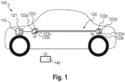
- FIG. 1 shows a radio-based vehicle access system 100 for selectively unlocking and locking the doors and hatches of the vehicle.
- the vehicle access system 100 has an electronic control device 110 in the form of a vehicle control unit and a data bus system 120, which is a LIN bus and via which the control device 110 exchanges data.
- the data bus system 120 has a master module 121, which is an integral part of the control device 110 (see also Figure 2 ).
- the master module 121 is connected to a plurality of radio-based slave modules 122a-122d for data exchange via a preferably three-core cable, wherein the slave modules 122a-122d are installed at different installation positions of the vehicle.
- the slave modules 122a and 122b are located on a common, in Figure 1 left side of the vehicle and the slave modules 122c and 122d on an opposite side, in Figure 1 right side of the vehicle.
- the slave modules 122a-122d each have a radio transceiver 123a-123d for sending and receiving in the UHF band, for example, and thus exchange a coding key with a radio-based vehicle key 140 located outside the vehicle in order to optionally unlock and lock vehicle doors with a valid coding key (not shown).
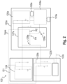
- the data bus system 120 is shown in a schematic block diagram.
- the master module 121 and the Slave modules 122a-122d are arranged in a daisy chain configuration, i.e. connected in series.
- slave modules 122a and 122b are shown here, although the principle described below can be extended to any number of slave modules, as is indicated for slave module 122c, for example, which in turn is connected to the next slave module 122d in the daisy chain configuration. All slave modules 122a-122d are constructed identically, so that they are identical parts. The following explanations for slave modules 122a, 122b can therefore be easily transferred to slave modules 122c, 122d.
- the master module 121 essentially comprises a master bus transceiver 124, which is a known LIN transceiver.
- the slave modules 122a-122d each have a slave bus transceiver 125a-125d in the form of a LIN transceiver.
- each slave module 122a-122d has a microcontroller 126a-126d, which is connected to the respective slave bus transceiver 125a-125d via an input connection and an output connection.
- each slave module 122a-122d has a discrete bus activation circuit 127a-127d, which is arranged on its own circuit board and is made up of discrete components.
- the respective bus activation circuit 127a-127d comprises a first switching element 128a-128d, which is designed here as an n-channel MOSFET. This is connected on the input side to the slave bus transceiver 125a-125d and the microcontroller 126a-126d and on the output side to the slave bus transceiver 125b-125d of the slave module 125b-125d in the daisy chain configuration.
- next slave module 122b-122d next slave module 122b-122d.
- the activation circuit 127a-127d switches the bus connection to the next slave module 122a-122d on or off as required.
- the source connection of the first switching element 128a-128d is connected to the slave bus transceiver 125a-125d of the slave module 122a-122d itself and the gate connection is connected to the positive supply voltage Vpos of the slave module 122a-122d via two resistors R1 and R2 in series or only one resistor.
- the drain connection is connected to the slave bus transceiver 125b-125d of the next slave module 122b-122d.
- the first switching element 128a-128d is controlled via a second switching element 129a-129b, which is designed here as an npn transistor.
- a base connection of the second switching element 129a-129b is connected to an output connection of the microcontroller 126a-126d, the emitter connection is connected to ground and the collector connection is connected between the two resistors or directly to the gate connection of the first switching element 128a-128d.
- the microcontroller 126a-126d switches a positive voltage signal, e.g.
- the second switching element 129a-129d switches through and causes the first switching element 128a-128d to block, thereby breaking the connection between the slave bus transceivers 125b-125d and thus also the connection of the slave bus transceiver 125b-125d of the next slave module 122b-122d to the master bus transceiver 124.
- the respective microcontroller 126a-126d of a preceding slave module 122a-122d in the daisy chain configuration switches the bus connection to the next slave module 122b-122d in the daisy chain configuration on or off via its respective bus activation circuit 127a-127d.
- the relevant control of the microcontroller 126a-126d via the master bus transceiver 124 and the respective slave bus transceiver 125a-125d.
- the slave modules 122a-122d are identical in construction, but are installed in different positions within the vehicle (see Figure 1 ).
- the respective installation position is specified in particular by the wiring harness used by the vehicle manufacturer.
- the teaching of the respective unique installation position is preferably carried out via unique installation position data that are sent out by the master module 121. These are gradually written into the relevant slave module 122a-122d, for which purpose each of them has a flash memory 130a-130d (see Figure 2 ). It is worth noting that at the time of installation of the slave modules 122a-122d the flash memory is blank.
- a step S1 the slave bus transceiver 125b of the slave module 122b, which follows the slave module 122a, is first separated from the master bus transceiver 124 of the master module 121 by applying the voltage to the output connection of the microcontroller 126a of the slave module 122a. As explained above, the first switching element 128a of the slave module 122a then blocks and separates the connection to the slave bus transceiver 125b of the slave module 122b.
- step S2 unique installation position data are fixed, which the first slave module 122a, into the flash memory 130a of the first slave module 122a.
- the slave bus transceiver 122b is then connected to the master bus transceiver 124 by switching off the voltage at the first switching element 128a.
- the master bus transceiver 124 can then also communicate with the next slave module 122b.
- step S4 the unique installation position data identifying the next slave module 122b are then written into the flash memory 130b of the slave module 122b.
- This process is repeated until the correct installation position data is assigned to all slave modules and stored there. This can then be queried via the master module 121 via the data bus.
Landscapes
- Engineering & Computer Science (AREA)
- Computer Networks & Wireless Communication (AREA)
- Signal Processing (AREA)
- Small-Scale Networks (AREA)
- Lock And Its Accessories (AREA)
- Selective Calling Equipment (AREA)
Description
-
US 2009/121776 A1 undWO 2010/009584 A1 offenbaren Datenbusse. - Die Erfindung betrifft das Anlernen einer Einbauposition von Slave-Modulen durch ein funkbasiertes Fahrzeug-Zugangssystem entsprechend dem unabhängigen Anspruch 1 sowie den abhängigen Ansprüchen 2-7.
- In einem Fahrzeug gibt es verschiedene Anwendungsfälle, in denen für eine Fahrzeugfunktion erfüllende Slave-Module eine bestimmte Einbauposition festgelegt sein muss.
- Ein exemplarisches Anwendungsbeispiel ist ein funkbasiertes Fahrzeug-Zugangssystem zum Entriegeln und Verriegeln von Fahrzeugtüren des Fahrzeugs. Ein solches Fahrzeug-Zugangssystem verfügt üblicherweise über mehrere funkbasierte Module in Form von Sendern/Empfängern bzw. Transmittern/Receivern, die über einen Datenbus mit einer dazugehörigen Steuereinrichtung des Fahrzeugs kommunizieren und mit einem funkbasierten Fahrzeugschlüssel interagieren, damit die Steuereinrichtung bei einer gültigen Zugangskodierung die Fahrzeugtüren entriegelt. Um eine möglichst genaue Ortsbestimmung des Fahrzeugschlüssels außerhalb des Fahrzeugs zu ermöglichen, können mehrere der Module eine individuell zugewiesene bzw. vorbestimmte Einbauposition innerhalb des Fahrzeugs haben, über die die Steuereinrichtung die Ortsbestimmung vornehmen kann. Somit unterscheiden sich diese Module zumindest in ihrer Einbauposition, so dass es notwendig ist, jedes Modul individualisiert, z.B. auch mit einer individuellen Logistik-Teilenummer, zur Verfügung zu stellen und dieses genau an der individuellen Einbauposition zu verbauen. Dies kann neben dem hohen logistischen Aufwand auch zu einer erhöhten Fehleranfälligkeit hinsichtlich des individuellen Einbauorts führen, wenn z.B. die jeweiligen Einbaupositionen der Module vertauscht werden.
- Es ist daher eine Aufgabe der Erfindung, unter Einsatz konstruktiv möglichst einfacher Mittel eine Möglichkeit zum Anlernen einer Einbauposition von Modulen in einem Fahrzeug zu schaffen.
- Diese Aufgabe wird durch die Gegenstände der unabhängigen und der nebengeordneten Ansprüche gelöst. Vorteilhafte Weiterbildungen und Ausführungsformen sind in den abhängigen Ansprüchen, der nachfolgenden Beschreibung und den begleitenden Figuren angegeben.
- Die Erfindung bezieht sich auf ein funkbasiertes Fahrzeug-Zugangssystem. Dieses kann vorzugsweise das UHF-Band, das Bluetooth Low Energy (BLE) - System oder das Ultra Wideband (UWB) nutzen. Prinzipiell dient das Fahrzeug-Zugangssystem dazu, nur berechtigten Nutzern, die sich im Besitz eines passend kodierten Fahrzeugschlüssels befinden, Zugang zu dem Fahrzeug zu gewähren.
- Das Fahrzeug-Zugangssystem weist eine Steuereinrichtung, wie z.B. ein Steuergerät des Fahrzeugs, wie etwa einen Body-Controller auf, zum wahlweisen Entriegeln und Verriegeln von Fahrzeugtüren, wobei dies indirekt über die Ansteuerung von Aktoren bzw. der Türschlösser erfolgen kann. Zudem verfügt das Fahrzeug-Zugangssystem über das oben beschriebene Datenbus-System in einer oder mehreren der oben erläuterten Ausführungsvarianten. Dabei weisen die oben beschriebenen Slave-Module des Datenbus-Systems ferner jeweils einen mit der Steuereinrichtung verbundenen Funk-Transceiver für eine Funkverbindung mit dem Fahrzeugschlüssel oder einen anderem Gerät mit Funktransceiver auf.
- Z.B. aufgrund einer geringen Sendeleistung der verwendeten Funktechnik kann es notwendig sein, mehrere der oben genannten Slave-Module an verschiedenen Einbaupositionen innerhalb des Fahrzeugs zu positionieren. Da sich diese - wie oben für das Datenbus-System beschrieben - nach dem Verbauen über das Datenbus-System anlernen lassen, können die Slave-Module vorteilhafterweise baugleich ausgeführt sein. Damit können die Slave-Module mit einer einzigen, einheitlichen Logistik-Teilenummer ausgeliefert und mit geringem Montageaufwand beim Fahrzeughersteller verbaut werden.
- Weitere Merkmale, Vorteile und Anwendungsmöglichkeiten der Erfindung ergeben sich aus der nachfolgenden Beschreibung der Ausführungsbeispiele und Figuren. Dabei bilden alle beschriebenen und/oder bildlich dargestellten Merkmale für sich und in beliebiger Kombination den Gegenstand der Erfindung auch unabhängig von ihrer Zusammensetzung in den einzelnen Ansprüchen oder deren Rückbezügen.
- Im Folgenden wird die Erfindung anhand einer Zeichnung näher erläutert. Es zeigen:
- Fig. 1
- ein Fahrzeug-Zugangssystem 100, das eine Steuereinrichtung und ein Daten-Bussystem aufweist für ein Ausführungsbeispiel der Erfindung,
- Fig. 2
- ein Blockschaubild eins Daten-Bussystems mit einem Schaltbild einer Bus-Aktivierungsschaltung für ein Ausführungsbeispiel der Erfindung, und
- Fig. 3
- ein Flussdiagramm für ein Verfahren gemäß einem Ausführungsbeispiel der Erfindung.
- Die Figuren sind lediglich schematische Darstellungen und dienen nur der Erläuterung von Ausführungsbeispielen der Erfindung der Erfindung. Gleiche oder gleichwirkende Elemente sind durchgängig mit den gleichen Bezugszeichen versehen.
-
Figur 1 zeigt ein funkbasiertes Fahrzeug-Zugangssystem 100 zum wahlweisen Entriegeln und Verriegeln von Türen- und Klappen des Fahrzeugs. Das Fahrzeug-Zugangssystem 100 weist eine elektronische Steuereinrichtung 110 in Form eines Fahrzeug-Steuergeräts und ein Daten-Bussystem 120 auf, bei dem es sich hier um einen LIN-Bus handelt und über das die Steuereinrichtung 110 Daten austauscht. - Das Daten-Bussystem 120 verfügt über ein Master-Modul 121, das hier integrativer Teil der Steuereinrichtung 110 ist (siehe auch
Figur 2 ). Das Master-Modul 121 ist über ein vorzugsweise dreiadriges Kabel mit einer Mehrzahl von funkbasierten Slave-Modulen 122a-122d zum Datenaustausch verbunden, wobei die Slave-Module 122a-122d an zueinander unterschiedlichen Einbaupositionen des Fahrzeugs verbaut sind. Wie inFigur 1 angedeutet, befinden sich exemplarisch die Slave-Module 122a und 122b auf einer gemeinsamen, inFigur 1 linken Fahrzeugseite und die Slave-Module 122c und 122d auf einer dazu gegenüberliegenden, inFigur 1 rechten Fahrzeugseite. Zudem verfügen die Slave-Module 122a-122d jeweils über einen Funk-Transceiver 123a-123d zum Senden und Empfangen im z.B. UHF-Band und tauschen so einen Kodierungsschlüssel mit einem außerhalb des Fahrzeugs befindlichen funkbasierten Fahrzeugschlüssel 140 aus, um bei einem gültigen Kodierungsschlüssel (nicht gezeigte) Fahrzeugtüren wahlweise zu entriegeln und verriegeln. - In
Figur 2 ist das Daten-Bussystem 120 in einem schematischen Blockschaltbild dargestellt. Das Master-Modul 121 und die Slave-Module 122a-122d sind in einer Daisy-Chain-Konfiguration angeordnet, also in Serie miteinander verbunden. Der Übersichtlichkeit halber sind hier nur die Slave-Module 122a und 122b gezeigt, wobei das nachfolgend beschriebene Prinzip auf beliebig viele Slave-Module erweiterbar ist, wie dies z.B. für das Slave-Modul 122c angedeutet ist, das wiederum mit dem in der Daisy-Chain-Konfiguration nächstfolgenden Slave-Modul 122d verbunden ist. Dabei sind sämtliche Slave-Module 122a-122d baugleich ausgeführt, so dass es sich um Gleichteile handelt. Die nachfolgenden Ausführungen zu den Slave-Modulen 122a, 122b sind deshalb ohne Weiteres auf die Slave-Module 122c, 122d übertragbar. - Das Master-Modul 121 umfasst im Wesentlichen einen Master-Bus-Transceiver 124, bei dem es sich hier um einen an sich bekannten LIN-Transceiver handelt. Ebenso weisen die Slave-Module 122a-122d jeweils einen Slave-Bus-Transceiver 125a-125d in Form eines LIN-Transceivers auf.
- Darüber hinaus verfügt jedes Slave-Modul 122a-122d über einen Mikrocontroller 126a-126d, der über jeweils einen Eingangsanschluss und Ausgangsanschluss mit dem jeweiligen Slave-Bus-Transceiver 125a-125d verbunden ist.
- Zum Zu- oder Abschalten des in der Daisy-Chain-Konfiguration nächstfolgenden Slave-Moduls 122b-122d weist jedes Slave-Modul 122a-122d eine diskret ausgeführte Bus-Aktivierungsschaltung 127a-127d, die auf einer eigenen Leiterplatte angeordnet und aus diskreten Bauelementen aufgebaut ist. Die jeweilige Bus-Aktivierungsschaltung 127a-127d umfasst ein erstes Schaltelement 128a-128d, das hier als n-Kanal-MOSFET ausgeführt ist. Dieses ist eingangsseitig mit dem Slave-Bus-Transceiver 125a-125d sowie dem Mikrocontroller 126a-126d und ausgangsseitig mit dem Slave-Bus-Transceiver 125b-125d des in der Daisy-Chain-Konfiguration nächstfolgenden Slave-Moduls 122b-122d verbunden. In anderen Worten, schaltet die Aktivierungsschaltung 127a-127d die Bus-Verbindung zu dem nächstfolgenden Slave-Modul 122a-122d wahlweise aus oder ein. Hierzu sind der Source-Anschluss des ersten Schaltelements 128a-128d mit dem Slave-Bus-Transceiver 125a-125d des eigenen Slave-Moduls 122a-122d verbunden und der Gate-Anschluss über zwei Widerstände R1 und R2 in Serie oder nur einen Widerstand mit der positiven Versorgungsspannung Vpos des Slave-Moduls 122a-122d verbunden. Der Drain-Anschluss ist mit dem Slave-Bus-Transceiver 125b-125d des nächstfolgenden Slave-Moduls 122b-122d verbunden.
- Die Ansteuerung des ersten Schaltelements 128a-128d erfolgt jeweils über ein zweites Schaltelement 129a-129b, das hier als npn-Transistor ausgeführt ist. Ein Basis-Anschluss des zweiten Schaltelements 129a-129b ist mit einem Ausgangsanschluss des Mikrocontrollers 126a-126d, der Emitter-Anschluss mit Masse und der Kollektor-Anschluss ist zwischen den beiden Widerständen oder direkt mit dem Gate-Anschluss des ersten Schaltelements 128a-128d verbunden. Wenn der Mikrocontroller 126a-126d ein positives Spannungssignal, z.B. 5V, an seinen Ausgangsanschluss schaltet, schaltet das zweite Schaltelement 129a-129d durch und bewirkt, dass das erste Schaltelement 128a-128d sperrt, wodurch die Verbindung zwischen den Slave-Bus-Transceivern 125b-125d und damit auch die Verbindung des Slave-Bus-Transceivers 125b-125d des nächstfolgenden Slave-Moduls 122b-122d zu dem Master-Bus-Transceiver 124 getrennt werden.
- Funktional betrachtet, schaltet der jeweilige Microcontroller 126a-126d eines in der Daisy-Chain-Konfiguration vorangehenden Slave-Modul 122a-122d über seine jeweilige Bus-Aktivierungsschaltung 127a-127d die Bus-Verbindung zu dem in der Daisy-Chain-Konfiguration nächstfolgenden Slave-Modul 122b-122d wahlweise ab oder zu. Die diesbezügliche Ansteuerung des Mikrocontrollers 126a-126d erfolgt über den Master-Bus-Transceiver 124 und den jeweiligen Slave-Bus-Transceiver 125a-125d.
- Anhand der
Figuren 2 und3 , wobeiFigur 3 ein Flussdiagramm mit den Schritten des Verfahrens zeigt, wird im Folgenden ein beispielhaftes Verfahren zum Anlernen einer eineindeutigen Einbauposition des jeweiligen Slave-Moduls 122a-122d erläutert. - Wie oben ausgeführt, sind die Slave-Module 122a-122d baugleich, jedoch an unterschiedlichen Einbaupositionen innerhalb des Fahrzeugs verbaut (vgl.
Figur 1 ). Dabei ist die jeweilige Einbauposition insbesondere durch den vom Fahrzeughersteller verwendeten Leitungssatz bzw. Kabelbaum vorgegeben. Das Anlernen der jeweils eineindeutigen Einbauposition erfolgt vorzugsweise über eineindeutige Einbaupositions-Daten, die von dem Master-Modul 121 ausgesendet werden. Diese werden nach und nach in das betreffende Slave-Modul 122a-122d festgeschrieben, wozu diese jeweils einen Flash-Speicher 130a-130d aufweisen (sieheFigur 2 ). Beachtenswert ist, dass zum Zeitpunkt des Einbaus der Slave-Module 122a-122d der Flash-Speicher unbeschrieben ist. - In einem Schritt S1 erfolgt zunächst ein Trennen des hier auf das Slave-Modul 122a nächstfolgenden Slave-Bus-Transceivers 125b des Slave-Moduls 122b von dem Master-Bus-Transceiver 124 des Master-Moduls 121 durch Aufschalten der Spannung am Ausgangsanschluss des Mikrocontrollers 126a des Slave-Moduls 122a. Wie oben erläutert, sperrt das erste Schaltelement 128a des Slave-Moduls 122a daraufhin und trennt die Verbindung zu dem Slave-Bus-Transceiver 125b des Slave-Moduls 122b.
- Dann erfolgt in einem Schritt S2 ein Festschreiben von eineindeutigen Einbaupositions-Daten, die das erste Slave-Modul 122a kennzeichnen, in den Flash-Speicher 130a des ersten Slave-Moduls 122a.
- In einem Schritt S3 erfolgt dann ein Verbinden des Slave-Bus-Transceivers 122b mit dem Master-Bus-Transceiver 124 durch Abschalten der Spannung an dem ersten Schaltelement 128a. Damit kann der Master-Bus-Transceiver 124 nun auch mit dem nächstfolgenden Slave-Modul 122b kommunizieren.
- In einem Schritt S4 werden dann die das nächstfolgende Slave-Modul 122b kennzeichnenden, eineindeutigen Einbaupositions-Daten in den Flash-Speicher 130b des Slave-Moduls 122b festgeschrieben.
- Dieses Verfahren wird so oft wiederholt, bis sämtlichen Slave-Modulen die korrekten Einbaupositions-Daten zugeordnet und dort festgeschrieben sind. Diese können dann über das Master-Modul 121 über den Datenbus abgefragt werden.
- Ergänzend sei darauf hinzuweisen, dass "umfassend" oder "aufweisend" keine anderen Elemente ausschließt und "ein" oder "einer" keine Vielzahl ausschließt. Ferner sei darauf hingewiesen, dass Merkmale, die mit Verweis auf eines der obigen Ausführungsbeispiele oder Ausführungsformen beschrieben worden sind, auch in Kombination mit anderen Merkmalen anderer oben beschriebener Ausführungsbeispiele oder Ausführungsformen verwendet werden können. Bezugszeichen in den Ansprüchen sind nicht als Einschränkungen anzusehen.
Claims (7)
- Funkbasiertes Fahrzeug-Zugangssystem (100), aufweisend- ein Datenbus-System (120) aufweisend- ein Master-Modul (121) mit einem Master-Bus-Transceiver (124), und- wenigstens ein erstes Slave-Modul (122a) sowie ein dazu baugleiches, zweites Slave-Modul (122b), die in einer Daisy-Chain-Konfiguration mit dem Master-Modul (121) angeordnet sind,- wobei das erste Slave-Modul (122a) eine diskret ausgeführte Bus-Aktivierungsschaltung (127a) mit einem ersten Schaltelement (128a) aufweist, das eingangsseitig mit einem ersten Slave-Bus-Transceiver (125a) sowie über diesen mit einem ersten Mikrocontroller (126a) des ersten Slave-Moduls (122a) und ausgangsseitig mit einem zweiten Slave-Bus-Transceiver (125b) des zweiten Slave-Moduls (122b) verbunden ist,
und
wobei das erste Schaltelement (128a) zum wahlweisen Verbinden und Trennen des zweiten Slave-Bus-Transceivers (125b) mit dem Master-Bus-Transceiver (124) durch ein Spannungssignal des ersten Mikrocontrollers (126a) ansteuerbar ist,
ferner aufweisend- eine Steuereinrichtung (110) zum wahlweisen Entriegeln und Verriegeln von Fahrzeugtüren, die mit dem Datenbus-System (120) verbunden ist, wobei das Master-Modul (121) integrativer Teil der Steuereinrichtung (110) ist,
wobei Fahrzeugtüren insofern mit dem Datenbus-System (120) verbunden sind, dass die Fahrzeugtüren mit der Steuereinrichtung des Datenbus-Systems (120) verbunden sind, zum wahlweisen Entriegeln und Verriegeln der Fahrzeugtüren durch die Steuereinrichtung,- wobei die Slave-Module (122a-122d) des Datenbus-Systems (120), die über das Datenbus-System (120) mit der Steuereinrichtung (110) verbunden sind, ferner jeweils einen über das Datenbussystem (110) verbundenen Funk-Transceiver (123a-123d) zum Senden und Empfangen aufweisen, um einen Kodierungsschlüssel mit einem außerhalb des Fahrzeugs befindlichen funkbasierten Fahrzeugschlüssel (140) auszutauschen,wobei der Kodierungsschlüssel zum wahlweises Entriegeln und Verriegeln von Fahrzeugtüren durch die Steuereinrichtung vorgesehen ist. - Funkbasiertes Fahrzeug-Zugangssystem (100) nach Anspruch 1, wobei der erste Mikrocontroller (126a) dazu eingerichtet ist, die Verbindung zwischen dem zweiten Slave-Bus-Transceiver (125b) und dem Master-Bus-Transceiver (124) zu trennen, wenn das Bus-Mastermodul (121) eineindeutige, erste Einbaupositions-Daten zum Festschreiben in dem ersten Slave-Modul (122a) aussendet.
- Funkbasiertes Fahrzeug-Zugangssystem (100) nach Anspruch 1 oder 2, wobei der erste Mikrocontroller (126a) dazu eingerichtet ist, den zweiten Slave-Bus-Transceiver (125b) mit dem Master-Bus-Transceiver (124) zu verbinden, wenn das Bus-Mastermodul (121) eineindeutige, zweite Einbaupositions-Daten zum Festschreiben in dem zweiten Slave-Modul (122b) aussendet.
- Funkbasiertes Fahrzeug-Zugangssystem (100) nach einem der vorhergehenden Ansprüche, wobei das erste und zweite Slave-Modul (122a, 122b) jeweils einen Flash-Speicher (130a, 130b) aufweisen, in dem eine eineindeutige Einbaupositions-Kennung des jeweiligen Slave-Moduls festschreibbar ist.
- Funkbasiertes Fahrzeug-Zugangssystem (100) nach einem der vorhergehenden Ansprüche, wobei die Bus-Aktivierungsschaltung (127a-127d) auf einer zu dem jeweiligen Slave-Bus-Transceiver (125a-125d) und/oder dem jeweiligen Mikrocontroller (126a-126d) separaten Leiterplatte angeordnet ist.
- Funkbasiertes Fahrzeug-Zugangssystem (100) nach einem der vorhergehenden Ansprüche, wobei das erste Schaltelement (128a-128d) ein n-Kanal-Feldeffekttransistor ist.
- Funkbasiertes Fahrzeug-Zugangssystem (100) nach einem der vorhergehenden Ansprüche, wobei die Bus-Aktivierungsschaltung (127a-127d) ferner ein zwischen dem ersten Mikrocontroller (126a-126d) und dem ersten Schaltelement (128a-128d) angeordnetes, diskretes zweites Schaltelement (129a-129d) zum Ansteuern des ersten Schaltelements (128a-128d) aufweist.
Applications Claiming Priority (2)
| Application Number | Priority Date | Filing Date | Title |
|---|---|---|---|
| DE102018205082.1A DE102018205082B4 (de) | 2018-04-04 | 2018-04-04 | Fahrzeug-Zugangssystem mit Datenbus-System zum Anlernen einer eineindeutigen Einbauposition |
| PCT/EP2019/057732 WO2019192907A1 (de) | 2018-04-04 | 2019-03-27 | Datenbus-system für ein fahrzeug, fahrzeug-zugangssystem sowie verfahren zum anlernen einer eineindeutigen einbauposition |
Publications (2)
| Publication Number | Publication Date |
|---|---|
| EP3777050A1 EP3777050A1 (de) | 2021-02-17 |
| EP3777050B1 true EP3777050B1 (de) | 2024-08-14 |
Family
ID=66041450
Family Applications (1)
| Application Number | Title | Priority Date | Filing Date |
|---|---|---|---|
| EP19715429.7A Active EP3777050B1 (de) | 2018-04-04 | 2019-03-27 | Datenbus-system für ein fahrzeug |
Country Status (3)
| Country | Link |
|---|---|
| EP (1) | EP3777050B1 (de) |
| DE (1) | DE102018205082B4 (de) |
| WO (1) | WO2019192907A1 (de) |
Families Citing this family (3)
| Publication number | Priority date | Publication date | Assignee | Title |
|---|---|---|---|---|
| CN112423279B (zh) * | 2020-10-14 | 2022-05-03 | 奇瑞汽车股份有限公司 | 一种识别蓝牙从模块安装位置的方法 |
| CN115460044B (zh) * | 2022-08-31 | 2023-06-06 | 重庆长安汽车股份有限公司 | 基于soc芯片的车载网关、控制方法及车载装置 |
| EP4421303A1 (de) | 2023-02-24 | 2024-08-28 | Liebherr-Components Colmar SAS | System zur überprüfung der korrekten montage eines sensors |
Family Cites Families (6)
| Publication number | Priority date | Publication date | Assignee | Title |
|---|---|---|---|---|
| US7746114B2 (en) * | 2007-11-14 | 2010-06-29 | Denso Corporation | Bus switch and electronic switch |
| CN101635637A (zh) * | 2008-07-21 | 2010-01-27 | 江森自控楼宇设备科技(无锡)有限公司 | 基于串行总线的智能地址分配的方法和系统 |
| US8935450B2 (en) | 2011-09-16 | 2015-01-13 | Nxp B.V. | Network communications circuit, system and method |
| US9331866B2 (en) | 2012-04-20 | 2016-05-03 | Nxp B.V. | Network communications apparatus, system, and method |
| US9514086B2 (en) * | 2013-03-13 | 2016-12-06 | Atieva, Inc. | Configuration switch for a broadcast bus |
| DE102017112802A1 (de) | 2017-02-09 | 2018-08-09 | Huf Hülsbeck & Fürst Gmbh & Co. Kg | Verfahren zur Positionsbestimmung eines mobilen BLE-Geräts relativ zu einem Fahrzeug |
-
2018
- 2018-04-04 DE DE102018205082.1A patent/DE102018205082B4/de active Active
-
2019
- 2019-03-27 EP EP19715429.7A patent/EP3777050B1/de active Active
- 2019-03-27 WO PCT/EP2019/057732 patent/WO2019192907A1/de not_active Ceased
Also Published As
| Publication number | Publication date |
|---|---|
| DE102018205082A1 (de) | 2019-10-10 |
| EP3777050A1 (de) | 2021-02-17 |
| DE102018205082B4 (de) | 2020-01-02 |
| WO2019192907A1 (de) | 2019-10-10 |
Similar Documents
| Publication | Publication Date | Title |
|---|---|---|
| WO2011012262A1 (de) | Vorrichtung und verfahren zur adressierung einer slave-einheit | |
| DE102017117128A1 (de) | Drahtlose Vergabe von Netzwerkadressen | |
| DE102018205082B4 (de) | Fahrzeug-Zugangssystem mit Datenbus-System zum Anlernen einer eineindeutigen Einbauposition | |
| WO2013092812A1 (de) | Teilnehmerstation eines bussystems und verfahren zur übertragung von nachrichten zwischen teilnehmerstationen eines bussystems | |
| DE10258753A1 (de) | Verteiltes Steuergerät | |
| DE102008036678A1 (de) | Systemarchitektur für Kraftfahrzeuge mit Freigabeschnittstellen für deren Inbetriebnahme | |
| EP1849665B1 (de) | Systemarchitektur für ein Keyless-Go-System | |
| DE102006023274B4 (de) | Verfahren und Vorrichtung zum Steuern von Netzwerksegmenten eines Netzwerks in einem Kraftfahrzeug | |
| DE102013211772A1 (de) | Verfahren und Vorrichtung zum Austausch von Daten in einem Kraftfahrzeug zum Betreiben eines Aktors, vorzugsweise einer automatisierten Reibungskupplung und/oder eines automatisierten Getriebes | |
| EP0923054B1 (de) | Verfahren und Vorrichtung zur Prüfung der Nutzungsberechtigung für Zugangskontrolleinrichtungen | |
| WO2001093065A2 (de) | Verfahren zum datenaustausch zwischen mehreren teilnehmern | |
| DE4344904A1 (de) | System zur Ankopplung von Aktoren und Sensoren an einen Feldbus | |
| EP2962162B1 (de) | Verfahren zur einrichtung oder aktualisierung einer programmierung eines steuergerätes eines verkehrsmittels | |
| DE10123802B4 (de) | Steuerungssystem für Kfz-Komponenten und Steuerungsverfahren | |
| DE102006020562A1 (de) | Anordnung und Verfahren zur Reprogrammierung von Steuergeräten | |
| DE102005038183A1 (de) | Verfahren zum Betreiben eines Netzwerks | |
| DE102010038323B4 (de) | Geräteidentifikationsverfahren eines Slaves innerhalb eines nach dem AS-Interface Standard ausgeführten Feldbussystems | |
| EP1290832A1 (de) | Verfahren zum datenaustausch zwischen mehreren teilnehmern mittels eines datenbusses | |
| DE102017109297A1 (de) | Relaisschaltkastenanordnung | |
| DE10303960A1 (de) | Zugangskontrollsystem | |
| DE102015216667A1 (de) | Verfahren zur Installation einer Funktionssoftware in einem Steuergerät eines Fahrzeuges, vorzugsweise eines Getriebesteuergerätes oder eines Kupplungssteuergerätes | |
| DE10041436A1 (de) | Datensichtanordnung und Verfahren zum Ermitteln der örtlichen Position einer Datensichteinheit innerhalb einer Datensichtanordnung mit einer Vielzahl von Datensichteinheiten | |
| EP1642422B1 (de) | Anpassung eines fahrzeugnetzwerks an geänderte anforderungen | |
| EP2456187B1 (de) | Verfahren zum Einrichten eines aus mindestens einer Türstation und mindestens einer Wohnungsstation zu bildenden Haus-Kommunikationssystems | |
| DE102006032354A1 (de) | Funk-Steuerungssystem |
Legal Events
| Date | Code | Title | Description |
|---|---|---|---|
| STAA | Information on the status of an ep patent application or granted ep patent |
Free format text: STATUS: UNKNOWN |
|
| STAA | Information on the status of an ep patent application or granted ep patent |
Free format text: STATUS: THE INTERNATIONAL PUBLICATION HAS BEEN MADE |
|
| PUAI | Public reference made under article 153(3) epc to a published international application that has entered the european phase |
Free format text: ORIGINAL CODE: 0009012 |
|
| STAA | Information on the status of an ep patent application or granted ep patent |
Free format text: STATUS: REQUEST FOR EXAMINATION WAS MADE |
|
| 17P | Request for examination filed |
Effective date: 20201104 |
|
| AK | Designated contracting states |
Kind code of ref document: A1 Designated state(s): AL AT BE BG CH CY CZ DE DK EE ES FI FR GB GR HR HU IE IS IT LI LT LU LV MC MK MT NL NO PL PT RO RS SE SI SK SM TR |
|
| AX | Request for extension of the european patent |
Extension state: BA ME |
|
| DAV | Request for validation of the european patent (deleted) | ||
| DAX | Request for extension of the european patent (deleted) | ||
| STAA | Information on the status of an ep patent application or granted ep patent |
Free format text: STATUS: EXAMINATION IS IN PROGRESS |
|
| 17Q | First examination report despatched |
Effective date: 20211022 |
|
| RAP1 | Party data changed (applicant data changed or rights of an application transferred) |
Owner name: CONTINENTAL AUTOMOTIVE TECHNOLOGIES GMBH |
|
| REG | Reference to a national code |
Ref country code: DE Ipc: H04L0012403000 Ref country code: DE Ref legal event code: R079 Ref document number: 502019011892 Country of ref document: DE Free format text: PREVIOUS MAIN CLASS: H04L0012400000 Ipc: H04L0012403000 |
|
| RAP3 | Party data changed (applicant data changed or rights of an application transferred) |
Owner name: CONTINENTAL AUTOMOTIVE TECHNOLOGIES GMBH |
|
| GRAP | Despatch of communication of intention to grant a patent |
Free format text: ORIGINAL CODE: EPIDOSNIGR1 |
|
| STAA | Information on the status of an ep patent application or granted ep patent |
Free format text: STATUS: GRANT OF PATENT IS INTENDED |
|
| RIC1 | Information provided on ipc code assigned before grant |
Ipc: H04L 12/403 20060101AFI20240418BHEP |
|
| INTG | Intention to grant announced |
Effective date: 20240508 |
|
| GRAS | Grant fee paid |
Free format text: ORIGINAL CODE: EPIDOSNIGR3 |
|
| GRAA | (expected) grant |
Free format text: ORIGINAL CODE: 0009210 |
|
| STAA | Information on the status of an ep patent application or granted ep patent |
Free format text: STATUS: THE PATENT HAS BEEN GRANTED |
|
| AK | Designated contracting states |
Kind code of ref document: B1 Designated state(s): AL AT BE BG CH CY CZ DE DK EE ES FI FR GB GR HR HU IE IS IT LI LT LU LV MC MK MT NL NO PL PT RO RS SE SI SK SM TR |
|
| REG | Reference to a national code |
Ref country code: GB Ref legal event code: FG4D Free format text: NOT ENGLISH |
|
| REG | Reference to a national code |
Ref country code: CH Ref legal event code: EP |
|
| REG | Reference to a national code |
Ref country code: DE Ref legal event code: R096 Ref document number: 502019011892 Country of ref document: DE |
|
| REG | Reference to a national code |
Ref country code: IE Ref legal event code: FG4D Free format text: LANGUAGE OF EP DOCUMENT: GERMAN |
|
| REG | Reference to a national code |
Ref country code: LT Ref legal event code: MG9D |
|
| REG | Reference to a national code |
Ref country code: NL Ref legal event code: MP Effective date: 20240814 |
|
| PG25 | Lapsed in a contracting state [announced via postgrant information from national office to epo] |
Ref country code: NO Free format text: LAPSE BECAUSE OF FAILURE TO SUBMIT A TRANSLATION OF THE DESCRIPTION OR TO PAY THE FEE WITHIN THE PRESCRIBED TIME-LIMIT Effective date: 20241114 |
|
| PG25 | Lapsed in a contracting state [announced via postgrant information from national office to epo] |
Ref country code: GR Free format text: LAPSE BECAUSE OF FAILURE TO SUBMIT A TRANSLATION OF THE DESCRIPTION OR TO PAY THE FEE WITHIN THE PRESCRIBED TIME-LIMIT Effective date: 20241115 Ref country code: NL Free format text: LAPSE BECAUSE OF FAILURE TO SUBMIT A TRANSLATION OF THE DESCRIPTION OR TO PAY THE FEE WITHIN THE PRESCRIBED TIME-LIMIT Effective date: 20240814 Ref country code: FI Free format text: LAPSE BECAUSE OF FAILURE TO SUBMIT A TRANSLATION OF THE DESCRIPTION OR TO PAY THE FEE WITHIN THE PRESCRIBED TIME-LIMIT Effective date: 20240814 Ref country code: PL Free format text: LAPSE BECAUSE OF FAILURE TO SUBMIT A TRANSLATION OF THE DESCRIPTION OR TO PAY THE FEE WITHIN THE PRESCRIBED TIME-LIMIT Effective date: 20240814 Ref country code: PT Free format text: LAPSE BECAUSE OF FAILURE TO SUBMIT A TRANSLATION OF THE DESCRIPTION OR TO PAY THE FEE WITHIN THE PRESCRIBED TIME-LIMIT Effective date: 20241216 |
|
| PG25 | Lapsed in a contracting state [announced via postgrant information from national office to epo] |
Ref country code: BG Free format text: LAPSE BECAUSE OF FAILURE TO SUBMIT A TRANSLATION OF THE DESCRIPTION OR TO PAY THE FEE WITHIN THE PRESCRIBED TIME-LIMIT Effective date: 20240814 |
|
| PG25 | Lapsed in a contracting state [announced via postgrant information from national office to epo] |
Ref country code: LV Free format text: LAPSE BECAUSE OF FAILURE TO SUBMIT A TRANSLATION OF THE DESCRIPTION OR TO PAY THE FEE WITHIN THE PRESCRIBED TIME-LIMIT Effective date: 20240814 |
|
| PG25 | Lapsed in a contracting state [announced via postgrant information from national office to epo] |
Ref country code: IS Free format text: LAPSE BECAUSE OF FAILURE TO SUBMIT A TRANSLATION OF THE DESCRIPTION OR TO PAY THE FEE WITHIN THE PRESCRIBED TIME-LIMIT Effective date: 20241214 |
|
| PG25 | Lapsed in a contracting state [announced via postgrant information from national office to epo] |
Ref country code: HR Free format text: LAPSE BECAUSE OF FAILURE TO SUBMIT A TRANSLATION OF THE DESCRIPTION OR TO PAY THE FEE WITHIN THE PRESCRIBED TIME-LIMIT Effective date: 20240814 |
|
| PG25 | Lapsed in a contracting state [announced via postgrant information from national office to epo] |
Ref country code: RS Free format text: LAPSE BECAUSE OF FAILURE TO SUBMIT A TRANSLATION OF THE DESCRIPTION OR TO PAY THE FEE WITHIN THE PRESCRIBED TIME-LIMIT Effective date: 20241114 Ref country code: ES Free format text: LAPSE BECAUSE OF FAILURE TO SUBMIT A TRANSLATION OF THE DESCRIPTION OR TO PAY THE FEE WITHIN THE PRESCRIBED TIME-LIMIT Effective date: 20240814 |
|
| PG25 | Lapsed in a contracting state [announced via postgrant information from national office to epo] |
Ref country code: RS Free format text: LAPSE BECAUSE OF FAILURE TO SUBMIT A TRANSLATION OF THE DESCRIPTION OR TO PAY THE FEE WITHIN THE PRESCRIBED TIME-LIMIT Effective date: 20241114 Ref country code: PT Free format text: LAPSE BECAUSE OF FAILURE TO SUBMIT A TRANSLATION OF THE DESCRIPTION OR TO PAY THE FEE WITHIN THE PRESCRIBED TIME-LIMIT Effective date: 20241216 Ref country code: PL Free format text: LAPSE BECAUSE OF FAILURE TO SUBMIT A TRANSLATION OF THE DESCRIPTION OR TO PAY THE FEE WITHIN THE PRESCRIBED TIME-LIMIT Effective date: 20240814 Ref country code: NO Free format text: LAPSE BECAUSE OF FAILURE TO SUBMIT A TRANSLATION OF THE DESCRIPTION OR TO PAY THE FEE WITHIN THE PRESCRIBED TIME-LIMIT Effective date: 20241114 Ref country code: NL Free format text: LAPSE BECAUSE OF FAILURE TO SUBMIT A TRANSLATION OF THE DESCRIPTION OR TO PAY THE FEE WITHIN THE PRESCRIBED TIME-LIMIT Effective date: 20240814 Ref country code: LV Free format text: LAPSE BECAUSE OF FAILURE TO SUBMIT A TRANSLATION OF THE DESCRIPTION OR TO PAY THE FEE WITHIN THE PRESCRIBED TIME-LIMIT Effective date: 20240814 Ref country code: IS Free format text: LAPSE BECAUSE OF FAILURE TO SUBMIT A TRANSLATION OF THE DESCRIPTION OR TO PAY THE FEE WITHIN THE PRESCRIBED TIME-LIMIT Effective date: 20241214 Ref country code: HR Free format text: LAPSE BECAUSE OF FAILURE TO SUBMIT A TRANSLATION OF THE DESCRIPTION OR TO PAY THE FEE WITHIN THE PRESCRIBED TIME-LIMIT Effective date: 20240814 Ref country code: GR Free format text: LAPSE BECAUSE OF FAILURE TO SUBMIT A TRANSLATION OF THE DESCRIPTION OR TO PAY THE FEE WITHIN THE PRESCRIBED TIME-LIMIT Effective date: 20241115 Ref country code: FI Free format text: LAPSE BECAUSE OF FAILURE TO SUBMIT A TRANSLATION OF THE DESCRIPTION OR TO PAY THE FEE WITHIN THE PRESCRIBED TIME-LIMIT Effective date: 20240814 Ref country code: ES Free format text: LAPSE BECAUSE OF FAILURE TO SUBMIT A TRANSLATION OF THE DESCRIPTION OR TO PAY THE FEE WITHIN THE PRESCRIBED TIME-LIMIT Effective date: 20240814 Ref country code: BG Free format text: LAPSE BECAUSE OF FAILURE TO SUBMIT A TRANSLATION OF THE DESCRIPTION OR TO PAY THE FEE WITHIN THE PRESCRIBED TIME-LIMIT Effective date: 20240814 |
|
| PGFP | Annual fee paid to national office [announced via postgrant information from national office to epo] |
Ref country code: DE Payment date: 20250331 Year of fee payment: 7 |
|
| PG25 | Lapsed in a contracting state [announced via postgrant information from national office to epo] |
Ref country code: RO Free format text: LAPSE BECAUSE OF FAILURE TO SUBMIT A TRANSLATION OF THE DESCRIPTION OR TO PAY THE FEE WITHIN THE PRESCRIBED TIME-LIMIT Effective date: 20240814 Ref country code: SM Free format text: LAPSE BECAUSE OF FAILURE TO SUBMIT A TRANSLATION OF THE DESCRIPTION OR TO PAY THE FEE WITHIN THE PRESCRIBED TIME-LIMIT Effective date: 20240814 Ref country code: DK Free format text: LAPSE BECAUSE OF FAILURE TO SUBMIT A TRANSLATION OF THE DESCRIPTION OR TO PAY THE FEE WITHIN THE PRESCRIBED TIME-LIMIT Effective date: 20240814 |
|
| PG25 | Lapsed in a contracting state [announced via postgrant information from national office to epo] |
Ref country code: EE Free format text: LAPSE BECAUSE OF FAILURE TO SUBMIT A TRANSLATION OF THE DESCRIPTION OR TO PAY THE FEE WITHIN THE PRESCRIBED TIME-LIMIT Effective date: 20240814 |
|
| PG25 | Lapsed in a contracting state [announced via postgrant information from national office to epo] |
Ref country code: CZ Free format text: LAPSE BECAUSE OF FAILURE TO SUBMIT A TRANSLATION OF THE DESCRIPTION OR TO PAY THE FEE WITHIN THE PRESCRIBED TIME-LIMIT Effective date: 20240814 |
|
| PGFP | Annual fee paid to national office [announced via postgrant information from national office to epo] |
Ref country code: FR Payment date: 20250326 Year of fee payment: 7 |
|
| PG25 | Lapsed in a contracting state [announced via postgrant information from national office to epo] |
Ref country code: SK Free format text: LAPSE BECAUSE OF FAILURE TO SUBMIT A TRANSLATION OF THE DESCRIPTION OR TO PAY THE FEE WITHIN THE PRESCRIBED TIME-LIMIT Effective date: 20240814 Ref country code: IT Free format text: LAPSE BECAUSE OF FAILURE TO SUBMIT A TRANSLATION OF THE DESCRIPTION OR TO PAY THE FEE WITHIN THE PRESCRIBED TIME-LIMIT Effective date: 20240814 |
|
| REG | Reference to a national code |
Ref country code: DE Ref legal event code: R097 Ref document number: 502019011892 Country of ref document: DE |
|
| PLBE | No opposition filed within time limit |
Free format text: ORIGINAL CODE: 0009261 |
|
| STAA | Information on the status of an ep patent application or granted ep patent |
Free format text: STATUS: NO OPPOSITION FILED WITHIN TIME LIMIT |
|
| 26N | No opposition filed |
Effective date: 20250515 |
|
| PG25 | Lapsed in a contracting state [announced via postgrant information from national office to epo] |
Ref country code: SE Free format text: LAPSE BECAUSE OF FAILURE TO SUBMIT A TRANSLATION OF THE DESCRIPTION OR TO PAY THE FEE WITHIN THE PRESCRIBED TIME-LIMIT Effective date: 20240814 |
|
| PG25 | Lapsed in a contracting state [announced via postgrant information from national office to epo] |
Ref country code: MC Free format text: LAPSE BECAUSE OF FAILURE TO SUBMIT A TRANSLATION OF THE DESCRIPTION OR TO PAY THE FEE WITHIN THE PRESCRIBED TIME-LIMIT Effective date: 20240814 |
|
| REG | Reference to a national code |
Ref country code: CH Ref legal event code: H13 Free format text: ST27 STATUS EVENT CODE: U-0-0-H10-H13 (AS PROVIDED BY THE NATIONAL OFFICE) Effective date: 20251023 |
|
| PG25 | Lapsed in a contracting state [announced via postgrant information from national office to epo] |
Ref country code: LU Free format text: LAPSE BECAUSE OF NON-PAYMENT OF DUE FEES Effective date: 20250327 |
|
| GBPC | Gb: european patent ceased through non-payment of renewal fee |
Effective date: 20250327 |
|
| REG | Reference to a national code |
Ref country code: BE Ref legal event code: MM Effective date: 20250331 |
|
| PG25 | Lapsed in a contracting state [announced via postgrant information from national office to epo] |
Ref country code: GB Free format text: LAPSE BECAUSE OF NON-PAYMENT OF DUE FEES Effective date: 20250327 |
|
| PG25 | Lapsed in a contracting state [announced via postgrant information from national office to epo] |
Ref country code: BE Free format text: LAPSE BECAUSE OF NON-PAYMENT OF DUE FEES Effective date: 20250331 |
|
| PG25 | Lapsed in a contracting state [announced via postgrant information from national office to epo] |
Ref country code: CH Free format text: LAPSE BECAUSE OF NON-PAYMENT OF DUE FEES Effective date: 20250331 |
|
| PG25 | Lapsed in a contracting state [announced via postgrant information from national office to epo] |
Ref country code: IE Free format text: LAPSE BECAUSE OF NON-PAYMENT OF DUE FEES Effective date: 20250327 |
|
| REG | Reference to a national code |
Ref country code: DE Ref legal event code: R081 Ref document number: 502019011892 Country of ref document: DE Owner name: AUMOVIO GERMANY GMBH, DE Free format text: FORMER OWNER: CONTINENTAL AUTOMOTIVE TECHNOLOGIES GMBH, 30175 HANNOVER, DE |