EP3776906B1 - Zuverlässigkeitsverbesserung bei einem physikalischen uplink-steuerkanal - Google Patents
Zuverlässigkeitsverbesserung bei einem physikalischen uplink-steuerkanal Download PDFInfo
- Publication number
- EP3776906B1 EP3776906B1 EP19721435.6A EP19721435A EP3776906B1 EP 3776906 B1 EP3776906 B1 EP 3776906B1 EP 19721435 A EP19721435 A EP 19721435A EP 3776906 B1 EP3776906 B1 EP 3776906B1
- Authority
- EP
- European Patent Office
- Prior art keywords
- pucch
- configuration
- signal
- beam configuration
- transmission
- Prior art date
- Legal status (The legal status is an assumption and is not a legal conclusion. Google has not performed a legal analysis and makes no representation as to the accuracy of the status listed.)
- Active
Links
Images


Classifications
-
- H—ELECTRICITY
- H04—ELECTRIC COMMUNICATION TECHNIQUE
- H04W—WIRELESS COMMUNICATION NETWORKS
- H04W72/00—Local resource management
- H04W72/04—Wireless resource allocation
- H04W72/044—Wireless resource allocation based on the type of the allocated resource
- H04W72/046—Wireless resource allocation based on the type of the allocated resource the resource being in the space domain, e.g. beams
-
- H—ELECTRICITY
- H04—ELECTRIC COMMUNICATION TECHNIQUE
- H04B—TRANSMISSION
- H04B17/00—Monitoring; Testing
- H04B17/30—Monitoring; Testing of propagation channels
- H04B17/309—Measuring or estimating channel quality parameters
-
- H—ELECTRICITY
- H04—ELECTRIC COMMUNICATION TECHNIQUE
- H04B—TRANSMISSION
- H04B7/00—Radio transmission systems, i.e. using radiation field
- H04B7/02—Diversity systems; Multi-antenna system, i.e. transmission or reception using multiple antennas
- H04B7/04—Diversity systems; Multi-antenna system, i.e. transmission or reception using multiple antennas using two or more spaced independent antennas
- H04B7/0404—Diversity systems; Multi-antenna system, i.e. transmission or reception using multiple antennas using two or more spaced independent antennas the mobile station comprising multiple antennas, e.g. to provide uplink diversity
-
- H—ELECTRICITY
- H04—ELECTRIC COMMUNICATION TECHNIQUE
- H04B—TRANSMISSION
- H04B7/00—Radio transmission systems, i.e. using radiation field
- H04B7/02—Diversity systems; Multi-antenna system, i.e. transmission or reception using multiple antennas
- H04B7/04—Diversity systems; Multi-antenna system, i.e. transmission or reception using multiple antennas using two or more spaced independent antennas
- H04B7/06—Diversity systems; Multi-antenna system, i.e. transmission or reception using multiple antennas using two or more spaced independent antennas at the transmitting station
- H04B7/0613—Diversity systems; Multi-antenna system, i.e. transmission or reception using multiple antennas using two or more spaced independent antennas at the transmitting station using simultaneous transmission
- H04B7/0615—Diversity systems; Multi-antenna system, i.e. transmission or reception using multiple antennas using two or more spaced independent antennas at the transmitting station using simultaneous transmission of weighted versions of same signal
- H04B7/0617—Diversity systems; Multi-antenna system, i.e. transmission or reception using multiple antennas using two or more spaced independent antennas at the transmitting station using simultaneous transmission of weighted versions of same signal for beam forming
-
- H—ELECTRICITY
- H04—ELECTRIC COMMUNICATION TECHNIQUE
- H04W—WIRELESS COMMUNICATION NETWORKS
- H04W72/00—Local resource management
- H04W72/02—Selection of wireless resources by user or terminal
-
- H—ELECTRICITY
- H04—ELECTRIC COMMUNICATION TECHNIQUE
- H04W—WIRELESS COMMUNICATION NETWORKS
- H04W72/00—Local resource management
- H04W72/20—Control channels or signalling for resource management
- H04W72/23—Control channels or signalling for resource management in the downlink direction of a wireless link, i.e. towards a terminal
-
- H—ELECTRICITY
- H04—ELECTRIC COMMUNICATION TECHNIQUE
- H04W—WIRELESS COMMUNICATION NETWORKS
- H04W72/00—Local resource management
- H04W72/50—Allocation or scheduling criteria for wireless resources
- H04W72/54—Allocation or scheduling criteria for wireless resources based on quality criteria
-
- H—ELECTRICITY
- H04—ELECTRIC COMMUNICATION TECHNIQUE
- H04W—WIRELESS COMMUNICATION NETWORKS
- H04W88/00—Devices specially adapted for wireless communication networks, e.g. terminals, base stations or access point devices
- H04W88/02—Terminal devices
Definitions
- the following relates generally to wireless communications, and more specifically to physical uplink control channel (PUCCH) reliability enhancements.
- PUCCH physical uplink control channel
- Wireless communications systems are widely deployed to provide various types of communication content such as voice, video, packet data, messaging, broadcast, and so on. These systems may be capable of supporting communication with multiple users by sharing the available system resources (e.g., time, frequency, and power).
- Examples of such multiple-access systems include fourth generation (4G) systems such as Long Term Evolution (LTE) systems, LTE-Advanced (LTE-A) systems, or LTE-A Pro systems, and fifth generation (5G) systems which may be referred to as New Radio (NR) systems.
- 4G systems such as Long Term Evolution (LTE) systems, LTE-Advanced (LTE-A) systems, or LTE-A Pro systems
- 5G systems which may be referred to as New Radio (NR) systems.
- a wireless multiple-access communications system may include a number of base stations or network access nodes, each simultaneously supporting communication for multiple communication devices, which may be otherwise known as user equipment (UE).
- UE user equipment
- Wireless communication systems may operate in millimeter wave (mmW) frequency ranges, e.g., 28 GHz, 40 GHz, 60 GHz, etc.
- Wireless communications at these frequencies may be associated with increased signal attenuation (e.g., path loss), which may be influenced by various factors, such as temperature, barometric pressure, diffraction, etc.
- signal processing techniques such as beamforming, may be used to coherently combine energy and overcome the path losses at these frequencies. Due to the increased amount of path loss in mmW communication systems, transmissions from the base station and/or the UE may be beamformed.
- a receiving device may use beamforming techniques to configure antenna(s) and/or antenna array(s) such that transmissions are received in a directional manner.
- wireless communication systems may utilize PUCCH transmissions for a variety of reasons.
- the PUCCH transmissions may be uplink transmissions from a UE to a base station.
- the PUCCH transmissions may be used to support beam management functionality.
- a UE may rely on the reliability of the PUCCH signals to carry or otherwise convey an indication of periodic channel performance feedback reporting, e.g., channel state information (CSI) reporting.
- the PUCCH signals may carry or otherwise convey an indication of acknowledgement/negative-acknowledgement (ACK/NACK) feedback for physical uplink shared channel (PUSCH), which may also carry a beam-control related medium access control (MAC) control element (CE).
- MAC medium access control
- the beam used to transmit the PUCCH signal may suddenly degrade to a point that the beam (e.g., the beam configuration) no longer supports PUCCH transmissions reliably.
- the sudden loss of the beam used for PUCCH transmissions may result in a beam management failure condition occurring.
- Document MediaTek Inc., MAC CEs for Beam Management and CSI Acquisition, R2-1802405, 3GPP TSG-RAN2#101, Athens, Greece, Feb. 26 - March 2, 2018 discusses the format of new MAC CEs that need to be defined to support DL and UL beam management and CSI acquisition.
- Document Sony, Fallback beam and RLF, R2-17003281, 3GPP TSG RAN WG2 Meeting #99bis, Spokane, USA, April 3rd-7th, 2017 considers fallback beam configuration and radio link failure criteria.
- a fallback beam set is either configured by the network based on the reported beam radio quality measurements, or selected by the UE based on measurements.
- the described techniques relate to improved methods, systems, devices, and apparatuses that support physical uplink control channel (PUCCH) reliability enhancements in mmW.
- the described techniques provide a mechanism where a user equipment (UE) autonomously chooses a beam configuration to use for a PUCCH transmission.
- the UE may receive a signal configuring multiple beam configurations for the UE.
- the multiple beam configurations may include two or more quasi-colocation (QCL) configurations that the UE can choose from to select a beam for the PUCCH transmission.
- QCL quasi-colocation
- the UE may, when the first PUCCH transmission is scheduled, determine that a performance level (e.g., a communication metric) of a first beam configuration fails to satisfy a threshold.
- a performance level e.g., a communication metric
- the reference signal receive power (RSRP) level for the first beam configuration may fall below a threshold.
- the UE may determine that an available transmit power level for transmitting using the first beam configuration may be below a threshold level. Accordingly, the UE may select a second configured beam configuration to use to perform the PUCCH transmission.
- the UE may perform the PUCCH transmission using the second beam configuration after a certain time offset, e.g., after an absolute or time delay from the time the PUCCH transmission using the first beam configuration was meant to occur.
- the time offset may be a certain number of slots configured for uplink communications that occur after a certain offset. Accordingly, the UE may autonomously determine which beam configuration (e.g., QCL) to use for the PUCCH transmission.
- Some wireless communication systems may operate in millimeter wave (mmW) frequency ranges (e.g., 28 GHz, 40 GHz, 60 GHz, etc.).
- mmW millimeter wave
- wireless communication at these frequencies may be associated with increased signal attenuation (e.g., path loss), which may be influenced by various factors, such as temperature, barometric pressure, diffraction, etc.
- signal processing techniques such as beamforming (i.e., directional transmission) may be used to coherently combine signal energy and overcome the path loss in specific beam directions.
- a device may select an active beam for communicating with a network by selecting the strongest beam from among a number of candidate beams.
- Some wireless communication systems such as in a mmW network, support beam management functionality to maintain a current transmit beam at the base station and/or user equipment (UE), e.g., a transmit beam and/or receive beam at either device.
- the beam management procedure typically includes the UE transmitting channel state information (CSI) signals to the base station in a physical uplink control channel (PUCCH) signal.
- CSI channel state information
- PUCCH physical uplink control channel
- the PUCCH signal also contains other information necessary for the continued operation of the wireless network.
- the network configures the resources for the UE to use for the PUCCH signal transmission, e.g., the time resources, frequency resources, beam configuration, and the like.
- the UE When the UE selects a configured resource for the PUCCH transmission, the UE typically selects the resource based on the size of the uplink control information (UCI) that will be communicated in the PUCCH signal.
- the performance of the beam to be used for the PUCCH transmission may suddenly degrade below an acceptable threshold to support the PUCCH transmission. For example, the propagation path of the beam may suddenly become blocked, may experience fading, and the like.
- conventional techniques do not support the UE selecting a different beam to use for the PUCCH transmission. Accordingly, the PUCCH signal transmission may be unsuccessful, which may result in failed communications and a link loss between the UE and the base station.
- aspects of the disclosure are initially described in the context of a wireless communications system. Aspects of the present disclosure provide for an effective mechanism that supports the UE autonomously determining which beam configuration (e.g., which quasi-colocation (QCL) configuration) to use for a PUCCH signal transmission.
- the UE may be configured with multiple (e.g., two or more) beam configurations.
- a first beam configuration is referred to as a primary beam configuration that the UE is to use for a PUCCH signal transmission at a first PUCCH transmission occasion.
- a second beam configuration may be referred to as a secondary or supplemental beam configuration that the UE is to use for the PUCCH signal transmission at a second PUCCH transmission occasion.
- a time offset value may be the difference between the first PUCCH transmission occasion and the second PUCCH transmission occasion.
- the UE may determine that the performance level (e.g., the communication metric) of the first beam configuration has fallen below an acceptable threshold level. Accordingly, the UE selects the second beam configuration to use to perform the PUCCH signal transmission at the second PUCCH transmission occasion.
- the performance level e.g., the communication metric
- aspects of the described techniques support the UE having flexibility and autonomy in selecting the beam configuration for the PUCCH signal transmission to improve reliability.
- FIG. 1 illustrates an example of a wireless communications system 100 that supports PUCCH reliability enhancements in accordance with aspects of the present disclosure.
- the wireless communications system 100 includes base stations 105, UEs 115, and a core network 130.
- the wireless communications system 100 may be a Long Term Evolution (LTE) network, an LTE-Advanced (LTE-A) network, an LTE-A Pro network, or a New Radio (NR) network.
- LTE Long Term Evolution
- LTE-A LTE-Advanced
- LTE-A Pro LTE-A Pro
- NR New Radio
- wireless communications system 100 may support enhanced broadband communications, ultra-reliable (e.g., mission critical) communications, low latency communications, or communications with low-cost and low-complexity devices.
- ultra-reliable e.g., mission critical
- Base stations 105 may wirelessly communicate with UEs 115 via one or more base station antennas.
- Base stations 105 described herein may include or may be referred to by those skilled in the art as a base transceiver station, a radio base station, an access point, a radio transceiver, a NodeB, an eNodeB (eNB), a next-generation Node B or giga-nodeB (either of which may be referred to as a gNB), a Home NodeB, a Home eNodeB, or some other suitable terminology.
- Wireless communications system 100 may include base stations 105 of different types (e.g., macro or small cell base stations).
- the UEs 115 described herein may be able to communicate with various types of base stations 105 and network equipment including macro eNBs, small cell eNBs, gNBs, relay base stations, and the like.
- Each base station 105 may be associated with a particular geographic coverage area 110 in which communications with various UEs 115 is supported. Each base station 105 may provide communication coverage for a respective geographic coverage area 110 via communication links 125, and communication links 125 between a base station 105 and a UE 115 may utilize one or more carriers. Communication links 125 shown in wireless communications system 100 may include uplink transmissions from a UE 115 to a base station 105, or downlink transmissions from a base station 105 to a UE 115. Downlink transmissions may also be called forward link transmissions while uplink transmissions may also be called reverse link transmissions.
- the geographic coverage area 110 for a base station 105 may be divided into sectors making up only a portion of the geographic coverage area 110, and each sector may be associated with a cell.
- each base station 105 may provide communication coverage for a macro cell, a small cell, a hot spot, or other types of cells, or various combinations thereof.
- a base station 105 may be movable and therefore provide communication coverage for a moving geographic coverage area 110.
- different geographic coverage areas 110 associated with different technologies may overlap, and overlapping geographic coverage areas 110 associated with different technologies may be supported by the same base station 105 or by different base stations 105.
- the wireless communications system 100 may include, for example, a heterogeneous LTE/LTE-A/LTE-A Pro or NR network in which different types of base stations 105 provide coverage for various geographic coverage areas 110.
- the term "cell” refers to a logical communication entity used for communication with a base station 105 (e.g., over a carrier), and may be associated with an identifier for distinguishing neighboring cells (e.g., a physical cell identifier (PCID), a virtual cell identifier (VCID)) operating via the same or a different carrier.
- a carrier may support multiple cells, and different cells may be configured according to different protocol types (e.g., machine-type communication (MTC), narrowband Internet-of-Things (NB-IoT), enhanced mobile broadband (eMBB), or others) that may provide access for different types of devices.
- MTC machine-type communication
- NB-IoT narrowband Internet-of-Things
- eMBB enhanced mobile broadband
- the term "cell” may refer to a portion of a geographic coverage area 110 (e.g., a sector) over which the logical entity operates.
- UEs 115 may be dispersed throughout the wireless communications system 100, and each UE 115 may be stationary or mobile.
- a UE 115 may also be referred to as a mobile device, a wireless device, a remote device, a handheld device, or a subscriber device, or some other suitable terminology, where the "device” may also be referred to as a unit, a station, a terminal, or a client.
- a UE 115 may also be a personal electronic device such as a cellular phone, a personal digital assistant (PDA), a tablet computer, a laptop computer, or a personal computer.
- PDA personal digital assistant
- a UE 115 may also refer to a wireless local loop (WLL) station, an Internet of Things (IoT) device, an Internet of Everything (IoE) device, or an MTC device, or the like, which may be implemented in various articles such as appliances, vehicles, meters, or the like.
- WLL wireless local loop
- IoT Internet of Things
- IoE Internet of Everything
- MTC massive machine type communications
- Some UEs 115 may be low cost or low complexity devices, and may provide for automated communication between machines (e.g., via Machine-to-Machine (M2M) communication).
- M2M communication or MTC may refer to data communication technologies that allow devices to communicate with one another or a base station 105 without human intervention.
- M2M communication or MTC may include communications from devices that integrate sensors or meters to measure or capture information and relay that information to a central server or application program that can make use of the information or present the information to humans interacting with the program or application.
- Some UEs 115 may be designed to collect information or enable automated behavior of machines. Examples of applications for MTC devices include smart metering, inventory monitoring, water level monitoring, equipment monitoring, healthcare monitoring, wildlife monitoring, weather and geological event monitoring, fleet management and tracking, remote security sensing, physical access control, and transaction-based business charging.
- Some UEs 115 may be configured to employ operating modes that reduce power consumption, such as half-duplex communications (e.g., a mode that supports one-way communication via transmission or reception, but not transmission and reception simultaneously). In some examples half-duplex communications may be performed at a reduced peak rate. Other power conservation techniques for UEs 115 include entering a power saving "deep sleep" mode when not engaging in active communications, or operating over a limited bandwidth (e.g., according to narrowband communications). In some cases, UEs 115 may be designed to support critical functions (e.g., mission critical functions), and a wireless communications system 100 may be configured to provide ultra-reliable communications for these functions.
- critical functions e.g., mission critical functions
- a UE 115 may also be able to communicate directly with other UEs 115 (e.g., using a peer-to-peer (P2P) or device-to-device (D2D) protocol).
- P2P peer-to-peer
- D2D device-to-device
- One or more of a group of UEs 115 utilizing D2D communications may be within the geographic coverage area 110 of a base station 105.
- Other UEs 115 in such a group may be outside the geographic coverage area 110 of a base station 105, or be otherwise unable to receive transmissions from a base station 105.
- groups of UEs 115 communicating via D2D communications may utilize a one-to-many (1:M) system in which each UE 115 transmits to every other UE 115 in the group.
- a base station 105 facilitates the scheduling of resources for D2D communications.
- D2D communications are carried out between UEs 115 without the involvement of a base station
- Base stations 105 may communicate with the core network 130 and with one another. For example, base stations 105 may interface with the core network 130 through backhaul links 132 (e.g., via an S1 or other interface). Base stations 105 may communicate with one another over backhaul links 134 (e.g., via an X2 or other interface) either directly (e.g., directly between base stations 105) or indirectly (e.g., via core network 130).
- backhaul links 132 e.g., via an S1 or other interface
- backhaul links 134 e.g., via an X2 or other interface
- the core network 130 may provide user authentication, access authorization, tracking, Internet Protocol (IP) connectivity, and other access, routing, or mobility functions.
- the core network 130 may be an evolved packet core (EPC), which may include at least one mobility management entity (MME), at least one serving gateway (S-GW), and at least one Packet Data Network (PDN) gateway (P-GW).
- the MME may manage non-access stratum (e.g., control plane) functions such as mobility, authentication, and bearer management for UEs 115 served by base stations 105 associated with the EPC.
- User IP packets may be transferred through the S-GW, which itself may be connected to the P-GW.
- the P-GW may provide IP address allocation as well as other functions.
- the P-GW may be connected to the network operators IP services.
- the operators IP services may include access to the Internet, Intranet(s), an IP Multimedia Subsystem (IMS), or a Packet-Switched (PS) Streaming Service.
- IMS IP Multimedia Subsystem
- At least some of the network devices may include subcomponents such as an access network entity, which may be an example of an access node controller (ANC).
- an access network entity may communicate with UEs 115 through a number of other access network transmission entities, which may be referred to as a radio head, a smart radio head, or a transmission/reception point (TRP).
- TRP transmission/reception point
- various functions of each access network entity or base station 105 may be distributed across various network devices (e.g., radio heads and access network controllers) or consolidated into a single network device (e.g., a base station 105).
- Wireless communications system 100 may operate using one or more frequency bands, typically in the range of 300 MHz to 300 GHz.
- the region from 300 MHz to 3 GHz is known as the ultra-high frequency (UHF) region or decimeter band, since the wavelengths range from approximately one decimeter to one meter in length.
- UHF waves may be blocked or redirected by buildings and environmental features. However, the waves may penetrate structures sufficiently for a macro cell to provide service to UEs 115 located indoors. Transmission of UHF waves may be associated with smaller antennas and shorter range (e.g., less than 100 km) compared to transmission using the smaller frequencies and longer waves of the high frequency (HF) or very high frequency (VHF) portion of the spectrum below 300 MHz.
- HF high frequency
- VHF very high frequency
- Wireless communications system 100 may also operate in a super high frequency (SHF) region using frequency bands from 3 GHz to 30 GHz, also known as the centimeter band.
- SHF region includes bands such as the 5 GHz industrial, scientific, and medical (ISM) bands, which may be used opportunistically by devices that can tolerate interference from other users.
- ISM bands 5 GHz industrial, scientific, and medical bands
- Wireless communications system 100 may also operate in an extremely high frequency (EHF) region of the spectrum (e.g., from 30 GHz to 300 GHz), also known as the millimeter band.
- EHF extremely high frequency
- wireless communications system 100 may support millimeter wave (mmW) communications between UEs 115 and base stations 105, and EHF antennas of the respective devices may be even smaller and more closely spaced than UHF antennas. In some cases, this may facilitate use of antenna arrays within a UE 115.
- mmW millimeter wave
- the propagation of EHF transmissions may be subject to even greater atmospheric attenuation and shorter range than SHF or UHF transmissions. Techniques disclosed herein may be employed across transmissions that use one or more different frequency regions, and designated use of bands across these frequency regions may differ by country or regulating body.
- wireless communications system 100 may utilize both licensed and unlicensed radio frequency spectrum bands.
- wireless communications system 100 may employ License Assisted Access (LAA), LTE-Unlicensed (LTE-U) radio access technology, or NR technology in an unlicensed band such as the 5 GHz ISM band.
- LAA License Assisted Access
- LTE-U LTE-Unlicensed
- NR NR technology
- an unlicensed band such as the 5 GHz ISM band.
- wireless devices such as base stations 105 and UEs 115 may employ listen-before-talk (LBT) procedures to ensure a frequency channel is clear before transmitting data.
- LBT listen-before-talk
- operations in unlicensed bands may be based on a CA configuration in conjunction with CCs operating in a licensed band (e.g., LAA).
- Operations in unlicensed spectrum may include downlink transmissions, uplink transmissions, peer-to-peer transmissions, or a combination of these.
- Duplexing in unlicensed spectrum may be based on frequency division duplexing (FDD), time division duplexing (TDD), or a combination of both.
- FDD frequency division duplexing
- TDD time division duplexing
- base station 105 or UE 115 may be equipped with multiple antennas, which may be used to employ techniques such as transmit diversity, receive diversity, multiple-input multiple-output (MIMO) communications, or beamforming.
- wireless communications system 100 may use a transmission scheme between a transmitting device (e.g., a base station 105) and a receiving device (e.g., a UE 115), where the transmitting device is equipped with multiple antennas and the receiving devices are equipped with one or more antennas.
- MIMO communications may employ multipath signal propagation to increase the spectral efficiency by transmitting or receiving multiple signals via different spatial layers, which may be referred to as spatial multiplexing.
- the multiple signals may, for example, be transmitted by the transmitting device via different antennas or different combinations of antennas. Likewise, the multiple signals may be received by the receiving device via different antennas or different combinations of antennas.
- Each of the multiple signals may be referred to as a separate spatial stream, and may carry bits associated with the same data stream (e.g., the same codeword) or different data streams.
- Different spatial layers may be associated with different antenna ports used for channel measurement and reporting.
- MIMO techniques include single-user MIMO (SU-MIMO) where multiple spatial layers are transmitted to the same receiving device, and multiple-user MIMO (MU-MIMO) where multiple spatial layers are transmitted to multiple devices.
- SU-MIMO single-user MIMO
- MU-MIMO multiple-user MIMO
- Beamforming which may also be referred to as spatial filtering, directional transmission, or directional reception, is a signal processing technique that may be used at a transmitting device or a receiving device (e.g., a base station 105 or a UE 115) to shape or steer an antenna beam (e.g., a transmit beam or receive beam) along a spatial path between the transmitting device and the receiving device.
- Beamforming may be achieved by combining the signals communicated via antenna elements of an antenna array such that signals propagating at particular orientations with respect to an antenna array experience constructive interference while others experience destructive interference.
- the adjustment of signals communicated via the antenna elements may include a transmitting device or a receiving device applying certain amplitude and phase offsets to signals carried via each of the antenna elements associated with the device.
- the adjustments associated with each of the antenna elements may be defined by a beamforming weight set associated with a particular orientation (e.g., with respect to the antenna array of the transmitting device or receiving device, or with respect to some other orientation).
- a base station 105 may use multiple antennas or antenna arrays to conduct beamforming operations for directional communications with a UE 115. For instance, some signals (e.g., synchronization signals, reference signals, beam selection signals, or other control signals) may be transmitted by a base station 105 multiple times in different directions, which may include a signal being transmitted according to different beamforming weight sets associated with different directions of transmission. Transmissions in different beam directions may be used to identify (e.g., by the base station 105 or a receiving device, such as a UE 115) a beam direction for subsequent transmission and/or reception by the base station 105.
- some signals e.g., synchronization signals, reference signals, beam selection signals, or other control signals
- Transmissions in different beam directions may be used to identify (e.g., by the base station 105 or a receiving device, such as a UE 115) a beam direction for subsequent transmission and/or reception by the base station 105.
- Some signals may be transmitted by a base station 105 in a single beam direction (e.g., a direction associated with the receiving device, such as a UE 115).
- the beam direction associated with transmissions along a single beam direction may be determined based at least in in part on a signal that was transmitted in different beam directions.
- a UE 115 may receive one or more of the signals transmitted by the base station 105 in different directions, and the UE 115 may report to the base station 105 an indication of the signal it received with a highest signal quality, or an otherwise acceptable signal quality.
- a UE 115 may employ similar techniques for transmitting signals multiple times in different directions (e.g., for identifying a beam direction for subsequent transmission or reception by the UE 115), or transmitting a signal in a single direction (e.g., for transmitting data to a receiving device).
- a receiving device may try multiple receive beams when receiving various signals from the base station 105, such as synchronization signals, reference signals, beam selection signals, or other control signals.
- a receiving device may try multiple receive directions by receiving via different antenna subarrays, by processing received signals according to different antenna subarrays, by receiving according to different receive beamforming weight sets applied to signals received at a plurality of antenna elements of an antenna array, or by processing received signals according to different receive beamforming weight sets applied to signals received at a plurality of antenna elements of an antenna array, any of which may be referred to as "listening" according to different receive beams or receive directions.
- a receiving device may use a single receive beam to receive along a single beam direction (e.g., when receiving a data signal).
- the single receive beam may be aligned in a beam direction determined based at least in part on listening according to different receive beam directions (e.g., a beam direction determined to have a highest signal strength, highest signal-to-noise ratio, or otherwise acceptable signal quality based at least in part on listening according to multiple beam directions).
- the antennas of a base station 105 or UE 115 may be located within one or more antenna arrays, which may support MIMO operations, or transmit or receive beamforming.
- one or more base station antennas or antenna arrays may be co-located at an antenna assembly, such as an antenna tower.
- antennas or antenna arrays associated with a base station 105 may be located in diverse geographic locations.
- a base station 105 may have an antenna array with a number of rows and columns of antenna ports that the base station 105 may use to support beamforming of communications with a UE 115.
- a UE 115 may have one or more antenna arrays that may support various MIMO or beamforming operations.
- wireless communications system 100 may be a packet-based network that operate according to a layered protocol stack.
- PDCP Packet Data Convergence Protocol
- a Radio Link Control (RLC) layer may in some cases perform packet segmentation and reassembly to communicate over logical channels.
- RLC Radio Link Control
- a Medium Access Control (MAC) layer may perform priority handling and multiplexing of logical channels into transport channels.
- the MAC layer may also use hybrid automatic repeat request (HARQ) to provide retransmission at the MAC layer to improve link efficiency.
- HARQ hybrid automatic repeat request
- the Radio Resource Control (RRC) protocol layer may provide establishment, configuration, and maintenance of an RRC connection between a UE 115 and a base station 105 or core network 130 supporting radio bearers for user plane data.
- RRC Radio Resource Control
- PHY Physical
- UEs 115 and base stations 105 may support retransmissions of data to increase the likelihood that data is received successfully.
- HARQ feedback is one technique of increasing the likelihood that data is received correctly over a communication link 125.
- HARQ may include a combination of error detection (e.g., using a cyclic redundancy check (CRC)), forward error correction (FEC), and retransmission (e.g., automatic repeat request (ARQ)).
- FEC forward error correction
- ARQ automatic repeat request
- HARQ may improve throughput at the MAC layer in poor radio conditions (e.g., signal-to-noise conditions).
- a wireless device may support same-slot HARQ feedback, where the device may provide HARQ feedback in a specific slot for data received in a previous symbol in the slot. In other cases, the device may provide HARQ feedback in a subsequent slot, or according to some other time interval.
- the radio frames may be identified by a system frame number (SFN) ranging from 0 to 1023.
- SFN system frame number
- Each frame may include 10 subframes numbered from 0 to 9, and each subframe may have a duration of 1 ms.
- a subframe may be further divided into 2 slots each having a duration of 0.5 ms, and each slot may contain 6 or 7 modulation symbol periods (e.g., depending on the length of the cyclic prefix prepended to each symbol period). Excluding the cyclic prefix, each symbol period may contain 2048 sampling periods.
- a subframe may be the smallest scheduling unit of the wireless communications system 100, and may be referred to as a transmission time interval (TTI).
- TTI transmission time interval
- a smallest scheduling unit of the wireless communications system 100 may be shorter than a subframe or may be dynamically selected (e.g., in bursts of shortened TTIs (sTTIs) or in selected component carriers using sTTIs).
- a slot may further be divided into multiple mini-slots containing one or more symbols.
- a symbol of a mini-slot or a mini-slot may be the smallest unit of scheduling.
- Each symbol may vary in duration depending on the subcarrier spacing or frequency band of operation, for example.
- some wireless communications systems may implement slot aggregation in which multiple slots or mini-slots are aggregated together and used for communication between a UE 115 and a base station 105.
- carrier refers to a set of radio frequency spectrum resources having a defined physical layer structure for supporting communications over a communication link 125.
- a carrier of a communication link 125 may include a portion of a radio frequency spectrum band that is operated according to physical layer channels for a given radio access technology.
- Each physical layer channel may carry user data, control information, or other signaling.
- a carrier may be associated with a pre-defined frequency channel (e.g., an E-UTRA absolute radio frequency channel number (EARFCN)), and may be positioned according to a channel raster for discovery by UEs 115.
- E-UTRA absolute radio frequency channel number E-UTRA absolute radio frequency channel number
- Carriers may be downlink or uplink (e.g., in an FDD mode), or be configured to carry downlink and uplink communications (e.g., in a TDD mode).
- signal waveforms transmitted over a carrier may be made up of multiple sub-carriers (e.g., using multi-carrier modulation (MCM) techniques such as OFDM or DFT-s-OFDM).
- MCM multi-carrier modulation
- the organizational structure of the carriers may be different for different radio access technologies (e.g., LTE, LTE-A, LTE-A Pro, NR, etc.). For example, communications over a carrier may be organized according to TTIs or slots, each of which may include user data as well as control information or signaling to support decoding the user data.
- a carrier may also include dedicated acquisition signaling (e.g., synchronization signals or system information, etc.) and control signaling that coordinates operation for the carrier.
- acquisition signaling e.g., synchronization signals or system information, etc.
- control signaling that coordinates operation for the carrier.
- a carrier may also have acquisition signaling or control signaling that coordinates operations for other carriers.
- Physical channels may be multiplexed on a carrier according to various techniques.
- a physical control channel and a physical data channel may be multiplexed on a downlink carrier, for example, using time division multiplexing (TDM) techniques, frequency division multiplexing (FDM) techniques, or hybrid TDM-FDM techniques.
- control information transmitted in a physical control channel may be distributed between different control regions in a cascaded manner (e.g., between a common control region or common search space and one or more UE-specific control regions or UE-specific search spaces).
- a carrier may be associated with a particular bandwidth of the radio frequency spectrum, and in some examples the carrier bandwidth may be referred to as a "system bandwidth" of the carrier or the wireless communications system 100.
- the carrier bandwidth may be one of a number of predetermined bandwidths for carriers of a particular radio access technology (e.g., 1.4, 3, 5, 10, 15, 20, 40, or 80 MHz).
- each served UE 115 may be configured for operating over portions or all of the carrier bandwidth.
- some UEs 115 may be configured for operation using a narrowband protocol type that is associated with a predefined portion or range (e.g., set of subcarriers or RBs) within a carrier (e.g., "in-band" deployment of a narrowband protocol type).
- a resource element may consist of one symbol period (e.g., a duration of one modulation symbol) and one subcarrier, where the symbol period and subcarrier spacing are inversely related.
- the number of bits carried by each resource element may depend on the modulation scheme (e.g., the order of the modulation scheme).
- the more resource elements that a UE 115 receives and the higher the order of the modulation scheme the higher the data rate may be for the UE 115.
- a wireless communications resource may refer to a combination of a radio frequency spectrum resource, a time resource, and a spatial resource (e.g., spatial layers), and the use of multiple spatial layers may further increase the data rate for communications with a UE 115.
- Devices of the wireless communications system 100 may have a hardware configuration that supports communications over a particular carrier bandwidth, or may be configurable to support communications over one of a set of carrier bandwidths.
- the wireless communications system 100 may include base stations 105 and/or UEs 115 that can support simultaneous communications via carriers associated with more than one different carrier bandwidth.
- Wireless communications system 100 may support communication with a UE 115 on multiple cells or carriers, a feature which may be referred to as carrier aggregation (CA) or multi-carrier operation.
- a UE 115 may be configured with multiple downlink CCs and one or more uplink CCs according to a carrier aggregation configuration.
- Carrier aggregation may be used with both FDD and TDD component carriers.
- wireless communications system 100 may utilize enhanced component carriers (eCCs).
- eCC may be characterized by one or more features including wider carrier or frequency channel bandwidth, shorter symbol duration, shorter TTI duration, or modified control channel configuration.
- an eCC may be associated with a carrier aggregation configuration or a dual connectivity configuration (e.g., when multiple serving cells have a suboptimal or non-ideal backhaul link).
- An eCC may also be configured for use in unlicensed spectrum or shared spectrum (e.g., where more than one operator is allowed to use the spectrum).
- An eCC characterized by wide carrier bandwidth may include one or more segments that may be utilized by UEs 115 that are not capable of monitoring the whole carrier bandwidth or are otherwise configured to use a limited carrier bandwidth (e.g., to conserve power).
- an eCC may utilize a different symbol duration than other CCs, which may include use of a reduced symbol duration as compared with symbol durations of the other CCs.
- a shorter symbol duration may be associated with increased spacing between adjacent subcarriers.
- a device such as a UE 115 or base station 105, utilizing eCCs may transmit wideband signals (e.g., according to frequency channel or carrier bandwidths of 20, 40, 60, 80 MHz, etc.) at reduced symbol durations (e.g., 16.67 microseconds).
- a TTI in eCC may consist of one or multiple symbol periods. In some cases, the TTI duration (that is, the number of symbol periods in a TTI) may be variable.
- Wireless communications systems such as an NR system may utilize any combination of licensed, shared, and unlicensed spectrum bands, among others.
- the flexibility of eCC symbol duration and subcarrier spacing may allow for the use of eCC across multiple spectrums.
- NR shared spectrum may increase spectrum utilization and spectral efficiency, specifically through dynamic vertical (e.g., across the frequency domain) and horizontal (e.g., across the time domain) sharing of resources.
- a UE 115 may receive a signal identifying a first beam configuration and a second beam configuration to be used for performing a beamformed transmission of a PUCCH signal.
- the UE 115 may determine, at a first PUCCH transmission occasion associated with the first beam configuration, that a communication metric associated with performing the beamformed transmission of the PUCCH signal using the first beam configuration fails to satisfy a threshold.
- the UE 115 may perform, at a second PUCCH transmission occasion and based at least in part on the determining, the beamformed transmission of the PUCCH signal according to the second beam configuration.
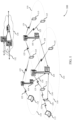
- FIG. 2 illustrates an example of a wireless communication system 200 that supports PUCCH reliability enhancements in accordance with aspects of the present disclosure.
- wireless communication system 200 may implement aspects of wireless communication system 100.
- wireless communication system 200 may include a base station 205 and a UE 210, which may be examples of the corresponding devices described herein.
- wireless communication system 200 may be a mmW network.
- base station 205 may perform beamformed transmissions to UE 210 using beam 215 and UE 210 may perform beamformed transmissions to base station 205 using one of beams 220 or 225.
- a beam may refer to a beamformed signal having an associated beam configuration.
- the beam configuration refers to a certain characteristic of the beam, such as beam direction, beam width, beam shape, QCL feature, and the like.
- the beam may refer to a transmit beam and/or a receive beam, or a beam association.
- base station 205 and UE 210 may perform beam management functions in order to maintain an active beam.
- the beam management functions may include base station 205 configuring UE 210 to transmit periodic CSI information, such as RSRP, RSRQ, CQI, error rate information, throughput level indications, and the like.
- the network uses the CSI information to configure resources for the UE 210, which may include assigning time and/or frequency resources, beam configurations, and the like.
- the UE 210 periodically transmits the CSI reports to base station 205 in a PUCCH signal, e.g., as often as is configured by the base station.
- PUCCH transmissions can also be triggered by base station 205 using a DCI signal.
- the PUCCH transmissions can also carry other valuable information, such as ACK/NACK information for PUSCH signals.
- base station 205 When scheduling resources for the PUCCH transmissions, base station 205 typically schedules UE 210 with multiple PUCCH resource sets, with each PUCCH resource set being associated with a particular UCI size. For each PUCCH resource set, base station 205 may schedule multiple PUCCH resources, with each PUCCH resource having a configured time resource, frequency resources, and one QCL (e.g., spatial relation information) indicating the beam to be used for the PUCCH transmission.
- the PUCCH transmission is DCI triggered
- the PUCCH resource for UE 210 to use is indicated in the DCI.
- the PUCCH transmission is for a periodic CSI reporting
- the PUCCH resource for UE 210 to use is indicated in the configuration for the periodic CSI reporting. Accordingly, UE 210 must typically use the beam that base station 205 indicates for the PUCCH transmission.
- the beam to be used for the PUCCH transmission may suddenly degrade to below an acceptable performance threshold.
- the beam may degrade due to blocking or fading, an available transmit power for the beam may be below a threshold (e.g., due to MPE limitations, limited transmit power due to other high priority transmissions in another carrier or cell group), and the like.
- these sudden changes in the communication metrics may not be known by the network (e.g., base station 205) and therefore, if UE 210 uses the configured beam for the PUCCH transmission, the PUCCH transmission may fail.
- a PUCCH transmission failure may mean that the beam management function, the ACK/NACK reporting function, and other critical network functions may fail.
- aspects of the described techniques improve the reliability of the PUCCH transmission to improve performance.
- the described techniques provide a mechanism where UE 210 can autonomously choose the best beam to use for the PUCCH transmission in order to ensure high reliability of the PUCCH signal. Aspects of the described techniques may consider network complexity and efficiency, power efficiency at the UE 210, and the like.
- the described techniques provide for the network to configure, for a PUCCH resource, two (or more) beams for UE 210 to use for the beamformed transmission of the PUCCH signal.
- the two (or more) beams may refer to the beam configuration, e.g., the QCL feature, of the beam for UE 210 to use.
- One of the configured QCL e.g., a first beam configuration
- a primary beam e.g., beam 220
- a second of the configured QCL may be considered a secondary or supplemental beam (e.g., beam 225).
- UE 210 may determine if there is a potential problem with performing the PUCCH transmission using the first beam configuration (e.g., beam 220). For example, UE 210 may determine whether a communication metric associated with using he first beam configuration has fallen below a threshold level. In some examples, this may include UE 210 determining that the RSRP, RSRQ, a SNR, a SINR, a throughput level, an error rate, and the like (e.g., a channel performance parameter), for the first beam configuration has fallen below an acceptable threshold level.
- this may include UE 210 determining that an available transmit power for the beamformed transmission of the PUCCH signal has fallen below an acceptable threshold level. This may be based on a MPE limit for the UE, based on the UE 210 performing other high-priority transmissions on different carriers or cell groups, and the like. Accordingly, the available transmit power may be the remaining transmit power available after UE 210 transmits the other signals.
- UE 210 may select the first beam configuration to use to perform the beamformed transmission of the PUCCH signal.
- the second beam configuration e.g., beam 225
- UE 210 may determine the performance (e.g., communication metric) of both the first beam configuration (e.g., beam 220) and the second beam configuration (e.g., beam 225) and select from the best performing beam configuration. For example, at the first PUCCH transmission occasion the UE 210 may determine the communication metric of the first and second beam configuration to determine which beam satisfies an acceptable threshold level, e.g., which beam configuration can provide the best performance for the beamformed transmission of the PUCCH signal. In the situation where neither beam configuration satisfies the threshold level, UE 210 may identify which beam configuration will perform best for the PUCCH transmission. Accordingly, UE 210 may choose between the better of the two beam configurations to use for the beamformed transmission of the PUCCH signal.
- an acceptable threshold level e.g., which beam configuration can provide the best performance for the beamformed transmission of the PUCCH signal.
- UE 210 may identify which beam configuration will perform best for the PUCCH transmission. Accordingly, UE 210
- UE 210 may select the second beam configuration to use for the beamformed transmission of the PUCCH signal at a second PUCCH transmission occasion.
- the second PUCCH transmission occasion may occur a time offset after the first PUCCH transmission occasion.
- the time offset can be configured by the network.
- the time offset may be configured as zero (0) such that UE 210 simply chooses the best performing beam configuration and uses it to transmit the PUCCH signal.
- the time offset may be configured as an absolute time offset, e.g., a fixed time that UE 210 waits after the first PUCCH transmission occasion before performing the PUCCH transmission using the second beam configuration.
- the time offset may be a relative time offset, e.g., a first uplink configured slot that occurs after the first PUCCH transmission occasion.
- the first and second beam configurations may also have different associated frequency resources.
- a PRB offset can be configured (e.g., as in the PUCCH resource configuration) to allow the second beam configuration (e.g., the supplemental beam) to use different frequency resources.
- the network may configure a supplementary PUCCH resource for one or multiple PUCCH resources.
- the supplementary PUCCH resource may be a frequency and/or time resource that is different from the primary resources.
- the QCL in the supplementary resource may differ from the QCL of any of its primary resource.
- the time offset may be defined for the supplementary resource.
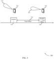
- FIG. 3 illustrates an example of a timing diagram 300 that supports PUCCH reliability enhancements in accordance with aspects of the present disclosure.
- timing diagram 300 may implement aspects of wireless communication systems 100/200. Aspects of timing diagram 300 may be implemented by a UE 305, which may be an example of the corresponding device described herein.
- timing diagram 300 illustrates aspects of a time offset 330.
- UE 305 may be configured with a beam 315 (e.g., a first beam configuration) and with a beam 325 (e.g., a second beam configuration). The beams may be configured for a beamformed transmission of a PUCCH signal.
- UE 305 may determine that a communication metric associated with using the first beam configuration (e.g., beam 315) fails to satisfy a threshold level.
- a channel performance parameter e.g., RSRP, RSRQ, CQI, SNR, etc.
- an available transmit power level may have degraded to an unacceptable performance level.
- UE 305 may select the second beam configuration (e.g., beam 325) to use to perform the beamformed transmission of the PUCCH signal at a second PUCCH transmission occasion 320.
- the second PUCCH transmission occasion may occur at a symbol t plus a time offset 330).
- the time offset 330 may refer to the time period between the first PUCCH transmission occasion 310 and the second PUCCH transmission occasion 320. Generally, the time offset 330 may refer to an absolute time or a relative time. The time offset 330 may refer to a positive integer. In some aspects, the time offset 330 may be configurable and can be zero (e.g., in the situation where the network is able to receive over the two beams simultaneously). In the example timing diagram 300, the time offset 330 is not configured as zero. In some aspects, the time offset 330 can be an element in a PUCCH resource configuration.
- the network may configure the time offset 330 large enough so that upon successful decoding of the PUCCH over the primary beam (e.g., beam 315), the frequency-time resource associated with the supplementary beam (e.g., beam 325) can be scheduled for other purposes.
- the transmit time of the supplementary beam may be the earliest time after symbol t plus the time offset 330 that is available for an uplink PUCCH transmission based on network configuration/signal, such as a slot format indicator (SFI).
- SFI slot format indicator
- FIG. 4 illustrates an example of a process 400 that supports PUCCH reliability enhancements in accordance with aspects of the present disclosure.
- process 400 may implement aspects of wireless communication systems 100/200 and/or timing diagram 300. Aspects of process 400 may be implemented by base station 405 and UE 410, which may be examples of the corresponding devices described herein.
- base station 405 may transmit (and UE 410 may receive) a signal that identifies a first beam configuration and a second beam configuration that are to be used to perform a beamformed transmission of a PUCCH signal.
- this may include UE 410 receiving a signal that configures a plurality of available PUCCH resources, with the plurality of available PUCCH resources including at least the first beam configuration and the second beam configuration.
- the first beam configuration may have an associated frequency resource that is different from the second beam configuration.
- the first beam configuration may have an associated QCL configuration that is different from a QCL configuration associated with the second beam configuration.
- the signal may be received in a DCI signal and/or a configuration signal.
- UE 410 may determine, at a first PUCCH transmission occasion that is associated with the first beam configuration, that a communication metric associated with performing the beamformed transmission of the PUCCH signal using the first beam configuration fails to satisfy a threshold. In some aspects, this may include UE 410 determining that a communication metric associated with a second beam configuration satisfies the threshold. UE 410 may then select the second beam configuration to use to perform the beamformed transmission of the PUCCH signal based on the determination that the second beam configuration satisfies the threshold.
- this determining at 420 may include UE 410 determining that a channel performance parameter associated with using the first beam configuration does not satisfy a threshold value.
- the communication metric may be based on the channel performance parameter.
- the channel performance parameter may include, but are not limited to, a RSRP, a RSRQ, a SNR, a SINR, and/or a throughput rate.
- this may include UE 410 determining that an available transmit power level is below a threshold value.
- UE 410 may be configured with an MPE limit, which may limit UE 410 from performing the PUCCH signal transmission using the first beam configuration.
- UE 410 may perform, at a second PUCCH transmission occasion and based at least in part on the determination that the first beam configuration fails to satisfy the threshold, the beamformed transmission of the PUCCH signal according to the second beam configuration.
- this may include UE 410 identifying a time offset value that is associated with the time difference between the first PUCCH transmission occasion and the second PUCCH transmission occasion.
- the time offset value may in include a zero value, a positive integer value, an absolute time, and/or relative time.
- this may include UE 410 identifying a first available PUCCH transmission occasion that occurs after the time offset value following the first PUCCH transmission occasion. Accordingly, the second PUCCH transmission occasion may be based on the first available PUCCH transmission occasion.
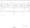
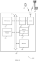
- FIG. 5 shows a block diagram 500 of a device 505 that supports PUCCH reliability enhancements in accordance with aspects of the present disclosure.
- the device 505 may be an example of aspects of a UE 115 as described herein.
- the device 505 may include a receiver 510, a communications manager 515, and a transmitter 520.
- the device 505 may also include a processor. Each of these components may be in communication with one another (e.g., via one or more buses).
- the receiver 510 may receive information such as packets, user data, or control information associated with various information channels (e.g., control channels, data channels, and information related to PUCCH reliability enhancements in mmW, etc.). Information may be passed on to other components of the device 505.
- the receiver 510 may be an example of aspects of the transceiver 820 described with reference to FIG. 8 .
- the receiver 510 may utilize a single antenna or a set of antennas.
- the communications manager 515 may receive a signal identifying a first beam configuration and a second beam configuration to be used for performing a beamformed transmission of a PUCCH signal, determine, at a first PUCCH transmission occasion associated with the first beam configuration, that a communication metric associated with performing the beamformed transmission of the PUCCH signal using the first beam configuration fails to satisfy a threshold, and perform, at a second PUCCH transmission occasion and based on the determining, the beamformed transmission of the PUCCH signal according to the second beam configuration.
- the communications manager 515 may be an example of aspects of the communications manager 810 described herein.
- the communications manager 515 may be implemented in hardware, code (e.g., software or firmware) executed by a processor, or any combination thereof. If implemented in code executed by a processor, the functions of the communications manager 515, or its sub-components may be executed by a general-purpose processor, a DSP, an application-specific integrated circuit (ASIC), a field-programmable gate array (FPGA) or other programmable logic device, discrete gate or transistor logic, discrete hardware components, or any combination thereof designed to perform the functions described in the present disclosure.
- code e.g., software or firmware
- ASIC application-specific integrated circuit
- FPGA field-programmable gate array
- the communications manager 515 may be physically located at various positions, including being distributed such that portions of functions are implemented at different physical locations by one or more physical components.
- the communications manager 515, or its sub-components may be a separate and distinct component in accordance with various aspects of the present disclosure.
- the communications manager 515, or its sub-components may be combined with one or more other hardware components, including but not limited to an input/output (I/O) component, a transceiver, a network server, another computing device, one or more other components described in the present disclosure, or a combination thereof in accordance with various aspects of the present disclosure.
- I/O input/output
- the transmitter 520 may transmit signals generated by other components of the device 505.
- the transmitter 520 may be collocated with a receiver 510 in a transceiver module.
- the transmitter 520 may be an example of aspects of the transceiver 820 described with reference to FIG. 8 .
- the transmitter 520 may utilize a single antenna or a set of antennas.
- FIG. 6 shows a block diagram 600 of a device 605 that supports PUCCH reliability enhancements in accordance with aspects of the present disclosure.
- the device 605 may be an example of aspects of a device 505 or a UE 115 as described herein.
- the device 605 may include a receiver 610, a communications manager 615, and a transmitter 635.
- the device 605 may also include a processor. Each of these components may be in communication with one another (e.g., via one or more buses).
- the receiver 610 may receive information such as packets, user data, or control information associated with various information channels (e.g., control channels, data channels, and information related to PUCCH reliability enhancements in mmW, etc.). Information may be passed on to other components of the device 605.
- the receiver 610 may be an example of aspects of the transceiver 820 described with reference to FIG. 8 .
- the receiver 610 may utilize a single antenna or a set of antennas.
- the communications manager 615 may be an example of aspects of the communications manager 515 as described herein.
- the communications manager 615 may include a configuration manager 620, a communication metric manager 625, and a PUCCH transmission manager 630.
- the communications manager 615 may be an example of aspects of the communications manager 810 described herein.
- the configuration manager 620 may receive a signal identifying a first beam configuration and a second beam configuration to be used for performing a beamformed transmission of a PUCCH signal.
- the communication metric manager 625 may determine, at a first PUCCH transmission occasion associated with the first beam configuration, that a communication metric associated with performing the beamformed transmission of the PUCCH signal using the first beam configuration fails to satisfy a threshold.
- the PUCCH transmission manager 630 may perform, at a second PUCCH transmission occasion and based on the determining, the beamformed transmission of the PUCCH signal according to the second beam configuration.
- the transmitter 635 may transmit signals generated by other components of the device 605.
- the transmitter 635 may be collocated with a receiver 610 in a transceiver module.
- the transmitter 635 may be an example of aspects of the transceiver 820 described with reference to FIG. 8 .
- the transmitter 635 may utilize a single antenna or a set of antennas.
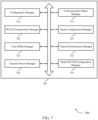
- FIG. 7 shows a block diagram 700 of a communications manager 705 that supports PUCCH reliability enhancements in accordance with aspects of the present disclosure.
- the communications manager 705 may be an example of aspects of a communications manager 515, a communications manager 615, or a communications manager 810 described herein.
- the communications manager 705 may include a configuration manager 710, a communication metric manager 715, a PUCCH transmission manager 720, a beam configuration manager 725, a time offset manager 730, a channel performance manager 735, a transmit power manager 740, and a multi-PUCCH configuration manager 745. Each of these modules may communicate, directly or indirectly, with one another (e.g., via one or more buses).
- the configuration manager 710 may receive a signal identifying a first beam configuration and a second beam configuration to be used for performing a beamformed transmission of a PUCCH signal.
- the second beam configuration includes a frequency resource that is different from the first beam configuration.
- the first beam configuration includes a first quasi-colocation (QCL) configuration that is different from a second QCL configuration of the second beam configuration.
- the signal is received in at least one of a downlink control indicator (DCI) signal, or a configuration signal, or a combination thereof.
- DCI downlink control indicator
- the communication metric manager 715 may determine, at a first PUCCH transmission occasion associated with the first beam configuration, that a communication metric associated with performing the beamformed transmission of the PUCCH signal using the first beam configuration fails to satisfy a threshold.
- the PUCCH transmission manager 720 may perform, at a second PUCCH transmission occasion and based on the determining, the beamformed transmission of the PUCCH signal according to the second beam configuration.
- the beam configuration manager 725 may determine that the communication metric associated with the second beam configuration satisfies the threshold. In some examples, the beam configuration manager 725 may select the second beam configuration to use to perform the beamformed transmission of the PUCCH signal based on the determining.
- the time offset manager 730 may identify, based on the signal, a time-offset value associated with a time difference between the first PUCCH transmission occasion and the second PUCCH transmission occasion. In some examples, the time offset manager 730 may identify a first available PUCCH transmission occasion that occurs after a time-offset value following the first PUCCH transmission occasion, where the second PUCCH transmission occasion is based on the first available PUCCH transmission occasion. In some cases, the time-offset value includes at least one of a zero value, or a positive integer value, or an absolute time, or a relative time.
- the channel performance manager 735 may determine that a channel performance parameter associated with using the first beam configuration does not satisfy a threshold value, where the communication metric is based on the channel performance parameter.
- the channel performance parameter includes at least one of a RSRP value, or a RSRQ value, or a SNR, or a SINR, or a throughput rate for the channel, or a combination thereof.
- the transmit power manager 740 may determine, based on a MPE limit, that an available transmit power level is below a threshold value, where the communication metric is based on the determining.
- the multi-PUCCH configuration manager 745 may receive the signal configuring a set of available PUCCH resources, where the set of available PUCCH resources include at least the first beam configuration and the second beam configuration.
- FIG. 8 shows a diagram of a system 800 including a device 805 that supports PUCCH reliability enhancements in accordance with aspects of the present disclosure.
- the device 805 may be an example of or include the components of device 505, device 605, or a UE 115 as described herein.
- the device 805 may include components for bi-directional voice and data communications including components for transmitting and receiving communications, including a communications manager 810, an I/O controller 815, a transceiver 820, an antenna 825, memory 830, and a processor 840. These components may be directly or indirectly coupled with each other, such as via one or more buses (e.g., bus 845).
- buses e.g., bus 845
- the communications manager 810 may receive a signal identifying a first beam configuration and a second beam configuration to be used for performing a beamformed transmission of a PUCCH signal, determine, at a first PUCCH transmission occasion associated with the first beam configuration, that a communication metric associated with performing the beamformed transmission of the PUCCH signal using the first beam configuration fails to satisfy a threshold, and perform, at a second PUCCH transmission occasion and based on the determining, the beamformed transmission of the PUCCH signal according to the second beam configuration.
- the I/O controller 815 may manage input and output signals for the device 805.
- the I/O controller 815 may also manage peripherals not integrated into the device 805.
- the I/O controller 815 may represent a physical connection or port to an external peripheral.
- the I/O controller 815 may utilize an operating system such as iOS ® , ANDROID ® , MS-DOS ® , MS-WINDOWS ® , OS/2 ® , UNIX ® , LINUX ® , or another known operating system.
- the I/O controller 815 may represent or interact with a modem, a keyboard, a mouse, a touchscreen, or a similar device.
- the I/O controller 815 may be implemented as part of a processor.
- a user may interact with the device 805 via the I/O controller 815 or via hardware components controlled by the I/O controller 815.
- the transceiver 820 may communicate bi-directionally, via one or more antennas, wired, or wireless links as described herein.
- the transceiver 820 may represent a wireless transceiver and may communicate bi-directionally with another wireless transceiver.
- the transceiver 820 may also include a modem to modulate the packets and provide the modulated packets to the antennas for transmission, and to demodulate packets received from the antennas.
- the wireless device may include a single antenna 825. However, in some cases the device may have more than one antenna 825, which may be capable of concurrently transmitting or receiving multiple wireless transmissions.
- the memory 830 may include random-access memory (RAM) and read-only memory (ROM).
- RAM random-access memory
- ROM read-only memory
- the memory 830 may store computer-readable, computer-executable code 835 including instructions that, when executed, cause the processor to perform various functions described herein.
- the memory 830 may contain, among other things, a BIOS which may control basic hardware or software operation such as the interaction with peripheral components or devices.
- the processor 840 may include an intelligent hardware device, (e.g., a general-purpose processor, a DSP, a CPU, a microcontroller, an ASIC, an FPGA, a programmable logic device, a discrete gate or transistor logic component, a discrete hardware component, or any combination thereof).
- the processor 840 may be configured to operate a memory array using a memory controller.
- a memory controller may be integrated into the processor 840.
- the processor 840 may be configured to execute computer-readable instructions stored in a memory (e.g., the memory 830) to cause the device 805 to perform various functions (e.g., functions or tasks supporting PUCCH reliability enhancements in mmW).
- the code 835 may include instructions to implement aspects of the present disclosure, including instructions to support wireless communications.
- the code 835 may be stored in a non-transitory computer-readable medium such as system memory or other type of memory.
- the code 835 may not be directly executable by the processor 840 but may cause a computer (e.g., when compiled and executed) to perform functions described herein.
- FIG. 9 shows a flowchart illustrating a method 900 that supports PUCCH reliability enhancements in accordance with aspects of the present disclosure.
- the operations of method 900 may be implemented by a UE 115 or its components as described herein.
- the operations of method 900 may be performed by a communications manager as described with reference to FIGs. 5 to 8 .
- a UE may execute a set of instructions to control the functional elements of the UE to perform the functions described herein Additionally or alternatively, a UE may perform aspects of the functions described herein using special-purpose hardware.
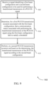
- the UE may receive a signal identifying a first beam configuration and a second beam configuration to be used for performing a beamformed transmission of a PUCCH signal.
- the operations of 905 may be performed according to the methods described herein. In some examples, aspects of the operations of 905 may be performed by a configuration manager as described with reference to FIGs. 5 to 8 .
- the UE may determine, at a first PUCCH transmission occasion associated with the first beam configuration, that a communication metric associated with performing the beamformed transmission of the PUCCH signal using the first beam configuration fails to satisfy a threshold.
- the operations of 910 may be performed according to the methods described herein. In some examples, aspects of the operations of 910 may be performed by a communication metric manager as described with reference to FIGs. 5 to 8 .
- the UE may perform, at a second PUCCH transmission occasion and based on the determining, the beamformed transmission of the PUCCH signal according to the second beam configuration.
- the operations of 915 may be performed according to the methods described herein. In some examples, aspects of the operations of 915 may be performed by a PUCCH transmission manager as described with reference to FIGs. 5 to 8 .
- FIG. 10 shows a flowchart illustrating a method 1000 that supports PUCCH reliability enhancements in accordance with aspects of the present disclosure.
- the operations of method 1000 may be implemented by a UE 115 or its components as described herein.
- the operations of method 1000 may be performed by a communications manager as described with reference to FIGs. 5 to 8 .
- a UE may execute a set of instructions to control the functional elements of the UE to perform the functions described herein.
- a UE may perform aspects of the functions described herein using special-purpose hardware.
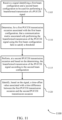
- the UE may receive a signal identifying a first beam configuration and a second beam configuration to be used for performing a beamformed transmission of a PUCCH signal.
- the operations of 1005 may be performed according to the methods described herein. In some examples, aspects of the operations of 1005 may be performed by a configuration manager as described with reference to FIGs. 5 to 8 .
- the UE may determine, at a first PUCCH transmission occasion associated with the first beam configuration, that a communication metric associated with performing the beamformed transmission of the PUCCH signal using the first beam configuration fails to satisfy a threshold.
- the operations of 1010 may be performed according to the methods described herein. In some examples, aspects of the operations of 1010 may be performed by a communication metric manager as described with reference to FIGs. 5 to 8 .
- the UE may perform, at a second PUCCH transmission occasion and based on the determining, the beamformed transmission of the PUCCH signal according to the second beam configuration.
- the operations of 1015 may be performed according to the methods described herein. In some examples, aspects of the operations of 1015 may be performed by a PUCCH transmission manager as described with reference to FIGs. 5 to 8 .
- the UE may determine that the communication metric associated with the second beam configuration satisfies the threshold.
- the operations of 1020 may be performed according to the methods described herein. In some examples, aspects of the operations of 1020 may be performed by a beam configuration manager as described with reference to FIGs. 5 to 8 .
- the UE may select the second beam configuration to use to perform the beamformed transmission of the PUCCH signal based on the determining at 1020.
- the operations of 1025 may be performed according to the methods described herein. In some examples, aspects of the operations of 1025 may be performed by a beam configuration manager as described with reference to FIGs. 5 to 8 .
- FIG. 11 shows a flowchart illustrating a method 1100 that supports PUCCH reliability enhancements in accordance with aspects of the present disclosure.
- the operations of method 1100 may be implemented by a UE 115 or its components as described herein.
- the operations of method 1100 may be performed by a communications manager as described with reference to FIGs. 5 to 8 .
- a UE may execute a set of instructions to control the functional elements of the UE to perform the functions described herein.
- a UE may perform aspects of the functions described herein using special-purpose hardware.
- the UE may receive a signal identifying a first beam configuration and a second beam configuration to be used for performing a beamformed transmission of a PUCCH signal.
- the operations of 1105 may be performed according to the methods described herein. In some examples, aspects of the operations of 1105 may be performed by a configuration manager as described with reference to FIGs. 5 to 8 .
- the UE may determine, at a first PUCCH transmission occasion associated with the first beam configuration, that a communication metric associated with performing the beamformed transmission of the PUCCH signal using the first beam configuration fails to satisfy a threshold.
- the operations of 1110 may be performed according to the methods described herein. In some examples, aspects of the operations of 1110 may be performed by a communication metric manager as described with reference to FIGs. 5 to 8 .
- the UE may perform, at a second PUCCH transmission occasion and based on the determining, the beamformed transmission of the PUCCH signal according to the second beam configuration.
- the operations of 1115 may be performed according to the methods described herein. In some examples, aspects of the operations of 1115 may be performed by a PUCCH transmission manager as described with reference to FIGs. 5 to 8 .
- the UE may identify, based on the signal, a time-offset value associated with a time difference between the first PUCCH transmission occasion and the second PUCCH transmission occasion.
- the operations of 1120 may be performed according to the methods described herein. In some examples, aspects of the operations of 1120 may be performed by a time offset manager as described with reference to FIGs. 5 to 8 .
- CDMA code division multiple access
- TDMA time division multiple access
- FDMA frequency division multiple access
- OFDMA orthogonal frequency division multiple access
- SC-FDMA single carrier frequency division multiple access
- a CDMA system may implement a radio technology such as CDMA2000, Universal Terrestrial Radio Access (UTRA), etc.
- CDMA2000 covers IS-2000, IS-95, and IS-856 standards.
- IS-2000 Releases may be commonly referred to as CDMA2000 1X, 1X, etc.
- IS-856 TIA-856) is commonly referred to as CDMA2000 1xEV-DO, High Rate Packet Data (HRPD), etc.
- UTRA includes Wideband CDMA (WCDMA) and other variants of CDMA.
- a TDMA system may implement a radio technology such as Global System for Mobile Communications (GSM).
- GSM Global System for Mobile Communications
- An OFDMA system may implement a radio technology such as Ultra Mobile Broadband (UMB), Evolved UTRA (E-UTRA), Institute of Electrical and Electronics Engineers (IEEE) 802.11 (Wi-Fi), IEEE 802.16 (WiMAX), IEEE 802.20, Flash-OFDM, etc.
- UMB Ultra Mobile Broadband
- E-UTRA Evolved UTRA
- IEEE Institute of Electrical and Electronics Engineers
- Wi-Fi Wi-Fi
- WiMAX IEEE 802.16
- IEEE 802.20 Flash-OFDM
- UTRA and E-UTRA are part of Universal Mobile Telecommunications System (UMTS).
- LTE, LTE-A, and LTE-A Pro are releases of UMTS that use E-UTRA.
- UTRA, E-UTRA, UMTS, LTE, LTE-A, LTE-A Pro, NR, and GSM are described in documents from the organization named "3rd Generation Partnership Project" (3GPP).
- CDMA2000 and UMB are described in documents from an organization named "3rd Generation Partnership Project 2" (3GPP2).
- 3GPP2 3rd Generation Partnership Project 2
- the techniques described herein may be used for the systems and radio technologies mentioned above as well as other systems and radio technologies. While aspects of an LTE, LTE-A, LTE-A Pro, or NR system may be described for purposes of example, and LTE, LTE-A, LTE-A Pro, or NR terminology may be used in much of the description, the techniques described herein are applicable beyond LTE, LTE-A, LTE-A Pro, or NR applications.
- a macro cell generally covers a relatively large geographic area (e.g., several kilometers in radius) and may allow unrestricted access by UEs 115 with service subscriptions with the network provider.
- a small cell may be associated with a lower-powered base station 105, as compared with a macro cell, and a small cell may operate in the same or different (e.g., licensed, unlicensed, etc.) frequency bands as macro cells.
- Small cells may include pico cells, femto cells, and micro cells according to various examples.
- a pico cell for example, may cover a small geographic area and may allow unrestricted access by UEs 115 with service subscriptions with the network provider.
- a femto cell may also cover a small geographic area (e.g., a home) and may provide restricted access by UEs 115 having an association with the femto cell (e.g., UEs 115 in a closed subscriber group (CSG), UEs 115 for users in the home, and the like).
- An eNB for a macro cell may be referred to as a macro eNB.
- An eNB for a small cell may be referred to as a small cell eNB, a pico eNB, a femto eNB, or a home eNB.
- An eNB may support one or multiple (e.g., two, three, four, and the like) cells, and may also support communications using one or multiple component carriers.
- the wireless communications system 100 or systems described herein may support synchronous or asynchronous operation.
- the base stations 105 may have similar frame timing, and transmissions from different base stations 105 may be approximately aligned in time.
- the base stations 105 may have different frame timing, and transmissions from different base stations 105 may not be aligned in time.
- the techniques described herein may be used for either synchronous or asynchronous operations.
- Information and signals described herein may be represented using any of a variety of different technologies and techniques.
- data, instructions, commands, information, signals, bits, symbols, and chips that may be referenced throughout the above description may be represented by voltages, currents, electromagnetic waves, magnetic fields or particles, optical fields or particles, or any combination thereof.
- DSP digital signal processor
- ASIC application-specific integrated circuit
- FPGA field-programmable gate array
- PLD programmable logic device
- a general-purpose processor may be a microprocessor, but in the alternative, the processor may be any conventional processor, controller, microcontroller, or state machine.
- a processor may also be implemented as a combination of computing devices (e.g., a combination of a DSP and a microprocessor, multiple microprocessors, one or more microprocessors in conjunction with a DSP core, or any other such configuration).
- the functions described herein may be implemented in hardware, software executed by a processor, firmware, or any combination thereof. If implemented in software executed by a processor, the functions may be stored on or transmitted over as one or more instructions or code on a computer-readable medium. Other examples and implementations are within the scope of the disclosure and appended claims. For example, due to the nature of software, functions described herein can be implemented using software executed by a processor, hardware, firmware, hardwiring, or combinations of any of these. Features implementing functions may also be physically located at various positions, including being distributed such that portions of functions are implemented at different physical locations.
- Computer-readable media includes both non-transitory computer storage media and communication media including any medium that facilitates transfer of a computer program from one place to another.
- a non-transitory storage medium may be any available medium that can be accessed by a general purpose or special purpose computer.
- non-transitory computer-readable media may include random-access memory (RAM), read-only memory (ROM), electrically erasable programmable read only memory (EEPROM), flash memory, compact disk (CD) ROM or other optical disk storage, magnetic disk storage or other magnetic storage devices, or any other non-transitory medium that can be used to carry or store desired program code means in the form of instructions or data structures and that can be accessed by a general-purpose or special-purpose computer, or a general-purpose or special-purpose processor.
- RAM random-access memory
- ROM read-only memory
- EEPROM electrically erasable programmable read only memory
- CD compact disk
- magnetic disk storage or other magnetic storage devices or any other non-transitory medium that can be used to carry
- any connection is properly termed a computer-readable medium.
- the software is transmitted from a website, server, or other remote source using a coaxial cable, fiber optic cable, twisted pair, digital subscriber line (DSL), or wireless technologies such as infrared, radio, and microwave
- the coaxial cable, fiber optic cable, twisted pair, DSL, or wireless technologies such as infrared, radio, and microwave are included in the definition of medium.
- Disk and disc include CD, laser disc, optical disc, digital versatile disc (DVD), floppy disk and Blu-ray disc where disks usually reproduce data magnetically, while discs reproduce data optically with lasers. Combinations of the above are also included within the scope of computer-readable media.
Landscapes
- Engineering & Computer Science (AREA)
- Computer Networks & Wireless Communication (AREA)
- Signal Processing (AREA)
- Quality & Reliability (AREA)
- Physics & Mathematics (AREA)
- Electromagnetism (AREA)
- Mobile Radio Communication Systems (AREA)
Claims (13)
- Verfahren (900) zur drahtlosen Kommunikation bei einem Benutzergerät, UE (210), umfassend:Empfangen (905) eines Signals, das eine erste Beam-Konfiguration (220) und eine zweite Beam-Konfiguration (225) identifiziert, die zu verwenden sind, um eine Übertragung eines Physical Uplink Control Channel-, PUCCH-, Signals mit Beamforming auszuführen, wobei sich eine Beam-Konfiguration auf eine Charakteristik des jeweiligen Beams bezieht, die eine Beam-Richtung, eine Beam-Breite, eine Beam-Form und/oder ein Quasi-Colocation-, QCL-, Merkmal enthält;Auswählen der ersten Beam-Konfiguration (220) als eine primäre Konfiguration, die zu verwenden ist, um die Übertragung mit Beamforming auszuführen;Bestimmen (910) für eine erste PUCCH-Übertragungsgelegenheit, die der ersten Beam-Konfiguration (220) zugeordnet ist, dass ein Leistungsniveau, das dem Ausführen der Übertragung mit Beamforming des PUCCH-Signals unter Verwendung der ersten Beam-Konfiguration (220) zugeordnet ist, einen Schwellenwert nicht erfüllt;autonomes Auswählen der zweiten Beam-Konfiguration (225), die zu verwenden ist, um die PUCCH-Signalübertragung auszuführen;Identifizieren einer ersten verfügbaren PUCCH-Übertragungsgelegenheit, die nach einem Zeitversatzwert auftritt, der auf die erste PUCCH-Übertragungsgelegenheit folgt, wobei eine zweite PUCCH-Übertragungsgelegenheit auf der ersten verfügbaren PUCCH-Übertragungsgelegenheit basiert; undAusführen (915) bei der zweiten PUCCH-Übertragungsgelegenheit der Übertragung mit Beamforming des PUCCH-Signals gemäß der ausgewählten zweiten Beam-Konfiguration (225).
- Verfahren (900) gemäß Anspruch 1, weiterhin umfassend:Bestimmen, dass das Leistungsniveau, das der zweiten Beam-Konfiguration zugeordnet ist, den Schwellenwert erfüllt; undAuswählen der zweiten Beam-Konfiguration (225), die zu verwenden ist, um die Übertragung mit Beamforming des PUCCH-Signals auszuführen, basierend zumindest teilweise auf dem Bestimmen, dass das Leistungsniveau, das der zweiten Beam-Konfiguration (225) zugeordnet ist, den Schwellenwert erfüllt.
- Verfahren (900) gemäß Anspruch 1, weiterhin umfassend:
Identifizieren, basierend zumindest teilweise auf dem Signal, des Zeitversatzwerts (330), der einer Zeitdifferenz zwischen der ersten PUCCH-Übertragungsgelegenheit und der zweiten PUCCH-Übertragungsgelegenheit zugeordnet ist. - Verfahren (900) gemäß Anspruch 3, wobei der Zeitversatzwert zumindest einen von einem Nullwert oder einem positiven ganzzahligen Wert oder einer absoluten Zeit oder einer relativen Zeit umfasst.
- Verfahren (900) gemäß Anspruch 1, wobei das Bestimmen für die erste PUCCH-Übertragungsgelegenheit, die der ersten Beam-Konfiguration zugeordnet ist, dass das Leistungsniveau, das dem Ausführen der Übertragung mit Beamforming des PUCCH-Signals unter Verwendung der ersten Beam-Konfiguration zugeordnet ist, den Schwellenwert nicht erfüllt, umfasst:
Bestimmen, dass ein Wert für einen Kanalleistungsparameter, der dem Verwenden der ersten Beam-Konfiguration zugeordnet ist, den Schwellenwert nicht erfüllt, wobei das Leistungsniveau zumindest teilweise auf dem Kanalleistungsparameter basiert. - Verfahren (900) gemäß Anspruch 5, wobei der Wert für den Kanalleistungsparameter zumindest einen von einem Referenzsignalempfangsleistungs-, RSRP-Wert, oder einem Referenzsignalempfangsqualitäts-, RSRQ-Wert, oder einem Signal-zu-RauschVerhältnis, SNR, oder einem Signal-zu-Rausch-plus-Interferenz-, SINR, oder einer Durchsatzrate für einen Kanal oder einer Kombination davon umfasst.
- Verfahren (900) gemäß Anspruch 1, wobei das Bestimmen für die erste PUCCH-Übertragungsgelegenheit, die der ersten Beam-Konfiguration zugeordnet ist, dass das Leistungsniveau, das dem Ausführen der Übertragung mit Beamforming des PUCCH-Signals unter Verwendung der ersten Beam-Konfiguration zugeordnet ist, den Schwellenwert nicht erfüllt, umfasst:
Bestimmen, basierend zumindest teilweise auf einer maximal zulässigen Expositions-, MPE-, Grenze, dass ein verfügbares Übertragungsleistungsniveau unter einem Wert liegt, der dem Schwellenwert zugeordnet ist, wobei das Leistungsniveau zumindest teilweise auf dem Bestimmen basiert, dass das verfügbare Übertragungsleistungsniveau unter dem Wert liegt. - Verfahren (900) gemäß Anspruch 1, weiterhin umfassend:
Empfangen des Signals, das eine Vielzahl von verfügbaren PUCCH-Ressourcen konfiguriert, wobei die Vielzahl von verfügbaren PUCCH-Ressourcen Zuordnungen zu zumindest der ersten Beam-Konfiguration und der zweiten Beam-Konfiguration umfasst. - Verfahren gemäß Anspruch 1, wobei die zweite Beam-Konfiguration eine Frequenzressource umfasst, die sich von einer Frequenzressource der ersten Beam-Konfiguration unterscheidet.
- Verfahren (900) gemäß Anspruch 1, wobei die erste Beam-Konfiguration eine erste Quasi-Colocation-, QCL-, Konfiguration umfasst, die sich von einer zweiten QCL-Konfiguration der zweiten Beam-Konfiguration unterscheidet.
- Verfahren (900) gemäß Anspruch 1, wobei das Signal in zumindest einem von einem Downlink-Kontrollindikator-, DCI-, Signal oder einem Konfigurationssignal oder einer Kombination davon empfangen wird.
- Vorrichtung (505, 605, 705, 805) zur drahtlosen Kommunikation, umfassend Mittel, die zum Ausführen des Verfahrens gemäß einem der Ansprüche 1 bis 11 konfiguriert sind.
- Computerprogramm, umfassend Programmanweisungen, die, wenn sie von einem Computer ausgeführt werden, den Computer veranlassen, alle Schritte des Verfahrens gemäß einem der Ansprüche 1 bis 11 zu implementieren.
Applications Claiming Priority (3)
| Application Number | Priority Date | Filing Date | Title |
|---|---|---|---|
| US201862655606P | 2018-04-10 | 2018-04-10 | |
| US16/378,099 US10959232B2 (en) | 2018-04-10 | 2019-04-08 | Physical uplink control channel reliability enhancements |
| PCT/US2019/026625 WO2019199858A1 (en) | 2018-04-10 | 2019-04-09 | Physical uplink control channel reliability enhancements |
Publications (2)
| Publication Number | Publication Date |
|---|---|
| EP3776906A1 EP3776906A1 (de) | 2021-02-17 |
| EP3776906B1 true EP3776906B1 (de) | 2024-12-11 |
Family
ID=68096636
Family Applications (1)
| Application Number | Title | Priority Date | Filing Date |
|---|---|---|---|
| EP19721435.6A Active EP3776906B1 (de) | 2018-04-10 | 2019-04-09 | Zuverlässigkeitsverbesserung bei einem physikalischen uplink-steuerkanal |
Country Status (4)
| Country | Link |
|---|---|
| US (1) | US10959232B2 (de) |
| EP (1) | EP3776906B1 (de) |
| CN (1) | CN111937322B (de) |
| WO (1) | WO2019199858A1 (de) |
Families Citing this family (15)
| Publication number | Priority date | Publication date | Assignee | Title |
|---|---|---|---|---|
| KR102712368B1 (ko) * | 2018-05-24 | 2024-10-04 | 삼성전자 주식회사 | 상향링크 제어 신호를 송수신하는 방법 및 이를 구현한 장치 |
| US11569886B2 (en) | 2019-04-01 | 2023-01-31 | Qualcomm Incorporated | Network-sensitive transmit diversity scheme |
| US12273905B2 (en) * | 2019-07-05 | 2025-04-08 | Qualcomm Incorporated | Dynamically activated channel measurement resources for cross-carrier scheduling |
| US11438052B2 (en) * | 2019-11-27 | 2022-09-06 | Qualcomm Incorporated | Joint transmit and receive beam-sweeping for sidelink |
| CN113141655B (zh) | 2020-01-19 | 2022-08-19 | 华为技术有限公司 | 一种波束选择方法及通信装置 |
| CN115280681B (zh) * | 2020-02-11 | 2023-07-28 | 高通股份有限公司 | 用于确定波束度量以用于最大准许照射报告的技术 |
| US12256442B2 (en) * | 2020-02-11 | 2025-03-18 | Qualcomm Incorporated | Techniques for requesting uplink transmission resources for maximum permissible exposure reporting |
| CN113286366B (zh) * | 2020-02-20 | 2023-03-10 | 上海华为技术有限公司 | 波束管理方法,波束管理系统以及相关设备 |
| WO2021168655A1 (en) * | 2020-02-25 | 2021-09-02 | Qualcomm Incorporated | Techniques for modifying uplink communications to avoid maximum permissible exposure (mpe) in wireless communications |
| WO2021168642A1 (en) * | 2020-02-25 | 2021-09-02 | Qualcomm Incorporated | Techniques for detecting maximum permissible exposure (mpe) events in wireless communications |
| US11683792B2 (en) | 2020-04-17 | 2023-06-20 | Qualcomm Incorporated | Resource reselection trigger with beamforming |
| US11659539B2 (en) * | 2020-06-26 | 2023-05-23 | Samsung Electronics Co., Ltd. | Method and apparatus for event-based uplink transmit beam switch |
| US11800389B2 (en) * | 2020-06-29 | 2023-10-24 | Qualcomm Incorporated | Techniques for beamforming enhancement and feedback |
| US12349197B2 (en) * | 2021-03-17 | 2025-07-01 | Qualcomm Incorporated | Increasing random access coverage |
| CN116456360A (zh) * | 2022-01-07 | 2023-07-18 | 北京三星通信技术研究有限公司 | 一种增强上行信号发送方法和设备 |
Family Cites Families (4)
| Publication number | Priority date | Publication date | Assignee | Title |
|---|---|---|---|---|
| KR101881847B1 (ko) * | 2012-02-21 | 2018-08-24 | 삼성전자주식회사 | 통신 시스템에서 신호를 송수신하는 방법 및 장치 |
| US10631331B2 (en) * | 2016-04-22 | 2020-04-21 | Qualcomm Incorporated | Frame structure signaling for multefire |
| WO2017190356A1 (en) * | 2016-05-06 | 2017-11-09 | Qualcomm Incorporated | Enhancement of linear combination codebooks in fd-mimo |
| US10425139B2 (en) * | 2016-09-21 | 2019-09-24 | Samsung Electronics Co., Ltd. | Method and apparatus for beam management reference signals in wireless communication systems |
-
2019
- 2019-04-08 US US16/378,099 patent/US10959232B2/en active Active
- 2019-04-09 WO PCT/US2019/026625 patent/WO2019199858A1/en not_active Ceased
- 2019-04-09 EP EP19721435.6A patent/EP3776906B1/de active Active
- 2019-04-09 CN CN201980023504.6A patent/CN111937322B/zh active Active
Non-Patent Citations (2)
| Title |
|---|
| ERICSSON: "Remaining details of beam recovery", vol. RAN WG1, no. Reno, USA; 20171127 - 20171201, 18 November 2017 (2017-11-18), XP051370194, Retrieved from the Internet <URL:http://www.3gpp.org/ftp/tsg%5Fran/WG1%5FRL1/TSGR1%5F91/Docs/> [retrieved on 20171118] * |
| SONY: "Fallback beam and RLF", vol. RAN WG2, no. Spokane, USA; 20170403 - 20170407, 3 April 2017 (2017-04-03), XP051245167, Retrieved from the Internet <URL:http://www.3gpp.org/ftp/Meetings_3GPP_SYNC/RAN2/Docs/> [retrieved on 20170403] * |
Also Published As
| Publication number | Publication date |
|---|---|
| WO2019199858A1 (en) | 2019-10-17 |
| EP3776906A1 (de) | 2021-02-17 |
| US10959232B2 (en) | 2021-03-23 |
| CN111937322A (zh) | 2020-11-13 |
| US20190313393A1 (en) | 2019-10-10 |
| CN111937322B (zh) | 2023-09-08 |
Similar Documents
| Publication | Publication Date | Title |
|---|---|---|
| EP3776906B1 (de) | Zuverlässigkeitsverbesserung bei einem physikalischen uplink-steuerkanal | |
| EP3707827B1 (de) | Duplex-modi auf der grundlage von strahlkonfigurationen für drahtlose kommunikation | |
| US11950113B2 (en) | Prioritizations during beam failure recovery | |
| EP3804185B1 (de) | Bestätigungsentwurf für mehrfachübertragungskonfigurationsindikatorzustandsübertragung | |
| US11109380B2 (en) | Uplink control channel beam switch procedure | |
| US11109236B2 (en) | Techniques for carrier feedback in wireless systems | |
| US12284613B2 (en) | Communication configuration for high pathloss operations | |
| US11463228B2 (en) | Duplexing modes based on power configurations for transmissions | |
| US11252706B2 (en) | Uplink control channel codebook design in new radio unlicensed | |
| US11039465B2 (en) | Uplink control information piggybacking in wireless systems | |
| WO2019158080A1 (en) | Techniques for activating or deactivating semi-persistent configuration for channel state indicator resource sets | |
| EP3874842B1 (de) | Durchsatzmodifizierung für zeitverzögerte träger | |
| US20210014898A1 (en) | Transmitting uplink control information in a two-step random access procedure | |
| US11166274B2 (en) | User equipment-specific hybrid automatic repeat request timeline offset |
Legal Events
| Date | Code | Title | Description |
|---|---|---|---|
| STAA | Information on the status of an ep patent application or granted ep patent |
Free format text: STATUS: UNKNOWN |
|
| STAA | Information on the status of an ep patent application or granted ep patent |
Free format text: STATUS: THE INTERNATIONAL PUBLICATION HAS BEEN MADE |
|
| PUAI | Public reference made under article 153(3) epc to a published international application that has entered the european phase |
Free format text: ORIGINAL CODE: 0009012 |
|
| STAA | Information on the status of an ep patent application or granted ep patent |
Free format text: STATUS: REQUEST FOR EXAMINATION WAS MADE |
|
| 17P | Request for examination filed |
Effective date: 20200922 |
|
| AK | Designated contracting states |
Kind code of ref document: A1 Designated state(s): AL AT BE BG CH CY CZ DE DK EE ES FI FR GB GR HR HU IE IS IT LI LT LU LV MC MK MT NL NO PL PT RO RS SE SI SK SM TR |
|
| AX | Request for extension of the european patent |
Extension state: BA ME |
|
| DAV | Request for validation of the european patent (deleted) | ||
| DAX | Request for extension of the european patent (deleted) | ||
| STAA | Information on the status of an ep patent application or granted ep patent |
Free format text: STATUS: EXAMINATION IS IN PROGRESS |
|
| 17Q | First examination report despatched |
Effective date: 20221208 |
|
| GRAP | Despatch of communication of intention to grant a patent |
Free format text: ORIGINAL CODE: EPIDOSNIGR1 |
|
| STAA | Information on the status of an ep patent application or granted ep patent |
Free format text: STATUS: GRANT OF PATENT IS INTENDED |
|
| INTG | Intention to grant announced |
Effective date: 20240715 |
|
| GRAS | Grant fee paid |
Free format text: ORIGINAL CODE: EPIDOSNIGR3 |
|
| GRAA | (expected) grant |
Free format text: ORIGINAL CODE: 0009210 |
|
| STAA | Information on the status of an ep patent application or granted ep patent |
Free format text: STATUS: THE PATENT HAS BEEN GRANTED |
|
| AK | Designated contracting states |
Kind code of ref document: B1 Designated state(s): AL AT BE BG CH CY CZ DE DK EE ES FI FR GB GR HR HU IE IS IT LI LT LU LV MC MK MT NL NO PL PT RO RS SE SI SK SM TR |
|
| REG | Reference to a national code |
Ref country code: GB Ref legal event code: FG4D |
|
| REG | Reference to a national code |
Ref country code: CH Ref legal event code: EP |
|
| REG | Reference to a national code |
Ref country code: IE Ref legal event code: FG4D |
|
| REG | Reference to a national code |
Ref country code: DE Ref legal event code: R096 Ref document number: 602019063340 Country of ref document: DE |
|
| REG | Reference to a national code |
Ref country code: LT Ref legal event code: MG9D |
|
| PG25 | Lapsed in a contracting state [announced via postgrant information from national office to epo] |
Ref country code: HR Free format text: LAPSE BECAUSE OF FAILURE TO SUBMIT A TRANSLATION OF THE DESCRIPTION OR TO PAY THE FEE WITHIN THE PRESCRIBED TIME-LIMIT Effective date: 20241211 |
|
| PG25 | Lapsed in a contracting state [announced via postgrant information from national office to epo] |
Ref country code: FI Free format text: LAPSE BECAUSE OF FAILURE TO SUBMIT A TRANSLATION OF THE DESCRIPTION OR TO PAY THE FEE WITHIN THE PRESCRIBED TIME-LIMIT Effective date: 20241211 |
|
| PG25 | Lapsed in a contracting state [announced via postgrant information from national office to epo] |
Ref country code: BG Free format text: LAPSE BECAUSE OF FAILURE TO SUBMIT A TRANSLATION OF THE DESCRIPTION OR TO PAY THE FEE WITHIN THE PRESCRIBED TIME-LIMIT Effective date: 20241211 |
|
| REG | Reference to a national code |
Ref country code: NL Ref legal event code: MP Effective date: 20241211 |
|
| PG25 | Lapsed in a contracting state [announced via postgrant information from national office to epo] |
Ref country code: ES Free format text: LAPSE BECAUSE OF FAILURE TO SUBMIT A TRANSLATION OF THE DESCRIPTION OR TO PAY THE FEE WITHIN THE PRESCRIBED TIME-LIMIT Effective date: 20241211 |
|
| PG25 | Lapsed in a contracting state [announced via postgrant information from national office to epo] |
Ref country code: NO Free format text: LAPSE BECAUSE OF FAILURE TO SUBMIT A TRANSLATION OF THE DESCRIPTION OR TO PAY THE FEE WITHIN THE PRESCRIBED TIME-LIMIT Effective date: 20250311 |
|
| PG25 | Lapsed in a contracting state [announced via postgrant information from national office to epo] |
Ref country code: GR Free format text: LAPSE BECAUSE OF FAILURE TO SUBMIT A TRANSLATION OF THE DESCRIPTION OR TO PAY THE FEE WITHIN THE PRESCRIBED TIME-LIMIT Effective date: 20250312 Ref country code: LV Free format text: LAPSE BECAUSE OF FAILURE TO SUBMIT A TRANSLATION OF THE DESCRIPTION OR TO PAY THE FEE WITHIN THE PRESCRIBED TIME-LIMIT Effective date: 20241211 |
|
| PGFP | Annual fee paid to national office [announced via postgrant information from national office to epo] |
Ref country code: FR Payment date: 20250319 Year of fee payment: 7 |
|
| PGFP | Annual fee paid to national office [announced via postgrant information from national office to epo] |
Ref country code: GB Payment date: 20250313 Year of fee payment: 7 |
|
| PG25 | Lapsed in a contracting state [announced via postgrant information from national office to epo] |
Ref country code: RS Free format text: LAPSE BECAUSE OF FAILURE TO SUBMIT A TRANSLATION OF THE DESCRIPTION OR TO PAY THE FEE WITHIN THE PRESCRIBED TIME-LIMIT Effective date: 20250311 |
|
| PG25 | Lapsed in a contracting state [announced via postgrant information from national office to epo] |
Ref country code: NL Free format text: LAPSE BECAUSE OF FAILURE TO SUBMIT A TRANSLATION OF THE DESCRIPTION OR TO PAY THE FEE WITHIN THE PRESCRIBED TIME-LIMIT Effective date: 20241211 |
|
| REG | Reference to a national code |
Ref country code: AT Ref legal event code: MK05 Ref document number: 1751180 Country of ref document: AT Kind code of ref document: T Effective date: 20241211 |
|
| PG25 | Lapsed in a contracting state [announced via postgrant information from national office to epo] |
Ref country code: SM Free format text: LAPSE BECAUSE OF FAILURE TO SUBMIT A TRANSLATION OF THE DESCRIPTION OR TO PAY THE FEE WITHIN THE PRESCRIBED TIME-LIMIT Effective date: 20241211 |
|
| PG25 | Lapsed in a contracting state [announced via postgrant information from national office to epo] |
Ref country code: PL Free format text: LAPSE BECAUSE OF FAILURE TO SUBMIT A TRANSLATION OF THE DESCRIPTION OR TO PAY THE FEE WITHIN THE PRESCRIBED TIME-LIMIT Effective date: 20241211 |
|
| PGFP | Annual fee paid to national office [announced via postgrant information from national office to epo] |
Ref country code: DE Payment date: 20250317 Year of fee payment: 7 |
|
| PG25 | Lapsed in a contracting state [announced via postgrant information from national office to epo] |
Ref country code: IS Free format text: LAPSE BECAUSE OF FAILURE TO SUBMIT A TRANSLATION OF THE DESCRIPTION OR TO PAY THE FEE WITHIN THE PRESCRIBED TIME-LIMIT Effective date: 20250411 |
|
| PG25 | Lapsed in a contracting state [announced via postgrant information from national office to epo] |
Ref country code: PT Free format text: LAPSE BECAUSE OF FAILURE TO SUBMIT A TRANSLATION OF THE DESCRIPTION OR TO PAY THE FEE WITHIN THE PRESCRIBED TIME-LIMIT Effective date: 20250411 |
|
| PG25 | Lapsed in a contracting state [announced via postgrant information from national office to epo] |
Ref country code: EE Free format text: LAPSE BECAUSE OF FAILURE TO SUBMIT A TRANSLATION OF THE DESCRIPTION OR TO PAY THE FEE WITHIN THE PRESCRIBED TIME-LIMIT Effective date: 20241211 |
|
| PG25 | Lapsed in a contracting state [announced via postgrant information from national office to epo] |
Ref country code: RO Free format text: LAPSE BECAUSE OF FAILURE TO SUBMIT A TRANSLATION OF THE DESCRIPTION OR TO PAY THE FEE WITHIN THE PRESCRIBED TIME-LIMIT Effective date: 20241211 Ref country code: AT Free format text: LAPSE BECAUSE OF FAILURE TO SUBMIT A TRANSLATION OF THE DESCRIPTION OR TO PAY THE FEE WITHIN THE PRESCRIBED TIME-LIMIT Effective date: 20241211 |
|
| PG25 | Lapsed in a contracting state [announced via postgrant information from national office to epo] |
Ref country code: SK Free format text: LAPSE BECAUSE OF FAILURE TO SUBMIT A TRANSLATION OF THE DESCRIPTION OR TO PAY THE FEE WITHIN THE PRESCRIBED TIME-LIMIT Effective date: 20241211 |
|
| PG25 | Lapsed in a contracting state [announced via postgrant information from national office to epo] |
Ref country code: CZ Free format text: LAPSE BECAUSE OF FAILURE TO SUBMIT A TRANSLATION OF THE DESCRIPTION OR TO PAY THE FEE WITHIN THE PRESCRIBED TIME-LIMIT Effective date: 20241211 |
|
| PG25 | Lapsed in a contracting state [announced via postgrant information from national office to epo] |
Ref country code: IT Free format text: LAPSE BECAUSE OF FAILURE TO SUBMIT A TRANSLATION OF THE DESCRIPTION OR TO PAY THE FEE WITHIN THE PRESCRIBED TIME-LIMIT Effective date: 20241211 |
|
| PG25 | Lapsed in a contracting state [announced via postgrant information from national office to epo] |
Ref country code: SE Free format text: LAPSE BECAUSE OF FAILURE TO SUBMIT A TRANSLATION OF THE DESCRIPTION OR TO PAY THE FEE WITHIN THE PRESCRIBED TIME-LIMIT Effective date: 20241211 |
|
| REG | Reference to a national code |
Ref country code: DE Ref legal event code: R097 Ref document number: 602019063340 Country of ref document: DE |
|
| PG25 | Lapsed in a contracting state [announced via postgrant information from national office to epo] |
Ref country code: DK Free format text: LAPSE BECAUSE OF FAILURE TO SUBMIT A TRANSLATION OF THE DESCRIPTION OR TO PAY THE FEE WITHIN THE PRESCRIBED TIME-LIMIT Effective date: 20241211 |
|
| PLBE | No opposition filed within time limit |
Free format text: ORIGINAL CODE: 0009261 |
|
| STAA | Information on the status of an ep patent application or granted ep patent |
Free format text: STATUS: NO OPPOSITION FILED WITHIN TIME LIMIT |
|
| REG | Reference to a national code |
Ref country code: CH Ref legal event code: L10 Free format text: ST27 STATUS EVENT CODE: U-0-0-L10-L00 (AS PROVIDED BY THE NATIONAL OFFICE) Effective date: 20251022 |
|
| 26N | No opposition filed |
Effective date: 20250912 |
|
| REG | Reference to a national code |
Ref country code: CH Ref legal event code: H13 Free format text: ST27 STATUS EVENT CODE: U-0-0-H10-H13 (AS PROVIDED BY THE NATIONAL OFFICE) Effective date: 20251125 |
|
| PG25 | Lapsed in a contracting state [announced via postgrant information from national office to epo] |
Ref country code: LU Free format text: LAPSE BECAUSE OF NON-PAYMENT OF DUE FEES Effective date: 20250409 |
|
| PG25 | Lapsed in a contracting state [announced via postgrant information from national office to epo] |
Ref country code: MC Free format text: LAPSE BECAUSE OF FAILURE TO SUBMIT A TRANSLATION OF THE DESCRIPTION OR TO PAY THE FEE WITHIN THE PRESCRIBED TIME-LIMIT Effective date: 20241211 |
|
| REG | Reference to a national code |
Ref country code: BE Ref legal event code: MM Effective date: 20250430 |
|
| PG25 | Lapsed in a contracting state [announced via postgrant information from national office to epo] |
Ref country code: BE Free format text: LAPSE BECAUSE OF NON-PAYMENT OF DUE FEES Effective date: 20250430 |
|
| PG25 | Lapsed in a contracting state [announced via postgrant information from national office to epo] |
Ref country code: CH Free format text: LAPSE BECAUSE OF NON-PAYMENT OF DUE FEES Effective date: 20250430 |