EP3776052B1 - Lens for a visual alarm detector - Google Patents
Lens for a visual alarm detector Download PDFInfo
- Publication number
- EP3776052B1 EP3776052B1 EP19722297.9A EP19722297A EP3776052B1 EP 3776052 B1 EP3776052 B1 EP 3776052B1 EP 19722297 A EP19722297 A EP 19722297A EP 3776052 B1 EP3776052 B1 EP 3776052B1
- Authority
- EP
- European Patent Office
- Prior art keywords
- lens
- center axis
- interface
- continuous
- pcb
- Prior art date
- Legal status (The legal status is an assumption and is not a legal conclusion. Google has not performed a legal analysis and makes no representation as to the accuracy of the status listed.)
- Active
Links
Images


Classifications
-
- G—PHYSICS
- G02—OPTICS
- G02B—OPTICAL ELEMENTS, SYSTEMS OR APPARATUS
- G02B19/00—Condensers, e.g. light collectors or similar non-imaging optics
- G02B19/0033—Condensers, e.g. light collectors or similar non-imaging optics characterised by the use
- G02B19/0047—Condensers, e.g. light collectors or similar non-imaging optics characterised by the use for use with a light source
- G02B19/0061—Condensers, e.g. light collectors or similar non-imaging optics characterised by the use for use with a light source the light source comprising a LED
- G02B19/0066—Condensers, e.g. light collectors or similar non-imaging optics characterised by the use for use with a light source the light source comprising a LED in the form of an LED array
-
- G—PHYSICS
- G08—SIGNALLING
- G08B—SIGNALLING SYSTEMS, e.g. PERSONAL CALLING SYSTEMS; ORDER TELEGRAPHS; ALARM SYSTEMS
- G08B5/00—Visible signalling systems, e.g. visible personal calling systems or remote indication of seats occupied
- G08B5/22—Visible signalling systems, e.g. visible personal calling systems or remote indication of seats occupied using electric transmission; using electromagnetic transmission
- G08B5/36—Visible signalling systems, e.g. visible personal calling systems or remote indication of seats occupied using electric transmission; using electromagnetic transmission using visible light sources
-
- G—PHYSICS
- G02—OPTICS
- G02B—OPTICAL ELEMENTS, SYSTEMS OR APPARATUS
- G02B19/00—Condensers, e.g. light collectors or similar non-imaging optics
-
- G—PHYSICS
- G02—OPTICS
- G02B—OPTICAL ELEMENTS, SYSTEMS OR APPARATUS
- G02B19/00—Condensers, e.g. light collectors or similar non-imaging optics
- G02B19/0004—Condensers, e.g. light collectors or similar non-imaging optics characterised by the optical means employed
- G02B19/0009—Condensers, e.g. light collectors or similar non-imaging optics characterised by the optical means employed having refractive surfaces only
- G02B19/0014—Condensers, e.g. light collectors or similar non-imaging optics characterised by the optical means employed having refractive surfaces only at least one surface having optical power
-
- G—PHYSICS
- G02—OPTICS
- G02B—OPTICAL ELEMENTS, SYSTEMS OR APPARATUS
- G02B27/00—Optical systems or apparatus not provided for by any of the groups G02B1/00 - G02B26/00, G02B30/00
-
- G—PHYSICS
- G02—OPTICS
- G02B—OPTICAL ELEMENTS, SYSTEMS OR APPARATUS
- G02B3/00—Simple or compound lenses
Definitions
- Exemplary embodiments pertain to the art of visual alarm detectors (VADs) and more specifically to a configuration of a lens for a VAD.
- VADs visual alarm detectors
- VAD designs may use a set often (10) light emitting diodes (LED) to provide strobe light output. Such designs may provide at least a threshold minimum amount of lighting. Utilizing fewer LEDs may be desirable in a configuration that may provide at least the threshold minimum amount of lighting.
- US2011/0080736 A1 relates to a lens for a flashlight or other lighting unit.
- a lens provides for focusing light from a source, such as an LED, to provide a light beam adjustable between a spot beam and a wide beam.
- the lens includes a lens body with a front face, a rear LED-receiving well, and a side surface extending between the front face and the rear well.
- the front face includes a central surface surrounded by an annular concave surface.
- the rear well includes a space for the LED to be adjusted in position.
- the rear well space is defined by a concavely-curved sidewall and a concavely-curved base.
- the present invention provides a lens for covering an array of light emitting diodes (LEDs) mounted to a printed circuit board (PCB) in a visual alarm device (VAD), the lens being a dome lens extending upwardly in an axial direction about a center axis A and outwardly in a radial direction R, the lens comprising: a first portion which is a bottom portion, the first potion forming a first annular ring about the center axis A, the first portion including a first inner surface , a first outer surface and a bottom surface, wherein the first portion is oriented so that a first tangent to the first inner surface is at a first angle to the center axis A wherein the first angle is less than forty-five degrees, a second portion which is an intermediate portion, the second portion being continuous with the first portion, the second portion forming a second annular ring about the center axis A, the second portion including a second inner surface and a second outer surface, wherein the second portion is oriented so that a
- the first inner surface, the second inner surface and the third inner surface together form a lens composite inner surface that is aberration-free and continuous.
- the first outer surface, the second outer surface and the third outer surface are each convex and together form a lens composite outer surface that is an aberration-free and continuous dome.
- the lens includes a fourth portion which is a base portion that extends axially below the first portion, the fourth portion being cylindrical and having a fourth outer surface that is continuous with the first outer surface, and a fourth inner surface that extends downwardly from the bottom surface of the first portion, wherein the fourth inner surface and the bottom surface are configured to be positioned against the PCB.
- the first angle is less than thirty degrees.
- a bottom surface of the first portion is substantially planar.
- the lens is thickest along the bottom surface of the first portion.
- the lens continuously increases in thickness in the second portion between the first interface and a second interface between the first portion and the second portion.
- the lens continuously increases in thickness in the first portion between the second interface and the bottom surface.
- a visual alarm device comprising: a printed circuit board (PCB) including an array of light emitting diodes (LEDs); and a lens covering the PCB, the lens having one or more of the above disclosed features.
- a method of refracting light from an array of LEDs in a visual alarm device VAD comprising directing light from the array of LEDs through a lens, the lens comprising one or more of the above disclosed features.
- the array includes seven LEDs in a packed configuration.
- the lens 100 may be a dome lens extending upwardly in an axial direction about a center axis A and outwardly in a radial direction R.
- the lens 100 has a first portion 120, which is a bottom portion.
- the first potion 120 forms a first annular ring about the center axis A.
- the first portion 120 includes a first inner surface 124 that is convex and a first outer surface 128, the shape of which is discussed below.
- the first portion 120 is oriented so that a first tangent 132 to the first inner surface 124 is at a first angle 133 to the center axis A, wherein the first angle 133 is less than forty-five degrees, more specifically or as an alternative the first angle 133 is less than thirty degrees, and more specifically or as an alternative the first tangent 132 to the first inner surface 124 is substantially parallel to the center axis A.
- a second portion 136 of the lens 100 is an intermediate portion.
- the second portion 136 is continuous with the first portion 120.
- the second portion 136 forms a second annular ring about the center axis A.
- the second portion 136 includes a second inner surface 140 that is convex and a second outer surface 144, the shape of which is discussed below.
- the second portion 136 is oriented so that a second tangent 148 to the second inner surface 140 is canted toward the center axis A.
- the canted angle may be an acute angle and may be forty-five degrees.
- a third portion 152 of the lens 100 is a top portion.
- the third portion 152 is continuous with the second portion 136 to enclose the lens 100.
- the third potion 152 forms an annular solid disk about the center axis A.
- the third portion 152 includes a third inner surface 156 that is convex and a third outer surface 160, the shape of which is discussed below.
- the first inner surface 124, the second inner surface 140 and the third inner surface 156 together form a lens composite inner surface that is aberration-free and continuous.
- the first outer surface 128, the second outer surface 144 and the third outer surface 160 each is convex and together form a lens composite outer surface that is an aberration-free and continuous dome.
- the lens composite outer surface is substantially hemispherical.
- a bottom surface 164 of the bottom portion 120 may be substantially planar. This may to provide a base on a PCB board.
- the lens 100 may be thickest along the bottom surface 164 of the first portion 120 and the lens 100 may be thinnest at a first interface 168 between the second portion 136 and the third portion 152.
- the lens 100 may continuously increase in thickness in the second portion 136 between the first interface 168 and a second interface 172 between the first portion 120 and the second portion 136. Further, as illustrated, the lens 100 may continuously increase in thickness in the first portion 120 between the second interface 172 and the bottom surface 164.
- a bottom edge 175 of the first outer surface 128 may be circular having an outer surface diameter DO.
- the contour and shape of the outer surface of the lens 100 above the bottom edge 175, however, may be a function of the above identified geometry and optics.
- cross sectional slices of the lens 100 that are parallel to and above the bottom edge 175 of the first outer surface 128 may be circular.
- the lens 100 includes a fourth portion 176 that is a base portion that extends axially below the first portion 120.
- the fourth portion 176 is cylindrical and has a fourth outer surface 180 that is continuous with the first outer surface 128.
- the fourth portion 176 includes a fourth inner surface 188 that extends downwardly from the bottom surface 164 of the first portion 120.
- the fourth inner surface 188 forms a PCB centering flange having a flange height HF and flange diameter DF that, along with the bottom surface 164 of the lens 100, are configured to receive the PCB 106 of the array 104 of LEDs.
- the flange diameter DF may form the diameter of the bottom surface 164.
- the fourth portion 176 may include a radially extending lip 192 configured to be gripped by a retaining structure within the VAD 108 to secure the lens 100 within the VAD 108.
- Materials used for manufacturing the lens 100 may include acrylic, polycarbonate, or the like.
- the PCB 106 is illustrated having a thickness or span in the axial direction A of the lens that may be substantially HF.
- the PCB 106 has an outer diameter that may be substantially DF.
- the lens 100 is illustrated wherein the lip 192 in the fourth portion 176 has been omitted for clarity of discussion.
- the height of an LED element 200 may be HL.
- a first height H1 of the first portion 120 may be between seventy five percent of HL and three times HL, that is 0.75*HL ⁇ H1 ⁇ 3*HL.
- H1 may be substantially the same as HL.
- a second height H2 of the second portion 136 may be between three and five times HL, that is 3*HL ⁇ H2 ⁇ 5*HL, and in one embodiment 3*HL ⁇ H2 ⁇ 4*HL.
- the outer diameter of the LED array 104 may be DL.
- a first diameter D1 of the first portion 120 at the bottom surface 164 may be between one and a quarter and two times DL, or 1.25*DL ⁇ D1 ⁇ 2*DL.
- a second diameter D2 at the second interface 172 between the first portion 120 and the second portion 136 may be between one and one and a half times DL, or DL ⁇ D2 ⁇ 1.5*DL.
- a third diameter D3 at the first interface 168 of the second portion 136 and third portion 152 may be between one-half and one times DL, or 0.5*DL ⁇ D3 ⁇ DL.
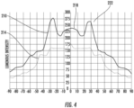
- Curve 210 may illustrate light output of the above disclosed embodiment while curve 214 may be light output compliant with the UL 1971 standard, or other specification detailing a minimum light output requirement, which governs many public mode fire applications in the Americas and the Middle East and is a performance standard (a similar performance standard, EN54, is primarily used in Europe).
- UL 1971 includes specific light output and distribution requirements to ensure illumination throughout a defined area. The requirements stipulate a minimum flash rate of between about 1Hz and 2Hz (e.g., about 1.2 Hz), categorizes minimum light intensities by area: non-sleeping (15 cd), corridor (15 cd) and sleeping areas (110 cd for walls or 177 cd for ceilings).
- the UL 1971 standard requires a polar light distribution pattern to enhance the likelihood of alerting hearing impaired individuals throughout an area that an emergency such as a first is occurring (the pattern also includes "compound 45s" - eight light spots around a cross).
- the term "polar” refers to the way the standard measures light intensity: both horizontally and vertically at viewing angles ranging from 0 to 180 degrees.
- the light output of the disclosed embodiments may meet and/or exceed the minimum standards illustrated in FIG. 4 along the entire distribution pattern.
- the light output of the disclosed embodiments may be concentrated in directed locations about the lens 100. For example, in comparison with light emitted at the third portion 152 of the lens 100, illustrated by curve portion 218, other areas about the lens 108 may provide yet stronger illumination, as illustrated by curve portion 222.
- the lens 100 design has been shaped to provide light intensity output all about the surface of the lens that wherein the light is significantly more intense than otherwise available for the LEDs therein.
- the luminosity of a packed (7) seven LED board may meet or exceed the luminosity of a packed (10) ten LED board having the same type of LED elements.
- Benefits of the disclosed design may include focusing and directing and distributing light from a board of packed LEDs to maximize light directionality.
Landscapes
- Physics & Mathematics (AREA)
- General Physics & Mathematics (AREA)
- Optics & Photonics (AREA)
- Electromagnetism (AREA)
- Lenses (AREA)
- Led Device Packages (AREA)
Description
- Exemplary embodiments pertain to the art of visual alarm detectors (VADs) and more specifically to a configuration of a lens for a VAD.
- VAD designs may use a set often (10) light emitting diodes (LED) to provide strobe light output. Such designs may provide at least a threshold minimum amount of lighting. Utilizing fewer LEDs may be desirable in a configuration that may provide at least the threshold minimum amount of lighting.
-
US2011/0080736 A1 relates to a lens for a flashlight or other lighting unit. A lens provides for focusing light from a source, such as an LED, to provide a light beam adjustable between a spot beam and a wide beam. The lens includes a lens body with a front face, a rear LED-receiving well, and a side surface extending between the front face and the rear well. The front face includes a central surface surrounded by an annular concave surface. The rear well includes a space for the LED to be adjusted in position. The rear well space is defined by a concavely-curved sidewall and a concavely-curved base. - The present invention provides a lens for covering an array of light emitting diodes (LEDs) mounted to a printed circuit board (PCB) in a visual alarm device (VAD), the lens being a dome lens extending upwardly in an axial direction about a center axis A and outwardly in a radial direction R, the lens comprising: a first portion which is a bottom portion, the first potion forming a first annular ring about the center axis A, the first portion including a first inner surface , a first outer surface and a bottom surface, wherein the first portion is oriented so that a first tangent to the first inner surface is at a first angle to the center axis A wherein the first angle is less than forty-five degrees, a second portion which is an intermediate portion, the second portion being continuous with the first portion, the second portion forming a second annular ring about the center axis A, the second portion including a second inner surface and a second outer surface, wherein the second portion is oriented so that a second tangent to the second inner surface is canted toward the center axis A, a third portion which is a top portion that is continuous with the second portion to enclose the lens, the third potion forming an annular solid disk about the center axis A, the third portion including a third inner surface and a third outer surface. The first inner surface, the second inner surface and the third inner surface together form a lens composite inner surface that is aberration-free and continuous. The first outer surface, the second outer surface and the third outer surface are each convex and together form a lens composite outer surface that is an aberration-free and continuous dome. The lens includes a fourth portion which is a base portion that extends axially below the first portion, the fourth portion being cylindrical and having a fourth outer surface that is continuous with the first outer surface, and a fourth inner surface that extends downwardly from the bottom surface of the first portion, wherein the fourth inner surface and the bottom surface are configured to be positioned against the PCB.
- In addition to one or more of the above disclosed features, or as an alternative, the first angle is less than thirty degrees.
- In addition to one or more of the above disclosed features, or as an alternative, the first tangent to the first inner surface is substantially parallel to the center axis A.
- In addition to one or more of the above disclosed features, or as an alternative, a bottom surface of the first portion is substantially planar.
- In addition to one or more of the above disclosed features, or as an alternative, wherein the lens is thickest along the bottom surface of the first portion.
- In addition to one or more of the above disclosed features, or as an alternative, the lens is thinnest at a first interface between the second portion and the third portion.
- In addition to one or more of the above disclosed features, or as an alternative, the lens continuously increases in thickness in the second portion between the first interface and a second interface between the first portion and the second portion.
- In addition to one or more of the above disclosed features, or as an alternative, the lens continuously increases in thickness in the first portion between the second interface and the bottom surface.
- Further disclosed is a visual alarm device (VAD) comprising: a printed circuit board (PCB) including an array of light emitting diodes (LEDs); and a lens covering the PCB, the lens having one or more of the above disclosed features. Yet further disclosed is a method of refracting light from an array of LEDs in a visual alarm device VAD comprising directing light from the array of LEDs through a lens, the lens comprising one or more of the above disclosed features.
- The following descriptions should not be considered limiting in any way. With reference to the accompanying drawings, like elements are numbered alike:
-
FIG. 1 illustrates a VAD according to an embodiment;FIG. 2 illustrates cross sectional view of a lens according to an embodiment; -
FIG. 3 illustrates a cross sectional view of a lens and printed circuit board according to an embodiment; and -
FIG. 4 illustrates light output according to a disclosed embodiment. - A detailed description of one or more embodiments of the disclosed apparatus and method are presented herein by way of exemplification and not limitation with reference to the Figures.
- Turning to
FIGS. 1 and 2 , disclosed is alens 100 for covering anarray 104 of light emitting diodes (LEDs) mounted to a printed circuit board PCB 106 in a visual alarm device (VAD) 108. The array includes seven LEDs in a packed configuration. Thelens 100 may be a dome lens extending upwardly in an axial direction about a center axis A and outwardly in a radial direction R. - The
lens 100 has afirst portion 120, which is a bottom portion. Thefirst potion 120 forms a first annular ring about the center axis A. Thefirst portion 120 includes a firstinner surface 124 that is convex and a firstouter surface 128, the shape of which is discussed below. Thefirst portion 120 is oriented so that afirst tangent 132 to the firstinner surface 124 is at afirst angle 133 to the center axis A, wherein thefirst angle 133 is less than forty-five degrees, more specifically or as an alternative thefirst angle 133 is less than thirty degrees, and more specifically or as an alternative thefirst tangent 132 to the firstinner surface 124 is substantially parallel to the center axis A. - A
second portion 136 of thelens 100 is an intermediate portion. Thesecond portion 136 is continuous with thefirst portion 120. Thesecond portion 136 forms a second annular ring about the center axis A. Thesecond portion 136 includes a secondinner surface 140 that is convex and a secondouter surface 144, the shape of which is discussed below. Thesecond portion 136 is oriented so that asecond tangent 148 to the secondinner surface 140 is canted toward the center axis A. The canted angle may be an acute angle and may be forty-five degrees. - A
third portion 152 of thelens 100 is a top portion. Thethird portion 152 is continuous with thesecond portion 136 to enclose thelens 100. Thethird potion 152 forms an annular solid disk about the center axis A. Thethird portion 152 includes a thirdinner surface 156 that is convex and a thirdouter surface 160, the shape of which is discussed below. - As illustrated in
FIG. 2 , the firstinner surface 124, the secondinner surface 140 and the thirdinner surface 156 together form a lens composite inner surface that is aberration-free and continuous. In addition the firstouter surface 128, the secondouter surface 144 and the thirdouter surface 160 each is convex and together form a lens composite outer surface that is an aberration-free and continuous dome. In addition, the lens composite outer surface is substantially hemispherical. - As further illustrated in
FIG. 2 , abottom surface 164 of thebottom portion 120 may be substantially planar. This may to provide a base on a PCB board. - To provide desired optics, the
lens 100 may be thickest along thebottom surface 164 of thefirst portion 120 and thelens 100 may be thinnest at afirst interface 168 between thesecond portion 136 and thethird portion 152. In addition, thelens 100 may continuously increase in thickness in thesecond portion 136 between thefirst interface 168 and asecond interface 172 between thefirst portion 120 and thesecond portion 136. Further, as illustrated, thelens 100 may continuously increase in thickness in thefirst portion 120 between thesecond interface 172 and thebottom surface 164. - For reasons discussed below, a
bottom edge 175 of the firstouter surface 128 may be circular having an outer surface diameter DO. The contour and shape of the outer surface of thelens 100 above thebottom edge 175, however, may be a function of the above identified geometry and optics. In one embodiment, cross sectional slices of thelens 100 that are parallel to and above thebottom edge 175 of the firstouter surface 128 may be circular. - As further illustrated, the
lens 100 includes afourth portion 176 that is a base portion that extends axially below thefirst portion 120. Thefourth portion 176 is cylindrical and has a fourthouter surface 180 that is continuous with the firstouter surface 128. Thefourth portion 176 includes a fourthinner surface 188 that extends downwardly from thebottom surface 164 of thefirst portion 120. The fourthinner surface 188 forms a PCB centering flange having a flange height HF and flange diameter DF that, along with thebottom surface 164 of thelens 100, are configured to receive thePCB 106 of thearray 104 of LEDs. As illustrated, the flange diameter DF may form the diameter of thebottom surface 164. - The
fourth portion 176 may include aradially extending lip 192 configured to be gripped by a retaining structure within theVAD 108 to secure thelens 100 within theVAD 108. Materials used for manufacturing thelens 100 may include acrylic, polycarbonate, or the like. - The
PCB 106 is illustrated having a thickness or span in the axial direction A of the lens that may be substantially HF. In addition, thePCB 106 has an outer diameter that may be substantially DF. Turning toFIG.3 , thelens 100 is illustrated wherein thelip 192 in thefourth portion 176 has been omitted for clarity of discussion. The height of anLED element 200 may be HL. To obtain the above described optics, a first height H1 of thefirst portion 120 may be between seventy five percent of HL and three times HL, that is 0.75*HL<H1<3*HL. In one embodiment, H1 may be substantially the same as HL. In addition, a second height H2 of thesecond portion 136 may be between three and five times HL, that is 3*HL<H2<5*HL, and in oneembodiment 3*HL<H2<4*HL. - The outer diameter of the
LED array 104 may be DL. A first diameter D1 of thefirst portion 120 at thebottom surface 164 may be between one and a quarter and two times DL, or 1.25*DL<D1<2*DL. In addition a second diameter D2 at thesecond interface 172 between thefirst portion 120 and thesecond portion 136 may be between one and one and a half times DL, or DL<D2<1.5*DL. A third diameter D3 at thefirst interface 168 of thesecond portion 136 andthird portion 152 may be between one-half and one times DL, or 0.5*DL<D3<DL. - The ranges and ratios identified herein for the disclosed embodiments are for reference only. One of ordinary skill reading this document would readily understand that the disclosed ranges and ratios are not intended to be limiting. For example, where an LED element has a height that differs from HL, and/or an array of LEDS has a diameter that differs from DL, lens designs falling outside the ranges disclosed herein that provide benefits identified herein would fall within the scope of this disclosure.
- Turning to
FIG. 4 , light output from the above configuration is illustrated.Curve 210 may illustrate light output of the above disclosed embodiment whilecurve 214 may be light output compliant with the UL 1971 standard, or other specification detailing a minimum light output requirement, which governs many public mode fire applications in the Americas and the Middle East and is a performance standard (a similar performance standard, EN54, is primarily used in Europe). UL 1971 includes specific light output and distribution requirements to ensure illumination throughout a defined area. The requirements stipulate a minimum flash rate of between about 1Hz and 2Hz (e.g., about 1.2 Hz), categorizes minimum light intensities by area: non-sleeping (15 cd), corridor (15 cd) and sleeping areas (110 cd for walls or 177 cd for ceilings). In particular, the UL 1971 standard requires a polar light distribution pattern to enhance the likelihood of alerting hearing impaired individuals throughout an area that an emergency such as a first is occurring (the pattern also includes "compound 45s" - eight light spots around a cross). The term "polar" refers to the way the standard measures light intensity: both horizontally and vertically at viewing angles ranging from 0 to 180 degrees. - As illustrated, the light output of the disclosed embodiments may meet and/or exceed the minimum standards illustrated in
FIG. 4 along the entire distribution pattern. In addition, the light output of the disclosed embodiments may be concentrated in directed locations about thelens 100. For example, in comparison with light emitted at thethird portion 152 of thelens 100, illustrated bycurve portion 218, other areas about thelens 108 may provide yet stronger illumination, as illustrated bycurve portion 222. - Accordingly, the
lens 100 design has been shaped to provide light intensity output all about the surface of the lens that wherein the light is significantly more intense than otherwise available for the LEDs therein. For example, the luminosity of a packed (7) seven LED board may meet or exceed the luminosity of a packed (10) ten LED board having the same type of LED elements. Benefits of the disclosed design may include focusing and directing and distributing light from a board of packed LEDs to maximize light directionality. - The term "about" is intended to include the degree of error associated with measurement of the particular quantity based upon the equipment available at the time of filing the application. The terminology used herein is for the purpose of describing particular embodiments only and is not intended to be limiting of the present disclosure. As used herein, the singular forms "a", "an" and "the" are intended to include the plural forms as well, unless the context clearly indicates otherwise. It will be further understood that the terms "comprises" and/or "comprising," when used in this specification, specify the presence of stated features, integers, steps, operations, elements, and/or components, but do not preclude the presence or addition of one or more other features, integers, steps, operations, element components, and/or groups thereof.
- While the present disclosure has been described with reference to an exemplary embodiment or embodiments, it will be understood by those skilled in the art that various changes may be made without departing from the scope of the present disclosure. In addition, many modifications may be made to adapt a particular situation or material to the teachings of the present disclosure without departing from the essential scope thereof. Therefore, it is intended that the present disclosure not be limited to the particular embodiment disclosed as the best mode contemplated for carrying out this present disclosure, but that the present disclosure will include all embodiments falling within the scope of the claims.
Claims (11)
- A lens (100) for covering an array (104) of light emitting diodes (LED) mounted to a printed circuit board (PCB) (106) in a visual alarm device (VAD) (108), the lens (100) being a dome lens extending upwardly in an axial direction about a center axis (A) and outwardly in a radial direction (R), the lens (100) comprising:a first portion (120) which is a bottom portion, the first potion (120) forming a first annular ring about the center axis (A), the first portion (120) including a first inner surface (124), a first outer surface (128) and a bottom surface (164), wherein the first portion (120) is oriented so that a first tangent (132) to the first inner surface (124) is at a first angle to the center axis (A), wherein the first angle is less than forty-five degrees,a second portion (136) which is an intermediate portion, the second portion (136) being continuous with the first portion (120), the second portion (136) forming a second annular ring about the center axis (A), the second portion (136) including a second inner surface (140) and a second outer surface (144), wherein the second portion (136) is oriented so that a second tangent (148) to the second inner surface (140) is canted toward the center axis (A),a third portion (152) which is a top portion that is continuous with the second portion (136) to enclose the lens (100), the third potion (152) forming an annular solid disk about the center axis (A), the third portion (152) including a third inner surface (156) and a third outer surface (160),wherein the first inner surface (124), the second inner surface (140) and the third inner surface (156) together form a lens composite inner surface that is aberration-free and continuous;wherein the first outer surface (128), the second outer surface (144) and the third outer surface (160) are each convex and together form a lens composite outer surface that is an aberration-free and continuous dome; andcharacterised in thatthe lens (100) includes a fourth portion (176) which is a base portion that extends axially below the first portion (120), the fourth portion (176) being cylindrical and having a fourth outer surface (180) that is continuous with the first outer surface (128), and a fourth inner surface (188) that extends downwardly from the bottom surface (164) of the first portion (120), wherein the fourth inner surface (188) and the bottom surface (164) are configured to be positioned against the PCB (106).
- The lens (100) of claim 1 wherein the first angle is less than thirty degrees.
- The lens (100) of claim 1 wherein the first tangent to the first inner surface is substantially parallel to the center axis A.
- The lens (100) of claim 1 wherein a bottom surface (164) of the first portion (120) is substantially planar.
- The lens (100) of claim 1 wherein the lens (100) is thickest along the bottom surface (164) of the first portion (120).
- The lens (100) of claim 5 wherein the lens (100) is thinnest at a first interface (168) between the second portion (136) and the third portion (152).
- The lens (100) of claim 6 wherein the lens (100) continuously increases in thickness in the second portion (136) between the first interface (168) and a second interface (172) between the first portion (120) and the second portion (136).
- The lens (100) of claim 7 wherein the lens (100) continuously increases in thickness in the first portion (120) between the second interface (172) and the bottom surface (164).
- A visual alarm device (VAD) (108) comprising:a printed circuit board (PCB) (106) including an array (104) of light emitting diodes (LED); andthe lens (100) of any preceding claim covering the PCB (106), the lens (100) being a dome lens extending upwardly in an axial direction about a center axis (A) and outwardly in a radial direction (R).
- A method of refracting light from an array (106) of LEDs in a visual alarm device (VAD) comprising directing light from the array of LEDs through the lens (100) of claim 1
- The method of claim 10 wherein the lens (100) continuously increases in thickness in the second portion (136) between a first interface (168) between the second portion (136) and the third portion (152) and a second interface (172) between the first portion (120) and the second portion (136).
Applications Claiming Priority (2)
| Application Number | Priority Date | Filing Date | Title |
|---|---|---|---|
| US201862650848P | 2018-03-30 | 2018-03-30 | |
| PCT/US2019/024907 WO2019191631A1 (en) | 2018-03-30 | 2019-03-29 | Lens for a visual alarm detector |
Publications (2)
| Publication Number | Publication Date |
|---|---|
| EP3776052A1 EP3776052A1 (en) | 2021-02-17 |
| EP3776052B1 true EP3776052B1 (en) | 2024-06-19 |
Family
ID=66429523
Family Applications (1)
| Application Number | Title | Priority Date | Filing Date |
|---|---|---|---|
| EP19722297.9A Active EP3776052B1 (en) | 2018-03-30 | 2019-03-29 | Lens for a visual alarm detector |
Country Status (5)
| Country | Link |
|---|---|
| US (1) | US12094326B2 (en) |
| EP (1) | EP3776052B1 (en) |
| CA (1) | CA3095607A1 (en) |
| ES (1) | ES2982038T3 (en) |
| WO (1) | WO2019191631A1 (en) |
Family Cites Families (157)
| Publication number | Priority date | Publication date | Assignee | Title |
|---|---|---|---|---|
| US3875561A (en) | 1972-09-20 | 1975-04-01 | Hope Tronics Limited | Flashing vehicle warning beacon with lens and reflector |
| US3916209A (en) | 1973-07-24 | 1975-10-28 | Electro Signal Lab | Vaned baffle for optical smoke detector |
| US4340885A (en) | 1979-09-24 | 1982-07-20 | Super Shops, Inc. | Gas detector |
| US4827244A (en) | 1988-01-04 | 1989-05-02 | Pittway Corporation | Test initiation apparatus with continuous or pulse input |
| US4968860A (en) | 1988-05-19 | 1990-11-06 | Omron Tateisi Electronics Co. | Light emitting type push button switch |
| JPH0614338Y2 (en) | 1988-10-18 | 1994-04-13 | 日本開閉器工業株式会社 | Push button switch display button |
| US5103383A (en) | 1990-08-23 | 1992-04-07 | Mayhew Donald M | Emergency flasher |
| US5285037A (en) | 1992-04-10 | 1994-02-08 | Ampex Systems Corp. | Illuminated dome switch |
| US5391848A (en) | 1993-03-12 | 1995-02-21 | Inventio Ag | Push button switch illuminated by light emitting diodes for use with elevators |
| US5537003A (en) | 1994-04-08 | 1996-07-16 | Gentex Corporation | Control system for automotive vehicle headlamps and other vehicle equipment |
| US5392202A (en) | 1994-05-13 | 1995-02-21 | Fred M. Schildwachter & Sons, Inc. | Low profile illuminated push button |
| US5813519A (en) | 1996-05-03 | 1998-09-29 | Alps Electric Co., Ltd. | Lighted switch apparatus |
| US5785410A (en) | 1996-05-28 | 1998-07-28 | Branson, Sr.; Michael Del | Electronic road beacon |
| US5831538A (en) | 1997-03-18 | 1998-11-03 | Schena; Robert G. | Electrical fire hazard detector |
| US7385359B2 (en) | 1997-08-26 | 2008-06-10 | Philips Solid-State Lighting Solutions, Inc. | Information systems |
| USD412924S (en) | 1998-02-25 | 1999-08-17 | Star Micronics Co., Ltd. | Cover for a monitor camera |
| US6414801B1 (en) | 1999-01-14 | 2002-07-02 | Truck-Lite Co., Inc. | Catadioptric light emitting diode assembly |
| JP3765683B2 (en) | 1999-03-11 | 2006-04-12 | アルプス電気株式会社 | Illuminated switch device |
| US6348860B1 (en) | 1999-05-04 | 2002-02-19 | Lucent Technologies Inc. | Emergency evacuation reporting system and method for reporting an evacuation status from an affected area to a command center |
| US6425678B1 (en) | 1999-08-23 | 2002-07-30 | Dialight Corporation | Led obstruction lamp |
| US6678001B1 (en) | 1999-11-01 | 2004-01-13 | Elbex Video Ltd. | Ball shaped camera housing with simplified positioning |
| US20070020572A1 (en) | 1999-12-21 | 2007-01-25 | Furner Paul E | Candle and luminary light show |
| US7699603B2 (en) | 1999-12-21 | 2010-04-20 | S.C. Johnson & Son, Inc. | Multisensory candle assembly |
| DE10011624C1 (en) | 2000-03-10 | 2001-07-26 | Moeller Gmbh | Emergency cut-out button for electrical machine has depressed operating head held in depressed position by locking device and illuminated by internal light element |
| US6543911B1 (en) | 2000-05-08 | 2003-04-08 | Farlight Llc | Highly efficient luminaire having optical transformer providing precalculated angular intensity distribution and method therefore |
| GB2370903A (en) | 2001-01-08 | 2002-07-10 | Thorn Security | A fire detector |
| KR200262311Y1 (en) | 2001-10-27 | 2002-03-18 | 윤삼기 | Flasher of fire alarm lamp |
| JP4126937B2 (en) | 2002-03-13 | 2008-07-30 | オムロン株式会社 | Push button switch |
| US7068177B2 (en) | 2002-09-19 | 2006-06-27 | Honeywell International, Inc. | Multi-sensor device and methods for fire detection |
| DE10246056A1 (en) | 2002-10-02 | 2004-04-22 | Robert Bosch Gmbh | smoke detector |
| US6902287B2 (en) | 2002-11-14 | 2005-06-07 | Safety Technology International, Inc. | Environmentally controlled appliance enclosure |
| US6914534B2 (en) | 2002-11-20 | 2005-07-05 | Maple Chase Company | Enhanced visual signaling for an adverse condition detector |
| KR200307344Y1 (en) | 2002-12-06 | 2003-03-15 | 신동윤 | A warning for a fire sensing |
| USD556235S1 (en) | 2002-12-23 | 2007-11-27 | Aigis Mechtronics, Llc | Vandal resistant camera housing |
| USD497927S1 (en) | 2003-06-02 | 2004-11-02 | Pelco | Camera mount and enclosure |
| US7023004B2 (en) | 2003-10-23 | 2006-04-04 | Timothy Ford | Multi-mode electromagnetic radiation emitting device |
| US7079041B2 (en) | 2003-11-21 | 2006-07-18 | Whelen Engineering Company, Inc. | LED aircraft anticollision beacon |
| USD513477S1 (en) | 2004-05-18 | 2006-01-10 | Nicotech Limited | Beacon |
| US20050258973A1 (en) | 2004-05-21 | 2005-11-24 | Kidsmart Corp. | Smoke detector with fire drill system |
| USD544805S1 (en) | 2005-09-09 | 2007-06-19 | Electronic Controls Company | Warning light |
| TWD113100S1 (en) | 2005-09-16 | 2006-09-21 | 廣威國際有限公司 | Monitor |
| USD558248S1 (en) | 2005-09-30 | 2007-12-25 | Elmo Co., Ltd. | Surveillance television camera |
| US7636049B2 (en) | 2005-12-14 | 2009-12-22 | Ellul Jr Joseph | Emergency notification and directional signaling apparatus |
| TWM297018U (en) | 2006-01-02 | 2006-09-01 | First Lite Inc | Lighted membrane switch and lighted keyboard using the same |
| CA2857896C (en) | 2006-02-10 | 2017-09-12 | The Flewelling Ford Family Trust | Light emitting and receiving device |
| US9860965B2 (en) | 2006-03-28 | 2018-01-02 | Wireless Environment, Llc | Cloud connected lighting system |
| US7592923B2 (en) | 2006-06-07 | 2009-09-22 | L.I.F.E. Support Technologies, Llc | Smoke detection and laser escape indication system utilizing a control master with base and satellite stations |
| US7478914B2 (en) | 2006-06-16 | 2009-01-20 | Finkle Louis J | Liquid motion lamp with temperature control system |
| US7791595B2 (en) | 2006-06-20 | 2010-09-07 | Lutron Electronics Co., Inc. | Touch screen assembly for a lighting control |
| USD564557S1 (en) | 2006-07-26 | 2008-03-18 | Victor Company Of Japan, Limited | Surveillance camera |
| US20130293098A1 (en) * | 2006-08-03 | 2013-11-07 | Intematix Corporation | Solid-state linear lighting arrangements including light emitting phosphor |
| USD591697S1 (en) | 2006-08-09 | 2009-05-05 | Cree, Inc. | Lamp package |
| USD560244S1 (en) | 2006-08-29 | 2008-01-22 | Kabushiki Kaisha Toshiba | Camera for monitoring |
| USD584756S1 (en) | 2006-09-13 | 2009-01-13 | Panasonic Corporation | Surveillance camera |
| JP4825140B2 (en) * | 2007-01-15 | 2011-11-30 | 株式会社小糸製作所 | Vehicle lighting |
| USD570722S1 (en) | 2007-02-02 | 2008-06-10 | Nicotech Limited | Beacon |
| US8628219B2 (en) | 2007-09-12 | 2014-01-14 | Dialight Corporation | Compact omnidirectional LED light |
| CA124208S (en) | 2008-01-15 | 2008-09-23 | Sws Star Warning Systems Inc | Bioptic warning beacon |
| USD605966S1 (en) | 2008-01-24 | 2009-12-15 | Hosiden Besson Limited | Alarm sounder/beacon |
| US8141422B2 (en) | 2008-04-25 | 2012-03-27 | Hall David L | Detector housing |
| USD598316S1 (en) | 2008-06-12 | 2009-08-18 | Patlite Corporation | Globe for revolving warning light |
| DE102008029698C5 (en) | 2008-06-24 | 2014-12-18 | Geze Gmbh | door control unit |
| US20100073172A1 (en) | 2008-09-25 | 2010-03-25 | L.I.F.E. Support Technologies, Llc | Dual condition fire/smoke detector with adjustable led cannon |
| USD592088S1 (en) | 2008-10-13 | 2009-05-12 | Code 3, Inc. | Light emitting diode (LED) warning light |
| US8049427B2 (en) | 2008-11-25 | 2011-11-01 | Lutron Electronics Co., Inc. | Load control device having a visual indication of energy savings and usage information |
| GB0821963D0 (en) | 2008-12-02 | 2009-01-07 | Newman Matthew J | Battery powered, sleeper gsm unit twinned with a battery powered smoke alarm |
| US8237377B2 (en) | 2008-12-11 | 2012-08-07 | Michael Blair Hopper | Energy efficient lighting system and method |
| US8232884B2 (en) | 2009-04-24 | 2012-07-31 | Gentex Corporation | Carbon monoxide and smoke detectors having distinct alarm indications and a test button that indicates improper operation |
| CN101936500A (en) * | 2009-06-30 | 2011-01-05 | 富准精密工业(深圳)有限公司 | LED Module |
| USD616780S1 (en) | 2009-07-01 | 2010-06-01 | Whelen Engineering Company, Inc. | Warning light and flange |
| CN102753889B (en) | 2009-08-28 | 2016-08-31 | 路易斯·芬克尔 | Thermal Flow Lamp |
| USD612760S1 (en) | 2009-09-22 | 2010-03-30 | Code 3, Inc. | Light emitting diode beacon light |
| US8777449B2 (en) | 2009-09-25 | 2014-07-15 | Cree, Inc. | Lighting devices comprising solid state light emitters |
| US8371710B2 (en) * | 2009-10-02 | 2013-02-12 | Coast Cutlery Company | Focusing lens system |
| USD644677S1 (en) | 2009-12-10 | 2011-09-06 | Cnb Technology Inc. | Camera for closed circuit television |
| USD647553S1 (en) | 2009-12-10 | 2011-10-25 | Cnb Technology Inc. | Camera for closed circuit television |
| US20110187543A1 (en) | 2010-02-04 | 2011-08-04 | Linda Russo | Home safety 911 system |
| US8242899B2 (en) | 2010-02-09 | 2012-08-14 | InnovAlaem Corporation | Supplemental alert generation device for retrofit applications |
| US7997764B1 (en) | 2010-02-28 | 2011-08-16 | Nielson Lewis A | Flashing light module for a traffic safety cone |
| USD633120S1 (en) | 2010-04-13 | 2011-02-22 | Cnb Technology Inc. | Camera for closed circuit television |
| USD628225S1 (en) | 2010-04-14 | 2010-11-30 | Robert Bosch Gmbh | Housing for surveillance camera |
| USD639843S1 (en) | 2010-10-08 | 2011-06-14 | March Networks Corporation | Video surveillance camera |
| USD639328S1 (en) | 2010-10-08 | 2011-06-07 | March Networks Corporation | Video surveillance camera |
| JP5582305B2 (en) | 2010-11-18 | 2014-09-03 | 東芝ライテック株式会社 | Lamp apparatus and lighting apparatus |
| US20120160642A1 (en) | 2010-12-22 | 2012-06-28 | Hung-Min Liao | Switch unit |
| US20120238319A1 (en) | 2011-03-16 | 2012-09-20 | Colin Patrick Lake | System and method for combined alarm detection and emergency signaling |
| DE102011100036B4 (en) | 2011-04-29 | 2018-11-29 | Assa Abloy Sicherheitstechnik Gmbh | A method of operating an emergency button and using a display of an emergency button |
| CN102789916A (en) | 2011-05-20 | 2012-11-21 | 祝慧 | Novel warning emergency stop button device |
| FR2975809A1 (en) | 2011-05-23 | 2012-11-30 | Selvarasa Nageswaran | Lighting device for lighting and detecting/warning presence of smoke and/or hazardous gases e.g. carbon-dioxide, has non-flammable PVC base and non-flammable PVC cover including hole at its center for installation of energy-saving bulb |
| CN102214653B (en) | 2011-05-31 | 2013-02-13 | 宁波市鄞州雷迈半导体科技有限公司 | Packaging structure of high-power LED (light-emitting diode) chip |
| US20120321321A1 (en) | 2011-06-14 | 2012-12-20 | Scott Riesebosch | Methods of communication utilizing an led lamp |
| USD660738S1 (en) | 2011-09-16 | 2012-05-29 | Ningbo Yinzhou Self Photoelectron Technology Co., Ltd. | LED beacon |
| TWI377709B (en) * | 2011-10-18 | 2012-11-21 | E Pin Optical Industry Co Ltd | Led lens and light source device using the same |
| US8547036B2 (en) | 2011-11-20 | 2013-10-01 | Available For Licensing | Solid state light system with broadband optical communication capability |
| TW201235707A (en) * | 2011-12-14 | 2012-09-01 | E Pin Optical Industry Co Ltd | LED lens and light emitting device using the same |
| US9553451B2 (en) | 2011-12-28 | 2017-01-24 | Lutron Electronics Co., Inc. | Load control system having independently-controlled units responsive to a broadcast controller |
| USD673869S1 (en) | 2012-03-05 | 2013-01-08 | Ningbo Yinzhou Self Photoelectron Technology Co., Ltd. | LED strobe light |
| CN202852641U (en) | 2012-03-06 | 2013-04-03 | 宁波市鄞州赛艾富光电科技有限公司 | LED warning lamp single body |
| USD669806S1 (en) | 2012-04-18 | 2012-10-30 | Code 3, Inc. | Light emitting diode beacon light |
| USD669807S1 (en) | 2012-04-18 | 2012-10-30 | Code 3, Inc. | Light emitting diode beacon light |
| US8907802B2 (en) | 2012-04-29 | 2014-12-09 | Valor Fire Safety, Llc | Smoke detector with external sampling volume and ambient light rejection |
| USD709782S1 (en) | 2012-05-16 | 2014-07-29 | Werma Holding Gmbh + Co. Kg | Alarm device |
| CN103515131A (en) | 2012-06-27 | 2014-01-15 | 徐州康腾传动科技发展有限公司 | Novel sudden stop button structure |
| US20150145406A1 (en) * | 2012-06-28 | 2015-05-28 | Intematix Corporation | Solid-state linear lighting arrangements including light emitting phosphor |
| US9228713B2 (en) | 2012-08-31 | 2016-01-05 | Federal Signal Corporation | Light beacon assembly |
| US9007222B2 (en) | 2012-09-21 | 2015-04-14 | Google Inc. | Detector unit and sensing chamber therefor |
| USD684078S1 (en) | 2012-09-24 | 2013-06-11 | Checkers Industrial Products, Llc | LED strobe light |
| US9035786B2 (en) | 2012-09-24 | 2015-05-19 | Checkers Industrial Products, Llc | LED strobe light with peripheral pattern display |
| CN203188142U (en) | 2012-12-16 | 2013-09-11 | 四川久远新方向智能科技有限公司 | Station control room standby plate emergency button of automatic rail transit fare collection system |
| US10566148B2 (en) | 2013-01-30 | 2020-02-18 | Banner Engineering Corporation | Switch with circumferential indicator light |
| US9618184B2 (en) | 2013-03-15 | 2017-04-11 | Walter Kidde Portable Equipment Inc. | Alarm with reflector ring |
| US9791117B2 (en) | 2013-04-02 | 2017-10-17 | Thomas & Betts International Llc | Emergency lighting fixture with remote control |
| WO2014162131A1 (en) | 2013-04-05 | 2014-10-09 | Mc Donagh Bernard | Emergency exit sign |
| USD740870S1 (en) | 2013-04-09 | 2015-10-13 | Hanwha Techwin Co., Ltd. | Dome camera |
| USD701466S1 (en) | 2013-04-16 | 2014-03-25 | Checkers Industrial Products, Llc | LED strobe light with heat sink chimney |
| US20140340913A1 (en) | 2013-05-18 | 2014-11-20 | Hong Juan Cui | Led light bulb and manufacturing method of the same |
| US9345098B2 (en) | 2013-05-31 | 2016-05-17 | Stack Labs, Inc. | Systems and methods for providing a self-adjusting light source |
| CA2926811C (en) | 2013-10-07 | 2023-03-21 | Google Inc. | Smart-home hazard detector providing context specific features and/or pre-alarm configurations |
| CN105794170B (en) | 2013-10-07 | 2019-11-15 | 谷歌有限责任公司 | Method and system for establishing smart home device and online management account pairing |
| US9622321B2 (en) | 2013-10-11 | 2017-04-11 | Cree, Inc. | Systems, devices and methods for controlling one or more lights |
| US9251675B2 (en) | 2013-10-23 | 2016-02-02 | Honeywell International Inc. | Multiple LED omni-directional visual alarm device |
| US9288877B2 (en) | 2014-01-27 | 2016-03-15 | Cree, Inc. | Sensor module for a lighting fixture |
| US9799175B2 (en) | 2014-05-06 | 2017-10-24 | White Stagg, Llc | Signal device with indirect lighting signal |
| US9549448B2 (en) | 2014-05-30 | 2017-01-17 | Cree, Inc. | Wall controller controlling CCT |
| TWM488825U (en) | 2014-06-20 | 2014-10-21 | Shu-Chen Guo | Active type illumination light source module and lamp with intelligent function for automatically controlling intensity of illumination |
| USD742447S1 (en) | 2014-07-11 | 2015-11-03 | Avigilon Corporation | Trim ring with dome |
| WO2016008050A1 (en) | 2014-07-15 | 2016-01-21 | The Flewelling Ford Family Trust | Environmentally protected switch and device using same |
| US9875630B2 (en) | 2014-07-30 | 2018-01-23 | Tyco Fire & Security Gmbh | Notification appliance |
| US9430925B2 (en) | 2014-09-05 | 2016-08-30 | Google Inc. | Detector unit and sensing chamber therefor with matter retention member and method for making same |
| TWI537668B (en) | 2014-09-24 | 2016-06-11 | 晶睿通訊股份有限公司 | Image monitoring apparatus |
| BR112017008410A2 (en) | 2014-10-23 | 2017-12-19 | Oy Mtg Meltron Ltd | hazardous area light fixture |
| US9970599B2 (en) | 2016-07-24 | 2018-05-15 | Xiamen Eco Lighting Co. Ltd. | Light bulb apparatus |
| WO2016179655A1 (en) | 2015-05-13 | 2016-11-17 | Beyer Peter Ernest | Lighting system with integrated smoke detector |
| US9466194B1 (en) | 2015-05-15 | 2016-10-11 | Google Inc. | Hazard detector architecture facilitating compact form factor and multi-protocol wireless connectivity |
| TWM512667U (en) | 2015-06-23 | 2015-11-21 | Unity Opto Technology Co Ltd | Automatic sensing and dimming lamp |
| US9705597B2 (en) | 2015-08-12 | 2017-07-11 | Electronic Controls Company | Modular light bar messaging system |
| CN105222010A (en) | 2015-09-17 | 2016-01-06 | 京东方光科技有限公司 | A kind of Down lamp and illuminator |
| US10352553B2 (en) | 2015-09-30 | 2019-07-16 | Hallmark Cards, Incorporated | Apparatus for producing light and sound |
| US20170140619A1 (en) | 2015-11-17 | 2017-05-18 | Linda Russo | Wireless home safety 911 system |
| CN106816332A (en) | 2015-11-27 | 2017-06-09 | 南宁富桂精密工业有限公司 | Press-key structure and the electronic installation with the press-key structure |
| US9746167B2 (en) | 2015-12-23 | 2017-08-29 | Pass & Seymour, Inc. | Electrical wiring device having a bidirectional light pipe for use in an ambient environment |
| US10613213B2 (en) | 2016-05-13 | 2020-04-07 | Google Llc | Systems, methods, and devices for utilizing radar with smart devices |
| USD798934S1 (en) | 2016-07-22 | 2017-10-03 | Avigilon Corporation | Dome camera |
| US20180212371A1 (en) | 2017-01-20 | 2018-07-26 | Guangdong Bestek E-Commerce Co., Ltd. | Automatic light control devices and sockets |
| US10819921B2 (en) | 2017-05-25 | 2020-10-27 | Google Llc | Camera assembly having a single-piece cover element |
| CA3069426A1 (en) | 2017-07-10 | 2019-01-17 | Carrier Corporation | Hazard detector with optical status indicator |
| CA3069508A1 (en) | 2017-07-10 | 2019-01-17 | Carrier Corporation | Hazard detector with optical status indicator |
| CN206989056U (en) | 2017-08-11 | 2018-02-09 | 周调彪 | Livestock-raising light fixture with cigarette sense warning device |
| US20190052027A1 (en) | 2017-08-14 | 2019-02-14 | Darrin Jensen | Support lighting for electrical power systems |
| US10375471B2 (en) | 2017-08-30 | 2019-08-06 | Amazon Technologies, Inc. | Voice controlled assistant |
| CN107680855A (en) | 2017-09-01 | 2018-02-09 | 东莞市凯华电子有限公司 | A kind of luminous key switch in centre |
| US10914431B2 (en) | 2017-12-31 | 2021-02-09 | Google Llc | Smart-home device light rings with tapered transmissive sections for uniform output |
| US10492272B2 (en) | 2018-03-20 | 2019-11-26 | Xiamen Eco Lighting Co. Ltd. | LED sensing light driving circuit |
| US10825313B2 (en) | 2018-03-30 | 2020-11-03 | Carrier Corporation | Hazard detector with optical status indicator |
| CA3093004C (en) | 2018-04-06 | 2021-08-17 | Terry LACY | Hazardous condition detector with wireless communication interface |
| USD931749S1 (en) | 2019-09-10 | 2021-09-28 | Yunlong Zhong | Carbon monoxide detector |
| US11423071B1 (en) | 2021-08-31 | 2022-08-23 | On Time Staffing, Inc. | Candidate data ranking method using previously selected candidate data |
-
2019
- 2019-03-29 ES ES19722297T patent/ES2982038T3/en active Active
- 2019-03-29 WO PCT/US2019/024907 patent/WO2019191631A1/en not_active Ceased
- 2019-03-29 CA CA3095607A patent/CA3095607A1/en active Pending
- 2019-03-29 US US17/042,643 patent/US12094326B2/en active Active
- 2019-03-29 EP EP19722297.9A patent/EP3776052B1/en active Active
Also Published As
| Publication number | Publication date |
|---|---|
| EP3776052A1 (en) | 2021-02-17 |
| CA3095607A1 (en) | 2019-10-03 |
| US20210035419A1 (en) | 2021-02-04 |
| US12094326B2 (en) | 2024-09-17 |
| ES2982038T3 (en) | 2024-10-14 |
| WO2019191631A1 (en) | 2019-10-03 |
Similar Documents
| Publication | Publication Date | Title |
|---|---|---|
| US10895365B2 (en) | Lighting apparatus with reflector and outer lens | |
| US8931938B2 (en) | Locomotive LED/optics headlight assembly | |
| US6525668B1 (en) | LED array warning light system | |
| US10139095B2 (en) | Reflector and lamp comprised thereof | |
| US7841748B2 (en) | Diffractor-diffuser system for a fluorescent lumen package | |
| CA2493828A1 (en) | Full cutoff area light fixture | |
| US9858772B2 (en) | Lens, light-emitting device having the lens, and visual notification appliance | |
| US9827898B2 (en) | Vehicle light assembly with multiple light arrays | |
| EP2979023A1 (en) | Lighting device and luminaire | |
| US12094326B2 (en) | Lens for a visual alarm detector | |
| CN108139576A (en) | Optical element, illuminating device and lamps and lanterns | |
| CN108074359B (en) | Alarm device | |
| JP2016538682A (en) | Lighting device and lighting fixture | |
| JP4970624B1 (en) | Lighting device | |
| EP3298322B1 (en) | Tubular light emitting device | |
| CN222597487U (en) | Light distribution structure and lighting equipment | |
| TWI554722B (en) | A lens structure and a light source module using the lens structure | |
| JP2016157656A (en) | Light-emitting device and lighting fixture using the same | |
| JP5595065B2 (en) | lighting equipment | |
| JP2015179594A (en) | marker lamp | |
| JP2020053251A (en) | Lens and lighting device | |
| JP2014216239A (en) | Led lighting device | |
| TWM527523U (en) | Light engine reflection cup body | |
| US20100053949A1 (en) | Led lamp |
Legal Events
| Date | Code | Title | Description |
|---|---|---|---|
| STAA | Information on the status of an ep patent application or granted ep patent |
Free format text: STATUS: UNKNOWN |
|
| STAA | Information on the status of an ep patent application or granted ep patent |
Free format text: STATUS: THE INTERNATIONAL PUBLICATION HAS BEEN MADE |
|
| PUAI | Public reference made under article 153(3) epc to a published international application that has entered the european phase |
Free format text: ORIGINAL CODE: 0009012 |
|
| STAA | Information on the status of an ep patent application or granted ep patent |
Free format text: STATUS: REQUEST FOR EXAMINATION WAS MADE |
|
| 17P | Request for examination filed |
Effective date: 20201005 |
|
| AK | Designated contracting states |
Kind code of ref document: A1 Designated state(s): AL AT BE BG CH CY CZ DE DK EE ES FI FR GB GR HR HU IE IS IT LI LT LU LV MC MK MT NL NO PL PT RO RS SE SI SK SM TR |
|
| AX | Request for extension of the european patent |
Extension state: BA ME |
|
| DAV | Request for validation of the european patent (deleted) | ||
| DAX | Request for extension of the european patent (deleted) | ||
| STAA | Information on the status of an ep patent application or granted ep patent |
Free format text: STATUS: EXAMINATION IS IN PROGRESS |
|
| 17Q | First examination report despatched |
Effective date: 20221116 |
|
| P01 | Opt-out of the competence of the unified patent court (upc) registered |
Effective date: 20230527 |
|
| GRAP | Despatch of communication of intention to grant a patent |
Free format text: ORIGINAL CODE: EPIDOSNIGR1 |
|
| STAA | Information on the status of an ep patent application or granted ep patent |
Free format text: STATUS: GRANT OF PATENT IS INTENDED |
|
| INTG | Intention to grant announced |
Effective date: 20240108 |
|
| GRAS | Grant fee paid |
Free format text: ORIGINAL CODE: EPIDOSNIGR3 |
|
| GRAA | (expected) grant |
Free format text: ORIGINAL CODE: 0009210 |
|
| STAA | Information on the status of an ep patent application or granted ep patent |
Free format text: STATUS: THE PATENT HAS BEEN GRANTED |
|
| AK | Designated contracting states |
Kind code of ref document: B1 Designated state(s): AL AT BE BG CH CY CZ DE DK EE ES FI FR GB GR HR HU IE IS IT LI LT LU LV MC MK MT NL NO PL PT RO RS SE SI SK SM TR |
|
| REG | Reference to a national code |
Ref country code: GB Ref legal event code: FG4D |
|
| REG | Reference to a national code |
Ref country code: CH Ref legal event code: EP |
|
| REG | Reference to a national code |
Ref country code: DE Ref legal event code: R096 Ref document number: 602019053864 Country of ref document: DE |
|
| PG25 | Lapsed in a contracting state [announced via postgrant information from national office to epo] |
Ref country code: BG Free format text: LAPSE BECAUSE OF FAILURE TO SUBMIT A TRANSLATION OF THE DESCRIPTION OR TO PAY THE FEE WITHIN THE PRESCRIBED TIME-LIMIT Effective date: 20240619 |
|
| PG25 | Lapsed in a contracting state [announced via postgrant information from national office to epo] |
Ref country code: HR Free format text: LAPSE BECAUSE OF FAILURE TO SUBMIT A TRANSLATION OF THE DESCRIPTION OR TO PAY THE FEE WITHIN THE PRESCRIBED TIME-LIMIT Effective date: 20240619 Ref country code: FI Free format text: LAPSE BECAUSE OF FAILURE TO SUBMIT A TRANSLATION OF THE DESCRIPTION OR TO PAY THE FEE WITHIN THE PRESCRIBED TIME-LIMIT Effective date: 20240619 |
|
| REG | Reference to a national code |
Ref country code: LT Ref legal event code: MG9D |
|
| PG25 | Lapsed in a contracting state [announced via postgrant information from national office to epo] |
Ref country code: GR Free format text: LAPSE BECAUSE OF FAILURE TO SUBMIT A TRANSLATION OF THE DESCRIPTION OR TO PAY THE FEE WITHIN THE PRESCRIBED TIME-LIMIT Effective date: 20240920 |
|
| REG | Reference to a national code |
Ref country code: ES Ref legal event code: FG2A Ref document number: 2982038 Country of ref document: ES Kind code of ref document: T3 Effective date: 20241014 |
|
| REG | Reference to a national code |
Ref country code: NL Ref legal event code: MP Effective date: 20240619 |
|
| PG25 | Lapsed in a contracting state [announced via postgrant information from national office to epo] |
Ref country code: LV Free format text: LAPSE BECAUSE OF FAILURE TO SUBMIT A TRANSLATION OF THE DESCRIPTION OR TO PAY THE FEE WITHIN THE PRESCRIBED TIME-LIMIT Effective date: 20240619 |
|
| PG25 | Lapsed in a contracting state [announced via postgrant information from national office to epo] |
Ref country code: NO Free format text: LAPSE BECAUSE OF FAILURE TO SUBMIT A TRANSLATION OF THE DESCRIPTION OR TO PAY THE FEE WITHIN THE PRESCRIBED TIME-LIMIT Effective date: 20240919 Ref country code: LV Free format text: LAPSE BECAUSE OF FAILURE TO SUBMIT A TRANSLATION OF THE DESCRIPTION OR TO PAY THE FEE WITHIN THE PRESCRIBED TIME-LIMIT Effective date: 20240619 Ref country code: HR Free format text: LAPSE BECAUSE OF FAILURE TO SUBMIT A TRANSLATION OF THE DESCRIPTION OR TO PAY THE FEE WITHIN THE PRESCRIBED TIME-LIMIT Effective date: 20240619 Ref country code: GR Free format text: LAPSE BECAUSE OF FAILURE TO SUBMIT A TRANSLATION OF THE DESCRIPTION OR TO PAY THE FEE WITHIN THE PRESCRIBED TIME-LIMIT Effective date: 20240920 Ref country code: FI Free format text: LAPSE BECAUSE OF FAILURE TO SUBMIT A TRANSLATION OF THE DESCRIPTION OR TO PAY THE FEE WITHIN THE PRESCRIBED TIME-LIMIT Effective date: 20240619 Ref country code: BG Free format text: LAPSE BECAUSE OF FAILURE TO SUBMIT A TRANSLATION OF THE DESCRIPTION OR TO PAY THE FEE WITHIN THE PRESCRIBED TIME-LIMIT Effective date: 20240619 Ref country code: RS Free format text: LAPSE BECAUSE OF FAILURE TO SUBMIT A TRANSLATION OF THE DESCRIPTION OR TO PAY THE FEE WITHIN THE PRESCRIBED TIME-LIMIT Effective date: 20240919 |
|
| PG25 | Lapsed in a contracting state [announced via postgrant information from national office to epo] |
Ref country code: NL Free format text: LAPSE BECAUSE OF FAILURE TO SUBMIT A TRANSLATION OF THE DESCRIPTION OR TO PAY THE FEE WITHIN THE PRESCRIBED TIME-LIMIT Effective date: 20240619 |
|
| REG | Reference to a national code |
Ref country code: AT Ref legal event code: MK05 Ref document number: 1696278 Country of ref document: AT Kind code of ref document: T Effective date: 20240619 |
|
| PG25 | Lapsed in a contracting state [announced via postgrant information from national office to epo] |
Ref country code: NL Free format text: LAPSE BECAUSE OF FAILURE TO SUBMIT A TRANSLATION OF THE DESCRIPTION OR TO PAY THE FEE WITHIN THE PRESCRIBED TIME-LIMIT Effective date: 20240619 |
|
| PG25 | Lapsed in a contracting state [announced via postgrant information from national office to epo] |
Ref country code: PT Free format text: LAPSE BECAUSE OF FAILURE TO SUBMIT A TRANSLATION OF THE DESCRIPTION OR TO PAY THE FEE WITHIN THE PRESCRIBED TIME-LIMIT Effective date: 20241021 |
|
| PG25 | Lapsed in a contracting state [announced via postgrant information from national office to epo] |
Ref country code: PT Free format text: LAPSE BECAUSE OF FAILURE TO SUBMIT A TRANSLATION OF THE DESCRIPTION OR TO PAY THE FEE WITHIN THE PRESCRIBED TIME-LIMIT Effective date: 20241021 |
|
| PG25 | Lapsed in a contracting state [announced via postgrant information from national office to epo] |
Ref country code: PL Free format text: LAPSE BECAUSE OF FAILURE TO SUBMIT A TRANSLATION OF THE DESCRIPTION OR TO PAY THE FEE WITHIN THE PRESCRIBED TIME-LIMIT Effective date: 20240619 |
|
| PG25 | Lapsed in a contracting state [announced via postgrant information from national office to epo] |
Ref country code: EE Free format text: LAPSE BECAUSE OF FAILURE TO SUBMIT A TRANSLATION OF THE DESCRIPTION OR TO PAY THE FEE WITHIN THE PRESCRIBED TIME-LIMIT Effective date: 20240619 |
|
| PG25 | Lapsed in a contracting state [announced via postgrant information from national office to epo] |
Ref country code: AT Free format text: LAPSE BECAUSE OF FAILURE TO SUBMIT A TRANSLATION OF THE DESCRIPTION OR TO PAY THE FEE WITHIN THE PRESCRIBED TIME-LIMIT Effective date: 20240619 Ref country code: IS Free format text: LAPSE BECAUSE OF FAILURE TO SUBMIT A TRANSLATION OF THE DESCRIPTION OR TO PAY THE FEE WITHIN THE PRESCRIBED TIME-LIMIT Effective date: 20241019 |
|
| PG25 | Lapsed in a contracting state [announced via postgrant information from national office to epo] |
Ref country code: CZ Free format text: LAPSE BECAUSE OF FAILURE TO SUBMIT A TRANSLATION OF THE DESCRIPTION OR TO PAY THE FEE WITHIN THE PRESCRIBED TIME-LIMIT Effective date: 20240619 |
|
| PG25 | Lapsed in a contracting state [announced via postgrant information from national office to epo] |
Ref country code: SK Free format text: LAPSE BECAUSE OF FAILURE TO SUBMIT A TRANSLATION OF THE DESCRIPTION OR TO PAY THE FEE WITHIN THE PRESCRIBED TIME-LIMIT Effective date: 20240619 Ref country code: RO Free format text: LAPSE BECAUSE OF FAILURE TO SUBMIT A TRANSLATION OF THE DESCRIPTION OR TO PAY THE FEE WITHIN THE PRESCRIBED TIME-LIMIT Effective date: 20240619 |
|
| PG25 | Lapsed in a contracting state [announced via postgrant information from national office to epo] |
Ref country code: SM Free format text: LAPSE BECAUSE OF FAILURE TO SUBMIT A TRANSLATION OF THE DESCRIPTION OR TO PAY THE FEE WITHIN THE PRESCRIBED TIME-LIMIT Effective date: 20240619 |
|
| PG25 | Lapsed in a contracting state [announced via postgrant information from national office to epo] |
Ref country code: SM Free format text: LAPSE BECAUSE OF FAILURE TO SUBMIT A TRANSLATION OF THE DESCRIPTION OR TO PAY THE FEE WITHIN THE PRESCRIBED TIME-LIMIT Effective date: 20240619 Ref country code: SK Free format text: LAPSE BECAUSE OF FAILURE TO SUBMIT A TRANSLATION OF THE DESCRIPTION OR TO PAY THE FEE WITHIN THE PRESCRIBED TIME-LIMIT Effective date: 20240619 Ref country code: RO Free format text: LAPSE BECAUSE OF FAILURE TO SUBMIT A TRANSLATION OF THE DESCRIPTION OR TO PAY THE FEE WITHIN THE PRESCRIBED TIME-LIMIT Effective date: 20240619 Ref country code: PL Free format text: LAPSE BECAUSE OF FAILURE TO SUBMIT A TRANSLATION OF THE DESCRIPTION OR TO PAY THE FEE WITHIN THE PRESCRIBED TIME-LIMIT Effective date: 20240619 Ref country code: IS Free format text: LAPSE BECAUSE OF FAILURE TO SUBMIT A TRANSLATION OF THE DESCRIPTION OR TO PAY THE FEE WITHIN THE PRESCRIBED TIME-LIMIT Effective date: 20241019 Ref country code: EE Free format text: LAPSE BECAUSE OF FAILURE TO SUBMIT A TRANSLATION OF THE DESCRIPTION OR TO PAY THE FEE WITHIN THE PRESCRIBED TIME-LIMIT Effective date: 20240619 Ref country code: CZ Free format text: LAPSE BECAUSE OF FAILURE TO SUBMIT A TRANSLATION OF THE DESCRIPTION OR TO PAY THE FEE WITHIN THE PRESCRIBED TIME-LIMIT Effective date: 20240619 Ref country code: AT Free format text: LAPSE BECAUSE OF FAILURE TO SUBMIT A TRANSLATION OF THE DESCRIPTION OR TO PAY THE FEE WITHIN THE PRESCRIBED TIME-LIMIT Effective date: 20240619 |
|
| PG25 | Lapsed in a contracting state [announced via postgrant information from national office to epo] |
Ref country code: IT Free format text: LAPSE BECAUSE OF FAILURE TO SUBMIT A TRANSLATION OF THE DESCRIPTION OR TO PAY THE FEE WITHIN THE PRESCRIBED TIME-LIMIT Effective date: 20240619 |
|
| REG | Reference to a national code |
Ref country code: DE Ref legal event code: R097 Ref document number: 602019053864 Country of ref document: DE |
|
| PG25 | Lapsed in a contracting state [announced via postgrant information from national office to epo] |
Ref country code: DK Free format text: LAPSE BECAUSE OF FAILURE TO SUBMIT A TRANSLATION OF THE DESCRIPTION OR TO PAY THE FEE WITHIN THE PRESCRIBED TIME-LIMIT Effective date: 20240619 |
|
| PLBE | No opposition filed within time limit |
Free format text: ORIGINAL CODE: 0009261 |
|
| STAA | Information on the status of an ep patent application or granted ep patent |
Free format text: STATUS: NO OPPOSITION FILED WITHIN TIME LIMIT |
|
| 26N | No opposition filed |
Effective date: 20250320 |
|
| PGFP | Annual fee paid to national office [announced via postgrant information from national office to epo] |
Ref country code: ES Payment date: 20250401 Year of fee payment: 7 |
|
| PG25 | Lapsed in a contracting state [announced via postgrant information from national office to epo] |
Ref country code: SE Free format text: LAPSE BECAUSE OF FAILURE TO SUBMIT A TRANSLATION OF THE DESCRIPTION OR TO PAY THE FEE WITHIN THE PRESCRIBED TIME-LIMIT Effective date: 20240619 |
|
| REG | Reference to a national code |
Ref country code: DE Ref legal event code: R119 Ref document number: 602019053864 Country of ref document: DE |
|
| PG25 | Lapsed in a contracting state [announced via postgrant information from national office to epo] |
Ref country code: MC Free format text: LAPSE BECAUSE OF FAILURE TO SUBMIT A TRANSLATION OF THE DESCRIPTION OR TO PAY THE FEE WITHIN THE PRESCRIBED TIME-LIMIT Effective date: 20240619 |
|
| REG | Reference to a national code |
Ref country code: CH Ref legal event code: H13 Free format text: ST27 STATUS EVENT CODE: U-0-0-H10-H13 (AS PROVIDED BY THE NATIONAL OFFICE) Effective date: 20251023 |
|
| PG25 | Lapsed in a contracting state [announced via postgrant information from national office to epo] |
Ref country code: LU Free format text: LAPSE BECAUSE OF NON-PAYMENT OF DUE FEES Effective date: 20250329 |
|
| REG | Reference to a national code |
Ref country code: BE Ref legal event code: MM Effective date: 20250331 |
|
| PG25 | Lapsed in a contracting state [announced via postgrant information from national office to epo] |
Ref country code: DE Free format text: LAPSE BECAUSE OF NON-PAYMENT OF DUE FEES Effective date: 20251001 |
|
| PG25 | Lapsed in a contracting state [announced via postgrant information from national office to epo] |
Ref country code: BE Free format text: LAPSE BECAUSE OF NON-PAYMENT OF DUE FEES Effective date: 20250331 |
|
| PG25 | Lapsed in a contracting state [announced via postgrant information from national office to epo] |
Ref country code: CH Free format text: LAPSE BECAUSE OF NON-PAYMENT OF DUE FEES Effective date: 20250331 |
|
| PG25 | Lapsed in a contracting state [announced via postgrant information from national office to epo] |
Ref country code: IE Free format text: LAPSE BECAUSE OF NON-PAYMENT OF DUE FEES Effective date: 20250329 |
|
| PGFP | Annual fee paid to national office [announced via postgrant information from national office to epo] |
Ref country code: GB Payment date: 20260219 Year of fee payment: 8 |
|
| PGFP | Annual fee paid to national office [announced via postgrant information from national office to epo] |
Ref country code: FR Payment date: 20260219 Year of fee payment: 8 |