EP3775749B1 - Bi-directional self-energizing gaskets - Google Patents
Bi-directional self-energizing gaskets Download PDFInfo
- Publication number
- EP3775749B1 EP3775749B1 EP19780864.5A EP19780864A EP3775749B1 EP 3775749 B1 EP3775749 B1 EP 3775749B1 EP 19780864 A EP19780864 A EP 19780864A EP 3775749 B1 EP3775749 B1 EP 3775749B1
- Authority
- EP
- European Patent Office
- Prior art keywords
- gasket
- main body
- self
- inlet
- tubesheet
- Prior art date
- Legal status (The legal status is an assumption and is not a legal conclusion. Google has not performed a legal analysis and makes no representation as to the accuracy of the status listed.)
- Active
Links
Images


Classifications
-
- F—MECHANICAL ENGINEERING; LIGHTING; HEATING; WEAPONS; BLASTING
- F16—ENGINEERING ELEMENTS AND UNITS; GENERAL MEASURES FOR PRODUCING AND MAINTAINING EFFECTIVE FUNCTIONING OF MACHINES OR INSTALLATIONS; THERMAL INSULATION IN GENERAL
- F16J—PISTONS; CYLINDERS; SEALINGS
- F16J15/00—Sealings
- F16J15/16—Sealings between relatively-moving surfaces
- F16J15/164—Sealings between relatively-moving surfaces the sealing action depending on movements; pressure difference, temperature or presence of leaking fluid
-
- F—MECHANICAL ENGINEERING; LIGHTING; HEATING; WEAPONS; BLASTING
- F28—HEAT EXCHANGE IN GENERAL
- F28D—HEAT-EXCHANGE APPARATUS, NOT PROVIDED FOR IN ANOTHER SUBCLASS, IN WHICH THE HEAT-EXCHANGE MEDIA DO NOT COME INTO DIRECT CONTACT
- F28D7/00—Heat-exchange apparatus having stationary tubular conduit assemblies for both heat-exchange media, the media being in contact with different sides of a conduit wall
- F28D7/06—Heat-exchange apparatus having stationary tubular conduit assemblies for both heat-exchange media, the media being in contact with different sides of a conduit wall the conduits having a single U-bend
-
- F—MECHANICAL ENGINEERING; LIGHTING; HEATING; WEAPONS; BLASTING
- F16—ENGINEERING ELEMENTS AND UNITS; GENERAL MEASURES FOR PRODUCING AND MAINTAINING EFFECTIVE FUNCTIONING OF MACHINES OR INSTALLATIONS; THERMAL INSULATION IN GENERAL
- F16J—PISTONS; CYLINDERS; SEALINGS
- F16J15/00—Sealings
- F16J15/02—Sealings between relatively-stationary surfaces
- F16J15/06—Sealings between relatively-stationary surfaces with solid packing compressed between sealing surfaces
- F16J15/062—Sealings between relatively-stationary surfaces with solid packing compressed between sealing surfaces characterised by the geometry of the seat
-
- F—MECHANICAL ENGINEERING; LIGHTING; HEATING; WEAPONS; BLASTING
- F16—ENGINEERING ELEMENTS AND UNITS; GENERAL MEASURES FOR PRODUCING AND MAINTAINING EFFECTIVE FUNCTIONING OF MACHINES OR INSTALLATIONS; THERMAL INSULATION IN GENERAL
- F16J—PISTONS; CYLINDERS; SEALINGS
- F16J15/00—Sealings
- F16J15/02—Sealings between relatively-stationary surfaces
- F16J15/06—Sealings between relatively-stationary surfaces with solid packing compressed between sealing surfaces
- F16J15/08—Sealings between relatively-stationary surfaces with solid packing compressed between sealing surfaces with exclusively metal packing
- F16J15/0881—Sealings between relatively-stationary surfaces with solid packing compressed between sealing surfaces with exclusively metal packing the sealing effect being obtained by plastic deformation of the packing
-
- F—MECHANICAL ENGINEERING; LIGHTING; HEATING; WEAPONS; BLASTING
- F16—ENGINEERING ELEMENTS AND UNITS; GENERAL MEASURES FOR PRODUCING AND MAINTAINING EFFECTIVE FUNCTIONING OF MACHINES OR INSTALLATIONS; THERMAL INSULATION IN GENERAL
- F16J—PISTONS; CYLINDERS; SEALINGS
- F16J15/00—Sealings
- F16J15/46—Sealings with packing ring expanded or pressed into place by fluid pressure, e.g. inflatable packings
- F16J15/48—Sealings with packing ring expanded or pressed into place by fluid pressure, e.g. inflatable packings influenced by the pressure within the member to be sealed
-
- F—MECHANICAL ENGINEERING; LIGHTING; HEATING; WEAPONS; BLASTING
- F28—HEAT EXCHANGE IN GENERAL
- F28D—HEAT-EXCHANGE APPARATUS, NOT PROVIDED FOR IN ANOTHER SUBCLASS, IN WHICH THE HEAT-EXCHANGE MEDIA DO NOT COME INTO DIRECT CONTACT
- F28D7/00—Heat-exchange apparatus having stationary tubular conduit assemblies for both heat-exchange media, the media being in contact with different sides of a conduit wall
- F28D7/16—Heat-exchange apparatus having stationary tubular conduit assemblies for both heat-exchange media, the media being in contact with different sides of a conduit wall the conduits being arranged in parallel spaced relation
-
- F—MECHANICAL ENGINEERING; LIGHTING; HEATING; WEAPONS; BLASTING
- F28—HEAT EXCHANGE IN GENERAL
- F28F—DETAILS OF HEAT-EXCHANGE AND HEAT-TRANSFER APPARATUS, OF GENERAL APPLICATION
- F28F9/00—Casings; Header boxes; Auxiliary supports for elements; Auxiliary members within casings
- F28F9/02—Header boxes; End plates
- F28F9/0219—Arrangements for sealing end plates into casing or header box; Header box sub-elements
- F28F9/0224—Header boxes formed by sealing end plates into covers
- F28F9/0226—Header boxes formed by sealing end plates into covers with resilient gaskets
-
- F—MECHANICAL ENGINEERING; LIGHTING; HEATING; WEAPONS; BLASTING
- F16—ENGINEERING ELEMENTS AND UNITS; GENERAL MEASURES FOR PRODUCING AND MAINTAINING EFFECTIVE FUNCTIONING OF MACHINES OR INSTALLATIONS; THERMAL INSULATION IN GENERAL
- F16J—PISTONS; CYLINDERS; SEALINGS
- F16J15/00—Sealings
- F16J15/16—Sealings between relatively-moving surfaces
- F16J15/32—Sealings between relatively-moving surfaces with elastic sealings, e.g. O-rings
- F16J15/3204—Sealings between relatively-moving surfaces with elastic sealings, e.g. O-rings with at least one lip
- F16J15/3224—Sealings between relatively-moving surfaces with elastic sealings, e.g. O-rings with at least one lip capable of accommodating changes in distances or misalignment between the surfaces, e.g. able to compensate for defaults of eccentricity or angular deviations
-
- F—MECHANICAL ENGINEERING; LIGHTING; HEATING; WEAPONS; BLASTING
- F16—ENGINEERING ELEMENTS AND UNITS; GENERAL MEASURES FOR PRODUCING AND MAINTAINING EFFECTIVE FUNCTIONING OF MACHINES OR INSTALLATIONS; THERMAL INSULATION IN GENERAL
- F16L—PIPES; JOINTS OR FITTINGS FOR PIPES; SUPPORTS FOR PIPES, CABLES OR PROTECTIVE TUBING; MEANS FOR THERMAL INSULATION IN GENERAL
- F16L17/00—Joints with packing adapted to sealing by fluid pressure
- F16L17/06—Joints with packing adapted to sealing by fluid pressure with sealing rings arranged between the end surfaces of the pipes or flanges or arranged in recesses in the pipe ends or flanges
- F16L17/08—Metal sealing rings
-
- F—MECHANICAL ENGINEERING; LIGHTING; HEATING; WEAPONS; BLASTING
- F16—ENGINEERING ELEMENTS AND UNITS; GENERAL MEASURES FOR PRODUCING AND MAINTAINING EFFECTIVE FUNCTIONING OF MACHINES OR INSTALLATIONS; THERMAL INSULATION IN GENERAL
- F16L—PIPES; JOINTS OR FITTINGS FOR PIPES; SUPPORTS FOR PIPES, CABLES OR PROTECTIVE TUBING; MEANS FOR THERMAL INSULATION IN GENERAL
- F16L5/00—Devices for use where pipes, cables or protective tubing pass through walls or partitions
- F16L5/02—Sealing
- F16L5/10—Sealing by using sealing rings or sleeves only
-
- F—MECHANICAL ENGINEERING; LIGHTING; HEATING; WEAPONS; BLASTING
- F28—HEAT EXCHANGE IN GENERAL
- F28F—DETAILS OF HEAT-EXCHANGE AND HEAT-TRANSFER APPARATUS, OF GENERAL APPLICATION
- F28F2230/00—Sealing means
Definitions
- the present disclosure relates to seals and gaskets, and more particularly to self-energizing seals.
- Breech lock (or screw lock) heat exchangers have become a standard for special high pressure heat exchange applications.
- Traditional designs have leakage issues at the shell-to-tubesheet gasket, particularly after a rapid system shutdown or a plant trip. Upon restart of the heat exchangers, system process fluid leaks from the higher pressure side into the lower pressure side. This leakage is particularly noticeable in the first several heat exchangers of a heat exchanger network.
- US 2898000 A and WO 9809101 A1 show gaskets according to the preamble of claim 1 with axially spaced ridges, which are adapted to be clamped between two bodies.
- a heat exchanger includes a shell.
- a tubesheet is engaged to the shell.
- a plurality of tubes extend from the tubesheet and into the shell for heat exchange between a first fluid within the tubes and a second fluid in the shell outside the tubes.
- the tubesheet divides an interior of the shell into a heat exchange chamber where the tubes can exchange heat with the second fluid, an inlet-outlet chamber for the first fluid to enter and exit the tubes.
- a breech lock locks the tubesheet against the shell. The breech lock is spaced apart from the tubesheet across the inlet-outlet chamber.
- a bi-directionally self-energizing gasket is seated between the tubesheet and the shell to seal the heat exchange chamber from the inlet-outlet chamber. The gasket is configured to be self-energizing to seal regardless of whether there is a higher pressure in the heat exchange chamber or in the inlet-outlet chamber.
- the shell can include an inlet and an outlet for the first fluid.
- the inlet-outlet chamber can include an inlet and an outlet for the second fluid.
- the inlet-outlet chamber can be subdivided by a plate into an inlet section and an outlet section.
- Each of the tubes can have an inlet through the tubesheet in fluid communication with the inlet section and an outlet through the tubesheet in fluid communication with the outlet section.
- the gasket is annular and can be engaged axially between an annular face of the shell and an annular face of the tubesheet.
- the gasket can include any suitable material such as steel, stainless steel, delrin, plastic, bronze, and/or rubber.
- the main body of the gasket includes a radially inward opening self-energizing feature configured to increase sealing engagement with pressure in the heat exchange chamber.
- the radially inward opening self-energizing feature includes a pair of axially spaced ridges extending from the main body of the gasket on either side of an annular pocket that opens radially inward from the main body of the gasket.
- the radially inward opening self-energizing feature includes a pair of axially opposed annular channels in the main body of the gasket proximate the annular pocket to facilitate flexure of the ridges for self-energized sealing of the ridges against the shell and the tubesheet, respectively.
- the main body of the gasket includes a radially outward opening self-energizing feature configured to increase sealing engagement with pressure in the inlet-outlet chamber.
- the radially outward opening self-energizing feature includes a pair of axially spaced ridges extending from the main body of the gasket on either side of an annular pocket that opens radially outward from the main body of the gasket.
- the radially outward opening self-energizing feature includes a pair of axially opposed annular channels in the main body of the gasket proximate the annular pocket to facilitate flexure of the ridges for self-energized sealing of the ridges against the shell and the tubesheet, respectively.
- FIG. 1 a partial view of an exemplary embodiment of a heat exchanger in accordance with the disclosure is shown in Fig. 1 and is designated generally by reference character 100.
- the systems and methods described herein can be used to seal breech lock heat exchangers, for example, regardless of from which direction the high pressure is applied.
- the heat exchanger 100 includes a shell 102 that extends axially along a longitudinal axis A.
- a tubesheet 104 is engaged against the shell 102.
- a plurality of tubes 106 extend from the tubesheet 104 and into the shell 102 for heat exchange between a first fluid within the tubes 106 and a second fluid in the shell 102 outside the tubes 106.
- the tubesheet 104 divides the interior of the shell 102 into a heat exchange chamber 108 where the tubes 106 can exchange heat with the second fluid, an inlet-outlet chamber 110 for the first fluid to enter and exit the tubes 106.
- a breech lock 112 locks the tubesheet 104 within and against the shell 102.
- the breech lock 112 is spaced apart axially from the tubesheet 104 across the inlet-outlet chamber 110, also called the channel.
- the shell 102 includes an inlet 114 and an outlet 116 each in fluid communication with the heat exchange chamber 108 for circulation of the first fluid therein.
- the inlet-outlet chamber 110 includes an inlet 118 and an outlet 120 in fluid communication with the interior of the inlet-outlet chamber 110 for circulation of the second fluid therethrough.
- the inlet-outlet chamber 110 is subdivided by a plate 122 into an inlet section 124 and an outlet section 126.
- Each of the tubes 106 has an inlet 128 extended through the tubesheet 104 in fluid communication with the inlet section 124 and an outlet 130 extended through the tubesheet 104 in fluid communication with the outlet section 126.
- the breech lock 112 can apply an axial force on the tubesheet 104, pressing it against the shell 102, e.g., against the shoulder 103 of the shell 102.
- a bi-directionally self-energizing gasket 114 is seated between the tubesheet 104 and the shell 102 to seal the shell side heat exchange chamber 108 from the inlet-outlet channel side chamber 110.
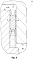
- the gasket 114 includes an annular main body 132, shown in Fig. 4 , and is engaged axially between an annular face 134 of the shell 102 and an annular face 136 of the tubesheet 104.
- the gasket 114 can be made of stainless steel for high pressure, high temperature, and/or highly corrosive fluids. Those skilled in the art will readily appreciation that any other suitable material, hard or soft, can be used for a given application such as steel, delrin, plastic, bronze, rubber, or the like, could be used for other chemical, temperature, and/or pressure applications including applications unrelated to the exemplary heat exchangers disclosed herein.
- the gasket 114 is configured to be self-energizing to seal with pressure from both sides regardless of whether there is a higher pressure in the heat exchange chamber 108 or in the inlet-outlet chamber 110. The sealing configuration can therefore work in both directions simultaneously.
- the main body 132 of the gasket 114 includes a radially inward opening self-energizing feature 138 configured to increase sealing engagement with pressure in the heat exchange chamber 108 and/or in the inlet-outlet chamber 110.
- the self-energizing feature 138 includes a pair of axially spaced ridges 140 extending from the main body of the gasket 114 on either side of an annular pocket 142 that opens radially inward from the main body 132 of the gasket 114.
- the self-energizing feature 138 includes a pair of axially opposed annular channels 144 in the main body of the gasket proximate the annular pocket 142 to facilitate flexure of the ridges 140 away from each other for self-energized sealing of the ridges 140 against the shell 102 and the tubesheet 104, respectively.
- the main body 132 of the gasket 114 also includes a radially outward opening self-energizing feature 146 configured to increase sealing engagement with pressure in the inlet-outlet chamber 110 of the heat exchange chamber.
- the self-energizing feature 146 includes a pair of axially spaced ridges 148 extending from the main body 132 of the gasket 114 on either side of an annular pocket 150 that opens radially outward from the main body 132 of the gasket 114.
- the self-energizing feature 146 includes a pair of axially opposed annular channels 152 in the main body 132 of the gasket 114 proximate the annular pocket 150 to facilitate flexure or deflection of the ridges 148 away from each other for self-energized sealing of the ridges 148 against the shell 102 and the tubesheet 104, respectively, as indicated by the pressure arrows in Fig. 5 .
- the gasket 114 can be initially seated by push rod forces from breech lock 112, and it can be reseated by pressure acting on the self-energizing features 138 and 146. Sealing the engagement of the shell 102 and the tubesheet 104 with gasket 114 prevents leakage to maintain separation of the first and second fluids in the tubes 106 and heat exchange chamber 108. Since the gasket 114 is self-energizing in response to pressure from the heat exchanger chamber 108 as well as in the opposite direction in response to the inlet-outlet chamber 110, the gasket 114 can provide sealing even when the pressure differential across the gasket 114 changes direction.
Landscapes
- Engineering & Computer Science (AREA)
- General Engineering & Computer Science (AREA)
- Mechanical Engineering (AREA)
- Physics & Mathematics (AREA)
- Thermal Sciences (AREA)
- Architecture (AREA)
- Fluid Mechanics (AREA)
- Geometry (AREA)
- Heat-Exchange Devices With Radiators And Conduit Assemblies (AREA)
- Gasket Seals (AREA)
Applications Claiming Priority (2)
| Application Number | Priority Date | Filing Date | Title |
|---|---|---|---|
| US15/946,896 US10808845B2 (en) | 2018-04-06 | 2018-04-06 | Bi-directional self-energizing gaskets |
| PCT/US2019/026281 WO2019195824A1 (en) | 2018-04-06 | 2019-04-08 | Bi-directional self-energizing gaskets |
Publications (3)
| Publication Number | Publication Date |
|---|---|
| EP3775749A1 EP3775749A1 (en) | 2021-02-17 |
| EP3775749A4 EP3775749A4 (en) | 2022-01-12 |
| EP3775749B1 true EP3775749B1 (en) | 2024-08-28 |
Family
ID=68098875
Family Applications (1)
| Application Number | Title | Priority Date | Filing Date |
|---|---|---|---|
| EP19780864.5A Active EP3775749B1 (en) | 2018-04-06 | 2019-04-08 | Bi-directional self-energizing gaskets |
Country Status (11)
| Country | Link |
|---|---|
| US (1) | US10808845B2 (https=) |
| EP (1) | EP3775749B1 (https=) |
| JP (2) | JP2021521399A (https=) |
| KR (1) | KR102790293B1 (https=) |
| CN (1) | CN112513554A (https=) |
| CA (1) | CA3096089A1 (https=) |
| ES (1) | ES2992337T3 (https=) |
| HU (1) | HUE069160T2 (https=) |
| PL (1) | PL3775749T3 (https=) |
| PT (1) | PT3775749T (https=) |
| WO (1) | WO2019195824A1 (https=) |
Families Citing this family (3)
| Publication number | Priority date | Publication date | Assignee | Title |
|---|---|---|---|---|
| JP6857100B2 (ja) * | 2017-07-31 | 2021-04-14 | Nok株式会社 | 密封装置 |
| USD1066609S1 (en) * | 2020-11-30 | 2025-03-11 | Siemens Energy Global GmbH & Co. KG | Sealing membrane |
| US20250189059A1 (en) * | 2023-12-06 | 2025-06-12 | Baker Hughes Oilfield Operations Llc | Deformable valve spacer ring system and method |
Citations (2)
| Publication number | Priority date | Publication date | Assignee | Title |
|---|---|---|---|---|
| US2898000A (en) * | 1957-01-30 | 1959-08-04 | United Aircraft Corp | O-ring pressure seal |
| US6540234B1 (en) * | 1996-08-29 | 2003-04-01 | Flexitallic Investments, Inc. | Gaskets |
Family Cites Families (24)
| Publication number | Priority date | Publication date | Assignee | Title |
|---|---|---|---|---|
| US3327777A (en) * | 1964-11-09 | 1967-06-27 | Union Carbide Corp | Heat interchanger |
| US3831950A (en) * | 1971-11-10 | 1974-08-27 | Chicago Bridge & Iron Co | Gasket for closure seal |
| JPS5620708Y2 (https=) * | 1973-11-27 | 1981-05-15 | ||
| EP0192015A1 (en) * | 1985-02-12 | 1986-08-27 | Valter Söderberg | A sealing device |
| JPH0241509Y2 (https=) * | 1985-08-20 | 1990-11-05 | ||
| US5518066A (en) * | 1994-05-27 | 1996-05-21 | Connell Limited Partnership | Heat exchanger |
| US6406028B1 (en) * | 1999-02-05 | 2002-06-18 | Schlumberger Technology Corporation | Seal stack |
| JP4928681B2 (ja) * | 2001-06-07 | 2012-05-09 | 三菱重工業株式会社 | メタルパッキン |
| US7021632B2 (en) * | 2004-03-04 | 2006-04-04 | Flowserve Management Company | Self-energized gasket and manufacturing method therefor |
| US20070024007A1 (en) * | 2005-07-28 | 2007-02-01 | Putch Samuel W | Seal ring and method |
| US7854254B2 (en) * | 2005-10-03 | 2010-12-21 | Taper-Lok Corporation | Systems and methods for making seals in heat exchangers |
| EP1837564A1 (de) * | 2006-03-23 | 2007-09-26 | Carl Freudenberg KG | Dichtring |
| EP2013562A2 (en) * | 2006-04-21 | 2009-01-14 | Larsen & Toubro Limited | Sealing arrangement for internal tubesheet for tubular heat exchangers |
| CN101849081B (zh) * | 2007-11-05 | 2014-06-18 | 卡梅伦国际有限公司 | 自紧式环形密封 |
| US8240672B2 (en) * | 2010-05-07 | 2012-08-14 | Flowserve Management Company | Low breakout friction energized gasket |
| JP5717662B2 (ja) * | 2012-01-27 | 2015-05-13 | 三菱電線工業株式会社 | 金属シール |
| US8936249B2 (en) * | 2012-03-02 | 2015-01-20 | Eaton Corporation | Resilient seal having a pressurized bellows spring |
| JP5102908B1 (ja) * | 2012-04-12 | 2012-12-19 | ニチアス株式会社 | 金属ガスケット |
| US9091349B2 (en) * | 2012-07-10 | 2015-07-28 | Hrst, Inc. | Self-energizing seal |
| JP5260773B1 (ja) * | 2012-08-01 | 2013-08-14 | ニチアス株式会社 | 金属ガスケット |
| FR2997324B1 (fr) * | 2012-10-31 | 2015-05-15 | Snecma | Joint statique metallique annulaire performant a bas cout pour hautes pressions et grands diametres |
| WO2016125773A1 (ja) * | 2015-02-02 | 2016-08-11 | 日本精工株式会社 | 車両用保舵判定装置及びそれを搭載した電動パワーステアリング装置 |
| US10550942B2 (en) * | 2015-07-28 | 2020-02-04 | Saint-Gobain Performance Plastics Corporation | Seals |
| JP6618818B2 (ja) * | 2016-01-22 | 2019-12-11 | 三菱日立パワーシステムズ株式会社 | 多管式熱交換器、その伝熱管洗浄方法 |
-
2018
- 2018-04-06 US US15/946,896 patent/US10808845B2/en active Active
-
2019
- 2019-04-08 EP EP19780864.5A patent/EP3775749B1/en active Active
- 2019-04-08 PL PL19780864.5T patent/PL3775749T3/pl unknown
- 2019-04-08 HU HUE19780864A patent/HUE069160T2/hu unknown
- 2019-04-08 ES ES19780864T patent/ES2992337T3/es active Active
- 2019-04-08 CN CN201980037401.5A patent/CN112513554A/zh active Pending
- 2019-04-08 PT PT197808645T patent/PT3775749T/pt unknown
- 2019-04-08 KR KR1020207031990A patent/KR102790293B1/ko active Active
- 2019-04-08 CA CA3096089A patent/CA3096089A1/en not_active Abandoned
- 2019-04-08 WO PCT/US2019/026281 patent/WO2019195824A1/en not_active Ceased
- 2019-04-08 JP JP2021504140A patent/JP2021521399A/ja active Pending
-
2023
- 2023-12-01 JP JP2023004332U patent/JP3245569U/ja active Active
Patent Citations (2)
| Publication number | Priority date | Publication date | Assignee | Title |
|---|---|---|---|---|
| US2898000A (en) * | 1957-01-30 | 1959-08-04 | United Aircraft Corp | O-ring pressure seal |
| US6540234B1 (en) * | 1996-08-29 | 2003-04-01 | Flexitallic Investments, Inc. | Gaskets |
Also Published As
| Publication number | Publication date |
|---|---|
| JP2021521399A (ja) | 2021-08-26 |
| HUE069160T2 (hu) | 2025-02-28 |
| EP3775749A1 (en) | 2021-02-17 |
| US10808845B2 (en) | 2020-10-20 |
| ES2992337T3 (es) | 2024-12-11 |
| EP3775749A4 (en) | 2022-01-12 |
| CA3096089A1 (en) | 2019-10-10 |
| CN112513554A (zh) | 2021-03-16 |
| US20190309851A1 (en) | 2019-10-10 |
| WO2019195824A1 (en) | 2019-10-10 |
| PT3775749T (pt) | 2024-10-15 |
| KR20210019408A (ko) | 2021-02-22 |
| JP3245569U (ja) | 2024-02-06 |
| KR102790293B1 (ko) | 2025-04-04 |
| PL3775749T3 (pl) | 2025-03-24 |
Similar Documents
| Publication | Publication Date | Title |
|---|---|---|
| JP3245569U (ja) | 二方向型の自己付勢ガスケット | |
| EP2531751B1 (en) | Unitized bi-directional seal assembly | |
| US9109732B2 (en) | EZ-seal gasket for joining fluid pathways | |
| EP2541106B1 (en) | Shaft-seal device for high-temperature fluid | |
| EP3270015B1 (en) | Floating ring mechanical seal | |
| TW202010966A (zh) | 膜片閥構造 | |
| US20150021908A1 (en) | High-Pressure Bi-Directional Sealing System | |
| US10794490B2 (en) | High pressure seal | |
| US20170328472A1 (en) | Interlocking annular pressure seal assembly | |
| CN108139180A (zh) | 用于热交换器的端口连接件 | |
| US3197218A (en) | Sealing means for a pressure vessel | |
| KR20190022932A (ko) | 압력 변화를 견디기 위한 상호연동 내경 밀봉 요소를 갖는 밀봉 시스템 | |
| US7966925B2 (en) | Combination mismatched metal-to-metal seal and O-ring seal with vent hole in between for high temperature and high pressure environment | |
| NO20151379A1 (en) | Improved Seal Assembly | |
| US10428959B2 (en) | Assembly for compressing a ball valve seat | |
| KR101895828B1 (ko) | 유로 연결을 위한 이지-실 개스킷 | |
| EP4370814B1 (en) | Seal for reciprocating pump | |
| EP4217627B1 (en) | Pressure retained gasket seal with enhanced unloading resistance | |
| GB2513183B (en) | Rotary coupling | |
| EP3431833B1 (en) | Metal to metal wedge ring seal | |
| HK1228485B (en) | Ez-seal assembly joining fluid pathways | |
| HK1228485A1 (en) | Ez-seal assembly joining fluid pathways | |
| WO2013105866A1 (en) | Access fitting for attaching a device within a process pipeline or vessel |
Legal Events
| Date | Code | Title | Description |
|---|---|---|---|
| STAA | Information on the status of an ep patent application or granted ep patent |
Free format text: STATUS: THE INTERNATIONAL PUBLICATION HAS BEEN MADE |
|
| PUAI | Public reference made under article 153(3) epc to a published international application that has entered the european phase |
Free format text: ORIGINAL CODE: 0009012 |
|
| STAA | Information on the status of an ep patent application or granted ep patent |
Free format text: STATUS: REQUEST FOR EXAMINATION WAS MADE |
|
| 17P | Request for examination filed |
Effective date: 20201019 |
|
| AK | Designated contracting states |
Kind code of ref document: A1 Designated state(s): AL AT BE BG CH CY CZ DE DK EE ES FI FR GB GR HR HU IE IS IT LI LT LU LV MC MK MT NL NO PL PT RO RS SE SI SK SM TR |
|
| AX | Request for extension of the european patent |
Extension state: BA ME |
|
| DAV | Request for validation of the european patent (deleted) | ||
| DAX | Request for extension of the european patent (deleted) | ||
| A4 | Supplementary search report drawn up and despatched |
Effective date: 20211210 |
|
| RIC1 | Information provided on ipc code assigned before grant |
Ipc: F28D 7/00 20060101ALI20211206BHEP Ipc: F16J 15/06 20060101ALI20211206BHEP Ipc: F16J 15/46 20060101ALI20211206BHEP Ipc: F28F 9/02 20060101AFI20211206BHEP |
|
| STAA | Information on the status of an ep patent application or granted ep patent |
Free format text: STATUS: EXAMINATION IS IN PROGRESS |
|
| 17Q | First examination report despatched |
Effective date: 20230522 |
|
| GRAP | Despatch of communication of intention to grant a patent |
Free format text: ORIGINAL CODE: EPIDOSNIGR1 |
|
| STAA | Information on the status of an ep patent application or granted ep patent |
Free format text: STATUS: GRANT OF PATENT IS INTENDED |
|
| INTG | Intention to grant announced |
Effective date: 20240408 |
|
| GRAS | Grant fee paid |
Free format text: ORIGINAL CODE: EPIDOSNIGR3 |
|
| GRAA | (expected) grant |
Free format text: ORIGINAL CODE: 0009210 |
|
| STAA | Information on the status of an ep patent application or granted ep patent |
Free format text: STATUS: THE PATENT HAS BEEN GRANTED |
|
| AK | Designated contracting states |
Kind code of ref document: B1 Designated state(s): AL AT BE BG CH CY CZ DE DK EE ES FI FR GB GR HR HU IE IS IT LI LT LU LV MC MK MT NL NO PL PT RO RS SE SI SK SM TR |
|
| REG | Reference to a national code |
Ref country code: GB Ref legal event code: FG4D |
|
| REG | Reference to a national code |
Ref country code: CH Ref legal event code: EP |
|
| REG | Reference to a national code |
Ref country code: DE Ref legal event code: R096 Ref document number: 602019057937 Country of ref document: DE |
|
| REG | Reference to a national code |
Ref country code: IE Ref legal event code: FG4D |
|
| REG | Reference to a national code |
Ref country code: PT Ref legal event code: SC4A Ref document number: 3775749 Country of ref document: PT Date of ref document: 20241015 Kind code of ref document: T Free format text: AVAILABILITY OF NATIONAL TRANSLATION Effective date: 20241009 |
|
| REG | Reference to a national code |
Ref country code: DE Ref legal event code: R081 Ref document number: 602019057937 Country of ref document: DE Owner name: THERMAL ENGINEERING INTERNATIONAL (USA) INC., , US Free format text: FORMER OWNER: THERMAL ENGINEERING INTERNATIONAL (USA) INC., SANTA FE SPRINGS, CA, US |
|
| REG | Reference to a national code |
Ref country code: ES Ref legal event code: FG2A Ref document number: 2992337 Country of ref document: ES Kind code of ref document: T3 Effective date: 20241211 |
|
| RAP4 | Party data changed (patent owner data changed or rights of a patent transferred) |
Owner name: THERMAL ENGINEERING INTERNATIONAL (USA) INC. |
|
| REG | Reference to a national code |
Ref country code: LT Ref legal event code: MG9D |
|
| PG25 | Lapsed in a contracting state [announced via postgrant information from national office to epo] |
Ref country code: NO Free format text: LAPSE BECAUSE OF FAILURE TO SUBMIT A TRANSLATION OF THE DESCRIPTION OR TO PAY THE FEE WITHIN THE PRESCRIBED TIME-LIMIT Effective date: 20241128 |
|
| REG | Reference to a national code |
Ref country code: AT Ref legal event code: MK05 Ref document number: 1718362 Country of ref document: AT Kind code of ref document: T Effective date: 20240828 |
|
| PG25 | Lapsed in a contracting state [announced via postgrant information from national office to epo] |
Ref country code: NL Free format text: LAPSE BECAUSE OF FAILURE TO SUBMIT A TRANSLATION OF THE DESCRIPTION OR TO PAY THE FEE WITHIN THE PRESCRIBED TIME-LIMIT Effective date: 20240828 Ref country code: FI Free format text: LAPSE BECAUSE OF FAILURE TO SUBMIT A TRANSLATION OF THE DESCRIPTION OR TO PAY THE FEE WITHIN THE PRESCRIBED TIME-LIMIT Effective date: 20240828 Ref country code: GR Free format text: LAPSE BECAUSE OF FAILURE TO SUBMIT A TRANSLATION OF THE DESCRIPTION OR TO PAY THE FEE WITHIN THE PRESCRIBED TIME-LIMIT Effective date: 20241129 |
|
| PG25 | Lapsed in a contracting state [announced via postgrant information from national office to epo] |
Ref country code: BG Free format text: LAPSE BECAUSE OF FAILURE TO SUBMIT A TRANSLATION OF THE DESCRIPTION OR TO PAY THE FEE WITHIN THE PRESCRIBED TIME-LIMIT Effective date: 20240828 |
|
| PG25 | Lapsed in a contracting state [announced via postgrant information from national office to epo] |
Ref country code: LV Free format text: LAPSE BECAUSE OF FAILURE TO SUBMIT A TRANSLATION OF THE DESCRIPTION OR TO PAY THE FEE WITHIN THE PRESCRIBED TIME-LIMIT Effective date: 20240828 |
|
| REG | Reference to a national code |
Ref country code: NL Ref legal event code: MP Effective date: 20240828 |
|
| PG25 | Lapsed in a contracting state [announced via postgrant information from national office to epo] |
Ref country code: AT Free format text: LAPSE BECAUSE OF FAILURE TO SUBMIT A TRANSLATION OF THE DESCRIPTION OR TO PAY THE FEE WITHIN THE PRESCRIBED TIME-LIMIT Effective date: 20240828 Ref country code: IS Free format text: LAPSE BECAUSE OF FAILURE TO SUBMIT A TRANSLATION OF THE DESCRIPTION OR TO PAY THE FEE WITHIN THE PRESCRIBED TIME-LIMIT Effective date: 20241228 |
|
| PG25 | Lapsed in a contracting state [announced via postgrant information from national office to epo] |
Ref country code: HR Free format text: LAPSE BECAUSE OF FAILURE TO SUBMIT A TRANSLATION OF THE DESCRIPTION OR TO PAY THE FEE WITHIN THE PRESCRIBED TIME-LIMIT Effective date: 20240828 |
|
| PG25 | Lapsed in a contracting state [announced via postgrant information from national office to epo] |
Ref country code: RS Free format text: LAPSE BECAUSE OF FAILURE TO SUBMIT A TRANSLATION OF THE DESCRIPTION OR TO PAY THE FEE WITHIN THE PRESCRIBED TIME-LIMIT Effective date: 20241128 |
|
| PG25 | Lapsed in a contracting state [announced via postgrant information from national office to epo] |
Ref country code: RS Free format text: LAPSE BECAUSE OF FAILURE TO SUBMIT A TRANSLATION OF THE DESCRIPTION OR TO PAY THE FEE WITHIN THE PRESCRIBED TIME-LIMIT Effective date: 20241128 Ref country code: NO Free format text: LAPSE BECAUSE OF FAILURE TO SUBMIT A TRANSLATION OF THE DESCRIPTION OR TO PAY THE FEE WITHIN THE PRESCRIBED TIME-LIMIT Effective date: 20241128 Ref country code: NL Free format text: LAPSE BECAUSE OF FAILURE TO SUBMIT A TRANSLATION OF THE DESCRIPTION OR TO PAY THE FEE WITHIN THE PRESCRIBED TIME-LIMIT Effective date: 20240828 Ref country code: LV Free format text: LAPSE BECAUSE OF FAILURE TO SUBMIT A TRANSLATION OF THE DESCRIPTION OR TO PAY THE FEE WITHIN THE PRESCRIBED TIME-LIMIT Effective date: 20240828 Ref country code: IS Free format text: LAPSE BECAUSE OF FAILURE TO SUBMIT A TRANSLATION OF THE DESCRIPTION OR TO PAY THE FEE WITHIN THE PRESCRIBED TIME-LIMIT Effective date: 20241228 Ref country code: HR Free format text: LAPSE BECAUSE OF FAILURE TO SUBMIT A TRANSLATION OF THE DESCRIPTION OR TO PAY THE FEE WITHIN THE PRESCRIBED TIME-LIMIT Effective date: 20240828 Ref country code: GR Free format text: LAPSE BECAUSE OF FAILURE TO SUBMIT A TRANSLATION OF THE DESCRIPTION OR TO PAY THE FEE WITHIN THE PRESCRIBED TIME-LIMIT Effective date: 20241129 Ref country code: FI Free format text: LAPSE BECAUSE OF FAILURE TO SUBMIT A TRANSLATION OF THE DESCRIPTION OR TO PAY THE FEE WITHIN THE PRESCRIBED TIME-LIMIT Effective date: 20240828 Ref country code: BG Free format text: LAPSE BECAUSE OF FAILURE TO SUBMIT A TRANSLATION OF THE DESCRIPTION OR TO PAY THE FEE WITHIN THE PRESCRIBED TIME-LIMIT Effective date: 20240828 Ref country code: AT Free format text: LAPSE BECAUSE OF FAILURE TO SUBMIT A TRANSLATION OF THE DESCRIPTION OR TO PAY THE FEE WITHIN THE PRESCRIBED TIME-LIMIT Effective date: 20240828 |
|
| REG | Reference to a national code |
Ref country code: HU Ref legal event code: AG4A Ref document number: E069160 Country of ref document: HU |
|
| PGFP | Annual fee paid to national office [announced via postgrant information from national office to epo] |
Ref country code: PT Payment date: 20250324 Year of fee payment: 7 |
|
| PG25 | Lapsed in a contracting state [announced via postgrant information from national office to epo] |
Ref country code: SM Free format text: LAPSE BECAUSE OF FAILURE TO SUBMIT A TRANSLATION OF THE DESCRIPTION OR TO PAY THE FEE WITHIN THE PRESCRIBED TIME-LIMIT Effective date: 20240828 Ref country code: RO Free format text: LAPSE BECAUSE OF FAILURE TO SUBMIT A TRANSLATION OF THE DESCRIPTION OR TO PAY THE FEE WITHIN THE PRESCRIBED TIME-LIMIT Effective date: 20240828 Ref country code: DK Free format text: LAPSE BECAUSE OF FAILURE TO SUBMIT A TRANSLATION OF THE DESCRIPTION OR TO PAY THE FEE WITHIN THE PRESCRIBED TIME-LIMIT Effective date: 20240828 |
|
| PG25 | Lapsed in a contracting state [announced via postgrant information from national office to epo] |
Ref country code: EE Free format text: LAPSE BECAUSE OF FAILURE TO SUBMIT A TRANSLATION OF THE DESCRIPTION OR TO PAY THE FEE WITHIN THE PRESCRIBED TIME-LIMIT Effective date: 20240828 |
|
| PGFP | Annual fee paid to national office [announced via postgrant information from national office to epo] |
Ref country code: CZ Payment date: 20250320 Year of fee payment: 7 |
|
| PG25 | Lapsed in a contracting state [announced via postgrant information from national office to epo] |
Ref country code: SK Free format text: LAPSE BECAUSE OF FAILURE TO SUBMIT A TRANSLATION OF THE DESCRIPTION OR TO PAY THE FEE WITHIN THE PRESCRIBED TIME-LIMIT Effective date: 20240828 |
|
| PGFP | Annual fee paid to national office [announced via postgrant information from national office to epo] |
Ref country code: TR Payment date: 20250327 Year of fee payment: 7 |
|
| REG | Reference to a national code |
Ref country code: DE Ref legal event code: R097 Ref document number: 602019057937 Country of ref document: DE |
|
| PLBE | No opposition filed within time limit |
Free format text: ORIGINAL CODE: 0009261 |
|
| STAA | Information on the status of an ep patent application or granted ep patent |
Free format text: STATUS: NO OPPOSITION FILED WITHIN TIME LIMIT |
|
| PGFP | Annual fee paid to national office [announced via postgrant information from national office to epo] |
Ref country code: PL Payment date: 20250401 Year of fee payment: 7 Ref country code: DE Payment date: 20250429 Year of fee payment: 7 |
|
| PGFP | Annual fee paid to national office [announced via postgrant information from national office to epo] |
Ref country code: GB Payment date: 20250428 Year of fee payment: 7 Ref country code: ES Payment date: 20250505 Year of fee payment: 7 |
|
| PGFP | Annual fee paid to national office [announced via postgrant information from national office to epo] |
Ref country code: HU Payment date: 20250326 Year of fee payment: 7 |
|
| PGFP | Annual fee paid to national office [announced via postgrant information from national office to epo] |
Ref country code: IT Payment date: 20250422 Year of fee payment: 7 |
|
| PGFP | Annual fee paid to national office [announced via postgrant information from national office to epo] |
Ref country code: FR Payment date: 20250425 Year of fee payment: 7 |
|
| 26N | No opposition filed |
Effective date: 20250530 |
|
| PG25 | Lapsed in a contracting state [announced via postgrant information from national office to epo] |
Ref country code: SE Free format text: LAPSE BECAUSE OF FAILURE TO SUBMIT A TRANSLATION OF THE DESCRIPTION OR TO PAY THE FEE WITHIN THE PRESCRIBED TIME-LIMIT Effective date: 20240828 |
|
| REG | Reference to a national code |
Ref country code: CH Ref legal event code: H13 Free format text: ST27 STATUS EVENT CODE: U-0-0-H10-H13 (AS PROVIDED BY THE NATIONAL OFFICE) Effective date: 20251125 |
|
| PG25 | Lapsed in a contracting state [announced via postgrant information from national office to epo] |
Ref country code: LU Free format text: LAPSE BECAUSE OF NON-PAYMENT OF DUE FEES Effective date: 20250408 |
|
| PG25 | Lapsed in a contracting state [announced via postgrant information from national office to epo] |
Ref country code: MC Free format text: LAPSE BECAUSE OF FAILURE TO SUBMIT A TRANSLATION OF THE DESCRIPTION OR TO PAY THE FEE WITHIN THE PRESCRIBED TIME-LIMIT Effective date: 20240828 |
|
| REG | Reference to a national code |
Ref country code: BE Ref legal event code: MM Effective date: 20250430 |
|
| PG25 | Lapsed in a contracting state [announced via postgrant information from national office to epo] |
Ref country code: BE Free format text: LAPSE BECAUSE OF NON-PAYMENT OF DUE FEES Effective date: 20250430 |
|
| PG25 | Lapsed in a contracting state [announced via postgrant information from national office to epo] |
Ref country code: CH Free format text: LAPSE BECAUSE OF NON-PAYMENT OF DUE FEES Effective date: 20250430 |
|
| PG25 | Lapsed in a contracting state [announced via postgrant information from national office to epo] |
Ref country code: IE Free format text: LAPSE BECAUSE OF NON-PAYMENT OF DUE FEES Effective date: 20250408 |