EP3774530B1 - Improved maneuverability aerial vehicle and a method implemented for this purpose - Google Patents
Improved maneuverability aerial vehicle and a method implemented for this purpose Download PDFInfo
- Publication number
- EP3774530B1 EP3774530B1 EP19784203.2A EP19784203A EP3774530B1 EP 3774530 B1 EP3774530 B1 EP 3774530B1 EP 19784203 A EP19784203 A EP 19784203A EP 3774530 B1 EP3774530 B1 EP 3774530B1
- Authority
- EP
- European Patent Office
- Prior art keywords
- rotors
- drone
- pair
- quadcopter
- blades
- Prior art date
- Legal status (The legal status is an assumption and is not a legal conclusion. Google has not performed a legal analysis and makes no representation as to the accuracy of the status listed.)
- Active
Links
Images


Classifications
-
- B—PERFORMING OPERATIONS; TRANSPORTING
- B64—AIRCRAFT; AVIATION; COSMONAUTICS
- B64C—AEROPLANES; HELICOPTERS
- B64C39/00—Aircraft not otherwise provided for
- B64C39/02—Aircraft not otherwise provided for characterised by special use
- B64C39/024—Aircraft not otherwise provided for characterised by special use of the remote controlled vehicle type, i.e. RPV
-
- B—PERFORMING OPERATIONS; TRANSPORTING
- B64—AIRCRAFT; AVIATION; COSMONAUTICS
- B64U—UNMANNED AERIAL VEHICLES [UAV]; EQUIPMENT THEREFOR
- B64U50/00—Propulsion; Power supply
- B64U50/10—Propulsion
- B64U50/19—Propulsion using electrically powered motors
-
- B—PERFORMING OPERATIONS; TRANSPORTING
- B64—AIRCRAFT; AVIATION; COSMONAUTICS
- B64C—AEROPLANES; HELICOPTERS
- B64C27/00—Rotorcraft; Rotors peculiar thereto
- B64C27/52—Tilting of rotor bodily relative to fuselage
-
- B—PERFORMING OPERATIONS; TRANSPORTING
- B64—AIRCRAFT; AVIATION; COSMONAUTICS
- B64C—AEROPLANES; HELICOPTERS
- B64C27/00—Rotorcraft; Rotors peculiar thereto
- B64C27/54—Mechanisms for controlling blade adjustment or movement relative to rotor head, e.g. lag-lead movement
-
- B—PERFORMING OPERATIONS; TRANSPORTING
- B64—AIRCRAFT; AVIATION; COSMONAUTICS
- B64D—EQUIPMENT FOR FITTING IN OR TO AIRCRAFT; FLIGHT SUITS; PARACHUTES; ARRANGEMENT OR MOUNTING OF POWER PLANTS OR PROPULSION TRANSMISSIONS IN AIRCRAFT
- B64D27/00—Arrangement or mounting of power plants in aircraft; Aircraft characterised by the type or position of power plants
- B64D27/02—Aircraft characterised by the type or position of power plants
- B64D27/026—Aircraft characterised by the type or position of power plants comprising different types of power plants, e.g. combination of a piston engine and a gas-turbine
-
- B—PERFORMING OPERATIONS; TRANSPORTING
- B64—AIRCRAFT; AVIATION; COSMONAUTICS
- B64U—UNMANNED AERIAL VEHICLES [UAV]; EQUIPMENT THEREFOR
- B64U10/00—Type of UAV
- B64U10/10—Rotorcrafts
- B64U10/13—Flying platforms
-
- B—PERFORMING OPERATIONS; TRANSPORTING
- B64—AIRCRAFT; AVIATION; COSMONAUTICS
- B64U—UNMANNED AERIAL VEHICLES [UAV]; EQUIPMENT THEREFOR
- B64U10/00—Type of UAV
- B64U10/10—Rotorcrafts
- B64U10/13—Flying platforms
- B64U10/14—Flying platforms with four distinct rotor axes, e.g. quadcopters
-
- B—PERFORMING OPERATIONS; TRANSPORTING
- B64—AIRCRAFT; AVIATION; COSMONAUTICS
- B64U—UNMANNED AERIAL VEHICLES [UAV]; EQUIPMENT THEREFOR
- B64U30/00—Means for producing lift; Empennages; Arrangements thereof
- B64U30/20—Rotors; Rotor supports
- B64U30/29—Constructional aspects of rotors or rotor supports; Arrangements thereof
- B64U30/296—Rotors with variable spatial positions relative to the UAV body
- B64U30/297—Tilting rotors
-
- B—PERFORMING OPERATIONS; TRANSPORTING
- B64—AIRCRAFT; AVIATION; COSMONAUTICS
- B64U—UNMANNED AERIAL VEHICLES [UAV]; EQUIPMENT THEREFOR
- B64U50/00—Propulsion; Power supply
- B64U50/10—Propulsion
- B64U50/11—Propulsion using internal combustion piston engines
-
- B—PERFORMING OPERATIONS; TRANSPORTING
- B64—AIRCRAFT; AVIATION; COSMONAUTICS
- B64U—UNMANNED AERIAL VEHICLES [UAV]; EQUIPMENT THEREFOR
- B64U50/00—Propulsion; Power supply
- B64U50/10—Propulsion
- B64U50/13—Propulsion using external fans or propellers
-
- Y—GENERAL TAGGING OF NEW TECHNOLOGICAL DEVELOPMENTS; GENERAL TAGGING OF CROSS-SECTIONAL TECHNOLOGIES SPANNING OVER SEVERAL SECTIONS OF THE IPC; TECHNICAL SUBJECTS COVERED BY FORMER USPC CROSS-REFERENCE ART COLLECTIONS [XRACs] AND DIGESTS
- Y02—TECHNOLOGIES OR APPLICATIONS FOR MITIGATION OR ADAPTATION AGAINST CLIMATE CHANGE
- Y02T—CLIMATE CHANGE MITIGATION TECHNOLOGIES RELATED TO TRANSPORTATION
- Y02T50/00—Aeronautics or air transport
- Y02T50/60—Efficient propulsion technologies, e.g. for aircraft
Definitions
- the speed of two rotors on the same side will be increased to create a rolling motion.
- the speed of the two front rotors will be increased to lift the drone's nose, or the two rear rotors in order to lower the drone's nose.
- maneuvering a quadcopter drone by increasing the speed of two rotors on one side and slowing down two rotors on the other side naturally involves, as previously noted, having means for monitoring and controlling the rotation speeds of all the rotors in the array (in other words, the need to monitor and control the RPM of the rotors), in a way that calls for installing multiple electric engines that require a power source (battery) or that have an internal combustion engine (gasoline-powered engine), (which could be installed as part of a hybrid propulsion system - an internal combustion engine (gasoline-powered) with an electric engine for backup), which is connected to the reduction/increase gears of each of the rotors.
- power source battery
- gasoline-powered engine gasoline-powered engine
- Quadcopters and aerial vehicles represenative of the state of the art are known from the documents US2002/104922A1 , US9296477B1 , CN204895843U , CN202244078U and EP3098161A1 .
Landscapes
- Engineering & Computer Science (AREA)
- Aviation & Aerospace Engineering (AREA)
- Mechanical Engineering (AREA)
- Chemical & Material Sciences (AREA)
- Combustion & Propulsion (AREA)
- Remote Sensing (AREA)
- Toys (AREA)
- Transition And Organic Metals Composition Catalysts For Addition Polymerization (AREA)
- Catching Or Destruction (AREA)
Description
- The invention that is the subject of the Patent Application relates to devices and methods used for maneuvering a multi-blade aerial vehicle (multirotor or multicopter) in general, and particularly for maneuvering relatively small unmanned aircraft systems (UAS) or unmanned aerial vehicles (UAV) having multiple rotor blades.
- The background description of the invention and the invention to be provided below relate to multirotor drones, but given the description provided below with reference to the accompanying figures, the skilled person would understand that the invention is applicable to any manned or unmanned multirotor aerial vehicle.
- It is known that drones are unmanned aerial vehicles that create lift by the rotation of the rotor blades. The most common of these multirotor aerial vehicles (i.e. drones fitted with multiple rotors), each having multiple rotor blades, which are called "quadcopters", as they are fitted with a system of four fixed rotors.
- In these drones, the axis of movement of each of the rotors is perpendicular to the direction of flight (although at most they may all be somewhat tilted towards the center of the drone to improve its stability). The rotor blades themselves have a fixed pitch angle, i.e. the blade has a fixed angle of attack (AOA) relative to the rotation of the rotor or the airflow. Similar to what we know from helicopters or advanced turboprop propelled aircraft, the rotor blades of known quadcopter drones, enable the in-flight aerodynamic modification of the pitch angle of each of the blades (i.e. the angle between the aerodynamic surface of the blade and the relative wind direction can be dynamically modified in direction in each blade individually, while in flight).
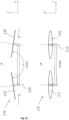
- Reference is made to
Figs. 1 and1a .Fig. 1 is a schematic perspective view of priorart quadcopter drone 10. That is to say, this is a drone with an array of four rotors (15, 20, 25 and 30), each of which has an axis of movement (35) that is perpendicular to the X-Z plane, wherein the rotors have multiple blades (in the illustrated example - two blades per rotor), which also enables modifying their pitch angles (α).Fig. 1a depict schematic front and side views (see the initial axis) ofdrone 10, as well as a schematic front and side view (in broken lines) of drone '10, which is also a prior art drone. In drone '10, as opposed todrone 10, the axis of movement of each of its rotors ('35) are not perpendicular in their orientation to the plane of flight (X-Z), as indrone 10, but all slightly tilt towards the center of the drone towards one point (to improve drone '10 stability), while creating two convergence angles (seeFig. 1a - β as the first angle projection in the front view and ϕ as the second angle projection in the side view). - In drones, such as
quadcopter 10 and '10, rising in altitude is achieved by acceleration of all four rotors simultaneously, and altitude is reduced by slowing the rotation of all the rotors. Control of flight movements (the pitch, roll, and yaw movements) is generally achieved by modifying the relative speeds of the different rotor blades. - In a four-rotor array drone, such as
quadcopters 10 and '10, two rotors are positioned diagonally to each other, rotating in one direction, while the other two are rotating in the opposite direction (see directions of the arrow in the figure). That is to say, two rotors rotate clockwise and two counterclockwise (in a way that resets the reaction torque), which may cause the drone to rotate (yaw), and there is no need to invest energy in preventing its yawing. In such a configuration, it is easy to control the roll or pitch planes. Increasing the speed of two rotors on one side and slowing down the other two rotors on the other side will cause rolling or pitching (depending on the nature of the pairs of rotors). In other words, the speed of two rotors on the same side will be increased to create a rolling motion. To create a pitching motion, the speed of the two front rotors will be increased to lift the drone's nose, or the two rear rotors in order to lower the drone's nose. - In other words, the movement of the drone is controlled only by the differences in the rotation speed of the drone's blades. At the same time, in the illustrated example, as this involves quadcopter drones, which as stated enable modifying the pitch angles (α) of the rotor blades, angle modification can also be used for maneuvering the drone in all planes of flight.
- However, the skilled person is aware that such drones, and not only the type that enables modifying the pitch angle (α) of the rotor blades, do not produce a rapid yaw movement from the time such a maneuver is sought. Maneuvering such drones on the yaw plane is relatively slow and unwieldy, as it is not enough to modify the pitch angle of the rotor blades to produce the torque needed to perform a quick maneuver in the yaw plane. An attempt to yaw such a drone only by modifying the pitch angles of the rotor blades calls for considerably increasing the pitch angle to induce a high drag that will produce the torque needed for rapid yawing. The formation of a high drag impairs flight performances, poses a risk of stalling, and requires lowering the speed of the blades (lowering the RPM).
- Moreover, maneuvering a quadcopter drone by increasing the speed of two rotors on one side and slowing down two rotors on the other side naturally involves, as previously noted, having means for monitoring and controlling the rotation speeds of all the rotors in the array (in other words, the need to monitor and control the RPM of the rotors), in a way that calls for installing multiple electric engines that require a power source (battery) or that have an internal combustion engine (gasoline-powered engine), (which could be installed as part of a hybrid propulsion system - an internal combustion engine (gasoline-powered) with an electric engine for backup), which is connected to the reduction/increase gears of each of the rotors. These are clumsy and cumbersome measures (battery, speed reduction/increase gears), which weigh down on the drone and reduce the effective payload it can carry.
- It should also be borne in mind that the requirements for carrying the effective weight (payloads such as electro-optic payloads, armaments, etc.) over a long flight time pose ever-increasing challenges for drone designers. Flying with a heavy weight and over a long flight time generally leans towards preferring the use of an internal combustion gasoline-powered engine that is considered economical and efficient. However, as noted, the gasoline-powered engine does not allow for conveniently monitoring and controlling engine revolutions per minute (RPM), but with additional rather considerable weight (the required transmissions).
- Therefore, when it comes to improving maneuverability, the solution of propelling the array of rotors by a gasoline engine with a constant RPM combined with the ability to modify the rotor blades' pitch angles (α) is not sufficient, since, as stated, it is not enough to change the rotor blades' pitch angles to produce the torque needed to perform a quick maneuver in the yaw plane.
- Thus, prior to the date of the current invention, there was no effective solution to enable a multi-blade drone, such as a quadcopter, to make use of the preferred gasoline engine (by itself or in a hybrid system with one or more electric engine(s)) while enhancing the drone's yaw maneuverability.
- Quadcopters and aerial vehicles represenative of the state of the art are known from the documents
US2002/104922A1 ,US9296477B1 CN204895843U ,CN202244078U andEP3098161A1 . - The invention, which is the subject of the Patent Application, addresses the challenges described above.
- In one aspect, the invention is embodied in a quadcopter drone in accordance with
claim 1. - In another aspect, the invention is embodied in a method for providing improved yaw maneuverability of a quadcopter drone in accordance with claim 4. The method could comprise the additional stage of maneuvering the aerial vehicle to yaw by increasing the pitch angle (α) of the blades of diagonally opposite pair of rotors, each from another pair of the symmetrically tilted pairs of rotors, and reducing the pitch angle (α) of the remaining rotor blades that are also diagonally opposite each other, each from a different pair of the symmetrically tilted pairs of rotors.
- In a preferred embodiment of the invention, the quadcopter drone has a propulsion system that comprises an internal combustion engine (gasoline-powered), and when the said method is implemented, it enables the drone to maneuver in the yaw plane without modifying the speed of the blades (maintaining a constant RPM).
- In yet an additional aspect, the invention is implementable in a quadcopter drone in accordance with claim 6.
- Other aspects, additional embodiments and advantages of the drone and the flight method implemented in its operation will be described below. It should be borne in mind that the configurations described below may be combined with other configurations in different ways, which are at least consistent with one of the principles of the invention described below, and the terminology used here should not be construed as limiting in any way.
- Different aspects of at least one embodiment of the invention will be described below, with reference to the accompanying figures (while no scale should be attributed to them). The figures are presented for illustrative purposes only and for facilitating an understanding of the different aspects of the invention and the possible embodiments for its actual utilization. The figures are part of the description, but should not be construed as limiting the invention in any way. In the figures, an identical or similar element that is visually depicted in several figures could be tagged by uniform numbering. For clarity, not every element was tagged in each of the figures. In the following figures:
-
Figs. 1 and1a are as stated (respectively) a schematic perspective view of a prior art quadcopter drone as well as schematic front and side views of said drone (as well as a prior art drone where the axis of movement of each of its rotors all slightly tilt toward the center of the drone). -
Figs. 2 and2a are (respectively) a schematic perspective view of one example of a quadcopter drone according to the invention having improved maneuverability in the yaw plane, as well as front and side schematic views of said drone. -
Figs. 3 and3a ;4 and4a ; and5 and5a are schematic perspective views and front and side schematic views of three other embodiments of quadcopter drones according to the invention, which, like the example drone illustrated inFigs. 2 and2a , also structurally embodies the distinct feature of the invention (although in different geometries), in a manner that gives them, as aforesaid, improved maneuverability in the yaw plane. -
Figs. 6 and7 (respectively) depicts a perspective view of a quadcopter drone that structurally embodies the geometrical configuration of the invention, as schematically illustrated and by way of example only inFig. 2 , and an "exploded" view of its elements. -
Figs. 8 and8a are (respectively) a schematic perspective view of drone where the axis of movement of each of its rotors all slightly tilt toward the center of the drone but wherein the improved yaw maneuverability of the aerial vehicle in accordance with the invention, is achieved by providing the aerial vehicle with one geometrical dimension between its forward pair of rotors and rearward pair of rotors and a second different dimension between the rotors of each of said pairs, and a schematic front and side views of said drone . - Various devices and elements will be described below strictly for the purpose of giving an example of embodiment of the claimed invention. The embodiment described below does not limit the claimed invention, and the latter may also apply to devices and methods that differ from those described below. The claimed invention does not have to include all aspects of devices, elements and methods to be described below, and is not strictly limited to those that exist in all the embodiments described below. For the sake of integrity, it should be noted that the set of claims on the invention may be revised by way of amendment and/or by filing a divisional application. The skilled person will also understand that, for the sake of clarity, the embodiments are described without inundating the description with elements, methods and processes that are already considered to be common knowledge in the field, and in any case no tagged reference was provided to them in the figures.
- Reference is made to
Figs. 2 and2a .Fig. 2 is a schematic perspective view of one example ofquadcopter drone 210 according to the invention, which, as explained below, has improved maneuverability in the yaw plane over the prior art (see and compare, for example, drones 10 and '10, as described above in reference toFigs. 1 and1a ).Fig. 2a shows schematic front and side views ofdrone 210. - A prominent feature of
drone 210 is that the axis of movement (235) of each of the four rotors - 215, 220, 225 and 230 installed therein tilt from the outset in a symmetrical configuration in relation to x-y (yaw) plane, so that each pair of axis converge towards another point on the same level along the drone's longitudinal axis plane (in the illustrated example - along x-z plane), in creating a γ angle between the yaw planes of the rotor blades that is less than 180°. - As mentioned above in the "Background of the Invention" chapter, it is known that there are quadcopter drones in which the axis and rotors of their engines tilt towards the center of the drone in order to increase the drone's stability (the tilt improves the drone's stability at the expense of pitch and roll maneuverability) (see
Fig. 1a for drone '10). However, in contrast indrone 210, this is not a case where all the axis of movement tilt towards the center of the drone, but a symmetrical tilt of pairs of axis towards different points on the same level, along the longitudinal axis of the drone (see the illustrated example - a tilt towards plane x-z). - Another feature of
drone 210 is that it is a type of drone that enables modifying the pitch angle (α) of its rotor blades. - The symmetrical tilt of the axis of movement of the pairs of rotors in
drone 210, which we pointed to earlier, in combination with the ability to dynamically modify the pitch angles of the blades of each of the rotor, enables producing torques in the (x-y) yaw plane, which givedrone 210 improved yaw maneuverability, without having to adjust the rotors' rotation speed (in other words - while maintaining a constant RPM). - The symmetrical tilt of the axis of movement of the pairs of rotors generates side forces (F) that contribute to and increase the relative small torque due to the drag, which is usually generated by the modification of the pitch angle of the blades, in a way that provide the drone according to the invention, improved maneuverability in the yaw plane.
- Thus, for example (see
Fig. 2 ), the symmetrical tilt of the axis of movement of the pairs of rotors, which are built into the drone according to the invention, regularly generate side forces (F). At the same time, when increasing the pitch angle (α) ofrotor blades rotor blades 220 and 240, this produces a torque that together with side forces F1 and F4 (which will increase due to increasing of the pitch angle as stated) will maneuverdrone 20 to yaw in x-y plane in the direction of arrow 250 (clockwise). - At the same time and as previously noted, the improved maneuverability in the yaw plane of the drone according to the invention is achieved even without having to modify the relative speeds of the rotors. Therefore, a drone according to the invention could be fitted with a propulsion system that is based on an internal combustion engine (gasoline-powered), which as mentioned in the "Background of the Invention" chapter, is preferred for achieving long flight time and carrying a relatively heavy effective weight (payload).
- The skilled person will understand that the tilt of the pairs of rotors, so that each pair of axis converge towards different points on the same level in the drone's longitudinal axis plane (x-z plane according to the illustrated example), while creating a γ angle between the rotation planes of the blades, somewhat impairs the lifting performances of the drone in which the invention will be implemented (and therefore shortens its flight time). However, it was found that in order to achieve the improved maneuvering advantage in the yaw plane (and the advantage of the ability to fly the drone by means of an internal combustion engine (gasoline-powered) at a constant blade speed (constant RPM)), it is enough to slightly tilt the rotors' axis so that the γ angle of the drone according to the invention will be 1400 <γ < 1800, without significantly impairing the drone's performances (as dependent of course on other rather familiar design considerations, such as engine power, drone geometry (e.g. - distance of the rotors from the drone's longitudinal axis, etc.). At most, and given the advantage of propulsion at constant blade speed, the constant speed (RPM) may be increased to compensate for the loss of lift performances.
- The skilled person will also understand that in the said embodiment of the tilt of the axis of the pairs of rotors, so that each pair of axis converge towards different points on the same level along the drone's longitudinal axis plane (x-z plane according to the illustrated example), in creating a γ angle between the rotation planes of the rotor blades, the invention may also be applied to drones having a hybrid propulsion system (drones that combine an internal combustion engine (gasoline-powered) with a backup electric engine).
- The skilled person will also understand that in the said aspect of the tilt of the rotors' axis, so that each pair of axis converge towards different points on the same level along the drone's longitudinal axis plane (x-z plane according to the illustrated example), in creating a γ angle between the yaw planes of the rotor blades, the invention may also be applied not only in quadcopter drones (which by definition comprise an array of four rotors), such as
drone 210, but also in other multirotor drones (e.g. drones having arrays of 6, 8, 10 or 12 rotors). - Furthermore, according to the illustrated example, the tilt of the pairs of rotors, so that each pair of axis converge towards different points on the same level along the drone's longitudinal axis plane, takes place on the x-z plane in the upward direction, but the skilled person will understand that the tilt of these pair of axis, according to the invention, could be also applied on the same plane also downwards or on other planes of the drone (upward or downward).
- Reference is made to
Figs. 3 and3a ;4 and4a ; And5 and5a .Figs. 3 and3a ;4 and4a ; and5 and5a are side views of three other configurations of quadcopter drones according to the invention (respectively) - 310, 410 and 510, in which, likedrone 210 that we pointed to previously (in reference toFig. 2 ), the distinct feature of the invention is also implemented in the structure of these drones, i.e. the symmetrical tilt of the axis of movement of pairs of rotors, whereby each pair of axis converges towards different points on the same level along the drone's longitudinal axis plane. However, unlikedrone 210, indrones Figs. 1 ,2 and2a ). - In
drone 310, which is illustrated inFigs. 3 and3a , the axis of movement (335) of the pairs of rotors (315, 320, 325, 330) are tilted outward and converge downward (as opposed to the axis of movement of the pairs of rotors ofdrone 210, which tilt inward and converge upward). Indrone 410 illustrated inFigs. 4 and4a , the axis of movement (435) of the pairs of rotors are tilted to create a γ angle between the rotation planes of pair ofrotors rotors drone 510, illustrated inFigs. 5 and5a , the axis of movement (535) of pairs of rotors tilt outward and converge downward to create a γ angle between the yaw planes of pair ofrotors rotors 515 and 525 (while in addition to and similar todrone 410, they converge towards another longitudinal axis plane of the drone (to y-z plane as opposed to the x-z plane to which the pairs of rotors axis converged in drone 210). - The skilled person will understand that the symmetrical tilts of the axis of movement of pairs of rotors, as illustrated in
drones drone 210, improved yaw maneuverability, without having to adjust the rotors' rotation speed (in other words - while maintaining a constant RPM). All that is needed fordrones - Reference is made to
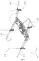
Figs. 6 and7 .Figs. 6 and7 (respectively) show a perspective view ofquadcopter drone 610, which structurally embodies a specific geometrical configuration of the invention, as described above for drone 210 (in reference toFigs. 2 and2a that show a schematic illustration ofdrone 210 by way of example only); and an "exploded" view depicting the elements ofdrone 610. - As to be described below in reference to the figures,
drone 610 is a quadcopter having a hybrid propulsion system (internal combustion engine fitted alongside an electric engine to be operated as a backup should one of them fail) and enables modifying the pitch angle (α) of the blades of the four rotors - 615, 620, 625 and 630 fitted therein (each having a two-blade configuration). Indrone 610, the propulsion system propels all four rotors at an equal speed at a given time (i.e. a drone having a constant RPM). - As previously noted,
drone 610 structurally embodies a specific geometric configuration of the invention, as described above for drone 210 - from the time it is assembled, the axis of movement (635) of each of the four rotors are symmetrically tilted in relation to the x-y yaw plane, so that each pair of axis converge towards different points on the same level along a longitudinal axis plane of the drone (x-z plane), while creating a γ angle between the rotation planes of the rotor blades that is less than 180°. -
Drone 610 is comprised ofchassis element 752, which may be manufactured, for example, from aluminum or composite materials.Main drive shaft 755 serves to shift drive frompropulsion system 758, on either side, to the rotors. The propulsion system ofdrone 610 is as stated a hybrid system, and is comprised ofelectric engine 761, which is fitted in tandem configuration with and parallel to internal combustion engine 764 (according to the illustrated example, in a tandem configuration - side by side - at the center of the drone). In the case of a failure,electric engine 761 may be actuated byclutch assembly 777, which enables propelling the main drive shaft by the electric engine in the event of a malfunction/failure of the internal combustion engine (and vice versa).Clutch assembly 777 may also include reduction gears to adjust the number of revolutions of the propulsion system as required.Shelf 780 is also formed onchassis element 752. The shelf serves for mounting the drone's avionic assemblies on it (assemblies that are not illustrated, but usually include communication, navigation, autopilot and command systems).Landing gear 783 is fitted under the chassis element. The skilled person will understand that the chassis element may also be made with reinforcement rods (not illustrated) extending from it towards each of the rotors. The propulsion generated frompropulsion system 758 is transferred throughmain drive shaft 755, simultaneously to twogear assemblies - According to the illustrated example, the angular tilt occurs in the gear assemblies in a manner that leads to tilting the axis of movement (635) of each of the four rotors in a symmetrical configuration in relation to the x-y yaw plane, so that each pair of axis converge towards different points on the same level along a longitudinal axis plane of the drone (x-z plane), while creating a γ angle between the rotation planes of the rotor blades that is less than 180°. The skilled person will understand that this is only an example, and that the tilt sought can also be produced by other means, e.g. by installing gears that enable such tilting near each of the rotors.
- The propulsion from the gear assemblies towards each of the rotors is transferred by
driveshaft bars Driveshaft bar 792 is connected to gear assembly L 804 (propelling rotor 615),driveshaft bar 795 is connected to gear assembly L 807 (propelling rotor 620),driveshaft bar 798 is connected to gear assembly L 811 (propelling rotor 625), anddriveshaft bar 801 is connected to gear assembly L 814 (propelling rotor 630). - The gear assemblies are each formed in an L configuration as a gear implementing conical cogwheels in a way that enable angularly tilting the direction of the propulsion. According to the illustrated example, the angular tilt achieved by gear assembly L is 900 (since the angular tilt needed to obtain a γ angle between the rotation planes of the blades is already produced by the T gear assemblies (786 and 789)). However, the skilled person will understand that also the L gear assemblies may be formed as gears, for example, of conical cogwheels, in a way that enable achieving the sought tilt required for obtaining the γ angle, in whole or in part, at this site.
- L gear assemblies each also comprise an assembly for actuating the modification of the pitch angle (α) of the rotor blades to which it is connected. The skilled person is familiar with a range of such actuating assemblies, which could be based, for example, on a tiny electric servo engine with a transmission that translates the engine's movement into opposite linear movements of pairs of arms that are connected to the rotor blades and modify their pitch angle in a pivotal movement. Fitting each of the rotors as illustrated, with a pitch angle modification actuator enables as said, dynamically, during flight, modification of the pitch angle, for each specific rotor, of said specific rotor blades.
- As noted,
drone 610 is only an example of how the invention is implemented. A drone such asdrone 610 has already been tested and proven to have improved efficiency in yaw plane maneuvering. The γ angle between the rotation planes of the test drone designed to be within the range according to the invention - 1730 in the test drone. The test drone was fitted with an electric engine, type AXI-F3A-53XX (2500W) and a two-stroke piston internal combustion engine type ZENOAH 26cc (2.5 HP). As stated, the test drone comprised of four two-blade rotors, each with a blade length of 330 mm. During its flight and in achieving the improved maneuverability, it was enough to exploit the possibility of modifying the blades pitch angle (α) within an angle range of 0-60 (wherein the pitch angle modification (α) actuators allow for a much larger angular modification (-230- +350). In other words, operating the test drone according to the invention at a constant RPM merely required a relatively slight modification of the blades' pitch angle, in a manner that maintained a relatively low drag and did not affect their efficiency in order to achieve improved yaw performance (as a result of the contribution of side forces (F) achieved according to the invention, seeFig. 2 and the explanations provided above in this context). The dimensions of the test drone were 90 cm * 90 cm (distance between the rotors blades rotational planes axis). The takeoff weight was 11 kg. The test drone carried a 3 kg payload in a flight mission profile for about three hours, and was designed for flight at altitudes of up to 12,000 feet at an average cruising speed of 65 knots, while demonstrating improved yaw maneuverability as stated, in light of the implementation of the invention in the drone' structure. - Therefore,
drone 610 as described above in relation toFigs. 6 and7 is a practical and proven example of the application of the invention, but any skilled person will understand that this is only an example, and the invention could also be applied in other geometrical configurations (see, for example, the different geometries ofdrones Figs. 3 and3a ;4 and4a ; and5 and5a ). - Moreover, the skilled person will understand that this as stated is only an example also with respect to the type of drone (quadcopter in this specific case) and with respect of the various structural components used - propulsion systems, transmissions/gears, blades, etc. as well as commercially known components and assemblies.
- In fact, in view of the description provided above in referring to the accompanying figures, the skilled person will understand that the invention is also embodied in a general method. A general method applicable in a wide range of multi-blade drones which provide the ability to modify the pitch angle of the rotor blades fitted therein (α) for providing those drones with improved yaw maneuverability and while enabling easy installation of a clearly preferred propulsion system - an internal combustion engine (gasoline-powered). This is achieved in light of achieving the improved maneuverability also at a constant RPM (therefore, avoiding the need to install the drone with unwieldy reduction gears).
- A method that includes the stage of providing the axis of movement (235, 335, 435, 5353, 635) of each of the rotors installed therein, wherein they are tilted in a symmetrical configuration in relation to the aerial vehicle's yaw plane (x-y) so that each pair of axis converge towards another point on the same level along a longitudinal axis plane of the drone while creating a γ angle between the rotation planes of the blades of each pair, which is less than 180° but greater than 1400.
- In the second state, the method could include maneuvering the aerial vehicle to yaw by increasing the pitch angle (α) of the blades of diagonally opposite pair of rotors, each from another pair of said symmetrically tilted pairs of rotors, and reducing the pitch angle (α) of the blades of the remaining rotors that are also diagonally opposite each other, each from a different pair of said symmetrically tilted two pairs of rotors.
- Furthermore, in light of the description given above with reference to the accompanying figures, the skilled person will understand that the invention can be applied not only to unmanned multi-blade aerial vehicles (drones according to the examples provided here), but also to manned multi-blade aircraft, (i.e. that include a team such as a pilot or even medic - in the event of a multi-blade aircraft that is flown by remote control, but serves for rescuing an injured person and treating him in flight).
- In addition, in light of the description provided hereinabove while referring to the accompanying figures, a skilled person will also understand that generating side forces (F) that contribute to and increase the relative small torque due to the drag, which is usually generated by the modification of the pitch angle of the aerial vehicle rotors blades, in a way that provide the aerial vehicle according to the invention, with improved maneuverability in the yaw plane, is also achievable in the design of multi-blade aerial vehicle of the type wherein the axis of each of its rotors are all tilted towards the center of the aerial vehicle (see for example quadcopter drone '10 as depicted in
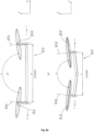
figs 1 and1a and described hereinabove in the "Background of the Invention" chapter). - Reference is made to
Figs. 8 and8a .Figs 8 and8a are (respectively) a schematic perspective view ofquadcopter drone 810 and a schematic front and side views of said drone. Similarly to drone '10, the axis of movement (835) of each ofdrone 810 four rotors - 815, 820, 825, and 830, all slightly tilt toward the center of the drone. Another feature ofdrone 810 is that it is a type of drone that enables modifying the pitch angle (α) of its rotor blades. The improved yaw maneuverability ofdrone 810 is achieved by providingdrone 810 with one geometrical dimension (x) between its forward pair of rotors - 815, 820 and its rearward pair of rotors - 825, 830. and a second different geometrical dimension (y) between the rotors of each of said pairs. - A skilled person will understand that by providing
drone 810 with such geometrically different dimensions (x, y) will also generate side forces (F) that contribute to and increase the relative small torque due to the drag, which is usually generated by the modification of the pitch angle (α) ofdrone 810 rotors blades, in a way that providedrone 810 according to the invention, with improved maneuverability in the yaw plane. - The Patent Applicant provided the above description in referring to the accompanying figures for illustrative purposes only.
Claims (7)
- A quadcopter drone (210), that enables modifying the pitch angle (α) of its rotors (215, 220, 225, 230) blades,
wherein-
the axis of movement (235) of at least two pairs of the quadcopter drone's rotors are tilted in a symmetrical configuration in relation to the quadcopter drone's yaw plane, so that each pair converges towards another point on the same level along a longitudinal axis plane of the quadcopter drone while creating an angle (γ) between the rotation planes of the rotors of each pair, which is less than 180° and greater than 140°;wherein said drone enables maneuvering in its yaw plane, but by modifying the pitch angles (α) of its rotors blades, without changing the rotational speed of said blades;wherein the axis of movement of the rotors are distanced from each other such that there is no overlap of a rotor blade rotation circles of any of the four rotors;wherein each pair of rotors consists of one rotor rotating clockwise and one rotor rotating counter-clockwise and diagonally opposite rotors rotating in the same direction. - A quadcopter drone according to claim 1, wherein -
the propulsion system of said drone comprises an internal combustion (engine 764). - A quadcopter drone according to claim 1, wherein -
the propulsion system of said drone is a hybrid system, and is comprised of an internal combustion engine (764) in tandem with an electric engine (761). - A method for providing improved maneuverability in the yaw plane of a quadcopter drone (210) that enables modifying the pitch (α) of its rotors (215, 220, 225, 230) blades, which include the stage of - providing the axis of movement (235) of at least two pairs of the quadcopter drone's rotors, when they are tilted in a symmetrical configuration in relation to the quadcopter drone's yaw plane so that they converge in their direction, each pair towards another point on the same level along a longitudinal axis plane of the drone, while creating an angle (γ) between the rotation planes of the rotor blades of each pair, which is less than 180° but greater than 140°, wherein the axis of movement of the rotors are distanced from each other such that there is no overlap of rotor blade rotation circles of any of the four rotors, wherein each pair of rotors consists of one rotor rotating clockwise and one rotor rotating counter-clockwise and diagonally opposite rotors rotating in the same direction.
- The method of Claim 4, wherein the method comprises in addition, the stage of - maneuvering the quadcopter drone to yaw by increasing the pitch angle (α) of diagonally opposite pair of rotor blades, each from another pair of said symmetrically tilted two pairs of rotors, and reducing the pitch angle (α) of the blades of the remaining pair of rotors that are also diagonally opposite each other, each from a different pair of said symmetrically tilted two pairs of rotors.
- A quadcopter drone (810), wherein the axis of movement (835) of each of the quadcopter drone's rotors (815, 820, 825, 830) tilts toward the center of the quadcopter drone and said quadcopter drone is of the type that enables modifying the pitch angle (α) of its rotors blades, wherein-said quadcopter drone is formed with one geometrical dimension (x) between its forward rotors and its rearward rotors and a second different geometrical dimension (y) between the rotors of each of forward and rearward rotors,wherein the axis of movement of the rotors are distanced from each other such that there is no overlap of rotor blade rotation circles of any of the four rotors, wherein each pair of rotors consists of one rotor rotating clockwise and one rotor rotating counter-clockwise and diagonally opposite rotors rotate in the same direction.
- A quadcopter drone according to claim 6 wherein -
said one geometrical dimension (x) is between its forward pair of rotors and its rearward pair of rotors and said second different geometrical dimension (y) is between the rotors of each of said forward and rearward pair of rotors.
Applications Claiming Priority (3)
| Application Number | Priority Date | Filing Date | Title |
|---|---|---|---|
| US201862654446P | 2018-04-08 | 2018-04-08 | |
| IL261236A IL261236B2 (en) | 2018-08-19 | 2018-08-19 | Maneuverability improved airborne vehicle and a method implemented for this purpose |
| PCT/IL2019/050394 WO2019198071A1 (en) | 2018-04-08 | 2019-04-07 | Improved maneuverability aerial vehicle and a method implemented for this purpose |
Publications (3)
| Publication Number | Publication Date |
|---|---|
| EP3774530A1 EP3774530A1 (en) | 2021-02-17 |
| EP3774530A4 EP3774530A4 (en) | 2021-12-22 |
| EP3774530B1 true EP3774530B1 (en) | 2023-10-04 |
Family
ID=65656161
Family Applications (1)
| Application Number | Title | Priority Date | Filing Date |
|---|---|---|---|
| EP19784203.2A Active EP3774530B1 (en) | 2018-04-08 | 2019-04-07 | Improved maneuverability aerial vehicle and a method implemented for this purpose |
Country Status (7)
| Country | Link |
|---|---|
| US (1) | US20210053675A1 (en) |
| EP (1) | EP3774530B1 (en) |
| CN (1) | CN111954619A (en) |
| ES (1) | ES2966080T3 (en) |
| FI (1) | FI3774530T3 (en) |
| IL (2) | IL261236B2 (en) |
| WO (1) | WO2019198071A1 (en) |
Families Citing this family (12)
| Publication number | Priority date | Publication date | Assignee | Title |
|---|---|---|---|---|
| CN109562828A (en) | 2016-06-03 | 2019-04-02 | 威罗门飞行公司 | VTOL (VTOL) lifting vehicle with complementary angled rotor |
| EP3729228A4 (en) * | 2019-03-12 | 2020-12-02 | SZ DJI Technology Co., Ltd. | Method and apparatus for detecting radar wave offset |
| US12074701B2 (en) * | 2020-05-14 | 2024-08-27 | Qualcomm Incorporated | Legacy control channel format support |
| KR102342808B1 (en) * | 2020-06-29 | 2021-12-24 | 이상현 | Method for controlling drone having multiple flying modes |
| KR102360641B1 (en) | 2020-06-29 | 2022-02-10 | 이상현 | Drone |
| US11840351B2 (en) * | 2021-04-05 | 2023-12-12 | Beta Air, Llc | Aircraft for self-neutralizing flight |
| WO2023051929A1 (en) * | 2021-09-30 | 2023-04-06 | Emagic Aircraft Gmbh | Electrically propelled aircraft |
| JP6979251B1 (en) * | 2021-10-07 | 2021-12-08 | 株式会社石川エナジーリサーチ | Flight equipment |
| EP4422975B1 (en) * | 2021-10-27 | 2026-03-04 | Textron Systems Corporation | Modular rotorcraft and system for air-delivered effects or sensor payloads |
| JP7789645B2 (en) * | 2022-09-09 | 2025-12-22 | 本田技研工業株式会社 | Thrust generator |
| EP4644274A1 (en) * | 2022-12-27 | 2025-11-05 | Kubota Corporation | Flying apparatus |
| US12404911B1 (en) | 2024-12-06 | 2025-09-02 | Samanth Mottera Srinivas | Turboshaft engine powered quadrotor drone |
Family Cites Families (25)
| Publication number | Priority date | Publication date | Assignee | Title |
|---|---|---|---|---|
| US5419514A (en) * | 1993-11-15 | 1995-05-30 | Duncan; Terry A. | VTOL aircraft control method |
| US20020104922A1 (en) * | 2000-12-08 | 2002-08-08 | Mikio Nakamura | Vertical takeoff and landing aircraft with multiple rotors |
| GB2462452B (en) * | 2008-08-08 | 2011-02-02 | Univ Manchester | A rotary wing vehicle |
| US20120209456A1 (en) * | 2011-02-15 | 2012-08-16 | Government Of The United States, As Represented By The Secretary Of The Air Force | Parallel Hybrid-Electric Propulsion Systems for Unmanned Aircraft |
| CN202244078U (en) * | 2011-07-29 | 2012-05-30 | 深圳市大疆创新科技有限公司 | Multi-rotor UAV |
| US9102326B2 (en) * | 2012-03-05 | 2015-08-11 | Embry-Riddle Aeronautical University, Inc. | Hybrid assembly for an aircraft |
| DE102012209803A1 (en) * | 2012-06-12 | 2013-12-12 | Siemens Aktiengesellschaft | Method for providing a predetermined drive characteristic in an aircraft and associated drive device |
| DE202013012547U1 (en) * | 2012-11-15 | 2017-07-03 | SZ DJI Technology Co., Ltd. | Unmanned aerial vehicle with multiple rotors |
| TW201536632A (en) * | 2014-03-20 | 2015-10-01 | Avix Technology Inc | Dual-motor pitch-variable multi-rotor flight vehicle |
| CN106573676A (en) * | 2014-06-03 | 2017-04-19 | 希菲作品公司 | Fixed rotor thrust vectoring |
| US9296477B1 (en) * | 2014-07-21 | 2016-03-29 | Glenn Coburn | Multi-rotor helicopter |
| EP2990332A1 (en) * | 2014-08-19 | 2016-03-02 | Tau Emerald Rotors Inc. | Controlling rotary wing aircraft |
| CN104494820A (en) * | 2014-12-18 | 2015-04-08 | 国家电网公司 | Oil-driven four-rotor-wing unmanned aerial vehicle |
| CN204895843U (en) * | 2015-04-30 | 2015-12-23 | 何春旺 | Multiaxis aircraft |
| DE102015006511A1 (en) * | 2015-05-26 | 2016-12-01 | Airbus Defence and Space GmbH | Vertical launching aircraft |
| US9764829B1 (en) * | 2015-06-09 | 2017-09-19 | Amazon Technologies, Inc. | Multirotor aircraft with enhanced yaw control |
| US10805540B2 (en) * | 2015-10-28 | 2020-10-13 | Vantage Robotics, Llc | Quadcopter with pitched propeller configuration |
| EP3184425B1 (en) * | 2015-12-21 | 2018-09-12 | AIRBUS HELICOPTERS DEUTSCHLAND GmbH | Multirotor aircraft |
| CN109562828A (en) * | 2016-06-03 | 2019-04-02 | 威罗门飞行公司 | VTOL (VTOL) lifting vehicle with complementary angled rotor |
| JP6557883B2 (en) * | 2016-08-22 | 2019-08-14 | 株式会社Soken | Flight equipment |
| GB2555439A (en) * | 2016-10-27 | 2018-05-02 | Mono Aerospace Ip Ltd | Vertical take-off and landing aircraft and control method |
| CN206155785U (en) * | 2016-11-08 | 2017-05-10 | 深圳市大疆创新科技有限公司 | Motor and have unmanned aerial vehicle of this motor |
| CN106516131A (en) * | 2017-01-12 | 2017-03-22 | 佛山市海科云筹信息技术有限公司 | Frame structure and flying device using frame structure |
| PH12020551665B1 (en) * | 2018-04-24 | 2024-01-31 | Thomas W Melcher | Electric vertical takeoff and landing aircraft |
| US20200393851A1 (en) * | 2019-06-12 | 2020-12-17 | Bell Textron Inc. | Multi-rotor high performance descent method and system |
-
2018
- 2018-08-19 IL IL261236A patent/IL261236B2/en unknown
-
2019
- 2019-04-07 ES ES19784203T patent/ES2966080T3/en active Active
- 2019-04-07 US US17/045,746 patent/US20210053675A1/en active Pending
- 2019-04-07 EP EP19784203.2A patent/EP3774530B1/en active Active
- 2019-04-07 FI FIEP19784203.2T patent/FI3774530T3/en active
- 2019-04-07 IL IL277707A patent/IL277707B2/en unknown
- 2019-04-07 WO PCT/IL2019/050394 patent/WO2019198071A1/en not_active Ceased
- 2019-04-07 CN CN201980024434.6A patent/CN111954619A/en active Pending
Also Published As
| Publication number | Publication date |
|---|---|
| EP3774530A1 (en) | 2021-02-17 |
| IL261236A (en) | 2020-02-27 |
| US20210053675A1 (en) | 2021-02-25 |
| WO2019198071A1 (en) | 2019-10-17 |
| IL277707B2 (en) | 2025-02-01 |
| IL261236B (en) | 2022-12-01 |
| EP3774530A4 (en) | 2021-12-22 |
| CN111954619A (en) | 2020-11-17 |
| IL277707A (en) | 2020-11-30 |
| BR112020020400A2 (en) | 2021-01-12 |
| IL277707B1 (en) | 2024-10-01 |
| IL261236B2 (en) | 2023-04-01 |
| FI3774530T3 (en) | 2023-11-28 |
| ES2966080T3 (en) | 2024-04-18 |
Similar Documents
| Publication | Publication Date | Title |
|---|---|---|
| EP3774530B1 (en) | Improved maneuverability aerial vehicle and a method implemented for this purpose | |
| EP3725680B1 (en) | Multimodal unmanned aerial systems having tiltable wings | |
| US11485488B1 (en) | Vertical take-off and landing aircraft with rotor thrust yaw control | |
| EP3000722B1 (en) | Aircraft | |
| EP3121117B1 (en) | Control system and strategy for tail sitter | |
| RU2670356C2 (en) | Aircraft capable of vertical take-off | |
| US8979015B2 (en) | Anti-torque device with longitudinal thrust for a rotorcraft | |
| US7665688B2 (en) | Convertible aerial vehicle with contra-rotating wing/rotors and twin tilting wing and propeller units | |
| US11738862B2 (en) | Fail-operational vtol aircraft | |
| EP2991897B1 (en) | Vertical takeoff and landing (vtol) air vehicle | |
| US9120560B1 (en) | Vertical take-off and landing aircraft | |
| US11433093B2 (en) | Compact gyroplane employing torque compensated main rotor and hybrid power train | |
| EP3972896B1 (en) | Vertical Take-Off and Landing (VTOL) Aircraft with Fixed, Forward-Tilted Rotors to Simulate the Dynamics of Fixed Wings | |
| US20160244159A1 (en) | Controlled Take-Off And Flight System Using Thrust Differentials | |
| US10836482B2 (en) | Rotorcraft having a rotary wing and at least two propellers, and a method applied by the rotorcraft | |
| JP7037826B2 (en) | Propeller type flying object | |
| US20210229802A1 (en) | Fail-operational vtol aircraft | |
| US9139298B2 (en) | Rotorcraft control system for rotorcraft with two or more rotor systems | |
| EP3730404A1 (en) | Vertical take-off and landing aircraft and related control method | |
| US11964759B2 (en) | Convertiplane | |
| US11794886B2 (en) | Hybrid rotorcraft having at least one pusher or puller propeller, and an associated piloting method | |
| WO2024196414A1 (en) | Compact gyroplane employing torque compensated main rotor and hybrid power train | |
| CN114802711A (en) | Unmanned aerial vehicle with single duct at tail part | |
| CN114987737A (en) | Tail active variable-pitch ducted propulsion unmanned aerial vehicle | |
| HK40040898A (en) | Improved maneuverability aerial vehicle and a method implemented for this purpose |
Legal Events
| Date | Code | Title | Description |
|---|---|---|---|
| STAA | Information on the status of an ep patent application or granted ep patent |
Free format text: STATUS: THE INTERNATIONAL PUBLICATION HAS BEEN MADE |
|
| PUAI | Public reference made under article 153(3) epc to a published international application that has entered the european phase |
Free format text: ORIGINAL CODE: 0009012 |
|
| STAA | Information on the status of an ep patent application or granted ep patent |
Free format text: STATUS: REQUEST FOR EXAMINATION WAS MADE |
|
| 17P | Request for examination filed |
Effective date: 20200930 |
|
| AK | Designated contracting states |
Kind code of ref document: A1 Designated state(s): AL AT BE BG CH CY CZ DE DK EE ES FI FR GB GR HR HU IE IS IT LI LT LU LV MC MK MT NL NO PL PT RO RS SE SI SK SM TR |
|
| AX | Request for extension of the european patent |
Extension state: BA ME |
|
| DAV | Request for validation of the european patent (deleted) | ||
| DAX | Request for extension of the european patent (deleted) | ||
| A4 | Supplementary search report drawn up and despatched |
Effective date: 20211124 |
|
| RIC1 | Information provided on ipc code assigned before grant |
Ipc: B64C 39/02 20060101ALI20211118BHEP Ipc: B64D 27/02 20060101ALI20211118BHEP Ipc: B64C 39/00 20060101ALI20211118BHEP Ipc: B64C 27/08 20060101AFI20211118BHEP |
|
| GRAP | Despatch of communication of intention to grant a patent |
Free format text: ORIGINAL CODE: EPIDOSNIGR1 |
|
| STAA | Information on the status of an ep patent application or granted ep patent |
Free format text: STATUS: GRANT OF PATENT IS INTENDED |
|
| RIC1 | Information provided on ipc code assigned before grant |
Ipc: B64U 50/13 20230101ALI20230418BHEP Ipc: B64U 10/13 20230101ALI20230418BHEP Ipc: B64C 39/00 20060101ALI20230418BHEP Ipc: B64D 27/02 20060101ALI20230418BHEP Ipc: B64C 39/02 20060101ALI20230418BHEP Ipc: B64C 27/08 20060101AFI20230418BHEP |
|
| INTG | Intention to grant announced |
Effective date: 20230523 |
|
| GRAS | Grant fee paid |
Free format text: ORIGINAL CODE: EPIDOSNIGR3 |
|
| GRAA | (expected) grant |
Free format text: ORIGINAL CODE: 0009210 |
|
| STAA | Information on the status of an ep patent application or granted ep patent |
Free format text: STATUS: THE PATENT HAS BEEN GRANTED |
|
| AK | Designated contracting states |
Kind code of ref document: B1 Designated state(s): AL AT BE BG CH CY CZ DE DK EE ES FI FR GB GR HR HU IE IS IT LI LT LU LV MC MK MT NL NO PL PT RO RS SE SI SK SM TR |
|
| REG | Reference to a national code |
Ref country code: GB Ref legal event code: FG4D |
|
| REG | Reference to a national code |
Ref country code: CH Ref legal event code: EP |
|
| REG | Reference to a national code |
Ref country code: IE Ref legal event code: FG4D |
|
| REG | Reference to a national code |
Ref country code: DE Ref legal event code: R096 Ref document number: 602019038731 Country of ref document: DE |
|
| REG | Reference to a national code |
Ref country code: FI Ref legal event code: FGE |
|
| REG | Reference to a national code |
Ref country code: LT Ref legal event code: MG9D |
|
| REG | Reference to a national code |
Ref country code: GR Ref legal event code: EP Ref document number: 20230402502 Country of ref document: GR Effective date: 20240110 |
|
| REG | Reference to a national code |
Ref country code: NL Ref legal event code: MP Effective date: 20231004 |
|
| REG | Reference to a national code |
Ref country code: AT Ref legal event code: MK05 Ref document number: 1617526 Country of ref document: AT Kind code of ref document: T Effective date: 20231004 |
|
| PG25 | Lapsed in a contracting state [announced via postgrant information from national office to epo] |
Ref country code: NL Free format text: LAPSE BECAUSE OF FAILURE TO SUBMIT A TRANSLATION OF THE DESCRIPTION OR TO PAY THE FEE WITHIN THE PRESCRIBED TIME-LIMIT Effective date: 20231004 |
|
| PG25 | Lapsed in a contracting state [announced via postgrant information from national office to epo] |
Ref country code: IS Free format text: LAPSE BECAUSE OF FAILURE TO SUBMIT A TRANSLATION OF THE DESCRIPTION OR TO PAY THE FEE WITHIN THE PRESCRIBED TIME-LIMIT Effective date: 20240204 |
|
| PG25 | Lapsed in a contracting state [announced via postgrant information from national office to epo] |
Ref country code: LT Free format text: LAPSE BECAUSE OF FAILURE TO SUBMIT A TRANSLATION OF THE DESCRIPTION OR TO PAY THE FEE WITHIN THE PRESCRIBED TIME-LIMIT Effective date: 20231004 |
|
| REG | Reference to a national code |
Ref country code: ES Ref legal event code: FG2A Ref document number: 2966080 Country of ref document: ES Kind code of ref document: T3 Effective date: 20240418 |
|
| PG25 | Lapsed in a contracting state [announced via postgrant information from national office to epo] |
Ref country code: AT Free format text: LAPSE BECAUSE OF FAILURE TO SUBMIT A TRANSLATION OF THE DESCRIPTION OR TO PAY THE FEE WITHIN THE PRESCRIBED TIME-LIMIT Effective date: 20231004 |
|
| PG25 | Lapsed in a contracting state [announced via postgrant information from national office to epo] |
Ref country code: LT Free format text: LAPSE BECAUSE OF FAILURE TO SUBMIT A TRANSLATION OF THE DESCRIPTION OR TO PAY THE FEE WITHIN THE PRESCRIBED TIME-LIMIT Effective date: 20231004 Ref country code: IS Free format text: LAPSE BECAUSE OF FAILURE TO SUBMIT A TRANSLATION OF THE DESCRIPTION OR TO PAY THE FEE WITHIN THE PRESCRIBED TIME-LIMIT Effective date: 20240204 Ref country code: BG Free format text: LAPSE BECAUSE OF FAILURE TO SUBMIT A TRANSLATION OF THE DESCRIPTION OR TO PAY THE FEE WITHIN THE PRESCRIBED TIME-LIMIT Effective date: 20240104 Ref country code: AT Free format text: LAPSE BECAUSE OF FAILURE TO SUBMIT A TRANSLATION OF THE DESCRIPTION OR TO PAY THE FEE WITHIN THE PRESCRIBED TIME-LIMIT Effective date: 20231004 Ref country code: PT Free format text: LAPSE BECAUSE OF FAILURE TO SUBMIT A TRANSLATION OF THE DESCRIPTION OR TO PAY THE FEE WITHIN THE PRESCRIBED TIME-LIMIT Effective date: 20240205 |
|
| PG25 | Lapsed in a contracting state [announced via postgrant information from national office to epo] |
Ref country code: SE Free format text: LAPSE BECAUSE OF FAILURE TO SUBMIT A TRANSLATION OF THE DESCRIPTION OR TO PAY THE FEE WITHIN THE PRESCRIBED TIME-LIMIT Effective date: 20231004 Ref country code: RS Free format text: LAPSE BECAUSE OF FAILURE TO SUBMIT A TRANSLATION OF THE DESCRIPTION OR TO PAY THE FEE WITHIN THE PRESCRIBED TIME-LIMIT Effective date: 20231004 Ref country code: PL Free format text: LAPSE BECAUSE OF FAILURE TO SUBMIT A TRANSLATION OF THE DESCRIPTION OR TO PAY THE FEE WITHIN THE PRESCRIBED TIME-LIMIT Effective date: 20231004 Ref country code: NO Free format text: LAPSE BECAUSE OF FAILURE TO SUBMIT A TRANSLATION OF THE DESCRIPTION OR TO PAY THE FEE WITHIN THE PRESCRIBED TIME-LIMIT Effective date: 20240104 Ref country code: LV Free format text: LAPSE BECAUSE OF FAILURE TO SUBMIT A TRANSLATION OF THE DESCRIPTION OR TO PAY THE FEE WITHIN THE PRESCRIBED TIME-LIMIT Effective date: 20231004 Ref country code: HR Free format text: LAPSE BECAUSE OF FAILURE TO SUBMIT A TRANSLATION OF THE DESCRIPTION OR TO PAY THE FEE WITHIN THE PRESCRIBED TIME-LIMIT Effective date: 20231004 |
|
| REG | Reference to a national code |
Ref country code: DE Ref legal event code: R097 Ref document number: 602019038731 Country of ref document: DE |
|
| PG25 | Lapsed in a contracting state [announced via postgrant information from national office to epo] |
Ref country code: DK Free format text: LAPSE BECAUSE OF FAILURE TO SUBMIT A TRANSLATION OF THE DESCRIPTION OR TO PAY THE FEE WITHIN THE PRESCRIBED TIME-LIMIT Effective date: 20231004 |
|
| PG25 | Lapsed in a contracting state [announced via postgrant information from national office to epo] |
Ref country code: SK Free format text: LAPSE BECAUSE OF FAILURE TO SUBMIT A TRANSLATION OF THE DESCRIPTION OR TO PAY THE FEE WITHIN THE PRESCRIBED TIME-LIMIT Effective date: 20231004 |
|
| PG25 | Lapsed in a contracting state [announced via postgrant information from national office to epo] |
Ref country code: SM Free format text: LAPSE BECAUSE OF FAILURE TO SUBMIT A TRANSLATION OF THE DESCRIPTION OR TO PAY THE FEE WITHIN THE PRESCRIBED TIME-LIMIT Effective date: 20231004 Ref country code: SK Free format text: LAPSE BECAUSE OF FAILURE TO SUBMIT A TRANSLATION OF THE DESCRIPTION OR TO PAY THE FEE WITHIN THE PRESCRIBED TIME-LIMIT Effective date: 20231004 Ref country code: RO Free format text: LAPSE BECAUSE OF FAILURE TO SUBMIT A TRANSLATION OF THE DESCRIPTION OR TO PAY THE FEE WITHIN THE PRESCRIBED TIME-LIMIT Effective date: 20231004 Ref country code: EE Free format text: LAPSE BECAUSE OF FAILURE TO SUBMIT A TRANSLATION OF THE DESCRIPTION OR TO PAY THE FEE WITHIN THE PRESCRIBED TIME-LIMIT Effective date: 20231004 Ref country code: DK Free format text: LAPSE BECAUSE OF FAILURE TO SUBMIT A TRANSLATION OF THE DESCRIPTION OR TO PAY THE FEE WITHIN THE PRESCRIBED TIME-LIMIT Effective date: 20231004 |
|
| PLBE | No opposition filed within time limit |
Free format text: ORIGINAL CODE: 0009261 |
|
| STAA | Information on the status of an ep patent application or granted ep patent |
Free format text: STATUS: NO OPPOSITION FILED WITHIN TIME LIMIT |
|
| 26N | No opposition filed |
Effective date: 20240705 |
|
| REG | Reference to a national code |
Ref country code: DE Ref legal event code: R082 Ref document number: 602019038731 Country of ref document: DE Representative=s name: STRAUS, ALEXANDER, DIPL.-CHEM.UNIV. DR.PHIL., DE |
|
| PG25 | Lapsed in a contracting state [announced via postgrant information from national office to epo] |
Ref country code: SI Free format text: LAPSE BECAUSE OF FAILURE TO SUBMIT A TRANSLATION OF THE DESCRIPTION OR TO PAY THE FEE WITHIN THE PRESCRIBED TIME-LIMIT Effective date: 20231004 |
|
| PG25 | Lapsed in a contracting state [announced via postgrant information from national office to epo] |
Ref country code: SI Free format text: LAPSE BECAUSE OF FAILURE TO SUBMIT A TRANSLATION OF THE DESCRIPTION OR TO PAY THE FEE WITHIN THE PRESCRIBED TIME-LIMIT Effective date: 20231004 |
|
| PG25 | Lapsed in a contracting state [announced via postgrant information from national office to epo] |
Ref country code: MC Free format text: LAPSE BECAUSE OF FAILURE TO SUBMIT A TRANSLATION OF THE DESCRIPTION OR TO PAY THE FEE WITHIN THE PRESCRIBED TIME-LIMIT Effective date: 20231004 |
|
| PG25 | Lapsed in a contracting state [announced via postgrant information from national office to epo] |
Ref country code: MC Free format text: LAPSE BECAUSE OF FAILURE TO SUBMIT A TRANSLATION OF THE DESCRIPTION OR TO PAY THE FEE WITHIN THE PRESCRIBED TIME-LIMIT Effective date: 20231004 |
|
| REG | Reference to a national code |
Ref country code: CH Ref legal event code: PL |
|
| PG25 | Lapsed in a contracting state [announced via postgrant information from national office to epo] |
Ref country code: LU Free format text: LAPSE BECAUSE OF NON-PAYMENT OF DUE FEES Effective date: 20240407 |
|
| REG | Reference to a national code |
Ref country code: BE Ref legal event code: MM Effective date: 20240430 |
|
| PG25 | Lapsed in a contracting state [announced via postgrant information from national office to epo] |
Ref country code: LU Free format text: LAPSE BECAUSE OF NON-PAYMENT OF DUE FEES Effective date: 20240407 |
|
| PG25 | Lapsed in a contracting state [announced via postgrant information from national office to epo] |
Ref country code: BE Free format text: LAPSE BECAUSE OF NON-PAYMENT OF DUE FEES Effective date: 20240430 |
|
| PG25 | Lapsed in a contracting state [announced via postgrant information from national office to epo] |
Ref country code: BE Free format text: LAPSE BECAUSE OF NON-PAYMENT OF DUE FEES Effective date: 20240430 Ref country code: CH Free format text: LAPSE BECAUSE OF NON-PAYMENT OF DUE FEES Effective date: 20240430 |
|
| PG25 | Lapsed in a contracting state [announced via postgrant information from national office to epo] |
Ref country code: IE Free format text: LAPSE BECAUSE OF NON-PAYMENT OF DUE FEES Effective date: 20240407 |
|
| PGFP | Annual fee paid to national office [announced via postgrant information from national office to epo] |
Ref country code: FI Payment date: 20250424 Year of fee payment: 7 |
|
| PGFP | Annual fee paid to national office [announced via postgrant information from national office to epo] |
Ref country code: DE Payment date: 20250422 Year of fee payment: 7 |
|
| PGFP | Annual fee paid to national office [announced via postgrant information from national office to epo] |
Ref country code: GB Payment date: 20250423 Year of fee payment: 7 Ref country code: ES Payment date: 20250530 Year of fee payment: 7 |
|
| PGFP | Annual fee paid to national office [announced via postgrant information from national office to epo] |
Ref country code: IT Payment date: 20250424 Year of fee payment: 7 |
|
| PGFP | Annual fee paid to national office [announced via postgrant information from national office to epo] |
Ref country code: FR Payment date: 20250425 Year of fee payment: 7 |
|
| PGFP | Annual fee paid to national office [announced via postgrant information from national office to epo] |
Ref country code: GR Payment date: 20250423 Year of fee payment: 7 |
|
| PGFP | Annual fee paid to national office [announced via postgrant information from national office to epo] |
Ref country code: CZ Payment date: 20250401 Year of fee payment: 7 |
|
| PG25 | Lapsed in a contracting state [announced via postgrant information from national office to epo] |
Ref country code: CY Free format text: LAPSE BECAUSE OF FAILURE TO SUBMIT A TRANSLATION OF THE DESCRIPTION OR TO PAY THE FEE WITHIN THE PRESCRIBED TIME-LIMIT; INVALID AB INITIO Effective date: 20190407 |
|
| PG25 | Lapsed in a contracting state [announced via postgrant information from national office to epo] |
Ref country code: HU Free format text: LAPSE BECAUSE OF FAILURE TO SUBMIT A TRANSLATION OF THE DESCRIPTION OR TO PAY THE FEE WITHIN THE PRESCRIBED TIME-LIMIT; INVALID AB INITIO Effective date: 20190407 |