EP3774395B1 - Pneumatic tyre for road vehicles - Google Patents
Pneumatic tyre for road vehicles Download PDFInfo
- Publication number
- EP3774395B1 EP3774395B1 EP19724927.9A EP19724927A EP3774395B1 EP 3774395 B1 EP3774395 B1 EP 3774395B1 EP 19724927 A EP19724927 A EP 19724927A EP 3774395 B1 EP3774395 B1 EP 3774395B1
- Authority
- EP
- European Patent Office
- Prior art keywords
- compound
- pneumatic tyre
- road vehicles
- interpenetrating
- portions
- Prior art date
- Legal status (The legal status is an assumption and is not a legal conclusion. Google has not performed a legal analysis and makes no representation as to the accuracy of the status listed.)
- Not-in-force
Links
Images
Classifications
-
- B—PERFORMING OPERATIONS; TRANSPORTING
- B60—VEHICLES IN GENERAL
- B60C—VEHICLE TYRES; TYRE INFLATION; TYRE CHANGING; CONNECTING VALVES TO INFLATABLE ELASTIC BODIES IN GENERAL; DEVICES OR ARRANGEMENTS RELATED TO TYRES
- B60C11/00—Tyre tread bands; Tread patterns; Anti-skid inserts
- B60C11/0041—Tyre tread bands; Tread patterns; Anti-skid inserts comprising different tread rubber layers
- B60C11/005—Tyre tread bands; Tread patterns; Anti-skid inserts comprising different tread rubber layers with cap and base layers
-
- B—PERFORMING OPERATIONS; TRANSPORTING
- B60—VEHICLES IN GENERAL
- B60C—VEHICLE TYRES; TYRE INFLATION; TYRE CHANGING; CONNECTING VALVES TO INFLATABLE ELASTIC BODIES IN GENERAL; DEVICES OR ARRANGEMENTS RELATED TO TYRES
- B60C11/00—Tyre tread bands; Tread patterns; Anti-skid inserts
- B60C11/0008—Tyre tread bands; Tread patterns; Anti-skid inserts characterised by the tread rubber
- B60C2011/0016—Physical properties or dimensions
- B60C2011/0025—Modulus or tan delta
-
- B—PERFORMING OPERATIONS; TRANSPORTING
- B60—VEHICLES IN GENERAL
- B60C—VEHICLE TYRES; TYRE INFLATION; TYRE CHANGING; CONNECTING VALVES TO INFLATABLE ELASTIC BODIES IN GENERAL; DEVICES OR ARRANGEMENTS RELATED TO TYRES
- B60C11/00—Tyre tread bands; Tread patterns; Anti-skid inserts
- B60C11/0008—Tyre tread bands; Tread patterns; Anti-skid inserts characterised by the tread rubber
- B60C2011/0016—Physical properties or dimensions
- B60C2011/0033—Thickness of the tread
-
- B—PERFORMING OPERATIONS; TRANSPORTING
- B60—VEHICLES IN GENERAL
- B60C—VEHICLE TYRES; TYRE INFLATION; TYRE CHANGING; CONNECTING VALVES TO INFLATABLE ELASTIC BODIES IN GENERAL; DEVICES OR ARRANGEMENTS RELATED TO TYRES
- B60C2200/00—Tyres specially adapted for particular applications
- B60C2200/04—Tyres specially adapted for particular applications for road vehicles, e.g. passenger cars
Definitions
- the present invention relates to a pneumatic tyre for road vehicles.
- the present invention relates to a radial pneumatic tyre for road vehicles, comprising a tread consisting of an outer portion made with a compound with relatively high hysteresis loss, and an inner portion made with a compound with relatively low hysteresis loss and having a connection interface with the outer portion having a special geometry.
- an optimal tread compound for simultaneously enhancing all of the dynamic responses of the tread of a pneumatic tyre should exhibit opposing hysteresis characteristics, at least over certain required performance limits.
- EP-0 864 446 and EP-0 864 447 pneumatic tyres of the previously defined type are described that are provided with treads made using two compounds, one with a low hysteresis loss and the other with a high hysteresis loss, in order to form two or more axially adjacent annular tread strips.
- treads made using two compounds one with a low hysteresis loss and the other with a high hysteresis loss, in order to form two or more axially adjacent annular tread strips.
- each pair of axially contiguous strips one is made using one of the two compounds and the other is made using the other of the two compounds.
- EP 2 990 223 A1 JP 3 273981 B2 , JP 2002 205513 A , JP S61 229602 A and JP 2001 088513 A .
- the known multi-compound treads obtained by axially distributing the various strips as a function of the dynamic characteristics to be enhanced, through capable of ensuring the required performance during the first use thereof, are however subject to non-uniform wear with the result that, after a short period of time, the compromise that was so difficult to achieve, is lost.
- a further solution that has been adopted concerns the implementation of a tread composed of an outer layer made with a compound with relatively high hysteresis loss, and an inner layer made with a compound with relatively low hysteresis loss.
- the two layers are radially adjacent to one another and have a substantially planar connection interface surface, i.e., such to avoid any interpenetration of one layer within the other.
- the inventors of the present invention have found that by implementing a particular connection surface between the two layers with different hysteresis losses, it is possible to obtain surprising advantages in terms of braking, while maintaining unaltered the advantages obtained in terms of rolling resistance.
- the object of the present invention is a pneumatic tyre for road vehicles comprising a tread portion comprising an outer layer made with a compound A having a dynamic modulus at 30 °C of between 5 and 10 MPa and a tan ⁇ at 60 °C of between 0.400 and 0.100, and an inner layer made with a compound B having a dynamic modulus at 30 °C that is lower than that of said compound A of a value of between 0.5 to 10 MPa and a tan ⁇ at 60 °C that is lower than that of said compound A of value of between 0.01 and 0.20; said outer layer and said inner layer being in contact with each other by means of a connection surface; said pneumatic tyre being characterized in that said connection surface has a corrugated conformation that is such to provide an alternated plurality of interpenetrating longitudinal portions; each of said interpenetrating portions extending parallel to an axis of rotation X of the pneumatic tyre.
- interpenetrating portion refers to a portion of one of the two (inner or outer) layers of the tread that is found to be axially flanked by two portions of the other (outer or inner) layer of the tread.
- said connection surface implements a regular continuity of interpenetrating portions, all of equal size and parallel to one another.
- said tread portion comprises an outer portion made only from compound A, a central portion made from the alternation of interpenetrating portions, and an inner portion made only from compound B.
- the ratio between the thickness of said outer portion and the thickness of said inner portion is between 0.1 and 0.9.
- the ratio between said central portion and the overall thickness of the tread portion is between 0.2 and 0.8.
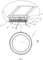
- the numeral 1 indicates a radial pneumatic tyre comprising an inner radial carcass 2 and an outer tread 3 separated from one another by a tread belt 4 defined by a pack of tread plies 5 overlapping one another.
- the tread 3 comprises a tread band 6 and a cushion 6a overlapping one another.
- the tread band 6 comprises an inner layer 7 and an outer layer 8.
- the inner layer 7 is made with a compound B with relatively low hysteresis loss, whilst the outer layer 8 is made with a compound A with relatively high hysteresis loss.
- connection surface 9 has a corrugated conformation that is such to provide an alternation of interpenetrating longitudinal portions 10 between the two layers 7 and 8.
- the interpenetrating portions 10 extend parallel to an axis of rotation X of the pneumatic tyre.
- the interpenetrating portions 10 are parallel to one another, all having the same height h.
- the tread band 6 comprises an outer portion of height S made only from compound A, a central portion of height h made from the alternation of interpenetrating portions 10, and an inner portion of height Y made only from compound B.
- a first specimen (I) was made entirely with compound A
- a second specimen (II) was made entirely with compound B
- a third specimen (III) was made with a 6 mm layer of compound B and a 2 mm layer of compound A
- a fourth specimen (IV) was made with a 7 mm layer of compound B and a 1 mm layer of compound A.
- the fifth specimen (V) which represents the solution of the invention, comprises two layers made respectively with compounds A and B, which implement a relative plurality of interpenetration portions within the interface.
- the connection surface between the layers has a corrugated conformation that is such to implement the longitudinal interpenetration portions.
- the interpenetration portions have a height equal to 2 mm.
- the fifth specimen will consist of a 5 mm portion filled with compound B, a 1 mm portion filled with compound A and an intermediate 2 mm portion, wherein the compounds A and B interpenetrate in an alternating manner.
- the two layers made with compounds A and B respectively have a planar connection surface
- the two layers made with compounds A and B respectively have a corrugated connection surface that is such to provide a plurality of alternated interpenetrating longitudinal portions, so that the total volume of the two components is the same in relation to that of specimen III.
- Table I shows the compositions of the compounds A and B used in the specimens.
- E-SBR is a polymeric base obtained by means of an emulsion polymerization process with an average molecular weight of between 800-1500 ⁇ 10 3 and 500-900 ⁇ 10 3 , respectively, with a styrene content of between 20 and 45% and used with an oil content of between 0 and 30%;
- S-SBR is a polymeric base obtained by means of a solution polymerization process with an average molecular weight of between 800-1500 ⁇ 10 3 and 500-900 ⁇ 10 3 , respectively, with a styrene content of between 20 and 45%.
- the silica used is marketed under the name ULTRASIL VN3 by the DEGUSSA company.
- the carbon black used is marketed under the name Vulcan 7H (N234) by the CABOT company.
- the silane used is marketed under the name SI 69 by the DEGUSSA company.
- TBBS is the acronym for the compound N-tert-butyl-2-benzotiazilsulfenammide
- MBTS is the acronym for the compound mercapto benzothiazole disulfide
- DPG is the acronym for the compound diphenyl guanidine
- 6PPD is the acronym for N-1,3-dimethylbutyl-N'-phenyl-para-phenylenediamine.
- the compounds A and B described above have a dynamic modulus at 30 °C of 10 and 8 MPa, respectively, and a tan ⁇ at 60 °C of 0.200 and 0.170, respectively.
- the braking performance was evaluated by comparing the coefficient of friction of the compounds, obtained with a linear friction meter at a speed of 500 mm/s, at a temperature of 5 °C under wet conditions. The results were obtained by comparing the respective coefficients of friction: the higher the index, the higher the coefficient of friction and, therefore, the wet grip.
- Table II shows the values of braking and rolling resistance indexed to the values of the first specimen (I). TABLE II Specimens I II III IX V Braking 100 90 95 90 120 Rolling resistance 100 110 105 108 105
- the present invention starting from a known tread conformation comprising an inner layer made with a compound with relatively low hysteresis loss and an outer layer made with a compound with relatively high hysteresis loss, can, by virtue of the presence of the interpenetrating portions of the two layers, greatly boost performance in terms of braking, maintaining, at the same time, the advantages obtained in terms of rolling resistance.
Landscapes
- Engineering & Computer Science (AREA)
- Mechanical Engineering (AREA)
- Tires In General (AREA)
- Transition And Organic Metals Composition Catalysts For Addition Polymerization (AREA)
- Vehicle Body Suspensions (AREA)
Description
- The present invention relates to a pneumatic tyre for road vehicles.
- In particular, the present invention relates to a radial pneumatic tyre for road vehicles, comprising a tread consisting of an outer portion made with a compound with relatively high hysteresis loss, and an inner portion made with a compound with relatively low hysteresis loss and having a connection interface with the outer portion having a special geometry.
- In the field of pneumatic tyres for road vehicles, it is known that a low rolling resistance and a good wear resistance on the one hand and good road holding and braking ability in the dry or wet on the other hand are characteristics that are difficult to obtain with the same pneumatic tyre. In fact, whilst in order to confer good rolling resistance and good wear resistance to a pneumatic tyre, treads made with compounds with low hysteresis loss are used, in order to confer good road holding and braking ability to a pneumatic tyre, treads with compounds with relatively higher hysteresis loss become necessary.
- Consequently, an optimal tread compound for simultaneously enhancing all of the dynamic responses of the tread of a pneumatic tyre should exhibit opposing hysteresis characteristics, at least over certain required performance limits.
- In
EP-0 864 446 andEP-0 864 447 pneumatic tyres of the previously defined type are described that are provided with treads made using two compounds, one with a low hysteresis loss and the other with a high hysteresis loss, in order to form two or more axially adjacent annular tread strips. In each pair of axially contiguous strips, one is made using one of the two compounds and the other is made using the other of the two compounds. - Other relevant prior art is known from
EP 2 990 223 A1 ,JP 3 273981 B2 JP 2002 205513 A JP S61 229602 A JP 2001 088513 A - The known multi-compound treads obtained by axially distributing the various strips as a function of the dynamic characteristics to be enhanced, through capable of ensuring the required performance during the first use thereof, are however subject to non-uniform wear with the result that, after a short period of time, the compromise that was so difficult to achieve, is lost.
- A further solution that has been adopted concerns the implementation of a tread composed of an outer layer made with a compound with relatively high hysteresis loss, and an inner layer made with a compound with relatively low hysteresis loss. The two layers are radially adjacent to one another and have a substantially planar connection interface surface, i.e., such to avoid any interpenetration of one layer within the other.
- Notwithstanding such a solution having provided obvious improvements in terms of rolling resistance, without leading to any deterioration in braking performance, the need was however felt to provide pneumatic tyres that also result in obvious improvements in terms of braking. In fact, such a solution makes it possible to improve the balance of the required performance but nonetheless to a limited extent, since the overall performance is a compromise resulting from the contribution of the two components.
- The inventors of the present invention have found that by implementing a particular connection surface between the two layers with different hysteresis losses, it is possible to obtain surprising advantages in terms of braking, while maintaining unaltered the advantages obtained in terms of rolling resistance.
- The object of the present invention is a pneumatic tyre for road vehicles comprising a tread portion comprising an outer layer made with a compound A having a dynamic modulus at 30 °C of between 5 and 10 MPa and a tanδ at 60 °C of between 0.400 and 0.100, and an inner layer made with a compound B having a dynamic modulus at 30 °C that is lower than that of said compound A of a value of between 0.5 to 10 MPa and a tanδ at 60 °C that is lower than that of said compound A of value of between 0.01 and 0.20; said outer layer and said inner layer being in contact with each other by means of a connection surface; said pneumatic tyre being characterized in that said connection surface has a corrugated conformation that is such to provide an alternated plurality of interpenetrating longitudinal portions; each of said interpenetrating portions extending parallel to an axis of rotation X of the pneumatic tyre.
- The dynamic properties were measured in accordance with the ISO 4664 standard. As is known to a technician in the field, the values of tanδ at 60 °C are strictly correlated to the rolling resistance: the lower the tanδ value at 60 °C, the better the rolling resistance.
- Here and hereinafter interpenetrating portion refers to a portion of one of the two (inner or outer) layers of the tread that is found to be axially flanked by two portions of the other (outer or inner) layer of the tread. Preferably, said connection surface implements a regular continuity of interpenetrating portions, all of equal size and parallel to one another. In this way, said tread portion comprises an outer portion made only from compound A, a central portion made from the alternation of interpenetrating portions, and an inner portion made only from compound B.
- Preferably, the ratio between the thickness of said outer portion and the thickness of said inner portion is between 0.1 and 0.9.
- Preferably, the ratio between said central portion and the overall thickness of the tread portion is between 0.2 and 0.8.
- The invention will now be described with reference to the accompanying figure, which illustrates, by means of a cross-section enlargement, a portion of a preferred embodiment of the pneumatic tyre according to the present invention.
- With reference to
figure 1 , the numeral 1 indicates a radial pneumatic tyre comprising an inner radial carcass 2 and an outer tread 3 separated from one another by a tread belt 4 defined by a pack oftread plies 5 overlapping one another. - In the example illustrated, the tread 3 comprises a
tread band 6 and a cushion 6a overlapping one another. Thetread band 6 comprises aninner layer 7 and an outer layer 8. - The
inner layer 7 is made with a compound B with relatively low hysteresis loss, whilst the outer layer 8 is made with a compound A with relatively high hysteresis loss. - The
inner layer 7 and the outer layer 8 are in contact to one another by means of a connection surface 9. The connection surface 9 has a corrugated conformation that is such to provide an alternation of interpenetrating longitudinal portions 10 between the twolayers 7 and 8. The interpenetrating portions 10 extend parallel to an axis of rotation X of the pneumatic tyre. - According to the preferred embodiment shown in the figure, the interpenetrating portions 10 are parallel to one another, all having the same height h.
- In this way, the
tread band 6 comprises an outer portion of height S made only from compound A, a central portion of height h made from the alternation of interpenetrating portions 10, and an inner portion of height Y made only from compound B. - In order to verify the advantages deriving from the solution of the present invention, five specimens were made, all having the same thickness equal to 8 mm. The five specimens, made as described below, were subjected to evaluations in terms of braking and rolling resistance.
- A first specimen (I) was made entirely with compound A, a second specimen (II) was made entirely with compound B, a third specimen (III) was made with a 6 mm layer of compound B and a 2 mm layer of compound A and a fourth specimen (IV) was made with a 7 mm layer of compound B and a 1 mm layer of compound A. The fifth specimen (V), which represents the solution of the invention, comprises two layers made respectively with compounds A and B, which implement a relative plurality of interpenetration portions within the interface. In particular, the connection surface between the layers has a corrugated conformation that is such to implement the longitudinal interpenetration portions. The interpenetration portions have a height equal to 2 mm. In this way the fifth specimen will consist of a 5 mm portion filled with compound B, a 1 mm portion filled with compound A and an intermediate 2 mm portion, wherein the compounds A and B interpenetrate in an alternating manner.
- In essence, whilst with the third (III) and fourth (IV) specimens the two layers made with compounds A and B respectively have a planar connection surface, in the fifth specimen (V) the two layers made with compounds A and B respectively have a corrugated connection surface that is such to provide a plurality of alternated interpenetrating longitudinal portions, so that the total volume of the two components is the same in relation to that of specimen III.
- Table I shows the compositions of the compounds A and B used in the specimens.
TABLE I COMPOUND A COMPOUND B POLYMERIC BASE WITH OIL E-SBR 72.9 72.9 S-SBR 56.4 56.4 FILLER SILICA 70.0 40.0 CARBON BLACK 10.0 20.0 BINDER AGENT SILANE 7.0 4.0 MICROCRYSTALLINE WAX 1.0 1.0 STEARIC ACID 1.0 1.0 AROMATIC OIL 9.0 4.0 ZINC OXIDE 2.0 2.0 SULFUR 2.0 2.0 VULCANIZING AGENTS ACCELERATOR TBBS 1.0 1.2 ACCELERATOR MBTS 0.5 0.3 ACCELERATOR DPG 1.5 1.1 ANTIOXIDANT 6PPD 1.5 1.5 DRY POLYMERIC BASE 100 100 - E-SBR is a polymeric base obtained by means of an emulsion polymerization process with an average molecular weight of between 800-1500×103 and 500-900×103, respectively, with a styrene content of between 20 and 45% and used with an oil content of between 0 and 30%;
S-SBR is a polymeric base obtained by means of a solution polymerization process with an average molecular weight of between 800-1500×103 and 500-900×103, respectively, with a styrene content of between 20 and 45%. - The silica used is marketed under the name ULTRASIL VN3 by the DEGUSSA company.
- The carbon black used is marketed under the name Vulcan 7H (N234) by the CABOT company.
- The silane used is marketed under the name SI 69 by the DEGUSSA company.
- TBBS is the acronym for the compound N-tert-butyl-2-benzotiazilsulfenammide; MBTS is the acronym for the compound mercapto benzothiazole disulfide; DPG is the acronym for the compound diphenyl guanidine; 6PPD is the acronym for N-1,3-dimethylbutyl-N'-phenyl-para-phenylenediamine.
- The compounds A and B described above have a dynamic modulus at 30 °C of 10 and 8 MPa, respectively, and a tanδ at 60 °C of 0.200 and 0.170, respectively.
- The five specimens above were subjected to testing according to the ISO 4664 standard in order to evaluate the dynamic properties.
- The braking performance was evaluated by comparing the coefficient of friction of the compounds, obtained with a linear friction meter at a speed of 500 mm/s, at a temperature of 5 °C under wet conditions. The results were obtained by comparing the respective coefficients of friction: the higher the index, the higher the coefficient of friction and, therefore, the wet grip.
- In particular, the performance in terms of rolling resistance was correlated to the values of tanδ at 60 °C.
- Table II shows the values of braking and rolling resistance indexed to the values of the first specimen (I).
TABLE II Specimens I II III IX V Braking 100 90 95 90 120 Rolling resistance 100 110 105 108 105 - As is evident from the data of Table III, the conformation of the contact surface of the two layers in specimen V confers a clear improvement in terms of braking compared to specimens III and IV. Specimens III and IV, despite comprising the combination of the two layers with different hysteresis losses, nonetheless fail to achieve the advantages in terms of braking achieved by the solution of the present invention (specimen V).
- In other words, the present invention, starting from a known tread conformation comprising an inner layer made with a compound with relatively low hysteresis loss and an outer layer made with a compound with relatively high hysteresis loss, can, by virtue of the presence of the interpenetrating portions of the two layers, greatly boost performance in terms of braking, maintaining, at the same time, the advantages obtained in terms of rolling resistance.
Claims (4)
- Pneumatic tyre (1) for road vehicles comprising a tread portion (6) comprising an outer layer (8) made with a compound A having a dynamic modulus at 30 °C of between 5 and 15 MPa and a tanδ at 60 °C of between 0.400 and 0.100, and an inner layer made with a compound B having a dynamic modulus at 30 °C that is lower than that of said compound A of a value of between 0.5 and 10 MPa and a tanδ at 60 °C that is lower than that of said compound A of value of between 0.01 and 0.20, wherein the dynamic modulus and the tanδ of compounds A and B are measured in accordance with the ISO 4664 standard; said outer layer (8) and said inner layer (7) being in contact with each other by means of a connection surface (9); said pneumatic tyre being characterized in that said connection surface (9) has a corrugated conformation that is such to provide an alternated plurality of interpenetrating longitudinal portions (10); each of said interpenetrating portions (10) extending parallel to an axis of rotation X of the pneumatic tyre.
- Pneumatic tyre for road vehicles according to claim 1, characterized in that said connection surface (9) implements a regular continuity of interpenetrating portions (10) all of equal size and parallel to one another; said tread portion (6) comprising an outer portion made only from compound A, a central portion made from the alternation of interpenetrating portions (10), and an inner portion made only from compound B.
- Pneumatic tyre for road vehicles according to claim 2, characterized in that the ratio between the thickness of said outer portion and the thickness of said inner portion is between 0.1 and 0.9.
- Pneumatic tyre for road vehicles according to claim 2, characterized in that the ratio between said central portion and the overall thickness of the tread portion is between 0.2 and 0.8.
Applications Claiming Priority (2)
| Application Number | Priority Date | Filing Date | Title |
|---|---|---|---|
| IT102018000004507A IT201800004507A1 (en) | 2018-04-13 | 2018-04-13 | TIRE FOR ROAD VEHICLES |
| PCT/IB2019/053036 WO2019198048A1 (en) | 2018-04-13 | 2019-04-12 | Pneumatic tyre for road vehicles |
Publications (2)
| Publication Number | Publication Date |
|---|---|
| EP3774395A1 EP3774395A1 (en) | 2021-02-17 |
| EP3774395B1 true EP3774395B1 (en) | 2022-02-23 |
Family
ID=62875163
Family Applications (1)
| Application Number | Title | Priority Date | Filing Date |
|---|---|---|---|
| EP19724927.9A Not-in-force EP3774395B1 (en) | 2018-04-13 | 2019-04-12 | Pneumatic tyre for road vehicles |
Country Status (5)
| Country | Link |
|---|---|
| US (1) | US20210155047A1 (en) |
| EP (1) | EP3774395B1 (en) |
| JP (1) | JP6951589B2 (en) |
| IT (1) | IT201800004507A1 (en) |
| WO (1) | WO2019198048A1 (en) |
Families Citing this family (1)
| Publication number | Priority date | Publication date | Assignee | Title |
|---|---|---|---|---|
| IT201900019946A1 (en) * | 2019-10-29 | 2021-04-29 | Bridgestone Europe Nv Sa | PROCEDURE FOR MAKING A MULTI-COMPOUND TREAD FOR ROAD VEHICLE TIRES |
Family Cites Families (10)
| Publication number | Priority date | Publication date | Assignee | Title |
|---|---|---|---|---|
| JPS5963206A (en) * | 1982-10-04 | 1984-04-10 | Bridgestone Corp | Pneumatic tire for heavy load |
| JPS61229602A (en) * | 1985-04-04 | 1986-10-13 | Ohtsu Tire & Rubber Co Ltd | Automobile tire tread |
| JP3273981B2 (en) * | 1992-11-20 | 2002-04-15 | 東洋ゴム工業株式会社 | Pneumatic radial tires for trucks and buses |
| US6336486B1 (en) * | 1997-04-04 | 2002-01-08 | Bridgestone Corporation | Pneumatic radical tire having cap base tread |
| JP2001088513A (en) * | 1999-09-27 | 2001-04-03 | Bridgestone Corp | Pneumatic tire |
| JP2002205513A (en) * | 2001-01-12 | 2002-07-23 | Bridgestone Corp | Pneumatic radial tire |
| JP2009001081A (en) * | 2007-06-19 | 2009-01-08 | Bridgestone Corp | Pneumatic tire for motorcycle |
| WO2012005247A1 (en) * | 2010-07-05 | 2012-01-12 | 株式会社ブリヂストン | Pneumatic tire for two-wheeled vehicle |
| JP5551041B2 (en) * | 2010-09-30 | 2014-07-16 | 株式会社ブリヂストン | Pneumatic tire |
| JP6014541B2 (en) * | 2013-04-24 | 2016-10-25 | 株式会社ブリヂストン | Pneumatic tire |
-
2018
- 2018-04-13 IT IT102018000004507A patent/IT201800004507A1/en unknown
-
2019
- 2019-04-12 WO PCT/IB2019/053036 patent/WO2019198048A1/en not_active Ceased
- 2019-04-12 US US17/046,982 patent/US20210155047A1/en not_active Abandoned
- 2019-04-12 EP EP19724927.9A patent/EP3774395B1/en not_active Not-in-force
- 2019-04-12 JP JP2020552783A patent/JP6951589B2/en active Active
Also Published As
| Publication number | Publication date |
|---|---|
| EP3774395A1 (en) | 2021-02-17 |
| JP2021517873A (en) | 2021-07-29 |
| US20210155047A1 (en) | 2021-05-27 |
| IT201800004507A1 (en) | 2019-10-13 |
| WO2019198048A1 (en) | 2019-10-17 |
| JP6951589B2 (en) | 2021-10-20 |
Similar Documents
| Publication | Publication Date | Title |
|---|---|---|
| EP1580037B1 (en) | Pneumatic radial tire | |
| EP2940071B1 (en) | Rubber composition for pneumatic tires for construction vehicles | |
| AU714346B2 (en) | Tire having silica reinforced rubber tread with carbon black reinforced rubber envelope | |
| EP1636050B1 (en) | Tyre for vehicle wheels with tread band of cap and base construction | |
| CN107531097B (en) | Tyre with tread comprising reinforcing elements | |
| US8104523B2 (en) | Pneumatic tire and process for its manufacture | |
| EP3141402A1 (en) | Tire | |
| EP2657049B1 (en) | Pneumatic tire | |
| US20140326377A1 (en) | Tyre having a tread comprising a felt | |
| CN111655512A (en) | A tire with a tread base comprising multiple materials | |
| WO2018118479A1 (en) | Heavy truck tire | |
| CA1228282A (en) | Pneumatic radial tire having a good high-speed running performance | |
| EP2421716B1 (en) | Heavy load pneumatic tire | |
| JP2023070179A (en) | tire | |
| JP6054910B2 (en) | Pneumatic tire | |
| US20210155047A1 (en) | Pneumatic tire for road vehicles | |
| EP3820937B1 (en) | Truck and bus radial pneumatic tyre of a driving wheel | |
| JP4260240B2 (en) | Pneumatic radial tire | |
| US12358324B2 (en) | Pneumatic tire | |
| EP3845398B1 (en) | Pneumatic tire | |
| JP2019194282A (en) | Tire rubber composition and pneumatic tire | |
| RU2321500C1 (en) | Tire for vehicles | |
| DE102017122284A1 (en) | TIRE | |
| JPH07117412A (en) | Pneumatic tire for heavy load | |
| DE102017116978A1 (en) | tire |
Legal Events
| Date | Code | Title | Description |
|---|---|---|---|
| STAA | Information on the status of an ep patent application or granted ep patent |
Free format text: STATUS: UNKNOWN |
|
| STAA | Information on the status of an ep patent application or granted ep patent |
Free format text: STATUS: THE INTERNATIONAL PUBLICATION HAS BEEN MADE |
|
| PUAI | Public reference made under article 153(3) epc to a published international application that has entered the european phase |
Free format text: ORIGINAL CODE: 0009012 |
|
| STAA | Information on the status of an ep patent application or granted ep patent |
Free format text: STATUS: REQUEST FOR EXAMINATION WAS MADE |
|
| 17P | Request for examination filed |
Effective date: 20201109 |
|
| AK | Designated contracting states |
Kind code of ref document: A1 Designated state(s): AL AT BE BG CH CY CZ DE DK EE ES FI FR GB GR HR HU IE IS IT LI LT LU LV MC MK MT NL NO PL PT RO RS SE SI SK SM TR |
|
| AX | Request for extension of the european patent |
Extension state: BA ME |
|
| DAV | Request for validation of the european patent (deleted) | ||
| DAX | Request for extension of the european patent (deleted) | ||
| GRAP | Despatch of communication of intention to grant a patent |
Free format text: ORIGINAL CODE: EPIDOSNIGR1 |
|
| STAA | Information on the status of an ep patent application or granted ep patent |
Free format text: STATUS: GRANT OF PATENT IS INTENDED |
|
| INTG | Intention to grant announced |
Effective date: 20210916 |
|
| GRAS | Grant fee paid |
Free format text: ORIGINAL CODE: EPIDOSNIGR3 |
|
| GRAA | (expected) grant |
Free format text: ORIGINAL CODE: 0009210 |
|
| STAA | Information on the status of an ep patent application or granted ep patent |
Free format text: STATUS: THE PATENT HAS BEEN GRANTED |
|
| AK | Designated contracting states |
Kind code of ref document: B1 Designated state(s): AL AT BE BG CH CY CZ DE DK EE ES FI FR GB GR HR HU IE IS IT LI LT LU LV MC MK MT NL NO PL PT RO RS SE SI SK SM TR |
|
| REG | Reference to a national code |
Ref country code: GB Ref legal event code: FG4D |
|
| REG | Reference to a national code |
Ref country code: CH Ref legal event code: EP |
|
| REG | Reference to a national code |
Ref country code: DE Ref legal event code: R096 Ref document number: 602019011910 Country of ref document: DE |
|
| REG | Reference to a national code |
Ref country code: AT Ref legal event code: REF Ref document number: 1470173 Country of ref document: AT Kind code of ref document: T Effective date: 20220315 |
|
| REG | Reference to a national code |
Ref country code: IE Ref legal event code: FG4D |
|
| REG | Reference to a national code |
Ref country code: LT Ref legal event code: MG9D |
|
| REG | Reference to a national code |
Ref country code: NL Ref legal event code: MP Effective date: 20220223 |
|
| REG | Reference to a national code |
Ref country code: AT Ref legal event code: MK05 Ref document number: 1470173 Country of ref document: AT Kind code of ref document: T Effective date: 20220223 |
|
| PG25 | Lapsed in a contracting state [announced via postgrant information from national office to epo] |
Ref country code: SE Free format text: LAPSE BECAUSE OF FAILURE TO SUBMIT A TRANSLATION OF THE DESCRIPTION OR TO PAY THE FEE WITHIN THE PRESCRIBED TIME-LIMIT Effective date: 20220223 Ref country code: RS Free format text: LAPSE BECAUSE OF FAILURE TO SUBMIT A TRANSLATION OF THE DESCRIPTION OR TO PAY THE FEE WITHIN THE PRESCRIBED TIME-LIMIT Effective date: 20220223 Ref country code: PT Free format text: LAPSE BECAUSE OF FAILURE TO SUBMIT A TRANSLATION OF THE DESCRIPTION OR TO PAY THE FEE WITHIN THE PRESCRIBED TIME-LIMIT Effective date: 20220623 Ref country code: NO Free format text: LAPSE BECAUSE OF FAILURE TO SUBMIT A TRANSLATION OF THE DESCRIPTION OR TO PAY THE FEE WITHIN THE PRESCRIBED TIME-LIMIT Effective date: 20220523 Ref country code: NL Free format text: LAPSE BECAUSE OF FAILURE TO SUBMIT A TRANSLATION OF THE DESCRIPTION OR TO PAY THE FEE WITHIN THE PRESCRIBED TIME-LIMIT Effective date: 20220223 Ref country code: LT Free format text: LAPSE BECAUSE OF FAILURE TO SUBMIT A TRANSLATION OF THE DESCRIPTION OR TO PAY THE FEE WITHIN THE PRESCRIBED TIME-LIMIT Effective date: 20220223 Ref country code: HR Free format text: LAPSE BECAUSE OF FAILURE TO SUBMIT A TRANSLATION OF THE DESCRIPTION OR TO PAY THE FEE WITHIN THE PRESCRIBED TIME-LIMIT Effective date: 20220223 Ref country code: ES Free format text: LAPSE BECAUSE OF FAILURE TO SUBMIT A TRANSLATION OF THE DESCRIPTION OR TO PAY THE FEE WITHIN THE PRESCRIBED TIME-LIMIT Effective date: 20220223 Ref country code: BG Free format text: LAPSE BECAUSE OF FAILURE TO SUBMIT A TRANSLATION OF THE DESCRIPTION OR TO PAY THE FEE WITHIN THE PRESCRIBED TIME-LIMIT Effective date: 20220523 |
|
| PG25 | Lapsed in a contracting state [announced via postgrant information from national office to epo] |
Ref country code: PL Free format text: LAPSE BECAUSE OF FAILURE TO SUBMIT A TRANSLATION OF THE DESCRIPTION OR TO PAY THE FEE WITHIN THE PRESCRIBED TIME-LIMIT Effective date: 20220223 Ref country code: LV Free format text: LAPSE BECAUSE OF FAILURE TO SUBMIT A TRANSLATION OF THE DESCRIPTION OR TO PAY THE FEE WITHIN THE PRESCRIBED TIME-LIMIT Effective date: 20220223 Ref country code: GR Free format text: LAPSE BECAUSE OF FAILURE TO SUBMIT A TRANSLATION OF THE DESCRIPTION OR TO PAY THE FEE WITHIN THE PRESCRIBED TIME-LIMIT Effective date: 20220524 Ref country code: FI Free format text: LAPSE BECAUSE OF FAILURE TO SUBMIT A TRANSLATION OF THE DESCRIPTION OR TO PAY THE FEE WITHIN THE PRESCRIBED TIME-LIMIT Effective date: 20220223 Ref country code: AT Free format text: LAPSE BECAUSE OF FAILURE TO SUBMIT A TRANSLATION OF THE DESCRIPTION OR TO PAY THE FEE WITHIN THE PRESCRIBED TIME-LIMIT Effective date: 20220223 |
|
| PG25 | Lapsed in a contracting state [announced via postgrant information from national office to epo] |
Ref country code: IS Free format text: LAPSE BECAUSE OF FAILURE TO SUBMIT A TRANSLATION OF THE DESCRIPTION OR TO PAY THE FEE WITHIN THE PRESCRIBED TIME-LIMIT Effective date: 20220623 |
|
| PG25 | Lapsed in a contracting state [announced via postgrant information from national office to epo] |
Ref country code: SM Free format text: LAPSE BECAUSE OF FAILURE TO SUBMIT A TRANSLATION OF THE DESCRIPTION OR TO PAY THE FEE WITHIN THE PRESCRIBED TIME-LIMIT Effective date: 20220223 Ref country code: SK Free format text: LAPSE BECAUSE OF FAILURE TO SUBMIT A TRANSLATION OF THE DESCRIPTION OR TO PAY THE FEE WITHIN THE PRESCRIBED TIME-LIMIT Effective date: 20220223 Ref country code: RO Free format text: LAPSE BECAUSE OF FAILURE TO SUBMIT A TRANSLATION OF THE DESCRIPTION OR TO PAY THE FEE WITHIN THE PRESCRIBED TIME-LIMIT Effective date: 20220223 Ref country code: EE Free format text: LAPSE BECAUSE OF FAILURE TO SUBMIT A TRANSLATION OF THE DESCRIPTION OR TO PAY THE FEE WITHIN THE PRESCRIBED TIME-LIMIT Effective date: 20220223 Ref country code: DK Free format text: LAPSE BECAUSE OF FAILURE TO SUBMIT A TRANSLATION OF THE DESCRIPTION OR TO PAY THE FEE WITHIN THE PRESCRIBED TIME-LIMIT Effective date: 20220223 Ref country code: CZ Free format text: LAPSE BECAUSE OF FAILURE TO SUBMIT A TRANSLATION OF THE DESCRIPTION OR TO PAY THE FEE WITHIN THE PRESCRIBED TIME-LIMIT Effective date: 20220223 |
|
| REG | Reference to a national code |
Ref country code: DE Ref legal event code: R097 Ref document number: 602019011910 Country of ref document: DE |
|
| PG25 | Lapsed in a contracting state [announced via postgrant information from national office to epo] |
Ref country code: AL Free format text: LAPSE BECAUSE OF FAILURE TO SUBMIT A TRANSLATION OF THE DESCRIPTION OR TO PAY THE FEE WITHIN THE PRESCRIBED TIME-LIMIT Effective date: 20220223 |
|
| REG | Reference to a national code |
Ref country code: CH Ref legal event code: PL |
|
| PLBE | No opposition filed within time limit |
Free format text: ORIGINAL CODE: 0009261 |
|
| STAA | Information on the status of an ep patent application or granted ep patent |
Free format text: STATUS: NO OPPOSITION FILED WITHIN TIME LIMIT |
|
| REG | Reference to a national code |
Ref country code: BE Ref legal event code: MM Effective date: 20220430 |
|
| PG25 | Lapsed in a contracting state [announced via postgrant information from national office to epo] |
Ref country code: MC Free format text: LAPSE BECAUSE OF FAILURE TO SUBMIT A TRANSLATION OF THE DESCRIPTION OR TO PAY THE FEE WITHIN THE PRESCRIBED TIME-LIMIT Effective date: 20220223 Ref country code: LU Free format text: LAPSE BECAUSE OF NON-PAYMENT OF DUE FEES Effective date: 20220412 Ref country code: LI Free format text: LAPSE BECAUSE OF NON-PAYMENT OF DUE FEES Effective date: 20220430 Ref country code: CH Free format text: LAPSE BECAUSE OF NON-PAYMENT OF DUE FEES Effective date: 20220430 |
|
| 26N | No opposition filed |
Effective date: 20221124 |
|
| PG25 | Lapsed in a contracting state [announced via postgrant information from national office to epo] |
Ref country code: SI Free format text: LAPSE BECAUSE OF FAILURE TO SUBMIT A TRANSLATION OF THE DESCRIPTION OR TO PAY THE FEE WITHIN THE PRESCRIBED TIME-LIMIT Effective date: 20220223 Ref country code: BE Free format text: LAPSE BECAUSE OF NON-PAYMENT OF DUE FEES Effective date: 20220430 |
|
| PG25 | Lapsed in a contracting state [announced via postgrant information from national office to epo] |
Ref country code: IE Free format text: LAPSE BECAUSE OF NON-PAYMENT OF DUE FEES Effective date: 20220412 |
|
| P01 | Opt-out of the competence of the unified patent court (upc) registered |
Effective date: 20230511 |
|
| PG25 | Lapsed in a contracting state [announced via postgrant information from national office to epo] |
Ref country code: IT Free format text: LAPSE BECAUSE OF FAILURE TO SUBMIT A TRANSLATION OF THE DESCRIPTION OR TO PAY THE FEE WITHIN THE PRESCRIBED TIME-LIMIT Effective date: 20220223 |
|
| GBPC | Gb: european patent ceased through non-payment of renewal fee |
Effective date: 20230412 |
|
| PG25 | Lapsed in a contracting state [announced via postgrant information from national office to epo] |
Ref country code: GB Free format text: LAPSE BECAUSE OF NON-PAYMENT OF DUE FEES Effective date: 20230412 |
|
| PG25 | Lapsed in a contracting state [announced via postgrant information from national office to epo] |
Ref country code: GB Free format text: LAPSE BECAUSE OF NON-PAYMENT OF DUE FEES Effective date: 20230412 |
|
| PG25 | Lapsed in a contracting state [announced via postgrant information from national office to epo] |
Ref country code: MK Free format text: LAPSE BECAUSE OF FAILURE TO SUBMIT A TRANSLATION OF THE DESCRIPTION OR TO PAY THE FEE WITHIN THE PRESCRIBED TIME-LIMIT Effective date: 20220223 Ref country code: CY Free format text: LAPSE BECAUSE OF FAILURE TO SUBMIT A TRANSLATION OF THE DESCRIPTION OR TO PAY THE FEE WITHIN THE PRESCRIBED TIME-LIMIT Effective date: 20220223 |
|
| PG25 | Lapsed in a contracting state [announced via postgrant information from national office to epo] |
Ref country code: HU Free format text: LAPSE BECAUSE OF FAILURE TO SUBMIT A TRANSLATION OF THE DESCRIPTION OR TO PAY THE FEE WITHIN THE PRESCRIBED TIME-LIMIT; INVALID AB INITIO Effective date: 20190412 |
|
| PGFP | Annual fee paid to national office [announced via postgrant information from national office to epo] |
Ref country code: FR Payment date: 20240320 Year of fee payment: 6 |
|
| PGFP | Annual fee paid to national office [announced via postgrant information from national office to epo] |
Ref country code: DE Payment date: 20240320 Year of fee payment: 6 |
|
| PG25 | Lapsed in a contracting state [announced via postgrant information from national office to epo] |
Ref country code: MT Free format text: LAPSE BECAUSE OF FAILURE TO SUBMIT A TRANSLATION OF THE DESCRIPTION OR TO PAY THE FEE WITHIN THE PRESCRIBED TIME-LIMIT Effective date: 20220223 |
|
| REG | Reference to a national code |
Ref country code: DE Ref legal event code: R119 Ref document number: 602019011910 Country of ref document: DE |
|
| PG25 | Lapsed in a contracting state [announced via postgrant information from national office to epo] |
Ref country code: TR Free format text: LAPSE BECAUSE OF FAILURE TO SUBMIT A TRANSLATION OF THE DESCRIPTION OR TO PAY THE FEE WITHIN THE PRESCRIBED TIME-LIMIT Effective date: 20220223 |
|
| PG25 | Lapsed in a contracting state [announced via postgrant information from national office to epo] |
Ref country code: DE Free format text: LAPSE BECAUSE OF NON-PAYMENT OF DUE FEES Effective date: 20251104 |
|
| PG25 | Lapsed in a contracting state [announced via postgrant information from national office to epo] |
Ref country code: FR Free format text: LAPSE BECAUSE OF NON-PAYMENT OF DUE FEES Effective date: 20250430 |