EP3774063B1 - Separation of fluids - Google Patents
Separation of fluids Download PDFInfo
- Publication number
- EP3774063B1 EP3774063B1 EP19784689.2A EP19784689A EP3774063B1 EP 3774063 B1 EP3774063 B1 EP 3774063B1 EP 19784689 A EP19784689 A EP 19784689A EP 3774063 B1 EP3774063 B1 EP 3774063B1
- Authority
- EP
- European Patent Office
- Prior art keywords
- centrifuge
- motor
- capsule
- axis
- inner ring
- Prior art date
- Legal status (The legal status is an assumption and is not a legal conclusion. Google has not performed a legal analysis and makes no representation as to the accuracy of the status listed.)
- Active
Links
Images

Classifications
-
- B—PERFORMING OPERATIONS; TRANSPORTING
- B04—CENTRIFUGAL APPARATUS OR MACHINES FOR CARRYING-OUT PHYSICAL OR CHEMICAL PROCESSES
- B04B—CENTRIFUGES
- B04B9/00—Drives specially designed for centrifuges; Arrangement or disposition of transmission gearing; Suspending or balancing rotary bowls
-
- B—PERFORMING OPERATIONS; TRANSPORTING
- B04—CENTRIFUGAL APPARATUS OR MACHINES FOR CARRYING-OUT PHYSICAL OR CHEMICAL PROCESSES
- B04B—CENTRIFUGES
- B04B9/00—Drives specially designed for centrifuges; Arrangement or disposition of transmission gearing; Suspending or balancing rotary bowls
- B04B9/02—Electric motor drives
-
- B—PERFORMING OPERATIONS; TRANSPORTING
- B04—CENTRIFUGAL APPARATUS OR MACHINES FOR CARRYING-OUT PHYSICAL OR CHEMICAL PROCESSES
- B04B—CENTRIFUGES
- B04B1/00—Centrifuges with rotary bowls provided with solid jackets for separating predominantly liquid mixtures with or without solid particles
-
- B—PERFORMING OPERATIONS; TRANSPORTING
- B04—CENTRIFUGAL APPARATUS OR MACHINES FOR CARRYING-OUT PHYSICAL OR CHEMICAL PROCESSES
- B04B—CENTRIFUGES
- B04B5/00—Other centrifuges
-
- B—PERFORMING OPERATIONS; TRANSPORTING
- B04—CENTRIFUGAL APPARATUS OR MACHINES FOR CARRYING-OUT PHYSICAL OR CHEMICAL PROCESSES
- B04B—CENTRIFUGES
- B04B7/00—Elements of centrifuges
- B04B7/08—Rotary bowls
-
- B—PERFORMING OPERATIONS; TRANSPORTING
- B04—CENTRIFUGAL APPARATUS OR MACHINES FOR CARRYING-OUT PHYSICAL OR CHEMICAL PROCESSES
- B04B—CENTRIFUGES
- B04B9/00—Drives specially designed for centrifuges; Arrangement or disposition of transmission gearing; Suspending or balancing rotary bowls
- B04B9/02—Electric motor drives
- B04B9/04—Direct drive
-
- B—PERFORMING OPERATIONS; TRANSPORTING
- B04—CENTRIFUGAL APPARATUS OR MACHINES FOR CARRYING-OUT PHYSICAL OR CHEMICAL PROCESSES
- B04B—CENTRIFUGES
- B04B9/00—Drives specially designed for centrifuges; Arrangement or disposition of transmission gearing; Suspending or balancing rotary bowls
- B04B9/08—Arrangement or disposition of transmission gearing ; Couplings; Brakes
-
- B—PERFORMING OPERATIONS; TRANSPORTING
- B04—CENTRIFUGAL APPARATUS OR MACHINES FOR CARRYING-OUT PHYSICAL OR CHEMICAL PROCESSES
- B04B—CENTRIFUGES
- B04B9/00—Drives specially designed for centrifuges; Arrangement or disposition of transmission gearing; Suspending or balancing rotary bowls
- B04B9/12—Suspending rotary bowls ; Bearings; Packings for bearings
Definitions
- the present invention generally relates to separation of fluids and more specifically to mechanical methods, apparatus, and systems for separating fluids.
- a centrifuge is an apparatus that puts an object in rotation around a fixed axis, applying a potentially strong radial force perpendicular to the axis of spin.
- the centrifuge works using the sedimentation principle, where centripetal acceleration causes denser substances and particles that are held within the spinning container, to move outward in the radial direction. At the same time, objects that are less dense are displaced and forced toward the axis of spin.
- the radial acceleration causes denser particles to settle to the bottom of the tube, while low-density substances rise to the top.
- centrifuge There are three types of centrifuge designed for different applications.
- Industrial scale centrifuges are commonly used in manufacturing and waste processing to sediment suspended solids, or to separate immiscible liquids.
- An example is the cream separator found in dairies.
- Very highspeed centrifuges and ultracentrifuges are able to provide very high accelerations separating fine particles down to the nano-scale, and also molecules of different masses.
- Gas centrifuges are used for isotope separation, such as to enrich nuclear fuel to obtain fissile isotopes.
- a wide variety of laboratory-scale centrifuges are used in chemistry, biology, biochemistry and clinical medicine for isolating and separating suspensions and various fluid substances. Embodiments of the present invention may be used in any industry. They vary widely in speed, capacity, temperature control, and other characteristics. Laboratory centrifuges often can accept a range of different fixed-angle and swinging bucket rotors able to carry different numbers of centrifuge tubes and rated for specific maximum speeds. Controls vary from simple electrical timers to programmable models able to control acceleration and deceleration rates, running speeds, and temperature regimes. Ultracentrifuges spin the rotors under vacuum, eliminating air resistance and enabling exact temperature control.
- Zonal rotors and continuous flow systems are capable of handling bulk and larger sample volumes, respectively, in a laboratory-scale instrument.
- An important application in medicine is blood separation. Blood separates into cells and proteins (RBC, WBC, platelets, etc.) and serum. DNA preparation is another common application for pharmacogenetics and clinical diagnosis. DNA samples are purified, and the DNA is prepped for separation by adding buffers and then centrifuging it for a certain amount of time. The blood waste is then removed, and another buffer is added and spun inside the centrifuge again. Once the blood waste is removed and another buffer is added the pellet can be suspended and cooled. Proteins can then be removed and with further centrifuging DNA may be isolated completely.
- Protocols for centrifugation typically specify the amount of acceleration to be applied to the sample, rather than specifying a rotational speed, i.e., revolutions per minute. This distinction is important because two rotors with different diameters running at the same rotational speed will subject samples to different acceleration forces.
- acceleration In circular motion, acceleration is the product of radial distance, the square of angular velocity and the acceleration relative to “ g .” This is traditionally referred to as “relative centrifugal force” (RCF).
- RCF relative centrifugal force
- the acceleration is measured in multiples of "g” the standard acceleration due to gravity at the Earth's surface which is a dimensionless quantity given by the radius times the angular velocity squared and divided by "g. "
- WO2015/069329A2 discloses spacecraft three-axis simulators having no limitation on the maximum angle of rotation.
- JP2017130636A discloses a rotary device for demagnetization capable of demagnetizing even magnetism that cannot be demagnetized completely by a one-way magnetic field attenuation method.
- US2006/293795A1 discloses a three-axis motion table capable of ensuring smooth rotations around three rotation axes orthogonal to each other and decreasing an overall weight.
- US486876A discloses a centrifugal extractor comprising a basket pivotally suspended in a ring.
- US2012/301667A1 discloses a method and apparatus for coating a complex object and composite comprising the coated object.
- a centrifuge positioned in a three-axis coordinate system is provided according to claim 1.
- Embodiments of the present invention involve centrifugal forces to separate various fluids.
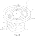
- the invention may involve a multi-axis centrifuge 5 as shown in Figs. 1 and 2 , and this description will refer to X, Y, and Z axes, as shown, as well as the planes that these axes define, i.e., the X-Y plane, the X-Z plane and the Y-Z plane.
- Centrifuge 5 may be made of structural materials of any type such as metal or engineering polymers and may be operated by a mechanical drive using electrical motors 14, 22, and 32 of any type as shown and described. Alternately, centrifuge 5 may be operated by fluidic drives, magnetic drives or other well-known drive types.
- Motor 14 may be enclosed within a stationary base 12 may be joined to operate a centrally located hub 15 in rotation about the Z axis as shown in Fig. 1 .
- a pair of colinear arms 16 may be joined to, and rotate with, hub 15 in parallel with the X-Y plane as also shown in Fig. 1 .
- a pair of rods or struts 18 may extend from arms 16 in support of an outer ring 10 which may lie in the X-Y plane as shown.
- An inner ring 20 may be positioned concentric with outer ring 10 as shown and further may be joined by motor 22 having a bearing set 24 and axle 26 to outer ring 10.
- outer ring 10 may be eliminated, and instead, in a further embodiment, simply arranged to have inner ring 20, motor 22 with its bearing set 24, and 20 axle 26 supported directly by struts 18.
- motor 22 may simultaneously rotate inner ring 20.
- a spherical capsule 40 may be positioned centrally and concentrically within both inner ring 20 and outer ring 10.
- Capsule 40 may be hollow so that it may have an interior surface which may be spherical or may have any other shape whatsoever.
- Capsule 40 may be engaged with inner ring 20 by axle 30, and motor 32 with its bearing set 34.
- Motor 32 may be able to drive axle 30 and capsule 40 in rotation about the Y axis.
- Motors 14, 22, and 32 may be operated independently with any one of said motors rotating or not and each motor may be operated in either rotational sense. Indeed, each motor may be adjusted to a selected rotational velocity and, additionally, each may be operated in any sequence of back and forth rotation according to a present or adjustable program.
- centrifuge 5 The primary objective of centrifuge 5 is the separation of fluid, semi-solid, or solid species as described in the preceding Background. Such species shall be referred to herein as comprised of "particles" which may be small pieces of solid materials, molecules, gaseous or liquid elements, or atomic particles.
- a further objective may be achieved by applying back and forth agitation programs which can result in the beneficial mixing of species having similar masses while those of differing masses are separated. With effective separation by high speed spinning of capsule 40, interposed with rotational agitation for mixing, both may be accomplished simultaneously.
- the spinning of capsule 40 about only the Y axis using motor 32 may result in separating a material with a gradation of particle masses with heavier masses moving toward the interior surface of capsule 40 forming a torus shape or a flat band, i.e., a ring, of heavy mass particles and such a ring will be circumscribed about the Y axis and lie in the X-Z plane.
- the ring may have a cross-sectional shape associated with a gaussian profile, that is; the probability density function of a normally distributed random variable.
- the center may be aligned with the XZ plane. With higher rotational speeds, the center magnitude may increase and the value of sigma, a measure of the spread, may diminish, i.e., the width of the ring may decrease.
- Figs. 1 and 2 represent electrical conductors. Electrical power may be fed into base 12 by a power line (not shown) or base 12 may contain an electrical energy storage battery (not shown). Electrical power may be fed to motors 14, 22, and 32 separately as is well known in the art through sliding electrical contractors.
- a controller (not shown), such as a common industrial motor controller may be used to operate motors 14, 22, and 32 as to their speed and operating program, as is also well known in the art.
Landscapes
- Centrifugal Separators (AREA)
Description
- The present invention generally relates to separation of fluids and more specifically to mechanical methods, apparatus, and systems for separating fluids.
- Generally, a centrifuge is an apparatus that puts an object in rotation around a fixed axis, applying a potentially strong radial force perpendicular to the axis of spin. The centrifuge works using the sedimentation principle, where centripetal acceleration causes denser substances and particles that are held within the spinning container, to move outward in the radial direction. At the same time, objects that are less dense are displaced and forced toward the axis of spin. In a laboratory centrifuge that uses sample tubes, the radial acceleration causes denser particles to settle to the bottom of the tube, while low-density substances rise to the top. There are three types of centrifuge designed for different applications. Industrial scale centrifuges are commonly used in manufacturing and waste processing to sediment suspended solids, or to separate immiscible liquids. An example is the cream separator found in dairies. Very highspeed centrifuges and ultracentrifuges are able to provide very high accelerations separating fine particles down to the nano-scale, and also molecules of different masses. Gas centrifuges are used for isotope separation, such as to enrich nuclear fuel to obtain fissile isotopes.
- A wide variety of laboratory-scale centrifuges are used in chemistry, biology, biochemistry and clinical medicine for isolating and separating suspensions and various fluid substances. Embodiments of the present invention may be used in any industry. They vary widely in speed, capacity, temperature control, and other characteristics. Laboratory centrifuges often can accept a range of different fixed-angle and swinging bucket rotors able to carry different numbers of centrifuge tubes and rated for specific maximum speeds. Controls vary from simple electrical timers to programmable models able to control acceleration and deceleration rates, running speeds, and temperature regimes. Ultracentrifuges spin the rotors under vacuum, eliminating air resistance and enabling exact temperature control. Zonal rotors and continuous flow systems are capable of handling bulk and larger sample volumes, respectively, in a laboratory-scale instrument. An important application in medicine is blood separation. Blood separates into cells and proteins (RBC, WBC, platelets, etc.) and serum. DNA preparation is another common application for pharmacogenetics and clinical diagnosis. DNA samples are purified, and the DNA is prepped for separation by adding buffers and then centrifuging it for a certain amount of time. The blood waste is then removed, and another buffer is added and spun inside the centrifuge again. Once the blood waste is removed and another buffer is added the pellet can be suspended and cooled. Proteins can then be removed and with further centrifuging DNA may be isolated completely. Protocols for centrifugation typically specify the amount of acceleration to be applied to the sample, rather than specifying a rotational speed, i.e., revolutions per minute. This distinction is important because two rotors with different diameters running at the same rotational speed will subject samples to different acceleration forces.
- In circular motion, acceleration is the product of radial distance, the square of angular velocity and the acceleration relative to "g." This is traditionally referred to as "relative centrifugal force" (RCF). The acceleration is measured in multiples of "g" the standard acceleration due to gravity at the Earth's surface which is a dimensionless quantity given by the radius times the angular velocity squared and divided by "g. "
-
WO2015/069329A2 discloses spacecraft three-axis simulators having no limitation on the maximum angle of rotation.JP2017130636A US2006/293795A1 discloses a three-axis motion table capable of ensuring smooth rotations around three rotation axes orthogonal to each other and decreasing an overall weight.US486876A discloses a centrifugal extractor comprising a basket pivotally suspended in a ring.US2012/301667A1 discloses a method and apparatus for coating a complex object and composite comprising the coated object. - A centrifuge positioned in a three-axis coordinate system is provided according to claim 1.
- Other features and advantages of the present invention will be or will become apparent to one skilled in the art upon examination of the following figures and detailed description, which illustrate, by way of examples, the principles of the present invention.
- Embodiments of the present invention are illustrated only as examples in the figures of the accompanying drawing sheets wherein the same element appearing in various figures is referenced by a common reference mark.
-
Figure 1 illustrates a perspective view of the invention shown with an inner ring aligned with anouter ring 30 in an X-Y plane, according to exemplary embodiments of the present invention. -
Figure 2 illustrates a perspective view thereof shown with the outer ring rotated by 90° in the clockwise sense about a Z axis, and the inner ring is shown rotated by 90° in a counterclockwise sense about an X axis, according to exemplary embodiments of the present invention. - Disclosed herein are apparatus, methods, and systems for separating fluids. Embodiments of the present invention involve centrifugal forces to separate various fluids.
- In some embodiments, the invention may involve a multi-axis centrifuge 5 as shown in
Figs. 1 and2 , and this description will refer to X, Y, and Z axes, as shown, as well as the planes that these axes define, i.e., the X-Y plane, the X-Z plane and the Y-Z plane. Centrifuge 5 may be made of structural materials of any type such as metal or engineering polymers and may be operated by a mechanical drive usingelectrical motors Motor 14 may be enclosed within astationary base 12 may be joined to operate a centrally located hub 15 in rotation about the Z axis as shown inFig. 1 . A pair ofcolinear arms 16 may be joined to, and rotate with, hub 15 in parallel with the X-Y plane as also shown inFig. 1 . A pair of rods orstruts 18 may extend fromarms 16 in support of an outer ring 10 which may lie in the X-Y plane as shown. Aninner ring 20 may be positioned concentric with outer ring 10 as shown and further may be joined bymotor 22 having a bearing set 24 andaxle 26 to outer ring 10. - It should be clear to those of skill in the art that outer ring 10 may be eliminated, and instead, in a further embodiment, simply arranged to have
inner ring 20,motor 22 with itsbearing set 24, and 20axle 26 supported directly bystruts 18. - It should be understood that as hub 15 and outer ring 10 rotate,
motor 22 may simultaneously rotateinner ring 20. - As shown in the figures, a
spherical capsule 40 may be positioned centrally and concentrically within bothinner ring 20 and outer ring 10. Capsule 40 may be hollow so that it may have an interior surface which may be spherical or may have any other shape whatsoever. Capsule 40 may be engaged withinner ring 20 byaxle 30, andmotor 32 with its bearing set 34.Motor 32 may be able to driveaxle 30 andcapsule 40 in rotation about the Y axis. - Motors 14, 22, and 32 may be operated independently with any one of said motors rotating or not and each motor may be operated in either rotational sense. Indeed, each motor may be adjusted to a selected rotational velocity and, additionally, each may be operated in any sequence of back and forth rotation according to a present or adjustable program.
- The primary objective of centrifuge 5 is the separation of fluid, semi-solid, or solid species as described in the preceding Background. Such species shall be referred to herein as comprised of "particles" which may be small pieces of solid materials, molecules, gaseous or liquid elements, or atomic particles. A further objective may be achieved by applying back and forth agitation programs which can result in the beneficial mixing of species having similar masses while those of differing masses are separated. With effective separation by high speed spinning of
capsule 40, interposed with rotational agitation for mixing, both may be accomplished simultaneously. - It should be recognized that the spinning of
capsule 40 about only the Yaxis using motor 32 may result in separating a material with a gradation of particle masses with heavier masses moving toward the interior surface ofcapsule 40 forming a torus shape or a flat band, i.e., a ring, of heavy mass particles and such a ring will be circumscribed about the Y axis and lie in the X-Z plane. The ring may have a cross-sectional shape associated with a gaussian profile, that is; the probability density function of a normally distributed random variable. The center may be aligned with the XZ plane. With higher rotational speeds, the center magnitude may increase and the value of sigma, a measure of the spread, may diminish, i.e., the width of the ring may decrease. - Alternately, if in addition to the rotation of
motor 32,motor 22 were to also be operated causing rotation ofinner ring 20, heavier mass particles may tend to migrate not only to a ring lying in the X-Z plane, but also to form a ring lying in the Y-Z plane. Assuming the velocities ofmotors - In the same manner as described above, when
motors capsule 40. However, as motor rotation increases, separate rings may tend to grow in alignment with the three respective planes X-Y, X-Z, and Y-Z, and at significant rotational velocities, three distinct rings of heavier mass particles will form against the interior surface ofcapsule 40 while lighter mas particles may tend to align within the interior of each of the three rings with the lightest mass particles positioned at the center. - It is well known in the art to disassemble a centrifuge container such as
capsule 40 to retrieve separated materials. This could be accomplished by removingcapsule 40 fromaxle 30 and then separate the two hemispheres to acquire the materials within. - The dashed lines in
Figs. 1 and2 represent electrical conductors. Electrical power may be fed intobase 12 by a power line (not shown) orbase 12 may contain an electrical energy storage battery (not shown). Electrical power may be fed tomotors motors - In the foregoing description, embodiments are described as a plurality of individual parts, this is solely for the sake of illustration. Accordingly, the sense and understanding of the apparatus is defined by the scope of the appended claims.
Claims (12)
- A centrifuge (5) positioned in a three-axis coordinate system,comprising: a mechanical drive (14, 22, 32);a capsule engaged with the mechanical drive wherein the capsule is engaged with the mechanical drive to rotate about mutually orthogonal X, Y, and Z axis of the three-axis coordinate system,characterized in that the capsule is hollow, and has a spherical interior surface, wherein spinning the capsule results in heavy mass particles moving toward the spherical interior surface and particles are retrieved through disassembly of the capsule.
- The centrifuge of claim 1 further comprising a stationary base having a first motor (14) of the mechanical drive, wherein the first motor operates a centrally located hub (15) in rotation about said Z axis.
- The centrifuge of claim 2 wherein the hub has a pair of colinear arms (16) oriented in parallel with an X-Y plane of the three-axis coordinate system.
- The centrifuge of claim 3 further comprising a pair of struts (18) extending from the colinear arms, the struts supporting an outer ring (10).
- The centrifuge of claim 4 further comprising an inner ring (20) positioned concentric with the outer ring.
- The centrifuge of claim 5 further comprising a second motor (22) of the mechanical drive, wherein the second motor is engaged with the said outer ring and the inner ring and enabled for rotating the inner ring relative to the outer ring about the X axis.
- The centrifuge of claim 6 further comprising a third motor (32) of the mechanical drive, wherein the third motor is engaged with both the inner ring and the capsule wherein the third motor is enabled for rotating the capsule relative to the inner ring about the Y axis.
- The centrifuge of claim 3 further comprising a pair of struts (18) extending from the colinear arms, the struts supporting a second motor (22) of said mechanical drive, wherein the second motor is engaged with an inner ring and enabled for rotating the inner ring relative to the struts about the X axis.
- The centrifuge of claim 8 further comprising a third motor (32) of the mechanical drive, wherein the third motor is engaged with both the inner ring and the capsule, and wherein the third motor is enabled for rotating the capsule relative to the inner ring about the Y axis.
- The centrifuge of claim 9 wherein the first, second, and third motors are operable independently or simultaneously.
- The centrifuge of claim 1 wherein the capsule spins about at least one of said axes.
- The centrifuge of claim 1, wherein the capsule spins about the three axes of the coordinate system at a rotational rate enabling the production of three axially distinct rings of heavy mass particles, each axially distinct ring of heavy mass particles being aligned with a respective plane.
Applications Claiming Priority (2)
| Application Number | Priority Date | Filing Date | Title |
|---|---|---|---|
| US15/949,089 US11000858B2 (en) | 2018-04-10 | 2018-04-10 | Multi-axis centrifuge |
| PCT/US2019/026793 WO2019199975A1 (en) | 2018-04-10 | 2019-04-10 | Separation of fluids |
Publications (4)
| Publication Number | Publication Date |
|---|---|
| EP3774063A1 EP3774063A1 (en) | 2021-02-17 |
| EP3774063A4 EP3774063A4 (en) | 2022-02-16 |
| EP3774063C0 EP3774063C0 (en) | 2024-09-11 |
| EP3774063B1 true EP3774063B1 (en) | 2024-09-11 |
Family
ID=68164546
Family Applications (1)
| Application Number | Title | Priority Date | Filing Date |
|---|---|---|---|
| EP19784689.2A Active EP3774063B1 (en) | 2018-04-10 | 2019-04-10 | Separation of fluids |
Country Status (3)
| Country | Link |
|---|---|
| US (2) | US11000858B2 (en) |
| EP (1) | EP3774063B1 (en) |
| WO (1) | WO2019199975A1 (en) |
Families Citing this family (3)
| Publication number | Priority date | Publication date | Assignee | Title |
|---|---|---|---|---|
| KR102318501B1 (en) * | 2018-08-21 | 2021-10-28 | 주식회사 엘지화학 | Solid Phase Extraction Using Micro device |
| CN113909002B (en) * | 2021-09-30 | 2026-05-08 | 宁合科技服务(南京)有限公司 | A type of oscillating centrifuge device |
| US12403482B1 (en) * | 2025-05-01 | 2025-09-02 | Joseph Largey | Continuous clean centrifuge |
Family Cites Families (22)
| Publication number | Priority date | Publication date | Assignee | Title |
|---|---|---|---|---|
| US486876A (en) * | 1892-11-29 | William everett johnson | ||
| GB861318A (en) | 1956-04-06 | 1961-02-15 | V & E Plastics Ltd | Improvements in or relating to the manufacture of hollow inflated plastic objects |
| US3275733A (en) | 1963-01-02 | 1966-09-27 | Allied Chem | Process for the production of hollow articles of polymerized lactams |
| US3347971A (en) | 1963-06-17 | 1967-10-17 | Uniroyal Inc | Rotational molding |
| FR1422892A (en) | 1964-09-08 | 1966-01-03 | Bertin & Cie | Improvements to test machines allowing pilots to be subjected to acceleration, in particular, when moving on a circular path |
| US3652760A (en) | 1969-01-15 | 1972-03-28 | Spheres Inc | Process for casting acrylic spheres |
| GB1254090A (en) | 1969-04-04 | 1971-11-17 | Mitsubishi Petrochemical Co | Rotational moulding |
| US3788392A (en) | 1971-07-06 | 1974-01-29 | Fmc Corp | Revolving linear tube heat exchanger |
| US4104357A (en) | 1973-01-10 | 1978-08-01 | Monster Molding, Inc. | Method of rotational molding about plural axes at low rotational speeds |
| US3841165A (en) | 1973-05-16 | 1974-10-15 | J Layfield | Motion converter |
| US3929182A (en) | 1973-11-05 | 1975-12-30 | Jr Juan Jose Amado | Method of centrifugally casting hollow spheres |
| US4050875A (en) | 1975-12-04 | 1977-09-27 | Marvin Glass & Associates | Arts and crafts molding device |
| US7241114B2 (en) | 2002-10-30 | 2007-07-10 | Siemens Ag | Rotor for a centrifugal pump |
| JP2004340718A (en) * | 2003-05-15 | 2004-12-02 | Univ Nihon | 3-axis motion table |
| FR2928099A1 (en) * | 2008-02-28 | 2009-09-04 | Cie Euro Etude Rech Paroscopie | METHOD FOR MANUFACTURING A FLEXIBLE POCKET |
| CA2837024C (en) * | 2011-05-23 | 2019-06-25 | Amst-Systemtechnik Gmbh | Device and method for simulating accelerations |
| WO2012162642A2 (en) * | 2011-05-26 | 2012-11-29 | Advenira Enterprises, Inc. | System and process for coating an object |
| US9457398B2 (en) | 2011-06-10 | 2016-10-04 | Jean-Paul Ciardullo | Spherical centrifuge |
| US10621883B2 (en) * | 2013-08-13 | 2020-04-14 | The Regents Of The University Of California | Angularly unbounded three-axis spacecraft simulator |
| DE102015209800B4 (en) | 2015-05-28 | 2025-09-04 | Adidas Ag | Method for producing a three-dimensional composite article |
| GB2543815A (en) | 2015-10-30 | 2017-05-03 | Brian Duffus Leggat James | Three dimensional centrifuge |
| JP6293173B2 (en) * | 2016-01-22 | 2018-03-14 | 株式会社メルビル | Demagnetizing rotating device |
-
2018
- 2018-04-10 US US15/949,089 patent/US11000858B2/en active Active
-
2019
- 2019-04-10 WO PCT/US2019/026793 patent/WO2019199975A1/en not_active Ceased
- 2019-04-10 EP EP19784689.2A patent/EP3774063B1/en active Active
-
2021
- 2021-03-09 US US17/196,941 patent/US20210197212A1/en not_active Abandoned
Also Published As
| Publication number | Publication date |
|---|---|
| EP3774063C0 (en) | 2024-09-11 |
| US20210060580A1 (en) | 2021-03-04 |
| EP3774063A4 (en) | 2022-02-16 |
| EP3774063A1 (en) | 2021-02-17 |
| US20210197212A1 (en) | 2021-07-01 |
| US11000858B2 (en) | 2021-05-11 |
| WO2019199975A1 (en) | 2019-10-17 |
Similar Documents
| Publication | Publication Date | Title |
|---|---|---|
| US20210197212A1 (en) | Multi-axis centrifuge | |
| Anderson | The zonal ultracentrifuge. A new instrument for fractionating mixtures of particles | |
| US20210316299A1 (en) | Device and method for fluids separation by density gradient | |
| WO2003045568A1 (en) | Centrifuge with removable core for scalable centrifugation | |
| US4341343A (en) | Magnetically driven centrifuge system | |
| Olatunde et al. | Centrifugation techniques | |
| EP3349897A1 (en) | Device and method for fluids separation by density gradient | |
| JP2014505675A5 (en) | ||
| US2878994A (en) | Centrifuge tube and method of centrifuging | |
| Sood et al. | Centrifugation: Basic principle, types | |
| US8033976B2 (en) | Apparatus and method for centrifugal separation utilizing a movable collection assembly | |
| EP3784409B1 (en) | Centrifuge operating with sinusoidal motions | |
| US5605529A (en) | High efficiency centrifuge rotor | |
| US3326459A (en) | Particle classifier | |
| JP7557730B2 (en) | Separation of particles by centrifugal sedimentation | |
| Griffith | Practical techniques for centrifugal separations | |
| CN219150423U (en) | Balancing centrifuge tube for centrifuge, centrifuge tube kit and centrifuge | |
| Gandhi et al. | Centrifugation | |
| Hu et al. | Centrifugation | |
| CN110339948A (en) | A kind of slow-speed of revolution minitype particle separator | |
| CN116020667A (en) | Trim Tubes, Tube Kits and Centrifuges for Centrifuges | |
| Plate | DN Taulbee and M. Mercedes Maroto-Valer | |
| BR112022001429B1 (en) | METHOD OF PARTICLE SEPARATION AND APPARATUS | |
| CN120605816A (en) | Variable-angle high-speed centrifugal construction device and its application | |
| Lewin | Centrifuges |
Legal Events
| Date | Code | Title | Description |
|---|---|---|---|
| STAA | Information on the status of an ep patent application or granted ep patent |
Free format text: STATUS: THE INTERNATIONAL PUBLICATION HAS BEEN MADE |
|
| PUAI | Public reference made under article 153(3) epc to a published international application that has entered the european phase |
Free format text: ORIGINAL CODE: 0009012 |
|
| STAA | Information on the status of an ep patent application or granted ep patent |
Free format text: STATUS: REQUEST FOR EXAMINATION WAS MADE |
|
| 17P | Request for examination filed |
Effective date: 20201012 |
|
| AK | Designated contracting states |
Kind code of ref document: A1 Designated state(s): AL AT BE BG CH CY CZ DE DK EE ES FI FR GB GR HR HU IE IS IT LI LT LU LV MC MK MT NL NO PL PT RO RS SE SI SK SM TR |
|
| AX | Request for extension of the european patent |
Extension state: BA ME |
|
| DAV | Request for validation of the european patent (deleted) | ||
| DAX | Request for extension of the european patent (deleted) | ||
| REG | Reference to a national code |
Ref country code: DE Free format text: PREVIOUS MAIN CLASS: B04B0009020000 Ref legal event code: R079 Ref document number: 602019058755 Country of ref document: DE Ipc: B04B0009000000 |
|
| A4 | Supplementary search report drawn up and despatched |
Effective date: 20220114 |
|
| RIC1 | Information provided on ipc code assigned before grant |
Ipc: B29C 41/06 20060101ALI20220110BHEP Ipc: B01D 59/20 20060101ALI20220110BHEP Ipc: B04B 1/00 20060101ALI20220110BHEP Ipc: B04B 7/08 20060101ALI20220110BHEP Ipc: B04B 9/12 20060101ALI20220110BHEP Ipc: B04B 9/08 20060101ALI20220110BHEP Ipc: B04B 9/04 20060101ALI20220110BHEP Ipc: B04B 9/00 20060101AFI20220110BHEP |
|
| GRAP | Despatch of communication of intention to grant a patent |
Free format text: ORIGINAL CODE: EPIDOSNIGR1 |
|
| STAA | Information on the status of an ep patent application or granted ep patent |
Free format text: STATUS: GRANT OF PATENT IS INTENDED |
|
| INTG | Intention to grant announced |
Effective date: 20240403 |
|
| GRAS | Grant fee paid |
Free format text: ORIGINAL CODE: EPIDOSNIGR3 |
|
| GRAA | (expected) grant |
Free format text: ORIGINAL CODE: 0009210 |
|
| STAA | Information on the status of an ep patent application or granted ep patent |
Free format text: STATUS: THE PATENT HAS BEEN GRANTED |
|
| AK | Designated contracting states |
Kind code of ref document: B1 Designated state(s): AL AT BE BG CH CY CZ DE DK EE ES FI FR GB GR HR HU IE IS IT LI LT LU LV MC MK MT NL NO PL PT RO RS SE SI SK SM TR |
|
| REG | Reference to a national code |
Ref country code: GB Ref legal event code: FG4D |
|
| REG | Reference to a national code |
Ref country code: CH Ref legal event code: EP |
|
| REG | Reference to a national code |
Ref country code: DE Ref legal event code: R096 Ref document number: 602019058755 Country of ref document: DE |
|
| REG | Reference to a national code |
Ref country code: IE Ref legal event code: FG4D |
|
| U01 | Request for unitary effect filed |
Effective date: 20240923 |
|
| U07 | Unitary effect registered |
Designated state(s): AT BE BG DE DK EE FI FR IT LT LU LV MT NL PT RO SE SI Effective date: 20241016 |
|
| PG25 | Lapsed in a contracting state [announced via postgrant information from national office to epo] |
Ref country code: NO Free format text: LAPSE BECAUSE OF FAILURE TO SUBMIT A TRANSLATION OF THE DESCRIPTION OR TO PAY THE FEE WITHIN THE PRESCRIBED TIME-LIMIT Effective date: 20241211 |
|
| PG25 | Lapsed in a contracting state [announced via postgrant information from national office to epo] |
Ref country code: GR Free format text: LAPSE BECAUSE OF FAILURE TO SUBMIT A TRANSLATION OF THE DESCRIPTION OR TO PAY THE FEE WITHIN THE PRESCRIBED TIME-LIMIT Effective date: 20241212 |
|
| PG25 | Lapsed in a contracting state [announced via postgrant information from national office to epo] |
Ref country code: HR Free format text: LAPSE BECAUSE OF FAILURE TO SUBMIT A TRANSLATION OF THE DESCRIPTION OR TO PAY THE FEE WITHIN THE PRESCRIBED TIME-LIMIT Effective date: 20240911 |
|
| PG25 | Lapsed in a contracting state [announced via postgrant information from national office to epo] |
Ref country code: RS Free format text: LAPSE BECAUSE OF FAILURE TO SUBMIT A TRANSLATION OF THE DESCRIPTION OR TO PAY THE FEE WITHIN THE PRESCRIBED TIME-LIMIT Effective date: 20241211 Ref country code: ES Free format text: LAPSE BECAUSE OF FAILURE TO SUBMIT A TRANSLATION OF THE DESCRIPTION OR TO PAY THE FEE WITHIN THE PRESCRIBED TIME-LIMIT Effective date: 20240911 |
|
| PG25 | Lapsed in a contracting state [announced via postgrant information from national office to epo] |
Ref country code: RS Free format text: LAPSE BECAUSE OF FAILURE TO SUBMIT A TRANSLATION OF THE DESCRIPTION OR TO PAY THE FEE WITHIN THE PRESCRIBED TIME-LIMIT Effective date: 20241211 Ref country code: NO Free format text: LAPSE BECAUSE OF FAILURE TO SUBMIT A TRANSLATION OF THE DESCRIPTION OR TO PAY THE FEE WITHIN THE PRESCRIBED TIME-LIMIT Effective date: 20241211 Ref country code: HR Free format text: LAPSE BECAUSE OF FAILURE TO SUBMIT A TRANSLATION OF THE DESCRIPTION OR TO PAY THE FEE WITHIN THE PRESCRIBED TIME-LIMIT Effective date: 20240911 Ref country code: GR Free format text: LAPSE BECAUSE OF FAILURE TO SUBMIT A TRANSLATION OF THE DESCRIPTION OR TO PAY THE FEE WITHIN THE PRESCRIBED TIME-LIMIT Effective date: 20241212 Ref country code: ES Free format text: LAPSE BECAUSE OF FAILURE TO SUBMIT A TRANSLATION OF THE DESCRIPTION OR TO PAY THE FEE WITHIN THE PRESCRIBED TIME-LIMIT Effective date: 20240911 |
|
| PG25 | Lapsed in a contracting state [announced via postgrant information from national office to epo] |
Ref country code: IS Free format text: LAPSE BECAUSE OF FAILURE TO SUBMIT A TRANSLATION OF THE DESCRIPTION OR TO PAY THE FEE WITHIN THE PRESCRIBED TIME-LIMIT Effective date: 20250111 |
|
| PG25 | Lapsed in a contracting state [announced via postgrant information from national office to epo] |
Ref country code: SM Free format text: LAPSE BECAUSE OF FAILURE TO SUBMIT A TRANSLATION OF THE DESCRIPTION OR TO PAY THE FEE WITHIN THE PRESCRIBED TIME-LIMIT Effective date: 20240911 |
|
| PG25 | Lapsed in a contracting state [announced via postgrant information from national office to epo] |
Ref country code: CZ Free format text: LAPSE BECAUSE OF FAILURE TO SUBMIT A TRANSLATION OF THE DESCRIPTION OR TO PAY THE FEE WITHIN THE PRESCRIBED TIME-LIMIT Effective date: 20240911 Ref country code: PL Free format text: LAPSE BECAUSE OF FAILURE TO SUBMIT A TRANSLATION OF THE DESCRIPTION OR TO PAY THE FEE WITHIN THE PRESCRIBED TIME-LIMIT Effective date: 20240911 |
|
| PG25 | Lapsed in a contracting state [announced via postgrant information from national office to epo] |
Ref country code: SK Free format text: LAPSE BECAUSE OF FAILURE TO SUBMIT A TRANSLATION OF THE DESCRIPTION OR TO PAY THE FEE WITHIN THE PRESCRIBED TIME-LIMIT Effective date: 20240911 |
|
| U20 | Renewal fee for the european patent with unitary effect paid |
Year of fee payment: 7 Effective date: 20250416 |
|
| PLBE | No opposition filed within time limit |
Free format text: ORIGINAL CODE: 0009261 |
|
| STAA | Information on the status of an ep patent application or granted ep patent |
Free format text: STATUS: NO OPPOSITION FILED WITHIN TIME LIMIT |
|
| 26N | No opposition filed |
Effective date: 20250612 |
|
| REG | Reference to a national code |
Ref country code: CH Ref legal event code: H13 Free format text: ST27 STATUS EVENT CODE: U-0-0-H10-H13 (AS PROVIDED BY THE NATIONAL OFFICE) Effective date: 20251125 |
|
| PG25 | Lapsed in a contracting state [announced via postgrant information from national office to epo] |
Ref country code: MC Free format text: LAPSE BECAUSE OF FAILURE TO SUBMIT A TRANSLATION OF THE DESCRIPTION OR TO PAY THE FEE WITHIN THE PRESCRIBED TIME-LIMIT Effective date: 20240911 |
|
| PG25 | Lapsed in a contracting state [announced via postgrant information from national office to epo] |
Ref country code: CH Free format text: LAPSE BECAUSE OF NON-PAYMENT OF DUE FEES Effective date: 20250430 |
|
| U20 | Renewal fee for the european patent with unitary effect paid |
Year of fee payment: 8 Effective date: 20260305 |
|
| PGFP | Annual fee paid to national office [announced via postgrant information from national office to epo] |
Ref country code: GB Payment date: 20260305 Year of fee payment: 8 |
|
| PG25 | Lapsed in a contracting state [announced via postgrant information from national office to epo] |
Ref country code: IE Free format text: LAPSE BECAUSE OF NON-PAYMENT OF DUE FEES Effective date: 20250410 |
|
| PG25 | Lapsed in a contracting state [announced via postgrant information from national office to epo] |
Ref country code: CY Free format text: LAPSE BECAUSE OF FAILURE TO SUBMIT A TRANSLATION OF THE DESCRIPTION OR TO PAY THE FEE WITHIN THE PRESCRIBED TIME-LIMIT Effective date: 20240911 |