EP3773974B1 - Stormwater drain insert - Google Patents
Stormwater drain insert Download PDFInfo
- Publication number
- EP3773974B1 EP3773974B1 EP19715346.3A EP19715346A EP3773974B1 EP 3773974 B1 EP3773974 B1 EP 3773974B1 EP 19715346 A EP19715346 A EP 19715346A EP 3773974 B1 EP3773974 B1 EP 3773974B1
- Authority
- EP
- European Patent Office
- Prior art keywords
- drain insert
- stormwater drain
- sediment bag
- stormwater
- sediment
- Prior art date
- Legal status (The legal status is an assumption and is not a legal conclusion. Google has not performed a legal analysis and makes no representation as to the accuracy of the status listed.)
- Active
Links
Images



Classifications
-
- E—FIXED CONSTRUCTIONS
- E03—WATER SUPPLY; SEWERAGE
- E03F—SEWERS; CESSPOOLS
- E03F5/00—Sewerage structures
- E03F5/14—Devices for separating liquid or solid substances from sewage, e.g. sand or sludge traps, rakes or grates
- E03F5/16—Devices for separating oil, water or grease from sewage in drains leading to the main sewer
-
- E—FIXED CONSTRUCTIONS
- E03—WATER SUPPLY; SEWERAGE
- E03F—SEWERS; CESSPOOLS
- E03F5/00—Sewerage structures
- E03F5/04—Gullies inlets, road sinks, floor drains with or without odour seals or sediment traps
- E03F5/0401—Gullies for use in roads or pavements
- E03F5/0404—Gullies for use in roads or pavements with a permanent or temporary filtering device; Filtering devices specially adapted therefor
-
- B—PERFORMING OPERATIONS; TRANSPORTING
- B01—PHYSICAL OR CHEMICAL PROCESSES OR APPARATUS IN GENERAL
- B01D—SEPARATION
- B01D15/00—Separating processes involving the treatment of liquids with solid sorbents; Apparatus therefor
-
- B—PERFORMING OPERATIONS; TRANSPORTING
- B01—PHYSICAL OR CHEMICAL PROCESSES OR APPARATUS IN GENERAL
- B01D—SEPARATION
- B01D29/00—Filters with filtering elements stationary during filtration, e.g. pressure or suction filters, not covered by groups B01D24/00 - B01D27/00; Filtering elements therefor
- B01D29/11—Filters with filtering elements stationary during filtration, e.g. pressure or suction filters, not covered by groups B01D24/00 - B01D27/00; Filtering elements therefor with bag, cage, hose, tube, sleeve or like filtering elements
- B01D29/13—Supported filter elements
- B01D29/23—Supported filter elements arranged for outward flow filtration
-
- B—PERFORMING OPERATIONS; TRANSPORTING
- B01—PHYSICAL OR CHEMICAL PROCESSES OR APPARATUS IN GENERAL
- B01D—SEPARATION
- B01D29/00—Filters with filtering elements stationary during filtration, e.g. pressure or suction filters, not covered by groups B01D24/00 - B01D27/00; Filtering elements therefor
- B01D29/11—Filters with filtering elements stationary during filtration, e.g. pressure or suction filters, not covered by groups B01D24/00 - B01D27/00; Filtering elements therefor with bag, cage, hose, tube, sleeve or like filtering elements
- B01D29/13—Supported filter elements
- B01D29/23—Supported filter elements arranged for outward flow filtration
- B01D29/27—Filter bags
-
- C—CHEMISTRY; METALLURGY
- C02—TREATMENT OF WATER, WASTE WATER, SEWAGE, OR SLUDGE
- C02F—TREATMENT OF WATER, WASTE WATER, SEWAGE, OR SLUDGE
- C02F1/00—Treatment of water, waste water, or sewage
- C02F1/001—Processes for the treatment of water whereby the filtration technique is of importance
- C02F1/004—Processes for the treatment of water whereby the filtration technique is of importance using large scale industrial sized filters
-
- C—CHEMISTRY; METALLURGY
- C02—TREATMENT OF WATER, WASTE WATER, SEWAGE, OR SLUDGE
- C02F—TREATMENT OF WATER, WASTE WATER, SEWAGE, OR SLUDGE
- C02F1/00—Treatment of water, waste water, or sewage
- C02F1/28—Treatment of water, waste water, or sewage by sorption
- C02F1/285—Treatment of water, waste water, or sewage by sorption using synthetic organic sorbents
-
- E—FIXED CONSTRUCTIONS
- E03—WATER SUPPLY; SEWERAGE
- E03F—SEWERS; CESSPOOLS
- E03F5/00—Sewerage structures
- E03F5/14—Devices for separating liquid or solid substances from sewage, e.g. sand or sludge traps, rakes or grates
-
- B—PERFORMING OPERATIONS; TRANSPORTING
- B01—PHYSICAL OR CHEMICAL PROCESSES OR APPARATUS IN GENERAL
- B01D—SEPARATION
- B01D2201/00—Details relating to filtering apparatus
- B01D2201/48—Overflow systems
-
- C—CHEMISTRY; METALLURGY
- C02—TREATMENT OF WATER, WASTE WATER, SEWAGE, OR SLUDGE
- C02F—TREATMENT OF WATER, WASTE WATER, SEWAGE, OR SLUDGE
- C02F2101/00—Nature of the contaminant
- C02F2101/10—Inorganic compounds
- C02F2101/20—Heavy metals or heavy metal compounds
-
- C—CHEMISTRY; METALLURGY
- C02—TREATMENT OF WATER, WASTE WATER, SEWAGE, OR SLUDGE
- C02F—TREATMENT OF WATER, WASTE WATER, SEWAGE, OR SLUDGE
- C02F2101/00—Nature of the contaminant
- C02F2101/30—Organic compounds
- C02F2101/32—Hydrocarbons, e.g. oil
-
- C—CHEMISTRY; METALLURGY
- C02—TREATMENT OF WATER, WASTE WATER, SEWAGE, OR SLUDGE
- C02F—TREATMENT OF WATER, WASTE WATER, SEWAGE, OR SLUDGE
- C02F2103/00—Nature of the water, waste water, sewage or sludge to be treated
- C02F2103/001—Runoff or storm water
Definitions
- the present invention relates to stormwater drain inserts that are adjustable in size and are designed to handle overflow conditions.
- Certain types of conventional stormwater drain inserts include a layer of water permeable fabric that captures sediment and other contaminants, but allows water to pass through the fabric.
- a central sediment bag extends downwardly from a flat layer of the water permeable fabric.
- the stormwater drain inserts may be held in place within a storm chamber by the weight of a storm drain grate that presses around the periphery of the fabric layer.
- Braces may optionally be inserted through loops at edges of the fabric for additional stability. Slits or openings are provided at the outer edges or corners of the filter fabric to accommodate such braces. However, such slits and openings can allow untreated stormwater runoff to pass through.
- a circular metal rod may be located at a circular top edge of a sediment bag for added stability.
- Such rods define a specific chamber opening diameter and cannot be adjusted for different size chambers.
- US 2013/299402 discloses a stormwater drain insert according to the preamble of claim 1.
- the present invention provides stormwater drain inserts that reduce or eliminate environmental runoff during rain storms and the like.
- the stormwater drain inserts are water permeable, but capture sediment, hydrocarbons, heavy metals and other contaminants.
- the stormwater drain inserts are adjustable in size in order to fit into various sizes of storm drain chambers, resting on the lip between the top grate and the chamber.
- the stormwater drain inserts include a top bib with a central sediment bag extending downward therefrom. Overflow ports are provided in the sediment bag, and an inwardly extending overhang ring directs incoming water flow away from the overflow ports as it enters the sediment bag.
- the top bib, sediment bag and overhang ring may be made of water permeable oleophilic fabric that helps trap oils and other hydrocarbons.
- the present invention provides a stormwater drain insert according to claim 1.
- Non-essential or optional features are set out in the dependent claims.
- Figs. 1-5 illustrate a stormwater drain insert 10 in accordance with an embodiment of the present invention.
- the stormwater drain insert 10 includes an adjustable peripheral frame 12, a top bib 20 made of water permeable fabric, and a centrally located sediment bag 30 extending downwardly from the top bib 20.
- the adjustable peripheral frame 12 is contained in a continuous pocket 22 that extends around the outer peripheral edge of the top bib 20.
- the stormwater drain insert 10 may be installed under a storm drain grate 11 within a storm drain chamber.
- the sediment bag 30 is generally cylindrical and has a top rim 31 and a bottom panel 32 or seam.
- the shape of the sediment bag 30 is slightly inwardly tapered from the top rim 31 to the bottom panel 32 or seam.
- an overhanging ring 34 is provided above the top rim 31 of the sediment bag 30 to direct the flow of water runoff, as more fully described below.
- Overflow ports 36 are provided through the sidewall of the sediment bag 30. In the embodiment shown, four overflow ports 36 are used. However, any other suitable member of overflow ports may be included, for example, two, three, five or more ports may be used. In certain embodiments, the total open area of all of the overflow ports 36 combined is at least 32 cm 2 (5 square inches), for example, at least 65cm 2 (10 square inches).
- additional fabric in the form of fingers 38 or the like may be provided inside the sediment bag 30.
- Such fingers 38 may be sewn inside the sediment bag 30 to increase the oil capturing capacity.
- the fabric of the top bib 20, sediment bag 30, overhanging ring 34 and fabric fingers 38 comprises water permeable fabric that allows water to pass therethrough but traps sediment and other contaminants such as oils, hydrocarbons, heavy metals and the like.
- the fabric may be oleophilic in order to help trap oils and other hydrocarbons.
- the oleophilic water permeable fabric of the top bib 20, sediment bag 30 and fabric fingers 38 may be composed of polypropylene having a basis weight of 271 ⁇ 34 gsm (8 ⁇ 1 ounces per square yard (osy)) and a thickness of 0.254 ⁇ 0.08 cm (0.1 ⁇ 0.033 inches).
- Such fabrics are flexible and foldable, and allow the stormwater drain inserts 10 to be folded substantially flat prior to use, e.g., during shipping and storage.
- the oleophilic water permeable fabric of the overhanging ring 34 may be composed of a polypropylene/polyester blend having a basis weight of 381 ⁇ 59 gsm (11.25 ⁇ 1.75 ounces per square yard (osy)) and a thickness of 0.47 ⁇ 0.13 cm (0.185 ⁇ 0.05 inches).
- the sediment bag 30 has a height Hs measured from the top rim 31 to the bottom panel 32.
- the height Hs may typically range from 20 to 127 cm (8 to 50 inches), for example, from 30 to 51 cm (12 to 20 inches).
- the top rim 31 of the sediment bag 30 has a diameter D T
- the bottom panel 32 or portion of the sediment bag 30 has a diameter D B when filled with sediment.
- the diameters D T and D B may be the same or different, e.g., D B may be slightly less than D T to provide a side taper angle of the sediment bag of from 1 to 15°.
- the top diameter D T may typically range from 20 to 81 cm (8 to 32 inches), for example, from 25 to 41 cm (10 to 16 inches).
- the bottom diameter D B when filled with sediment may typically range from 20 to 81 cm (8 to 32 inches), for example, from 23 to 38 cm (9 to 15 inches).
- the overhanging ring 34 has an inner diameter D R , and a ring overhang distance R O measured radially inwardly from the top rim 31.
- the inner diameter D R and overhang distance R O of the overhanging ring 34 are sized to overhang the opening of the top rim 31 of the sediment bag 30 from 1.27 to 7.62 cm (0.5 to 3 inches), for example, by a minimum of 2.54 cm (1 inch), preferably 5.08 cm (2 inches).
- the overhanging ring 34 directs the stormwater away from the overflow ports 36 and down into the sediment bag 30. Thus, only when the stormwater flow rate is greater than the flow-through-capacity of the sediment bag 30 will stormwater pass through the overflow ports 36.
- the overflow ports 36 have a height H O and width Wo, and a bottom edge located a distance H B above the bottom panel 32 or seam.
- the height H O may typically range from 2.54 to 22.86 cm (1 to 9 inches), for example from 5.08 to 15.24 cm (2 to 6 inches).
- the width Wo may typically range from 7.62 to 20.32 cm (3 to 8 inches), for example from 10.16 to 15.24 cm (4 to 6 inches).
- each overflow port opening 36 may have a circumferential length corresponding to an angle of from 25 to 65° around the circumference of the sediment bag 30.
- an enclosed pocket 22 is provided around the peripheral edge of the top bib 20 and contains the adjustable peripheral frame 12.
- strap handles 28 may be provided along opposing edges of the top bib 20, and loop handles 29 may be provided on other opposing edges of the top bib 20.
- Such handles 28 and 29 may be made of highly visible strapping materials.
- the adjustable peripheral frame 12 includes two inner telescoping frame rods 14 receiving two outer telescoping frame tubes 16.
- the telescoping action of the inner frame rods 14 and outer frame tubes 16 allows the adjustable peripheral frame 12 to extend lengthwise and widthwise in order to fit within various sizes of storm drain chambers. From a fully collapsed condition to a fully extended condition, each side of the peripheral frame 12 can almost double in size, and the area within the adjustable peripheral frame 12 may almost quadruple in size.
- frictional engagement between the inner telescoping frame rods 14 and the outer telescoping frame tubes 16 is provided in order to reduce or prevent unwanted movement of the inner arms 14 within the outer tubes 16 during usage.
- the telescoping action when adjusting to the storm drain chamber size does not cause snagging of the filter fabric of the top bib 20 and the pocket 22 that encloses the adjustable frame 12, thus eliminating the need for the edge slits in the fabric.
- the inner rods 14 and outer tubes 16 may be made of any suitable material, such as stainless steel or another corrosion resistant metal, such as brass.
- the outer surfaces of the inner rods 14 and/or the inner surfaces of the outer tubes 16 may be provided with a rough or irregular surface in order to increase drag between the rods 14 and tubes 16.
- the inner rods 14 may be threaded. This mitigates the issue of smooth rods that can self-retract back into the outer tubes due to the weight of collected sediment in the sediment bag. Self-retraction of the rods could cause the whole unit to fall into the storm basin when the grate is removed for servicing.
- Typical diameters of the inner rods 14 may be 0.635 ⁇ 0.152 cm (0.25 ⁇ 0.06 inches), or a 0.635 x 50 cm (1 ⁇ 4 x 20 inch) threaded rod.
- Typical diameters of the outer tubes 16 may be an inner diameter of 0.635 ⁇ 0.152 cm (0.25 ⁇ 0.06 inches), and an outer diameter of 1.00 ⁇ 0.152 cm (0.394 ⁇ 0.06 inches).
- Figs. 8 and 9 illustrate the stormwater drain insert 10 in an expanded configuration and a contracted configuration, respectively.
- the expanded stormwater drain insert 10 has an expanded length L E and an expanded width W E .
- the contracted stormwater drain insert 10 has a contracted length L C and a contracted width We.
- the length L C in the most contracted configuration may approach 50 percent of the expanded length L E , e.g., about 55 or 60 percent.
- the width Wc in the most contracted configuration may approach 50 percent of the expanded width W E , e.g., about 55 or 60 percent.
- the stormwater drain insert 10 may thus be adjusted in size to cover drain chamber areas of significantly different sizes.
Landscapes
- Chemical & Material Sciences (AREA)
- Hydrology & Water Resources (AREA)
- Engineering & Computer Science (AREA)
- Water Supply & Treatment (AREA)
- Life Sciences & Earth Sciences (AREA)
- Health & Medical Sciences (AREA)
- Public Health (AREA)
- Chemical Kinetics & Catalysis (AREA)
- Environmental & Geological Engineering (AREA)
- Organic Chemistry (AREA)
- Analytical Chemistry (AREA)
- Revetment (AREA)
- Sewage (AREA)
- Farming Of Fish And Shellfish (AREA)
- Bridges Or Land Bridges (AREA)
Description
- The present invention relates to stormwater drain inserts that are adjustable in size and are designed to handle overflow conditions.
- Certain types of conventional stormwater drain inserts include a layer of water permeable fabric that captures sediment and other contaminants, but allows water to pass through the fabric. In some designs, a central sediment bag extends downwardly from a flat layer of the water permeable fabric. The stormwater drain inserts may be held in place within a storm chamber by the weight of a storm drain grate that presses around the periphery of the fabric layer. Braces may optionally be inserted through loops at edges of the fabric for additional stability. Slits or openings are provided at the outer edges or corners of the filter fabric to accommodate such braces. However, such slits and openings can allow untreated stormwater runoff to pass through.
- In round stormwater drains, a circular metal rod may be located at a circular top edge of a sediment bag for added stability. Such rods define a specific chamber opening diameter and cannot be adjusted for different size chambers.
-
US 2013/299402 discloses a stormwater drain insert according to the preamble of claim 1. - The present invention provides stormwater drain inserts that reduce or eliminate environmental runoff during rain storms and the like. The stormwater drain inserts are water permeable, but capture sediment, hydrocarbons, heavy metals and other contaminants. The stormwater drain inserts are adjustable in size in order to fit into various sizes of storm drain chambers, resting on the lip between the top grate and the chamber. The stormwater drain inserts include a top bib with a central sediment bag extending downward therefrom. Overflow ports are provided in the sediment bag, and an inwardly extending overhang ring directs incoming water flow away from the overflow ports as it enters the sediment bag. The top bib, sediment bag and overhang ring may be made of water permeable oleophilic fabric that helps trap oils and other hydrocarbons.
- The present invention provides a stormwater drain insert according to claim 1. Non-essential or optional features are set out in the dependent claims.
- These and other aspects of the present invention will be more apparent from the following description.
-
-
Fig. 1 is an isometric view of a stormwater drain insert in accordance with an embodiment of the present invention. -
Fig. 2 is a top front perspective view of a stormwater drain insert in accordance with an embodiment of the present invention installed in a storm drain chamber under a storm drain grate. -
Fig. 3 is a side view of a stormwater drain insert in accordance with an embodiment of the present invention. -
Fig. 4 is a cross-sectional side view of the stormwater drain insert ofFig. 3 . -
Fig. 5 is a top view of the stormwater drain insert ofFig. 3 . -
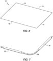
Fig. 6 is a perspective view of an adjustable frame for a stormwater drain insert in accordance with an embodiment of the present invention. -
Fig. 7 is a magnified view of a portion of the adjustable frame ofFig. 6 . -
Fig. 8 is a top view of a stormwater drain insert in an expanded configuration in accordance with an embodiment of the present invention. -
Fig. 9 is a top view of the stormwater drain insert ofFig. 8 in a collapsed configuration. -
Figs. 1-5 illustrate a stormwater drain insert 10 in accordance with an embodiment of the present invention. Thestormwater drain insert 10 includes an adjustableperipheral frame 12, atop bib 20 made of water permeable fabric, and a centrally locatedsediment bag 30 extending downwardly from thetop bib 20. The adjustableperipheral frame 12 is contained in acontinuous pocket 22 that extends around the outer peripheral edge of thetop bib 20. As shown inFig. 2 , thestormwater drain insert 10 may be installed under astorm drain grate 11 within a storm drain chamber. - As shown most clearly in
Figs. 1 ,3 and4 , thesediment bag 30 is generally cylindrical and has atop rim 31 and abottom panel 32 or seam. In the embodiment shown, the shape of thesediment bag 30 is slightly inwardly tapered from thetop rim 31 to thebottom panel 32 or seam. - As shown in
Figs. 1-5 , anoverhanging ring 34 is provided above thetop rim 31 of thesediment bag 30 to direct the flow of water runoff, as more fully described below.Overflow ports 36 are provided through the sidewall of thesediment bag 30. In the embodiment shown, fouroverflow ports 36 are used. However, any other suitable member of overflow ports may be included, for example, two, three, five or more ports may be used. In certain embodiments, the total open area of all of theoverflow ports 36 combined is at least 32 cm2 (5 square inches), for example, at least 65cm2 (10 square inches). - As shown in
Figs. 2 ,4 and 5 , additional fabric in the form offingers 38 or the like may be provided inside thesediment bag 30.Such fingers 38 may be sewn inside thesediment bag 30 to increase the oil capturing capacity. - In certain embodiments, the fabric of the
top bib 20,sediment bag 30, overhangingring 34 andfabric fingers 38 comprises water permeable fabric that allows water to pass therethrough but traps sediment and other contaminants such as oils, hydrocarbons, heavy metals and the like. The fabric may be oleophilic in order to help trap oils and other hydrocarbons. For example, the oleophilic water permeable fabric of thetop bib 20,sediment bag 30 andfabric fingers 38 may be composed of polypropylene having a basis weight of 271 ±34 gsm (8 ±1 ounces per square yard (osy)) and a thickness of 0.254 ±0.08 cm (0.1 ±0.033 inches). Such fabrics are flexible and foldable, and allow thestormwater drain inserts 10 to be folded substantially flat prior to use, e.g., during shipping and storage. - The oleophilic water permeable fabric of the overhanging
ring 34 may be composed of a polypropylene/polyester blend having a basis weight of 381 ±59 gsm (11.25 ±1.75 ounces per square yard (osy)) and a thickness of 0.47 ±0.13 cm (0.185 ±0.05 inches). - As shown in the sectional view of
Fig. 4 , thesediment bag 30 has a height Hs measured from thetop rim 31 to thebottom panel 32. The height Hs may typically range from 20 to 127 cm (8 to 50 inches), for example, from 30 to 51 cm (12 to 20 inches). As further shown inFig. 4 , thetop rim 31 of thesediment bag 30 has a diameter DT, while thebottom panel 32 or portion of thesediment bag 30 has a diameter DB when filled with sediment. The diameters DT and DB may be the same or different, e.g., DB may be slightly less than DT to provide a side taper angle of the sediment bag of from 1 to 15°. The top diameter DT may typically range from 20 to 81 cm (8 to 32 inches), for example, from 25 to 41 cm (10 to 16 inches). The bottom diameter DB when filled with sediment may typically range from 20 to 81 cm (8 to 32 inches), for example, from 23 to 38 cm (9 to 15 inches). - The overhanging
ring 34 has an inner diameter DR, and a ring overhang distance RO measured radially inwardly from thetop rim 31. The inner diameter DR and overhang distance RO of the overhangingring 34 are sized to overhang the opening of thetop rim 31 of thesediment bag 30 from 1.27 to 7.62 cm (0.5 to 3 inches), for example, by a minimum of 2.54 cm (1 inch), preferably 5.08 cm (2 inches). The overhangingring 34 directs the stormwater away from theoverflow ports 36 and down into thesediment bag 30. Thus, only when the stormwater flow rate is greater than the flow-through-capacity of thesediment bag 30 will stormwater pass through theoverflow ports 36. - The
overflow ports 36 have a height HO and width Wo, and a bottom edge located a distance HB above thebottom panel 32 or seam. The height HO may typically range from 2.54 to 22.86 cm (1 to 9 inches), for example from 5.08 to 15.24 cm (2 to 6 inches). The width Wo may typically range from 7.62 to 20.32 cm (3 to 8 inches), for example from 10.16 to 15.24 cm (4 to 6 inches). - The widths Wo of the
overflow ports 36 may be measured around the circumference of thesediment bag 30. For example, eachoverflow port opening 36 may have a circumferential length corresponding to an angle of from 25 to 65° around the circumference of thesediment bag 30. - As shown in
Figs. 1 and3-5 , anenclosed pocket 22 is provided around the peripheral edge of thetop bib 20 and contains the adjustableperipheral frame 12. As shown inFig. 2 , strap handles 28 may be provided along opposing edges of thetop bib 20, and loop handles 29 may be provided on other opposing edges of thetop bib 20.Such handles - Details of an adjustable
peripheral frame 12 in accordance with an embodiment of the present invention are shown inFigs. 6 and 7 . The adjustableperipheral frame 12 includes two innertelescoping frame rods 14 receiving two outertelescoping frame tubes 16. The telescoping action of theinner frame rods 14 andouter frame tubes 16 allows the adjustableperipheral frame 12 to extend lengthwise and widthwise in order to fit within various sizes of storm drain chambers. From a fully collapsed condition to a fully extended condition, each side of theperipheral frame 12 can almost double in size, and the area within the adjustableperipheral frame 12 may almost quadruple in size. As more fully described below, frictional engagement between the innertelescoping frame rods 14 and the outertelescoping frame tubes 16 is provided in order to reduce or prevent unwanted movement of theinner arms 14 within theouter tubes 16 during usage. - The telescoping action when adjusting to the storm drain chamber size does not cause snagging of the filter fabric of the
top bib 20 and thepocket 22 that encloses theadjustable frame 12, thus eliminating the need for the edge slits in the fabric. - The
inner rods 14 andouter tubes 16 may be made of any suitable material, such as stainless steel or another corrosion resistant metal, such as brass. The outer surfaces of theinner rods 14 and/or the inner surfaces of theouter tubes 16 may be provided with a rough or irregular surface in order to increase drag between therods 14 andtubes 16. For example, theinner rods 14 may be threaded. This mitigates the issue of smooth rods that can self-retract back into the outer tubes due to the weight of collected sediment in the sediment bag. Self-retraction of the rods could cause the whole unit to fall into the storm basin when the grate is removed for servicing. Typical diameters of theinner rods 14 may be 0.635 ±0.152 cm (0.25 ±0.06 inches), or a 0.635 x 50 cm (¼ x 20 inch) threaded rod. Typical diameters of theouter tubes 16 may be an inner diameter of 0.635 ±0.152 cm (0.25 ±0.06 inches), and an outer diameter of 1.00 ±0.152 cm (0.394 ±0.06 inches). -
Figs. 8 and 9 illustrate thestormwater drain insert 10 in an expanded configuration and a contracted configuration, respectively. InFig. 8 , the expandedstormwater drain insert 10 has an expanded length LE and an expanded width WE. InFig. 9 , the contractedstormwater drain insert 10 has a contracted length LC and a contracted width We. The length LC in the most contracted configuration may approach 50 percent of the expanded length LE, e.g., about 55 or 60 percent. The width Wc in the most contracted configuration may approach 50 percent of the expanded width WE, e.g., about 55 or 60 percent. Thestormwater drain insert 10 may thus be adjusted in size to cover drain chamber areas of significantly different sizes. Due to the fact that the adjustableperipheral frame 12 is fully contained within thepocket 22 surrounding thetop bib 20, unwanted escape of untreated stormwater runoff is reduced or eliminated. Thus, as shown inFigs. 8 and 9 , in both the expanded and contracted configurations, no slits or openings are provided in the periphery or elsewhere in thetop bib 20 that could otherwise allow untreated water runoff to escape through such slits or openings. - As used herein, "including," "containing" and like terms are understood in the context of this application to be synonymous with "comprising" and are therefore open-ended and do not exclude the presence of additional undescribed or unrecited elements, materials, phases or method steps. As used herein, "consisting of" is understood in the context of this application to exclude the presence of any unspecified element, material, phase or method step. As used herein, "consisting essentially of" is understood in the context of this application to include the specified elements, materials, phases, or method steps, where applicable, and to also include any unspecified elements, materials, phases, or method steps that do not materially affect the basic or novel characteristics of the invention.
- In this application, the use of the singular includes the plural and plural encompasses singular, unless specifically stated otherwise. In addition, in this application, the use of "or" means "and/or" unless specifically stated otherwise, even though "and/or" may be explicitly used in certain instances. In this application and the appended claims, the articles "a," "an," and "the" include plural referents unless expressly and unequivocally limited to one referent.
- Whereas particular embodiments of this invention have been described above for purposes of illustration, it will be evident to those skilled in the art that numerous variations of the details of the present invention may be made without departing from the invention as defined in the appended claims.
Claims (13)
- A stormwater drain insert (10) comprising:a peripheral frame (12);a top bib (20) comprising water permeable fabric, an outer peripheral edge supported by the peripheral frame (12), and an opening inside the peripheral frame (12);a sediment bag (30) comprising water permeable fabric extending downward from the top bib (20) and having a top rim (31) adjacent to the opening of the top bib (20); andat least one overflow port (36) in a sidewall of the sediment bag (30);characterized in that the stormwater drain insert (10) further comprises an overhanging ring (34) extending from the top bib (20) laterally inward from the top rim (31) of the sediment bag (30) defining an overhang distance; andthe at least one overflow port (36) is located vertically below the overhanging ring (34).
- The stormwater drain insert (10) of Claim 1, wherein the overhanging ring (34) comprises fabric.
- The stormwater drain insert (10) of Claim 2, wherein the fabric of the overhanging ring (34) is water permeable and oleophilic.
- The stormwater drain insert (10) of Claim 1, wherein the overhang distance of the overhanging ring (34) is from 1.27 to 7.62 cm (0.5 to 3 inches).
- The stormwater drain insert (10) of Claim 1, wherein the overhanging ring (34) has an inner diameter DR, the top rim (31) of the sediment bag (30) has a diameter DT, and the ratio of DT:DR is from 1.05:1 to 1.2:1.
- The stormwater drain insert (10) of Claim 1, wherein the water permeable fabrics of the top bib (20) and sediment bag (30) are oleophilic.
- The stormwater drain insert (10) of Claim 1, further comprising fingers (38) of water permeable oleophilic material attached inside the sediment bag (30).
- The stormwater drain insert (10) of Claim 1, comprising at least two of the overflow ports (36), wherein each overflow port has a height HO that is less than 30 percent of a height HS of the sediment bag (30), and each sediment port (36) has width Ws measured around a circumference of the sediment bag (30) that is from 1 to 30 percent of the circumference of the sediment bag (30).
- The stormwater drain insert (10) of Claim 8, wherein each overflow port (36) has a lower edge located at a height HB above a bottom panel (32) of the sediment bag (30), the sediment bag (30) has a height HS measured from the bottom panel (32) to the top rim (31), and the ratio of HS:HB is from 1.1:1 to 1.3:1.
- The stormwater drain insert (10) of Claim 1, wherein the peripheral frame (12) is adjustable.
- The stormwater drain insert (10) of Claim 10, wherein the adjustable peripheral frame (12) comprises first and second substantially L-shaped outer frame tubes (16), a first substantially L-shaped inner frame rod (14) having one end telescopingly engaged within a first end of the first outer frame tube and an opposite end telescopingly engaged within a first end of the second outer frame tube, and a second substantially L-shaped inner frame rod (14) having one end telescopingly engaged within a second end of the first outer frame tube and an opposite end telescopingly engaged with a second end of the second outer frame tube.
- The stormwater drain insert (10) of Claim 11, wherein the first and second inner frame rods (14) are frictionally engaged within the first and second outer frame tubes (16) to thereby provide resistance to relative movement between the first and second inner frame rods (14) and the first and second outer frame tubes (16).
- The stormwater drain insert (10) of Claim 10, wherein the outer peripheral edge of the top bib (20) comprises a closed pocket (22) extending around the entire peripheral edge, and the adjustable peripheral frame (12) is entirely contained in the closed pocket (22).
Applications Claiming Priority (2)
| Application Number | Priority Date | Filing Date | Title |
|---|---|---|---|
| US15/935,175 US10508430B2 (en) | 2018-03-26 | 2018-03-26 | Stormwater drain inserts |
| PCT/US2019/023211 WO2019190863A1 (en) | 2018-03-26 | 2019-03-20 | Stormwater drain inserts |
Publications (3)
| Publication Number | Publication Date |
|---|---|
| EP3773974A1 EP3773974A1 (en) | 2021-02-17 |
| EP3773974C0 EP3773974C0 (en) | 2023-07-19 |
| EP3773974B1 true EP3773974B1 (en) | 2023-07-19 |
Family
ID=66001382
Family Applications (1)
| Application Number | Title | Priority Date | Filing Date |
|---|---|---|---|
| EP19715346.3A Active EP3773974B1 (en) | 2018-03-26 | 2019-03-20 | Stormwater drain insert |
Country Status (5)
| Country | Link |
|---|---|
| US (1) | US10508430B2 (en) |
| EP (1) | EP3773974B1 (en) |
| JP (1) | JP2021519392A (en) |
| AU (1) | AU2019241956C1 (en) |
| WO (1) | WO2019190863A1 (en) |
Families Citing this family (11)
| Publication number | Priority date | Publication date | Assignee | Title |
|---|---|---|---|---|
| US10384155B1 (en) * | 2013-08-21 | 2019-08-20 | Enpac, L.L.C. | Storm drain sediment filter |
| US12134886B2 (en) * | 2015-11-25 | 2024-11-05 | Flo-Water, Llc | Water inlet protection system |
| US10724224B2 (en) * | 2016-03-31 | 2020-07-28 | Frog Creek Partners, LLC | Storm drain grate and filter apparatus and method |
| US11124958B1 (en) * | 2016-10-03 | 2021-09-21 | Leanne M. Gagliardi | Debris catching device for open manhole |
| KR101959509B1 (en) * | 2018-07-26 | 2019-03-18 | (주)랜드로드 | Storm water drainage pollutant filtration devices and monitoring system |
| US10844588B1 (en) * | 2019-08-05 | 2020-11-24 | New Pig Corporation | Stormwater drain inserts |
| US11761190B2 (en) | 2020-07-22 | 2023-09-19 | Stormwater360 Group Limited | Stormwater inlet seal and a stormwater inlet |
| US11739599B2 (en) * | 2020-10-21 | 2023-08-29 | BKG Industries, LLC | Proppant recovery unit |
| US11459744B2 (en) * | 2021-01-04 | 2022-10-04 | United States Of America As Represented By The Secretary Of The Navy | In-pipe storm water filter |
| US20240139655A1 (en) * | 2022-11-01 | 2024-05-02 | Fabco Industries Inc. | Catch basin insert stormwater filtering apparatus having a planar frame and geotextile fabric basket supported thereby for debris and trash capture |
| GB2630633A (en) * | 2023-06-01 | 2024-12-04 | Sieve Lids Ltd | Inspection chamber sediment trap and method of trapping sediment which enters a drainage system |
Family Cites Families (45)
| Publication number | Priority date | Publication date | Assignee | Title |
|---|---|---|---|---|
| DK508586A (en) | 1986-10-23 | 1988-04-24 | Mogens Christensen | DEVICE FIRE FIGHTING OR USEFUL FILTER ORGAN |
| US5297367A (en) | 1992-01-17 | 1994-03-29 | Sainz Jorge R | Removable storm drainage cartridge |
| US5252211A (en) * | 1992-09-03 | 1993-10-12 | Searfoss Jr Robert T | Coffee filter support assembly |
| US5679246A (en) | 1993-09-27 | 1997-10-21 | Wilcox; Jack M. | Spill containment system |
| US5372714A (en) | 1993-10-21 | 1994-12-13 | Logue, Jr.; George E. | Storm sewer catch basin and filter |
| US5744048A (en) | 1996-03-01 | 1998-04-28 | Storm Water Systems, Inc. | Clog resistant storm drain filter |
| US6045691A (en) | 1998-08-21 | 2000-04-04 | Mcdermott; Holly S | Sewer eco-collar for opening with covers |
| US6149803A (en) | 1998-08-28 | 2000-11-21 | Atlantic Contruction Fabrics, Inc. | Storm sewer catch basin filter |
| US6086758A (en) * | 1998-11-13 | 2000-07-11 | Pactec, Inc. | Storm drain liner |
| US6214216B1 (en) | 1999-10-04 | 2001-04-10 | Ronald Isaacson | Drain filter support |
| US6517709B1 (en) | 2000-01-14 | 2003-02-11 | Troy Cardwell | Catch basin erosion containment filter assembly |
| US6200484B1 (en) | 2000-03-16 | 2001-03-13 | Mcinnis Stephen J. | Surface water filtration apparatus |
| US6294095B1 (en) | 2000-04-24 | 2001-09-25 | Erosion Control Services, Inc. | Silt filtration system |
| US20020113025A1 (en) | 2000-12-11 | 2002-08-22 | Gauldin Patrick W. | Filtration system for storm water catch basins |
| US6808623B2 (en) * | 2001-02-07 | 2004-10-26 | John F. Harris | Top of grate catch basin filter |
| US20040011731A1 (en) | 2001-03-16 | 2004-01-22 | Sanguinetti Peter S. | Storm drain filter system |
| US6632501B2 (en) | 2001-06-06 | 2003-10-14 | Jerry M. Brownstein | Loose fiber adsorbent |
| US20060260996A1 (en) | 2001-06-06 | 2006-11-23 | Kathy Brownstein | Method and apparatus for combined filtration and anti-microbial treatment of storm water resident in storm water systems |
| US6666974B2 (en) | 2001-11-20 | 2003-12-23 | Ardle E. Page | Subgrate drain basin filter |
| US6805804B2 (en) | 2002-04-22 | 2004-10-19 | Ardle E. Page | Continuous roll basin insert |
| US7201843B2 (en) * | 2002-07-23 | 2007-04-10 | Spider Environmental, Inc. | Framed storm drain insert sediment filter |
| US6869526B2 (en) | 2002-11-20 | 2005-03-22 | S. Robert Sharpless | Storm drain filter assembly |
| CA2414270C (en) * | 2002-12-16 | 2004-11-23 | Bmp Supplies Inc. | Protector for sewer system inlet |
| US7186333B2 (en) | 2004-03-10 | 2007-03-06 | Greg B. Kent | Storm drain filtration system |
| US8168064B2 (en) | 2005-03-09 | 2012-05-01 | Fabco Industries, Inc. | Step flange catch basin adaptor and method of using |
| US7404892B2 (en) | 2005-07-18 | 2008-07-29 | Ultra Tech International, Inc. | Storm water catch basin filter comprising an anti-microbial agent |
| US7479221B2 (en) | 2006-09-25 | 2009-01-20 | Paoluccio John A | Catch basin filter absorber apparatus for water decontamination |
| US8652323B2 (en) | 2007-01-31 | 2014-02-18 | Russell N. Frye | Filter assembly for use in drainage system |
| US20080290042A1 (en) | 2007-05-24 | 2008-11-27 | Hanson Mark A | Pollutant Control for Inlet Protection |
| US7771591B2 (en) | 2007-10-23 | 2010-08-10 | Chassidy Lucas | Filter system for catch basins |
| US7658857B2 (en) | 2008-01-08 | 2010-02-09 | Todd Wacome | Treating runoff |
| US8221632B2 (en) | 2009-12-30 | 2012-07-17 | Cleanway Environmental Partners, Inc. | Surface water filtration device |
| US8715491B2 (en) | 2010-02-01 | 2014-05-06 | Mark D. Shaw | Storm drain catch basin filter with sampling port |
| US8608956B2 (en) | 2010-12-09 | 2013-12-17 | Cleanway Environmental Partners, Inc. | Curb inlet catch basin filtration apparatus |
| US8475655B2 (en) * | 2011-03-02 | 2013-07-02 | Metrochem, Inc. | Filter insert for curb inlet drain |
| US20130056399A1 (en) | 2011-09-07 | 2013-03-07 | Richard Tab Downare | Storm water filtration Device |
| US9194116B2 (en) | 2011-11-11 | 2015-11-24 | David Bailey | Catch basin filter |
| WO2013082610A1 (en) | 2011-12-02 | 2013-06-06 | Wacome Todd | Treating runoff |
| US20130186811A1 (en) | 2012-01-20 | 2013-07-25 | Bill Kaiser | Filter |
| US20130292317A1 (en) | 2012-05-03 | 2013-11-07 | Mark D. Shaw | Stormwater Catch Basin Filter for Capturing Heavy Metal Contaminants |
| US20130299402A1 (en) * | 2012-05-14 | 2013-11-14 | United Sorbents Seattle, Llc. | Stormwater filtering device for catch basins |
| US9051192B2 (en) | 2012-07-24 | 2015-06-09 | Greg Kent | Surface water filtration systems |
| US20140064840A1 (en) * | 2012-09-04 | 2014-03-06 | Stephen McInnis | Apparatus for Suspending Filter in Manhole and Method for On-Route Decanting of Storm Water |
| US9322156B2 (en) | 2013-02-22 | 2016-04-26 | Clean Way Services, Inc. | Externally installable curb inlet catch basin filtration apparatus |
| US20170145677A1 (en) * | 2015-11-25 | 2017-05-25 | Flo-Water, Llc | Water inlet protection system |
-
2018
- 2018-03-26 US US15/935,175 patent/US10508430B2/en active Active
-
2019
- 2019-03-20 EP EP19715346.3A patent/EP3773974B1/en active Active
- 2019-03-20 WO PCT/US2019/023211 patent/WO2019190863A1/en not_active Ceased
- 2019-03-20 JP JP2020551887A patent/JP2021519392A/en active Pending
- 2019-03-20 AU AU2019241956A patent/AU2019241956C1/en active Active
Also Published As
| Publication number | Publication date |
|---|---|
| JP2021519392A (en) | 2021-08-10 |
| EP3773974A1 (en) | 2021-02-17 |
| EP3773974C0 (en) | 2023-07-19 |
| AU2019241956B2 (en) | 2023-03-16 |
| AU2019241956A1 (en) | 2020-11-12 |
| AU2019241956C1 (en) | 2023-07-06 |
| WO2019190863A1 (en) | 2019-10-03 |
| US20190292766A1 (en) | 2019-09-26 |
| US10508430B2 (en) | 2019-12-17 |
Similar Documents
| Publication | Publication Date | Title |
|---|---|---|
| AU2019241956B2 (en) | Stormwater drain inserts | |
| EP4010537B1 (en) | Stormwater drain insert assembly | |
| US7201843B2 (en) | Framed storm drain insert sediment filter | |
| US10786765B2 (en) | Storm drain sediment filter | |
| US6811708B2 (en) | Curb guard filter | |
| US20220298773A1 (en) | Water inlet protection system | |
| US6805804B2 (en) | Continuous roll basin insert | |
| US20030098267A1 (en) | Subgrate drain basin filter | |
| US9021621B2 (en) | Drain strainer and filter | |
| US9194116B2 (en) | Catch basin filter | |
| EP3551805B1 (en) | Waste collection device | |
| US20130299402A1 (en) | Stormwater filtering device for catch basins | |
| US12134886B2 (en) | Water inlet protection system | |
| US7556158B2 (en) | Drainage management systems and methods | |
| US20040011731A1 (en) | Storm drain filter system | |
| US20240117622A1 (en) | Water inlet protection system | |
| KR20170079458A (en) | Simple rainwater filter hanging under a grating | |
| KR101861989B1 (en) | Improved Structural Rain Water Processing Device | |
| EP3825478A1 (en) | Drain strainer for a drainpipe | |
| JP3047308U (en) | Drainage strainer | |
| JP2013100720A (en) | Catch basin | |
| AU2004216600A1 (en) | Storm drain filter |
Legal Events
| Date | Code | Title | Description |
|---|---|---|---|
| STAA | Information on the status of an ep patent application or granted ep patent |
Free format text: STATUS: UNKNOWN |
|
| STAA | Information on the status of an ep patent application or granted ep patent |
Free format text: STATUS: THE INTERNATIONAL PUBLICATION HAS BEEN MADE |
|
| PUAI | Public reference made under article 153(3) epc to a published international application that has entered the european phase |
Free format text: ORIGINAL CODE: 0009012 |
|
| STAA | Information on the status of an ep patent application or granted ep patent |
Free format text: STATUS: REQUEST FOR EXAMINATION WAS MADE |
|
| 17P | Request for examination filed |
Effective date: 20201023 |
|
| AK | Designated contracting states |
Kind code of ref document: A1 Designated state(s): AL AT BE BG CH CY CZ DE DK EE ES FI FR GB GR HR HU IE IS IT LI LT LU LV MC MK MT NL NO PL PT RO RS SE SI SK SM TR |
|
| AX | Request for extension of the european patent |
Extension state: BA ME |
|
| DAV | Request for validation of the european patent (deleted) | ||
| DAX | Request for extension of the european patent (deleted) | ||
| GRAP | Despatch of communication of intention to grant a patent |
Free format text: ORIGINAL CODE: EPIDOSNIGR1 |
|
| STAA | Information on the status of an ep patent application or granted ep patent |
Free format text: STATUS: GRANT OF PATENT IS INTENDED |
|
| INTG | Intention to grant announced |
Effective date: 20230306 |
|
| GRAS | Grant fee paid |
Free format text: ORIGINAL CODE: EPIDOSNIGR3 |
|
| GRAA | (expected) grant |
Free format text: ORIGINAL CODE: 0009210 |
|
| STAA | Information on the status of an ep patent application or granted ep patent |
Free format text: STATUS: THE PATENT HAS BEEN GRANTED |
|
| AK | Designated contracting states |
Kind code of ref document: B1 Designated state(s): AL AT BE BG CH CY CZ DE DK EE ES FI FR GB GR HR HU IE IS IT LI LT LU LV MC MK MT NL NO PL PT RO RS SE SI SK SM TR |
|
| REG | Reference to a national code |
Ref country code: GB Ref legal event code: FG4D |
|
| REG | Reference to a national code |
Ref country code: CH Ref legal event code: EP |
|
| REG | Reference to a national code |
Ref country code: DE Ref legal event code: R096 Ref document number: 602019032996 Country of ref document: DE |
|
| REG | Reference to a national code |
Ref country code: IE Ref legal event code: FG4D |
|
| U01 | Request for unitary effect filed |
Effective date: 20230803 |
|
| U07 | Unitary effect registered |
Designated state(s): AT BE BG DE DK EE FI FR IT LT LU LV MT NL PT SE SI Effective date: 20230809 |
|
| REG | Reference to a national code |
Ref country code: LT Ref legal event code: MG9D |
|
| PG25 | Lapsed in a contracting state [announced via postgrant information from national office to epo] |
Ref country code: GR Free format text: LAPSE BECAUSE OF FAILURE TO SUBMIT A TRANSLATION OF THE DESCRIPTION OR TO PAY THE FEE WITHIN THE PRESCRIBED TIME-LIMIT Effective date: 20231020 |
|
| PG25 | Lapsed in a contracting state [announced via postgrant information from national office to epo] |
Ref country code: IS Free format text: LAPSE BECAUSE OF FAILURE TO SUBMIT A TRANSLATION OF THE DESCRIPTION OR TO PAY THE FEE WITHIN THE PRESCRIBED TIME-LIMIT Effective date: 20231119 |
|
| PG25 | Lapsed in a contracting state [announced via postgrant information from national office to epo] |
Ref country code: RS Free format text: LAPSE BECAUSE OF FAILURE TO SUBMIT A TRANSLATION OF THE DESCRIPTION OR TO PAY THE FEE WITHIN THE PRESCRIBED TIME-LIMIT Effective date: 20230719 Ref country code: NO Free format text: LAPSE BECAUSE OF FAILURE TO SUBMIT A TRANSLATION OF THE DESCRIPTION OR TO PAY THE FEE WITHIN THE PRESCRIBED TIME-LIMIT Effective date: 20231019 Ref country code: IS Free format text: LAPSE BECAUSE OF FAILURE TO SUBMIT A TRANSLATION OF THE DESCRIPTION OR TO PAY THE FEE WITHIN THE PRESCRIBED TIME-LIMIT Effective date: 20231119 Ref country code: HR Free format text: LAPSE BECAUSE OF FAILURE TO SUBMIT A TRANSLATION OF THE DESCRIPTION OR TO PAY THE FEE WITHIN THE PRESCRIBED TIME-LIMIT Effective date: 20230719 Ref country code: GR Free format text: LAPSE BECAUSE OF FAILURE TO SUBMIT A TRANSLATION OF THE DESCRIPTION OR TO PAY THE FEE WITHIN THE PRESCRIBED TIME-LIMIT Effective date: 20231020 |
|
| PG25 | Lapsed in a contracting state [announced via postgrant information from national office to epo] |
Ref country code: PL Free format text: LAPSE BECAUSE OF FAILURE TO SUBMIT A TRANSLATION OF THE DESCRIPTION OR TO PAY THE FEE WITHIN THE PRESCRIBED TIME-LIMIT Effective date: 20230719 |
|
| REG | Reference to a national code |
Ref country code: DE Ref legal event code: R097 Ref document number: 602019032996 Country of ref document: DE |
|
| PG25 | Lapsed in a contracting state [announced via postgrant information from national office to epo] |
Ref country code: ES Free format text: LAPSE BECAUSE OF FAILURE TO SUBMIT A TRANSLATION OF THE DESCRIPTION OR TO PAY THE FEE WITHIN THE PRESCRIBED TIME-LIMIT Effective date: 20230719 |
|
| PG25 | Lapsed in a contracting state [announced via postgrant information from national office to epo] |
Ref country code: SM Free format text: LAPSE BECAUSE OF FAILURE TO SUBMIT A TRANSLATION OF THE DESCRIPTION OR TO PAY THE FEE WITHIN THE PRESCRIBED TIME-LIMIT Effective date: 20230719 Ref country code: RO Free format text: LAPSE BECAUSE OF FAILURE TO SUBMIT A TRANSLATION OF THE DESCRIPTION OR TO PAY THE FEE WITHIN THE PRESCRIBED TIME-LIMIT Effective date: 20230719 Ref country code: ES Free format text: LAPSE BECAUSE OF FAILURE TO SUBMIT A TRANSLATION OF THE DESCRIPTION OR TO PAY THE FEE WITHIN THE PRESCRIBED TIME-LIMIT Effective date: 20230719 Ref country code: CZ Free format text: LAPSE BECAUSE OF FAILURE TO SUBMIT A TRANSLATION OF THE DESCRIPTION OR TO PAY THE FEE WITHIN THE PRESCRIBED TIME-LIMIT Effective date: 20230719 Ref country code: SK Free format text: LAPSE BECAUSE OF FAILURE TO SUBMIT A TRANSLATION OF THE DESCRIPTION OR TO PAY THE FEE WITHIN THE PRESCRIBED TIME-LIMIT Effective date: 20230719 |
|
| U20 | Renewal fee for the european patent with unitary effect paid |
Year of fee payment: 6 Effective date: 20240327 |
|
| PLBE | No opposition filed within time limit |
Free format text: ORIGINAL CODE: 0009261 |
|
| STAA | Information on the status of an ep patent application or granted ep patent |
Free format text: STATUS: NO OPPOSITION FILED WITHIN TIME LIMIT |
|
| 26N | No opposition filed |
Effective date: 20240422 |
|
| REG | Reference to a national code |
Ref country code: CH Ref legal event code: PL |
|
| PG25 | Lapsed in a contracting state [announced via postgrant information from national office to epo] |
Ref country code: MC Free format text: LAPSE BECAUSE OF FAILURE TO SUBMIT A TRANSLATION OF THE DESCRIPTION OR TO PAY THE FEE WITHIN THE PRESCRIBED TIME-LIMIT Effective date: 20230719 |
|
| PG25 | Lapsed in a contracting state [announced via postgrant information from national office to epo] |
Ref country code: MC Free format text: LAPSE BECAUSE OF FAILURE TO SUBMIT A TRANSLATION OF THE DESCRIPTION OR TO PAY THE FEE WITHIN THE PRESCRIBED TIME-LIMIT Effective date: 20230719 |
|
| PG25 | Lapsed in a contracting state [announced via postgrant information from national office to epo] |
Ref country code: IE Free format text: LAPSE BECAUSE OF NON-PAYMENT OF DUE FEES Effective date: 20240320 |
|
| PG25 | Lapsed in a contracting state [announced via postgrant information from national office to epo] |
Ref country code: IE Free format text: LAPSE BECAUSE OF NON-PAYMENT OF DUE FEES Effective date: 20240320 Ref country code: CH Free format text: LAPSE BECAUSE OF NON-PAYMENT OF DUE FEES Effective date: 20240331 |
|
| U20 | Renewal fee for the european patent with unitary effect paid |
Year of fee payment: 7 Effective date: 20250327 |
|
| PG25 | Lapsed in a contracting state [announced via postgrant information from national office to epo] |
Ref country code: CY Free format text: LAPSE BECAUSE OF FAILURE TO SUBMIT A TRANSLATION OF THE DESCRIPTION OR TO PAY THE FEE WITHIN THE PRESCRIBED TIME-LIMIT; INVALID AB INITIO Effective date: 20190320 |
|
| PG25 | Lapsed in a contracting state [announced via postgrant information from national office to epo] |
Ref country code: HU Free format text: LAPSE BECAUSE OF FAILURE TO SUBMIT A TRANSLATION OF THE DESCRIPTION OR TO PAY THE FEE WITHIN THE PRESCRIBED TIME-LIMIT; INVALID AB INITIO Effective date: 20190320 |
|
| PG25 | Lapsed in a contracting state [announced via postgrant information from national office to epo] |
Ref country code: TR Free format text: LAPSE BECAUSE OF FAILURE TO SUBMIT A TRANSLATION OF THE DESCRIPTION OR TO PAY THE FEE WITHIN THE PRESCRIBED TIME-LIMIT Effective date: 20230719 |
|
| PGFP | Annual fee paid to national office [announced via postgrant information from national office to epo] |
Ref country code: GB Payment date: 20260327 Year of fee payment: 8 |
|
| U20 | Renewal fee for the european patent with unitary effect paid |
Year of fee payment: 8 Effective date: 20260327 |