EP3773295B1 - One fiber force and shape sensing - Google Patents
One fiber force and shape sensing Download PDFInfo
- Publication number
- EP3773295B1 EP3773295B1 EP19756237.4A EP19756237A EP3773295B1 EP 3773295 B1 EP3773295 B1 EP 3773295B1 EP 19756237 A EP19756237 A EP 19756237A EP 3773295 B1 EP3773295 B1 EP 3773295B1
- Authority
- EP
- European Patent Office
- Prior art keywords
- fiber
- support tube
- force
- tip
- core
- Prior art date
- Legal status (The legal status is an assumption and is not a legal conclusion. Google has not performed a legal analysis and makes no representation as to the accuracy of the status listed.)
- Active
Links
- 239000000835 fiber Substances 0.000 title claims description 291
- 230000002262 irrigation Effects 0.000 claims description 67
- 238000003973 irrigation Methods 0.000 claims description 67
- 239000012530 fluid Substances 0.000 claims description 42
- 239000000565 sealant Substances 0.000 claims description 13
- 230000001419 dependent effect Effects 0.000 claims description 2
- 230000003287 optical effect Effects 0.000 description 48
- 210000001519 tissue Anatomy 0.000 description 32
- 238000000034 method Methods 0.000 description 27
- 238000002679 ablation Methods 0.000 description 22
- 238000005516 engineering process Methods 0.000 description 15
- 239000000463 material Substances 0.000 description 13
- 230000008859 change Effects 0.000 description 11
- 239000013307 optical fiber Substances 0.000 description 11
- 210000000056 organ Anatomy 0.000 description 11
- 238000006073 displacement reaction Methods 0.000 description 10
- 230000007246 mechanism Effects 0.000 description 8
- 238000011282 treatment Methods 0.000 description 8
- 238000010317 ablation therapy Methods 0.000 description 6
- 238000005452 bending Methods 0.000 description 6
- 230000006835 compression Effects 0.000 description 6
- 238000007906 compression Methods 0.000 description 6
- 238000004519 manufacturing process Methods 0.000 description 6
- 238000013507 mapping Methods 0.000 description 6
- 230000004044 response Effects 0.000 description 6
- 206010003658 Atrial Fibrillation Diseases 0.000 description 5
- 230000000747 cardiac effect Effects 0.000 description 5
- 210000005003 heart tissue Anatomy 0.000 description 5
- 230000003902 lesion Effects 0.000 description 5
- 230000028161 membrane depolarization Effects 0.000 description 5
- 230000008901 benefit Effects 0.000 description 4
- 238000003745 diagnosis Methods 0.000 description 4
- 230000033001 locomotion Effects 0.000 description 4
- 238000012544 monitoring process Methods 0.000 description 4
- 230000002107 myocardial effect Effects 0.000 description 4
- 230000035945 sensitivity Effects 0.000 description 4
- 206010003130 Arrhythmia supraventricular Diseases 0.000 description 3
- 238000004422 calculation algorithm Methods 0.000 description 3
- 238000005253 cladding Methods 0.000 description 3
- 238000013461 design Methods 0.000 description 3
- 230000037361 pathway Effects 0.000 description 3
- 230000008569 process Effects 0.000 description 3
- 238000012545 processing Methods 0.000 description 3
- 238000002560 therapeutic procedure Methods 0.000 description 3
- XLYOFNOQVPJJNP-UHFFFAOYSA-N water Substances O XLYOFNOQVPJJNP-UHFFFAOYSA-N 0.000 description 3
- 206010003662 Atrial flutter Diseases 0.000 description 2
- 208000000730 Ectopic Atrial Tachycardia Diseases 0.000 description 2
- 230000009471 action Effects 0.000 description 2
- 238000004873 anchoring Methods 0.000 description 2
- 206010003119 arrhythmia Diseases 0.000 description 2
- 230000006793 arrhythmia Effects 0.000 description 2
- 230000009286 beneficial effect Effects 0.000 description 2
- 230000037237 body shape Effects 0.000 description 2
- 239000011248 coating agent Substances 0.000 description 2
- 238000000576 coating method Methods 0.000 description 2
- 239000011521 glass Substances 0.000 description 2
- 230000003116 impacting effect Effects 0.000 description 2
- 238000005259 measurement Methods 0.000 description 2
- 238000012986 modification Methods 0.000 description 2
- 230000004048 modification Effects 0.000 description 2
- 230000000737 periodic effect Effects 0.000 description 2
- 230000001360 synchronised effect Effects 0.000 description 2
- 230000001225 therapeutic effect Effects 0.000 description 2
- 230000000007 visual effect Effects 0.000 description 2
- 239000011800 void material Substances 0.000 description 2
- VYPSYNLAJGMNEJ-UHFFFAOYSA-N Silicium dioxide Chemical compound O=[Si]=O VYPSYNLAJGMNEJ-UHFFFAOYSA-N 0.000 description 1
- FAPWRFPIFSIZLT-UHFFFAOYSA-M Sodium chloride Chemical compound [Na+].[Cl-] FAPWRFPIFSIZLT-UHFFFAOYSA-M 0.000 description 1
- 238000011298 ablation treatment Methods 0.000 description 1
- 230000004075 alteration Effects 0.000 description 1
- 238000004458 analytical method Methods 0.000 description 1
- 230000005540 biological transmission Effects 0.000 description 1
- 239000008280 blood Substances 0.000 description 1
- 210000004369 blood Anatomy 0.000 description 1
- 230000017531 blood circulation Effects 0.000 description 1
- 238000009529 body temperature measurement Methods 0.000 description 1
- 230000011128 cardiac conduction Effects 0.000 description 1
- 238000013153 catheter ablation Methods 0.000 description 1
- 230000000739 chaotic effect Effects 0.000 description 1
- 238000006243 chemical reaction Methods 0.000 description 1
- 239000004020 conductor Substances 0.000 description 1
- 230000008602 contraction Effects 0.000 description 1
- 238000001816 cooling Methods 0.000 description 1
- 239000012809 cooling fluid Substances 0.000 description 1
- 239000013078 crystal Substances 0.000 description 1
- 230000006378 damage Effects 0.000 description 1
- 238000013500 data storage Methods 0.000 description 1
- 230000034994 death Effects 0.000 description 1
- 238000010586 diagram Methods 0.000 description 1
- 230000004069 differentiation Effects 0.000 description 1
- 230000000694 effects Effects 0.000 description 1
- 238000005538 encapsulation Methods 0.000 description 1
- 238000002474 experimental method Methods 0.000 description 1
- 230000006870 function Effects 0.000 description 1
- 230000010247 heart contraction Effects 0.000 description 1
- 238000010438 heat treatment Methods 0.000 description 1
- 238000002847 impedance measurement Methods 0.000 description 1
- 208000014674 injury Diseases 0.000 description 1
- 230000002452 interceptive effect Effects 0.000 description 1
- 238000013152 interventional procedure Methods 0.000 description 1
- 230000001788 irregular Effects 0.000 description 1
- 230000007794 irritation Effects 0.000 description 1
- 210000003734 kidney Anatomy 0.000 description 1
- 230000004807 localization Effects 0.000 description 1
- 210000004165 myocardium Anatomy 0.000 description 1
- 210000005036 nerve Anatomy 0.000 description 1
- 238000002355 open surgical procedure Methods 0.000 description 1
- 230000002093 peripheral effect Effects 0.000 description 1
- 230000010287 polarization Effects 0.000 description 1
- 230000008660 renal denervation Effects 0.000 description 1
- 230000033764 rhythmic process Effects 0.000 description 1
- 231100000241 scar Toxicity 0.000 description 1
- 235000012239 silicon dioxide Nutrition 0.000 description 1
- 238000004088 simulation Methods 0.000 description 1
- 210000001013 sinoatrial node Anatomy 0.000 description 1
- 239000011780 sodium chloride Substances 0.000 description 1
- 238000003860 storage Methods 0.000 description 1
- 239000000126 substance Substances 0.000 description 1
- 230000002459 sustained effect Effects 0.000 description 1
- 208000024891 symptom Diseases 0.000 description 1
- 238000012546 transfer Methods 0.000 description 1
- 230000008733 trauma Effects 0.000 description 1
- 238000002604 ultrasonography Methods 0.000 description 1
- 230000002792 vascular Effects 0.000 description 1
- 210000005166 vasculature Anatomy 0.000 description 1
- 238000012800 visualization Methods 0.000 description 1
Images


Classifications
-
- A—HUMAN NECESSITIES
- A61—MEDICAL OR VETERINARY SCIENCE; HYGIENE
- A61B—DIAGNOSIS; SURGERY; IDENTIFICATION
- A61B18/00—Surgical instruments, devices or methods for transferring non-mechanical forms of energy to or from the body
- A61B18/04—Surgical instruments, devices or methods for transferring non-mechanical forms of energy to or from the body by heating
- A61B18/12—Surgical instruments, devices or methods for transferring non-mechanical forms of energy to or from the body by heating by passing a current through the tissue to be heated, e.g. high-frequency current
- A61B18/14—Probes or electrodes therefor
- A61B18/1492—Probes or electrodes therefor having a flexible, catheter-like structure, e.g. for heart ablation
-
- A—HUMAN NECESSITIES
- A61—MEDICAL OR VETERINARY SCIENCE; HYGIENE
- A61B—DIAGNOSIS; SURGERY; IDENTIFICATION
- A61B18/00—Surgical instruments, devices or methods for transferring non-mechanical forms of energy to or from the body
- A61B18/04—Surgical instruments, devices or methods for transferring non-mechanical forms of energy to or from the body by heating
- A61B18/12—Surgical instruments, devices or methods for transferring non-mechanical forms of energy to or from the body by heating by passing a current through the tissue to be heated, e.g. high-frequency current
- A61B18/14—Probes or electrodes therefor
- A61B18/1477—Needle-like probes
-
- A—HUMAN NECESSITIES
- A61—MEDICAL OR VETERINARY SCIENCE; HYGIENE
- A61B—DIAGNOSIS; SURGERY; IDENTIFICATION
- A61B34/00—Computer-aided surgery; Manipulators or robots specially adapted for use in surgery
- A61B34/20—Surgical navigation systems; Devices for tracking or guiding surgical instruments, e.g. for frameless stereotaxis
-
- A—HUMAN NECESSITIES
- A61—MEDICAL OR VETERINARY SCIENCE; HYGIENE
- A61B—DIAGNOSIS; SURGERY; IDENTIFICATION
- A61B34/00—Computer-aided surgery; Manipulators or robots specially adapted for use in surgery
- A61B34/30—Surgical robots
-
- A—HUMAN NECESSITIES
- A61—MEDICAL OR VETERINARY SCIENCE; HYGIENE
- A61B—DIAGNOSIS; SURGERY; IDENTIFICATION
- A61B90/00—Instruments, implements or accessories specially adapted for surgery or diagnosis and not covered by any of the groups A61B1/00 - A61B50/00, e.g. for luxation treatment or for protecting wound edges
- A61B90/06—Measuring instruments not otherwise provided for
-
- A—HUMAN NECESSITIES
- A61—MEDICAL OR VETERINARY SCIENCE; HYGIENE
- A61B—DIAGNOSIS; SURGERY; IDENTIFICATION
- A61B18/00—Surgical instruments, devices or methods for transferring non-mechanical forms of energy to or from the body
- A61B2018/00571—Surgical instruments, devices or methods for transferring non-mechanical forms of energy to or from the body for achieving a particular surgical effect
- A61B2018/00577—Ablation
-
- A—HUMAN NECESSITIES
- A61—MEDICAL OR VETERINARY SCIENCE; HYGIENE
- A61B—DIAGNOSIS; SURGERY; IDENTIFICATION
- A61B18/00—Surgical instruments, devices or methods for transferring non-mechanical forms of energy to or from the body
- A61B18/04—Surgical instruments, devices or methods for transferring non-mechanical forms of energy to or from the body by heating
- A61B18/12—Surgical instruments, devices or methods for transferring non-mechanical forms of energy to or from the body by heating by passing a current through the tissue to be heated, e.g. high-frequency current
- A61B18/14—Probes or electrodes therefor
- A61B2018/1465—Deformable electrodes
-
- A—HUMAN NECESSITIES
- A61—MEDICAL OR VETERINARY SCIENCE; HYGIENE
- A61B—DIAGNOSIS; SURGERY; IDENTIFICATION
- A61B34/00—Computer-aided surgery; Manipulators or robots specially adapted for use in surgery
- A61B34/20—Surgical navigation systems; Devices for tracking or guiding surgical instruments, e.g. for frameless stereotaxis
- A61B2034/2046—Tracking techniques
- A61B2034/2061—Tracking techniques using shape-sensors, e.g. fiber shape sensors with Bragg gratings
-
- A—HUMAN NECESSITIES
- A61—MEDICAL OR VETERINARY SCIENCE; HYGIENE
- A61B—DIAGNOSIS; SURGERY; IDENTIFICATION
- A61B90/00—Instruments, implements or accessories specially adapted for surgery or diagnosis and not covered by any of the groups A61B1/00 - A61B50/00, e.g. for luxation treatment or for protecting wound edges
- A61B90/06—Measuring instruments not otherwise provided for
- A61B2090/064—Measuring instruments not otherwise provided for for measuring force, pressure or mechanical tension
- A61B2090/065—Measuring instruments not otherwise provided for for measuring force, pressure or mechanical tension for measuring contact or contact pressure
-
- A—HUMAN NECESSITIES
- A61—MEDICAL OR VETERINARY SCIENCE; HYGIENE
- A61B—DIAGNOSIS; SURGERY; IDENTIFICATION
- A61B2562/00—Details of sensors; Constructional details of sensor housings or probes; Accessories for sensors
- A61B2562/02—Details of sensors specially adapted for in-vivo measurements
- A61B2562/0261—Strain gauges
- A61B2562/0266—Optical strain gauges
Definitions
- This disclosure relates to medical devices, and particularly to interventional and/or surgical catheters and other elongate medical devices capable of being visualized within a body as well as providing responsive feedback concerning tissue contact with a distal portion of the medical device.
- Atrial arrhythmia can create a variety of dangerous conditions, including irregular heart rates, loss of synchronous atrioventricular contractions, and blood flow stasis. All of these conditions have been associated with a variety of ailments, including death.
- Catheters are used in a variety of diagnostic and/or therapeutic medical procedures to diagnose and correct conditions such as atrial arrhythmia, including for example, ectopic atrial tachycardia, atrial fibrillation, and atrial flutter.
- atrial fibrillation therapies a catheter is manipulated through a patient's vasculature to the patient's heart carrying one or more electrodes which may be used for mapping, ablation, diagnosis, or other treatment.
- the ablation catheter imparts ablative energy to cardiac tissue to create a lesion in the cardiac tissue.
- the lesioned tissue is less capable of conducting electrical signals, thereby disrupting undesirable electrical pathways and limiting or preventing stray electrical signals that lead to arrhythmias.
- the ablation catheter may utilize ablative energy including, for example, radio-frequency (RF), cryoablation, laser, chemical, and high-intensity focused ultrasound.
- RF radio-frequency
- cryoablation laser
- chemical chemical
- high-intensity focused ultrasound ablative energy
- Ablation therapies often require precise positioning of the ablation catheter, as well as precise pressure exertion for optimal ablative-energy transfer into the targeted myocardial tissue. Excess force between the ablation catheter tip and the targeted myocardial tissue may result in excessive ablation which may permanently damage the cardiac muscle and/or surrounding nerves. When contact force between the ablation catheter tip and the targeted myocardial tissue is below a target force, the efficacy of the ablation therapy may be reduced, or entirely negated.
- catheters are known from WO 2017/118949 A1 , US 2017/209209 A1 , US 2014/276759 A1 , WO 2010/011820 A2 and US 2008/071267 A1 .
- a catheter with flat beam deflection in tip is known from EP 2 732 845 A1 .
- a medical device with means to improve transmission of torque is known from US 2010/0249601 A1 .
- Ablation therapies are often delivered by making a number of individual ablations in a controlled fashion in order to form a lesion line. To improve conformity of the individual ablations along the lesion line, it is desirable to precisely control the position at which the individual ablations are conducted, the ablation period, and the contact force between the ablation catheter tip and the targeted tissue. All of these factors affect the conformity of the resulting lesion line.
- Catheter localization systems in conjunction with mapping systems, have vastly improved a clinician's ability to precisely position the ablation catheter tip for an ablation and determine the efficacy of a treatment.
- ablation controller circuitry has improved the consistency of individual ablation therapies. There are devices that attempt to measure the force exerted between myocardial tissue and the ablation catheter tip.
- Existing designs utilize ablation catheter tips with deformable bodies which deform in response to a force being exerted on the ablation catheter tip.
- Sensors e.g., magnetic, optical, etc.
- controller circuitry that associates the deformation with a force exerted by the ablation catheter tip.
- existing deformable body designs suffer from both complexity and cost, primarily related to acquisition and delivery of the measurement signal to the proximal end of the catheter.
- the present disclosure relates to medical devices, and particularly to interventional and/or surgical catheters and other elongate medical devices capable of being visualized within a body as well as providing responsive feedback concerning tissue contact with a distal portion of the medical device.
- a tip assembly comprises a tip electrode and a coupler comprising at least one fiber support tube center.
- a distal portion of the coupler is coupled to a proximal portion of the tip electrode.
- the tip assembly further comprises a multi-core fiber comprising a plurality of cores and a fiber support tube.
- a proximal portion of the fiber support tube is coupled to and disposed within a through hole of the at least one fiber support tube center.
- the at least one fiber support tube center positions and keeps the multi-core fiber in the center of the coupler.
- the at least one fiber support tube center is coupled to an interior of the coupler outer wall.
- the disclosure is generally directed to medical devices.
- Devices and techniques are disclosed relating to interventional and/or surgical catheters, introducers, and other elongate medical devices capable of being visualized within a body, as well as being capable of providing responsive feedback concerning tissue contact with a distal portion of the medical device.
- a catheter or other elongate medical device is equipped with distal force sensing capabilities and elongate body shape sensing capabilities.
- the distal force sensing and elongate body shape sensing capabilities are implemented with optical sensing technology.
- optical sensing technologies may involve different optical sensing technologies, such as, for example, fiber Bragg grating (FBG) shape sensing and optical interferometer distal force sensing.
- FBG fiber Bragg grating
- embodiments described herein using optical conduits may utilize any optical technologies that transmit light via such optical conduits for use in the force and shape sensing mechanisms, whether the implemented force and shape sensing technologies are the same or dissimilar.
- Representative embodiments described herein also involve implementing a multi-core fiber(s) to provide the optical conduits through some or all of the catheter or other elongate body.
- FIG. 1 illustrates a representative system 10 that may be used in an interventional medical procedure on a body 14. While the description herein may be described in terms of a particular representative medical procedure and/or body 14 organ(s), it should be recognized that the principals described herein are equally applicable to other procedures and body organs. For example, while portions of the description may be described in terms of cardiac procedures and/or in terms of endocardial procedures involving the human heart, the principals described herein are equally applicable to other interventional procedures, such as epicardial procedures, renal denervation or other procedures involving the kidneys, vascular procedures, and the like.
- the system 10 includes a medical device, such as a catheter 19, introducer, or other interventional or surgical device where at least a portion of the device is placed within the body 14.
- the representative catheter 19 includes a catheter electrode assembly 11 shown within the cardiac space within the body 14, where the electrode assembly 11 is included as part of the catheter 19 or other medical device and may be used, for example, for diagnosis, visualization, and/or treatment of tissue 13 (such as cardiac or other tissue) in the body 14.
- tissue 13 such as cardiac or other tissue
- the electrode assembly 11 may be used for ablation therapy of tissue 13 and/or mapping purposes in a patient's body 14.
- FIG. 1 further shows various representative sub-systems included in the overall system 10.
- the system 10 may include a main computing system 15, which may include a processing system, depicted in FIG. 1 as an electronic control unit (E.C.U.) 16 which represents any individual or distributed processing unit.
- the computing system 15 may also include data storage 17, e.g., memory and/or other storage.
- the computer system 15 may further include conventional interface components, such as various user input/output mechanisms 18a and a display(s) 18b, among other components.
- Information obtained and/or provided by the electrode assembly 11 may be processed by the computer system 15, and may provide data to the clinician via the input/output mechanisms 18a and/or the display 18b, or in other ways as described herein or known in the art.
- the catheter 19 may include one or more cable connectors or other interface 20, a handle 21, an elongate (e.g., tubular) body or shaft 22 having a proximal portion 23 and a distal portion 24.
- the distal portion 24 does not represent any particular length, but rather distinguishes some usable portion of the shaft 22 within the body 14 from a remainder of the shaft 22 that ultimately couples to the handle 21 or other control mechanism (e.g., robotic controller).
- the catheter 19 may also include other conventional components not illustrated herein such as a temperature sensor(s), additional electrodes, corresponding conductors or leads, etc.
- the connector 20 may provide mechanical, fluid, optical and/or electrical connections for cables, such as cables 25, 26.
- a cable(s) 25 may extend from a fluid reservoir 12 and fluid pump 27, and the computer system 15.
- the connector 20 may comprise conventional components known in the art and, as shown in the illustrated embodiment, may be disposed at the proximal end of the catheter 19.
- a handle 21 provides a portion for a user to grasp or hold the catheter 19, and may further provide a mechanism for steering or guiding the shaft 22 within the patient's body 14.
- the handle 21 may include a mechanism configured to change the tension on a pull-wire(s) extending through the catheter 19 to the distal portion 24 of the shaft 22, or may include some other mechanism to steer the shaft 22.
- the handle 21 may be conventional in the art, and it will be understood that the configuration of the handle 21 may vary.
- the handle 21 may be configured to provide visual, auditory, tactile and/or other feedback to a user based on information received from the electrode assembly 11 or elsewhere along the shaft 22.
- any one or more of the handle 21, computing system 15, I/O 18a and/or display 18b may include graphical output, light-emitting-diodes or other visual indicators, tone generator, a vibrating mechanical transducer, and/or other indicator(s), the outputs of which could vary in proportion to the signal sensed at the electrode assembly.
- the system 10 of FIG. 1 is merely an exemplary system described to provide a representative context in which the principals described herein may be utilized.
- Catheter-based diagnostic and treatment systems have been widely used for exploration and treatment of various organs or vessels. Such catheters are typically introduced through a vessel leading to the cavity of the organ to be explored or treated, or alternatively may be introduced in other ways such as directly through an incision made in the wall of the organ. This treatment avoids the trauma and extended recuperation times typically associated with open surgical procedures. For purposes of illustration, descriptions below may be described in representative context of a cardiac ablation procedure using an ablation catheter.
- the areas to be treated may first be mapped.
- Such mapping may be performed, for example, when it is desired to selectively ablate current pathways within the heart to treat atrial fibrillation or other electrical cardiac conduction issues.
- the mapping procedure is complicated by difficulties in locating the zone(s) to be treated due to periodic movement of the heart throughout the cardiac cycle.
- Current systems rely on manual feedback of the catheter and/or impedance measurements to determine when the catheter is properly positioned in the vessel or organ. Better procedure efficacy may be obtained by measuring contact forces with the vessel or organ wall or detecting contact forces applied by the catheter against the organ or vessel wall that may modify the true wall location.
- RF ablation treatment For radio frequency (RF) ablation treatment, sustained contact force is beneficial as less contact force may result in poor ablation, and too much force can result in safety issues such as perforating the organ.
- RF ablation treatment For radio frequency (RF) ablation treatment, sustained contact force is beneficial as less contact force may result in poor ablation, and too much force can result in safety issues such as perforating the organ.
- apparatuses for detecting and monitoring contact forces between a catheter and the wall of the organ or vessel to permit faster and more accurate diagnostic and treatment.
- Force sensing technology can be very difficult to build. This difficulty can lead to poor yields in manufacturing.
- the low manufacturing yields can be caused by the low cleave angle required to allow for a usable signal strength.
- the design of the force sensors can also be limited by the axial displacement of the sensor. The amount of axial displacement detected by the system is not only very difficult to work with on the measurements, it can also be very temperature dependent.
- current force sensor technology can be susceptible to humidity, IE fluid ingress. For example, with Fabry-Perot sensors, fluid ingress can cause microbubbles to form in the fiber gap / at end of the fiber faces.
- a fiber Bragg grating is a desirable sensor for measuring the force for numerous reasons, such as it does not interfere with electronics and is compact in size.
- the FBG is a type of distributed Bragg reflector constructed in a segment of optical fiber that reflects particular wavelengths of light and transmits all others. This is achieved by creating a periodic variation in the refractive index of the fiber core thorough two light beams interfering. All wavelength lights have weak reflections at refractive index fringes, but only those wavelengths with phase matching condition will reflect back due to resonance effect and all other wavelength will transmit through the fiber.
- both the grating period and the fiber effective index will change accordingly, and hence the Bragg wavelength will shift to blue or red wavelength sides.
- the FBGs can be used for force and temperature sensing.
- One advantage derives from the absolute nature of the information-encoding in measuring the wavelength shift, which renders the sensor independent from fluctuating light power or connector losses.
- d ⁇ ⁇ B 1 ⁇ ⁇ e ⁇ + ⁇ + ⁇ dT
- ⁇ e 0.22 for pure silica glass.
- ⁇ 1 ⁇ ⁇ ⁇ ⁇ T ⁇ 0.5 ⁇ 10 ⁇ 6 is the coefficient of linear expansion
- ⁇ 1 n eff ⁇ n eff ⁇ T ⁇ 7 ⁇ 10 ⁇ 6 is the thermo-optic coefficient
- dT is the temperature change.
- the wavelength shifts are typically of order ⁇ 1 pm / ⁇ for strain, and 10 pm / °C for temperature.
- F the force
- a 0 the area of the fiber cross section
- L 0 the fiber length
- ⁇ L stressed length due to the applied force.
- ⁇ ⁇ B 1 ⁇ ⁇ e F EA 0 + ⁇ + ⁇ ⁇ T
- ⁇ ⁇ is the shift of Bragg wavelength
- ⁇ T is the temperature change
- F is the applied force
- E is the Yong's module
- a 0 is the area of fiber cross section
- ⁇ e is the photo-elastic constant
- ⁇ is the coefficient of linear expansion
- ⁇ is the thermo-optic coefficient.
- the present disclosure describes a multi-core fiber comprising multiple core fibers that run the length of the fiber.
- the multi-core fiber can assist in limiting the cross-sectional space required within a catheter body for a plurality of independent channels as described herein.
- an FBG when an FBG is inscribed on a multi-core fiber (MCFBG), e.g. at least four core fibers, four FBGs on four fiber cores can act as four sensors, but the overall size still corresponds to that of the single mode fiber. There can be no separate calibration issue, as all four FBGs are in the same fiber. If all cores are constructed substantially the same, the temperature change will correspondingly shift all four Bragg wavelengths, while only the force in the fiber axis direction will shift four Bragg wavelengths in the same mount.
- MCFBG multi-core fiber
- the fiber When force is applied to the MCFBGs with an angle, the fiber will be bent, and thus four FBGs will experience different compression and tension respectively while the Bragg wavelengths will shift to either short or long wavelengths depending on the force amplitude and its direction.
- the end surface of MCFBGs is melted or otherwise amalgamated (e.g., into a ball) to minimize the reflection.
- the catheter can comprise a multi-core fiber that has seven cores, the overall diameter of this fiber can be 155 microns or ⁇ .006" each core is 6 microns. In one embodiment, all seven cores of the fiber can have gratings. In other embodiments, less than seven cores of the fiber can have gratings. Three of the outer cores can be monitored for force sensing and can be spaced at 120° from one another and the other three outer cores can be used for shape sensing. The last core in the center of the fiber can be used as temperature compensation / internal strain monitoring. If force is applied in a lateral direction one of the three cores can be put into a strech strain and two of the three cores can be put into compression strain.
- all three cores can be placed into compression strain.
- six of the outer cores can be monitored for force sensing and can be spaced at 60° from one another.
- the center core can be used as temperature compensation / internal strain monitoring while the six outer cores are used for force sensing.
- six cores can be used for monitoring a force imparted on a distal portion of the mulit-core fiber while all or a subset of the cores can have additional sensors proximal of the force sensing portion for determining or sensing a shape of the multi-core fiber.
- a core can be used for both shape sensing and force sensing. Various configurations could be used.
- all of the cores could be used for both shape sensing and force sensing.
- a subsent of the cores could be used for both shape sensing and force sensing.
- the cores used for shape sensing can comprise shape sensing triplets or other sensors at different longitudinal areas of the core.
- F 1 , F 2 and F 3 are the three components of the force
- ⁇ and ⁇ are the direction angles of the force, respectively.
- FIG. 2 is a diagram of a representative force sensing system utilizing a wavelength swept fiber laser source 100, an optical switch 102, a 3D waveguide 104, a computer 110, a photo detector 108, a circulator 112, and a multi-core fiber Bragg gratings 106.
- the 3D waveguide can comprise a fiber fan-out.
- the computer 110 can comprise a microprocessor. The computer can control the wavelength swept fiber laser source 100 to emit an electromagnetic source or other signal. In the illustrated embodiment, the wavelength swept fiber laser source 100 can transmit the source signal to the circulator 112.
- the source signal can then pass through the optical switch 102, pass through the 3D waveguide 104, and travel from a proximal end to a more distal portion of the multi-core fiber Bragg gratings 106. A portion of the signal can then be reflected and/or refracted towards the proximal end of the multi-core fiber Bragg gratings 106, through the circulator 112 and to the photo detector 108.
- the photo detector 108 can send a signal to the computer 110.
- the computer can then process the signal to determine a degree of deflection enacted on a distal end of the multi-core fiber Bragg gratings 106 as described herein.
- the signal returning from the multi-core fiber Bragg gratings can be directed to a sensor coupled to or part of the computer. While the multi-core fiber Bragg gratings is illustrated separately in the illustrated embodiment, the multi-core fiber Bragg gratings can be placed within a medical device or other object as described throughout this application.
- the multi-core fiber can comprise a spun multi-core fiber. In a spun multi-core fiber, the cores of the multi-core fiber can twist throughout a length of the fiber.
- a coordinate frame of the multi-core fiber can be synchronized with another two dimensional or three dimensional coordinate frame. Synchronizing the coordinate frames can allow for information acquired in the multi-core fiber coordinate frame to be overlaid on additional coordinate frames.
- An embodiment of a medical catheter with a force-sensing capability may provide, for example, a distal diagnostic or therapeutic tip region which is to be juxtaposed against tissue with a force, an intermediate and more proximal extended flexible lumen, a most proximal control handle with which to manipulate the catheter lumen and tip region within a patient's body lumens or organs, a force sensor to sense one or both of a tip bending force and a tip axial force as the distal tip is contacted to a patient's tissue (e.g., cardiac tissue).
- tissue e.g., cardiac tissue
- the force sensor may comprise a combination of a force-displacement calibrated spring and two or more optical displacement sensors capable of reporting one or more deflections of the spring as force is applied to the tip, where the optical displacement sensors comprise two or more Bragg gratings written upon two or more cores of a multi-core optical fiber, and where the detected spring deflections permit the tip force to be computed and reported since the spring is calibrated for force versus deflection and deflection is known.
- the optical displacement Bragg sensors may utilize wavelength scanning to determine displacement, where the wavelength scanning takes place in, for example, a console into which the catheter is connected, or in the handle of the catheter.
- the multi-core fiber may have at least two cores peripheral to the fiber outer diameter, where in a more particular example the multiple cores are angularly distributed about the fiber's central axis in an approximately equally spaced manner.
- the multi-core optical fiber may be optically connected to separate fibers using a 3D optical waveguides, which may further involve mounting an optical connector in or on the supporting or control console into which the catheter is plugged.
- the calibrated spring includes a tubular multi-core fiber-encapsulating member whose spring stiffness includes the enclosed fiber.
- the calibrated spring includes a separate spring which operates mechanically in parallel to any spring action provided by the fiber or its containment means, the overall net spring being the simultaneous combination of both springs in parallel.
- the calibrated spring is separate from the fiber or its immediate encapsulation member, and the spring provides all of the calibrated spring action employed in force computation. Still another variation involves pre-stretching the fiber in tension or precompressing the fiber in compression during manufacture whether or not the fiber is itself encapsulated.
- Another variation includes a temperature measurement sensor to correct a Bragg grating detected displacement for thermal expansion, where in an even more particular embodiment the temperature sensor is any one of i) a thermocouple, ii) a thermistor, iii) a Bragg grating whose thermal expansion can be deduced optically and thereby acts as a temperature sensor.
- a temperature measurement sensor to correct a Bragg grating detected displacement for thermal expansion
- the temperature sensor is any one of i) a thermocouple, ii) a thermistor, iii) a Bragg grating whose thermal expansion can be deduced optically and thereby acts as a temperature sensor.
- Yet another variation of such a medical device positions two or more such Bragg gratings on two or more cores of the fiber, where the gratings have the same axial fiber positions.
- two or more such Bragg gratings are positioned on a single core of the fiber and have different axial fiber positions.
- two or more Bragg gratings on one or more cores may have substantially the same grating period, or may have different grating periods.
- a region of the multi-core fiber which contains one or more Bragg gratings retains the fiber cladding, where in another embodiment the fiber cladding is stripped therefrom.
- the spring allows for at least one of a combined tip bending and tip axial compression, tip bending only, or axial compression only, where in a more specific embodiment the two or more Bragg optical displacement sensors detect at least a component of one or more of a bending force and an axial force.
- the net force or force component is reported as a vector.
- Representative variations of the catheter tip include the catheter tip being capable of ablating tissue using a tissue heating or cooling method, the catheter tip being capable of electrically pacing tissue, and the catheter tip being capable of electrically sensing tissue electrical waveforms.
- the force information may be displayed on a screen in any numeric, icon or vector form; as an indication that a minimum recommended force has been or has not been attained or has or has-not been maintained, or is used in combination with the time of exposure to the therapy such that a numeric product or index of force and time or force/time integral can be reported.
- the multi-core fiber is designed to prevent fiber buckling.
- one or more optical displacement sensors are at least one of (a) immersed in flowed irrigant (e.g., saline) and in direct contact with the irrigant/fluid; (b) immersed in flowed irrigant but isolated from the irrigant by an overlying, encapsulating or encasing member or coating; (c) immersed in flowed irrigant but thermally insulated or buffered from the irrigant by an overlying encapsulating or encasing member or coating having a preselected thermal conductivity; (d) immersed in air, a gas or a vacuum; (e) immersed in a deformable gel; (f) mounted in a groove or channel; (g) cast or molded into a surrounding polymeric containing member.
- flowed irrigant e.g., saline
- the multi-core optical fiber is also employed with additional Bragg gratings arranged in the intermediate flexible lumen such that the flexing shape of the lumen itself can also be tracked in addition to the tip force.
- the multi-core fiber is also employed to perform optical lesion feedback or optical tissue analysis.
- the temperature can be measured or frequently updated by holding the catheter in the blood without applied force. Another option involves using a particular core's FBG (e.g., the center FBG) as a reference as bending will not shift the center FBG wavelength.
- FBGs on three-core or more can be used to measure the force and temperature in one embodiment, where alternatives include: (a) doping one or more of the cores (e.g., the center core) with a different material than other cores to optimize the parameters to separate the Bragg wavelength shifts of the applied force from the temperature to improve the force and temperature sensitivities; (b) making one or more of the cores a different diameter (e.g., the center core) to optimize the parameters to improve the force and temperature sensitivities; (c) where the cladding of the multi-core fiber is optionally designed with holes to optimize the parameters to improve the force and temperature sensitivities; and (d) where FBGs on multi-core crystal fibers are used as a sensor to improve the force and temperature sensitivities.
- both optical force sensing and optical shape sensing are provided.
- One such manner of providing optical force and shape sensing is described in U.S. Patent No. 8,622,935 .
- Optical conduits such as optical fiber, may be used to transmit light to optical force sensors that detect forces impacting the catheter tip due to varying contact pressures between the catheter tip and body tissue.
- Other optical conduits may be used to transmit light along a desired length of the catheter shaft equipped with optical sensors, in order to enable the real-time position of the sensed portion of the catheter shaft to be positionally tracked and rendered for simulation of the catheter shaft within the body.
- optical sensors used for sensing the force against tissue and for sensing the changing shape of the catheter may utilize different optical sensing technologies, or a common optical sensing technology.
- optical fibers may be equipped with fiber Bragg gratings or other optical sensors to determine deflection of a distal portion of a catheter, which is representative of a magnitude and direction of a force bearing upon the catheter tip when contacting tissue during a medical procedure.
- fiber Bragg gratings or other optical sensors may also be employed along a length of the catheter shaft that is tracked in real time as the catheter moves and consequently changes shape during the medical procedure.
- the optical fibers used for both force sensing and shape sensing may be provided as multiple cores of a multi-core fiber.
- the multi-core fiber thus provides the light pathways and optical sensors for both force and shape sensing technologies.
- FIG. 3A depicts an isometric view of a multi-core fiber 200.
- the multi-core fiber 200 can comprise a plurality of separate cores.
- the multi-core fiber 200 can comprise three cores to provide optical conduits for three respective force sensors (not shown).
- the multi-core fiber 200 can comprise a first optical core 202, a second optical core 204, and a third optical core 206.
- the multi-core fiber 200 can further comprise a first shape sensing core 208, a second shape sensing core 210, and a third shape sensing core 212 to provide optical conduits for three respective shape sensing sensors (not shown).
- a particular core located anywhere within the fiber which in one embodiment is the central core 214, may be used to sense temperature changes by way of an optical sensor (e.g., FBG) at a distal core section. Sensing temperature with the central core 214 allows temperature compensation for the remaining off-axis cores 202-212.
- FBG optical sensor
- four fibers can be used to derive a force component and a temperature.
- a temperature peak and a normal peak can both be determined in the same gradient.
- a temperature peak and a normal peak can both be determined in the same gradient and at the same magnitude.
- FIG. 3B depicts an isometric view of the multi-core fiber 200 of FIG.
- FIG. 3A depicts an end view of the multi-core fiber 200 illustrated in FIGS. 3A and 3B and depicts a representative arrangement of the multiple cores 202-212 of fiber 200 from a perspective perpendicular to a longitudinal axis of the fiber 200.
- only shape sensing cores are implemented, such that only the first shape sensing core 208, the second shape sensing core 210, and the third shape sensing core 212, and optionally an additional core 214 (centrally located or not centrally located), are provided in the multi-core fiber 200.
- the cores may be configured as shape sensing cores having a plurality of fiber Bragg gratings along the fiber, and therefore along the catheter shaft in which the fiber is enclosed.
- One or more temperature sensors may be included in one or more cores of the fiber. In such an embodiment, only shape sensing is performed utilizing the multi-core fiber, versus both shape sensing and force sensing.
- both shape sensing and force sensing are implemented using common cores, such that each core includes both shape sensing and force sensing sensors.
- the frequency of light can be different in a common core for each of the force and shape sensing gratings respectively, which allows differentiation of the resulting reflections at the sensor signal processing unit.
- FIG. 4 depicts an isometric view of one embodiment of a tip assembly 301.
- the tip assembly 301 can comprise a flex tip 309, a force body 303, a fluid cap 307, and an irrigation lumen 305.
- a multi-core fiber can be disposed within the irrigation lumen 305. In other embodiments, the multi-core fiber can be disposed exterior to the irrigation lumen.
- the tip assembly 301can comprise a multi-core fiber that can be disposed within the irrigation lumen 305.
- the tip assembly 301 can accommodate distal flexing from which at least the force sensors may sense deflection due to force against a structure, such as cardiac tissue. In this embodiment, one or more slots 317 allow the force body 303 to bend due to a force in response to contact with the tissue.
- the force sensors can identify deflection of the force body 303 in response to varying degrees of contact with tissue.
- the force body can comprise a coupler.
- Such sensors based on fiber Bragg grating may be implemented as described herein, and/or as described in U.S. Patent No. 8,182,433 assigned to the assignee of the instant application.
- the force sensors associated with the force sensing cores may utilize a different optical technology.
- the fluid cap 307 can further comprise a shaft electrode groove 319, a first electrical channel 321, a second electrical channel 323, and a central channel 325.
- the shaft electrode groove 319 can comprise an annular space within an outer wall of the fluid cap 307 configured to allow an electrical wire to pass through the shaft electrode groove 319 to an electrode disposed distal of the fluid cap 307.
- the first electrical channel 321 and the second electrical channel 323 can comprise gaps disposed adjacent the central channel 325.
- the first electrical channel 321 and the second electrical channel 323 can be configured to allow for the passage of electrical wires, thermal sensors, anchor wires, and other materials as would be known to one of ordinary skill in the art from a position proximal of the tip assembly 301 to an inner portion of the tip assembly 301.
- FIG. 5 depicts an isometric cross-sectional view of the embodiment of the tip assembly 301seen in FIG. 4 .
- the tip assembly 301 can comprise a flex tip 309, a force body 303, a fluid cap 307, an irrigation lumen 305, and a multi-core fiber 355.
- the flex tip 309 can be coupled to a distal end of the force body 303.
- the flex tip 309 can comprise an electrode for sensing or ablating.
- the flex tip 309 can further be configured to deliver energy.
- the flex tip 309 can comprise a spring 337, a flex tip wall 331, and a flex tip cap 333.
- the spring 337 can be disposed within an interior portion of the flex tip 309 and can be surrounded by the flex tip wall 331.
- the flex tip cap 333 can comprise a plurality of irrigation through holes 335 and can be coupled to a distal end of the flex tip wall 331.
- the plurality of irrigation through holes 335 can be configured to allow for an irrigant that is distributed to an inner portion of the flex tip 309 to pass therethrough to an exterior portion of the flex tip 309.
- the tip assembly can comprise a tip electrode.
- the tip electrode can comprise a flex tip electrode as described herein, or other tip electrodes as would be known to one of ordinary skill in the art.
- the tip electrode can be configured for sensing or ablating tissue.
- the force body 303 can comprise a force body outer wall 341, at least one force body slot 317, an irrigation balancing plate 351, a first fiber support tube center 343, and a second fiber support tube center 345.
- the irrigation balancing plate 351 can be coupled to a distal end of the force body outer wall 341.
- the irrigation balancing plate 351 and the distal portion of the force body outer wall 341 can be disposed within a proximal portion of the flex tip 309.
- the distal portion of the force body 303 can be disposed within an interior portion of the flex tip 309 and surrounded circumferentially by the flex tip wall 331.
- the at least one force body slot 317 can be a helical slot in the force body outer wall 341.
- the force body slot 317 can be configured to allow for the force body 303 to flex when force is applied to the force body 303.
- the force body slot 317 can comprise a slot through an entirety of the force body outer wall 341.
- the force body slot 317 can comprise a cut or other removal of material through all or part of the force body to allow the force body to bend when pressure is applied to the force body.
- the force body slot 317 can be filled with a flexible material that conforms to the force body 303.
- the flexible material can comprise a water tight seal.
- the first fiber support tube center 343 and the second fiber support tube center 345 can be coupled to an interior surface of the force body outer wall 341.
- the first fiber support tube center 343 and the second fiber support tube center 345 can coupled to the multi-core fiber 355 and can secure the multi-core fiber 355 within the force body 303.
- the force body can further comprise at least one thermocouple.
- the at least one thermocouple can be disposed within an interior portion of the force body.
- the at least one thermocouple can be disposed within an irrigant pool within the force body.
- the at least one thermocouple be used to determine a temperature of irrigant within the force body. Further, the temperature of the irrigant can be used to determine a temperature of the multi-core fiber within the force body.
- the multi-core fiber 355 can comprise a fiber support tube 347 and a support tube slot 349.
- the support tube slot 349 can comprise a helical slot in the fiber support tube 347.
- the support tube slot 349 can be configured to allow for the fiber support tube 347 to flex when force is applied to the force body 303.
- the support tube slot 349 can comprise a slot through an entirety of the fiber support tube 347.
- the support tube slot 349 can comprise a cut or other removal of material through all or part of the fiber support tube 347 to allow the force body 303 to bend and/or compress when pressure is applied to the force body 303.
- the support tube slot 349 can be filled with a flexible material that conforms to the fiber support tube 347.
- the flexible material can comprise a water tight seal.
- the irrigation lumen 305 can comprise a lumen to deliver irrigation to the tip assembly 301.
- the multi-core fiber 355 can be disposed within an interior portion of the irrigation lumen 305.
- a distal end of the irrigation lumen 305 can be coupled to a central channel of the fluid cap 307.
- the fluid cap 307 can comprise a first electrical channel 321 and a second electrical channel 323.
- the fluid cap 307 can be coupled to a proximal end of the force body 303.
- the first electrical channel 321 and the second electrical channel 323 can comprise channels through the fluid cap 307. Electrical wires, support wires, anchoring members and other devices can be passed through the first electrical channel 321 and the second electrical channel 323 to allow various components access to an interior portion of the tip assembly 301.
- FIG. 6 illustrates an isometric cross-sectional view of the embodiment of the tip assembly 301 seen in FIGS. 4 and 5 .
- the tip assembly 301 can comprise a flex tip 309, a force body 303, a fluid cap 307, and a multi-core fiber 355.
- the irrigation lumen as seen in FIG. 5 has been omitted from the drawing to allow for a better view of the multi-core fiber 355 passing through the fluid cap 307.
- the multi-core fiber 355 can pass through a center of the central channel 325 of the fluid cap 307.
- the multi-core fiber 355 can follow a center-line of the force body 303.
- the multi-core fiber 355 can be positioned and kept in the center of the force body 303 through the first fiber support tube center 343 and the second fiber support tube center 345.
- FIG. 7 depicts an isometric cross-sectional view of another embodiment of a tip assembly 357.
- the tip assembly 357 can comprise a flex tip 361, a coupler 359, and a multi-core fiber 383.
- the flex tip 361 can be coupled to a distal end of the coupler 359.
- the flex tip 361 can comprise an electrode for sensing or ablating.
- the flex tip 361 can further be configured to deliver energy.
- the flex tip 361 can comprise a spring 369, a flex tip wall 373, and a flex tip cap 363.
- the spring 369 can be disposed within an interior portion of the flex tip 361 and can be surrounded by the flex tip wall 373.
- the flex tip cap 363 can comprise a plurality of irrigation through holes 365 and a second fiber support tube center 367.
- the flex tip cap 363 can be coupled to a distal end of the flex tip wall 373.
- the plurality of irrigation through holes 365 can be configured to allow for an irrigant that is distributed to an inner portion of the flex tip 361 to pass therethrough to an exterior portion of the flex tip 361.
- the second fiber support tube center 367 can be integral with the flex tip cap 363.
- the second fiber support tube center 367 can comprise an inner wall 371.
- the inner wall can be sized and configured to receive a distal end of a fiber support tube.
- the second fiber support tube center 367 can be configured to receive a distal portion a fiber support tube.
- the second fiber support tube center 367 can be configured to secure the distal end of the fiber support tube to the flex tip cap 363. Through securing the distal end of the fiber support tube, the multi-core fiber can bend as described throughout this application.
- the tip assembly can comprise a tip electrode.
- the tip electrode can comprise a flex tip electrode as described herein, or other tip electrodes as would be known to one of ordinary skill in the art.
- the tip electrode can be configured for sensing or ablating tissue.
- the coupler 359 can comprise a coupler outer wall 389, a coupler proximal end 381, and a first fiber support tube center 377.
- the coupler can comprise a force body.
- the distal portion of the coupler 359 can be disposed within an interior portion of the flex tip 361 and surrounded circumferentially by the flex tip wall 373.
- the first fiber support tube center 377 can be coupled to an interior surface of the coupler outer wall 389.
- the first fiber support tube center 377 and the second fiber support tube center 367 can coupled to the multi-core fiber 383 and can secure the multi-core fiber 383 within the tip assembly 357.
- the coupler can further comprise at least one thermocouple. The at least one thermocouple can be disposed within an interior portion of the coupler or within the flex tip.
- the at least one thermocouple can be disposed within an irrigant pool within the coupler.
- the at least one thermocouple be used to determine a temperature of irrigant within the coupler. Further, the temperature of the irrigant can be used to determine a temperature of the multi-core fiber within the coupler.
- the multi-core fiber 383 can comprise a fiber support tube 375 and a support tube slot 391.
- the multi-core fiber can comprise a plurality of cores. Each of these cores can be used for one or more of force sensing, shape sensing, or temperature compensation. In various embodiments, each of the cores can be configured to use the force sensing, shape sensing, or temperature compensation at the same time or separately.
- the fiber support tube 375 can be disposed within an interior portion of the flex tip 361.
- a distal portion of the fiber support tube 375 can be coupled to the second fiber support tube center 367.
- the second fiber support tube center 367 can be integral with the flex tip cap 363 (not being part of the claimed invention).
- a proximal portion of the fiber support tube 375 can be coupled to the first fiber support tube center 377.
- the first fiber support tube center 377 can be disposed within the coupler and the second fiber support tube center 367 can be integral with the flex tip cap 363 (not being part of the claimed invention).
- the fiber support tube 375 can be disposed within an interior portion of the coupler 359, the flex tip wall 373, and the flex tip cap 363.
- the support tube slot 391 can comprise a helical slot in the fiber support tube 375.
- the support tube slot 391 can be configured to allow for the fiber support tube 375 to flex when force is applied to the tip assembly 357.
- the support tube slot 391 can comprise a slot through an entirety of the fiber support tube 375.
- the support tube slot 391 can comprise a cut or other removal of material through all or part of the fiber support tube 375 to allow the tip assembly 357 to bend and/or compress when pressure is applied to the tip assembly 357.
- the support tube slot 391 can be filled with a flexible material that conforms to the fiber support tube 375.
- the flexible material can comprise a water tight seal.
- the coupler proximal end 381 can comprise a first electrical channel 379 and a second electrical channel 387.
- the coupler proximal end 381 can be coupled and/or integral to a proximal end of the coupler 359.
- the first electrical channel 379 and the second electrical channel 387 can comprise channels through the coupler proximal end 381. Electrical wires, support wires, anchoring members and other devices can be passed through the first electrical channel 379 and the second electrical channel 387 to allow various components access to an interior portion of the tip assembly 357.
- FIG. 8 depicts an isometric view of an embodiment of a force body 403, a fluid cap 407, and a multi-core fiber 455.
- the force body 403 can comprise an irrigation balancing plate 451, a distal neck 433, at least one force body irrigation port 435, a force body slot 417, and a force body shaft electrode ring groove 431.
- the irrigation balancing plate 451 can be coupled to a distal end of the distal neck 433 of the force body 403.
- the at least one force body irritation port 435 can be disposed on the distal neck 433 of the force body 403.
- the at least one force body irrigation port 435 can be configured to allow irrigant to pass from an inner portion of the force body 403 to an exterior portion of the force body 403.
- the at least one force body irrigation port 435 can comprise a plurality of irrigation ports that can be evenly distributed around a circumference of the distal neck 433.
- the at least one force body irrigation port can comprise a plurality of irrigation ports that can be distributed in an uneven configuration.
- the uneven configuration can be configured to direct more irrigant to certain areas of the tip electrode.
- the increased irrigant can be used to cool certain portions of the tip electrode or to push additional irrigant to an area external of the tip electrode when compared to areas of the tip electrode without a force body irrigation port adjacent.
- the force body shaft electrode ring groove 431 can comprise a depression within an exterior wall of the force body 403.
- the force body shaft electrode ring groove 431 can comprise a longitudinal groove or depression within the force body 403.
- the force body shaft electrode ring groove 431 can be disposed between a proximal end of force body 403 and a more distal position.
- the force body shaft electrode ring groove 431 can be configured to allow an electrical wire to be disposed therein.
- the force body shaft electrode ring groove 431 can further be configured to allow for the electrical wire to terminate and/or couple to a ring electrode disposed adjacent to the force body 403.
- the fluid cap 407 can comprise a central channel 425, a first electrical channel 421, a second electrical channel 423, and a cap shaft electrode ring groove 419.
- the cap shaft electrode ring groove 419 can comprise a depression within an exterior wall of the fluid cap 407.
- the cap shaft electrode ring groove 419 can comprise a longitudinal groove or depression within the fluid cap 407.
- the cap shaft electrode ring groove 419 can be disposed between a proximal end of fluid cap 407 and a distal end of the fluid cap 407.
- the cap shaft electrode ring groove 417 can be configured to allow an electrical wire to be disposed therein.
- FIG. 9 depicts an isometric view of the embodiment of the force body 403 and the multi-core fiber 455 illustrated in FIG. 8 .
- the force body 403 can comprise an irrigation balancing plate 451, a distal neck 433, at least one force body irrigation port 435, a force body slot 417, and a force body shaft electrode ring groove 431.
- FIG. 10 depicts an isometric view of some components of a force body.
- FIG. 10 depicts an irrigation balancing plate 551, a first fiber support tube center 543, a second fiber support tube center 545, a support tube 547, a support tube slot 549, a force body sealant 561, and a multi-core fiber 555.
- the irrigation balancing plate 551 can comprise at least one plate irrigation through holes 563.
- the at least one plate irrigation through holes 563 can be configured to allow an irrigant to pass from a proximal side of the irrigation balancing plate 551 to a distal side of the irrigation balancing plate 551.
- the first fiber support tube center 543 can comprise a first center through-hole 565 and the second fiber support tube center 545 can comprise a second center through-hole 567.
- the multi-core fiber 555 can comprise a support tube 547 and a support tube slot 59.
- the support tube 547 can surround a distal portion of the multi-core fiber 555.
- the force body sealant 561 can comprise a sealant formed in a helical pattern that can fit within the force body slot described throughout this application.
- the force body sealant 561 can surround a distal portion of the multi-core fiber 555.
- a distal end of the support tube 547 can be coupled to and disposed within the second through hole 567 of the second fiber support tube center 545 and a proximal end of the support tube 547 can be coupled to and disposed within the first through hole 565 of the first fiber support tube center 543.
- the first fiber support tube center 543 and the second fiber support tube center 545 can each further comprise at least one centering protrusion 571.
- Each of the ate least one centering protrusion 571 can extend outward in a radial direction from a center of the fiber support tube center.
- Each of the ate least one centering protrusion 571 can comprise a protrusion outer surface 573.
- the protrusion outer surface 573 can be shaped and configured to interact with an inner wall of a force body.
- the protrusion outer surface can interact with the inner wall of the force body to center the through-hole in the force body.
- each of the fiber support tube centers can comprise four centering protrusions.
- each of the centering protrusions can be spaced 90 degrees from each neighboring centering protrusion. In the illustrated embodiment, the centering protrusions are spaced to create a rectangular shape by their outer surface. In the illustrated embodiment, each of the fiber support tube centers further comprises a centering depression 575 between each of the at least one centering protrusion 571. Each fiber support tube center can comprise multiple centering depressions 575. In one embodiment, at least one of the centering depressions can be configured to allow for electrical wires or other components of a catheter to pass through the centering depression and proceed to a more distal location within the tip assembly.
- FIG. 11 depicts an isometric view of some of the components illustrated in FIG. 10 .
- FIG. 11 depicts an irrigation balancing plate 551, a support tube 547, a support tube slot 549, a thermocouple through hole 559, and a multi-core fiber 555.
- a longitudinal axis of the multi-core fiber 555 passes through a center portion of the irrigation balancing plate 551.
- the at least one plate irrigation through holes 563 comprise a plurality of plate irrigation through holes.
- the plurality of plate irrigation through holes can be distributed evenly around a circumference of the irrigation balancing plate 551. In other embodiments, the plurality of plate irrigation through holes can comprise various distances between each other as would be desired to direct fluid into a catheter tip.
- the plurality of plate irrigation through holes can be the same distance from a center point of the irrigation plate. In other embodiments, the plurality of plate irrigation through holes can vary in distance from a center point of the irrigation plate.
- the thermocouple through hole 559 can be used to pass a thermocouple from proximal of the irrigation balancing plate 551 to a more distal portion of the tip assembly. In another embodiment, the thermocouple through hole can be used and/or configured to pass a thermal sensor from proximal of the irrigation balancing plate 551 to a more distal portion of the tip assembly.
- the irrigation balancing plate 551 can comprise a plurality of thermocouple through holes. In yet another embodiment, the thermocouple through hole can be sized and configured to pass multiple thermocouples or other thermal sensors through the irrigation balancing plate.
- FIG. 12 depicts an isometric view of some of the components illustrated in FIGS. 10 and 11.
- FIG. 12 depicts an irrigation balancing plate 551, a multi-core fiber 555, a fiber sealant 569, a thermocouple through hole 559, and at least one plate irrigation through hole 563.
- the fiber sealant 569 can surround a distal portion of the multi-core fiber 555.
- the fiber sealant 569 can be formed in a helical shape surrounding the multi-core fiber 555.
- the fiber sealant 569 can be configured to allow the multi-core fiber 555 and support tube to move when a lateral or vertical force is imparted to the multi-core fiber 555.
- FIG. 13 depicts an isometric view of an embodiment of a fluid cap 601.
- the fluid cap 601 can comprise a shaft electrode ring groove 613, a first electrical channel 607, a second electrical channel 609, a center channel 611, a proximal face 603, and a distal portion 605.
- the distal portion 65 of the fluid cap 601 can comprise a smaller diameter than a more proximal portion of the fluid cap 601.
- the distal portion 605 can be configured to couple to another component. In one embodiment, the distal portion 605 can be configured to couple to a force body.
- the central channel 611 can be configured to couple to an irrigation lumen.
- the first electrical channel 607 and the second electrical channel 609 can each comprise a cavity that extends from the proximal face 603 of the fluid cap 601 to a distal end of the fluid cap 601.
- Each of the first electrical channel 607 and the second electrical channel 609 can be configured to allow for electrical wires or other components of a catheter to pass through the fluid cap 601.
- FIG. 14 depicts an isometric blown out view of one embodiment of a tip assembly 601.
- the tip assembly 601 comprises a flex tip cap 633, a flex tip wall 631, a spring 637, an irrigation balancing plate 651, a second fiber support tube center 645, a support tube 647, a support tube slot 649, a support tube sealant 669, a first fiber support tube center 643, a force body 603, a fluid cap 607, and a multi-core fiber 655.
- the flex tip cap 633 can be configured to couple to a distal end of the flex tip wall 631.
- the spring 637 can be disposed against an inner surface of the flex tip wall 631.
- the irrigation balancing plate 651 can be coupled to a distal end of the force body 603.
- the irrigation balancing plate 651 can further be disposed within an interior portion of the flex tip wall 631.
- the second fiber support tube center 645 can be coupled to an inner surface of the force body 603 and can also be coupled to a distal end of the support tube 647.
- the support tube slot 649 can comprise a helical void within the support tube 647 and the support tube sealant 669 can be disposed within the support tube slot 649.
- the first fiber support tube center 643 can be coupled to an inner surface of the force body 603 and can also be coupled to a proximal end of the support tube 647.
- a proximal portion of the force body 603 can be coupled to the flex tip wall 631.
- the force body 603 can comprise a force body slot.
- the force body slot can comprise a helical void within an outer wall of the force body 603.
- the force body sealant 661 can be disposed within the force body slot.
- the fluid cap 607 can be coupled to a proximal end of the force body 603.
- a distal portion of the multi-core fiber 655 can be disposed within the support tube 647. A portion of the multi-core fiber 655 proximal of the support tube can pass through a center channel of the fluid cap 607.
- FIG. 15 illustrates a side view of one embodiment of a multi-core fiber 701.
- the multi-core fiber 701 can comprise a distal portion 705.
- the distal portion 705 can comprise a plurality of Fiber Bragg gratings 703.
- the Fiber Bragg gratings can be used to determine force and for shape sensing as described throughout the application.
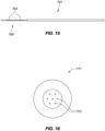
- FIG. 16 illustrates a cross-sectional view of one embodiment of a multi-core fiber 711.
- the multi-core fiber 711 can comprise a plurality of fiber cores 713.
- the multi-core fiber 711 can comprise seven separate fiber cores.
- the multi-core fiber can comprise two cores, three cores, four cores, five cores, six cores, eight cores, nine cores, or more as would be desired by one of ordinary skill in the art for various uses and medical procedures.
- FIG. 17 depicts an embodiment of a force body 751.
- the force body 751 can comprise a force body slot 753, a force body distal end 757, a force body proximal end 755, and a support tube 759.
- the force body 751 is depicted under a force imparted on the force body distal end 757.
- the force body slot 753 allows the force body 751 to bend in reaction to an applied force.
- a force body sealant within the force body slot can conform to the slot when it is compressed or stretched.
- the support tube 759 is coupled to the force body 751, the movement of the force body 751 is transferred to the support tube 759.
- FIG. 18 depicts a graph of the maximum principal strain experienced by three of the fibers within a multi-core fiber as the multi-core fiber is rolled 360°.
- the graph depicts the strain to a first fiber core 771, a second fiber core 773, and a third fiber core 775.
- FIG. 19A depicts an isometric view of one embodiment of a flexing structure assembly 822.
- the flexing structure assembly 822 can comprise an exemplary multi-core fiber 824 implemented in a flexing structure 816.
- the flexing structure assembly 822 can be positioned proximate a distal portion of a catheter shaft.
- the flexing structure 816 accommodates distal flexing from which at least the force sensors may sense deflection due to force against a structure, such as cardiac tissue.
- one or more slots, depicted as slots 818, 812, allow the flexing structure 816 to bend due to a force in response to contact with the tissue.
- one or more fiber Bragg grating force sensors are within three respective cores 802, 804, 806 (as seen in FIGS. 3A-3C ), and within the flexing structure 816, the force sensors can identify deflection of the flexing structure 816 in response to varying degrees of contact with tissue.
- Such sensors based on fiber Bragg grating may be implemented as described herein, and/or as described in U.S. Patent No. 8,182,433 assigned to the assignee of the instant application.
- the force sensors associated with the force sensing cores 802, 804, 806 may utilize a different optical technology.
- FIG. 19B depicts a side view of the flexing structure 816 depicted in FIG. 19A .
- the flexing structure 816 can comprise a plurality of slots 818, 820 to accommodate bending of the flexing structure 816 in response to contact with a distal end of a catheter.
- FIG. 19C depicts a side view of another embodiment of a catheter tip assembly 840.
- the catheter tip assembly 840 can comprise a flexing structure 846, a catheter tip 852, a first slot 848, a second slot 850, and a multi-core fiber 830.
- the flexing structure 846 can be positioned relative to the catheter tip 852, such as an ablation and/or mapping tip.
- the catheter tip 852 can comprise a plurality of irrigation ports 854 to enable cooling fluid to be discharged from the catheter during a medical procedure.
- the flexing structure 846 can be located proximate the catheter tip 852. Further examples of multi-core fibers and flexing structures can be found in U.S. Patent Application No. 15/400,655, filed 06 January 2017 and published as US 2017-0196479 , titled, "MEDICAL DEVICE WITH MULTI-CORE FIBER FOR OPTICAL SENSING" and assigned to the assignee of the instant application.
- the above described embodiments can allow for greater axial movement of the catheter and of the tip assembly, will not be affected by moisture, and can have higher manufacturing yields due to not having to work with a super tight tolerance, during fiber placement and fiber manufacturing " cleave angle" as is needed in previous force sensing catheters. Further, the above mentioned embodiments, can reduce the number of fibers in the catheter, reduce the time to assemble the sensor, and still uses a deformable body but it does not need to have a fiber slot.
- An additional advantage of at least some of the embodiments described herein comprise the multi-core fiber being placed within the irrigation lumen. Irrigant within the irrigation lumen moves through the irrigation lumen and around an outer wall of the multi-core fiber.
- Irrigant moves from the irrigation lumen into the proximal cavity of the tip assembly before moving to an inner cavity of the tip electrode and exiting the tip electrode through the catheter tip.
- the multi-core fiber is surrounded by irrigant within the tip assembly.
- An embodiment of a medical device incorporating such principles includes a manipulatable catheter having a shaft that has distal and proximal portions relative to the manipulating mechanism(s). Within the shaft is a multi-core optical fiber, having a plurality of optical cores dedicated for shape sensing sensors, and a plurality of optical cores dedicated for force sensing sensors.
- At least one of the cores of the multi-core optical fiber is dedicated for temperature compensation, which is used to adjust sensed values obtained from the shape sensing sensors and/or the force sensing sensors.
- the shape sensing sensors are implemented using one or more fiber Bragg gratings, which reflect light in a perceivable manner when deflected.
- the force sensing sensors are implemented using one or more fiber Bragg gratings, which also reflect light in a perceivable manner when deflected.
- Other embodiments implement fiber Bragg grating technology for both the force sensing and shape sensing sensors, where in yet another embodiment the temperature sensing core also utilizes fiber Bragg grating technology.
- One embodiment involves utilizing the multi-core fiber to accommodate only force sensors for detecting distal portion contact with tissue, while in another embodiment the multi-core fiber is utilized to accommodate only shaft shape sensors.
- the shape and force sensing cores are staggered from one another such that every other core is devoted to shape sensors, and the other cores are devoted to force sensors.
- this staggered pattern is substantially symmetric, and in still another embodiment a core to accommodate one or more temperature sensors (e.g., fiber Bragg grating) is positioned substantially centrally in the fiber relative to the surrounding, symmetric force and shape sensing cores.
- a flexing structure is provide proximate the force sensors in respective cores of the multi-core fiber to enable the distal portion of the catheter, and thus the included fiber, to deflect. This deflection is perceivable by the fiber Bragg grating or other sensors to provide an indication of an amount of force impacting the distal portion of the catheter.
- proximal and distal may be used throughout the specification with reference to a clinician manipulating one end of an instrument used to treat a patient.
- proximal refers to the portion of the instrument closest to the clinician and the term “distal” refers to the portion located furthest from the clinician.
- surgical instruments may be used in many orientations and positions, and these terms are not intended to be limiting and absolute.
- joinder references e.g., attached, coupled, connected, and the like are to be construed broadly and may include intermediate members between a connection of elements and relative movement between elements. As such, joinder references do not necessarily infer that two elements are directly connected and in fixed relation to each other.
Description
- This application claims the benefit of
United States provisional application no. 62/682,517, filed 08 June 2018 United States provisional application no. 62/719,811, filed 20 August 2018 - This disclosure relates to medical devices, and particularly to interventional and/or surgical catheters and other elongate medical devices capable of being visualized within a body as well as providing responsive feedback concerning tissue contact with a distal portion of the medical device.
- Within a cardiac cycle, the human heart experiences electrical impulses traversing from the sinus node to the ventricles. Cardiac contraction is driven by a cycle of polarization and depolarization as electrical currents spread across the heart. In healthy hearts, the heart will experience an orderly progression of depolarization waves called sinus rhythm. In unhealthy hearts, such as those experiencing atrial arrhythmia, including for example, ectopic atrial tachycardia, atrial fibrillation, and atrial flutter, the progression of the depolarization wave becomes chaotic. Arrhythmias may persist as a result of scar tissue or other obstacles to rapid and uniform depolarization. These obstacles may cause depolarization waves to electrically circulate through some parts of the heart more than once. Atrial arrhythmia can create a variety of dangerous conditions, including irregular heart rates, loss of synchronous atrioventricular contractions, and blood flow stasis. All of these conditions have been associated with a variety of ailments, including death.
- Catheters are used in a variety of diagnostic and/or therapeutic medical procedures to diagnose and correct conditions such as atrial arrhythmia, including for example, ectopic atrial tachycardia, atrial fibrillation, and atrial flutter. Typically, in atrial fibrillation therapies, a catheter is manipulated through a patient's vasculature to the patient's heart carrying one or more electrodes which may be used for mapping, ablation, diagnosis, or other treatment. Where an ablation therapy is desired to alleviate symptoms of atrial fibrillation, the ablation catheter imparts ablative energy to cardiac tissue to create a lesion in the cardiac tissue. The lesioned tissue is less capable of conducting electrical signals, thereby disrupting undesirable electrical pathways and limiting or preventing stray electrical signals that lead to arrhythmias. The ablation catheter may utilize ablative energy including, for example, radio-frequency (RF), cryoablation, laser, chemical, and high-intensity focused ultrasound. Ablation therapies often require precise positioning of the ablation catheter, as well as precise pressure exertion for optimal ablative-energy transfer into the targeted myocardial tissue. Excess force between the ablation catheter tip and the targeted myocardial tissue may result in excessive ablation which may permanently damage the cardiac muscle and/or surrounding nerves. When contact force between the ablation catheter tip and the targeted myocardial tissue is below a target force, the efficacy of the ablation therapy may be reduced, or entirely negated.
- For example, catheters are known from
WO 2017/118949 A1 ,US 2017/209209 A1 ,US 2014/276759 A1 ,WO 2010/011820 A2 andUS 2008/071267 A1 . A catheter with flat beam deflection in tip is known fromEP 2 732 845 A1 . - A medical device with means to improve transmission of torque is known from
US 2010/0249601 A1 . - Ablation therapies are often delivered by making a number of individual ablations in a controlled fashion in order to form a lesion line. To improve conformity of the individual ablations along the lesion line, it is desirable to precisely control the position at which the individual ablations are conducted, the ablation period, and the contact force between the ablation catheter tip and the targeted tissue. All of these factors affect the conformity of the resulting lesion line. Catheter localization systems, in conjunction with mapping systems, have vastly improved a clinician's ability to precisely position the ablation catheter tip for an ablation and determine the efficacy of a treatment. Similarly, ablation controller circuitry has improved the consistency of individual ablation therapies. There are devices that attempt to measure the force exerted between myocardial tissue and the ablation catheter tip. Existing designs utilize ablation catheter tips with deformable bodies which deform in response to a force being exerted on the ablation catheter tip. Sensors (e.g., magnetic, optical, etc.) are used to approximate the deformation of the deformable body and to output a signal to controller circuitry that associates the deformation with a force exerted by the ablation catheter tip. However, existing deformable body designs suffer from both complexity and cost, primarily related to acquisition and delivery of the measurement signal to the proximal end of the catheter.
- The foregoing discussion is intended only to illustrate the present field and should not be taken as a disavowal of claim scope.
- The present disclosure relates to medical devices, and particularly to interventional and/or surgical catheters and other elongate medical devices capable of being visualized within a body as well as providing responsive feedback concerning tissue contact with a distal portion of the medical device.
- In one embodiment, a tip assembly comprises a tip electrode and a coupler comprising at least one fiber support tube center. A distal portion of the coupler is coupled to a proximal portion of the tip electrode. The tip assembly further comprises a multi-core fiber comprising a plurality of cores and a fiber support tube. A proximal portion of the fiber support tube is coupled to and disposed within a through hole of the at least one fiber support tube center. The at least one fiber support tube center positions and keeps the multi-core fiber in the center of the coupler. The at least one fiber support tube center is coupled to an interior of the coupler outer wall.
- The foregoing and other aspects, features, details, utilities, and advantages of the present disclosure will be apparent from reading the following description and claims, and from reviewing the accompanying drawings.
-
-
FIG. 1 is a diagrammatic view of a system that can be used to perform an interventional medical procedure. -
FIG. 2 is a diagrammatic view of one embodiment of a force sensing system. -
FIGS. 3A and 3B are an isometric views of another embodiment of a multi-core fiber. -
FIG. 3C is an end view of the multi-core fiber ofFIGS. 3A and 3B . -
FIG. 4 is an isometric view of one embodiment of a tip assembly comprising a multi-core fiber. -
FIG. 5 is an isometric cross-sectional view of the tip assembly ofFIG. 4 . -
FIG. 6 is an isometric cross-sectional view of the tip assembly ofFIGS. 4 and5 . -
FIG. 7 is an isometric cross-sectional view of one embodiment of a tip assembly. -
FIG. 8 is an isometric view of one embodiment of a force body, a fluid cap, and a multi-core fiber. -
FIG. 9 is an isometric view of the force body and the multi-core fiber ofFIG. 8 . -
FIG. 10 is an isometric view of some components of an embodiment of a force body. -
FIG. 11 is an isometric view of some components of the force body ofFIG. 10 . -
FIG. 12 is an isometric view of some components of the force body ofFIGS. 10 and11 . -
FIG. 13 is an isometric view of one embodiment of a fluid cap. -
FIG. 14 is an isometric, blow out view of one embodiment of a tip assembly comprising a multi-core fiber. -
FIG. 15 is a side view of one embodiment of a multi-core fiber. -
FIG. 16 is a cross-sectional view of one embodiment of a multi-core fiber. -
FIG. 17 is a cross-sectional view of an embodiment of a force body and a multi-core fiber. -
FIG. 18 is a graph of the strain of three fibers within a multi-core fiber. -
FIG. 19A is an isometric view of one embodiment a flexing structure comprising a multi-core fiber. -
FIG. 19B is a side view of the embodiment of a flexing structure illustrated inFIG. 19A . -
FIG. 19C is a side view of one embodiment of a tip assembly comprising a flexing structure. - In the following description, reference is made to the accompanying drawings that depict representative examples. It is to be understood that other embodiments and implementations may be utilized. Like reference numbers are used throughout the disclosure where appropriate.
- The disclosure is generally directed to medical devices. Devices and techniques are disclosed relating to interventional and/or surgical catheters, introducers, and other elongate medical devices capable of being visualized within a body, as well as being capable of providing responsive feedback concerning tissue contact with a distal portion of the medical device.
- In one embodiment, a catheter or other elongate medical device is equipped with distal force sensing capabilities and elongate body shape sensing capabilities. In one embodiment, the distal force sensing and elongate body shape sensing capabilities are implemented with optical sensing technology. Such optical sensing technologies may involve different optical sensing technologies, such as, for example, fiber Bragg grating (FBG) shape sensing and optical interferometer distal force sensing. However, embodiments described herein using optical conduits (e.g., optical fibers, fiber cores, etc.) may utilize any optical technologies that transmit light via such optical conduits for use in the force and shape sensing mechanisms, whether the implemented force and shape sensing technologies are the same or dissimilar.
- Representative embodiments described herein also involve implementing a multi-core fiber(s) to provide the optical conduits through some or all of the catheter or other elongate body.
-
FIG. 1 illustrates arepresentative system 10 that may be used in an interventional medical procedure on abody 14. While the description herein may be described in terms of a particular representative medical procedure and/orbody 14 organ(s), it should be recognized that the principals described herein are equally applicable to other procedures and body organs. For example, while portions of the description may be described in terms of cardiac procedures and/or in terms of endocardial procedures involving the human heart, the principals described herein are equally applicable to other interventional procedures, such as epicardial procedures, renal denervation or other procedures involving the kidneys, vascular procedures, and the like. - Referring to
FIG. 1 , thesystem 10 includes a medical device, such as acatheter 19, introducer, or other interventional or surgical device where at least a portion of the device is placed within thebody 14. Therepresentative catheter 19 includes acatheter electrode assembly 11 shown within the cardiac space within thebody 14, where theelectrode assembly 11 is included as part of thecatheter 19 or other medical device and may be used, for example, for diagnosis, visualization, and/or treatment of tissue 13 (such as cardiac or other tissue) in thebody 14. For example, theelectrode assembly 11 may be used for ablation therapy oftissue 13 and/or mapping purposes in a patient'sbody 14. -
FIG. 1 further shows various representative sub-systems included in theoverall system 10. Thesystem 10 may include amain computing system 15, which may include a processing system, depicted inFIG. 1 as an electronic control unit (E.C.U.) 16 which represents any individual or distributed processing unit. Thecomputing system 15 may also includedata storage 17, e.g., memory and/or other storage. Thecomputer system 15 may further include conventional interface components, such as various user input/output mechanisms 18a and a display(s) 18b, among other components. Information obtained and/or provided by theelectrode assembly 11 may be processed by thecomputer system 15, and may provide data to the clinician via the input/output mechanisms 18a and/or thedisplay 18b, or in other ways as described herein or known in the art. - In the illustrative embodiment, the
catheter 19 may include one or more cable connectors orother interface 20, ahandle 21, an elongate (e.g., tubular) body orshaft 22 having aproximal portion 23 and adistal portion 24. Thedistal portion 24 does not represent any particular length, but rather distinguishes some usable portion of theshaft 22 within thebody 14 from a remainder of theshaft 22 that ultimately couples to thehandle 21 or other control mechanism (e.g., robotic controller). Thecatheter 19 may also include other conventional components not illustrated herein such as a temperature sensor(s), additional electrodes, corresponding conductors or leads, etc. Theconnector 20 may provide mechanical, fluid, optical and/or electrical connections for cables, such ascables fluid reservoir 12 andfluid pump 27, and thecomputer system 15. Theconnector 20 may comprise conventional components known in the art and, as shown in the illustrated embodiment, may be disposed at the proximal end of thecatheter 19. - In the case of a manually controlled catheter, a
handle 21 provides a portion for a user to grasp or hold thecatheter 19, and may further provide a mechanism for steering or guiding theshaft 22 within the patient'sbody 14. For example, thehandle 21 may include a mechanism configured to change the tension on a pull-wire(s) extending through thecatheter 19 to thedistal portion 24 of theshaft 22, or may include some other mechanism to steer theshaft 22. Thehandle 21 may be conventional in the art, and it will be understood that the configuration of thehandle 21 may vary. In an embodiment, thehandle 21 may be configured to provide visual, auditory, tactile and/or other feedback to a user based on information received from theelectrode assembly 11 or elsewhere along theshaft 22. For example, if contact totissue 13 is made by theelectrode assembly 11, any one or more of thehandle 21,computing system 15, I/O 18a and/ordisplay 18b may include graphical output, light-emitting-diodes or other visual indicators, tone generator, a vibrating mechanical transducer, and/or other indicator(s), the outputs of which could vary in proportion to the signal sensed at the electrode assembly. - The
system 10 ofFIG. 1 is merely an exemplary system described to provide a representative context in which the principals described herein may be utilized. Catheter-based diagnostic and treatment systems have been widely used for exploration and treatment of various organs or vessels. Such catheters are typically introduced through a vessel leading to the cavity of the organ to be explored or treated, or alternatively may be introduced in other ways such as directly through an incision made in the wall of the organ. This treatment avoids the trauma and extended recuperation times typically associated with open surgical procedures. For purposes of illustration, descriptions below may be described in representative context of a cardiac ablation procedure using an ablation catheter. - In order to provide effective diagnosis or therapy, the areas to be treated may first be mapped. Such mapping may be performed, for example, when it is desired to selectively ablate current pathways within the heart to treat atrial fibrillation or other electrical cardiac conduction issues. Often, the mapping procedure is complicated by difficulties in locating the zone(s) to be treated due to periodic movement of the heart throughout the cardiac cycle. Current systems rely on manual feedback of the catheter and/or impedance measurements to determine when the catheter is properly positioned in the vessel or organ. Better procedure efficacy may be obtained by measuring contact forces with the vessel or organ wall or detecting contact forces applied by the catheter against the organ or vessel wall that may modify the true wall location. For radio frequency (RF) ablation treatment, sustained contact force is beneficial as less contact force may result in poor ablation, and too much force can result in safety issues such as perforating the organ. Thus, it is desirable to provide apparatuses for detecting and monitoring contact forces between a catheter and the wall of the organ or vessel to permit faster and more accurate diagnostic and treatment.
- Force sensing technology can be very difficult to build. This difficulty can lead to poor yields in manufacturing. In Fabry-Perot sensors, the low manufacturing yields can be caused by the low cleave angle required to allow for a usable signal strength. The design of the force sensors can also be limited by the axial displacement of the sensor. The amount of axial displacement detected by the system is not only very difficult to work with on the measurements, it can also be very temperature dependent. Further, current force sensor technology can be susceptible to humidity, IE fluid ingress. For example, with Fabry-Perot sensors, fluid ingress can cause microbubbles to form in the fiber gap / at end of the fiber faces.
- As described in greater detail below, one such contact force technology involves optical sensors, such as sensors based on fiber Bragg grating. A fiber Bragg grating (FBG) is a desirable sensor for measuring the force for numerous reasons, such as it does not interfere with electronics and is compact in size. The FBG is a type of distributed Bragg reflector constructed in a segment of optical fiber that reflects particular wavelengths of light and transmits all others. This is achieved by creating a periodic variation in the refractive index of the fiber core thorough two light beams interfering. All wavelength lights have weak reflections at refractive index fringes, but only those wavelengths with phase matching condition will reflect back due to resonance effect and all other wavelength will transmit through the fiber.
- For a grating with a period of A and fiber core effective index neff, the Bragg wavelength λB is determined by the resonance condition as

- When a strain is applied to the fiber grating or ambient temperature changes, both the grating period and the fiber effective index will change accordingly, and hence the Bragg wavelength will shift to blue or red wavelength sides. By measuring the shift of the Bragg wavelength, the FBGs can be used for force and temperature sensing. One advantage derives from the absolute nature of the information-encoding in measuring the wavelength shift, which renders the sensor independent from fluctuating light power or connector losses. With an applied strain ε and the ambient temperature change dT, the shift of the Bragg wavelength is obtained by differential Eq. (1) as

where


- The Yong's modules E is defined as


Submit Eq. (4) into Eq. (2), the shift of Bragg wavelength with respect to the applied force and temperature change is expressed as
- To sense three-dimensional (3D) vector force and temperature, four independent sensors may be used in one embodiment. Four single FBGs can be used for the sensing, but ample space may be needed to mount the four FBGs. Additionally, all four FBGs may also involve separate calibration due to mechanical assembly, which limits the FBGs for sensing applications, especially in catheter applications as the size of the catheter tip may be only a few millimeters. The present disclosure describes a multi-core fiber comprising multiple core fibers that run the length of the fiber. The multi-core fiber can assist in limiting the cross-sectional space required within a catheter body for a plurality of independent channels as described herein.
- In accordance with one embodiment, when an FBG is inscribed on a multi-core fiber (MCFBG), e.g. at least four core fibers, four FBGs on four fiber cores can act as four sensors, but the overall size still corresponds to that of the single mode fiber. There can be no separate calibration issue, as all four FBGs are in the same fiber. If all cores are constructed substantially the same, the temperature change will correspondingly shift all four Bragg wavelengths, while only the force in the fiber axis direction will shift four Bragg wavelengths in the same mount. When force is applied to the MCFBGs with an angle, the fiber will be bent, and thus four FBGs will experience different compression and tension respectively while the Bragg wavelengths will shift to either short or long wavelengths depending on the force amplitude and its direction. In one embodiment, the end surface of MCFBGs is melted or otherwise amalgamated (e.g., into a ball) to minimize the reflection.
- In another embodiment, the catheter can comprise a multi-core fiber that has seven cores, the overall diameter of this fiber can be 155 microns or ~.006" each core is 6 microns. In one embodiment, all seven cores of the fiber can have gratings. In other embodiments, less than seven cores of the fiber can have gratings. Three of the outer cores can be monitored for force sensing and can be spaced at 120° from one another and the other three outer cores can be used for shape sensing. The last core in the center of the fiber can be used as temperature compensation / internal strain monitoring. If force is applied in a lateral direction one of the three cores can be put into a strech strain and two of the three cores can be put into compression strain. Further, if force is applied in an axial direction, all three cores can be placed into compression strain. In another embodiment, six of the outer cores can be monitored for force sensing and can be spaced at 60° from one another. In one embodiment, the center core can be used as temperature compensation / internal strain monitoring while the six outer cores are used for force sensing. In yet another embodiment, six cores can be used for monitoring a force imparted on a distal portion of the mulit-core fiber while all or a subset of the cores can have additional sensors proximal of the force sensing portion for determining or sensing a shape of the multi-core fiber. In this embodiment, a core can be used for both shape sensing and force sensing. Various configurations could be used. In some configurations all of the cores could be used for both shape sensing and force sensing. In other configurataions, a subsent of the cores could be used for both shape sensing and force sensing. In yet other configurations, the cores used for shape sensing can comprise shape sensing triplets or other sensors at different longitudinal areas of the core.
- As seen above, since Eq. (7) is a linear equation, the force and the temperature change will linearly shift all four FBG wavelengths and the force and temperature are then expressed as


where F 1, F 2 and F 3 are the three components of the force, θ and γ are the direction angles of the force, respectively. When a computer controlled optical switch makes a scan fromchannel 1 to 4 acquiring the Bragg wavelength shifts, the applied force and temperature change are achieved from Eq. (9). In another embodiment, a computer controlled optical switch makes a scan fromchannel 1 to 7 acquiring the Bragg wavelength shifts, the applied force and temperature change are achieved from Eq. (9). -
FIG. 2 is a diagram of a representative force sensing system utilizing a wavelength sweptfiber laser source 100, anoptical switch 102, a3D waveguide 104, acomputer 110, aphoto detector 108, a circulator 112, and a multi-core fiber Bragg gratings 106. In one embodiment, the 3D waveguide can comprise a fiber fan-out. Further, in one embodiment, thecomputer 110 can comprise a microprocessor. The computer can control the wavelength sweptfiber laser source 100 to emit an electromagnetic source or other signal. In the illustrated embodiment, the wavelength sweptfiber laser source 100 can transmit the source signal to the circulator 112. The source signal can then pass through theoptical switch 102, pass through the3D waveguide 104, and travel from a proximal end to a more distal portion of the multi-core fiber Bragg gratings 106. A portion of the signal can then be reflected and/or refracted towards the proximal end of the multi-corefiber Bragg gratings 106, through the circulator 112 and to thephoto detector 108. In one embodiment, thephoto detector 108 can send a signal to thecomputer 110. The computer can then process the signal to determine a degree of deflection enacted on a distal end of the multi-corefiber Bragg gratings 106 as described herein. In another embodiment, the signal returning from the multi-core fiber Bragg gratings can be directed to a sensor coupled to or part of the computer. While the multi-core fiber Bragg gratings is illustrated separately in the illustrated embodiment, the multi-core fiber Bragg gratings can be placed within a medical device or other object as described throughout this application. In one embodiment, the multi-core fiber can comprise a spun multi-core fiber. In a spun multi-core fiber, the cores of the multi-core fiber can twist throughout a length of the fiber. In some embodiments, a coordinate frame of the multi-core fiber can be synchronized with another two dimensional or three dimensional coordinate frame. Synchronizing the coordinate frames can allow for information acquired in the multi-core fiber coordinate frame to be overlaid on additional coordinate frames. - Representative embodiments and variations using techniques described herein are now described for purposes of example and illustration. An embodiment of a medical catheter with a force-sensing capability may provide, for example, a distal diagnostic or therapeutic tip region which is to be juxtaposed against tissue with a force, an intermediate and more proximal extended flexible lumen, a most proximal control handle with which to manipulate the catheter lumen and tip region within a patient's body lumens or organs, a force sensor to sense one or both of a tip bending force and a tip axial force as the distal tip is contacted to a patient's tissue (e.g., cardiac tissue). In such an embodiment, the force sensor may comprise a combination of a force-displacement calibrated spring and two or more optical displacement sensors capable of reporting one or more deflections of the spring as force is applied to the tip, where the optical displacement sensors comprise two or more Bragg gratings written upon two or more cores of a multi-core optical fiber, and where the detected spring deflections permit the tip force to be computed and reported since the spring is calibrated for force versus deflection and deflection is known.
- In further variations and alternatives, the optical displacement Bragg sensors may utilize wavelength scanning to determine displacement, where the wavelength scanning takes place in, for example, a console into which the catheter is connected, or in the handle of the catheter. Another option is for the multi-core fiber to have at least two cores peripheral to the fiber outer diameter, where in a more particular example the multiple cores are angularly distributed about the fiber's central axis in an approximately equally spaced manner. Another option is for the multi-core optical fiber to be optically connected to separate fibers using a 3D optical waveguides, which may further involve mounting an optical connector in or on the supporting or control console into which the catheter is plugged. In another embodiment, the calibrated spring includes a tubular multi-core fiber-encapsulating member whose spring stiffness includes the enclosed fiber. In another embodiment, the calibrated spring includes a separate spring which operates mechanically in parallel to any spring action provided by the fiber or its containment means, the overall net spring being the simultaneous combination of both springs in parallel. In yet another embodiment, the calibrated spring is separate from the fiber or its immediate encapsulation member, and the spring provides all of the calibrated spring action employed in force computation. Still another variation involves pre-stretching the fiber in tension or precompressing the fiber in compression during manufacture whether or not the fiber is itself encapsulated. Another variation includes a temperature measurement sensor to correct a Bragg grating detected displacement for thermal expansion, where in an even more particular embodiment the temperature sensor is any one of i) a thermocouple, ii) a thermistor, iii) a Bragg grating whose thermal expansion can be deduced optically and thereby acts as a temperature sensor. Yet another variation of such a medical device positions two or more such Bragg gratings on two or more cores of the fiber, where the gratings have the same axial fiber positions. Alternatively, two or more such Bragg gratings are positioned on a single core of the fiber and have different axial fiber positions. In another example, two or more Bragg gratings on one or more cores may have substantially the same grating period, or may have different grating periods. In one embodiment of the catheter, a region of the multi-core fiber which contains one or more Bragg gratings retains the fiber cladding, where in another embodiment the fiber cladding is stripped therefrom.
- In yet another example, the spring allows for at least one of a combined tip bending and tip axial compression, tip bending only, or axial compression only, where in a more specific embodiment the two or more Bragg optical displacement sensors detect at least a component of one or more of a bending force and an axial force. In yet another example, the net force or force component is reported as a vector. Representative variations of the catheter tip include the catheter tip being capable of ablating tissue using a tissue heating or cooling method, the catheter tip being capable of electrically pacing tissue, and the catheter tip being capable of electrically sensing tissue electrical waveforms. In one embodiment, the force information may be displayed on a screen in any numeric, icon or vector form; as an indication that a minimum recommended force has been or has not been attained or has or has-not been maintained, or is used in combination with the time of exposure to the therapy such that a numeric product or index of force and time or force/time integral can be reported. In other variations, the multi-core fiber is designed to prevent fiber buckling. In one embodiment, one or more optical displacement sensors are at least one of (a) immersed in flowed irrigant (e.g., saline) and in direct contact with the irrigant/fluid; (b) immersed in flowed irrigant but isolated from the irrigant by an overlying, encapsulating or encasing member or coating; (c) immersed in flowed irrigant but thermally insulated or buffered from the irrigant by an overlying encapsulating or encasing member or coating having a preselected thermal conductivity; (d) immersed in air, a gas or a vacuum; (e) immersed in a deformable gel; (f) mounted in a groove or channel; (g) cast or molded into a surrounding polymeric containing member. In yet another embodiment, the multi-core optical fiber is also employed with additional Bragg gratings arranged in the intermediate flexible lumen such that the flexing shape of the lumen itself can also be tracked in addition to the tip force. In another embodiment, the multi-core fiber is also employed to perform optical lesion feedback or optical tissue analysis. In some embodiments, the temperature can be measured or frequently updated by holding the catheter in the blood without applied force. Another option involves using a particular core's FBG (e.g., the center FBG) as a reference as bending will not shift the center FBG wavelength. FBGs on three-core or more can be used to measure the force and temperature in one embodiment, where alternatives include: (a) doping one or more of the cores (e.g., the center core) with a different material than other cores to optimize the parameters to separate the Bragg wavelength shifts of the applied force from the temperature to improve the force and temperature sensitivities; (b) making one or more of the cores a different diameter (e.g., the center core) to optimize the parameters to improve the force and temperature sensitivities; (c) where the cladding of the multi-core fiber is optionally designed with holes to optimize the parameters to improve the force and temperature sensitivities; and (d) where FBGs on multi-core crystal fibers are used as a sensor to improve the force and temperature sensitivities.
- In addition to providing force sensing functionality, other features may be included with such medical devices to provide further value for physicians during interventional or surgical medical procedures. For example, it would be beneficial to visually perceive relevant portions of the medical device that are otherwise veiled by the patient's body, such as a catheter shaft when introduced into the body and no longer directly visible. The present disclosure provides solutions to such challenges, by providing manners for tracking and mirroring the shape of some or all of the veiled portion of the medical device, such as some or all of the proximal portion and optionally some or substantially all of the distal portion of a catheter shaft during a medical procedure (e.g., during catheter-based diagnosis and/or treatment of tissue).
- In one embodiment, both optical force sensing and optical shape sensing are provided. One such manner of providing optical force and shape sensing is described in
U.S. Patent No. 8,622,935 . Optical conduits, such as optical fiber, may be used to transmit light to optical force sensors that detect forces impacting the catheter tip due to varying contact pressures between the catheter tip and body tissue. Other optical conduits may be used to transmit light along a desired length of the catheter shaft equipped with optical sensors, in order to enable the real-time position of the sensed portion of the catheter shaft to be positionally tracked and rendered for simulation of the catheter shaft within the body. - The optical sensors used for sensing the force against tissue and for sensing the changing shape of the catheter may utilize different optical sensing technologies, or a common optical sensing technology. For example, in one embodiment, optical fibers may be equipped with fiber Bragg gratings or other optical sensors to determine deflection of a distal portion of a catheter, which is representative of a magnitude and direction of a force bearing upon the catheter tip when contacting tissue during a medical procedure. In the same or other optical fibers, fiber Bragg gratings or other optical sensors may also be employed along a length of the catheter shaft that is tracked in real time as the catheter moves and consequently changes shape during the medical procedure.
- In embodiments further described below, the optical fibers used for both force sensing and shape sensing may be provided as multiple cores of a multi-core fiber. The multi-core fiber thus provides the light pathways and optical sensors for both force and shape sensing technologies.
- One embodiment of a multi-core fiber accommodating both sensors for force sensing and shape sensing is depicted in
FIG. 3A. FIG. 3A depicts an isometric view of amulti-core fiber 200. Themulti-core fiber 200 can comprise a plurality of separate cores. In the illustrated embodiment, themulti-core fiber 200 can comprise three cores to provide optical conduits for three respective force sensors (not shown). Themulti-core fiber 200 can comprise a firstoptical core 202, a secondoptical core 204, and a thirdoptical core 206. Themulti-core fiber 200 can further comprise a firstshape sensing core 208, a secondshape sensing core 210, and a thirdshape sensing core 212 to provide optical conduits for three respective shape sensing sensors (not shown). In the illustrated embodiment, a particular core located anywhere within the fiber, which in one embodiment is thecentral core 214, may be used to sense temperature changes by way of an optical sensor (e.g., FBG) at a distal core section. Sensing temperature with thecentral core 214 allows temperature compensation for the remaining off-axis cores 202-212. In other embodiments, four fibers can be used to derive a force component and a temperature. In one embodiment, a temperature peak and a normal peak can both be determined in the same gradient. In another embodiment, a temperature peak and a normal peak can both be determined in the same gradient and at the same magnitude.FIG. 3B depicts an isometric view of themulti-core fiber 200 ofFIG. 3A , while also illustrating an extension of the cores 202-214 through the body of themulti-core fiber 200. In one embodiment, a distal end of the multi-core fiber may be melted into a ball-like shape to minimize reflection.FIG. 3C depicts an end view of themulti-core fiber 200 illustrated inFIGS. 3A and 3B and depicts a representative arrangement of the multiple cores 202-212 offiber 200 from a perspective perpendicular to a longitudinal axis of thefiber 200. - In one embodiment, only shape sensing cores are implemented, such that only the first
shape sensing core 208, the secondshape sensing core 210, and the thirdshape sensing core 212, and optionally an additional core 214 (centrally located or not centrally located), are provided in themulti-core fiber 200. For example, the cores may be configured as shape sensing cores having a plurality of fiber Bragg gratings along the fiber, and therefore along the catheter shaft in which the fiber is enclosed. One or more temperature sensors may be included in one or more cores of the fiber. In such an embodiment, only shape sensing is performed utilizing the multi-core fiber, versus both shape sensing and force sensing. - In another embodiment, both shape sensing and force sensing are implemented using common cores, such that each core includes both shape sensing and force sensing sensors. For example, the frequency of light can be different in a common core for each of the force and shape sensing gratings respectively, which allows differentiation of the resulting reflections at the sensor signal processing unit.
-
FIG. 4 depicts an isometric view of one embodiment of atip assembly 301. The tip assembly 301can comprise aflex tip 309, aforce body 303, afluid cap 307, and anirrigation lumen 305. A multi-core fiber can be disposed within theirrigation lumen 305. In other embodiments, the multi-core fiber can be disposed exterior to the irrigation lumen. The tip assembly 301can comprise a multi-core fiber that can be disposed within theirrigation lumen 305. The tip assembly 301can accommodate distal flexing from which at least the force sensors may sense deflection due to force against a structure, such as cardiac tissue. In this embodiment, one ormore slots 317 allow theforce body 303 to bend due to a force in response to contact with the tissue. For example, where one or more fiber Bragg grating force sensors are within three respective cores and within theforce body 303, the force sensors can identify deflection of theforce body 303 in response to varying degrees of contact with tissue. In some embodiments, the force body can comprise a coupler. Such sensors based on fiber Bragg grating may be implemented as described herein, and/or as described inU.S. Patent No. 8,182,433 assigned to the assignee of the instant application. In other embodiments, the force sensors associated with the force sensing cores may utilize a different optical technology. Thefluid cap 307 can further comprise ashaft electrode groove 319, a firstelectrical channel 321, a secondelectrical channel 323, and acentral channel 325. Theshaft electrode groove 319 can comprise an annular space within an outer wall of thefluid cap 307 configured to allow an electrical wire to pass through theshaft electrode groove 319 to an electrode disposed distal of thefluid cap 307. The firstelectrical channel 321 and the secondelectrical channel 323 can comprise gaps disposed adjacent thecentral channel 325. The firstelectrical channel 321 and the secondelectrical channel 323 can be configured to allow for the passage of electrical wires, thermal sensors, anchor wires, and other materials as would be known to one of ordinary skill in the art from a position proximal of thetip assembly 301 to an inner portion of thetip assembly 301. -
FIG. 5 depicts an isometric cross-sectional view of the embodiment of the tip assembly 301seen inFIG. 4 . Thetip assembly 301 can comprise aflex tip 309, aforce body 303, afluid cap 307, anirrigation lumen 305, and amulti-core fiber 355. Theflex tip 309 can be coupled to a distal end of theforce body 303. Theflex tip 309 can comprise an electrode for sensing or ablating. Theflex tip 309 can further be configured to deliver energy. Theflex tip 309 can comprise aspring 337, aflex tip wall 331, and aflex tip cap 333. Thespring 337 can be disposed within an interior portion of theflex tip 309 and can be surrounded by theflex tip wall 331. Theflex tip cap 333 can comprise a plurality of irrigation throughholes 335 and can be coupled to a distal end of theflex tip wall 331. The plurality of irrigation throughholes 335 can be configured to allow for an irrigant that is distributed to an inner portion of theflex tip 309 to pass therethrough to an exterior portion of theflex tip 309. In other embodiments, the tip assembly can comprise a tip electrode. The tip electrode can comprise a flex tip electrode as described herein, or other tip electrodes as would be known to one of ordinary skill in the art. The tip electrode can be configured for sensing or ablating tissue. Theforce body 303 can comprise a force bodyouter wall 341, at least oneforce body slot 317, anirrigation balancing plate 351, a first fibersupport tube center 343, and a second fibersupport tube center 345. Theirrigation balancing plate 351 can be coupled to a distal end of the force bodyouter wall 341. In the illustrated embodiment, theirrigation balancing plate 351 and the distal portion of the force bodyouter wall 341 can be disposed within a proximal portion of theflex tip 309. In the illustrated embodiment, the distal portion of theforce body 303 can be disposed within an interior portion of theflex tip 309 and surrounded circumferentially by theflex tip wall 331. The at least oneforce body slot 317 can be a helical slot in the force bodyouter wall 341. Theforce body slot 317 can be configured to allow for theforce body 303 to flex when force is applied to theforce body 303. In the illustrated embodiment, theforce body slot 317 can comprise a slot through an entirety of the force bodyouter wall 341. In other embodiments, theforce body slot 317 can comprise a cut or other removal of material through all or part of the force body to allow the force body to bend when pressure is applied to the force body. Theforce body slot 317 can be filled with a flexible material that conforms to theforce body 303. In one embodiment, the flexible material can comprise a water tight seal. The first fibersupport tube center 343 and the second fibersupport tube center 345 can be coupled to an interior surface of the force bodyouter wall 341. The first fibersupport tube center 343 and the second fibersupport tube center 345 can coupled to themulti-core fiber 355 and can secure themulti-core fiber 355 within theforce body 303. In other embodiments, the force body can further comprise at least one thermocouple. The at least one thermocouple can be disposed within an interior portion of the force body. In one embodiment, the at least one thermocouple can be disposed within an irrigant pool within the force body. The at least one thermocouple be used to determine a temperature of irrigant within the force body. Further, the temperature of the irrigant can be used to determine a temperature of the multi-core fiber within the force body. - The
multi-core fiber 355 can comprise afiber support tube 347 and asupport tube slot 349. Thesupport tube slot 349 can comprise a helical slot in thefiber support tube 347. Thesupport tube slot 349 can be configured to allow for thefiber support tube 347 to flex when force is applied to theforce body 303. In the illustrated embodiment, thesupport tube slot 349 can comprise a slot through an entirety of thefiber support tube 347. In other embodiments, thesupport tube slot 349 can comprise a cut or other removal of material through all or part of thefiber support tube 347 to allow theforce body 303 to bend and/or compress when pressure is applied to theforce body 303. Thesupport tube slot 349 can be filled with a flexible material that conforms to thefiber support tube 347. In one embodiment, the flexible material can comprise a water tight seal. Theirrigation lumen 305 can comprise a lumen to deliver irrigation to thetip assembly 301. Themulti-core fiber 355 can be disposed within an interior portion of theirrigation lumen 305. In one embodiment, a distal end of theirrigation lumen 305 can be coupled to a central channel of thefluid cap 307. - The
fluid cap 307 can comprise a firstelectrical channel 321 and a secondelectrical channel 323. Thefluid cap 307 can be coupled to a proximal end of theforce body 303. The firstelectrical channel 321 and the secondelectrical channel 323 can comprise channels through thefluid cap 307. Electrical wires, support wires, anchoring members and other devices can be passed through the firstelectrical channel 321 and the secondelectrical channel 323 to allow various components access to an interior portion of thetip assembly 301. -
FIG. 6 illustrates an isometric cross-sectional view of the embodiment of thetip assembly 301 seen inFIGS. 4 and5 . Thetip assembly 301 can comprise aflex tip 309, aforce body 303, afluid cap 307, and amulti-core fiber 355. The irrigation lumen as seen inFIG. 5 has been omitted from the drawing to allow for a better view of themulti-core fiber 355 passing through thefluid cap 307. As seen in the illustrated embodiment, themulti-core fiber 355 can pass through a center of thecentral channel 325 of thefluid cap 307. Themulti-core fiber 355 can follow a center-line of theforce body 303. Themulti-core fiber 355 can be positioned and kept in the center of theforce body 303 through the first fibersupport tube center 343 and the second fibersupport tube center 345. -
FIG. 7 depicts an isometric cross-sectional view of another embodiment of atip assembly 357. Thetip assembly 357 can comprise aflex tip 361, acoupler 359, and amulti-core fiber 383. Theflex tip 361 can be coupled to a distal end of thecoupler 359. Theflex tip 361 can comprise an electrode for sensing or ablating. Theflex tip 361 can further be configured to deliver energy. Theflex tip 361 can comprise aspring 369, aflex tip wall 373, and aflex tip cap 363. Thespring 369 can be disposed within an interior portion of theflex tip 361 and can be surrounded by theflex tip wall 373. Theflex tip cap 363 can comprise a plurality of irrigation throughholes 365 and a second fibersupport tube center 367. Theflex tip cap 363 can be coupled to a distal end of theflex tip wall 373. The plurality of irrigation throughholes 365 can be configured to allow for an irrigant that is distributed to an inner portion of theflex tip 361 to pass therethrough to an exterior portion of theflex tip 361. In the illustrate embodiment (not being part of the claimed invention), the second fibersupport tube center 367 can be integral with theflex tip cap 363. The second fibersupport tube center 367 can comprise aninner wall 371. The inner wall can be sized and configured to receive a distal end of a fiber support tube. In other embodiments, the second fibersupport tube center 367 can be configured to receive a distal portion a fiber support tube. The second fibersupport tube center 367 can be configured to secure the distal end of the fiber support tube to theflex tip cap 363. Through securing the distal end of the fiber support tube, the multi-core fiber can bend as described throughout this application. In other embodiments, the tip assembly can comprise a tip electrode. The tip electrode can comprise a flex tip electrode as described herein, or other tip electrodes as would be known to one of ordinary skill in the art. The tip electrode can be configured for sensing or ablating tissue. Thecoupler 359 can comprise a couplerouter wall 389, a couplerproximal end 381, and a first fibersupport tube center 377. In some embodiments, the coupler can comprise a force body. In the illustrated embodiment, the distal portion of thecoupler 359 can be disposed within an interior portion of theflex tip 361 and surrounded circumferentially by theflex tip wall 373. The first fibersupport tube center 377 can be coupled to an interior surface of the couplerouter wall 389. The first fibersupport tube center 377 and the second fibersupport tube center 367 can coupled to themulti-core fiber 383 and can secure themulti-core fiber 383 within thetip assembly 357. In other embodiments, the coupler can further comprise at least one thermocouple. The at least one thermocouple can be disposed within an interior portion of the coupler or within the flex tip. In one embodiment, the at least one thermocouple can be disposed within an irrigant pool within the coupler. The at least one thermocouple be used to determine a temperature of irrigant within the coupler. Further, the temperature of the irrigant can be used to determine a temperature of the multi-core fiber within the coupler. - The
multi-core fiber 383 can comprise afiber support tube 375 and asupport tube slot 391. As stated in the rest of the application, the multi-core fiber can comprise a plurality of cores. Each of these cores can be used for one or more of force sensing, shape sensing, or temperature compensation. In various embodiments, each of the cores can be configured to use the force sensing, shape sensing, or temperature compensation at the same time or separately. In the illustrated embodiment, thefiber support tube 375 can be disposed within an interior portion of theflex tip 361. In the illustrated embodiment, a distal portion of thefiber support tube 375 can be coupled to the second fibersupport tube center 367. The second fibersupport tube center 367 can be integral with the flex tip cap 363 (not being part of the claimed invention). A proximal portion of thefiber support tube 375 can be coupled to the first fibersupport tube center 377. In the illustrated embodiment the first fibersupport tube center 377 can be disposed within the coupler and the second fibersupport tube center 367 can be integral with the flex tip cap 363 (not being part of the claimed invention). Thefiber support tube 375 can be disposed within an interior portion of thecoupler 359, theflex tip wall 373, and theflex tip cap 363. Thesupport tube slot 391 can comprise a helical slot in thefiber support tube 375. Thesupport tube slot 391 can be configured to allow for thefiber support tube 375 to flex when force is applied to thetip assembly 357. In the illustrated embodiment, thesupport tube slot 391 can comprise a slot through an entirety of thefiber support tube 375. In other embodiments, thesupport tube slot 391 can comprise a cut or other removal of material through all or part of thefiber support tube 375 to allow thetip assembly 357 to bend and/or compress when pressure is applied to thetip assembly 357. Thesupport tube slot 391 can be filled with a flexible material that conforms to thefiber support tube 375. In one embodiment, the flexible material can comprise a water tight seal. - The coupler
proximal end 381 can comprise a firstelectrical channel 379 and a secondelectrical channel 387. The couplerproximal end 381 can be coupled and/or integral to a proximal end of thecoupler 359. The firstelectrical channel 379 and the secondelectrical channel 387 can comprise channels through the couplerproximal end 381. Electrical wires, support wires, anchoring members and other devices can be passed through the firstelectrical channel 379 and the secondelectrical channel 387 to allow various components access to an interior portion of thetip assembly 357. -
FIG. 8 depicts an isometric view of an embodiment of aforce body 403, afluid cap 407, and amulti-core fiber 455. Theforce body 403 can comprise anirrigation balancing plate 451, adistal neck 433, at least one forcebody irrigation port 435, aforce body slot 417, and a force body shaftelectrode ring groove 431. Theirrigation balancing plate 451 can be coupled to a distal end of thedistal neck 433 of theforce body 403. The at least one forcebody irritation port 435 can be disposed on thedistal neck 433 of theforce body 403. The at least one forcebody irrigation port 435 can be configured to allow irrigant to pass from an inner portion of theforce body 403 to an exterior portion of theforce body 403. In the illustrated embodiment, the at least one forcebody irrigation port 435 can comprise a plurality of irrigation ports that can be evenly distributed around a circumference of thedistal neck 433. In other embodiments, the at least one force body irrigation port can comprise a plurality of irrigation ports that can be distributed in an uneven configuration. The uneven configuration can be configured to direct more irrigant to certain areas of the tip electrode. The increased irrigant can be used to cool certain portions of the tip electrode or to push additional irrigant to an area external of the tip electrode when compared to areas of the tip electrode without a force body irrigation port adjacent. The force body shaftelectrode ring groove 431 can comprise a depression within an exterior wall of theforce body 403. The force body shaftelectrode ring groove 431 can comprise a longitudinal groove or depression within theforce body 403. The force body shaftelectrode ring groove 431 can be disposed between a proximal end offorce body 403 and a more distal position. The force body shaftelectrode ring groove 431 can be configured to allow an electrical wire to be disposed therein. The force body shaftelectrode ring groove 431 can further be configured to allow for the electrical wire to terminate and/or couple to a ring electrode disposed adjacent to theforce body 403. Thefluid cap 407 can comprise acentral channel 425, a firstelectrical channel 421, a secondelectrical channel 423, and a cap shaftelectrode ring groove 419. The cap shaftelectrode ring groove 419 can comprise a depression within an exterior wall of thefluid cap 407. The cap shaftelectrode ring groove 419 can comprise a longitudinal groove or depression within thefluid cap 407. The cap shaftelectrode ring groove 419 can be disposed between a proximal end offluid cap 407 and a distal end of thefluid cap 407. The cap shaftelectrode ring groove 417 can be configured to allow an electrical wire to be disposed therein. -
FIG. 9 depicts an isometric view of the embodiment of theforce body 403 and themulti-core fiber 455 illustrated inFIG. 8 . In the illustrated embodiment, the fluid cap has been removed and is not shown. Theforce body 403 can comprise anirrigation balancing plate 451, adistal neck 433, at least one forcebody irrigation port 435, aforce body slot 417, and a force body shaftelectrode ring groove 431. -
FIG. 10 depicts an isometric view of some components of a force body.FIG. 10 depicts anirrigation balancing plate 551, a first fibersupport tube center 543, a second fibersupport tube center 545, asupport tube 547, asupport tube slot 549, aforce body sealant 561, and amulti-core fiber 555. Theirrigation balancing plate 551 can comprise at least one plate irrigation throughholes 563. The at least one plate irrigation throughholes 563 can be configured to allow an irrigant to pass from a proximal side of theirrigation balancing plate 551 to a distal side of theirrigation balancing plate 551. The first fibersupport tube center 543 can comprise a first center through-hole 565 and the second fibersupport tube center 545 can comprise a second center through-hole 567. Themulti-core fiber 555 can comprise asupport tube 547 and a support tube slot 59. Thesupport tube 547 can surround a distal portion of themulti-core fiber 555. Theforce body sealant 561 can comprise a sealant formed in a helical pattern that can fit within the force body slot described throughout this application. Theforce body sealant 561 can surround a distal portion of themulti-core fiber 555. A distal end of thesupport tube 547 can be coupled to and disposed within the second throughhole 567 of the second fibersupport tube center 545 and a proximal end of thesupport tube 547 can be coupled to and disposed within the first throughhole 565 of the first fibersupport tube center 543. - The first fiber
support tube center 543 and the second fibersupport tube center 545 can each further comprise at least one centeringprotrusion 571. Each of the ate least one centeringprotrusion 571 can extend outward in a radial direction from a center of the fiber support tube center. Each of the ate least one centeringprotrusion 571 can comprise a protrusionouter surface 573. The protrusionouter surface 573 can be shaped and configured to interact with an inner wall of a force body. The protrusion outer surface can interact with the inner wall of the force body to center the through-hole in the force body. In the illustrated embodiment, each of the fiber support tube centers can comprise four centering protrusions. In one embodiment, each of the centering protrusions can be spaced 90 degrees from each neighboring centering protrusion. In the illustrated embodiment, the centering protrusions are spaced to create a rectangular shape by their outer surface. In the illustrated embodiment, each of the fiber support tube centers further comprises a centeringdepression 575 between each of the at least one centeringprotrusion 571. Each fiber support tube center can comprise multiple centeringdepressions 575. In one embodiment, at least one of the centering depressions can be configured to allow for electrical wires or other components of a catheter to pass through the centering depression and proceed to a more distal location within the tip assembly. -
FIG. 11 depicts an isometric view of some of the components illustrated inFIG. 10 .FIG. 11 depicts anirrigation balancing plate 551, asupport tube 547, asupport tube slot 549, a thermocouple throughhole 559, and amulti-core fiber 555. In the illustrated embodiment, a longitudinal axis of themulti-core fiber 555 passes through a center portion of theirrigation balancing plate 551. Further, in the illustrated embodiment, the at least one plate irrigation throughholes 563 comprise a plurality of plate irrigation through holes. The plurality of plate irrigation through holes can be distributed evenly around a circumference of theirrigation balancing plate 551. In other embodiments, the plurality of plate irrigation through holes can comprise various distances between each other as would be desired to direct fluid into a catheter tip. In the illustrated embodiment, the plurality of plate irrigation through holes can be the same distance from a center point of the irrigation plate. In other embodiments, the plurality of plate irrigation through holes can vary in distance from a center point of the irrigation plate. The thermocouple throughhole 559 can be used to pass a thermocouple from proximal of theirrigation balancing plate 551 to a more distal portion of the tip assembly. In another embodiment, the thermocouple through hole can be used and/or configured to pass a thermal sensor from proximal of theirrigation balancing plate 551 to a more distal portion of the tip assembly. In other embodiments, theirrigation balancing plate 551 can comprise a plurality of thermocouple through holes. In yet another embodiment, the thermocouple through hole can be sized and configured to pass multiple thermocouples or other thermal sensors through the irrigation balancing plate. -
FIG. 12 depicts an isometric view of some of the components illustrated inFIGS. 10 and11. FIG. 12 depicts anirrigation balancing plate 551, amulti-core fiber 555, afiber sealant 569, a thermocouple throughhole 559, and at least one plate irrigation throughhole 563. Thefiber sealant 569 can surround a distal portion of themulti-core fiber 555. Thefiber sealant 569 can be formed in a helical shape surrounding themulti-core fiber 555. Thefiber sealant 569 can be configured to allow themulti-core fiber 555 and support tube to move when a lateral or vertical force is imparted to themulti-core fiber 555. -
FIG. 13 depicts an isometric view of an embodiment of afluid cap 601. Thefluid cap 601 can comprise a shaftelectrode ring groove 613, a firstelectrical channel 607, a secondelectrical channel 609, acenter channel 611, aproximal face 603, and adistal portion 605. The distal portion 65 of thefluid cap 601 can comprise a smaller diameter than a more proximal portion of thefluid cap 601. Thedistal portion 605 can be configured to couple to another component. In one embodiment, thedistal portion 605 can be configured to couple to a force body. Thecentral channel 611 can be configured to couple to an irrigation lumen. The firstelectrical channel 607 and the secondelectrical channel 609 can each comprise a cavity that extends from theproximal face 603 of thefluid cap 601 to a distal end of thefluid cap 601. Each of the firstelectrical channel 607 and the secondelectrical channel 609 can be configured to allow for electrical wires or other components of a catheter to pass through thefluid cap 601. -
FIG. 14 depicts an isometric blown out view of one embodiment of atip assembly 601. The tip assembly 601comprises aflex tip cap 633, aflex tip wall 631, aspring 637, anirrigation balancing plate 651, a second fibersupport tube center 645, asupport tube 647, asupport tube slot 649, asupport tube sealant 669, a first fibersupport tube center 643, aforce body 603, afluid cap 607, and amulti-core fiber 655. Theflex tip cap 633 can be configured to couple to a distal end of theflex tip wall 631. Thespring 637 can be disposed against an inner surface of theflex tip wall 631. Theirrigation balancing plate 651 can be coupled to a distal end of theforce body 603. Theirrigation balancing plate 651 can further be disposed within an interior portion of theflex tip wall 631. The second fibersupport tube center 645 can be coupled to an inner surface of theforce body 603 and can also be coupled to a distal end of thesupport tube 647. Thesupport tube slot 649 can comprise a helical void within thesupport tube 647 and thesupport tube sealant 669 can be disposed within thesupport tube slot 649. The first fibersupport tube center 643 can be coupled to an inner surface of theforce body 603 and can also be coupled to a proximal end of thesupport tube 647. A proximal portion of theforce body 603 can be coupled to theflex tip wall 631. Theforce body 603 can comprise a force body slot. The force body slot can comprise a helical void within an outer wall of theforce body 603. Theforce body sealant 661 can be disposed within the force body slot. Thefluid cap 607 can be coupled to a proximal end of theforce body 603. A distal portion of themulti-core fiber 655 can be disposed within thesupport tube 647. A portion of themulti-core fiber 655 proximal of the support tube can pass through a center channel of thefluid cap 607. -
FIG. 15 illustrates a side view of one embodiment of amulti-core fiber 701. Themulti-core fiber 701 can comprise adistal portion 705. As described above, thedistal portion 705 can comprise a plurality of Fiber Bragg gratings 703. The Fiber Bragg gratings can be used to determine force and for shape sensing as described throughout the application. -
FIG. 16 illustrates a cross-sectional view of one embodiment of amulti-core fiber 711. Themulti-core fiber 711 can comprise a plurality offiber cores 713. In the illustrated embodiment, themulti-core fiber 711 can comprise seven separate fiber cores. In various other embodiments, the multi-core fiber can comprise two cores, three cores, four cores, five cores, six cores, eight cores, nine cores, or more as would be desired by one of ordinary skill in the art for various uses and medical procedures. -
FIG. 17 depicts an embodiment of aforce body 751. Theforce body 751 can comprise aforce body slot 753, a force bodydistal end 757, a force bodyproximal end 755, and asupport tube 759. Theforce body 751 is depicted under a force imparted on the force bodydistal end 757. As seen in the illustrated embodiment, theforce body slot 753 allows theforce body 751 to bend in reaction to an applied force. While not shown, a force body sealant within the force body slot can conform to the slot when it is compressed or stretched. Further, as thesupport tube 759 is coupled to theforce body 751, the movement of theforce body 751 is transferred to thesupport tube 759. -
FIG. 18 depicts a graph of the maximum principal strain experienced by three of the fibers within a multi-core fiber as the multi-core fiber is rolled 360°. The graph depicts the strain to afirst fiber core 771, asecond fiber core 773, and athird fiber core 775. -
FIG. 19A depicts an isometric view of one embodiment of a flexingstructure assembly 822. The flexingstructure assembly 822 can comprise an exemplarymulti-core fiber 824 implemented in a flexingstructure 816. In one embodiment, the flexingstructure assembly 822 can be positioned proximate a distal portion of a catheter shaft. In the illustrated embodiment, the flexingstructure 816 accommodates distal flexing from which at least the force sensors may sense deflection due to force against a structure, such as cardiac tissue. In this embodiment, one or more slots, depicted asslots 818, 812, allow the flexingstructure 816 to bend due to a force in response to contact with the tissue. For example, where one or more fiber Bragg grating force sensors are within three respective cores 802, 804, 806 (as seen inFIGS. 3A-3C ), and within the flexingstructure 816, the force sensors can identify deflection of the flexingstructure 816 in response to varying degrees of contact with tissue. Such sensors based on fiber Bragg grating may be implemented as described herein, and/or as described inU.S. Patent No. 8,182,433 assigned to the assignee of the instant application. In other embodiments, the force sensors associated with the force sensing cores 802, 804, 806 (as seen inFIGS. 3A-3C ) may utilize a different optical technology. -
FIG. 19B depicts a side view of the flexingstructure 816 depicted inFIG. 19A . The flexingstructure 816 can comprise a plurality ofslots structure 816 in response to contact with a distal end of a catheter. -
FIG. 19C depicts a side view of another embodiment of acatheter tip assembly 840. Thecatheter tip assembly 840 can comprise a flexingstructure 846, acatheter tip 852, afirst slot 848, asecond slot 850, and amulti-core fiber 830. The flexingstructure 846 can be positioned relative to thecatheter tip 852, such as an ablation and/or mapping tip. Thecatheter tip 852 can comprise a plurality ofirrigation ports 854 to enable cooling fluid to be discharged from the catheter during a medical procedure. In one embodiment, the flexingstructure 846 can be located proximate thecatheter tip 852. Further examples of multi-core fibers and flexing structures can be found inU.S. Patent Application No. 15/400,655, filed 06 January 2017 US 2017-0196479 , titled, "MEDICAL DEVICE WITH MULTI-CORE FIBER FOR OPTICAL SENSING" and assigned to the assignee of the instant application. - The above described embodiments can allow for greater axial movement of the catheter and of the tip assembly, will not be affected by moisture, and can have higher manufacturing yields due to not having to work with a super tight tolerance, during fiber placement and fiber manufacturing " cleave angle" as is needed in previous force sensing catheters. Further, the above mentioned embodiments, can reduce the number of fibers in the catheter, reduce the time to assemble the sensor, and still uses a deformable body but it does not need to have a fiber slot. An additional advantage of at least some of the embodiments described herein comprise the multi-core fiber being placed within the irrigation lumen. Irrigant within the irrigation lumen moves through the irrigation lumen and around an outer wall of the multi-core fiber. Irrigant moves from the irrigation lumen into the proximal cavity of the tip assembly before moving to an inner cavity of the tip electrode and exiting the tip electrode through the catheter tip. As a result, the multi-core fiber is surrounded by irrigant within the tip assembly.
- An embodiment of a medical device incorporating such principles includes a manipulatable catheter having a shaft that has distal and proximal portions relative to the manipulating mechanism(s). Within the shaft is a multi-core optical fiber, having a plurality of optical cores dedicated for shape sensing sensors, and a plurality of optical cores dedicated for force sensing sensors.
- In a more particular embodiment, at least one of the cores of the multi-core optical fiber is dedicated for temperature compensation, which is used to adjust sensed values obtained from the shape sensing sensors and/or the force sensing sensors. In one embodiment, the shape sensing sensors are implemented using one or more fiber Bragg gratings, which reflect light in a perceivable manner when deflected. In another embodiment, the force sensing sensors are implemented using one or more fiber Bragg gratings, which also reflect light in a perceivable manner when deflected. Other embodiments implement fiber Bragg grating technology for both the force sensing and shape sensing sensors, where in yet another embodiment the temperature sensing core also utilizes fiber Bragg grating technology.
- One embodiment involves utilizing the multi-core fiber to accommodate only force sensors for detecting distal portion contact with tissue, while in another embodiment the multi-core fiber is utilized to accommodate only shaft shape sensors.
- In one embodiment where the multi-core fiber accommodates cores for both shape and force sensing, the shape and force sensing cores are staggered from one another such that every other core is devoted to shape sensors, and the other cores are devoted to force sensors. In one particular embodiment, this staggered pattern is substantially symmetric, and in still another embodiment a core to accommodate one or more temperature sensors (e.g., fiber Bragg grating) is positioned substantially centrally in the fiber relative to the surrounding, symmetric force and shape sensing cores.
- Any manner of enabling deflection of the shaft and catheter tip may be utilized. In one embodiment, a flexing structure is provide proximate the force sensors in respective cores of the multi-core fiber to enable the distal portion of the catheter, and thus the included fiber, to deflect. This deflection is perceivable by the fiber Bragg grating or other sensors to provide an indication of an amount of force impacting the distal portion of the catheter.
- Although the subject matter has been described in language specific to structural features and/or methodological acts, it is to be understood that the subject matter defined in the appended claims is not necessarily limited to the specific features or acts described above. Rather, the specific features and acts described above are disclosed as representative forms of implementing the claims.
- Further, although several embodiments have been described above with a certain degree of particularity to facilitate an understanding of at least some ways in which the disclosure may be practiced, those skilled in the art could make numerous alterations to the disclosed embodiments without departing from the scope of the present disclosure and the appended claims. It is intended that all matter contained in the above description or shown in the accompanying drawings shall be interpreted as illustrative only and not limiting. Accordingly, the examples and embodiments herein should not be construed as limiting the scope of the disclosure. Changes in detail or structure may be made without departing from the present teachings. The foregoing description and following claims are intended to cover all such modifications and variations.
- Various embodiments are described herein of various apparatuses and systems. Numerous specific details are set forth to provide a thorough understanding of the overall structure, function, manufacture, and use of the embodiments as described in the specification and illustrated in the accompanying drawings. It will be understood by those skilled in the art, however, that the embodiments may be practiced without such specific details. In other instances, well-known operations, components, and elements may not have been described in detail so as not to obscure the embodiments described in the specification. Those of ordinary skill in the art will understand that the embodiments described and illustrated herein are non-limiting examples, and thus it can be appreciated that the specific structural and functional details disclosed herein may be representative and do not necessarily limit the scope of the embodiments, the scope of which is defined solely by the appended claims.
- The terms "including," "comprising" and variations thereof, as used in this disclosure, mean "including, but not limited to," unless express specified otherwise. The terms "a," "an," and "the," as used in this disclosure, means "one or more," unless expressly specified otherwise.
- Reference throughout the specification to "various embodiments," "some embodiments," "one embodiment," "an embodiment," or the like, means that a particular feature, structure, or characteristic described in connection with the embodiment is included in at least one embodiment. Thus, appearances of the phrases "in various embodiments," "in some embodiments," "in one embodiment," "in an embodiment," or the like, in places throughout the specification are not necessarily all referring to the same embodiment. Furthermore, the particular features, structures, or characteristics may be combined in any suitable manner in one or more embodiments within the scope of the appended claims. Thus, the particular features, structures, or characteristics illustrated or described in connection with one embodiment may be combined, in whole or in part, with the features, structures, or characteristics of one or more other embodiments within the scope of the appended claims.
- Although process steps, method steps, algorithms, or the like, may be described in a sequential order, such processes, and algorithms may be configured to work in alternative orders. In other words, any sequence or order of steps that may be described does not necessarily indicate a requirement that the steps be performed in that order. The steps of the processes, methods, and algorithms described herein may be performed in any order practical. Further, some steps may be performed simultaneously.
- When a single device or article is described herein, it will be readily apparent that more than one device or article may be used in place of a single device or article. Similarly, where more than one device or article is described herein, it will be readily apparent that a single device or article may be used in place of the more than one device or article. The functionality or the features of a device may be alternatively embodied by one or more other devices which are not explicitly described as having such functionality or features.
- It will be appreciated that the terms "proximal" and "distal" may be used throughout the specification with reference to a clinician manipulating one end of an instrument used to treat a patient. The term "proximal" refers to the portion of the instrument closest to the clinician and the term "distal" refers to the portion located furthest from the clinician. However, surgical instruments may be used in many orientations and positions, and these terms are not intended to be limiting and absolute. All other directional or spatial references (e.g., upper, lower, upward, downward, left, right, leftward, rightward, top, bottom, above, below, vertical, horizontal, clockwise, and counterclockwise) are only used for identification purposes to aid the reader's understanding of the present disclosure, and do not create limitations, particularly as to the position, orientation, or use of the disclosure. Joinder references (e.g., attached, coupled, connected, and the like) are to be construed broadly and may include intermediate members between a connection of elements and relative movement between elements. As such, joinder references do not necessarily infer that two elements are directly connected and in fixed relation to each other.
- Based upon the above discussion and illustrations, those skilled in the art will readily recognize that various modifications and changes may be made to the various embodiments without strictly following the exemplary embodiments and applications illustrated and described herein within the scope of the appended claims.
Claims (15)
- A tip assembly (301, 357, 601), comprisinga tip electrode;a coupler (359) comprising at least one fiber support tube center (343, 377, 543, 643), wherein a distal portion of the coupler (359) is coupled to a proximal portion of the tip electrode; anda multi-core fiber (383, 455, 555, 655) comprising a plurality of cores (202, 204, 206, 208, 210, 212) and a fiber support tube (347, 375, 547, 647),wherein a proximal portion of the fiber support tube (347, 375, 547, 647) is coupled to and disposed within a through hole (565, 567) of the at least one fiber support tube center (343, 377, 543, 643),wherein the at least one fiber support tube center (343, 377, 543, 643) positions and keeps the multi-core fiber (383, 455, 555, 655) in the center of the coupler (359), andwherein the at least one fiber support tube center (343, 377, 543, 643) is coupled to an interior of a coupler outer wall (389).
- The tip assembly (301, 357, 601) according to claim 1, wherein the tip electrode comprises a flex electrode.
- The tip assembly (301, 357, 601) according to claim 1 or 2, wherein the coupler (359) further comprises an irrigation balancing plate (351, 451, 551, 651) coupled to a distal end of the coupler (359) and comprising at least one irrigation through hole (563).
- The tip assembly (301, 357, 601) according to claim 3, wherein the irrigation balancing plate (351, 451, 551, 651) comprises at least one plate irrigation through holes.
- The tip assembly (301, 357, 601) according to any one of claims 1 to 4, wherein the multi-core fiber (383, 465, 555, 655) comprises at least four core fibers.
- The tip assembly (301, 357, 601) according to any one of claims 1 to 5, further comprising a fluid cap (307, 407, 601) coupled to a proximal end of the coupler (359).
- The tip assembly (301, 357, 601) according to claim 6, wherein the fluid cap comprises a central channel (325, 425, 611) and wherein the multi-core fiber (383, 465, 555, 655) passes through the central channel (325, 425, 611).
- The tip assembly (301, 357, 601) according to claim 6, further comprising an irrigation lumen (305) coupled to the fluid cap (307, 407, 601).
- The tip assembly (301, 357, 601) according to claim 8, wherein the multi-core fiber (383, 455, 555, 655) is disposed within the irrigation lumen (305) and/or wherein multi-core fiber (383, 455, 555, 655) is disposed within an interior portion of the tip electrode.
- The tip assembly (301, 357, 601) according to any one of claims 1 to 9, wherein the at least one fiber support tube center (343, 377, 543, 643) is a first fiber support tube center; and the tip assembly (301, 357, 601) further comprises a flex tip comprising a second fiber support tube center (345, 367, 545, 645), whereinthe flex tip is coupled to a distal portion of the coupler (359), andthe fiber support tube (347, 375, 547, 647) is coupled to the first fiber support tube center (343, 377, 543, 643) and the second fiber support tube center (345, 367, 545, 645).
- The tip assembly (301, 357, 601) according to claim 10, wherein the first fiber support tube center (343, 377, 543, 643) comprises a plurality of centering protrusions (571), wherein the coupler (359) preferably further comprises an interior surface, wherein the each of the plurality of centering protrusions (571) comprises a protrusion outer surface, and wherein the protrusion outer surface is configured to interact with the interior surface of the coupler (359).
- The tip assembly (301, 357, 601) according to claim 10, wherein the fiber support tube (347, 375, 547, 647) further comprises a support tube slot (349, 391, 549, 649), wherein the support tube slot (349, 391, 549, 649) preferably comprises a helical slot in the support tube.
- The tip assembly (301, 357, 601) according to claim 10, wherein the coupler (359) further comprises a force body (303, 403, 603, 751) configured to bend and/or compress when pressure is applied thereto, wherein the force body (303, 403, 603, 751) further comprises at least one force body slot (317, 417), wherein the force body slot (317, 417) preferably comprise a helical slot and a force body sealant (561, 661) is disposed within the force body slot (317, 417).
- The tip assembly (301, 357, 601) according to any one of claims 10 to 13, wherein a distal end of the fiber support tube (347, 375, 547, 647) is coupled to the second fiber support tube center (345, 367, 545, 645) and wherein a proximal end of the fiber support tube (347, 375, 547, 647) is coupled to the first fiber support tube center (343, 377, 543, 643).
- The tip assembly (301, 357, 601) according to any one of claims 10 to 14, if dependent on claim 6, wherein the fluid cap (307, 407, 601) further comprises at least one electrical channel and wherein the multi-core fiber is disposed within an interior portion of the irrigation lumen, wherein the first fiber support tube and the second fiber support tube are disposed within an interior portion of the tip assembly, and wherein the fiber support tube is coupled to the first fiber support tube center and the second fiber support tube center.
Priority Applications (1)
| Application Number | Priority Date | Filing Date | Title |
|---|---|---|---|
| EP23159457.3A EP4218643A1 (en) | 2018-06-08 | 2019-06-07 | One fiber force and shape sensing |
Applications Claiming Priority (3)
| Application Number | Priority Date | Filing Date | Title |
|---|---|---|---|
| US201862682517P | 2018-06-08 | 2018-06-08 | |
| US201862719811P | 2018-08-20 | 2018-08-20 | |
| PCT/IB2019/054787 WO2019234714A1 (en) | 2018-06-08 | 2019-06-07 | One fiber force and shape sensing |
Related Child Applications (2)
| Application Number | Title | Priority Date | Filing Date |
|---|---|---|---|
| EP23159457.3A Division EP4218643A1 (en) | 2018-06-08 | 2019-06-07 | One fiber force and shape sensing |
| EP23159457.3A Division-Into EP4218643A1 (en) | 2018-06-08 | 2019-06-07 | One fiber force and shape sensing |
Publications (2)
| Publication Number | Publication Date |
|---|---|
| EP3773295A1 EP3773295A1 (en) | 2021-02-17 |
| EP3773295B1 true EP3773295B1 (en) | 2023-04-12 |
Family
ID=67688802
Family Applications (2)
| Application Number | Title | Priority Date | Filing Date |
|---|---|---|---|
| EP23159457.3A Pending EP4218643A1 (en) | 2018-06-08 | 2019-06-07 | One fiber force and shape sensing |
| EP19756237.4A Active EP3773295B1 (en) | 2018-06-08 | 2019-06-07 | One fiber force and shape sensing |
Family Applications Before (1)
| Application Number | Title | Priority Date | Filing Date |
|---|---|---|---|
| EP23159457.3A Pending EP4218643A1 (en) | 2018-06-08 | 2019-06-07 | One fiber force and shape sensing |
Country Status (5)
| Country | Link |
|---|---|
| US (1) | US20190374282A1 (en) |
| EP (2) | EP4218643A1 (en) |
| JP (1) | JP7339286B2 (en) |
| CN (1) | CN112236097A (en) |
| WO (1) | WO2019234714A1 (en) |
Families Citing this family (4)
| Publication number | Priority date | Publication date | Assignee | Title |
|---|---|---|---|---|
| US11357570B2 (en) * | 2019-04-19 | 2022-06-14 | Lake Region Manufacturing, Inc. | Ablation catheter with fiber Bragg grating strain sensors |
| CN111912462B (en) * | 2020-08-12 | 2021-12-24 | 东南大学 | Multifunctional flexible touch sensor with sliding sense, pressure sense and temperature sense |
| US11585706B2 (en) | 2020-10-14 | 2023-02-21 | Lake Region Manufacturing, Inc. | Guidewire with fiber Bragg grating strain sensors |
| US11849995B2 (en) * | 2021-02-18 | 2023-12-26 | Biosense Webster (Israel) Ltd. | Detection of balloon catheter tissue contact using optical measurement |
Citations (1)
| Publication number | Priority date | Publication date | Assignee | Title |
|---|---|---|---|---|
| EP2732845A1 (en) * | 2012-11-14 | 2014-05-21 | Biosense Webster (Israel), Ltd. | Catheter with flat beam deflection in TIP |
Family Cites Families (17)
| Publication number | Priority date | Publication date | Assignee | Title |
|---|---|---|---|---|
| US5152748A (en) * | 1991-03-04 | 1992-10-06 | Philippe Chastagner | Medical catheters thermally manipulated by fiber optic bundles |
| US8256428B2 (en) * | 2003-03-12 | 2012-09-04 | Biosense Webster, Inc. | Method for treating tissue |
| US8182433B2 (en) | 2005-03-04 | 2012-05-22 | Endosense Sa | Medical apparatus system having optical fiber load sensing capability |
| US7752920B2 (en) * | 2005-12-30 | 2010-07-13 | Intuitive Surgical Operations, Inc. | Modular force sensor |
| US8128621B2 (en) * | 2005-05-16 | 2012-03-06 | St. Jude Medical, Atrial Fibrillation Division, Inc. | Irrigated ablation electrode assembly and method for control of temperature |
| US8567265B2 (en) * | 2006-06-09 | 2013-10-29 | Endosense, SA | Triaxial fiber optic force sensing catheter |
| US8622935B1 (en) | 2007-05-25 | 2014-01-07 | Endosense Sa | Elongated surgical manipulator with body position and distal force sensing |
| WO2010011820A2 (en) * | 2008-07-23 | 2010-01-28 | St. Jude Medical, Inc. | Ablation and monitoring system including a fiber optic imaging catheter and an optical coherence tomography system |
| US9039626B2 (en) * | 2009-03-31 | 2015-05-26 | Sunnybrook Health Sciences Centre | Medical device with means to improve transmission of torque along a rotational drive shaft |
| US8649847B1 (en) * | 2009-05-04 | 2014-02-11 | Intelligent Fiber Optic Systems, Inc. | Steerable shape sensing biopsy needle and catheter |
| US10292763B2 (en) * | 2016-01-25 | 2019-05-21 | Biosense Webster (Israel) Ltd. | Temperature controlled short duration ablation |
| EP2711676B1 (en) * | 2012-09-20 | 2020-10-07 | VascoMed GmbH | Fiber-optic force sensor, force measurement device and catheter |
| JP2016514490A (en) * | 2013-03-15 | 2016-05-23 | ボストン サイエンティフィック サイムド,インコーポレイテッドBoston Scientific Scimed,Inc. | Ablation catheter with ultrasonic damage monitoring function |
| WO2014151876A1 (en) * | 2013-03-15 | 2014-09-25 | Boston Scientific Scimed, Inc. | Open irrigated ablation catheter with proximal cooling |
| US10779904B2 (en) * | 2015-07-19 | 2020-09-22 | 460Medical, Inc. | Systems and methods for lesion formation and assessment |
| CN108430368B (en) * | 2016-01-07 | 2022-05-31 | 圣犹达医疗用品国际控股有限公司 | Medical device with multi-core optical fiber for optical sensing |
| WO2018215954A1 (en) * | 2017-05-24 | 2018-11-29 | Novartis Ag | Illuminated infusion cannula |
-
2019
- 2019-06-07 EP EP23159457.3A patent/EP4218643A1/en active Pending
- 2019-06-07 US US16/435,210 patent/US20190374282A1/en active Pending
- 2019-06-07 EP EP19756237.4A patent/EP3773295B1/en active Active
- 2019-06-07 CN CN201980037604.4A patent/CN112236097A/en active Pending
- 2019-06-07 WO PCT/IB2019/054787 patent/WO2019234714A1/en unknown
- 2019-06-07 JP JP2020568285A patent/JP7339286B2/en active Active
Patent Citations (1)
| Publication number | Priority date | Publication date | Assignee | Title |
|---|---|---|---|---|
| EP2732845A1 (en) * | 2012-11-14 | 2014-05-21 | Biosense Webster (Israel), Ltd. | Catheter with flat beam deflection in TIP |
Also Published As
| Publication number | Publication date |
|---|---|
| CN112236097A (en) | 2021-01-15 |
| EP4218643A1 (en) | 2023-08-02 |
| WO2019234714A1 (en) | 2019-12-12 |
| EP3773295A1 (en) | 2021-02-17 |
| JP7339286B2 (en) | 2023-09-05 |
| US20190374282A1 (en) | 2019-12-12 |
| JP2021526897A (en) | 2021-10-11 |
Similar Documents
| Publication | Publication Date | Title |
|---|---|---|
| US20230031938A1 (en) | Medical device with multi-core fiber for optical sensing | |
| EP3773295B1 (en) | One fiber force and shape sensing | |
| US11564628B2 (en) | Compact force sensor for catheters | |
| US10973606B2 (en) | Medical apparatus system having optical fiber load sensing capability | |
| US8894589B2 (en) | Medical apparatus system having optical fiber load sensing capability | |
| EP3624717B1 (en) | Optical force sensing catheter system |
Legal Events
| Date | Code | Title | Description |
|---|---|---|---|
| STAA | Information on the status of an ep patent application or granted ep patent |
Free format text: STATUS: UNKNOWN |
|
| STAA | Information on the status of an ep patent application or granted ep patent |
Free format text: STATUS: THE INTERNATIONAL PUBLICATION HAS BEEN MADE |
|
| PUAI | Public reference made under article 153(3) epc to a published international application that has entered the european phase |
Free format text: ORIGINAL CODE: 0009012 |
|
| STAA | Information on the status of an ep patent application or granted ep patent |
Free format text: STATUS: REQUEST FOR EXAMINATION WAS MADE |
|
| 17P | Request for examination filed |
Effective date: 20201103 |
|
| AK | Designated contracting states |
Kind code of ref document: A1 Designated state(s): AL AT BE BG CH CY CZ DE DK EE ES FI FR GB GR HR HU IE IS IT LI LT LU LV MC MK MT NL NO PL PT RO RS SE SI SK SM TR |
|
| AX | Request for extension of the european patent |
Extension state: BA ME |
|
| DAV | Request for validation of the european patent (deleted) | ||
| DAX | Request for extension of the european patent (deleted) | ||
| STAA | Information on the status of an ep patent application or granted ep patent |
Free format text: STATUS: EXAMINATION IS IN PROGRESS |
|
| 17Q | First examination report despatched |
Effective date: 20210920 |
|
| GRAP | Despatch of communication of intention to grant a patent |
Free format text: ORIGINAL CODE: EPIDOSNIGR1 |
|
| STAA | Information on the status of an ep patent application or granted ep patent |
Free format text: STATUS: GRANT OF PATENT IS INTENDED |
|
| INTG | Intention to grant announced |
Effective date: 20221028 |
|
| GRAS | Grant fee paid |
Free format text: ORIGINAL CODE: EPIDOSNIGR3 |
|
| GRAA | (expected) grant |
Free format text: ORIGINAL CODE: 0009210 |
|
| STAA | Information on the status of an ep patent application or granted ep patent |
Free format text: STATUS: THE PATENT HAS BEEN GRANTED |
|
| AK | Designated contracting states |
Kind code of ref document: B1 Designated state(s): AL AT BE BG CH CY CZ DE DK EE ES FI FR GB GR HR HU IE IS IT LI LT LU LV MC MK MT NL NO PL PT RO RS SE SI SK SM TR |
|
| REG | Reference to a national code |
Ref country code: GB Ref legal event code: FG4D |
|
| REG | Reference to a national code |
Ref country code: CH Ref legal event code: EP |
|
| REG | Reference to a national code |
Ref country code: DE Ref legal event code: R096 Ref document number: 602019027499 Country of ref document: DE |
|
| REG | Reference to a national code |
Ref country code: IE Ref legal event code: FG4D |
|
| REG | Reference to a national code |
Ref country code: AT Ref legal event code: REF Ref document number: 1559379 Country of ref document: AT Kind code of ref document: T Effective date: 20230515 |
|
| P01 | Opt-out of the competence of the unified patent court (upc) registered |
Effective date: 20230602 |
|
| PGFP | Annual fee paid to national office [announced via postgrant information from national office to epo] |
Ref country code: IT Payment date: 20230419 Year of fee payment: 5 Ref country code: FR Payment date: 20230509 Year of fee payment: 5 Ref country code: DE Payment date: 20230425 Year of fee payment: 5 |
|
| REG | Reference to a national code |
Ref country code: LT Ref legal event code: MG9D |
|
| REG | Reference to a national code |
Ref country code: NL Ref legal event code: MP Effective date: 20230412 |
|
| REG | Reference to a national code |
Ref country code: DE Ref legal event code: R082 Ref document number: 602019027499 Country of ref document: DE Representative=s name: ALPSPITZ IP ALLGAYER UND PARTNER PATENTANWAELT, DE |
|
| REG | Reference to a national code |
Ref country code: AT Ref legal event code: MK05 Ref document number: 1559379 Country of ref document: AT Kind code of ref document: T Effective date: 20230412 |
|
| PG25 | Lapsed in a contracting state [announced via postgrant information from national office to epo] |
Ref country code: NL Free format text: LAPSE BECAUSE OF FAILURE TO SUBMIT A TRANSLATION OF THE DESCRIPTION OR TO PAY THE FEE WITHIN THE PRESCRIBED TIME-LIMIT Effective date: 20230412 |
|
| PG25 | Lapsed in a contracting state [announced via postgrant information from national office to epo] |
Ref country code: SE Free format text: LAPSE BECAUSE OF FAILURE TO SUBMIT A TRANSLATION OF THE DESCRIPTION OR TO PAY THE FEE WITHIN THE PRESCRIBED TIME-LIMIT Effective date: 20230412 Ref country code: PT Free format text: LAPSE BECAUSE OF FAILURE TO SUBMIT A TRANSLATION OF THE DESCRIPTION OR TO PAY THE FEE WITHIN THE PRESCRIBED TIME-LIMIT Effective date: 20230814 Ref country code: NO Free format text: LAPSE BECAUSE OF FAILURE TO SUBMIT A TRANSLATION OF THE DESCRIPTION OR TO PAY THE FEE WITHIN THE PRESCRIBED TIME-LIMIT Effective date: 20230712 Ref country code: ES Free format text: LAPSE BECAUSE OF FAILURE TO SUBMIT A TRANSLATION OF THE DESCRIPTION OR TO PAY THE FEE WITHIN THE PRESCRIBED TIME-LIMIT Effective date: 20230412 Ref country code: AT Free format text: LAPSE BECAUSE OF FAILURE TO SUBMIT A TRANSLATION OF THE DESCRIPTION OR TO PAY THE FEE WITHIN THE PRESCRIBED TIME-LIMIT Effective date: 20230412 |
|
| PGFP | Annual fee paid to national office [announced via postgrant information from national office to epo] |
Ref country code: GB Payment date: 20230510 Year of fee payment: 5 |
|
| PG25 | Lapsed in a contracting state [announced via postgrant information from national office to epo] |
Ref country code: RS Free format text: LAPSE BECAUSE OF FAILURE TO SUBMIT A TRANSLATION OF THE DESCRIPTION OR TO PAY THE FEE WITHIN THE PRESCRIBED TIME-LIMIT Effective date: 20230412 Ref country code: PL Free format text: LAPSE BECAUSE OF FAILURE TO SUBMIT A TRANSLATION OF THE DESCRIPTION OR TO PAY THE FEE WITHIN THE PRESCRIBED TIME-LIMIT Effective date: 20230412 Ref country code: LV Free format text: LAPSE BECAUSE OF FAILURE TO SUBMIT A TRANSLATION OF THE DESCRIPTION OR TO PAY THE FEE WITHIN THE PRESCRIBED TIME-LIMIT Effective date: 20230412 Ref country code: LT Free format text: LAPSE BECAUSE OF FAILURE TO SUBMIT A TRANSLATION OF THE DESCRIPTION OR TO PAY THE FEE WITHIN THE PRESCRIBED TIME-LIMIT Effective date: 20230412 Ref country code: IS Free format text: LAPSE BECAUSE OF FAILURE TO SUBMIT A TRANSLATION OF THE DESCRIPTION OR TO PAY THE FEE WITHIN THE PRESCRIBED TIME-LIMIT Effective date: 20230812 Ref country code: HR Free format text: LAPSE BECAUSE OF FAILURE TO SUBMIT A TRANSLATION OF THE DESCRIPTION OR TO PAY THE FEE WITHIN THE PRESCRIBED TIME-LIMIT Effective date: 20230412 Ref country code: GR Free format text: LAPSE BECAUSE OF FAILURE TO SUBMIT A TRANSLATION OF THE DESCRIPTION OR TO PAY THE FEE WITHIN THE PRESCRIBED TIME-LIMIT Effective date: 20230713 Ref country code: AL Free format text: LAPSE BECAUSE OF FAILURE TO SUBMIT A TRANSLATION OF THE DESCRIPTION OR TO PAY THE FEE WITHIN THE PRESCRIBED TIME-LIMIT Effective date: 20230412 |
|
| PG25 | Lapsed in a contracting state [announced via postgrant information from national office to epo] |
Ref country code: FI Free format text: LAPSE BECAUSE OF FAILURE TO SUBMIT A TRANSLATION OF THE DESCRIPTION OR TO PAY THE FEE WITHIN THE PRESCRIBED TIME-LIMIT Effective date: 20230412 |
|
| REG | Reference to a national code |
Ref country code: DE Ref legal event code: R097 Ref document number: 602019027499 Country of ref document: DE |
|
| PG25 | Lapsed in a contracting state [announced via postgrant information from national office to epo] |
Ref country code: SK Free format text: LAPSE BECAUSE OF FAILURE TO SUBMIT A TRANSLATION OF THE DESCRIPTION OR TO PAY THE FEE WITHIN THE PRESCRIBED TIME-LIMIT Effective date: 20230412 |
|
| PG25 | Lapsed in a contracting state [announced via postgrant information from national office to epo] |
Ref country code: MC Free format text: LAPSE BECAUSE OF FAILURE TO SUBMIT A TRANSLATION OF THE DESCRIPTION OR TO PAY THE FEE WITHIN THE PRESCRIBED TIME-LIMIT Effective date: 20230412 |
|
| PG25 | Lapsed in a contracting state [announced via postgrant information from national office to epo] |
Ref country code: SM Free format text: LAPSE BECAUSE OF FAILURE TO SUBMIT A TRANSLATION OF THE DESCRIPTION OR TO PAY THE FEE WITHIN THE PRESCRIBED TIME-LIMIT Effective date: 20230412 Ref country code: SK Free format text: LAPSE BECAUSE OF FAILURE TO SUBMIT A TRANSLATION OF THE DESCRIPTION OR TO PAY THE FEE WITHIN THE PRESCRIBED TIME-LIMIT Effective date: 20230412 Ref country code: RO Free format text: LAPSE BECAUSE OF FAILURE TO SUBMIT A TRANSLATION OF THE DESCRIPTION OR TO PAY THE FEE WITHIN THE PRESCRIBED TIME-LIMIT Effective date: 20230412 Ref country code: MC Free format text: LAPSE BECAUSE OF FAILURE TO SUBMIT A TRANSLATION OF THE DESCRIPTION OR TO PAY THE FEE WITHIN THE PRESCRIBED TIME-LIMIT Effective date: 20230412 Ref country code: EE Free format text: LAPSE BECAUSE OF FAILURE TO SUBMIT A TRANSLATION OF THE DESCRIPTION OR TO PAY THE FEE WITHIN THE PRESCRIBED TIME-LIMIT Effective date: 20230412 Ref country code: DK Free format text: LAPSE BECAUSE OF FAILURE TO SUBMIT A TRANSLATION OF THE DESCRIPTION OR TO PAY THE FEE WITHIN THE PRESCRIBED TIME-LIMIT Effective date: 20230412 Ref country code: CZ Free format text: LAPSE BECAUSE OF FAILURE TO SUBMIT A TRANSLATION OF THE DESCRIPTION OR TO PAY THE FEE WITHIN THE PRESCRIBED TIME-LIMIT Effective date: 20230412 |
|
| REG | Reference to a national code |
Ref country code: CH Ref legal event code: PL |
|
| PLBE | No opposition filed within time limit |
Free format text: ORIGINAL CODE: 0009261 |
|
| STAA | Information on the status of an ep patent application or granted ep patent |
Free format text: STATUS: NO OPPOSITION FILED WITHIN TIME LIMIT |
|
| REG | Reference to a national code |
Ref country code: BE Ref legal event code: MM Effective date: 20230630 |
|
| PG25 | Lapsed in a contracting state [announced via postgrant information from national office to epo] |
Ref country code: LU Free format text: LAPSE BECAUSE OF NON-PAYMENT OF DUE FEES Effective date: 20230607 |
|
| 26N | No opposition filed |
Effective date: 20240115 |
|
| REG | Reference to a national code |
Ref country code: IE Ref legal event code: MM4A |
|
| PG25 | Lapsed in a contracting state [announced via postgrant information from national office to epo] |
Ref country code: LU Free format text: LAPSE BECAUSE OF NON-PAYMENT OF DUE FEES Effective date: 20230607 |