EP3772742A1 - Low voltage switch pole - Google Patents
Low voltage switch pole Download PDFInfo
- Publication number
- EP3772742A1 EP3772742A1 EP19189944.2A EP19189944A EP3772742A1 EP 3772742 A1 EP3772742 A1 EP 3772742A1 EP 19189944 A EP19189944 A EP 19189944A EP 3772742 A1 EP3772742 A1 EP 3772742A1
- Authority
- EP
- European Patent Office
- Prior art keywords
- plate
- gasifying
- low voltage
- voltage switch
- expansion plate
- Prior art date
- Legal status (The legal status is an assumption and is not a legal conclusion. Google has not performed a legal analysis and makes no representation as to the accuracy of the status listed.)
- Granted
Links
Images


Classifications
-
- H—ELECTRICITY
- H01—ELECTRIC ELEMENTS
- H01H—ELECTRIC SWITCHES; RELAYS; SELECTORS; EMERGENCY PROTECTIVE DEVICES
- H01H9/00—Details of switching devices, not covered by groups H01H1/00 - H01H7/00
- H01H9/30—Means for extinguishing or preventing arc between current-carrying parts
- H01H9/302—Means for extinguishing or preventing arc between current-carrying parts wherein arc-extinguishing gas is evolved from stationary parts
-
- H—ELECTRICITY
- H01—ELECTRIC ELEMENTS
- H01H—ELECTRIC SWITCHES; RELAYS; SELECTORS; EMERGENCY PROTECTIVE DEVICES
- H01H73/00—Protective overload circuit-breaking switches in which excess current opens the contacts by automatic release of mechanical energy stored by previous operation of a hand reset mechanism
- H01H73/02—Details
- H01H73/18—Means for extinguishing or suppressing arc
-
- H—ELECTRICITY
- H01—ELECTRIC ELEMENTS
- H01H—ELECTRIC SWITCHES; RELAYS; SELECTORS; EMERGENCY PROTECTIVE DEVICES
- H01H73/00—Protective overload circuit-breaking switches in which excess current opens the contacts by automatic release of mechanical energy stored by previous operation of a hand reset mechanism
- H01H73/02—Details
- H01H73/04—Contacts
-
- H—ELECTRICITY
- H01—ELECTRIC ELEMENTS
- H01H—ELECTRIC SWITCHES; RELAYS; SELECTORS; EMERGENCY PROTECTIVE DEVICES
- H01H9/00—Details of switching devices, not covered by groups H01H1/00 - H01H7/00
- H01H9/30—Means for extinguishing or preventing arc between current-carrying parts
- H01H9/34—Stationary parts for restricting or subdividing the arc, e.g. barrier plate
- H01H9/346—Details concerning the arc formation chamber
-
- H—ELECTRICITY
- H01—ELECTRIC ELEMENTS
- H01H—ELECTRIC SWITCHES; RELAYS; SELECTORS; EMERGENCY PROTECTIVE DEVICES
- H01H9/00—Details of switching devices, not covered by groups H01H1/00 - H01H7/00
- H01H9/30—Means for extinguishing or preventing arc between current-carrying parts
- H01H9/46—Means for extinguishing or preventing arc between current-carrying parts using arcing horns
-
- H—ELECTRICITY
- H01—ELECTRIC ELEMENTS
- H01H—ELECTRIC SWITCHES; RELAYS; SELECTORS; EMERGENCY PROTECTIVE DEVICES
- H01H1/00—Contacts
- H01H1/12—Contacts characterised by the manner in which co-operating contacts engage
- H01H1/14—Contacts characterised by the manner in which co-operating contacts engage by abutting
- H01H1/20—Bridging contacts
- H01H1/2041—Rotating bridge
- H01H1/2058—Rotating bridge being assembled in a cassette, which can be placed as a complete unit into a circuit breaker
-
- H—ELECTRICITY
- H01—ELECTRIC ELEMENTS
- H01H—ELECTRIC SWITCHES; RELAYS; SELECTORS; EMERGENCY PROTECTIVE DEVICES
- H01H9/00—Details of switching devices, not covered by groups H01H1/00 - H01H7/00
- H01H9/30—Means for extinguishing or preventing arc between current-carrying parts
- H01H9/34—Stationary parts for restricting or subdividing the arc, e.g. barrier plate
Definitions
- the present invention relates to a low-voltage pole for a switching device, in particular a circuit breaker, a disconnector, or a contactor to be used in low-voltage electrical systems, i.e., systems operating at up to approximately 1000 V AC.
- the invention likewise relates to a low voltage switch comprising one or more of said poles.
- low voltage switching devices such as for example circuit breakers, disconnectors, contactors, limiters, hereinafter referred to, for reasons of brevity, as switches
- switches comprise one or more electrical poles, associated to each of which there is at least one pair of contacts that can be coupled to and uncoupled from one another.
- Switches of the known art also comprise control means that cause relative movement of said pairs of contacts so that they can assume at least one first, coupling, position (circuit closed) and one second, separation, position (circuit open).
- the control means comprise, for instance, mechanisms, which terminate, for example, in a shaft operatively connected to said mobile contacts.
- the circuit breakers are usually provided with a system which ensures the nominal current required for the various users, the connection and disconnection of the load, protection against any abnormal conditions (such as overloading and short-circuit) by automatically opening the circuit, and the disconnection of the protected circuit by opening the moving contacts with respect to the fixed contacts (galvanic separation) in order to achieve full isolation of the load with respect to the electric power source.
- the critical function of interrupting the current (whether nominal, overload or short-circuit current) is provided by the circuit breaker in a specific portion of said circuit breaker which is constituted by the so-called deionizing arc chamber.
- Arc chambers can be simple regions provided in the casing of the switch, or else can comprise various modular elements shaped, for example, like casings made of insulating material equipped with arc-breaking plates.
- Modular arc chambers which are more advanced, present the advantage of being possibly replaceable and of being doable with materials that are more suitable as compared, for example, to the ones used for the casing of the switch.
- Typical solution provide for the use of gasifying means and/or materials, capable of releasing extinguishing substances in proximity of the area in which the electric arc is formed; these means and/or materials are typically triggered by the temperature reached when an electric arc occur.
- gasifying means are generally placed at the various location in the arc chamber and therefore the quenching effect is somehow limited and not completely satisfactory.
- the present disclosure is aimed at providing a low voltage switch pole which allows overcoming at least some of the above mentioned shortcomings.
- the present invention is aimed at providing a low voltage switch pole in which the negative effects of an arc developing during current interruption operations are reduced at a minimum.
- a further object of the present invention is to provide a low voltage switch pole in which a more effective arc quenching can be guaranteed.
- a still further object of the present invention is to provide a low voltage switch pole that can be easily manufactured at industrial level, at competitive costs with respect to the solutions of the state of the art.
- the present invention provides a low voltage switch pole comprising an insulating casing defining an internal space with a contact area and an arc extinguishing area, a fixed contact assembly and a movable contact assembly being positioned in said contact area, said movable contact assembly being movable between a closed position in which it is into contact with said fixed contact assembly and an open position in which it is spaced apart from said fixed contact assembly, an arc chamber comprising a plurality of substantially parallel metallic plates being positioned in said arc extinguishing area.
- the low voltage switch pole of the present invention is characterized in that fixed contact assembly is provided with a contact support, a contact surface contacting said movable contact assembly in the closed position and positioned on said contact support, and a conductive expansion plate positioned on said contact support and extending toward said arc chamber, and further characterized in that said fixed contact assembly is provided with a gasifying plate which is directly mounted on said conductive expansion plate.
- the fixed contact of the low voltage switch of the present invention is provided with an expansion plate or horn on which a gasifying plate is mounted.
- gasifying plate co-operates with the arc extinction chamber of the low voltage switch so that hot gasses are urged and yielded through said arching chamber, and brings about an increased gasification effect, especially nearby the arc root (which represent the hottest region) nearby the fixed contact location.
- the gasifying means are positioned directly at the arc root, close to the fixed contact.
- said conductive expansion plate and said gasifying plate extend below said arc chamber.
- Shape and dimensions of the gasifying plate can be selected according to the needs.
- said gasifying plate protrudes beyond the outer perimeter of said conductive expansion plate, i.e. its overall dimensions are greater than those of the conductive expansion plate on which it is mounted.
- said gasifying plate has at least a first part which is positioned on said conductive expansion plate and which protrudes beyond the outer perimeter of said conductive expansion plate, said gasifying plate having a first cutout portion at the centre of said first part leaving uncovered a central portion of said conductive expansion plate.
- the gasifying plate has a first part which is positioned on said conductive expansion plate and which protrudes beyond the outer perimeter of said conductive expansion plate; the gasifying plate has, also a second part which surrounds said contact surface.
- said gasifying plate is substantially T shaped and has a first part which is positioned on said conductive expansion plate and which protrudes beyond the outer perimeter of said conductive expansion plate; the gasifying plate has also a second part which extends perpendicularly from said first portion in the direction of said contact surface.
- said gasifying plate has a first cutout portion at the centre of said first part leaving uncovered a central portion of said conductive expansion plate and a second cutout portion at the centre of said second part, said contact surface being at least partially positioned within said second cutout portion of the gasifying plate.
- said second cutout portion of said second part of said gasifying plate is preferably wider than said first cutout portion of said first part of said gasifying plate.
- said first part of said gasifying plate is preferably wider than said second part of said gasifying plate.
- Different dimensioning of the gasifying plate parts and cutout portions can be however foreseen.
- said conductive expansion plate and said gasifying plate are provided with retaining means for fixing said gasifying plate onto said conductive expansion plate.
- said retaining means can advantageously comprise one or more engagement pins which are positioned on one of said conductive expansion plate or gasifying plate and corresponding one or more engagement seats for said pins which are positioned on the other of said conductive expansion plate or gasifying plate. In this way it is possible to make a very easy and quick assembly of the components.
- a low voltage switch comprising a switch pole as disclosed herein is also part of the present invention.
- the low voltage switch pole according to the invention designated with the reference numeral 1
- a double interruption switch pole is represented.
- the present invention is not intended to be limited to such double-interruption switching technology, but it is of more general applicability.
- a fixed contact assembly 5, 50 and a movable contact assembly 6, 60 are positioned in corresponding contact areas 3, 30.
- the movable contact assembly 6, 60 is movable between a closed position, in which it is into contact with said fixed contact assembly 5, 50, and an open position, in which it is spaced apart from the corresponding fixed contact assembly 5, 50.
- An arc chamber 41, 410 comprising a plurality of substantially parallel metallic plates, generally inserted in a corresponding enclosure, is conventionally positioned in said arc extinguishing area 4, 40.
- one of the distinguishing features of the low voltage switch 1 of the present invention is given by the fact that said fixed contact assembly 5, 50 is provided with a contact support 51, 510 onto which a contact surface 52, 520 is positioned.
- the contact surface 52, 520 comes into contact with the movable contact assembly 6, 60 in the closed position and is spaced apart therefrom in the open position of the switch 1.
- the fixed contact assembly 5, 50 further comprises a conductive expansion plate 53, 530 - which is also positioned on said contact support 51, 510 - and which extends toward said arc chamber 41, 410.
- a further distinguishing features of the low voltage switch 1 of the present invention is given by the fact that said fixed contact assembly 5, 50 is also provided with a gasifying plate 54, 540 which is directly mounted on said conductive expansion plate 53, 530.
- the conductive expansion plate 53, 530 and the gasifying plate 54, 540 positioned thereon extend beyond said contact area 3, 30 and below said arc chamber 41, 410, so that the arc can be effectively urged from the contact areas 3, 30 to the arc extinguishing areas 4, 40.
- the area subtended by the gasifying plate 54, 540 is greater than the area subtended by the conductive expansion plate 53, 530.
- said gasifying plate 54, 540 protrudes beyond the outer perimeter of said conductive expansion plate 53, 530.
- the gasifying plate 54, 540 is provided with a first part 7 which is positioned on said conductive expansion plate 53, 530 and which protrudes beyond the outer perimeter of said conductive expansion plate 53, 530. Then, as shown figures 2 and 3 , said gasifying plate 54, 540 has a first cutout portion 71 at the center of said first part 7 which leaves uncovered a central portion of said conductive expansion plate 53, 530, providing a conductive path for the electrical arc toward the arc chamber.
- the gasifying plate 54, 540 is provided with a first part 7 which is positioned on said conductive expansion plate 53, 530 and which protrudes beyond the outer perimeter of said conductive expansion plate 53, 530. Then, as shown figures 2 and 3 , said gasifying plate 54, 540 is also provided with a second part 8 surrounding said contact surface 52, 520.
- the gasifying plate 54, 540 is substantially T shaped and is provided with a first part 7 which is positioned on said conductive expansion plate 53, 530 and which protrudes beyond the outer perimeter of said conductive expansion plate 53, 530. Then, with reference to figures 2 and 3 , said gasifying plate 54, 540 is also conveniently provided with a second part 8 which extends perpendicularly from said first portion 7 in the direction of said contact surface 52, 520, i.e. opposite to the arc extinguishing area 4, 40.
- said gasifying plate 54, 540 has conveniently a first cutout portion 71 at the center of said first part 7 which leaves uncovered a central portion of said conductive expansion plate 53, 530, thereby providing a conductive path for the electrical arc toward the arc chamber. Then, the gasifying plate 54, 540 has also a second cutout portion 81 at the center of said second part 8, thereby providing a seta for said contact surface 52, 520 which is at least partially positioned within said second cutout portion 81.
- said second cutout portion 81 of said second part 8 of said gasifying plate 54, 540 is wider than said first cutout portion 71 of said first part 7 of said gasifying plate 54, 540.
- said first part 7 of said gasifying plate 54, 540 is wider than said second part 8 of said gasifying plate 54, 540.
- a different choice of shape and dimensions of gasifying plate 54, 540, as well as of the conductive expansion plate 53, 530, can also be made depending on the operating needs and design of the low voltage switch.
- said conductive expansion plate 53, 530 and/or said gasifying plate 54, 540 can be provided with suitable retaining means for fixing said gasifying plate 54, 540 onto said conductive expansion plate 53, 530.
- the low voltage switch pole 1 can be provided with retaining means which comprise one or more engagement pins 91 positioned, e.g., on said conductive expansion plate 53, 530 and with corresponding one or more engagement seats 92 for said pins 91 which are positioned, e.g., on the gasifying plate 54, 540.
- the low voltage switch pole 1 of the present invention allows solving the above underlined problems. Indeed, thanks to the proper layout of the contact area and arc extinguishing area, and in particular thanks to the proper positioning of the gasifying plate, in the low voltage switch pole 1 of the present invention there an increased gasification effect and an increased arc quenching effect, compared with the more conventional solutions of the prior art switches.
- the low voltage switch pole 1 is very simple from a mechanical standpoint and requires a limited number of components, thereby not affecting negatively the overall costs of the circuit breaker.
- the low voltage switch pole 1 As well as to the low voltage switch comprising such pole, thus conceived, all falling within the scope of the attached claims.
- the materials used and the contingent dimensions and shapes can be any, according to requirements and to the state of the art.
Landscapes
- Arc-Extinguishing Devices That Are Switches (AREA)
Abstract
Description
- The present invention relates to a low-voltage pole for a switching device, in particular a circuit breaker, a disconnector, or a contactor to be used in low-voltage electrical systems, i.e., systems operating at up to approximately 1000 V AC. The invention likewise relates to a low voltage switch comprising one or more of said poles.
- It is known that low voltage switching devices, such as for example circuit breakers, disconnectors, contactors, limiters, hereinafter referred to, for reasons of brevity, as switches, comprise one or more electrical poles, associated to each of which there is at least one pair of contacts that can be coupled to and uncoupled from one another. Switches of the known art also comprise control means that cause relative movement of said pairs of contacts so that they can assume at least one first, coupling, position (circuit closed) and one second, separation, position (circuit open). The control means comprise, for instance, mechanisms, which terminate, for example, in a shaft operatively connected to said mobile contacts.
- In particular, the circuit breakers are usually provided with a system which ensures the nominal current required for the various users, the connection and disconnection of the load, protection against any abnormal conditions (such as overloading and short-circuit) by automatically opening the circuit, and the disconnection of the protected circuit by opening the moving contacts with respect to the fixed contacts (galvanic separation) in order to achieve full isolation of the load with respect to the electric power source.
- The critical function of interrupting the current (whether nominal, overload or short-circuit current) is provided by the circuit breaker in a specific portion of said circuit breaker which is constituted by the so-called deionizing arc chamber.
- Thus, generally associated to each pole of a low voltage switch there is at least one arc chamber, i.e., a region of space particularly designed to foster electric-arc interruption. Arc chambers can be simple regions provided in the casing of the switch, or else can comprise various modular elements shaped, for example, like casings made of insulating material equipped with arc-breaking plates. Modular arc chambers, which are more advanced, present the advantage of being possibly replaceable and of being doable with materials that are more suitable as compared, for example, to the ones used for the casing of the switch.
- During a short circuit the arc developing in the arching chamber (typically composed by arc metal plates), tends to increase its temperature, requiring cooling means to control the critical situation, especially with high range of Current and Voltage.
- Typical solution provide for the use of gasifying means and/or materials, capable of releasing extinguishing substances in proximity of the area in which the electric arc is formed; these means and/or materials are typically triggered by the temperature reached when an electric arc occur. Such gasifying means are generally placed at the various location in the arc chamber and therefore the quenching effect is somehow limited and not completely satisfactory..
- On the basis of the above considerations, there is a need to have available alternative technical solutions that will enable the limits and the problems set forth above to be overcome. Hence, the present disclosure is aimed at providing a low voltage switch pole which allows overcoming at least some of the above mentioned shortcomings.
- In particular, the present invention is aimed at providing a low voltage switch pole in which the negative effects of an arc developing during current interruption operations are reduced at a minimum.
- A further object of the present invention is to provide a low voltage switch pole in which a more effective arc quenching can be guaranteed.
- A still further object of the present invention is to provide a low voltage switch pole that can be easily manufactured at industrial level, at competitive costs with respect to the solutions of the state of the art.
- In order to fulfill these objects, the present invention provides a low voltage switch pole comprising an insulating casing defining an internal space with a contact area and an arc extinguishing area, a fixed contact assembly and a movable contact assembly being positioned in said contact area, said movable contact assembly being movable between a closed position in which it is into contact with said fixed contact assembly and an open position in which it is spaced apart from said fixed contact assembly, an arc chamber comprising a plurality of substantially parallel metallic plates being positioned in said arc extinguishing area.
- The low voltage switch pole of the present invention is characterized in that fixed contact assembly is provided with a contact support, a contact surface contacting said movable contact assembly in the closed position and positioned on said contact support, and a conductive expansion plate positioned on said contact support and extending toward said arc chamber, and further characterized in that said fixed contact assembly is provided with a gasifying plate which is directly mounted on said conductive expansion plate.
- In this way, it is possible to effectively quench the arc and limit the temperature increase due to arching phenomena.
- In practice, the fixed contact of the low voltage switch of the present invention is provided with an expansion plate or horn on which a gasifying plate is mounted. Such gasifying plate co-operates with the arc extinction chamber of the low voltage switch so that hot gasses are urged and yielded through said arching chamber, and brings about an increased gasification effect, especially nearby the arc root (which represent the hottest region) nearby the fixed contact location.
- Differently from the conventional solutions, where usually the gasifying means are generally placed at the arc sides, and therefore far from the arc root, with a somehow limited quenching effect, in the low voltage switch of the present invention the gasifying means are positioned directly at the arc root, close to the fixed contact.
- Indeed, it has been seen that the solution of mounting the gassifying means directly at the arc root brings about two effects:
- a higher gassification effect, due to the higher temperature, since the arc root region is the hottest region;
- a pressure surge effect generated by the gasifying means at the arc root, pinching the arc cross section and increasing the electrical resistance, and therefore lowering the current peak and reducing the arching time.
- In a preferred embodiment of the low voltage switch pole, according to the invention, said conductive expansion plate and said gasifying plate extend below said arc chamber.
- Shape and dimensions of the gasifying plate can be selected according to the needs. However, in a further preferred embodiment of the low voltage switch pole, according to the invention, said gasifying plate protrudes beyond the outer perimeter of said conductive expansion plate, i.e. its overall dimensions are greater than those of the conductive expansion plate on which it is mounted.
- In a typical embodiment of the low voltage switch pole, according to the invention, said gasifying plate has at least a first part which is positioned on said conductive expansion plate and which protrudes beyond the outer perimeter of said conductive expansion plate, said gasifying plate having a first cutout portion at the centre of said first part leaving uncovered a central portion of said conductive expansion plate.
- In a preferred embodiment of the low voltage switch pole, according to the invention, the gasifying plate has a first part which is positioned on said conductive expansion plate and which protrudes beyond the outer perimeter of said conductive expansion plate; the gasifying plate has, also a second part which surrounds said contact surface.
- In a further embodiment of the low voltage switch pole, according to the invention, said gasifying plate is substantially T shaped and has a first part which is positioned on said conductive expansion plate and which protrudes beyond the outer perimeter of said conductive expansion plate; the gasifying plate has also a second part which extends perpendicularly from said first portion in the direction of said contact surface.
- According to this latter embodiment, in a preferred variant thereof, said gasifying plate has a first cutout portion at the centre of said first part leaving uncovered a central portion of said conductive expansion plate and a second cutout portion at the centre of said second part, said contact surface being at least partially positioned within said second cutout portion of the gasifying plate.
- As previously said, shape and dimensions of the gasifying plate can be selected according to the needs. For instance, in the above described embodiments, said second cutout portion of said second part of said gasifying plate is preferably wider than said first cutout portion of said first part of said gasifying plate.
- Similarly, in such embodiments, said first part of said gasifying plate is preferably wider than said second part of said gasifying plate. Different dimensioning of the gasifying plate parts and cutout portions can be however foreseen.
- In a further preferred embodiment of the low voltage switch pole, according the invention, said conductive expansion plate and said gasifying plate are provided with retaining means for fixing said gasifying plate onto said conductive expansion plate.
- For instance, said retaining means can advantageously comprise one or more engagement pins which are positioned on one of said conductive expansion plate or gasifying plate and corresponding one or more engagement seats for said pins which are positioned on the other of said conductive expansion plate or gasifying plate. In this way it is possible to make a very easy and quick assembly of the components.
- A low voltage switch comprising a switch pole as disclosed herein is also part of the present invention.
- Further features and advantages of the invention will emerge from the description of preferred, but not exclusive embodiments of the low voltage switch pole, according to the invention, non-limiting examples of which are provided in the attached drawings, wherein:
-
Figure 1 is a perspective view of an embodiment of a low voltage switch pole, according to the invention; -
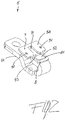
Figure 2 is a perspective view of an embodiment of the fixed contact assembly in a low voltage switch pole, according to the invention; -
Figure 3 is an exploded view of an embodiment of the fixed contact assembly in a low voltage switch pole, according to the invention; - With reference to the attached Figures, the low voltage switch pole according to the invention, designated with the reference numeral 1, comprises in its more general definition, an
insulating casing 2 defining an internal space. In the embodiment shown infigure 1 , a double interruption switch pole is represented. The present invention is not intended to be limited to such double-interruption switching technology, but it is of more general applicability. - With particular reference to
figure 1 , in the internal space of thecasing 2 of the low voltage switch 1 there are provided one ormore contact areas 3, 30 and a corresponding one or more arcextinguishing areas 4, 40. - A
fixed contact assembly movable contact assembly 6, 60 are positioned incorresponding contact areas 3, 30. According to known technical solutions, themovable contact assembly 6, 60 is movable between a closed position, in which it is into contact with saidfixed contact assembly fixed contact assembly - An
arc chamber extinguishing area 4, 40. - In general, the operating principles and functioning, as well as the related components and mechanisms, of the a low voltage switch used in the present invention can be of the conventional type and will not be described in further details.
- With reference also to
figures 2 and3 , one of the distinguishing features of the low voltage switch 1 of the present invention is given by the fact that saidfixed contact assembly contact support contact surface contact surface movable contact assembly 6, 60 in the closed position and is spaced apart therefrom in the open position of the switch 1. - The
fixed contact assembly conductive expansion plate 53, 530 - which is also positioned on saidcontact support 51, 510 - and which extends towardsaid arc chamber - A further distinguishing features of the low voltage switch 1 of the present invention is given by the fact that said
fixed contact assembly plate 54, 540 which is directly mounted on saidconductive expansion plate - As shown in the attached figures, the
conductive expansion plate plate 54, 540 positioned thereon extend beyond saidcontact area 3, 30 and below saidarc chamber contact areas 3, 30 to the arcextinguishing areas 4, 40. - In the embodiment shown in the attached figures, the area subtended by the gasifying
plate 54, 540 is greater than the area subtended by theconductive expansion plate plate 54, 540 is mounted on theconductive expansion plate plate 54, 540 protrudes beyond the outer perimeter of saidconductive expansion plate - In a preferred embodiment of the voltage switch pole 1, according to the invention, the
gasifying plate 54, 540 is provided with afirst part 7 which is positioned on saidconductive expansion plate conductive expansion plate figures 2 and3 , said gasifyingplate 54, 540 has afirst cutout portion 71 at the center of saidfirst part 7 which leaves uncovered a central portion of saidconductive expansion plate - In another embodiment of the low voltage switch pole 1, according to the invention, the
gasifying plate 54, 540 is provided with afirst part 7 which is positioned on saidconductive expansion plate conductive expansion plate figures 2 and3 , said gasifyingplate 54, 540 is also provided with asecond part 8 surrounding saidcontact surface - In a further embodiment of the low voltage switch pole 1, according to the invention, the gasifying
plate 54, 540 is substantially T shaped and is provided with afirst part 7 which is positioned on saidconductive expansion plate conductive expansion plate figures 2 and3 , said gasifyingplate 54, 540 is also conveniently provided with asecond part 8 which extends perpendicularly from saidfirst portion 7 in the direction of saidcontact surface arc extinguishing area 4, 40. - In this latter embodiment of a low voltage switch pole 1 of the present invention, said gasifying
plate 54, 540 has conveniently afirst cutout portion 71 at the center of saidfirst part 7 which leaves uncovered a central portion of saidconductive expansion plate plate 54, 540 has also asecond cutout portion 81 at the center of saidsecond part 8, thereby providing a seta for saidcontact surface second cutout portion 81. - In the embodiment of the low voltage switch pole 1 shown in the attached figures, said
second cutout portion 81 of saidsecond part 8 of said gasifyingplate 54, 540 is wider than saidfirst cutout portion 71 of saidfirst part 7 of said gasifyingplate 54, 540. - Likewise, in such embodiment, said
first part 7 of said gasifyingplate 54, 540 is wider than saidsecond part 8 of said gasifyingplate 54, 540. A different choice of shape and dimensions of gasifyingplate 54, 540, as well as of theconductive expansion plate - In atypical embodiment of a low voltage switch pole 1, according to the invention, said
conductive expansion plate plate 54, 540 can be provided with suitable retaining means for fixing said gasifyingplate 54, 540 onto saidconductive expansion plate - For instance, with reference to the attached figures, the low voltage switch pole 1 according to the invention, can be provided with retaining means which comprise one or more engagement pins 91 positioned, e.g., on said
conductive expansion plate more engagement seats 92 for saidpins 91 which are positioned, e.g., on the gasifyingplate 54, 540. - An alternative layout, i.e. with the
pins 91 positioned on the gasifyingplate 54, 540 and the corresponding one ormore engagement seats 92 for saidpins 91 which are positioned on saidconductive expansion plate - It is clear from the above that the low voltage switch pole 1 of the present invention allows solving the above underlined problems. Indeed, thanks to the proper layout of the contact area and arc extinguishing area, and in particular thanks to the proper positioning of the gasifying plate, in the low voltage switch pole 1 of the present invention there an increased gasification effect and an increased arc quenching effect, compared with the more conventional solutions of the prior art switches.
- Moreover, the low voltage switch pole 1 is very simple from a mechanical standpoint and requires a limited number of components, thereby not affecting negatively the overall costs of the circuit breaker.
- Several variations can be made to the low voltage switch pole 1, as well as to the low voltage switch comprising such pole, thus conceived, all falling within the scope of the attached claims. In practice, the materials used and the contingent dimensions and shapes can be any, according to requirements and to the state of the art.
Claims (12)
- A low voltage switch pole (1) comprising an insulating casing (2) defining an internal space with a contact area (3, 30) and an arc extinguishing area (4, 40), a fixed contact assembly (5, 50) and a movable contact assembly (6, 60) being positioned in said contact area (3, 30), said movable contact assembly (6, 60) being movable between a closed position in which it is into contact with said fixed contact assembly (5, 50) and an open position in which it is spaced apart from said fixed contact assembly (5, 50), an arc chamber (41, 410) comprising a plurality of substantially parallel metallic plates being positioned in said arc extinguishing area (4, 40), characterized in that said fixed contact assembly (5, 50) is provided with a contact support (51, 510), a contact surface (52, 520) contacting said movable contact assembly (6, 60) in the closed position and positioned on said contact support (51, 510), and a conductive expansion plate (53, 530) positioned on said contact support (51, 510) and extending toward said arc chamber (41, 410), and further characterized in that said fixed contact assembly (5, 50) is provided with a gasifying plate (54, 540) which is directly mounted on said conductive expansion plate (53, 530).
- A low voltage switch pole (1), according to claim 1, characterized in that said conductive expansion plate (53, 530) and said gasifying plate (54, 540) extend beyond said contact area (3, 30) and below said arc chamber (41, 410).
- A low voltage switch pole (1), according to claim 1 or 2, characterized in that said gasifying plate (54, 540) protrudes beyond the outer perimeter of said conductive expansion plate (53, 530).
- A low voltage switch pole (1), according to one or more of the previous claims, characterized in that said gasifying plate (54, 540) has a first part (7) positioned on said conductive expansion plate (53, 530) and protruding beyond the outer perimeter of said conductive expansion plate (53, 530), said gasifying plate (54, 540) having a first cutout portion (71) at the centre of said first part (7) leaving uncovered a central portion of said conductive expansion plate (53, 530).
- A low voltage switch pole (1), according to one or more of the previous claims, characterized in that said gasifying plate (54, 540) has a first part (7) positioned on said conductive expansion plate (53, 530) and protruding beyond the outer perimeter of said conductive expansion plate (53, 530), and a second part (8) surrounding said contact surface (52, 520).
- A low voltage switch pole (1), according to one or more of the previous claims, characterized in that said gasifying plate (54, 540) is substantially T shaped and has a first part (7) positioned on said conductive expansion plate (53, 530) and protruding beyond the outer perimeter of said conductive expansion plate (53, 530), and a second part (8) perpendicularly extending from said first portion (7) in the direction of said contact surface (52, 520).
- A low voltage switch pole (1), according to claim 6, characterized in that said gasifying plate (54, 540) has a first cutout portion (71) at the centre of said first part (7) leaving uncovered a central portion of said conductive expansion plate (53, 530) and a second cutout portion (81) at the centre of said second part (8), said contact surface (52, 520) being at least partially positioned within said second cutout portion (81).
- A low voltage switch pole (1), according to claim 7, characterized in that said second cutout portion (81) of said second part (8) of said gasifying plate (54, 540) is wider than said first cutout portion (71) of said first part (7) of said gasifying plate (54, 540).
- A low voltage switch pole (1), according to claim 7 or 8, characterized in that said first part (7) of said gasifying plate (54, 540) is wider than said second part (8) of said gasifying plate (54, 540).
- A low voltage switch pole (1), according to one or more of the previous claims, characterized in that said conductive expansion plate (53, 530) and said gasifying plate (54, 540) are provided with retaining means for fixing said gasifying plate (54, 540) onto said conductive expansion plate (53, 530).
- A low voltage switch pole (1), according to claim 10, characterized in that said retaining means comprise one or more engagement pins (91) positioned on one of said conductive expansion plate (53, 530) or gasifying plate (54, 540) and corresponding one or more engagement seats (92) for said pins (91) positioned on the other of said conductive expansion plate (53, 530) or gasifying plate (54, 540).
- A low voltage switch comprising a switch pole (1), according to one or more of the previous claims.
Priority Applications (3)
| Application Number | Priority Date | Filing Date | Title |
|---|---|---|---|
| EP19189944.2A EP3772742B1 (en) | 2019-08-05 | 2019-08-05 | Low voltage switch pole |
| CN202010722815.6A CN112331536B (en) | 2019-08-05 | 2020-07-24 | Low-voltage switch pole |
| US16/985,282 US11355290B2 (en) | 2019-08-05 | 2020-08-05 | Low voltage switch pole |
Applications Claiming Priority (1)
| Application Number | Priority Date | Filing Date | Title |
|---|---|---|---|
| EP19189944.2A EP3772742B1 (en) | 2019-08-05 | 2019-08-05 | Low voltage switch pole |
Publications (3)
| Publication Number | Publication Date |
|---|---|
| EP3772742A1 true EP3772742A1 (en) | 2021-02-10 |
| EP3772742C0 EP3772742C0 (en) | 2025-04-23 |
| EP3772742B1 EP3772742B1 (en) | 2025-04-23 |
Family
ID=67544089
Family Applications (1)
| Application Number | Title | Priority Date | Filing Date |
|---|---|---|---|
| EP19189944.2A Active EP3772742B1 (en) | 2019-08-05 | 2019-08-05 | Low voltage switch pole |
Country Status (3)
| Country | Link |
|---|---|
| US (1) | US11355290B2 (en) |
| EP (1) | EP3772742B1 (en) |
| CN (1) | CN112331536B (en) |
Families Citing this family (2)
| Publication number | Priority date | Publication date | Assignee | Title |
|---|---|---|---|---|
| CA3201024A1 (en) * | 2022-05-30 | 2023-11-30 | Axle Spindle Inc. | Spindle repair apparatus and method |
| US20250095931A1 (en) * | 2023-09-14 | 2025-03-20 | Eaton Intelligent Power Limited | Modular electrical switch apparatus and electrical switch base |
Citations (4)
| Publication number | Priority date | Publication date | Assignee | Title |
|---|---|---|---|---|
| JPH07302535A (en) * | 1994-03-10 | 1995-11-14 | Mitsubishi Electric Corp | Arc extinguishing insulating material composition, arc extinguishing insulating material molded article, and arc extinguishing apparatus using the same |
| JP2006059759A (en) * | 2004-08-23 | 2006-03-02 | Fuji Electric Holdings Co Ltd | Circuit breaker arc extinguishing device |
| JP2006059758A (en) * | 2004-08-23 | 2006-03-02 | Fuji Electric Fa Components & Systems Co Ltd | Circuit breaker arc extinguishing device |
| CN103762130A (en) * | 2013-12-27 | 2014-04-30 | 常熟开关制造有限公司(原常熟开关厂) | Breaker |
Family Cites Families (10)
| Publication number | Priority date | Publication date | Assignee | Title |
|---|---|---|---|---|
| JPS5975517A (en) * | 1982-10-22 | 1984-04-28 | 三菱電機株式会社 | Switch |
| FR2650434B1 (en) * | 1989-07-26 | 1995-11-24 | Merlin Gerin | LOW VOLTAGE CIRCUIT BREAKER WITH MULTIPLE CONTACTS AND HIGH CURRENTS |
| IT1264164B1 (en) * | 1993-04-21 | 1996-09-17 | Sace Spa | LOW VOLTAGE SWITCH IN INSULATING BOX |
| US6417474B1 (en) * | 2001-05-15 | 2002-07-09 | Eaton Corporation | Electrical switching apparatus having an arc runner with an elongated raised ridge |
| ITMI20012327A1 (en) * | 2001-11-06 | 2003-05-06 | Abb Service Srl | LOW VOLTAGE SWITCH |
| ITMI20012586A1 (en) * | 2001-12-10 | 2003-06-10 | Abb Service Srl | ELECTRIC POLE FOR A LOW VOLTAGE POWER SWITCH, AND RELATED SWITCH |
| NZ573217A (en) * | 2006-05-05 | 2011-11-25 | Plascoenergy Ip Holdings S L Bilbao Schaffhausen Branch | A facility for conversion of carbonaceous feedstock into a reformulated syngas containing CO and H2 |
| US7863537B2 (en) * | 2007-10-09 | 2011-01-04 | Eaton Corporation | Gassing insulator assembly, and conductor assembly and electrical switching apparatus employing the same |
| JP5682450B2 (en) * | 2011-05-23 | 2015-03-11 | 富士電機機器制御株式会社 | Circuit breaker |
| CN103047646B (en) * | 2013-01-18 | 2015-07-01 | 湖南名诚新能源有限公司 | Liquid alcohol base fuel vaporizing burner |
-
2019
- 2019-08-05 EP EP19189944.2A patent/EP3772742B1/en active Active
-
2020
- 2020-07-24 CN CN202010722815.6A patent/CN112331536B/en active Active
- 2020-08-05 US US16/985,282 patent/US11355290B2/en active Active
Patent Citations (4)
| Publication number | Priority date | Publication date | Assignee | Title |
|---|---|---|---|---|
| JPH07302535A (en) * | 1994-03-10 | 1995-11-14 | Mitsubishi Electric Corp | Arc extinguishing insulating material composition, arc extinguishing insulating material molded article, and arc extinguishing apparatus using the same |
| JP2006059759A (en) * | 2004-08-23 | 2006-03-02 | Fuji Electric Holdings Co Ltd | Circuit breaker arc extinguishing device |
| JP2006059758A (en) * | 2004-08-23 | 2006-03-02 | Fuji Electric Fa Components & Systems Co Ltd | Circuit breaker arc extinguishing device |
| CN103762130A (en) * | 2013-12-27 | 2014-04-30 | 常熟开关制造有限公司(原常熟开关厂) | Breaker |
Also Published As
| Publication number | Publication date |
|---|---|
| EP3772742C0 (en) | 2025-04-23 |
| US20210043396A1 (en) | 2021-02-11 |
| EP3772742B1 (en) | 2025-04-23 |
| CN112331536B (en) | 2025-07-08 |
| US11355290B2 (en) | 2022-06-07 |
| CN112331536A (en) | 2021-02-05 |
Similar Documents
| Publication | Publication Date | Title |
|---|---|---|
| RU2694433C2 (en) | Low-voltage switch pole and low-voltage switch with such pole | |
| EP2393095B1 (en) | Mold cased circuit breaker | |
| US8237074B2 (en) | Switching device | |
| EP3667690B1 (en) | Molded case circuit breaker | |
| CN101436474A (en) | Electrical switching apparatus, and arc hood assembly and chimney therefor | |
| US11355290B2 (en) | Low voltage switch pole | |
| KR20180124825A (en) | Arc Extinguishing Unit of Air Circuit Breaker for Direct Current | |
| KR20140036111A (en) | Arc extinguishing mechanism of direct current switch and direct current switch and direct current circuit breaker having arc extinguishing mechanism | |
| US9147541B2 (en) | Circuit breaker comprising ventilation channels for efficient heat dissipation | |
| EP3734631B1 (en) | Dc circuit breaker | |
| KR102685858B1 (en) | Arc Extinguishing Unit of Molded Case Circuit Breaker | |
| KR20200009391A (en) | Arc Extinguishing Unit of Molded Case Circuit Breaker | |
| CN112309783B (en) | Door phase separation device in molded case circuit breaker | |
| EP1471553B1 (en) | Air circuit breaker | |
| CN107533930A (en) | Switchgear with arc-control device | |
| CN110753984B (en) | Improved circuit breaker for high DC current or voltage applications, such as industrial and/or railway applications | |
| KR20150089729A (en) | Arc Extinguishing Device of Molded Case Circuit Breaker | |
| CN113471032A (en) | Electromechanical compact protective switching device | |
| JP7771736B2 (en) | circuit breaker | |
| EP4415014A1 (en) | Low-voltage switch pole | |
| KR20200111013A (en) | Molded Case Circuit Breaker | |
| EP1346385B1 (en) | Automatic current limiting circuit breaker | |
| CN114649165A (en) | Circuit breaker structure capable of improving breaking capacity | |
| JP2022538442A (en) | electrical switching system | |
| KR20190002093U (en) | Distinguishing Unit of Molded Case Circuit Breaker |
Legal Events
| Date | Code | Title | Description |
|---|---|---|---|
| PUAI | Public reference made under article 153(3) epc to a published international application that has entered the european phase |
Free format text: ORIGINAL CODE: 0009012 |
|
| STAA | Information on the status of an ep patent application or granted ep patent |
Free format text: STATUS: THE APPLICATION HAS BEEN PUBLISHED |
|
| AK | Designated contracting states |
Kind code of ref document: A1 Designated state(s): AL AT BE BG CH CY CZ DE DK EE ES FI FR GB GR HR HU IE IS IT LI LT LU LV MC MK MT NL NO PL PT RO RS SE SI SK SM TR |
|
| AX | Request for extension of the european patent |
Extension state: BA ME |
|
| STAA | Information on the status of an ep patent application or granted ep patent |
Free format text: STATUS: REQUEST FOR EXAMINATION WAS MADE |
|
| 17P | Request for examination filed |
Effective date: 20210810 |
|
| RBV | Designated contracting states (corrected) |
Designated state(s): AL AT BE BG CH CY CZ DE DK EE ES FI FR GB GR HR HU IE IS IT LI LT LU LV MC MK MT NL NO PL PT RO RS SE SI SK SM TR |
|
| STAA | Information on the status of an ep patent application or granted ep patent |
Free format text: STATUS: EXAMINATION IS IN PROGRESS |
|
| 17Q | First examination report despatched |
Effective date: 20230414 |
|
| GRAP | Despatch of communication of intention to grant a patent |
Free format text: ORIGINAL CODE: EPIDOSNIGR1 |
|
| STAA | Information on the status of an ep patent application or granted ep patent |
Free format text: STATUS: GRANT OF PATENT IS INTENDED |
|
| INTG | Intention to grant announced |
Effective date: 20241202 |
|
| GRAS | Grant fee paid |
Free format text: ORIGINAL CODE: EPIDOSNIGR3 |
|
| GRAA | (expected) grant |
Free format text: ORIGINAL CODE: 0009210 |
|
| STAA | Information on the status of an ep patent application or granted ep patent |
Free format text: STATUS: THE PATENT HAS BEEN GRANTED |
|
| AK | Designated contracting states |
Kind code of ref document: B1 Designated state(s): AL AT BE BG CH CY CZ DE DK EE ES FI FR GB GR HR HU IE IS IT LI LT LU LV MC MK MT NL NO PL PT RO RS SE SI SK SM TR |
|
| REG | Reference to a national code |
Ref country code: GB Ref legal event code: FG4D |
|
| REG | Reference to a national code |
Ref country code: CH Ref legal event code: EP |
|
| REG | Reference to a national code |
Ref country code: DE Ref legal event code: R096 Ref document number: 602019068928 Country of ref document: DE |
|
| REG | Reference to a national code |
Ref country code: IE Ref legal event code: FG4D |
|
| U01 | Request for unitary effect filed |
Effective date: 20250512 |
|
| U07 | Unitary effect registered |
Designated state(s): AT BE BG DE DK EE FI FR IT LT LU LV MT NL PT RO SE SI Effective date: 20250516 |
|
| U20 | Renewal fee for the european patent with unitary effect paid |
Year of fee payment: 7 Effective date: 20250827 |
|
| PG25 | Lapsed in a contracting state [announced via postgrant information from national office to epo] |
Ref country code: ES Free format text: LAPSE BECAUSE OF FAILURE TO SUBMIT A TRANSLATION OF THE DESCRIPTION OR TO PAY THE FEE WITHIN THE PRESCRIBED TIME-LIMIT Effective date: 20250423 |
|
| PG25 | Lapsed in a contracting state [announced via postgrant information from national office to epo] |
Ref country code: GR Free format text: LAPSE BECAUSE OF FAILURE TO SUBMIT A TRANSLATION OF THE DESCRIPTION OR TO PAY THE FEE WITHIN THE PRESCRIBED TIME-LIMIT Effective date: 20250724 Ref country code: NO Free format text: LAPSE BECAUSE OF FAILURE TO SUBMIT A TRANSLATION OF THE DESCRIPTION OR TO PAY THE FEE WITHIN THE PRESCRIBED TIME-LIMIT Effective date: 20250723 |
|
| PG25 | Lapsed in a contracting state [announced via postgrant information from national office to epo] |
Ref country code: PL Free format text: LAPSE BECAUSE OF FAILURE TO SUBMIT A TRANSLATION OF THE DESCRIPTION OR TO PAY THE FEE WITHIN THE PRESCRIBED TIME-LIMIT Effective date: 20250423 |
|
| PG25 | Lapsed in a contracting state [announced via postgrant information from national office to epo] |
Ref country code: HR Free format text: LAPSE BECAUSE OF FAILURE TO SUBMIT A TRANSLATION OF THE DESCRIPTION OR TO PAY THE FEE WITHIN THE PRESCRIBED TIME-LIMIT Effective date: 20250423 |
|
| PG25 | Lapsed in a contracting state [announced via postgrant information from national office to epo] |
Ref country code: RS Free format text: LAPSE BECAUSE OF FAILURE TO SUBMIT A TRANSLATION OF THE DESCRIPTION OR TO PAY THE FEE WITHIN THE PRESCRIBED TIME-LIMIT Effective date: 20250723 |
|
| PG25 | Lapsed in a contracting state [announced via postgrant information from national office to epo] |
Ref country code: IS Free format text: LAPSE BECAUSE OF FAILURE TO SUBMIT A TRANSLATION OF THE DESCRIPTION OR TO PAY THE FEE WITHIN THE PRESCRIBED TIME-LIMIT Effective date: 20250823 |
|
| PG25 | Lapsed in a contracting state [announced via postgrant information from national office to epo] |
Ref country code: SM Free format text: LAPSE BECAUSE OF FAILURE TO SUBMIT A TRANSLATION OF THE DESCRIPTION OR TO PAY THE FEE WITHIN THE PRESCRIBED TIME-LIMIT Effective date: 20250423 |
|
| PG25 | Lapsed in a contracting state [announced via postgrant information from national office to epo] |
Ref country code: CZ Free format text: LAPSE BECAUSE OF FAILURE TO SUBMIT A TRANSLATION OF THE DESCRIPTION OR TO PAY THE FEE WITHIN THE PRESCRIBED TIME-LIMIT Effective date: 20250423 |
|
| PG25 | Lapsed in a contracting state [announced via postgrant information from national office to epo] |
Ref country code: SK Free format text: LAPSE BECAUSE OF FAILURE TO SUBMIT A TRANSLATION OF THE DESCRIPTION OR TO PAY THE FEE WITHIN THE PRESCRIBED TIME-LIMIT Effective date: 20250423 |
|
| PLBE | No opposition filed within time limit |
Free format text: ORIGINAL CODE: 0009261 |
|
| STAA | Information on the status of an ep patent application or granted ep patent |
Free format text: STATUS: NO OPPOSITION FILED WITHIN TIME LIMIT |
|
| REG | Reference to a national code |
Ref country code: CH Ref legal event code: L10 Free format text: ST27 STATUS EVENT CODE: U-0-0-L10-L00 (AS PROVIDED BY THE NATIONAL OFFICE) Effective date: 20260304 |
|
| REG | Reference to a national code |
Ref country code: CH Ref legal event code: H13 Free format text: ST27 STATUS EVENT CODE: U-0-0-H10-H13 (AS PROVIDED BY THE NATIONAL OFFICE) Effective date: 20260324 |
|
| PG25 | Lapsed in a contracting state [announced via postgrant information from national office to epo] |
Ref country code: MC Free format text: LAPSE BECAUSE OF FAILURE TO SUBMIT A TRANSLATION OF THE DESCRIPTION OR TO PAY THE FEE WITHIN THE PRESCRIBED TIME-LIMIT Effective date: 20250423 |
|
| 26N | No opposition filed |
Effective date: 20260126 |
|
| PG25 | Lapsed in a contracting state [announced via postgrant information from national office to epo] |
Ref country code: CH Free format text: LAPSE BECAUSE OF NON-PAYMENT OF DUE FEES Effective date: 20250831 |
|
| GBPC | Gb: european patent ceased through non-payment of renewal fee |
Effective date: 20250805 |