EP3772707A1 - Dynamics model for globally stable modeling of system dynamics - Google Patents

Dynamics model for globally stable modeling of system dynamics Download PDF

Info

Publication number
EP3772707A1
EP3772707A1 EP19190105.7A EP19190105A EP3772707A1 EP 3772707 A1 EP3772707 A1 EP 3772707A1 EP 19190105 A EP19190105 A EP 19190105A EP 3772707 A1 EP3772707 A1 EP 3772707A1
Authority
EP
European Patent Office
Prior art keywords
dynamics
physical system
learned
dynamics model
model
Prior art date
Legal status (The legal status is an assumption and is not a legal conclusion. Google has not performed a legal analysis and makes no representation as to the accuracy of the status listed.)
Pending
Application number
EP19190105.7A
Other languages
German (de)
French (fr)
Inventor
Jeremy Zieg Kolter
Gaurav Manek
Julia VINOGRADSKA
Current Assignee (The listed assignees may be inaccurate. Google has not performed a legal analysis and makes no representation or warranty as to the accuracy of the list.)
Robert Bosch GmbH
Carnegie Mellon University
Original Assignee
Robert Bosch GmbH
Carnegie Mellon University
Priority date (The priority date is an assumption and is not a legal conclusion. Google has not performed a legal analysis and makes no representation as to the accuracy of the date listed.)
Filing date
Publication date
Application filed by Robert Bosch GmbH, Carnegie Mellon University filed Critical Robert Bosch GmbH
Priority to EP19190105.7A priority Critical patent/EP3772707A1/en
Priority to US16/933,245 priority patent/US11886782B2/en
Priority to CN202010771556.6A priority patent/CN112327612A/en
Publication of EP3772707A1 publication Critical patent/EP3772707A1/en
Pending legal-status Critical Current

Links

Images

Classifications

    • GPHYSICS
    • G06COMPUTING; CALCULATING OR COUNTING
    • G06FELECTRIC DIGITAL DATA PROCESSING
    • G06F30/00Computer-aided design [CAD]
    • G06F30/20Design optimisation, verification or simulation
    • G06F30/27Design optimisation, verification or simulation using machine learning, e.g. artificial intelligence, neural networks, support vector machines [SVM] or training a model
    • GPHYSICS
    • G05CONTROLLING; REGULATING
    • G05BCONTROL OR REGULATING SYSTEMS IN GENERAL; FUNCTIONAL ELEMENTS OF SUCH SYSTEMS; MONITORING OR TESTING ARRANGEMENTS FOR SUCH SYSTEMS OR ELEMENTS
    • G05B13/00Adaptive control systems, i.e. systems automatically adjusting themselves to have a performance which is optimum according to some preassigned criterion
    • G05B13/02Adaptive control systems, i.e. systems automatically adjusting themselves to have a performance which is optimum according to some preassigned criterion electric
    • G05B13/04Adaptive control systems, i.e. systems automatically adjusting themselves to have a performance which is optimum according to some preassigned criterion electric involving the use of models or simulators
    • G05B13/042Adaptive control systems, i.e. systems automatically adjusting themselves to have a performance which is optimum according to some preassigned criterion electric involving the use of models or simulators in which a parameter or coefficient is automatically adjusted to optimise the performance
    • GPHYSICS
    • G06COMPUTING; CALCULATING OR COUNTING
    • G06NCOMPUTING ARRANGEMENTS BASED ON SPECIFIC COMPUTATIONAL MODELS
    • G06N3/00Computing arrangements based on biological models
    • G06N3/02Neural networks
    • G06N3/08Learning methods
    • GPHYSICS
    • G05CONTROLLING; REGULATING
    • G05BCONTROL OR REGULATING SYSTEMS IN GENERAL; FUNCTIONAL ELEMENTS OF SUCH SYSTEMS; MONITORING OR TESTING ARRANGEMENTS FOR SUCH SYSTEMS OR ELEMENTS
    • G05B13/00Adaptive control systems, i.e. systems automatically adjusting themselves to have a performance which is optimum according to some preassigned criterion
    • G05B13/02Adaptive control systems, i.e. systems automatically adjusting themselves to have a performance which is optimum according to some preassigned criterion electric
    • G05B13/0265Adaptive control systems, i.e. systems automatically adjusting themselves to have a performance which is optimum according to some preassigned criterion electric the criterion being a learning criterion
    • G05B13/027Adaptive control systems, i.e. systems automatically adjusting themselves to have a performance which is optimum according to some preassigned criterion electric the criterion being a learning criterion using neural networks only
    • GPHYSICS
    • G05CONTROLLING; REGULATING
    • G05BCONTROL OR REGULATING SYSTEMS IN GENERAL; FUNCTIONAL ELEMENTS OF SUCH SYSTEMS; MONITORING OR TESTING ARRANGEMENTS FOR SUCH SYSTEMS OR ELEMENTS
    • G05B13/00Adaptive control systems, i.e. systems automatically adjusting themselves to have a performance which is optimum according to some preassigned criterion
    • G05B13/02Adaptive control systems, i.e. systems automatically adjusting themselves to have a performance which is optimum according to some preassigned criterion electric
    • G05B13/04Adaptive control systems, i.e. systems automatically adjusting themselves to have a performance which is optimum according to some preassigned criterion electric involving the use of models or simulators
    • G05B13/048Adaptive control systems, i.e. systems automatically adjusting themselves to have a performance which is optimum according to some preassigned criterion electric involving the use of models or simulators using a predictor
    • GPHYSICS
    • G06COMPUTING; CALCULATING OR COUNTING
    • G06NCOMPUTING ARRANGEMENTS BASED ON SPECIFIC COMPUTATIONAL MODELS
    • G06N20/00Machine learning
    • GPHYSICS
    • G06COMPUTING; CALCULATING OR COUNTING
    • G06NCOMPUTING ARRANGEMENTS BASED ON SPECIFIC COMPUTATIONAL MODELS
    • G06N3/00Computing arrangements based on biological models
    • G06N3/02Neural networks
    • G06N3/04Architecture, e.g. interconnection topology
    • G06N3/045Combinations of networks
    • GPHYSICS
    • G06COMPUTING; CALCULATING OR COUNTING
    • G06NCOMPUTING ARRANGEMENTS BASED ON SPECIFIC COMPUTATIONAL MODELS
    • G06N3/00Computing arrangements based on biological models
    • G06N3/02Neural networks
    • G06N3/04Architecture, e.g. interconnection topology
    • G06N3/048Activation functions
    • GPHYSICS
    • G06COMPUTING; CALCULATING OR COUNTING
    • G06NCOMPUTING ARRANGEMENTS BASED ON SPECIFIC COMPUTATIONAL MODELS
    • G06N5/00Computing arrangements using knowledge-based models
    • G06N5/04Inference or reasoning models
    • G06N5/046Forward inferencing; Production systems

Definitions

  • the invention relates to a machine learning system and computer-implemented method for training a dynamics model to learn dynamics of a physical system.
  • the invention further relates to a trained dynamics model.
  • the invention further relates to a control or monitoring system and computer-implemented method for controlling or monitoring a physical system using a machine learned modelling of dynamics of the physical system.
  • the invention further relates to a computer-readable medium comprising instructions for performing one of the computer-implemented methods.
  • neural networks are a promising approach to learn the transformation from observation space to the latent, physically meaningful low-dimensional space of the system dynamics of the physical system, and may also be referred to as machine learned dynamics models.
  • An example of such a real-life application is the manufacturing of electronic components, where two parts may need to be connected by first bonding a copper wire to one component, then bending the wire into place and, finally, bonding the copper wire to the second component.
  • the bending of the wire may be performed by an arm of a robot.
  • the bending process cannot be hardcoded but is preferably learned based on sensor input.
  • sensors that measure the physically relevant low-dimensional state of the system e.g., angles, angular velocities, joint positions
  • a machine learning system and corresponding computer-implemented method are provided for training a dynamics model to learn dynamics of a physical system, as defined by claim 1 and 10, respectively.
  • a computer-implemented method and a corresponding control or monitoring system are provided for controlling or monitoring a physical system using a machine learned modelling of dynamics of the physical system, as defined by claim 11 and 13, respectively.
  • a computer-readable medium is provided comprising transitory or non-transitory data representing model data defining a learned dynamics model, as defined by claim 9.
  • a computer-readable medium is provided comprising data representing instructions arranged to cause a processor system to perform the computer-implemented method of claim 10 or 11.
  • the above measures may involve training a dynamics model to learn the dynamics of the physical system.
  • the dynamics model may be learned to be able to infer a future state of the physical system and/or its environment based on a current state of, respectively, the physical system and/or its environment.
  • a state of the physical system may be expressed in various ways.
  • the state of the robotic arm may be expressed as angles, angular velocities, joint positions, etc., or in general may be represented by known physical quantities.
  • the training data may contain direct observations of such known physical quantities.
  • the state of the physical system may be observed in a high-dimensional observation space, e.g., as video data, which may be transformed to a latent, physically meaningful low-dimensional space using a transformation.
  • the states of the physical system and thereby the training data may be represented as latent samples in the obtained low-dimensional space, and may, but do not need to, correspond to known physical quantities. It is known to learn such transformation by machine learning, e.g., using Variational Auto Encoders (VAEs).
  • VAEs Variational Auto Encoders
  • the transformation may be learned by the dynamics model itself in that the training data may comprise indirect observations of physically meaningful quantities, e.g., in a high-dimensional observation space.
  • the dynamics of a physical system may in many cases also be learned from a state of the environment of the physical system, instead or in addition to learning the dynamics from the state of the physical system itself.
  • the steering dynamics of an autonomous vehicle may be learned from a video camera mounted in the autonomous vehicle which is directed towards the road ahead of the vehicle.
  • training data may be accessed which defines a time-series of states x ( t ) of the physical system and/or its environment. It is known per se to train a dynamics model to learn the dynamics of a physical system using such training data. Namely, the training data may provide time-sequential pairs of states, with each pair being formed by a current state and a future state of the physical system, with the former being an input and the latter being a target output of the dynamics model in the model's training.
  • the above measures may ensure global stability of the learned dynamics model f ( x ( t )) by way of a Lyapunov function V ( x ( t )).
  • a Lyapunov function is a particular type of function that connects a descent in its function values along trajectories of the dynamics f with the different types of stability.
  • the initial state x 0 and f ( x ) may together define a state evolution x ( t ), t ⁇ [0; T ] or x 0 , x 1 ,..., x T in discrete-time.
  • This state evolution may represent a trajectory of f ( x ), and decreasing along all trajectories of f may mean that for any x 0 and any T , it holds that: ⁇ V ( x ( t )) ⁇ 0 or V ( x t +1 ) ⁇ V ( x t ).
  • the Lyapunov function may be learned as well, e.g., using a neural network.
  • the above measures instead of learning a dynamics model and attempting to separately verify its stability via a (learned) Lyapunov function, the above measures jointly learn a dynamics model and Lyapunov function, where the dynamics is inherently constrained to be stable everywhere in the state space according to the Lyapunov function. Accordingly, the learned dynamics model is stable even for states which are not seen during training.
  • the above measures provide a learned dynamics model which is inherently globally stable, instead of being merely incentivized during the training to be globally stable, e.g., via a loss function.
  • the above measures provide a learned dynamics model which is highly suitable for real-life applications in which a physical system may assume a state which was unseen during training as the learned dynamics model is inherently guaranteed to be stable.
  • the dynamics model may be integrated into deep architectures, for example an architecture in which a variational auto-encoder transforms observations from sensor data to a latent, physically meaningful low-dimensional space of the system dynamics of the physical system and which may be used as input to the learned dynamics model to obtain a prediction of a future state of the physical system.
  • This prediction may be used in various control or monitoring applications, for example to control a robotic arm to bend a wire, to control an autonomous vehicle to steer and/or brake, etc.
  • the processor subsystem is configured to jointly learn the dynamics model and the Lyapunov function by learning as the dynamics model ( f ( x t )) a projection ( Proj ) of nominal dynamics ( f ⁇ ( x t )) of the physical system, which are learned based on the time-series of states ( x t ), onto a function that fulfills the Lyapunov condition as defined by the Lyapunov function ( V ( x t )).
  • the nominal dynamics f ⁇ ( x t ) may represent the system dynamics which are learned directly and 'naively' from the training data before projecting, and which may for example be learned by a neural network.
  • the final dynamics f ( x t ) may then be evaluated by projection of f ⁇ ( x t ) onto the set of dynamics that make V ( x t ) a Lyapunov function to ensure global asymptotic stability.
  • the projection ( Proj ) is an orthogonal projection onto a halfspace.
  • Proj ( ⁇ , ⁇ ) may denote an orthogonal projection onto a halfspace.
  • automatic differentiation tools may be used to define V , such that including ⁇ V in the definition of f( x t ) may be done straightforwardly. Thereby, f ( x t ) may be trained straightforwardly, similar to the training of any other dynamics model.
  • the dynamics model ( f ( x )) comprises a neural network for learning the nominal dynamics ( f ⁇ ( x t )) of the physical system based on the time-sequential pairs of states ( x t ).
  • the dynamics model may comprise a neural network for learning the nominal dynamics f ⁇ ( x t ).
  • the dynamics model may thus be comprised of two different neural networks.
  • the machine learnable Lyapunov function ( V ( x t )) is represented at least in part by an input-convex neural network (ICNN, g(x)).
  • the Lyapunov function V ( x t ) may also be learned and represented by a neural network.
  • an input-convex neural network g ( x ) which enforces the condition that g ( x ) is convex in its inputs x , it may be ensured that V ( x t )) has only one global optimum, which is one of the properties of the Lyapunov function which is to be learned by the input-convex neural network.
  • the input-convex neural network (ICNN, g ( x )) comprises a smoothed variant of a rectified linear unit (ReLu) for each of the activation functions.
  • a smoothed variant of the ReLu may ensure that V ( x t ) is continuously differentiable.
  • a linear ReLu may be modified to provide a quadratic function in [0, d ].
  • Positive definitiveness is another property of the Lyapunov function which is to be learned by the input-convex neural network, and which may be ensured by the above measures.
  • the processor subsystem is configured to, when learning the input-convex neural network (ICNN, g ( x )) on the training data ( x t ), apply a continuously differentiable invertible function ( F ( x )) to the training data ( x t ) and use an output of the continuously differential invertible function as an input ( g ( F ( x )) to the input-convex neural network.
  • Invertibility may ensure that the sublevel sets of V , which may be by definition convex sets, map to contiguous regions of the composite function g ⁇ F , thus ensuring that no local optima exist in the composed function and thus that V has only one optimum.
  • the output device is an actuator associated with the physical system
  • the processor subsystem is configured to control the physical system by providing control data to the actuator which is based on the inferred future state ( x t +1 ) of the physical system.
  • the actuator may be used to control a vehicle, such as an autonomous or semi-autonomous vehicle, a robot, a manufacturing machine, a building, etc.
  • control or monitoring system is one of: a vehicle control system, a robotics control system, a manufacturing control system, a building control system.
  • a vehicle control system a robotics control system
  • a manufacturing control system a building control system.
  • the computer-implemented or system for training a machine learnable dynamics model to learn the dynamics of a physical system may further comprise any computer-implemented method or system described in this specification for using the learned dynamics model, for example for control or monitoring of a physical system.
  • Figs. 1 and 2 the training of a learnable dynamics model which comprises a learnable Lyapunov function to establish global stability of the learned dynamics model, then describes with reference to Figs. 3A-5C the dynamics model and its training in more detail, then describes with reference to Fig. 6A-7B applications of the dynamics model which include a comparison to a non-stable dynamics model, and with reference to Figs. 8-10 the use of the learned dynamics model for the control or monitoring of a physical system, such as an (semi-)autonomous vehicle.
  • Fig. 1 shows a system 100 for training a dynamics model to learn dynamics of a physical system by learning to infer a future state of the physical system and/or its environment based on a current state of the physical system and/or its environment.
  • the system 100 may comprise an input interface for accessing training data 192 representing a time-series of states of the physical system and/or its environment and for accessing model data 194 defining a machine learnable dynamics model which comprises a machine learnable Lyapunov function.
  • the input interface may be constituted by a data storage interface 180 which may access the training data 192 and the model data 194 from a data storage 190.
  • the data storage interface 180 may be a memory interface or a persistent storage interface, e.g., a hard disk or an SSD interface, but also a personal, local or wide area network interface such as a Bluetooth, Zigbee or Wi-Fi interface or an ethernet or fiberoptic interface.
  • the data storage 190 may be an internal data storage of the system 100, such as a hard drive or SSD, but also an external data storage, e.g., a network-accessible data storage.
  • the training data 192 and the model data 194 may each be accessed from a different data storage, e.g., via a different subsystem of the data storage interface 180.
  • Each subsystem may be of a type as is described above for the data storage interface 180.
  • the system 100 may further comprise a processor subsystem 160 which may be configured to, during operation of the system 100, to learn the dynamics model based on time-sequential pairs of states so as to learn to infer a future state of the physical system and/or its environment based on the current state, wherein said learning is constrained to provide a globally stable modelling of the dynamics of the physical system by jointly learning the dynamics model and the Lyapunov function so that values of the learned Lyapunov function decrease along all trajectories of states inferred by the learned dynamics model.
  • This dynamics model and its training will be further described with reference to Fig. 3A-5C .
  • the system 100 may further comprise an output interface for outputting trained model data 196 representing the learned (or 'trained') dynamics model.
  • the output interface may be constituted by the data storage interface 180, with said interface being in these embodiments an input/output ('IO') interface, via which the trained model data 196 may be stored in the data storage 190.
  • the model data 194 defining the 'untrained' dynamics model may during or after the training be replaced, at least in part, by the model data 196 of the trained dynamics model, in that the parameters of the dynamics model, such as weights and other types of parameters of neural networks, may be adapted to reflect the training on the training data 192. This is also illustrated in Fig.
  • the trained model data 196 may be stored separately from the model data 194 defining the 'untrained' dynamics model.
  • the output interface may be separate from the data storage interface 180, but may in general be of a type as described above for the data storage interface 180.
  • Fig. 2 shows a computer-implemented method 200 for training a dynamics model to learn dynamics of a physical system by learning infer a future state of the physical system and/or its environment based on a current state of the physical system and/or its environment.
  • the method 200 may correspond to an operation of the system 100 of Fig. 1 , but does not need to, in that it may also correspond to an operation of another type of system, apparatus or device or in that it may correspond to a computer program.
  • the computer-implemented method 200 is shown to comprise, in a step titled "ACCESSING TRAINING DATA", accessing 210 training data representing a time-series of states of the physical system and/or its environment, in a step titled “ACCESSING MODEL DATA DEFINING DYNAMICS MODEL”, accessing 220 model data defining a machine learnable dynamics model which comprises a machine learnable Lyapunov function, in a step titled “LEARNING DYNAMICS MODEL BASED ON TRAINING DATA”, learning 230 the dynamics model based on time-sequential pairs of states so as to learn to infer a future state of the physical system and/or its environment based on the current state, wherein said learning step 230 comprises, in a step or sub-step titled "JOINT LEARNING OF DYNAMICS MODEL WITH LYAPUNOV FUNCTION", constraining the learning to provide a globally stable modelling of the dynamics of the physical system by jointly learning 240 the dynamics model and the Lyapunov
  • machine learnable dynamics model including the training thereof, in more detail.
  • the actual implementation of the machine learnable dynamics model and its training may be carried out in various other ways, e.g., on the basis of analogous mathematical concepts.
  • a Gaussian process or another machine learnable model type may be used to learn the nominal dynamics of the physical system and to learn the Lyapunov function.
  • neural networks have long been a natural choice for modeling the above function.
  • a generic neural network to model dynamics in this setting, very little can be guaranteed about the behavior of the learned system.
  • stability properties of a learned model informally, the tendency of the system to remain within some invariant bounded set.
  • stability properties of neural networks see the aforementioned [1, 2, 3], such work has typically done so by ("softly") enforcing stability as an additional loss term on the training data. Consequently, such work can say little about the stability of the system in unseen states.
  • a Lyapunov function may be provided, which may be based on an input convex neural network, and which may ensure global exponential stability to an equilibrium point while still allowing for expressive dynamics.
  • n-link pendulums e.g., with reference to Figs. 5A-6B
  • VAE variational auto-encoder
  • f is globally (locally, respectively) exponentially stable (e.g., converges to the equilibrium "exponentially quickly") if ⁇ x t ⁇ 2 ⁇ m ⁇ x ( 0 ⁇ 2 e ⁇ ⁇ t for some constants m , ⁇ ⁇ 0 for any x 0 ⁇ R n ( B , respectively).
  • the area of Lyapunov theory establishes the connection between the various types of stability mentioned above and descent according to a particular type of function known as a Lyapunov function.
  • Lyapunov analysis says that f is stable (according to the definitions above) if and only if we can find some function V as above such the value of this function is decreasing along trajectories generated by f.
  • V is globally asymptotically stable if and only if there exists positive definite V such that V ⁇ x t ⁇ ⁇ ⁇ V x t , with c 1 ⁇ x ⁇ 2 2 ⁇ V x ⁇ c 2 ⁇ x ⁇ 2 2 .
  • Proj ( x ; C ) may denote the orthogonal projection of x onto the point C .
  • V may for example be defined using automatic differentiation tools. Accordingly, the gradient ⁇ V term may be included into the definition of f , obtaining a composite neural network for f (e.g., comprising a first neural network for f ⁇ and a second neural network for the Lyapunov function) which may be trained just like any other function.
  • a composite neural network for f e.g., comprising a first neural network for f ⁇ and a second neural network for the Lyapunov function
  • FIGs. 3A-3C provide an illustration of the above.
  • Each of Figs. 3A-3C shows a contour plot 300-304 of a Lyapunov function of a stable dynamics system, in which Fig. 3A illustrates the trajectory of the Lyapunov function by way of an arrow pointing in a direction of increasing value of the Lyapunov function.
  • Let g ( x ) ⁇ V x ⁇ ⁇ V x ⁇ 2 2 ReLU ⁇ V x T f ⁇ x + ⁇ V x .
  • Fig. 3B illustrates f ⁇ ( x ) having a component g ( x ) not in the half space and which may be subtracted to obtain f ( x ), and
  • Fig. 3C illustrates f ⁇ ( x ) being in the half space and returned unchanged.
  • V may need to be positive definite, but additionally V may be preferred to have no local optima except 0.
  • This is due to Lyapunov decrease condition: one may desire to guarantee stability to the equilibrium point x 0, yet the decrease condition imposed upon the dynamics may mean that V may be decreasing along trajectories of f . If V has a local optimum away from the origin, the dynamics may in theory, but may not need to in practice, get stuck in this location; this may manifest itself by the ⁇ ⁇ V x ⁇ 2 2 term going to zero, which may result in the dynamics becoming undefined at the optima.
  • the above conditions may be enforced by design decisions as described below.
  • W i may be real-valued weights mapping from inputs to the i + 1 layer activations
  • U i may be positive weights mapping previously layer activations z i to the next layer
  • b i may be real-valued biases
  • ⁇ i may be convex, monotonically non-decreasing non-linear activations, such as the ReLU or smooth variants thereof.
  • ICNN input-convex neural network
  • V (0) 0.
  • shifting requires finding the optimum during training, which may be computationally expensive while removing the biases may put limitations on the class of variables that can be approximated.
  • V is continuously differentiable, for example by using a smoothed version 410 of the ReLU activations, as shown in Fig. 4B , that replaces the linear ReLU 400, as shown in Fig. 4A , by a quadratic function in [0, d ].
  • ⁇ x ⁇ 0 if x ⁇ 0 / 2 d x 2 if 0 ⁇ x ⁇ d x ⁇ / 2 d otherwise .
  • warping to the input space may be used, such that the input to g is first mapped by any continuously differentiable, invertible function.
  • convexity may ensure that the Lyapunov function have no local optima, this may be a sufficient but not necessary condition, and indeed requiring a strongly convex Lyapunov function may impose too strict a requirement upon the learned dynamics.
  • Invertibility may ensure that the sublevel sets of V (which are convex sets, by definition) may map to contiguous regions of the composite function g ⁇ F , thus ensuring that no local optima exist in this composed function.
  • Figs. 5A-5C relate to the modelling of a physically-based dynamical system, specifically the n -link pendulum.
  • a damped, rigid n-link pendulum's state x may be described by the angular position ⁇ i and angular velocity ⁇ i of each link i.
  • f ⁇ may be a 2 n -100-100-2 n fully connected neural network, and V a 2 n -60-60-1 ICNN, with properties described previously.
  • the models are trained with pairs of data ( x , ⁇ ) produced by the symbolic algebra solver sympy.
  • the dynamics may be learned to accurately predict motion of the pendulum even over long time periods.
  • the learned dynamics may also be evaluated quantitatively while varying n and the time horizon of simulation.
  • Fig. 6A shows a graph 600 showing the prediction error 620 of the angular position ⁇ and angular velocity ⁇ for an 8-link pendulum as a function of timesteps 610
  • Fig. 6B shows a graph 630 showing the average prediction error 650 over 1000 timesteps as a function of a number of links 640 of the pendulum.
  • Both graphs 600, 630 show the errors for both a 'simple' prior art model 660 and a learned dynamics model 670 of a type as described in this specification.
  • the dynamics model 670 is able to capture the contraction in the physical system (implied by conservation of energy) and in fact exhibits decreasing error towards the end of the simulation (true and simulated dynamics are both stable). In comparison, the error in the simple model increases.
  • Figs. 7A-7B relate to another example in which the dynamics model as described in this specification may be used for stable video texture generation, for example using a Variational Autoencoder (VAE) to learn an encoding for images and the stable dynamics model to learn the dynamics in encoding-space.
  • VAE Variational Autoencoder
  • the overall network Given a sequence of frames ( y 0 , y 1 ,...), the overall network may be fed a frame at time t and may be trained to reconstruct the frames at time t and t + 1.
  • the overall network may be trained to minimize both the standard VAE loss (reconstruction error plus a KL divergence term), but also to minimize the reconstruction loss of a next predicted state.
  • the evolution of the latent dynamics may be modeled at z t +1 ⁇ f ( z t ), or more precisely y t +1 ⁇ d ( f ( z t )).
  • z t +1 ⁇ f ( z t )
  • y t +1 ⁇ d ( f ( z t )
  • the overall network may be trained on pairs of successive frames sampled from videos.
  • the dynamics model may be seeded with the encoding of a single frame and the dynamics model may be numerically integrated to obtain a trajectory.
  • the VAE decoder may convert each step of the trajectory into a frame.
  • Fig. 7B shows trajectories projected onto a two-dimensional plane for, from left to right, three different runs of the dynamics model with the stability constraint and for a dynamics model without the stability constraint in the form of a generic neural network.
  • the true latent space is 320-dimensional
  • the trajectories may be projected onto a two-dimensional plane for display.
  • the dynamics quickly diverge and produce a static image
  • Fig. 8 shows a system 800 for controlling or monitoring a physical system using a machine learned modelling of dynamics of the physical system.
  • the system 800 may comprise an input interface 880 for accessing trained model data 196 representing a learned dynamics model as may be generated by the system 100 of Fig. 1 or the method 200 of Fig. 2 or as described elsewhere.
  • the input interface may be constituted by a data storage interface 880 which may access the trained model data 196 from a data storage 890.
  • the input interface 880 and the data storage 890 may be of a same type as described with reference to Fig. 1 for the input interface 180 and the data storage 190.
  • Fig. 1 for the input interface 180 and the data storage 190.
  • the data storage 892 comprising sensor data 822 representing an observation of a current state of the physical system.
  • the sensor data 822 may also be received directly from a sensor 20 via a sensor interface 820 of via another type of interface instead of being accessed from the data storage 890 via the data storage interface 880.
  • the system 800 may further comprise a processor subsystem 860 which may be configured to, during operation of the system 800, infer the future state of the physical system based on the observation of the current state of the physical system as obtained from the sensor data 822, and using an output interface as described elsewhere, provide output data 842 to an output device to enable the control or monitoring of the physical system based on the inferred future state, as also described elsewhere in this specification.
  • a processor subsystem 860 may be configured to, during operation of the system 800, infer the future state of the physical system based on the observation of the current state of the physical system as obtained from the sensor data 822, and using an output interface as described elsewhere, provide output data 842 to an output device to enable the control or monitoring of the physical system based on the inferred future state, as also described elsewhere in this specification.
  • processor subsystem 860 As for the processor subsystem 860 of Fig. 1 . It will be further appreciated that the same considerations and implementation options may in general apply to the system 800 as for the system 100 of Fig. 1 , unless otherwise noted.
  • the system 800 may comprise a sensor data interface 820 for directly accessing sensor data 822 acquired by a sensor 20 in an environment 60.
  • the sensor 20 may but does not need to be part of the system 800.
  • the sensor 20 may have any suitable form, such as an image sensor, a lidar sensor, a radar sensor, a pressure sensor, a contain temperature sensor, etc.
  • the sensor data 822 may sensor measurements of different physical quantities in that it may be obtained from two or more different sensors sensing different physical quantities.
  • the sensor data interface 820 may have any suitable form corresponding in type to the type of sensor, including but not limited to a low-level communication interface, e.g., based on I2C or SPI data communication, or a data storage interface of a type as described above for the data storage interface 880.
  • the system 800 may comprise an actuator interface 840 for providing control data 842 to an actuator 40 in the environment 60.
  • control data 842 may be generated by the processor subsystem 860 to control the actuator 40 based on one or more inferred future states of the physical system, which may be generated using the learned dynamics model.
  • the actuator may be an electric, hydraulic, pneumatic, thermal, magnetic and/or mechanical actuator. Specific yet non-limiting examples include electrical motors, electroactive polymers, hydraulic cylinders, piezoelectric actuators, pneumatic actuators, servomechanisms, solenoids, stepper motors, etc. Such type of control is described with reference to Fig. 9 for an (semi-)autonomous vehicle.
  • the system 800 may comprise an output interface to a rendering device, such as a display, a light source, a loudspeaker, a vibration motor, etc., which may be used to generate a sensory perceptible output signal which may be generated based on one or more inferred future states of the physical system.
  • the sensory perceptible output signal may be directly indicative of the inferred future states of the physical system, but may also represent a derived sensory perceptible output signal, e.g., for use in guidance, navigation or other type of control of the physical system.
  • each system described in this specification may be embodied as, or in, a single device or apparatus, such as a workstation or a server.
  • the device may be an embedded device.
  • the device or apparatus may comprise one or more microprocessors which execute appropriate software.
  • the processor subsystem of the respective system may be embodied by a single Central Processing Unit (CPU), but also by a combination or system of such CPUs and/or other types of processing units.
  • the software may have been downloaded and/or stored in a corresponding memory, e.g., a volatile memory such as RAM or a non-volatile memory such as Flash.
  • the processor subsystem of the respective system may be implemented in the device or apparatus in the form of programmable logic, e.g., as a Field-Programmable Gate Array (FPGA).
  • FPGA Field-Programmable Gate Array
  • each functional unit of the respective system may be implemented in the form of a circuit.
  • the respective system may also be implemented in a distributed manner, e.g., involving different devices or apparatuses, such as distributed local or cloud-based servers.
  • the system 800 may be part of vehicle, robot or similar physical entity, and/or may be represent a control system configured to control the physical entity.
  • Fig. 9 shows an example of the above, in that the system 800 is shown to be a control system of an (semi-)autonomous vehicle 80 operating in an environment 60.
  • the autonomous vehicle 80 may be autonomous in that it may comprise an autonomous driving system or a driving assistant system, with the latter also being referred to as a semiautonomous system.
  • the autonomous vehicle 80 may for example incorporate the system 800 to control the steering and the braking of the autonomous vehicle based on sensor data obtained from a video camera 22 integrated into the vehicle 80.
  • the system 800 may control an electric motor 42 to perform (regenerative) braking in case the autonomous vehicle 80 is expected to collide with a traffic participant.
  • the system 800 may control the steering and/or braking to avoid collision with the traffic participant.
  • the system 800 may infer a future state of the vehicle with respect its environment, including the traffic participant, based on the sensor data obtained from the video camera. If the future state of the vehicle, e.g., its future position relative to the traffic participant, is expected to result in a collision, the system 800 may take corresponding action.
  • Fig. 10 shows a computer-implemented method 900 for controlling or monitoring a physical system using a machine learned modelling of dynamics of the physical system.
  • the method 900 may correspond to an operation of the system 800 of Fig. 8 , but may alternatively also be performed using or by any other system, apparatus or device.
  • the method 900 is shown to comprise, in a step titled "ACCESSING SENSOR DATA", accessing 910 sensor data representing an observation of a current state of the physical system, in a step titled “ACCESSING MODEL DATA DEFINING LEARNED DYNAMICS MODEL", accessing 920 model data defining a machine learned dynamics model as described elsewhere in this specification, e.g., as obtained from the system 100 or method 200 of Figs.
  • a computer may be implemented on a computer as a computer implemented method, as dedicated hardware, or as a combination of both.
  • instructions for the computer e.g., executable code
  • the executable code may be stored in a transitory or non-transitory manner. Examples of computer readable mediums include memory devices, optical storage devices, integrated circuits, servers, online software, etc.
  • Fig. 11 shows an optical disc 1010.
  • the computer readable medium 1000 may comprise trained model data 1010 defining a machine learned dynamics model as described elsewhere in this specification.
  • a system and computer-implemented method are provided for training a dynamics model to learn the dynamics of a physical system.
  • the dynamics model may be learned to be able to infer a future state of the physical system and/or its environment based on a current state of the physical system and/or its environment.
  • the learned dynamics model is inherently globally stable. Namely, instead of learning a dynamics model and attempting to separately verify its stability, the learnable dynamics model comprises a learnable Lyapunov function which is jointly learned together with the nominal dynamics of the physical system. Accordingly, the learned dynamics model is highly suitable for real-life applications in which a physical system may assume a state which was unseen during training as the learned dynamics model is inherently globally stable.
  • the expression, "at least one of A, B, and C” should be understood as including only A, only B, only C, both A and B, both A and C, both B and C, or all of A, B, and C.
  • the invention may be implemented by means of hardware comprising several distinct elements, and by means of a suitably programmed computer. In the device claim enumerating several means, several of these means may be embodied by one and the same item of hardware. The mere fact that certain measures are recited in mutually different dependent claims does not indicate that a combination of these measures cannot be used to advantage.

Abstract

A system and computer-implemented method are provided for training a dynamics model to learn the dynamics of a physical system. In particular, the dynamics model may be learned to be able to infer a future state of the physical system and/or its environment based on a current state of the physical system and/or its environment. The learned dynamics model is inherently globally stable. Namely, instead of learning a dynamics model and attempting to separately verify its stability, the learnable dynamics model comprises a learnable Lyapunov function which is jointly learned together with the nominal dynamics of the physical system. Accordingly, the learned dynamics model is highly suitable for real-life applications in which a physical system may assume a state which was unseen during training as the learned dynamics model is inherently globally stable.

Description

    FIELD OF THE INVENTION
  • The invention relates to a machine learning system and computer-implemented method for training a dynamics model to learn dynamics of a physical system. The invention further relates to a trained dynamics model. The invention further relates to a control or monitoring system and computer-implemented method for controlling or monitoring a physical system using a machine learned modelling of dynamics of the physical system. The invention further relates to a computer-readable medium comprising instructions for performing one of the computer-implemented methods.
  • BACKGROUND OF THE INVENTION
  • In many real-life applications, it is desirable to learn a model of the dynamics of a physical system. This may be especially desirable when the physical system can only be observed as a highly unstructured environment, e.g., as frames from a video camera instead of physically relevant quantities as angles, angular velocities etc. In such examples, neural networks are a promising approach to learn the transformation from observation space to the latent, physically meaningful low-dimensional space of the system dynamics of the physical system, and may also be referred to as machine learned dynamics models.
  • An example of such a real-life application is the manufacturing of electronic components, where two parts may need to be connected by first bonding a copper wire to one component, then bending the wire into place and, finally, bonding the copper wire to the second component. The bending of the wire may be performed by an arm of a robot. To make this procedure adaptive to the individual components, the bending process cannot be hardcoded but is preferably learned based on sensor input. Typically, sensors that measure the physically relevant low-dimensional state of the system (e.g., angles, angular velocities, joint positions...) cannot be added to the production system if it is already in place, as they must be built into the machine itself. In contrast, it may be rather straightforward to add an external sensor, as e.g. a camera system, to the manufacturing station. This video data this camera system may be used to learn the bending process of the copper wire.
  • Disadvantageously, it is very hard to learn the dynamics of a robotic arm from video data using a neural network, since the characteristic long-term behavior of the robotic arm, e.g., stability at certain equilibrium points, can typically not be built automatically into a neural network. The same applies to the modeling of the dynamics of other types of physical systems, including but not limited to robots, vehicles, buildings, domestic appliances, power tools, manufacturing machines, etc., from observed states of the physical system.
  • Namely, when using a generic neural network to model the dynamics of a physical system, little can be guaranteed about the behavior of the learned neural network. For example, it is difficult to determine the stability properties of a learned neural network. This has led to the need for enormous data sets for training such neural networks in order to ensure that the learned dynamics of the neural network have correct long-term behavior.
  • While some recent work [1], [2], [3], has begun to consider stability properties of neural networks, it has typically done so by "softly" enforcing stability as an additional loss term on the training data. Consequently, such approaches can say little about the stability of the learned neural network for unseen states, referring to states of the physical system which are not 'seen' during training. Disadvantageously, such approaches are not optimally suited for real-life applications in which such unseen states may occur.
  • References
    1. [1] Yinlam Chow, Ofir Nachum, Edgar Duenez-Guzman, and Mohammad Ghavamzadeh. A lyapunov-based approach to safe reinforcement learning. NIPS 2018, https://arxiv.org/abs/1805.07708
    2. [2] Spencer M Richards, Felix Berkenkamp, and Andreas Krause. The lyapunov neural network: Adaptive stability certification for safe learning of dynamic systems. arXiv preprint, https://arxiv.org/abs/1808.00924
    3. [3] Andrew J Taylor, Victor D Dorobantu, Hoang M Le, Yisong Yue, and Aaron D Ames. Episodic learning with control lyapunov functions for uncertain robotic systems. arXiv preprint, https://arxiv.org/abs/1903.01577
    SUMMARY OF THE INVENTION
  • It would be desirable to train a dynamics model to learn the dynamics of a physical system, for example the forward dynamics of a robotic arm, in a manner which ensures a globally stable modeling of the dynamics of the physical system.
  • In accordance with a first aspect of the invention, a machine learning system and corresponding computer-implemented method are provided for training a dynamics model to learn dynamics of a physical system, as defined by claim 1 and 10, respectively. In accordance with a further aspect of the invention, a computer-implemented method and a corresponding control or monitoring system are provided for controlling or monitoring a physical system using a machine learned modelling of dynamics of the physical system, as defined by claim 11 and 13, respectively. In accordance with a further aspect of the invention, a computer-readable medium is provided comprising transitory or non-transitory data representing model data defining a learned dynamics model, as defined by claim 9. In accordance with a further aspect of the invention, as defined by claim 12, a computer-readable medium is provided comprising data representing instructions arranged to cause a processor system to perform the computer-implemented method of claim 10 or 11.
  • The above measures may involve training a dynamics model to learn the dynamics of the physical system. In particular, the dynamics model may be learned to be able to infer a future state of the physical system and/or its environment based on a current state of, respectively, the physical system and/or its environment. Such a state of the physical system may be expressed in various ways. For example, in the above example of a robotic arm, the state of the robotic arm may be expressed as angles, angular velocities, joint positions, etc., or in general may be represented by known physical quantities. The training data may contain direct observations of such known physical quantities. In other examples, the state of the physical system may be observed in a high-dimensional observation space, e.g., as video data, which may be transformed to a latent, physically meaningful low-dimensional space using a transformation. In this case, the states of the physical system and thereby the training data may be represented as latent samples in the obtained low-dimensional space, and may, but do not need to, correspond to known physical quantities. It is known to learn such transformation by machine learning, e.g., using Variational Auto Encoders (VAEs). In some examples, the transformation may be learned by the dynamics model itself in that the training data may comprise indirect observations of physically meaningful quantities, e.g., in a high-dimensional observation space.
  • It is noted that, in general, the dynamics of a physical system may in many cases also be learned from a state of the environment of the physical system, instead or in addition to learning the dynamics from the state of the physical system itself. For example, the steering dynamics of an autonomous vehicle may be learned from a video camera mounted in the autonomous vehicle which is directed towards the road ahead of the vehicle.
  • To train the dynamics model, training data may be accessed which defines a time-series of states x(t) of the physical system and/or its environment. It is known per se to train a dynamics model to learn the dynamics of a physical system using such training data. Namely, the training data may provide time-sequential pairs of states, with each pair being formed by a current state and a future state of the physical system, with the former being an input and the latter being a target output of the dynamics model in the model's training.
  • The above measures may ensure global stability of the learned dynamics model f(x(t)) by way of a Lyapunov function V(x(t)). Namely, the stability of any nonlinear system can be shown via the existence of a Lyapunov function, which is a particular type of function that connects a descent in its function values along trajectories of the dynamics f with the different types of stability. A dynamics system is globally stable if and only if there exists a continuously differentiable positive definite function V (i.e., V(0) = 0,V(x) > 0 ∀x ≠ 0) that decreases along the trajectories of f, i.e., V ˙ x t = d dt V x t = V x T d dt x t =
    Figure imgb0001
    V(x(t)) T f(x(t)) < 0. In a time-discrete variant of the above, the initial state x 0 and f(x) may together define a state evolution x(t), t ∈ [0;T] or x 0, x 1,..., xT in discrete-time. This state evolution may represent a trajectory of f(x), and decreasing along all trajectories of f may mean that for any x 0 and any T, it holds that: ∇V(x(t)) < 0 or V(x t+1) < V(xt ).
  • Given a learned dynamics model, the Lyapunov function may be learned as well, e.g., using a neural network. However, instead of learning a dynamics model and attempting to separately verify its stability via a (learned) Lyapunov function, the above measures jointly learn a dynamics model and Lyapunov function, where the dynamics is inherently constrained to be stable everywhere in the state space according to the Lyapunov function. Accordingly, the learned dynamics model is stable even for states which are not seen during training. Compared to known approaches for learning dynamics models, the above measures provide a learned dynamics model which is inherently globally stable, instead of being merely incentivized during the training to be globally stable, e.g., via a loss function. The above measures provide a learned dynamics model which is highly suitable for real-life applications in which a physical system may assume a state which was unseen during training as the learned dynamics model is inherently guaranteed to be stable.
  • In some examples, the dynamics model may be integrated into deep architectures, for example an architecture in which a variational auto-encoder transforms observations from sensor data to a latent, physically meaningful low-dimensional space of the system dynamics of the physical system and which may be used as input to the learned dynamics model to obtain a prediction of a future state of the physical system. This prediction may be used in various control or monitoring applications, for example to control a robotic arm to bend a wire, to control an autonomous vehicle to steer and/or brake, etc.
  • Optionally, the processor subsystem is configured to jointly learn the dynamics model and the Lyapunov function by learning as the dynamics model (f(xt )) a projection (Proj) of nominal dynamics ((xt )) of the physical system, which are learned based on the time-series of states (xt ), onto a function that fulfills the Lyapunov condition as defined by the Lyapunov function (V(xt )). Here, the nominal dynamics (xt ) may represent the system dynamics which are learned directly and 'naively' from the training data before projecting, and which may for example be learned by a neural network. During training, the final dynamics f(xt ) may then be evaluated by projection of (xt ) onto the set of dynamics that make V(xt ) a Lyapunov function to ensure global asymptotic stability.
  • Optionally, the projection (Proj) is an orthogonal projection onto a halfspace. For an arbitrary (e.g., non-stable) nominal dynamics (xt ) and a given positive definite function V(x) > 0, V(0) = 0, V(x) > 0 for x ≠ 0, global asymptotic stability may be ensured by projecting to f(x) = Proj((x), {f: ∇V(x) T fαV(x)}) = (x) - V x ReLU V x T f ^ x + αV x V x 2 2
    Figure imgb0002
    where Proj(·,·) may denote an orthogonal projection onto a halfspace. For example, automatic differentiation tools may be used to define V, such that including ∇V in the definition of f(x t ) may be done straightforwardly. Thereby, f(xt ) may be trained straightforwardly, similar to the training of any other dynamics model.
  • Optionally, the dynamics model (f(x)) comprises a neural network for learning the nominal dynamics ((xt )) of the physical system based on the time-sequential pairs of states (xt ). In addition to the machine learnable Lyapunov function V(xt ), the dynamics model may comprise a neural network for learning the nominal dynamics (xt ). The dynamics model may thus be comprised of two different neural networks.
  • Optionally, the machine learnable Lyapunov function (V(xt )) is represented at least in part by an input-convex neural network (ICNN, g(x)). The Lyapunov function V(xt ) may also be learned and represented by a neural network. By specifically selecting an input-convex neural network g(x) which enforces the condition that g(x) is convex in its inputs x, it may be ensured that V(xt )) has only one global optimum, which is one of the properties of the Lyapunov function which is to be learned by the input-convex neural network.
  • Optionally, the input-convex neural network (ICNN, g(x)) comprises a smoothed variant of a rectified linear unit (ReLu) for each of the activation functions. Using a smoothed variant of the ReLu may ensure that V(xt ) is continuously differentiable. For example, a linear ReLu may be modified to provide a quadratic function in [0, d].
  • Optionally, the Lyapunov function (V(xt )) is shifted to establish a zero value of the Lyapunov function (V(xt ) = 0) at an equilibrium point (xt = 0) of the Lyapunov function, and wherein the learning of the Lyapunov function comprises using a quadratic regularization term to ensure strict positive definitiveness of the Lyapunov function. Positive definitiveness is another property of the Lyapunov function which is to be learned by the input-convex neural network, and which may be ensured by the above measures.
  • Optionally, the processor subsystem is configured to, when learning the input-convex neural network (ICNN, g(x)) on the training data (xt ), apply a continuously differentiable invertible function (F(x)) to the training data (xt ) and use an output of the continuously differential invertible function as an input (g(F(x)) to the input-convex neural network. Invertibility may ensure that the sublevel sets of V, which may be by definition convex sets, map to contiguous regions of the composite function gF, thus ensuring that no local optima exist in the composed function and thus that V has only one optimum.
  • Optionally, the output device is an actuator associated with the physical system, and the processor subsystem is configured to control the physical system by providing control data to the actuator which is based on the inferred future state (x t+1) of the physical system. For example, the actuator may be used to control a vehicle, such as an autonomous or semi-autonomous vehicle, a robot, a manufacturing machine, a building, etc.
  • Optionally, the control or monitoring system is one of: a vehicle control system, a robotics control system, a manufacturing control system, a building control system. Such types of control systems greatly benefit from using a dynamics model which has been learned to be globally stable by being jointly learned with a Lyapunov function.
  • Optionally, the computer-implemented or system for training a machine learnable dynamics model to learn the dynamics of a physical system may further comprise any computer-implemented method or system described in this specification for using the learned dynamics model, for example for control or monitoring of a physical system.
  • It will be appreciated by those skilled in the art that two or more of the above-mentioned embodiments, implementations, and/or optional aspects of the invention may be combined in any way deemed useful.
  • Modifications and variations of any system, any computer-implemented method or any computer-readable medium, which correspond to the described modifications and variations of another one of said entities, can be carried out by a person skilled in the art on the basis of the present description.
  • BRIEF DESCRIPTION OF THE DRAWINGS
  • These and other aspects of the invention will be apparent from and elucidated further with reference to the embodiments described by way of example in the following description and with reference to the accompanying drawings, in which
    • Fig. 1 shows a system for training a learnable dynamics model to learn dynamics of a physical system based on training data which comprises states of the physical system and/or its environment, wherein the dynamics model comprises a learnable Lyapunov function to establish globally stability of the learned dynamics model;
    • Fig. 2 shows a computer-implemented method for training the learnable dynamics model to learn the dynamics of the physical system based on the training data;
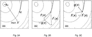
    • Figs. 3A-3C each show a contour plot of a Lyapunov function of a stable dynamics system, in which Fig. 3A illustrates the trajectory of the Lyapunov function, Fig. 3B illustrates (x) having a component g(x) not in the half space and which may be subtracted to obtain f(x), and Fig. 3C illustrates f(x) being in the half space and returned unchanged;
    • Fig. 4A illustrates a rectified linear unit activation function, while Fig. 4B illustrates a smoothed variant of the rectified linear unit activation function;
    • Figs. 5A shows a contour plot of the dynamics of a simple damped pendulum as simulated from first principles, Fig. 5B shows a contour plot of the learned stable dynamics model and Fig. 5C shows a contour plot of the learned Lyapunov function;
    • Fig. 6A shows the prediction error of the angular position and angular velocity for an 8-link pendulum as a function of timesteps, while Fig. 6B shows the average prediction error over 1000 timesteps as a function of a number of links of the pendulum;
    • Fig. 7A shows a structure of a video texture generation network in which the encoder e and decoder d form a Variational Autoencoder, and the stable dynamics model f is trained together with the decoder d to predict a next frame in a video texture;
    • Fig. 7B shows trajectories projected onto a two-dimensional plane for, from left to right, three different runs of the dynamics model with the stability constraint and for a dynamics model without the stability constraint in the form of a generic neural network;
    • Fig. 8 shows system for control or monitoring using learned dynamics model;
    • Fig. 9 shows the system as part of an (semi-)autonomous vehicle; and
    • Fig. 10 shows a computer-readable medium comprising data.
  • It should be noted that the figures are purely diagrammatic and not drawn to scale. In the figures, elements which correspond to elements already described may have the same reference numerals.
  • List of reference numbers
  • The following list of reference numbers is provided for facilitating the interpretation of the drawings and shall not be construed as limiting the claims.
  • 20
    sensor
    22
    camera
    40
    actuator
    42
    electric motor
    60
    environment
    80
    (semi)autonomous vehicle
    100
    system for training dynamics model
    160
    processor subsystem
    180
    data storage interface
    190
    data storage
    192
    training data
    194
    model data
    196
    model data
    200
    method for training dynamics model
    210
    accessing training data
    220
    accessing model data defining dynamics model
    230
    learning dynamics model based on training data
    240
    joint learning of dynamics model with Lyapunov function
    300-304
    contour plot of Lyapunov function of stable dynamics system
    400
    rectified linear unit activation function
    410
    smoothed variant of rectified linear unit activation function
    500
    streamplot of dynamics as simulated from first principles
    510
    streamplot of dynamics of the learned dynamics model
    520
    contour plot of the learned Lyapunov function
    600
    prediction error as a function of timestamp for 8-link pendulum
    610
    timestamp
    620
    prediction error
    630
    average error over 1000 timestamps as function of number of links
    640
    number of links
    650
    average prediction error
    660
    simple learned dynamics model
    670
    stable learned dynamics model
    700
    structure of video texture generation network
    710
    stable dynamics model run 1
    720
    stable dynamics model run 2
    730
    stable dynamics model run 3
    740
    naive dynamics model
    800
    system for control or monitoring using learned dynamics model
    820
    sensor data interface
    822
    sensor data
    840
    actuator interface
    842
    control data
    860
    processor subsystem
    880
    data storage interface
    890
    data storage
    900
    method for control or monitoring using learned dynamics model
    910
    accessing sensor data
    920
    accessing model data defining learned dynamics model
    930
    inferring future state from observed current state using model
    940
    providing output data based on inferred future state
    1000
    computer-readable medium
    1010
    non-transitory data
    DETAILED DESCRIPTION OF EMBODIMENTS
  • The following describes with reference to Figs. 1 and 2 the training of a learnable dynamics model which comprises a learnable Lyapunov function to establish global stability of the learned dynamics model, then describes with reference to Figs. 3A-5C the dynamics model and its training in more detail, then describes with reference to Fig. 6A-7B applications of the dynamics model which include a comparison to a non-stable dynamics model, and with reference to Figs. 8-10 the use of the learned dynamics model for the control or monitoring of a physical system, such as an (semi-)autonomous vehicle.
  • Fig. 1 shows a system 100 for training a dynamics model to learn dynamics of a physical system by learning to infer a future state of the physical system and/or its environment based on a current state of the physical system and/or its environment.
  • The system 100 may comprise an input interface for accessing training data 192 representing a time-series of states of the physical system and/or its environment and for accessing model data 194 defining a machine learnable dynamics model which comprises a machine learnable Lyapunov function. For example, as also illustrated in Fig. 1, the input interface may be constituted by a data storage interface 180 which may access the training data 192 and the model data 194 from a data storage 190. For example, the data storage interface 180 may be a memory interface or a persistent storage interface, e.g., a hard disk or an SSD interface, but also a personal, local or wide area network interface such as a Bluetooth, Zigbee or Wi-Fi interface or an ethernet or fiberoptic interface. The data storage 190 may be an internal data storage of the system 100, such as a hard drive or SSD, but also an external data storage, e.g., a network-accessible data storage. In some embodiments, the training data 192 and the model data 194 may each be accessed from a different data storage, e.g., via a different subsystem of the data storage interface 180. Each subsystem may be of a type as is described above for the data storage interface 180.
  • The system 100 may further comprise a processor subsystem 160 which may be configured to, during operation of the system 100, to learn the dynamics model based on time-sequential pairs of states so as to learn to infer a future state of the physical system and/or its environment based on the current state, wherein said learning is constrained to provide a globally stable modelling of the dynamics of the physical system by jointly learning the dynamics model and the Lyapunov function so that values of the learned Lyapunov function decrease along all trajectories of states inferred by the learned dynamics model. This dynamics model and its training will be further described with reference to Fig. 3A-5C.
  • The system 100 may further comprise an output interface for outputting trained model data 196 representing the learned (or 'trained') dynamics model. For example, as also illustrated in Fig. 1, the output interface may be constituted by the data storage interface 180, with said interface being in these embodiments an input/output ('IO') interface, via which the trained model data 196 may be stored in the data storage 190. For example, the model data 194 defining the 'untrained' dynamics model may during or after the training be replaced, at least in part, by the model data 196 of the trained dynamics model, in that the parameters of the dynamics model, such as weights and other types of parameters of neural networks, may be adapted to reflect the training on the training data 192. This is also illustrated in Fig. 1 by the reference numerals 194, 196 referring to the same data record on the data storage 190. In other embodiments, the trained model data 196 may be stored separately from the model data 194 defining the 'untrained' dynamics model. In some embodiments, the output interface may be separate from the data storage interface 180, but may in general be of a type as described above for the data storage interface 180.
  • Fig. 2 shows a computer-implemented method 200 for training a dynamics model to learn dynamics of a physical system by learning infer a future state of the physical system and/or its environment based on a current state of the physical system and/or its environment. The method 200 may correspond to an operation of the system 100 of Fig. 1, but does not need to, in that it may also correspond to an operation of another type of system, apparatus or device or in that it may correspond to a computer program.
  • The computer-implemented method 200 is shown to comprise, in a step titled "ACCESSING TRAINING DATA", accessing 210 training data representing a time-series of states of the physical system and/or its environment, in a step titled "ACCESSING MODEL DATA DEFINING DYNAMICS MODEL", accessing 220 model data defining a machine learnable dynamics model which comprises a machine learnable Lyapunov function, in a step titled "LEARNING DYNAMICS MODEL BASED ON TRAINING DATA", learning 230 the dynamics model based on time-sequential pairs of states so as to learn to infer a future state of the physical system and/or its environment based on the current state, wherein said learning step 230 comprises, in a step or sub-step titled "JOINT LEARNING OF DYNAMICS MODEL WITH LYAPUNOV FUNCTION", constraining the learning to provide a globally stable modelling of the dynamics of the physical system by jointly learning 240 the dynamics model and the Lyapunov function so that values of the learned Lyapunov function decrease along all trajectories of states inferred by the learned dynamics model.
  • The following examples describe the machine learnable dynamics model, including the training thereof, in more detail. However, the actual implementation of the machine learnable dynamics model and its training may be carried out in various other ways, e.g., on the basis of analogous mathematical concepts. For example, instead of using a neural network, a Gaussian process or another machine learnable model type may be used to learn the nominal dynamics of the physical system and to learn the Lyapunov function.
  • Briefly speaking, the following deals with learning continuous time dynamical systems, but also applies mutatis mutandis to discrete time dynamical systems. That is, given a state at time t, x t R n ,
    Figure imgb0003
    the time-derivative of the state is modelled as x ˙ t d dt x t = f x t
    Figure imgb0004
    for some function f : R n R n .
    Figure imgb0005
    Modeling the time evolution of such dynamical systems (or their counterparts with control inputs (t) = f(x(t), u(t)) for u t R m
    Figure imgb0006
    ) is a foundational problem, with applications in reinforcement learning, control, forecasting, and many other settings. Owing to their representational power, neural networks have long been a natural choice for modeling the above function. However, when using a generic neural network to model dynamics in this setting, very little can be guaranteed about the behavior of the learned system. For example, it is very difficult to say anything about the stability properties of a learned model (informally, the tendency of the system to remain within some invariant bounded set). While some recent work has begun to consider stability properties of neural networks, see the aforementioned [1, 2, 3], such work has typically done so by ("softly") enforcing stability as an additional loss term on the training data. Consequently, such work can say little about the stability of the system in unseen states.
  • In this specification, an approach is described to learning neural network dynamics that are provably stable over the entirety of the state space. To do so, the system dynamics and a Lyapunov function may be jointly learned. This stability may be a hard constraint imposed upon the model. Accordingly, unlike recent approaches, stability may not be enforced via an imposed loss function but built directly into the dynamics of the model (e.g., even a randomly initialized model in the described model class will be provably stable everywhere in state space). For that purpose, a Lyapunov function may be provided, which may be based on an input convex neural network, and which may ensure global exponential stability to an equilibrium point while still allowing for expressive dynamics.
  • Using these methods, the following demonstrates learning the dynamics of physical models such as n-link pendulums, e.g., with reference to Figs. 5A-6B, and shows a substantial improvement over generic networks. It is also shown how such dynamics models can be integrated into larger network systems to learn dynamics over complex output spaces. In particular, it is shown with reference to Figs. 7A-7B how to combine the model with a variational auto-encoder (VAE) to learn dynamic 'video textures'.
  • The following primarily considers the setting of autonomous dynamics (t) = f(x(t)) for x t R n .
    Figure imgb0007
    While the techniques described in this specification are applicable to the dynamics with control as well, the following discussion focuses on the autonomous case for ease of explanation. A system is defined to be globally asymptotically stable (for simplicity, around the equilibrium point x e = 0) if we have x(t) → 0 as t → ∞ for any initial state x 0 R n ;
    Figure imgb0008
    f is locally asymptotically stable if the same holds but only for x(0) ∈ B where B is some bounded set containing the origin. Similarly, f is globally (locally, respectively) exponentially stable (e.g., converges to the equilibrium "exponentially quickly") if x t 2 m x ( 0 2 e αt
    Figure imgb0009
    for some constants m, α ≥ 0 for any x 0 R n
    Figure imgb0010
    (B, respectively).
  • The area of Lyapunov theory establishes the connection between the various types of stability mentioned above and descent according to a particular type of function known as a Lyapunov function. Specifically, let V : R n R
    Figure imgb0011
    be a continuously differentiable positive definite function, i.e., V(x) > 0 for x ≠ 0 and V(0) = 0. Lyapunov analysis says that f is stable (according to the definitions above) if and only if we can find some function V as above such the value of this function is decreasing along trajectories generated by f. Formally, this is the condition that the time derivative (x(t)) < 0, i.e., V ˙ x t = d dt V x t = V x T d dt x t = V x t T f x t < 0
    Figure imgb0012
  • This condition should hold for all x t R n
    Figure imgb0013
    or for all x(t) ∈ B to ensure global or local stability respectively. Similarly, f is globally asymptotically stable if and only if there exists positive definite V such that V ˙ x t αV x t , with c 1 x 2 2 V x c 2 x 2 2 .
    Figure imgb0014
  • Showing that these conditions imply the various forms of stability is relatively straightforward, but showing the converse (that any stable system must obey this property for some V) is relatively more complex. However, we are largely concerned with the "simpler" of these two directions, as the goal is to enforce conditions that ensure stability.
  • Briefly speaking, for an arbitrary (non-stable) nominal dynamics and a given positive definite function V(x) ≥ 0, V(0) = 0, V(x) > 0 for x ≠ 0, we may ensure global asymptotic stability by projecting to f x = Proj f ^ x , f : V x T f αV x = f ^ x V x ReLU V x T f ^ x + αV x V x 2 2
    Figure imgb0015
    where Proj(·,·) denotes the orthogonal projection onto a halfspace. For example, automatic differentiation tools may be used to define/implement V such that including ∇V in the definition of f can be done straightforwardly. Overall, the neural network for f may be trained straightforwardly, similar to the training for any other function.
  • The following provides a more detailed explanation of the above while referring to Figs. 3A-7B. The intuition of at least some of the techniques described in this specification may be summarized as follows: instead of learning a dynamics function and attempting to separately verify its stability via a Lyapunov function, a dynamics model and Lyapunov function are jointly learned, where the modeling of the dynamics may be inherently constrained to be stable (everywhere in the state space) according to the Lyapunov function. Specifically, following the principles mentioned above, let f ^ : R n R n
    Figure imgb0016
    denote a "nominal" dynamics model referring to a dynamics model which is directly learned on the training data, e.g., without incorporating the Lyapunov function, and let V : R n R
    Figure imgb0017
    be a positive definite function: V(x) ≥ 0 for x ≠ 0 and V(0) = 0. Then in order to (provably, globally) ensure that a dynamics function is stable, may be projected such that it satisfies the condition V x T f ^ x αV x
    Figure imgb0018
    i.e., one may define the dynamics as f x = Proj f ^ x , f : V x T f αV x = { f ^ x if V x T f ^ x αV x f ^ x V x V x T f ^ x + αV x V x 2 2 otherwise = f ^ x V x ReLU V x T f ^ x + αV x V x 2 2
    Figure imgb0019
    where Proj(x; C) may denote the orthogonal projection of x onto the point C, and where the second equation follows from the analytical projection of a point onto a halfspace. V may for example be defined using automatic differentiation tools. Accordingly, the gradient ∇V term may be included into the definition of f, obtaining a composite neural network for f (e.g., comprising a first neural network for and a second neural network for the Lyapunov function) which may be trained just like any other function.
  • Figs. 3A-3C provide an illustration of the above. Each of Figs. 3A-3C shows a contour plot 300-304 of a Lyapunov function of a stable dynamics system, in which Fig. 3A illustrates the trajectory of the Lyapunov function by way of an arrow pointing in a direction of increasing value of the Lyapunov function. Let g(x) = V x V x 2 2 ReLU V x T f ^ x + αV x .
    Figure imgb0020
    Fig. 3B illustrates (x) having a component g(x) not in the half space and which may be subtracted to obtain f(x), and Fig. 3C illustrates (x) being in the half space and returned unchanged.
  • As indicated previously, V may need to be positive definite, but additionally V may be preferred to have no local optima except 0. This is due to Lyapunov decrease condition: one may desire to guarantee stability to the equilibrium point x = 0, yet the decrease condition imposed upon the dynamics may mean that V may be decreasing along trajectories of f. If V has a local optimum away from the origin, the dynamics may in theory, but may not need to in practice, get stuck in this location; this may manifest itself by the V x 2 2
    Figure imgb0021
    term going to zero, which may result in the dynamics becoming undefined at the optima. The above conditions may be enforced by design decisions as described below.
  • The Lyapunov function V may be learned and represented by a neural network. To ensure the required properties of V, the following considerations may apply. More specifically, one may prefer to ensure (i) that V has only one (global) optimum (without loss of generality assumed to be V(0) = 0), (ii) that V is positive definite, e.g., V(x) > 0 for x ≠ 0 and (iii) that V is continuously differentiable.
  • Firstly, property (i) may be enforced by representing V with an input-convex neural network (ICNN) g, which may be defined by: z 1 = σ 0 W 0 x + b 0 z i + 1 = σ i U i z i + W i x + b i , i = 1 , , k 1 g x z k
    Figure imgb0022
    where Wi may be real-valued weights mapping from inputs to the i + 1 layer activations; Ui may be positive weights mapping previously layer activations zi to the next layer; bi may be real-valued biases; and σi may be convex, monotonically non-decreasing non-linear activations, such as the ReLU or smooth variants thereof. With this formulation, g is convex in x, and any convex function can be approximated by such networks.
  • Secondly, it may be desirable to ensure that V is positive definite. Representing V with an ICNN makes V convex, i.e., there is only one optimum, however it does not enforce V(0) = 0. There are multiple ways to ensure V(0) = 0. For example, one could find the global optimum of g and shift it or by removing the biases terms. However, shifting requires finding the optimum during training, which may be computationally expensive while removing the biases may put limitations on the class of variables that can be approximated. As an alternative approach, g may be shifted to ensure V(0) = 0, while a little quadratic regularization term may be added to ensure positive definiteness, e.g., as: V x = σ k + 1 g x g 0 + ϵ x 2 2
    Figure imgb0023
    where σk may be a positive, convex, non-decreasing function with σk (0) = 0 and ε is a small constant, for example selected such that ε > mg x x / 2.
    Figure imgb0024
  • Thirdly, it may be desirable to ensure that V is continuously differentiable, for example by using a smoothed version 410 of the ReLU activations, as shown in Fig. 4B, that replaces the linear ReLU 400, as shown in Fig. 4A, by a quadratic function in [0, d]. σ x = { 0 if x 0 / 2 d x 2 if 0 < x < d x / 2 d otherwise .
    Figure imgb0025
  • Additionally, warping to the input space may be used, such that the input to g is first mapped by any continuously differentiable, invertible function. Namely, although convexity may ensure that the Lyapunov function have no local optima, this may be a sufficient but not necessary condition, and indeed requiring a strongly convex Lyapunov function may impose too strict a requirement upon the learned dynamics. For this reason, the input to the ICNN function g(x) above may be optionally preceded by any continuously differentiable invertible function F : R n × R n ,
    Figure imgb0026
    e.g., using V x = σ κ + 1 g F x g F 0 + ϵ x 2 2 .
    Figure imgb0027
    as the Lyapunov function. Invertibility may ensure that the sublevel sets of V (which are convex sets, by definition) may map to contiguous regions of the composite function gF, thus ensuring that no local optima exist in this composed function.
  • The above-described dynamics model may be demonstrated on several example problems described with reference to Figs. 5A-7B. Figs. 5A-5C relate to the modelling of a physically-based dynamical system, specifically the n-link pendulum. A damped, rigid n-link pendulum's state x may be described by the angular position θi and angular velocity θ̇i of each link i. In the following, may be a 2n-100-100-2n fully connected neural network, and V a 2n-60-60-1 ICNN, with properties described previously. The models are trained with pairs of data (x, ) produced by the symbolic algebra solver sympy.
  • In Fig. 5A, the simulated dynamics for the case of a simple damped pendulum (i.e., with n = 1) are shown by a streamplot 500, while Fig. 5B shows a streamplot 510 corresponding to the dynamics learned by the dynamics model and with Fig. 5C showing a contour plot 520 of the learned Lyapunov function. As can be seen, the dynamics may be learned to accurately predict motion of the pendulum even over long time periods.
  • The learned dynamics may also be evaluated quantitatively while varying n and the time horizon of simulation. Fig. 6A shows a graph 600 showing the prediction error 620 of the angular position θ and angular velocity θ̇ for an 8-link pendulum as a function of timesteps 610, while Fig. 6B shows a graph 630 showing the average prediction error 650 over 1000 timesteps as a function of a number of links 640 of the pendulum. Both graphs 600, 630 show the errors for both a 'simple' prior art model 660 and a learned dynamics model 670 of a type as described in this specification. While both the simple and the stable models show increasing mean error at the start of the trajectory, the dynamics model 670 is able to capture the contraction in the physical system (implied by conservation of energy) and in fact exhibits decreasing error towards the end of the simulation (true and simulated dynamics are both stable). In comparison, the error in the simple model increases.
  • Figs. 7A-7B relate to another example in which the dynamics model as described in this specification may be used for stable video texture generation, for example using a Variational Autoencoder (VAE) to learn an encoding for images and the stable dynamics model to learn the dynamics in encoding-space. Given a sequence of frames (y 0, y 1,...), the overall network may be fed a frame at time t and may be trained to reconstruct the frames at time t and t + 1. Specifically, a VAE may be defined by the encoder e : Y R 2 n
    Figure imgb0028
    giving mean and variance µ, log σ t 2 = e y t ,
    Figure imgb0029
    latent state z t R n N µ t σ t 2
    Figure imgb0030
    and decoder d : R n Y , y t d z t .
    Figure imgb0031
    The overall network may be trained to minimize both the standard VAE loss (reconstruction error plus a KL divergence term), but also to minimize the reconstruction loss of a next predicted state. The evolution of the latent dynamics may be modeled at z t+1f(zt ), or more precisely y t+1d(f(zt )). In other words, as also illustrated in Fig. 7A which shows a structure of the video texture generation network in which the encoder e and decoder d form a Variational Autoencoder and in which the stable dynamics model f is trained together with the decoder d to predict a next frame in a video texture, the overall network may be trained minimize: minimize e , d , f ^ , V t = 1 T 1 KL N µ t , σ t 2 I N 0 I + E z d z t y t 2 2 + d f z t y t + 1 2 2
    Figure imgb0032
  • The overall network may be trained on pairs of successive frames sampled from videos. To generate video textures, the dynamics model may be seeded with the encoding of a single frame and the dynamics model may be numerically integrated to obtain a trajectory. The VAE decoder may convert each step of the trajectory into a frame.
  • Fig. 7B shows trajectories projected onto a two-dimensional plane for, from left to right, three different runs of the dynamics model with the stability constraint and for a dynamics model without the stability constraint in the form of a generic neural network. In this example, the true latent space is 320-dimensional, and the trajectories may be projected onto a two-dimensional plane for display. For the non-stable model, the dynamics quickly diverge and produce a static image, whereas for the stable model, it is possible to generate different (stable) trajectories that keep generating realistic images over long time horizons.
  • Fig. 8 shows a system 800 for controlling or monitoring a physical system using a machine learned modelling of dynamics of the physical system. The system 800 may comprise an input interface 880 for accessing trained model data 196 representing a learned dynamics model as may be generated by the system 100 of Fig. 1 or the method 200 of Fig. 2 or as described elsewhere. For example, as also illustrated in Fig. 8, the input interface may be constituted by a data storage interface 880 which may access the trained model data 196 from a data storage 890. In general, the input interface 880 and the data storage 890 may be of a same type as described with reference to Fig. 1 for the input interface 180 and the data storage 190. Fig. 8 further shows the data storage 892 comprising sensor data 822 representing an observation of a current state of the physical system. As described elsewhere, in some embodiments, the sensor data 822 may also be received directly from a sensor 20 via a sensor interface 820 of via another type of interface instead of being accessed from the data storage 890 via the data storage interface 880.
  • The system 800 may further comprise a processor subsystem 860 which may be configured to, during operation of the system 800, infer the future state of the physical system based on the observation of the current state of the physical system as obtained from the sensor data 822, and using an output interface as described elsewhere, provide output data 842 to an output device to enable the control or monitoring of the physical system based on the inferred future state, as also described elsewhere in this specification.
  • It will be appreciated that the same considerations and implementation options apply for the processor subsystem 860 as for the processor subsystem 860 of Fig. 1. It will be further appreciated that the same considerations and implementation options may in general apply to the system 800 as for the system 100 of Fig. 1, unless otherwise noted.
  • Fig. 8 further shows various optional components of the system 800. For example, in some embodiments, the system 800 may comprise a sensor data interface 820 for directly accessing sensor data 822 acquired by a sensor 20 in an environment 60. The sensor 20 may but does not need to be part of the system 800. The sensor 20 may have any suitable form, such as an image sensor, a lidar sensor, a radar sensor, a pressure sensor, a contain temperature sensor, etc. In some embodiments, the sensor data 822 may sensor measurements of different physical quantities in that it may be obtained from two or more different sensors sensing different physical quantities. The sensor data interface 820 may have any suitable form corresponding in type to the type of sensor, including but not limited to a low-level communication interface, e.g., based on I2C or SPI data communication, or a data storage interface of a type as described above for the data storage interface 880.
  • In some embodiments, the system 800 may comprise an actuator interface 840 for providing control data 842 to an actuator 40 in the environment 60. Such control data 842 may be generated by the processor subsystem 860 to control the actuator 40 based on one or more inferred future states of the physical system, which may be generated using the learned dynamics model. For example, the actuator may be an electric, hydraulic, pneumatic, thermal, magnetic and/or mechanical actuator. Specific yet non-limiting examples include electrical motors, electroactive polymers, hydraulic cylinders, piezoelectric actuators, pneumatic actuators, servomechanisms, solenoids, stepper motors, etc. Such type of control is described with reference to Fig. 9 for an (semi-)autonomous vehicle.
  • In other embodiments (not shown in Fig. 8), the system 800 may comprise an output interface to a rendering device, such as a display, a light source, a loudspeaker, a vibration motor, etc., which may be used to generate a sensory perceptible output signal which may be generated based on one or more inferred future states of the physical system. The sensory perceptible output signal may be directly indicative of the inferred future states of the physical system, but may also represent a derived sensory perceptible output signal, e.g., for use in guidance, navigation or other type of control of the physical system.
  • In general, each system described in this specification, including but not limited to the system 100 of Fig. 1 and the system 800 of Fig. 8, may be embodied as, or in, a single device or apparatus, such as a workstation or a server. The device may be an embedded device. The device or apparatus may comprise one or more microprocessors which execute appropriate software. For example, the processor subsystem of the respective system may be embodied by a single Central Processing Unit (CPU), but also by a combination or system of such CPUs and/or other types of processing units. The software may have been downloaded and/or stored in a corresponding memory, e.g., a volatile memory such as RAM or a non-volatile memory such as Flash. Alternatively, the processor subsystem of the respective system may be implemented in the device or apparatus in the form of programmable logic, e.g., as a Field-Programmable Gate Array (FPGA). In general, each functional unit of the respective system may be implemented in the form of a circuit. The respective system may also be implemented in a distributed manner, e.g., involving different devices or apparatuses, such as distributed local or cloud-based servers. In some embodiments, the system 800 may be part of vehicle, robot or similar physical entity, and/or may be represent a control system configured to control the physical entity.
  • Fig. 9 shows an example of the above, in that the system 800 is shown to be a control system of an (semi-)autonomous vehicle 80 operating in an environment 60. The autonomous vehicle 80 may be autonomous in that it may comprise an autonomous driving system or a driving assistant system, with the latter also being referred to as a semiautonomous system. The autonomous vehicle 80 may for example incorporate the system 800 to control the steering and the braking of the autonomous vehicle based on sensor data obtained from a video camera 22 integrated into the vehicle 80. For example, the system 800 may control an electric motor 42 to perform (regenerative) braking in case the autonomous vehicle 80 is expected to collide with a traffic participant. The system 800 may control the steering and/or braking to avoid collision with the traffic participant. For that purpose, the system 800 may infer a future state of the vehicle with respect its environment, including the traffic participant, based on the sensor data obtained from the video camera. If the future state of the vehicle, e.g., its future position relative to the traffic participant, is expected to result in a collision, the system 800 may take corresponding action.
  • Fig. 10 shows a computer-implemented method 900 for controlling or monitoring a physical system using a machine learned modelling of dynamics of the physical system. The method 900 may correspond to an operation of the system 800 of Fig. 8, but may alternatively also be performed using or by any other system, apparatus or device.
  • The method 900 is shown to comprise, in a step titled "ACCESSING SENSOR DATA", accessing 910 sensor data representing an observation of a current state of the physical system, in a step titled "ACCESSING MODEL DATA DEFINING LEARNED DYNAMICS MODEL", accessing 920 model data defining a machine learned dynamics model as described elsewhere in this specification, e.g., as obtained from the system 100 or method 200 of Figs. 1-2, in a step titled "INFERRING FUTURE STATE FROM OBSERVED CURRENT STATE USING MODEL", inferring 930 the future state of the physical system based on the observation of the current state of the physical system as obtained from the sensor data, and in a step titled "PROVIDING OUTPUT DATA BASED ON INFERRED FUTURE STATE", using an output interface to an output device which is used in the control or monitoring of the physical system, providing 940 output data to the output device to enable the control or monitoring of the physical system based on said inferred future state.
  • It will be appreciated that, in general, the operations or steps of the computer-implemented methods 200 and 800 of respectively Figs. 2 and 10 may be performed in any suitable order, e.g., consecutively, simultaneously, or a combination thereof, subject to, where applicable, a particular order being necessitated, e.g., by input/output relations.
  • Each method, algorithm or pseudo-code described in this specification may be implemented on a computer as a computer implemented method, as dedicated hardware, or as a combination of both. As also illustrated in Fig. 11 , instructions for the computer, e.g., executable code, may be stored on a computer readable medium 1000, e.g., in the form of a series 1010 of machine-readable physical marks and/or as a series of elements having different electrical, e.g., magnetic, or optical properties or values. The executable code may be stored in a transitory or non-transitory manner. Examples of computer readable mediums include memory devices, optical storage devices, integrated circuits, servers, online software, etc. Fig. 11 shows an optical disc 1010. In an alternative embodiment, the computer readable medium 1000 may comprise trained model data 1010 defining a machine learned dynamics model as described elsewhere in this specification.
  • Examples, embodiments or optional features, whether indicated as non-limiting or not, are not to be understood as limiting the invention as claimed.
  • In accordance with an abstract of the specification, a system and computer-implemented method are provided for training a dynamics model to learn the dynamics of a physical system. In particular, the dynamics model may be learned to be able to infer a future state of the physical system and/or its environment based on a current state of the physical system and/or its environment. The learned dynamics model is inherently globally stable. Namely, instead of learning a dynamics model and attempting to separately verify its stability, the learnable dynamics model comprises a learnable Lyapunov function which is jointly learned together with the nominal dynamics of the physical system. Accordingly, the learned dynamics model is highly suitable for real-life applications in which a physical system may assume a state which was unseen during training as the learned dynamics model is inherently globally stable.
  • It should be noted that the above-mentioned embodiments illustrate rather than limit the invention, and that those skilled in the art will be able to design many alternative embodiments without departing from the scope of the appended claims. In the claims, any reference signs placed between parentheses shall not be construed as limiting the claim. Use of the verb "comprise" and its conjugations does not exclude the presence of elements or stages other than those stated in a claim. The article "a" or "an" preceding an element does not exclude the presence of a plurality of such elements. Expressions such as "at least one of" when preceding a list or group of elements represent a selection of all or of any subset of elements from the list or group. For example, the expression, "at least one of A, B, and C" should be understood as including only A, only B, only C, both A and B, both A and C, both B and C, or all of A, B, and C. The invention may be implemented by means of hardware comprising several distinct elements, and by means of a suitably programmed computer. In the device claim enumerating several means, several of these means may be embodied by one and the same item of hardware. The mere fact that certain measures are recited in mutually different dependent claims does not indicate that a combination of these measures cannot be used to advantage.

Claims (15)

  1. A machine learning system (100) for training a dynamics model to learn dynamics of a physical system by learning to infer a future state of the physical system and/or its environment based on a current state of the physical system and/or its environment, the machine learning system comprising:
    - an input interface (180) for accessing:
    - training data (192) representing a time-series of states (xt ) of the physical system and/or its environment;
    - model data (194) defining a machine learnable dynamics model (f(xt )) which comprises a machine learnable Lyapunov function (V(xt ));
    - a processor subsystem (160) configured to learn the dynamics model based on time-sequential pairs of states (xt ) so as to learn to infer a future state (x t+1 = f(xt )) of the physical system and/or its environment based on the current state (xt ), wherein said learning is constrained to provide a globally stable modelling of the dynamics of the physical system by jointly learning the dynamics model and the Lyapunov function so that values of the learned Lyapunov function decrease (V(x t+1) < V(xt )) along all trajectories of states (x 0, x 1, ...,xT ) inferred by the learned dynamics model.
  2. The machine learning system (100) according to claim 1, wherein the processor subsystem (160) is configured to jointly learn the dynamics model and the Lyapunov function by learning as the dynamics model (f(xt )) a projection (Proj) of nominal dynamics ((xt )) of the physical system, which are learned based on the time-series of states (xt ), onto a function that fulfills the Lyapunov condition as defined by the Lyapunov function (V(xt )).
  3. The machine learning system (100) according to claim 2, wherein the projection (Proj) is an orthogonal projection onto a halfspace.
  4. The machine learning system (100) according to claim 2 or 3, wherein the dynamics model (f(xt )) comprises a neural network for learning the nominal dynamics ((xt )) of the physical system based on the time-sequential pairs of states (xt ).
  5. The machine learning system (100) according to any one of claims 1 to 4, wherein the machine learnable Lyapunov function (V(xt )) is represented at least in part by an input-convex neural network (ICNN, g(x)).
  6. The machine learning system (100) according to claim 5, wherein the input-convex neural network (ICNN, g(x)) comprises a smoothed variant of a rectified linear unit (ReLu) for each of the activation functions.
  7. The machine learning system (100) according to claim 5 or 6, wherein the Lyapunov function (V(xt )) is shifted to establish a zero value of the Lyapunov function (V(xt ) = 0) at an equilibrium point (xt = 0) of the Lyapunov function, and wherein the learning of the Lyapunov function comprises using a quadratic regularization term to ensure strict positive definitiveness of the Lyapunov function.
  8. The machine learning system (100) according to any one of claims 5 to 7, wherein the processor subsystem (160) is configured to, when learning the input-convex neural network (ICNN, g(x)) on the training data (xt ), apply a continuously differentiable invertible function (F(x)) to the training data (xt ) and use an output of the continuously differential invertible function as an input (g(F(x)) to the input-convex neural network.
  9. A computer-readable medium (1000) comprising transitory or non-transitory model data (1010) defining a machine learnable dynamics model (f(xt )) which comprises a machine learnable Lyapunov function (V(xt )), wherein the dynamics model is learned to infer a future state (x t+1 = f(xt )) of the physical system and/or its environment based on the current state (xt ), wherein said learning of the dynamics model has been constrained to provide a globally stable modelling of the dynamics of the physical system by the dynamics model and the Lyapunov function having been jointly learned so that values of the learned Lyapunov function decrease (V(x t+1) < V(xt )) along all trajectories of states (x 0, x 1, ..., xT ) inferred by the learned dynamics model.
  10. A computer-implemented method (200) for training a dynamics model to learn dynamics of a physical system by learning infer a future state of the physical system and/or its environment based on a current state of the physical system and/or its environment, the method comprising:
    - accessing (210, 220):
    - training data representing a time-series of states (xt ) of the physical system and/or its environment;
    - model data defining a machine learnable dynamics model (f(xt ) which comprises a machine learnable Lyapunov function (V(xt ));
    - learning (230) the dynamics model based on time-sequential pairs of states (xt ) so as to learn to infer a future state (x t+1 = f(xt )) of the physical system and/or its environment based on the current state (xt ), wherein said learning comprises:
    - constraining the learning to provide a globally stable modelling of the dynamics of the physical system by jointly learning (240) the dynamics model and the Lyapunov function so that values of the learned Lyapunov function decrease (V(x t+1) < V(xt )) along all trajectories of states (x 0, x 1, ..., xT ) inferred by the learned dynamics model.
  11. A computer-implemented method (900) for controlling or monitoring a physical system using a machine learned modelling of dynamics of the physical system, the method comprising:
    - accessing (910, 920):
    - sensor data representing an observation of a current state (xt ) of the physical system;
    - model data defining a machine learned dynamics model (f(xt )) which comprises a machine learnable Lyapunov function (V(xt )), wherein the dynamics model is learned to infer a future state (x t+1 = f(xt )) of the physical system and/or its environment based on the current state (xt ), wherein said learning of the dynamics model has been constrained to provide a globally stable modelling of the dynamics of the physical system by the dynamics model and the Lyapunov function having been jointly learned so that values of the learned Lyapunov function decrease (V(x t+1) < V(xt )) along all trajectories of states (x 0, x 1, ..., x T ) inferred by the learned dynamics model;
    - inferring (930) the future state (x t+1) of the physical system based on the observation of the current state of the physical system as obtained from the sensor data;
    - using an output interface to an output device which is used in the control or monitoring of the physical system, providing (940) output data to the output device to enable the control or monitoring of the physical system based on said inferred future state.
  12. A computer-readable medium (1000) comprising transitory or non-transitory data (1010) representing instructions arranged to cause a processor system to perform the computer-implemented method according to claim 10 or 11.
  13. A control or monitoring system (800) for controlling or monitoring a physical system using a machine learned modelling of dynamics of the physical system, the control or monitoring system comprising:
    - an input interface (820, 880) for accessing:
    - sensor data (822) representing an observation of a current state (xt ) of the physical system;
    - model data (196) defining a machine learned dynamics model (f(xt )) which comprises a machine learnable Lyapunov function (V(xt )), wherein the dynamics model is learned to infer a future state (x t+1 = f(xt )) of the physical system and/or its environment based on the current state (xt ), wherein said learning of the dynamics model has been constrained to provide a globally stable modelling of the dynamics of the physical system by the dynamics model and the Lyapunov function having been jointly learned so that values of the learned Lyapunov function decrease (V(x t+1) < V(xt )) along all trajectories of states (x 0, x 1, ..., xT ) inferred by the learned dynamics model;
    - an output interface (840) to an output device (40, 42) which is used in the control or monitoring of the physical system;
    - a processor subsystem (860) configured to:
    - infer the future state (x t+1) of the physical system based on the observation of the current state of the physical system as obtained from the sensor data;
    - using the output interface, provide output data (842) to the output device to enable the control or monitoring of the physical system based on said inferred future state.
  14. The control or monitoring system (800) according to claim 13, wherein the output device is an actuator (40, 42) associated with the physical system, and wherein the processor subsystem (860) is configured to control the physical system by providing control data (842) to the actuator which is based on the inferred future state (x t+1) of the physical system.
  15. The control or monitoring system (800) according to claim 14, wherein the system is one of:
    - a vehicle control system;
    - a robotics control system;
    - a manufacturing control system; and
    - a building control system.
EP19190105.7A 2019-08-05 2019-08-05 Dynamics model for globally stable modeling of system dynamics Pending EP3772707A1 (en)

Priority Applications (3)

Application Number Priority Date Filing Date Title
EP19190105.7A EP3772707A1 (en) 2019-08-05 2019-08-05 Dynamics model for globally stable modeling of system dynamics
US16/933,245 US11886782B2 (en) 2019-08-05 2020-07-20 Dynamics model for globally stable modeling of system dynamics
CN202010771556.6A CN112327612A (en) 2019-08-05 2020-08-04 Dynamics model for global stable modeling of system dynamics

Applications Claiming Priority (1)

Application Number Priority Date Filing Date Title
EP19190105.7A EP3772707A1 (en) 2019-08-05 2019-08-05 Dynamics model for globally stable modeling of system dynamics

Publications (1)

Publication Number Publication Date
EP3772707A1 true EP3772707A1 (en) 2021-02-10

Family

ID=67551088

Family Applications (1)

Application Number Title Priority Date Filing Date
EP19190105.7A Pending EP3772707A1 (en) 2019-08-05 2019-08-05 Dynamics model for globally stable modeling of system dynamics

Country Status (3)

Country Link
US (1) US11886782B2 (en)
EP (1) EP3772707A1 (en)
CN (1) CN112327612A (en)

Families Citing this family (1)

* Cited by examiner, † Cited by third party
Publication number Priority date Publication date Assignee Title
CN114035594B (en) * 2021-10-11 2023-06-20 广州大学 Method and device for controlling aircraft subject to class clearance lag and output constraints

Family Cites Families (1)

* Cited by examiner, † Cited by third party
Publication number Priority date Publication date Assignee Title
US11049010B2 (en) * 2016-07-26 2021-06-29 The University Of Connecticut Early prediction of an intention of a user's actions

Non-Patent Citations (6)

* Cited by examiner, † Cited by third party
Title
ANDREW J TAYLORVICTOR D DOROBANTUHOANG M LEYISONG YUEAARON D AMES: "Episodic learning with control lyapunov functions for uncertain robotic systems", ARXIV PREPRINT, Retrieved from the Internet <URL:https://arxiv.org/abs/1903.01577>
BRANDON AMOS ET AL: "Input Convex Neural Networks", 14 June 2017 (2017-06-14), arXiv.org, pages 1 - 15, XP055665528, Retrieved from the Internet <URL:https://arxiv.org/abs/1609.07152> [retrieved on 20200205] *
DONG CHENXI ET AL: "The Feature Representation Ability of Variational AutoEncoder", 2018 IEEE THIRD INTERNATIONAL CONFERENCE ON DATA SCIENCE IN CYBERSPACE (DSC), IEEE, 18 June 2018 (2018-06-18), pages 680 - 684, XP033375428, DOI: 10.1109/DSC.2018.00108 *
SPENCER M RICHARDSFELIX BERKENKAMPANDREAS KRAUSE: "The lyapunov neural network: Adaptive stability certification for safe learning of dynamic systems", ARXIV PREPRINT, Retrieved from the Internet <URL:https://arxiv.org/abs/1808.00924>
YINLAM CHOWOFIR NACHUMEDGAR DUENEZ-GUZMANMOHAMMAD GHAVAMZADEH: "A lyapunov-based approach to safe reinforcement learning", NIPS, 2018, Retrieved from the Internet <URL:https://arxiv.org/abs/1805.07708>
ZHE WU ET AL: "Machine learning-based predictive control of nonlinear processes. Part I: Theory", AICHE JOURNAL, vol. 65, no. 11, 4 August 2019 (2019-08-04), US, XP055665512, ISSN: 0001-1541, DOI: 10.1002/aic.16729 *

Also Published As

Publication number Publication date
US11886782B2 (en) 2024-01-30
US20210042457A1 (en) 2021-02-11
CN112327612A (en) 2021-02-05

Similar Documents

Publication Publication Date Title
EP3319016A1 (en) Control systems using deep reinforcement learning
EP3705953B1 (en) Control of a physical system based on inferred state
El-Shamouty et al. Towards safe human-robot collaboration using deep reinforcement learning
EP3722894B1 (en) Control and monitoring of physical system based on trained bayesian neural network
US20210019621A1 (en) Training and data synthesis and probability inference using nonlinear conditional normalizing flow model
US20210394784A1 (en) Making time-series predictions using a trained decoder model
CN115812180A (en) Robot-controlled offline learning using reward prediction model
US20210192347A1 (en) Method for Determining Continuous Information on an Expected Trajectory of an Object
CN112465147A (en) Random data enhancement for machine learning
JP2022542053A (en) Systems and methods for effecting safe stop release of autonomous vehicles
US11886782B2 (en) Dynamics model for globally stable modeling of system dynamics
Yang et al. Safe perception-based control under stochastic sensor uncertainty using conformal prediction
KR20220004933A (en) An image classifier comprising a non-injective transformation
CN112749617A (en) Determining output signals by aggregating parent instances
US20220036181A1 (en) System and method for training a neural ode network
US11868887B2 (en) Making time-series predictions of a computer-controlled system
US11804034B2 (en) Training a function to respond predictably to differences
Agarwal et al. Synthesizing adversarial visual scenarios for model-based robotic control
CN114358241A (en) Method for determining safety-critical output values, and corresponding system and program product
US20230306234A1 (en) Method for assessing model uncertainties with the aid of a neural network and an architecture of the neural network
US20230384762A1 (en) System and Method for Indirect Data-Driven Control Under Constraints
JP7286091B2 (en) Estimation system, estimation device and estimation method
US20220237433A1 (en) Data driven recognition of anomalies and continuation of sensor data
US20240020535A1 (en) Method for estimating model uncertainties with the aid of a neural network and an architecture of the neural network
Baumeister et al. Combining analytical and learned models for model predictive control

Legal Events

Date Code Title Description
PUAI Public reference made under article 153(3) epc to a published international application that has entered the european phase

Free format text: ORIGINAL CODE: 0009012

STAA Information on the status of an ep patent application or granted ep patent

Free format text: STATUS: THE APPLICATION HAS BEEN PUBLISHED

AK Designated contracting states

Kind code of ref document: A1

Designated state(s): AL AT BE BG CH CY CZ DE DK EE ES FI FR GB GR HR HU IE IS IT LI LT LU LV MC MK MT NL NO PL PT RO RS SE SI SK SM TR

AX Request for extension of the european patent

Extension state: BA ME

STAA Information on the status of an ep patent application or granted ep patent

Free format text: STATUS: REQUEST FOR EXAMINATION WAS MADE

17P Request for examination filed

Effective date: 20210810

RBV Designated contracting states (corrected)

Designated state(s): AL AT BE BG CH CY CZ DE DK EE ES FI FR GB GR HR HU IE IS IT LI LT LU LV MC MK MT NL NO PL PT RO RS SE SI SK SM TR

STAA Information on the status of an ep patent application or granted ep patent

Free format text: STATUS: EXAMINATION IS IN PROGRESS

17Q First examination report despatched

Effective date: 20230526