EP3772663B1 - A system for detecting plastics, macro-plastics, micro-plastics and nano-plastics in a maritime, estuary or river environment - Google Patents
A system for detecting plastics, macro-plastics, micro-plastics and nano-plastics in a maritime, estuary or river environment Download PDFInfo
- Publication number
- EP3772663B1 EP3772663B1 EP19191043.9A EP19191043A EP3772663B1 EP 3772663 B1 EP3772663 B1 EP 3772663B1 EP 19191043 A EP19191043 A EP 19191043A EP 3772663 B1 EP3772663 B1 EP 3772663B1
- Authority
- EP
- European Patent Office
- Prior art keywords
- plastics
- detection
- micro
- macro
- nano
- Prior art date
- Legal status (The legal status is an assumption and is not a legal conclusion. Google has not performed a legal analysis and makes no representation as to the accuracy of the status listed.)
- Active
Links
Images


Classifications
-
- G—PHYSICS
- G01—MEASURING; TESTING
- G01S—RADIO DIRECTION-FINDING; RADIO NAVIGATION; DETERMINING DISTANCE OR VELOCITY BY USE OF RADIO WAVES; LOCATING OR PRESENCE-DETECTING BY USE OF THE REFLECTION OR RERADIATION OF RADIO WAVES; ANALOGOUS ARRANGEMENTS USING OTHER WAVES
- G01S13/00—Systems using the reflection or reradiation of radio waves, e.g. radar systems; Analogous systems using reflection or reradiation of waves whose nature or wavelength is irrelevant or unspecified
- G01S13/86—Combinations of radar systems with non-radar systems, e.g. sonar, direction finder
- G01S13/865—Combination of radar systems with lidar systems
-
- G—PHYSICS
- G01—MEASURING; TESTING
- G01S—RADIO DIRECTION-FINDING; RADIO NAVIGATION; DETERMINING DISTANCE OR VELOCITY BY USE OF RADIO WAVES; LOCATING OR PRESENCE-DETECTING BY USE OF THE REFLECTION OR RERADIATION OF RADIO WAVES; ANALOGOUS ARRANGEMENTS USING OTHER WAVES
- G01S15/00—Systems using the reflection or reradiation of acoustic waves, e.g. sonar systems
- G01S15/86—Combinations of sonar systems with lidar systems; Combinations of sonar systems with systems not using wave reflection
-
- G—PHYSICS
- G01—MEASURING; TESTING
- G01S—RADIO DIRECTION-FINDING; RADIO NAVIGATION; DETERMINING DISTANCE OR VELOCITY BY USE OF RADIO WAVES; LOCATING OR PRESENCE-DETECTING BY USE OF THE REFLECTION OR RERADIATION OF RADIO WAVES; ANALOGOUS ARRANGEMENTS USING OTHER WAVES
- G01S17/00—Systems using the reflection or reradiation of electromagnetic waves other than radio waves, e.g. lidar systems
- G01S17/88—Lidar systems specially adapted for specific applications
- G01S17/89—Lidar systems specially adapted for specific applications for mapping or imaging
Definitions
- the present invention relates to the field of detection and classification of floating plastics, macro-plastics, micro-plastics and nano-plastics in water.
- Document US 2005/007448 A1 relates to a remote 3-D imaging system which uses an illumination source to establish the relationship of the image features to the system, which is displayed by virtue of calculations.
- Document EP 2 866 052 A1 relates to a system for monitoring a maritime environment.
- the system includes a plurality of detection devices for detecting objects in the maritime environment according to different object detection schemes.
- a processor determines locations of the objects upon the basis of received detection signals.
- Document US 2013/070556 A1 relates to an aircraft location system for locating aircraft in water environments.
- the system comprises an aircraft structure and a number of acoustic reflectors associated with the aircraft structure.
- the number of acoustic reflectors generate first sound signals in response to receiving second sound signals.
- the invention is based on the finding that different detection wavelengths may be used for detecting the plastics, the macro-plastics, the micro-plastics and the nano-plastics in the maritime, estuary or river environment. Due to different characteristics of plastics, macro-plastics, micro-plastics and nano-plastics at different detection wavelengths, a detection and/or classification of the different plastics may be achieved with increased accuracy.
- the nano-plastics may be formed by very small fibers, the micro-plastics may be formed by small fibers, and the macro-plastics may be formed by larger plastic objects.
- the macro-plastics, the micro-plastics, and the nano-plastics may be dispensed within the water.
- the plastics may refer to larger plastic objects, and may float on the water.
- the invention relates to a system for detecting plastics, macro-plastics, micro-plastics and nano-plastics in a maritime, estuary or river environment.
- the system comprises a plurality of detection devices for detecting the plastics, the macro-plastics, the micro-plastics and the nano-plastics in the environment, the detection devices being configured for detection using different detection wavelengths.
- the system further comprises a data processing device, comprising a communication interface and a processor.
- the communication interface is configured to receive detection signals from the plurality of detection devices.
- the processor is configured to determine locations of the plastics, the macro-plastics, the micro-plastics and the nano-plastics in the environment upon the basis of the received detection signals within a common coordinate system.
- the different detection wavelengths are used for evaluating elastic and/or non-elastic scattering of visible and/or invisible light
- the processor is configured to perform at least one data processing method, in particular a real time processing method and/or an artificial intelligence processing method
- the plurality of detection devices comprise micro-integrated electronics, laser diodes, fiber-optics for light piping and/or a distributed components layout.
- the system is configured to provide information on plastics, macro-plastics, micro-plastics and nano-plastics spatial distribution within the environment using spatial mapping through the use of scanning and/or spatial measurements and/or temporal measurements with in-situ observation feeds into circulation models, and wherein the processor is configured to validate satellite observations.
- the system is configured to use as one of the plurality of detection devices, a multispectral laser/light detection and ranging device (Ladar or Lidar) for selective plastic detection and plastic type classification.
- a multispectral laser/light detection and ranging device Laser or Lidar
- the system is configured to use multiple simultaneous and/or sequential wavelengths for optimum detection and classification, in particular a blue-green laser beam for micro-plastics detection, a green laser beam for macro-plastics detection and/or a red laser beam for the detection of plastics or objects.
- the system is configured to use a UV beam for nano-plastic and/or organic substance detection, wherein the system is configured to evaluate elastic scattering to provide specific signatures of substances, in particular evaluating fluorescence to detect and discriminate against organic material.
- At least one of the plurality of detection devices is configured to generate a multispectral Laser/Light beam to penetrate a water surface within the environment and to obtain a high sensitivity 2D image and/or a high-resolution 3D image.
- the processor is configured to provide information on plastics, macro-plastics, micro-plastics and nano-plastics spatial hotspots using the detections signals from the plurality of detection devices to provide accurate local measurements.
- the processor is configured to provide quantitative information, in particular mass per volume and/or plastics size distribution information, on the plastics, the macro-plastics, the micro-plastics and the nano-plastics on the basis of the received detection signals.
- the processor is configured to use a classification method implemented to provide classification of plastics, macro-plastics, micro-plastics and nano-plastics types using multiplexed colours, in particular in the range of UV through visible, to infrared, the use of spectroscopy and/or the use of fluorescence for detection and classification within the environment.
- the processor is configured to use the received detection signals in conjunction with an integrated GPS position signal, an attitude control signal, and/or a laser range finding signal, to provide geo-location information of the plastics, the macro-plastics, the micro-plastics and the nano-plastics in the environment.
- the processor is configured to provide an indication of a vertical distribution of the plastics, the macro-plastics, the micro-plastics and the nano-plastics in the environment, wherein at least one of the plurality of detection devices is configured to use wavelengths that penetrate a water column by using multiplexed colours, in particular in the range of UV through visible, to infrared.
- the processor is configured to identify specific plastics, macro-plastics, micro-plastics and nano-plastics chemical composition and/or size distribution using multiplexed colours, in particular in the range of UV through visible, to infrared, the use of spectroscopy, the use of fluorescence, the use of collimated laser light to 1mrad and/or the use of high range resolution to millimetre and centimetre scale.
- the processor is configured to detect and classify nano-plastics, including plastics broken down to particles smaller than 1 micrometre, wherein at least one of the plurality of detection devices is configured to use a light with wavelengths smaller than 1 micrometre, in particular 300nm, which enables interaction with extremely small particles through Rayleigh scattering and/or other optical effects such as fluorescence and Raman scattering.
- the processor is configured to detect and classify micro-plastics and to work with plastics with particle sizes in the micrometre to millimetre range, wherein at least one of the plurality of detection devices is configured to use a micrometre scale light that provides detection of plastics by spatial resonance and/or by semi-specular reflection.
- the processor is configured to detect and classify macro-plastics and work with plastics with sizes larger than millimetre to large plastic objects, wherein at least one of the plurality of detection devices is configured to use specular reflection and diffusing of the scattering of light from the identified macro-plastics.
- the processor is configured to discriminate between plastics and natural phenomena, in particular waves, natural algae, fish and organisms, natural occurring hydrocarbons and oil, and/or air bubbles, wherein the system is operable in different sea states and natural waters, wherein the processor is configured to isolate reflections from a water surface using high performance codes having low sidelobes and/or a high spatial precision, in particular to 10cm, allowing operation of the system.
- the processor is configured to use additional data from camera sensors, radars or high resolution radars, acoustical sensors or sonars, other data provided by signal processing and object detection from optical sensors, along with data fusion with data from a laser/light detection and ranging (Ladar or Lidar) device.
- additional data from camera sensors, radars or high resolution radars, acoustical sensors or sonars, other data provided by signal processing and object detection from optical sensors, along with data fusion with data from a laser/light detection and ranging (Ladar or Lidar) device.
- Laser/light detection and ranging Laser/light detection and ranging
- the communication interface is configured to receive data insitu from chemical sensors, wherein the processor is configured to use geolocation-based processing.
- the processor is configured to operate with and receive input from ocean current models, waves models and/or wind models, in particular Meta-Ocean Models, by fusing laser/light detection and ranging (Ladar or Lidar) device data measurement at several locations and several time locations with historic/NOWcast/FORECAST models, for allowing plastic's precise location detection after a period of time.
- Ocean current models waves models and/or wind models
- Meta-Ocean Models by fusing laser/light detection and ranging (Ladar or Lidar) device data measurement at several locations and several time locations with historic/NOWcast/FORECAST models, for allowing plastic's precise location detection after a period of time.
- the system is operable in a configuration that can be used, mounted and/or located on variety of platforms, vessels, sub-merged vessels, aircrafts, drones, and autonomous vessels/aircrafts, amongst others, using its modular and flexible construction, by being small and compact in size, with its electronics being of small size, low power consumption, light is fed by flexible fibre optics to apertures in fuselage and the configurations to use its included GPS (surface, aircraft) and Inertial Navigation System (INS) and a laser beam at 1 miliradian or more according to a user's configurations.
- GPS surface, aircraft
- INS Inertial Navigation System
- the system is operable in a configuration that can investigate specific areas in the environment to provide detailed data and can be located on stationary/hovering platforms which can increase resolution and sensitivity by use of adaptive processing and supported by precise navigation tools, in particular GPS when a Ladar is above water, or another precise navigation system when a Ladar is under water.
- the system is operable in a configuration that allows a large scale of deployment to cover great lengths of area for detecting the plastics, the macro-plastics, the micro-plastics and the nano-plastics in the environment, in particular due to its inexpensive components and production methods, software based design, remote software control and/or open interfaces.
- the system is operable in a configuration that is configured to sample large expanses of sea as it can operate from large altitudes to cover large areas and can also be mounted on fast vessels or aircrafts with instantaneous measurements and sample in trajectories and can have side-scanning to generate data over a wide swath.
- the system is operable in a configuration wherein a Ladar/Lidar sensor is supplemented with other sensors, and wherein the sensors form one kit/black box that is able to monitor a footprint of a certain geographical area, and wherein the footprint can be expanded by scanning around the sensors for 360 degrees, and the footprint may sweep around in a circle and scan that specific geographical area.
- the system is operable in a configuration wherein there are more kits/black boxes that have a similar footprint, such that a plurality of scanning units can be aligned in a line or a grid, connected with fiber optics to a communication network, and each of the units is configured either to scan in a dedicated footprint or each of the units is configured to scan in circles around the respective sensor, for covering a greater area of scanning when more scanning units are used.
- the system is operable in a configuration wherein a black box/kit with a sensor, either on a fixed point, in particular a buoy or a platform, or on a vehicle that is on the move, in particular a vessel, is linked with a drift model, so as to determine the trajectories of the plastic over the course of days, weeks and/or months, while taking into account factors of wind fetch, wave interaction and/or ocean currents, and to determine where the plastic's final geographical location will be over the period of time.
- a black box/kit with a sensor either on a fixed point, in particular a buoy or a platform, or on a vehicle that is on the move, in particular a vessel, is linked with a drift model, so as to determine the trajectories of the plastic over the course of days, weeks and/or months, while taking into account factors of wind fetch, wave interaction and/or ocean currents, and to determine where the plastic's final geographical location will be over the period of time.
- the system is configured to operate irresectable of atmospheric and/or sea-state conditions, in particular fog, rain, ice, snow, sun glitters, and/or sunshine, by using high performance coding of a laser waveform with large entropy, in particular Golay codes.
- the system is configured to be self-learning by automatic and manual feedback to provide accurate information and can include Artificial Intelligence (Al) methods for self-learning and self-optimisation such as when an object is identified and verified using correlation techniques to patterns, geo-structural information, chemical information amongst others, wherein this information can be integrated in the self-learning algorithm and used with the return signals for plastic detection and identification.
- Artificial Intelligence Al
- Al Artificial Intelligence
- the system is modular and configurable to adapt to user needs, in particular having installations where electronics and sensors are arranged at different locations, separated by fibre up to 500m for short distances and up to several kilometres for long distances, mechanical implementation, micro-electronics, fibre optics, cost related to the system, software based design, remote software control, and/or open interfaces.
- the system is safe for the eyes of the user and the people in its proximity and provides safety from high illuminative optical power, making it safe to use in different conditions with programmable laser power, controlled laser beam divergence, day and night operating modes, and/or a selectable wavelength which includes an eye safety wavelength.
- the invention relates to a method for operating a system for detecting plastics, macro-plastics, micro-plastics and nano-plastics in a maritime, estuary or river environment.
- the system comprises a plurality of detection devices and a data processing device comprising a communication interface and a processor.
- the detection devices are configured for detection using different detection wavelengths.
- the method comprises detecting, by the plurality of detection devices, the plastics, the macro-plastics, the micro-plastics and the nano-plastics in the environment, receiving, by the communication interface, detection signals from the plurality of detection devices, and determining, by the processor, locations of the plastics, the macro-plastics, the micro-plastics and the nano-plastics in the environment upon the basis of the received detection signals within a common coordinate system.
- the method can be performed by the system. Further features of the method directly result from the features and/or the functionality of the system.
- the invention relates to a computer program for performing the method when executed by a system, in particular to provide relevant information, including location, characterisation and identification of the plastics detected.
- a disclosure in connection with a described method may also hold true for a corresponding system configured to perform the method and vice versa.
- a corresponding system may include one or a plurality of units, e.g. functional units, to perform the described one or plurality of method steps (e.g. one unit performing the one or plurality of steps, or a plurality of units each performing one or more of the plurality of steps), even if such one or more units are not explicitly described or illustrated in the figures.
- a specific system is described based on one or a plurality of units, e.g.
- a corresponding method may include one step to perform the functionality of the one or plurality of units (e.g. one step performing the functionality of the one or plurality of units, or a plurality of steps each performing the functionality of one or more of the plurality of units), even if such one or plurality of steps are not explicitly described or illustrated in the figures. Further, it is understood that the features of the various exemplary embodiments and/or aspects described herein may be combined with each other, unless specifically noted otherwise.
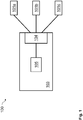
- Fig. 1 shows a schematic diagram of a system 100 for detecting plastics, macro-plastics, micro-plastics and nano-plastics in a maritime, estuary or river environment.
- the system 100 comprises a plurality of detection devices 101a, 101b, 101c for detecting the plastics, the macro-plastics, the micro-plastics and the nano-plastics in the environment, the detection devices 101a, 101b, 101c being configured for detection using different detection wavelengths.
- the system 100 further comprises a data processing device 103, comprising a communication interface 104 and a processor 105.
- the communication interface 104 is configured to receive detection signals from the plurality of detection devices 101a, 101b, 101c.
- the processor 105 is configured to determine locations of the plastics, the macro-plastics, the micro-plastics and the nano-plastics in the environment upon the basis of the received detection signals within a common coordinate system.
- Fig. 2 shows a schematic diagram of a method 200 for operating a system for detecting plastics, macro-plastics, micro-plastics and nano-plastics in a maritime, estuary or river environment.
- the system comprises a plurality of detection devices and a data processing device comprising a communication interface and a processor.
- the detection devices are configured for detection using different detection wavelengths.
- the method 200 comprises detecting 201, by the plurality of detection devices, the plastics, the macro-plastics, the micro-plastics and the nano-plastics in the environment, receiving 203, by the communication interface, detection signals from the plurality of detection devices, and determining 205, by the processor, locations of the plastics, the macro-plastics, the micro-plastics and the nano-plastics in the environment upon the basis of the received detection signals within a common coordinate system.
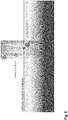
- Fig. 3 shows a schematic diagram of a maritime vessel comprising a system 100 for detecting plastics 301a, macro-plastics 301b, micro-plastics 301c, and nano-plastics 301d in a maritime, estuary or river environment.
- the system 100 is mounted on a mast of the maritime vessel.
- the system 100 may be arranged on a wide variety of platforms, e.g., any martime vessel, submarine, offshore plaftform, pier, aquaculture tank, and the like.
- the system 100 may be mounted on any surface vessel or coastal infrastructure.
- a Ladar may be used as a detection device.
- the in-situ Ladar may measure basic plastic types and quantities.
- the Ladar in-situ observations may be fed into circulation models and may be used to validate satellite observations.
- an enhanced knowledge of the origin of the plastics 301a, the macro-plastics 301b, the micro-plastics 301c, and the nano-plastics 301d may be provided. Furthermore, knowledge of the location and the type of plastic may facilitate cost-efficient clean-up operations in the environment.
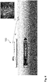
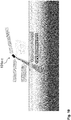
- Fig. 4 shows a schematic diagram of a maritime vessel comprising a system 100 for detecting plastics, macro-plastics, micro-plastics, and nano-plastics in a maritime, estuary or river environment.
- a Ladar may be used as a detection device.
- the laser beam is transmitted towards the water surface at an angle ⁇ i and is refracted into the water at an angle ⁇ w .
- the azimuthal width of the laser beam may e.g. be 3,0°.
- the laser beam comprises a plurality of different wavelength, which may be generated simultaneously or sequentially for detecting the plastics, the macro-plastics, the micro-plastics, and the nano-plastics.
- the laser beam interacts with the plastics, the macro-plastics, the micro-plastics, and the nano-plastics in the water.
- the plurality of different wavelength may be used for detecting the plastics, the macro-plastics, the micro-plastics, and the nano-plastics.
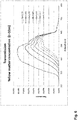
- Fig. 5 shows a schematic diagram illustrating the scattering within water in dependence of wavelength. As can be seen, the scattering decreases with increasing wavelength.
- Fig. 7 shows a schematic diagram of different laser beams having different wavelengths.
- An ultraviolet laser beam may be suitable to detect organic materials; a blue laser beam may be suitable to detect viruses and bacteria; a blue-green laser beam may be suitable to detect micro-plastics; a green laser beam may be suitable to detect macro-plastics; and a red laser beam may be suitable to detect further objects, plastics and other man made material.
- the system may provide a multi-spectral Ladar for the selective detection of the plastics.
- the multi-spectral Ladar may be realized using different single-spectral Ladars as different detection devices. However, the multi-spectral Ladar may also be realized within a single detection device.
- Laser / Light for detection may particularly be suitable since it penetrates water, and reflects from the plastics, the macro-plastics, the micro-plastics, and the nano-plastics.
- the penetration may amout to depths of e.g. 1 to 10 meters.
- the nano-plastics may be formed by very small fibers, the micro-plastics may be formed by small fibers, and the macro-plastics may be formed by larger plastic objects.
- the macro-plastics, the micro-plastics, and the nano-plastics may be dispensed within the water.
- the plastics may refer to larger plastic objects, and may float on the water.
- Fig. 8 shows a schematic diagram of a multi-spectral laser beam.
- the multi-spectral laser beam comprises a plurality of different wavelengths for detecting the macro-plastics, the micro-plastics, and the nano-plastics dispensed within the water.
- the system may be capable of mitigating the effect of particles dispensed in the air.
- the system may perform a selective detection process.
- Fig. 9 shows a schematic diagram of a blue-green laser beam.
- the illumination of the water by the blue-green laser beam may allow for providing a high resolution 3D imaging and/or a high sensitivity 2D imaging for detecting plastics, macro-plastics, micro-plastics and nano-plastics on or below the water surface.
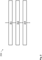
- Fig. 10 shows a schematic diagram of a plurality of detection devices 101a, 101b, 101c.
- the detection devices 101a, 101b, 101c may be arranged within an equipment module.
- the detection devices 101a, 101b, 101c may e.g. be realized as a Ladar, Radar and Imager.
- the plurality of detection devices 101a, 101b, 101c may be equipped with a scanning head, in particular an optical scanning head, for wide swath mapping.
- the plurality of detection devices 101a, 101b, 101c may provide a multi-purpose gated viewing imaging sensor beam.
- Red and ultraviolet laser beams may be used for macro-plastic detection; UV laser beams may be used for nano-plastics and organic substance detection; and blue-green laser beams may be used for detection of micro-plastics.
- the system may be used for a plurality of applications and purposes.
- the system may e.g. be used for facilitating clean-up operations in the environment.
- the system may be used in military applications for detection of submarines / divers / floating mines; in fishery applications for pelagic fish mapping and water turbidity determination; in safety applications for collision avoidance; in security applications for surveillance below and above the water surface; and in charting applications for sea floor mapping / bathymetry.
- the system may be deployed in multi-purpose applications, and may provide a cost-effective solution for detection, classification and mapping within maritime, estuary or river environments.
- the system can provide information on plastics spatial distribution. This may be achieved by spatial mapping through the use scanning and spatial/temporal measurement.
- the system can provide information on plastics hotspots. This may be achieved by accurate local measurements.
- the system can provide quantitative information on plastics. This may be achieved by classification methods.
- the system can be used on a variety of platforms. This may be achieved by a modular and flexible construction, and/or the use of microelectronics, small laser diodes, use of fiberoptics for light piping, and a sensor head separable from the electronics.
- the system can provide precise geolocation of plastics in the ocean. This may be achieved by using GPS, attitude control, and/or laser range finding.
- the system can provide indication of vertical distribution of plastics. This may be achieved by using of wavelengths that penetrate the water column, and/or multiplexed colours, in the range of UV through visible, to infrared.
- the system can provide a classification of plastics types. This may be achieved by using multiplexed colours, in the range of UV through visible, to infrared, by using spectroscopy, and/or using fluorescence.
- the system can identify specific plastics. This may be achieved by deciding on chemical composition and size distribution, and/or by using multiplexed colours, in the range of UV through visible, to infrared, by using spectroscopy, by using fluorescence, by using collimated laser light to 1mrad, and/or by using of high range resolution to 10cm.
- the system can detect and classify nano plastics.
- plastics broken down to particles smaller than 1 micrometre this may be achieved by using light with wavelengths smaller than 1 micrometer, e.g. 300nm, enabling an interaction with extremely small particles through Rayleigh scattering. Also other optical effects such as fluorescence and Raman scattering may be considered.
- the system can detect and classify micro-plastics. To work with plastics with particle sizes micrometer to millimeter, this may be achieved by using micrometer scale light providing detection of plastics by spatial resonance and by semi specular reflection.
- the system can detect and classify macro-plastics. To work with plastics with sizes larger than millimeter to large plastic objects, this may be achieved by detecting objects by specular reflection and by diffuse scattering of light from objects.
- the system can discriminate between plastics and natural phenomena and can operate in natural waters. This may be achieved by using multiplexed colours, in the range of UV through visible, to infrared, by using spectroscopy, by using fluorescence, by using of collimated laser light to 1mrad, and/or by using high range resolution to 10cm.
- the system can operate irrespective of fog, rain and sunshine. This may be achieved by using high performance coding of the laser waveform with large entropy, e.g. using Golay codes.
- the system can operate in different sea states and/or can isolate reflection from the sea surface. This may be achieved by using high performance codes which also have low sidelobes, and/or high spatial precision, e.g. to 10cm.
- the system can use additional data from camera sensors and/or use signal processing and/or object detection from optical sensors, in conjunction with data fusion with data from a LADAR.
- the system can use additional data from radar sensors and/or use signal processing and/or object detection from radar sensors, in conjunction with data fusion with data from a LADAR.
- the system can use additional data from acoustical sensors and/or use signal processing and/or object detection from acoustical sensors or sonars, in conjunction with data fusion with data from a LADAR.
- the system can use additional data from chemical sensors, e.g. in-situ.
- a geolocation based processing may be used.
- the system can work with ocean current models. This may be achieved by fusing LADAR data measurements at several locations and several time locations with historic/NOWcast/FORECAST ocean and current models.
- the system is self-learning.
- the system may learn by automatic and/or manual feedback to provide accurate information.
- the system may use Al (Artificial Intelligence) methods for self-learning and/or self-optimisation.
- the system can be installed on a maritime vessel, e.g. a ship.
- the system can be installed on a submerged vessel. This may be achieved because electronics may have small size, low power consumption, and/or light being fed by flexible fiber optics to apertures in fuselage.
- the system can be used on an aircraft. This may be achieved because electronics may have small size, low power consumption, and/or light being fed by flexible fiber optics to apertures in fuselage.
- the system can be used on an autonomous vessels/aircraft.
- the system may have included a GPS (surface, aircraft) and an INS (Inertial Navigation System), and/or may use a precise laser beam at 1 milliradian.
- GPS surface, aircraft
- INS Inertial Navigation System
- the system can sample large expanses of sea.
- the system can operate on fast ship or aircraft, may provide instantaneous measurements, can sample in trajectories, can have side-scanning to generate data over wide swaths, and/or can operate from large altitudes to cover large areas.
- the system can investigate specific areas to give detailed data.
- the system can operate from stationary/hovering platforms, can increase resolution and sensitivity by use of adaptive processing, and/or can be supported by precise navigation tools.
- the system is modular and configurable to adapt to user needs. This may be achieved by using installations where electronics and sensor heads are at different locations, separated by fiber e.g. by up to 500m, suitable mechanical implementation, usage of microelectronics, fiber optics, low cost components, software based design, remote software control, and/or open interfaces.
- the system is small and compact. This may allow the system to be used on even very small platforms, down to small UAVs and drones. This may be achieved by suitable mechanical implementation, usage of microelectronics, fiber optics, low cost components, software based design, remote software control, and/or open interfaces.
- the system is inexpensive to facilitate large scale deployment. This may be achieved by suitable mechanical implementation, usage of microelectronics, fiber optics, low cost components, software based design, remote software control, and/or open interfaces.
- the system is eye safe to facilitate use in specific platforms. This may be achieved using a programmable laser power, a controlled laser beam divergence, day and night operating modes, and/or selectable wavelengths including eye safe wavelengths.
Landscapes
- Engineering & Computer Science (AREA)
- Radar, Positioning & Navigation (AREA)
- Remote Sensing (AREA)
- Physics & Mathematics (AREA)
- Computer Networks & Wireless Communication (AREA)
- General Physics & Mathematics (AREA)
- Electromagnetism (AREA)
- Investigating Or Analysing Materials By Optical Means (AREA)
- Optical Radar Systems And Details Thereof (AREA)
Description
- The present invention relates to the field of detection and classification of floating plastics, macro-plastics, micro-plastics and nano-plastics in water.
- Increasing quantities of plastics, macro-plastics, micro-plastics and nano-plastics floating or dispensed within water, such as in maritime, estuary or river environments pose an increasing challenge for the environment.
- The detection and classification of these different plastics is of particular relevance for facilitating clean-up operations in the environment. However, common techniques allow only for a coarse detection and classifications of these different plastics.
- Document
US 2005/007448 A1 relates to a remote 3-D imaging system which uses an illumination source to establish the relationship of the image features to the system, which is displayed by virtue of calculations. - Document
EP 2 866 052 A1 relates to a system for monitoring a maritime environment. The system includes a plurality of detection devices for detecting objects in the maritime environment according to different object detection schemes. A processor determines locations of the objects upon the basis of received detection signals. - Document
US 2013/070556 A1 relates to an aircraft location system for locating aircraft in water environments. The system comprises an aircraft structure and a number of acoustic reflectors associated with the aircraft structure. The number of acoustic reflectors generate first sound signals in response to receiving second sound signals. - It is an object of the present invention to provide a concept for detecting plastics, macro-plastics, micro-plastics and nano-plastics in a maritime, estuary or river environment.
- This object is achieved by the features of the independent claims. Further implementation forms are apparent from the dependent claims, the description and the figures.
- The invention is based on the finding that different detection wavelengths may be used for detecting the plastics, the macro-plastics, the micro-plastics and the nano-plastics in the maritime, estuary or river environment. Due to different characteristics of plastics, macro-plastics, micro-plastics and nano-plastics at different detection wavelengths, a detection and/or classification of the different plastics may be achieved with increased accuracy.
- The nano-plastics may be formed by very small fibers, the micro-plastics may be formed by small fibers, and the macro-plastics may be formed by larger plastic objects. The macro-plastics, the micro-plastics, and the nano-plastics may be dispensed within the water. The plastics may refer to larger plastic objects, and may float on the water.
- According to a first aspect, the invention relates to a system for detecting plastics, macro-plastics, micro-plastics and nano-plastics in a maritime, estuary or river environment. The system comprises a plurality of detection devices for detecting the plastics, the macro-plastics, the micro-plastics and the nano-plastics in the environment, the detection devices being configured for detection using different detection wavelengths. The system further comprises a data processing device, comprising a communication interface and a processor. The communication interface is configured to receive detection signals from the plurality of detection devices. The processor is configured to determine locations of the plastics, the macro-plastics, the micro-plastics and the nano-plastics in the environment upon the basis of the received detection signals within a common coordinate system.
- In an embodiment of the system, the different detection wavelengths are used for evaluating elastic and/or non-elastic scattering of visible and/or invisible light, wherein the processor is configured to perform at least one data processing method, in particular a real time processing method and/or an artificial intelligence processing method, and wherein the plurality of detection devices comprise micro-integrated electronics, laser diodes, fiber-optics for light piping and/or a distributed components layout.
- In an embodiment of the system, the system is configured to provide information on plastics, macro-plastics, micro-plastics and nano-plastics spatial distribution within the environment using spatial mapping through the use of scanning and/or spatial measurements and/or temporal measurements with in-situ observation feeds into circulation models, and wherein the processor is configured to validate satellite observations.
- In an embodiment of the system, the system is configured to use as one of the plurality of detection devices, a multispectral laser/light detection and ranging device (Ladar or Lidar) for selective plastic detection and plastic type classification.
- In an embodiment of the system, the system is configured to use multiple simultaneous and/or sequential wavelengths for optimum detection and classification, in particular a blue-green laser beam for micro-plastics detection, a green laser beam for macro-plastics detection and/or a red laser beam for the detection of plastics or objects.
- In an embodiment of the system, the system is configured to use a UV beam for nano-plastic and/or organic substance detection, wherein the system is configured to evaluate elastic scattering to provide specific signatures of substances, in particular evaluating fluorescence to detect and discriminate against organic material.
- In an embodiment of the system, at least one of the plurality of detection devices is configured to generate a multispectral Laser/Light beam to penetrate a water surface within the environment and to obtain a high sensitivity 2D image and/or a high-
resolution 3D image. - In an embodiment of the system, the processor is configured to provide information on plastics, macro-plastics, micro-plastics and nano-plastics spatial hotspots using the detections signals from the plurality of detection devices to provide accurate local measurements.
- In an embodiment of the system, the processor is configured to provide quantitative information, in particular mass per volume and/or plastics size distribution information, on the plastics, the macro-plastics, the micro-plastics and the nano-plastics on the basis of the received detection signals.
- In an embodiment of the system, the processor is configured to use a classification method implemented to provide classification of plastics, macro-plastics, micro-plastics and nano-plastics types using multiplexed colours, in particular in the range of UV through visible, to infrared, the use of spectroscopy and/or the use of fluorescence for detection and classification within the environment.
- In an embodiment of the system, the processor is configured to use the received detection signals in conjunction with an integrated GPS position signal, an attitude control signal, and/or a laser range finding signal, to provide geo-location information of the plastics, the macro-plastics, the micro-plastics and the nano-plastics in the environment.
- In an embodiment of the system, the processor is configured to provide an indication of a vertical distribution of the plastics, the macro-plastics, the micro-plastics and the nano-plastics in the environment, wherein at least one of the plurality of detection devices is configured to use wavelengths that penetrate a water column by using multiplexed colours, in particular in the range of UV through visible, to infrared.
- In an embodiment of the system, the processor is configured to identify specific plastics, macro-plastics, micro-plastics and nano-plastics chemical composition and/or size distribution using multiplexed colours, in particular in the range of UV through visible, to infrared, the use of spectroscopy, the use of fluorescence, the use of collimated laser light to 1mrad and/or the use of high range resolution to millimetre and centimetre scale.
- In an embodiment of the system, the processor is configured to detect and classify nano-plastics, including plastics broken down to particles smaller than 1 micrometre, wherein at least one of the plurality of detection devices is configured to use a light with wavelengths smaller than 1 micrometre, in particular 300nm, which enables interaction with extremely small particles through Rayleigh scattering and/or other optical effects such as fluorescence and Raman scattering.
- In an embodiment of the system, the processor is configured to detect and classify micro-plastics and to work with plastics with particle sizes in the micrometre to millimetre range, wherein at least one of the plurality of detection devices is configured to use a micrometre scale light that provides detection of plastics by spatial resonance and/or by semi-specular reflection.
- In an embodiment of the system, the processor is configured to detect and classify macro-plastics and work with plastics with sizes larger than millimetre to large plastic objects, wherein at least one of the plurality of detection devices is configured to use specular reflection and diffusing of the scattering of light from the identified macro-plastics.
- In an embodiment of the system, the processor is configured to discriminate between plastics and natural phenomena, in particular waves, natural algae, fish and organisms, natural occurring hydrocarbons and oil, and/or air bubbles, wherein the system is operable in different sea states and natural waters, wherein the processor is configured to isolate reflections from a water surface using high performance codes having low sidelobes and/or a high spatial precision, in particular to 10cm, allowing operation of the system.
- In an embodiment of the system, the processor is configured to use additional data from camera sensors, radars or high resolution radars, acoustical sensors or sonars, other data provided by signal processing and object detection from optical sensors, along with data fusion with data from a laser/light detection and ranging (Ladar or Lidar) device.
- In an embodiment of the system, the communication interface is configured to receive data insitu from chemical sensors, wherein the processor is configured to use geolocation-based processing.
- In an embodiment of the system, the processor is configured to operate with and receive input from ocean current models, waves models and/or wind models, in particular Meta-Ocean Models, by fusing laser/light detection and ranging (Ladar or Lidar) device data measurement at several locations and several time locations with historic/NOWcast/FORECAST models, for allowing plastic's precise location detection after a period of time.
- In an embodiment of the system, the system is operable in a configuration that can be used, mounted and/or located on variety of platforms, vessels, sub-merged vessels, aircrafts, drones, and autonomous vessels/aircrafts, amongst others, using its modular and flexible construction, by being small and compact in size, with its electronics being of small size, low power consumption, light is fed by flexible fibre optics to apertures in fuselage and the configurations to use its included GPS (surface, aircraft) and Inertial Navigation System (INS) and a laser beam at 1 miliradian or more according to a user's configurations.
- In an embodiment of the system, the system is operable in a configuration that can investigate specific areas in the environment to provide detailed data and can be located on stationary/hovering platforms which can increase resolution and sensitivity by use of adaptive processing and supported by precise navigation tools, in particular GPS when a Ladar is above water, or another precise navigation system when a Ladar is under water.
- In an embodiment of the system, the system is operable in a configuration that allows a large scale of deployment to cover great lengths of area for detecting the plastics, the macro-plastics, the micro-plastics and the nano-plastics in the environment, in particular due to its inexpensive components and production methods, software based design, remote software control and/or open interfaces.
- In an embodiment of the system, the system is operable in a configuration that is configured to sample large expanses of sea as it can operate from large altitudes to cover large areas and can also be mounted on fast vessels or aircrafts with instantaneous measurements and sample in trajectories and can have side-scanning to generate data over a wide swath.
- In an embodiment of the system, the system is operable in a configuration wherein a Ladar/Lidar sensor is supplemented with other sensors, and wherein the sensors form one kit/black box that is able to monitor a footprint of a certain geographical area, and wherein the footprint can be expanded by scanning around the sensors for 360 degrees, and the footprint may sweep around in a circle and scan that specific geographical area.
- In an embodiment of the system, the system is operable in a configuration wherein there are more kits/black boxes that have a similar footprint, such that a plurality of scanning units can be aligned in a line or a grid, connected with fiber optics to a communication network, and each of the units is configured either to scan in a dedicated footprint or each of the units is configured to scan in circles around the respective sensor, for covering a greater area of scanning when more scanning units are used.
- In an embodiment of the system, the system is operable in a configuration wherein a black box/kit with a sensor, either on a fixed point, in particular a buoy or a platform, or on a vehicle that is on the move, in particular a vessel, is linked with a drift model, so as to determine the trajectories of the plastic over the course of days, weeks and/or months, while taking into account factors of wind fetch, wave interaction and/or ocean currents, and to determine where the plastic's final geographical location will be over the period of time.
- In an embodiment of the system, the system is configured to operate irresectable of atmospheric and/or sea-state conditions, in particular fog, rain, ice, snow, sun glitters, and/or sunshine, by using high performance coding of a laser waveform with large entropy, in particular Golay codes.
- In an embodiment of the system, the system is configured to be self-learning by automatic and manual feedback to provide accurate information and can include Artificial Intelligence (Al) methods for self-learning and self-optimisation such as when an object is identified and verified using correlation techniques to patterns, geo-structural information, chemical information amongst others, wherein this information can be integrated in the self-learning algorithm and used with the return signals for plastic detection and identification.
- In an embodiment of the system, the system is modular and configurable to adapt to user needs, in particular having installations where electronics and sensors are arranged at different locations, separated by fibre up to 500m for short distances and up to several kilometres for long distances, mechanical implementation, micro-electronics, fibre optics, cost related to the system, software based design, remote software control, and/or open interfaces.
- In an embodiment of the system, the system is safe for the eyes of the user and the people in its proximity and provides safety from high illuminative optical power, making it safe to use in different conditions with programmable laser power, controlled laser beam divergence, day and night operating modes, and/or a selectable wavelength which includes an eye safety wavelength.
- According to a second aspect, the invention relates to a method for operating a system for detecting plastics, macro-plastics, micro-plastics and nano-plastics in a maritime, estuary or river environment. The system comprises a plurality of detection devices and a data processing device comprising a communication interface and a processor. The detection devices are configured for detection using different detection wavelengths. The method comprises detecting, by the plurality of detection devices, the plastics, the macro-plastics, the micro-plastics and the nano-plastics in the environment, receiving, by the communication interface, detection signals from the plurality of detection devices, and determining, by the processor, locations of the plastics, the macro-plastics, the micro-plastics and the nano-plastics in the environment upon the basis of the received detection signals within a common coordinate system.
- The method can be performed by the system. Further features of the method directly result from the features and/or the functionality of the system.
- According to a third aspect, the invention relates to a computer program for performing the method when executed by a system, in particular to provide relevant information, including location, characterisation and identification of the plastics detected.
- Further embodiments of the invention will be described with respect to the following figures, in which:
-
Fig. 1 shows a schematic diagram of a system for detecting plastics, macro-plastics, micro-plastics and nano-plastics in a maritime, estuary or river environment; -
Fig. 2 shows a schematic diagram of a method for operating a system for detecting plastics, macro-plastics, micro-plastics and nano-plastics in a maritime, estuary or river environment; -
Fig. 3 shows a schematic diagram of a maritime vessel comprising a system for detecting plastics, macro-plastics, micro-plastics, and nano-plastics in a maritime, estuary or river environment; -
Fig. 4 shows a schematic diagram of a maritime vessel comprising a system for detecting plastics, macro-plastics, micro-plastics, and nano-plastics in a maritime, estuary or river environment; -
Fig. 5 shows a schematic diagram illustrating the scattering within water in dependence of wavelength; -
Fig. 6 shows a schematic diagram illustrating the transmission within water in dependence of wavelength; -
Fig. 7 shows a schematic diagram of different laser beams having different wavelengths; -
Fig. 8 shows a schematic diagram of a multi-spectral laser beam; -
Fig. 9 shows a schematic diagram of a blue-green laser beam; and -
Fig. 10 shows a schematic diagram of a plurality of detection devices. - In the following description, reference is made to the accompanying figures, which form part of the disclosure, and which show, by way of illustration, specific aspects of embodiments of the invention or specific aspects in which embodiments of the invention may be used. It is understood that embodiments of the invention may be used in other aspects and comprise structural or logical changes not depicted in the figures. The following detailed description, therefore, is not to be taken in a limiting sense, and the scope of the invention is defined by the appended claims.
- For instance, it is to be understood that a disclosure in connection with a described method may also hold true for a corresponding system configured to perform the method and vice versa. For example, if one or a plurality of specific method steps are described, a corresponding system may include one or a plurality of units, e.g. functional units, to perform the described one or plurality of method steps (e.g. one unit performing the one or plurality of steps, or a plurality of units each performing one or more of the plurality of steps), even if such one or more units are not explicitly described or illustrated in the figures. On the other hand, for example, if a specific system is described based on one or a plurality of units, e.g. functional units, a corresponding method may include one step to perform the functionality of the one or plurality of units (e.g. one step performing the functionality of the one or plurality of units, or a plurality of steps each performing the functionality of one or more of the plurality of units), even if such one or plurality of steps are not explicitly described or illustrated in the figures. Further, it is understood that the features of the various exemplary embodiments and/or aspects described herein may be combined with each other, unless specifically noted otherwise.
-
Fig. 1 shows a schematic diagram of asystem 100 for detecting plastics, macro-plastics, micro-plastics and nano-plastics in a maritime, estuary or river environment. - The
system 100 comprises a plurality ofdetection devices detection devices system 100 further comprises adata processing device 103, comprising acommunication interface 104 and aprocessor 105. Thecommunication interface 104 is configured to receive detection signals from the plurality ofdetection devices processor 105 is configured to determine locations of the plastics, the macro-plastics, the micro-plastics and the nano-plastics in the environment upon the basis of the received detection signals within a common coordinate system. -
Fig. 2 shows a schematic diagram of amethod 200 for operating a system for detecting plastics, macro-plastics, micro-plastics and nano-plastics in a maritime, estuary or river environment. The system comprises a plurality of detection devices and a data processing device comprising a communication interface and a processor. The detection devices are configured for detection using different detection wavelengths. - The
method 200 comprises detecting 201, by the plurality of detection devices, the plastics, the macro-plastics, the micro-plastics and the nano-plastics in the environment, receiving 203, by the communication interface, detection signals from the plurality of detection devices, and determining 205, by the processor, locations of the plastics, the macro-plastics, the micro-plastics and the nano-plastics in the environment upon the basis of the received detection signals within a common coordinate system. -
Fig. 3 shows a schematic diagram of a maritime vessel comprising asystem 100 for detectingplastics 301a, macro-plastics 301b, micro-plastics 301c, and nano-plastics 301d in a maritime, estuary or river environment. - Exemplarily, the
system 100 is mounted on a mast of the maritime vessel. In general, however, thesystem 100 may be arranged on a wide variety of platforms, e.g., any martime vessel, submarine, offshore plaftform, pier, aquaculture tank, and the like. In other words, thesystem 100 may be mounted on any surface vessel or coastal infrastructure. - In this example, a Ladar may be used as a detection device. The in-situ Ladar may measure basic plastic types and quantities. The Ladar in-situ observations may be fed into circulation models and may be used to validate satellite observations.
- As a result, an enhanced knowledge of the origin of the
plastics 301a, the macro-plastics 301b, the micro-plastics 301c, and the nano-plastics 301d may be provided. Furthermore, knowledge of the location and the type of plastic may facilitate cost-efficient clean-up operations in the environment. -
Fig. 4 shows a schematic diagram of a maritime vessel comprising asystem 100 for detecting plastics, macro-plastics, micro-plastics, and nano-plastics in a maritime, estuary or river environment. - In this example, a Ladar may be used as a detection device. The laser beam is transmitted towards the water surface at an angle θi and is refracted into the water at an angle θw. The azimuthal width of the laser beam may e.g. be 3,0°.
- The laser beam comprises a plurality of different wavelength, which may be generated simultaneously or sequentially for detecting the plastics, the macro-plastics, the micro-plastics, and the nano-plastics. The laser beam interacts with the plastics, the macro-plastics, the micro-plastics, and the nano-plastics in the water.
- The plurality of different wavelength may be used for detecting the plastics, the macro-plastics, the micro-plastics, and the nano-plastics.
-
Fig. 5 shows a schematic diagram illustrating the scattering within water in dependence of wavelength. As can be seen, the scattering decreases with increasing wavelength. -
Fig. 6 shows a schematic diagram illustrating the transmission within water in dependence of wavelength. As can be seen, the transmission varies with wavelength. Exemplary coefficients are given as follows: GS=0 for clean sea water, GS=0.07 for north sea water, and GS=0.24 for Baltic sea water. -
Fig. 7 shows a schematic diagram of different laser beams having different wavelengths. An ultraviolet laser beam may be suitable to detect organic materials; a blue laser beam may be suitable to detect viruses and bacteria; a blue-green laser beam may be suitable to detect micro-plastics; a green laser beam may be suitable to detect macro-plastics; and a red laser beam may be suitable to detect further objects, plastics and other man made material. - The system may provide a multi-spectral Ladar for the selective detection of the plastics. The multi-spectral Ladar may be realized using different single-spectral Ladars as different detection devices. However, the multi-spectral Ladar may also be realized within a single detection device.
- Laser / Light for detection may particularly be suitable since it penetrates water, and reflects from the plastics, the macro-plastics, the micro-plastics, and the nano-plastics. The penetration may amout to depths of e.g. 1 to 10 meters.
- The nano-plastics may be formed by very small fibers, the micro-plastics may be formed by small fibers, and the macro-plastics may be formed by larger plastic objects. The macro-plastics, the micro-plastics, and the nano-plastics may be dispensed within the water. The plastics may refer to larger plastic objects, and may float on the water.
-
Fig. 8 shows a schematic diagram of a multi-spectral laser beam. The multi-spectral laser beam comprises a plurality of different wavelengths for detecting the macro-plastics, the micro-plastics, and the nano-plastics dispensed within the water. The system may be capable of mitigating the effect of particles dispensed in the air. The system may perform a selective detection process. -
Fig. 9 shows a schematic diagram of a blue-green laser beam. The illumination of the water by the blue-green laser beam may allow for providing ahigh resolution 3D imaging and/or a high sensitivity 2D imaging for detecting plastics, macro-plastics, micro-plastics and nano-plastics on or below the water surface. -
Fig. 10 shows a schematic diagram of a plurality ofdetection devices detection devices detection devices - The plurality of
detection devices detection devices - Red and ultraviolet laser beams may be used for macro-plastic detection; UV laser beams may be used for nano-plastics and organic substance detection; and blue-green laser beams may be used for detection of micro-plastics.
- The system may be used for a plurality of applications and purposes. The system may e.g. be used for facilitating clean-up operations in the environment. Furthermore, the system may be used in military applications for detection of submarines / divers / floating mines; in fishery applications for pelagic fish mapping and water turbidity determination; in safety applications for collision avoidance; in security applications for surveillance below and above the water surface; and in charting applications for sea floor mapping / bathymetry. The system may be deployed in multi-purpose applications, and may provide a cost-effective solution for detection, classification and mapping within maritime, estuary or river environments.
- Further embodiments of the system are defined as follows:
In an embodiment, the system can provide information on plastics spatial distribution. This may be achieved by spatial mapping through the use scanning and spatial/temporal measurement. - In an embodiment, the system can provide information on plastics hotspots. This may be achieved by accurate local measurements.
- In an embodiment, the system can provide quantitative information on plastics. This may be achieved by classification methods.
- In an embodiment, the system can be used on a variety of platforms. This may be achieved by a modular and flexible construction, and/or the use of microelectronics, small laser diodes, use of fiberoptics for light piping, and a sensor head separable from the electronics.
- In an embodiment, the system can provide precise geolocation of plastics in the ocean. This may be achieved by using GPS, attitude control, and/or laser range finding.
- In an embodiment, the system can provide indication of vertical distribution of plastics. This may be achieved by using of wavelengths that penetrate the water column, and/or multiplexed colours, in the range of UV through visible, to infrared.
- In an embodiment, the system can provide a classification of plastics types. This may be achieved by using multiplexed colours, in the range of UV through visible, to infrared, by using spectroscopy, and/or using fluorescence.
- In an embodiment, the system can identify specific plastics. This may be achieved by deciding on chemical composition and size distribution, and/or by using multiplexed colours, in the range of UV through visible, to infrared, by using spectroscopy, by using fluorescence, by using collimated laser light to 1mrad, and/or by using of high range resolution to 10cm.
- In an embodiment, the system can detect and classify nano plastics. To work with plastics broken down to particles smaller than 1 micrometre, this may be achieved by using light with wavelengths smaller than 1 micrometer, e.g. 300nm, enabling an interaction with extremely small particles through Rayleigh scattering. Also other optical effects such as fluorescence and Raman scattering may be considered.
- In an embodiment, the system can detect and classify micro-plastics. To work with plastics with particle sizes micrometer to millimeter, this may be achieved by using micrometer scale light providing detection of plastics by spatial resonance and by semi specular reflection.
- In an embodiment, the system can detect and classify macro-plastics. To work with plastics with sizes larger than millimeter to large plastic objects, this may be achieved by detecting objects by specular reflection and by diffuse scattering of light from objects.
- In an embodiment, the system can discriminate between plastics and natural phenomena and can operate in natural waters. This may be achieved by using multiplexed colours, in the range of UV through visible, to infrared, by using spectroscopy, by using fluorescence, by using of collimated laser light to 1mrad, and/or by using high range resolution to 10cm.
- In an embodiment, the system can operate irrespective of fog, rain and sunshine. This may be achieved by using high performance coding of the laser waveform with large entropy, e.g. using Golay codes.
- In an embodiment, the system can operate in different sea states and/or can isolate reflection from the sea surface. This may be achieved by using high performance codes which also have low sidelobes, and/or high spatial precision, e.g. to 10cm.
- In an embodiment, the system can use additional data from camera sensors and/or use signal processing and/or object detection from optical sensors, in conjunction with data fusion with data from a LADAR.
- In an embodiment, the system can use additional data from radar sensors and/or use signal processing and/or object detection from radar sensors, in conjunction with data fusion with data from a LADAR.
- In an embodiment, the system can use additional data from acoustical sensors and/or use signal processing and/or object detection from acoustical sensors or sonars, in conjunction with data fusion with data from a LADAR.
- In an embodiment, the system can use additional data from chemical sensors, e.g. in-situ. A geolocation based processing may be used.
- In an embodiment, the system can work with ocean current models. This may be achieved by fusing LADAR data measurements at several locations and several time locations with historic/NOWcast/FORECAST ocean and current models.
- In an embodiment, the system is self-learning. The system may learn by automatic and/or manual feedback to provide accurate information. The system may use Al (Artificial Intelligence) methods for self-learning and/or self-optimisation.
- In an embodiment, the system can be installed on a maritime vessel, e.g. a ship.
- In an embodiment, the system can be installed on a submerged vessel. This may be achieved because electronics may have small size, low power consumption, and/or light being fed by flexible fiber optics to apertures in fuselage.
- In an embodiment, the system can be used on an aircraft. This may be achieved because electronics may have small size, low power consumption, and/or light being fed by flexible fiber optics to apertures in fuselage.
- In an embodiment, the system can be used on an autonomous vessels/aircraft. The system may have included a GPS (surface, aircraft) and an INS (Inertial Navigation System), and/or may use a precise laser beam at 1 milliradian.
- In an embodiment, the system can sample large expanses of sea. The system can operate on fast ship or aircraft, may provide instantaneous measurements, can sample in trajectories, can have side-scanning to generate data over wide swaths, and/or can operate from large altitudes to cover large areas.
- In an embodiment, the system can investigate specific areas to give detailed data. The system can operate from stationary/hovering platforms, can increase resolution and sensitivity by use of adaptive processing, and/or can be supported by precise navigation tools.
- In an embodiment, the system is modular and configurable to adapt to user needs. This may be achieved by using installations where electronics and sensor heads are at different locations, separated by fiber e.g. by up to 500m, suitable mechanical implementation, usage of microelectronics, fiber optics, low cost components, software based design, remote software control, and/or open interfaces.
- In an embodiment, the system is small and compact. This may allow the system to be used on even very small platforms, down to small UAVs and drones. This may be achieved by suitable mechanical implementation, usage of microelectronics, fiber optics, low cost components, software based design, remote software control, and/or open interfaces.
- In an embodiment, the system is inexpensive to facilitate large scale deployment. This may be achieved by suitable mechanical implementation, usage of microelectronics, fiber optics, low cost components, software based design, remote software control, and/or open interfaces.
- In an embodiment, the system is eye safe to facilitate use in specific platforms. This may be achieved using a programmable laser power, a controlled laser beam divergence, day and night operating modes, and/or selectable wavelengths including eye safe wavelengths.
-
- 100
- System
- 101a
- Detection device
- 101b
- Detection device
- 101c
- Detection device
- 103
- Data processing device
- 104
- Communication interface
- 105
- Processor
- 200
- Method
- 201
- Detecting
- 203
- Receiving
- 205
- Determining
- 301a
- Plastics
- 301b
- Macro-plastics
- 301c
- Micro-plastics
- 301d
- Nano-plastics
Claims (30)
- A system (100) for detecting plastics (301a) in a maritime, estuary or river environment, characterized in that the system is further used for detecting macro-plastics (301b), micro-plastics (301c) and nano-plastics (301d) and that the system (100) comprises:a plurality of detection devices (101a, 101b, 101c) for detecting the plastics (301a), the macro-plastics (301b), the micro-plastics (301c) and the nano-plastics (301d) in the environment, the detection devices (101a, 101b, 101c) being configured for detection using different detection wavelengths; anda data processing device (103), comprising a communication interface (104) and a processor (105), wherein the communication interface (104) is configured to receive detection signals from the plurality of detection devices (101a, 101b, 101c), and wherein the processor (105) is configured to determine locations of the plastics (301a), the macro-plastics (301b), the micro-plastics (301c) and the nano-plastics (301d) in the environment upon the basis of the received detection signals within a common coordinate system.
- The system (100) of claim 1, wherein the different detection wavelengths are used for evaluating elastic and/or non-elastic scattering of visible and/or invisible light, wherein the processor (105) is configured to perform at least one data processing method, in particular a real time processing method and/or an artificial intelligence processing method, and wherein the plurality of detection devices (101a, 101b, 101c) comprise micro-integrated electronics, laser diodes, fiber-optics for light piping and/or a distributed components layout.
- The system (100) of any of the preceding claims, wherein the system (100) is configured to provide information on plastics, macro-plastics, micro-plastics and nano-plastics spatial distribution within the environment using spatial mapping through the use of scanning and/or spatial measurements and/or temporal measurements with in-situ observation feeds into circulation models, and wherein the processor (105) is configured to validate satellite observations.
- The system (100) of any of the preceding claims, wherein the system (100) is configured to use as one of the plurality of detection devices, a multispectral laser/light detection and ranging device for selective plastic detection and plastic type classification.
- The system (100) of any of the preceding claims, wherein the system (100) is configured to use multiple simultaneous and/or sequential wavelengths for optimum detection and classification, in particular a blue-green laser beam for micro-plastics detection, a green laser beam for macro-plastics detection and/or a red laser beam for the detection of plastics or objects.
- The system (100) of any of the preceding claims, wherein the system (100) is configured to use a UV beam for nano-plastic and/or organic substance detection, wherein the system (100) is configured to evaluate elastic scattering to provide specific signatures of substances, in particular evaluating fluorescence to detect and discriminate against organic material.
- The system (100) of any of the preceding claims, wherein at least one of the plurality of detection devices (101a, 101b, 101c) is configured to generate a multispectral Laser/Light beam to penetrate a water surface within the environment and to obtain a high sensitivity 2D image and/or a high-resolution 3D image.
- The system (100) of any of the preceding claims, wherein the processor (105) is configured to provide information on plastics, macro-plastics, micro-plastics and nano-plastics spatial hotspots using the detections signals from the plurality of detection devices (101a, 101b, 101c) to provide accurate local measurements.
- The system (100) of any of the preceding claims, wherein the processor (105) is configured to provide quantitative information, in particular mass per volume and/or plastics size distribution information, on the plastics (301a), the macro-plastics (301b), the micro-plastics (301c) and the nano-plastics (301d) on the basis of the received detection signals.
- The system (100) of any of the preceding claims, wherein the processor (105) is configured to use a classification method implemented to provide classification of plastics, macro-plastics, micro-plastics and nano-plastics types using multiplexed colours, in particular in the range of UV through visible, to infrared, the use of spectroscopy and/or the use of fluorescence for detection and classification within the environment.
- The system (100) of any of the preceding claims, wherein the processor (105) is configured to use the received detection signals in conjunction with an integrated GPS position signal, an attitude control signal, and/or a laser range finding signal, to provide geo-location information of the plastics (301a), the macro-plastics (301b), the micro-plastics (301c) and the nano-plastics (301d) in the environment.
- The system (100) of any of the preceding claims, wherein the processor (105) is configured to provide an indication of a vertical distribution of the plastics (301a), the macro-plastics (301b), the micro-plastics (301c) and the nano-plastics (301d) in the environment, wherein at least one of the plurality of detection devices (101a, 101b, 101c) is configured to use wavelengths that penetrate a water column by using multiplexed colours, in particular in the range of UV through visible, to infrared.
- The system (100) of any of the preceding claims, wherein the processor (105) is configured to identify specific plastics, macro-plastics, micro-plastics and nano-plastics chemical composition and/or size distribution using multiplexed colours, in particular in the range of UV through visible, to infrared, the use of spectroscopy, the use of fluorescence, the use of collimated laser light to 1mrad and/or the use of high range resolution to millimetre and centimetre scale.
- The system (100) of any of the preceding claims, wherein the processor (105) is configured to detect and classify nano-plastics (301d), including plastics broken down to particles smaller than 1 micrometre, wherein at least one of the plurality of detection devices (101a, 101b, 101c) is configured to use a light with wavelengths smaller than 1 micrometre, in particular 300nm, which enables interaction with extremely small particles through Rayleigh scattering and/or other optical effects such as fluorescence and Raman scattering.
- The system (100) of any of the preceding claims, wherein the processor (105) is configured to detect and classify micro-plastics (301c) and to work with plastics with particle sizes in the micrometre to millimetre range, wherein at least one of the plurality of detection devices (101a, 101b, 101c) is configured to use a micrometre scale light that provides detection of plastics by spatial resonance and/or by semi-specular reflection.
- The system (100) of any of the preceding claims, wherein the processor (105) is configured to detect and classify macro-plastics (301b) and work with plastics with sizes larger than millimetre to large plastic objects, wherein at least one of the plurality of detection devices (101a, 101b, 101c) is configured to use specular reflection and diffusing of the scattering of light from the identified macro-plastics (301b).
- The system (100) of any of the preceding claims, wherein the processor (105) is configured to discriminate between plastics and natural phenomena, in particular waves, natural algae, fish and organisms, natural occurring hydrocarbons and oil, and/or air bubbles, wherein the system (100) is operable in different sea states and natural waters, wherein the processor (105) is configured to isolate reflections from a water surface using high performance codes having low sidelobes and/or a high spatial precision, in particular to 10cm, allowing operation of the system (100).
- The system (100) of any of the preceding claims, wherein the processor (105) is configured to use additional data from camera sensors, radars or high resolution radars, acoustical sensors or sonars, other data provided by signal processing and object detection from optical sensors, along with data fusion with data from a laser/light detection and ranging device.
- The system (100) of any of the preceding claims, wherein the communication interface (104) is configured to receive data insitu from chemical sensors, wherein the processor (105) is configured to use geolocation-based processing.
- The system (100) of any of the preceding claims, wherein the processor (105) is configured to operate with and receive input from ocean current models, waves models and/or wind models, in particular Meta-Ocean Models, by fusing laser/light detection and ranging device data measurement at several locations and several time locations with historic/NOWcast/FORECAST models, for allowing plastic's precise location detection after a period of time.
- The system (100) of any of the preceding claims, wherein the system (100) is operable in a configuration that can be used, mounted and/or located on variety of platforms, vessels, sub-merged vessels, aircrafts, drones, and autonomous vessels/aircrafts, amongst others, using its modular and flexible construction, by being small and compact in size, with its electronics being of small size, low power consumption, light is fed by flexible fibre optics to apertures in fuselage and the configurations to use its included GPS and Inertial Navigation System (INS) and a laser beam at 1 miliradian or more according to a user's configurations.
- The system (100) of any of the preceding claims, wherein the system (100) is operable in a configuration that can investigate specific areas in the environment to provide detailed data and can be located on stationary/hovering platforms which can increase resolution and sensitivity by use of adaptive processing and supported by precise navigation tools, in particular GPS when a Ladar is above water, or another precise navigation system when a Ladar is under water.
- The system (100) of any of the preceding claims, wherein the system (100) is operable in a configuration wherein a Ladar/Lidar sensor is supplemented with other sensors, and wherein the sensors form one kit/black box that is able to monitor a footprint of a certain geographical area, and wherein the footprint can be expanded by scanning around the sensors for 360 degrees, and the footprint may sweep around in a circle and scan that specific geographical area.
- The system (100) of any of the preceding claims, wherein the system (100) is operable in a configuration wherein there are more kits/black boxes that have a similar footprint, such that a plurality of scanning units can be aligned in a line or a grid, connected with fiber optics to a communication network, and each of the units is configured either to scan in a dedicated footprint or each of the units is configured to scan in circles around the respective sensor, for covering a greater area of scanning when more scanning units are used.
- The system (100) of any of the preceding claims, wherein the system (100) is operable in a configuration wherein a black box/kit with a sensor, either on a fixed point, in particular a buoy or a platform, or on a vehicle that is on the move, in particular a vessel, is linked with a drift model, so as to determine the trajectories of the plastic over the course of days, weeks and/or months, while taking into account factors of wind fetch, wave interaction and/or ocean currents, and to determine where the plastic's final geographical location will be over the period of time.
- The system (100) of any of the preceding claims, wherein the system (100) is configured to be self-learning by automatic and manual feedback to provide accurate information and can include Artificial Intelligence (Al) methods for self-learning and self-optimisation such as when an object is identified and verified using correlation techniques to patterns, geo-structural information, chemical information amongst others, wherein this information can be integrated in the self-learning algorithm and used with the return signals for plastic detection and identification.
- The system (100) of any of the preceding claims, wherein the system (100) is modular and configurable to adapt to user needs, in particular having installations where electronics and sensors are arranged at different locations, separated by fibre up to 500m for short distances and up to several kilometres for long distances, mechanical implementation, micro-electronics, fibre optics, cost related to the system, software based design, remote software control, and/or open interfaces.
- The system (100) of any of the preceding claims, wherein the system (100) is safe for the eyes of the user and the people in its proximity and provides safety from high illuminative optical power, making it safe to use in different conditions with programmable laser power, controlled laser beam divergence, day and night operating modes, and/or a selectable wavelength which includes an eye safety wavelength.
- A method (200) for operating a system (100) for detecting plastics (301a) in a maritime, estuary or river environment, characterized in that the system is further used for detecting macro-plastics (301b), micro-plastics (301c) and nano-plastics (301d) and that the system (100) comprises a plurality of detection devices (101a, 101b, 101c) and a data processing device (103) comprising a communication interface (104) and a processor (105), the detection devices (101a, 101b, 101c) being configured for detection using different detection wavelengths, the method (200) comprising the steps ofdetecting (201), by the plurality of detection devices (101a, 101b, 101c), the plastics (301a), the macro-plastics (301b), the micro-plastics (301c) and the nano-plastics (301d) in the environment;receiving (203), by the communication interface (104), detection signals from the plurality of detection devices (101a, 101b, 101c); anddetermining (205), by the processor (105), locations of the plastics (301a), the macro-plastics (301b), the micro-plastics (301c) and the nano-plastics (301d) in the environment upon the basis of the received detection signals within a common coordinate system.
- A computer program for performing the method (200) of claim 29 when executed by a system (100), in particular to provide relevant information, including location, characterisation and identification of the plastics detected.
Priority Applications (1)
| Application Number | Priority Date | Filing Date | Title |
|---|---|---|---|
| EP19191043.9A EP3772663B1 (en) | 2019-08-09 | 2019-08-09 | A system for detecting plastics, macro-plastics, micro-plastics and nano-plastics in a maritime, estuary or river environment |
Applications Claiming Priority (1)
| Application Number | Priority Date | Filing Date | Title |
|---|---|---|---|
| EP19191043.9A EP3772663B1 (en) | 2019-08-09 | 2019-08-09 | A system for detecting plastics, macro-plastics, micro-plastics and nano-plastics in a maritime, estuary or river environment |
Publications (2)
| Publication Number | Publication Date |
|---|---|
| EP3772663A1 EP3772663A1 (en) | 2021-02-10 |
| EP3772663B1 true EP3772663B1 (en) | 2022-01-12 |
Family
ID=67587651
Family Applications (1)
| Application Number | Title | Priority Date | Filing Date |
|---|---|---|---|
| EP19191043.9A Active EP3772663B1 (en) | 2019-08-09 | 2019-08-09 | A system for detecting plastics, macro-plastics, micro-plastics and nano-plastics in a maritime, estuary or river environment |
Country Status (1)
| Country | Link |
|---|---|
| EP (1) | EP3772663B1 (en) |
Families Citing this family (3)
| Publication number | Priority date | Publication date | Assignee | Title |
|---|---|---|---|---|
| CN115266621A (en) * | 2022-07-28 | 2022-11-01 | 中国科学院合肥物质科学研究院 | In-situ water body micro-plastic detection device and detection method thereof |
| CN115615881B (en) * | 2022-10-13 | 2023-06-02 | 中国水利水电科学研究院 | Small-particle-size microplastic detection method, system, electronic equipment and medium |
| CN119269773A (en) * | 2024-12-11 | 2025-01-07 | 武汉轻工大学 | A soil microplastic pollution monitoring and analysis method based on big data analysis |
Family Cites Families (3)
| Publication number | Priority date | Publication date | Assignee | Title |
|---|---|---|---|---|
| US7417666B2 (en) * | 2003-04-01 | 2008-08-26 | University Of South Florida | 3-D imaging system |
| US8857368B2 (en) * | 2011-09-21 | 2014-10-14 | The Boeing Company | Aircraft location system for locating aircraft in water environments |
| EP2866052A1 (en) * | 2013-10-23 | 2015-04-29 | Ladar Limited | A system for monitoring a maritime environment |
-
2019
- 2019-08-09 EP EP19191043.9A patent/EP3772663B1/en active Active
Also Published As
| Publication number | Publication date |
|---|---|
| EP3772663A1 (en) | 2021-02-10 |
Similar Documents
| Publication | Publication Date | Title |
|---|---|---|
| JP6940563B2 (en) | Laser detection and ranging device for detecting objects under the surface of the water | |
| Armstrong et al. | Underwater robotic technology for imaging mesophotic coral ecosystems | |
| EP2866052A1 (en) | A system for monitoring a maritime environment | |
| JP6576340B2 (en) | Detection system to detect water surface objects | |
| US12332354B2 (en) | System for detecting plastics, macro-plastics, micro-plastics, and nano-plastics in a maritime, estuatry, or river environment | |
| Mandlburger | A review of active and passive optical methods in hydrography | |
| EP3772663B1 (en) | A system for detecting plastics, macro-plastics, micro-plastics and nano-plastics in a maritime, estuary or river environment | |
| AU2012234920A1 (en) | Method and system for surveying or monitoring underwater features | |
| Ødegård et al. | A new method for underwater archaeological surveying using sensors and unmanned platforms | |
| Liniger et al. | On the autonomous inspection and classification of marine growth on subsea structures | |
| Tesei et al. | Passive acoustic surveillance of surface vessels using tridimensional array on an underwater glider | |
| Kukulya et al. | Development of a propeller driven long range autonomous underwater vehicle (LRAUV) for under-ice mapping of oil spills and environmental hazards: An Arctic Domain Center of Awareness project (ADAC) | |
| Pulido et al. | Time and cost-efficient bathymetric mapping system using sparse point cloud generation and automatic object detection | |
| Silber et al. | Report of a workshop to identify and assess technologies to reduce ship strikes of large whales: providence, Rhode Island, 8-10 July 2008 | |
| Ma et al. | Integration of multi-sensor marine environment monitoring system for hybrid-power USV | |
| Pfennigbauer et al. | High-resolution hydrographic airborne laser scanner for surveying inland waters and shallow coastal zones | |
| Yu et al. | The current state of development in underwater lidar detection | |
| Verfuss et al. | Low Visibility Real-Time Monitoring Techniques Review | |
| Bjørnø | Developments in sonar technologies and their applications | |
| Klemens | Development and evaluation of a USV based mapping system for remote sensing of eelgrass extent in Southern California | |
| Bariq et al. | Underwater scanning using lidar | |
| Reynolds et al. | Marine habitat mapping technology for Alaska | |
| Birch et al. | Dodging ships: is New Jersey vessel traffic a threat to underwater gliders? | |
| Carder et al. | Optical inspection of ports and harbors: Laser-line sensor model applications in 2 and 3 dimensions | |
| Lei | Applications of surface-to-subsurface unmanned systems in oceanic observation |
Legal Events
| Date | Code | Title | Description |
|---|---|---|---|
| PUAI | Public reference made under article 153(3) epc to a published international application that has entered the european phase |
Free format text: ORIGINAL CODE: 0009012 |
|
| STAA | Information on the status of an ep patent application or granted ep patent |
Free format text: STATUS: REQUEST FOR EXAMINATION WAS MADE |
|
| 17P | Request for examination filed |
Effective date: 20200218 |
|
| AK | Designated contracting states |
Kind code of ref document: A1 Designated state(s): AL AT BE BG CH CY CZ DE DK EE ES FI FR GB GR HR HU IE IS IT LI LT LU LV MC MK MT NL NO PL PT RO RS SE SI SK SM TR |
|
| AX | Request for extension of the european patent |
Extension state: BA ME |
|
| GRAP | Despatch of communication of intention to grant a patent |
Free format text: ORIGINAL CODE: EPIDOSNIGR1 |
|
| STAA | Information on the status of an ep patent application or granted ep patent |
Free format text: STATUS: GRANT OF PATENT IS INTENDED |
|
| INTG | Intention to grant announced |
Effective date: 20210224 |
|
| GRAS | Grant fee paid |
Free format text: ORIGINAL CODE: EPIDOSNIGR3 |
|
| GRAJ | Information related to disapproval of communication of intention to grant by the applicant or resumption of examination proceedings by the epo deleted |
Free format text: ORIGINAL CODE: EPIDOSDIGR1 |
|
| GRAL | Information related to payment of fee for publishing/printing deleted |
Free format text: ORIGINAL CODE: EPIDOSDIGR3 |
|
| STAA | Information on the status of an ep patent application or granted ep patent |
Free format text: STATUS: REQUEST FOR EXAMINATION WAS MADE |
|
| INTC | Intention to grant announced (deleted) | ||
| RAP3 | Party data changed (applicant data changed or rights of an application transferred) |
Owner name: LADAR LIMITED |
|
| GRAP | Despatch of communication of intention to grant a patent |
Free format text: ORIGINAL CODE: EPIDOSNIGR1 |
|
| STAA | Information on the status of an ep patent application or granted ep patent |
Free format text: STATUS: GRANT OF PATENT IS INTENDED |
|
| INTG | Intention to grant announced |
Effective date: 20210816 |
|
| GRAA | (expected) grant |
Free format text: ORIGINAL CODE: 0009210 |
|
| STAA | Information on the status of an ep patent application or granted ep patent |
Free format text: STATUS: THE PATENT HAS BEEN GRANTED |
|
| AK | Designated contracting states |
Kind code of ref document: B1 Designated state(s): AL AT BE BG CH CY CZ DE DK EE ES FI FR GB GR HR HU IE IS IT LI LT LU LV MC MK MT NL NO PL PT RO RS SE SI SK SM TR |
|
| REG | Reference to a national code |
Ref country code: GB Ref legal event code: FG4D |
|
| REG | Reference to a national code |
Ref country code: CH Ref legal event code: EP |
|
| REG | Reference to a national code |
Ref country code: DE Ref legal event code: R096 Ref document number: 602019010812 Country of ref document: DE |
|
| REG | Reference to a national code |
Ref country code: IE Ref legal event code: FG4D |
|
| REG | Reference to a national code |
Ref country code: AT Ref legal event code: REF Ref document number: 1462738 Country of ref document: AT Kind code of ref document: T Effective date: 20220215 |
|
| REG | Reference to a national code |
Ref country code: NL Ref legal event code: FP |
|
| REG | Reference to a national code |
Ref country code: LT Ref legal event code: MG9D |
|
| REG | Reference to a national code |
Ref country code: NO Ref legal event code: T2 Effective date: 20220112 |
|
| REG | Reference to a national code |
Ref country code: AT Ref legal event code: MK05 Ref document number: 1462738 Country of ref document: AT Kind code of ref document: T Effective date: 20220112 |
|
| PG25 | Lapsed in a contracting state [announced via postgrant information from national office to epo] |
Ref country code: SE Free format text: LAPSE BECAUSE OF FAILURE TO SUBMIT A TRANSLATION OF THE DESCRIPTION OR TO PAY THE FEE WITHIN THE PRESCRIBED TIME-LIMIT Effective date: 20220112 Ref country code: RS Free format text: LAPSE BECAUSE OF FAILURE TO SUBMIT A TRANSLATION OF THE DESCRIPTION OR TO PAY THE FEE WITHIN THE PRESCRIBED TIME-LIMIT Effective date: 20220112 Ref country code: PT Free format text: LAPSE BECAUSE OF FAILURE TO SUBMIT A TRANSLATION OF THE DESCRIPTION OR TO PAY THE FEE WITHIN THE PRESCRIBED TIME-LIMIT Effective date: 20220512 Ref country code: LT Free format text: LAPSE BECAUSE OF FAILURE TO SUBMIT A TRANSLATION OF THE DESCRIPTION OR TO PAY THE FEE WITHIN THE PRESCRIBED TIME-LIMIT Effective date: 20220112 Ref country code: HR Free format text: LAPSE BECAUSE OF FAILURE TO SUBMIT A TRANSLATION OF THE DESCRIPTION OR TO PAY THE FEE WITHIN THE PRESCRIBED TIME-LIMIT Effective date: 20220112 Ref country code: ES Free format text: LAPSE BECAUSE OF FAILURE TO SUBMIT A TRANSLATION OF THE DESCRIPTION OR TO PAY THE FEE WITHIN THE PRESCRIBED TIME-LIMIT Effective date: 20220112 Ref country code: BG Free format text: LAPSE BECAUSE OF FAILURE TO SUBMIT A TRANSLATION OF THE DESCRIPTION OR TO PAY THE FEE WITHIN THE PRESCRIBED TIME-LIMIT Effective date: 20220412 |
|
| PG25 | Lapsed in a contracting state [announced via postgrant information from national office to epo] |
Ref country code: PL Free format text: LAPSE BECAUSE OF FAILURE TO SUBMIT A TRANSLATION OF THE DESCRIPTION OR TO PAY THE FEE WITHIN THE PRESCRIBED TIME-LIMIT Effective date: 20220112 Ref country code: LV Free format text: LAPSE BECAUSE OF FAILURE TO SUBMIT A TRANSLATION OF THE DESCRIPTION OR TO PAY THE FEE WITHIN THE PRESCRIBED TIME-LIMIT Effective date: 20220112 Ref country code: GR Free format text: LAPSE BECAUSE OF FAILURE TO SUBMIT A TRANSLATION OF THE DESCRIPTION OR TO PAY THE FEE WITHIN THE PRESCRIBED TIME-LIMIT Effective date: 20220413 Ref country code: FI Free format text: LAPSE BECAUSE OF FAILURE TO SUBMIT A TRANSLATION OF THE DESCRIPTION OR TO PAY THE FEE WITHIN THE PRESCRIBED TIME-LIMIT Effective date: 20220112 Ref country code: AT Free format text: LAPSE BECAUSE OF FAILURE TO SUBMIT A TRANSLATION OF THE DESCRIPTION OR TO PAY THE FEE WITHIN THE PRESCRIBED TIME-LIMIT Effective date: 20220112 |
|
| PG25 | Lapsed in a contracting state [announced via postgrant information from national office to epo] |
Ref country code: IS Free format text: LAPSE BECAUSE OF FAILURE TO SUBMIT A TRANSLATION OF THE DESCRIPTION OR TO PAY THE FEE WITHIN THE PRESCRIBED TIME-LIMIT Effective date: 20220512 |
|
| REG | Reference to a national code |
Ref country code: DE Ref legal event code: R097 Ref document number: 602019010812 Country of ref document: DE |
|
| PG25 | Lapsed in a contracting state [announced via postgrant information from national office to epo] |
Ref country code: SM Free format text: LAPSE BECAUSE OF FAILURE TO SUBMIT A TRANSLATION OF THE DESCRIPTION OR TO PAY THE FEE WITHIN THE PRESCRIBED TIME-LIMIT Effective date: 20220112 Ref country code: SK Free format text: LAPSE BECAUSE OF FAILURE TO SUBMIT A TRANSLATION OF THE DESCRIPTION OR TO PAY THE FEE WITHIN THE PRESCRIBED TIME-LIMIT Effective date: 20220112 Ref country code: RO Free format text: LAPSE BECAUSE OF FAILURE TO SUBMIT A TRANSLATION OF THE DESCRIPTION OR TO PAY THE FEE WITHIN THE PRESCRIBED TIME-LIMIT Effective date: 20220112 Ref country code: EE Free format text: LAPSE BECAUSE OF FAILURE TO SUBMIT A TRANSLATION OF THE DESCRIPTION OR TO PAY THE FEE WITHIN THE PRESCRIBED TIME-LIMIT Effective date: 20220112 Ref country code: DK Free format text: LAPSE BECAUSE OF FAILURE TO SUBMIT A TRANSLATION OF THE DESCRIPTION OR TO PAY THE FEE WITHIN THE PRESCRIBED TIME-LIMIT Effective date: 20220112 Ref country code: CZ Free format text: LAPSE BECAUSE OF FAILURE TO SUBMIT A TRANSLATION OF THE DESCRIPTION OR TO PAY THE FEE WITHIN THE PRESCRIBED TIME-LIMIT Effective date: 20220112 |
|
| PLBE | No opposition filed within time limit |
Free format text: ORIGINAL CODE: 0009261 |
|
| STAA | Information on the status of an ep patent application or granted ep patent |
Free format text: STATUS: NO OPPOSITION FILED WITHIN TIME LIMIT |
|
| PG25 | Lapsed in a contracting state [announced via postgrant information from national office to epo] |
Ref country code: AL Free format text: LAPSE BECAUSE OF FAILURE TO SUBMIT A TRANSLATION OF THE DESCRIPTION OR TO PAY THE FEE WITHIN THE PRESCRIBED TIME-LIMIT Effective date: 20220112 |
|
| 26N | No opposition filed |
Effective date: 20221013 |
|
| PG25 | Lapsed in a contracting state [announced via postgrant information from national office to epo] |
Ref country code: SI Free format text: LAPSE BECAUSE OF FAILURE TO SUBMIT A TRANSLATION OF THE DESCRIPTION OR TO PAY THE FEE WITHIN THE PRESCRIBED TIME-LIMIT Effective date: 20220112 |
|
| REG | Reference to a national code |
Ref country code: DE Ref legal event code: R119 Ref document number: 602019010812 Country of ref document: DE |
|
| PG25 | Lapsed in a contracting state [announced via postgrant information from national office to epo] |
Ref country code: MC Free format text: LAPSE BECAUSE OF FAILURE TO SUBMIT A TRANSLATION OF THE DESCRIPTION OR TO PAY THE FEE WITHIN THE PRESCRIBED TIME-LIMIT Effective date: 20220112 |
|
| REG | Reference to a national code |
Ref country code: CH Ref legal event code: PL |
|
| PG25 | Lapsed in a contracting state [announced via postgrant information from national office to epo] |
Ref country code: LU Free format text: LAPSE BECAUSE OF NON-PAYMENT OF DUE FEES Effective date: 20220809 Ref country code: LI Free format text: LAPSE BECAUSE OF NON-PAYMENT OF DUE FEES Effective date: 20220831 Ref country code: CH Free format text: LAPSE BECAUSE OF NON-PAYMENT OF DUE FEES Effective date: 20220831 |
|
| REG | Reference to a national code |
Ref country code: BE Ref legal event code: MM Effective date: 20220831 |
|
| P01 | Opt-out of the competence of the unified patent court (upc) registered |
Effective date: 20230515 |
|
| PG25 | Lapsed in a contracting state [announced via postgrant information from national office to epo] |
Ref country code: IT Free format text: LAPSE BECAUSE OF FAILURE TO SUBMIT A TRANSLATION OF THE DESCRIPTION OR TO PAY THE FEE WITHIN THE PRESCRIBED TIME-LIMIT Effective date: 20220112 Ref country code: IE Free format text: LAPSE BECAUSE OF NON-PAYMENT OF DUE FEES Effective date: 20220809 Ref country code: FR Free format text: LAPSE BECAUSE OF NON-PAYMENT OF DUE FEES Effective date: 20220831 Ref country code: DE Free format text: LAPSE BECAUSE OF NON-PAYMENT OF DUE FEES Effective date: 20230301 |
|
| PG25 | Lapsed in a contracting state [announced via postgrant information from national office to epo] |
Ref country code: BE Free format text: LAPSE BECAUSE OF NON-PAYMENT OF DUE FEES Effective date: 20220831 |
|
| PG25 | Lapsed in a contracting state [announced via postgrant information from national office to epo] |
Ref country code: CY Free format text: LAPSE BECAUSE OF FAILURE TO SUBMIT A TRANSLATION OF THE DESCRIPTION OR TO PAY THE FEE WITHIN THE PRESCRIBED TIME-LIMIT Effective date: 20220112 |
|
| PG25 | Lapsed in a contracting state [announced via postgrant information from national office to epo] |
Ref country code: MK Free format text: LAPSE BECAUSE OF FAILURE TO SUBMIT A TRANSLATION OF THE DESCRIPTION OR TO PAY THE FEE WITHIN THE PRESCRIBED TIME-LIMIT Effective date: 20220112 Ref country code: HU Free format text: LAPSE BECAUSE OF FAILURE TO SUBMIT A TRANSLATION OF THE DESCRIPTION OR TO PAY THE FEE WITHIN THE PRESCRIBED TIME-LIMIT; INVALID AB INITIO Effective date: 20190809 |
|
| PG25 | Lapsed in a contracting state [announced via postgrant information from national office to epo] |
Ref country code: TR Free format text: LAPSE BECAUSE OF FAILURE TO SUBMIT A TRANSLATION OF THE DESCRIPTION OR TO PAY THE FEE WITHIN THE PRESCRIBED TIME-LIMIT Effective date: 20220112 |
|
| PG25 | Lapsed in a contracting state [announced via postgrant information from national office to epo] |
Ref country code: MT Free format text: LAPSE BECAUSE OF FAILURE TO SUBMIT A TRANSLATION OF THE DESCRIPTION OR TO PAY THE FEE WITHIN THE PRESCRIBED TIME-LIMIT Effective date: 20220112 |
|
| PGFP | Annual fee paid to national office [announced via postgrant information from national office to epo] |
Ref country code: NL Payment date: 20250826 Year of fee payment: 7 |
|
| PGFP | Annual fee paid to national office [announced via postgrant information from national office to epo] |
Ref country code: NO Payment date: 20250827 Year of fee payment: 7 |
|
| PGFP | Annual fee paid to national office [announced via postgrant information from national office to epo] |
Ref country code: GB Payment date: 20250827 Year of fee payment: 7 |