EP3772636B1 - Messgerät und verfahren zur messung des niveaus einer flüssigkeit - Google Patents
Messgerät und verfahren zur messung des niveaus einer flüssigkeit Download PDFInfo
- Publication number
- EP3772636B1 EP3772636B1 EP20189345.0A EP20189345A EP3772636B1 EP 3772636 B1 EP3772636 B1 EP 3772636B1 EP 20189345 A EP20189345 A EP 20189345A EP 3772636 B1 EP3772636 B1 EP 3772636B1
- Authority
- EP
- European Patent Office
- Prior art keywords
- meter
- probing
- phase shift
- determining
- measurement
- Prior art date
- Legal status (The legal status is an assumption and is not a legal conclusion. Google has not performed a legal analysis and makes no representation as to the accuracy of the status listed.)
- Active
Links
Images


Classifications
-
- G—PHYSICS
- G01—MEASURING; TESTING
- G01F—MEASURING VOLUME, VOLUME FLOW, MASS FLOW OR LIQUID LEVEL; METERING BY VOLUME
- G01F23/00—Indicating or measuring liquid level or level of fluent solid material, e.g. indicating in terms of volume or indicating by means of an alarm
- G01F23/22—Indicating or measuring liquid level or level of fluent solid material, e.g. indicating in terms of volume or indicating by means of an alarm by measuring physical variables, other than linear dimensions, pressure or weight, dependent on the level to be measured, e.g. by difference of heat transfer of steam or water
- G01F23/26—Indicating or measuring liquid level or level of fluent solid material, e.g. indicating in terms of volume or indicating by means of an alarm by measuring physical variables, other than linear dimensions, pressure or weight, dependent on the level to be measured, e.g. by difference of heat transfer of steam or water by measuring variations of capacity or inductance of capacitors or inductors arising from the presence of liquid or fluent solid material in the electric or electromagnetic fields
-
- G—PHYSICS
- G01—MEASURING; TESTING
- G01F—MEASURING VOLUME, VOLUME FLOW, MASS FLOW OR LIQUID LEVEL; METERING BY VOLUME
- G01F23/00—Indicating or measuring liquid level or level of fluent solid material, e.g. indicating in terms of volume or indicating by means of an alarm
- G01F23/80—Arrangements for signal processing
- G01F23/802—Particular electronic circuits for digital processing equipment
-
- G—PHYSICS
- G01—MEASURING; TESTING
- G01F—MEASURING VOLUME, VOLUME FLOW, MASS FLOW OR LIQUID LEVEL; METERING BY VOLUME
- G01F23/00—Indicating or measuring liquid level or level of fluent solid material, e.g. indicating in terms of volume or indicating by means of an alarm
- G01F23/22—Indicating or measuring liquid level or level of fluent solid material, e.g. indicating in terms of volume or indicating by means of an alarm by measuring physical variables, other than linear dimensions, pressure or weight, dependent on the level to be measured, e.g. by difference of heat transfer of steam or water
- G01F23/26—Indicating or measuring liquid level or level of fluent solid material, e.g. indicating in terms of volume or indicating by means of an alarm by measuring physical variables, other than linear dimensions, pressure or weight, dependent on the level to be measured, e.g. by difference of heat transfer of steam or water by measuring variations of capacity or inductance of capacitors or inductors arising from the presence of liquid or fluent solid material in the electric or electromagnetic fields
- G01F23/263—Indicating or measuring liquid level or level of fluent solid material, e.g. indicating in terms of volume or indicating by means of an alarm by measuring physical variables, other than linear dimensions, pressure or weight, dependent on the level to be measured, e.g. by difference of heat transfer of steam or water by measuring variations of capacity or inductance of capacitors or inductors arising from the presence of liquid or fluent solid material in the electric or electromagnetic fields by measuring variations in capacitance of capacitors
- G01F23/266—Indicating or measuring liquid level or level of fluent solid material, e.g. indicating in terms of volume or indicating by means of an alarm by measuring physical variables, other than linear dimensions, pressure or weight, dependent on the level to be measured, e.g. by difference of heat transfer of steam or water by measuring variations of capacity or inductance of capacitors or inductors arising from the presence of liquid or fluent solid material in the electric or electromagnetic fields by measuring variations in capacitance of capacitors measuring circuits therefor
-
- G—PHYSICS
- G01—MEASURING; TESTING
- G01F—MEASURING VOLUME, VOLUME FLOW, MASS FLOW OR LIQUID LEVEL; METERING BY VOLUME
- G01F23/00—Indicating or measuring liquid level or level of fluent solid material, e.g. indicating in terms of volume or indicating by means of an alarm
- G01F23/80—Arrangements for signal processing
-
- G—PHYSICS
- G01—MEASURING; TESTING
- G01F—MEASURING VOLUME, VOLUME FLOW, MASS FLOW OR LIQUID LEVEL; METERING BY VOLUME
- G01F25/00—Testing or calibration of apparatus for measuring volume, volume flow or liquid level or for metering by volume
- G01F25/20—Testing or calibration of apparatus for measuring volume, volume flow or liquid level or for metering by volume of apparatus for measuring liquid level
Definitions
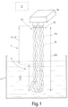
- the present invention relates to a meter and process for measuring the level of a liquid for example contained in a container.
- the meter and the related installation process, use and operation are particularly suitable for measuring the level of fuels or other flammable liquids with a high degree of safety against fires and detonations, for example for measuring the level of the fuel in the tanks of airplanes and other aircraft.
- the two plates are radially separated from one another by a cavity having annular-shaped cross sections.
- Such a cylindrical electric capacitor is arranged vertically in the tank so that as the level thereof changes the fuel rises more or less along the cavity that separates the two plates, thus changing the capacity of the capacitor.
- a purpose of the present invention is to avoid the aforementioned drawbacks and in particular to provide a meter and a process for measuring the level or the presence of a liquid in a tank or other container, which is more reliable and less dangerous than the devices and processes according to the state of the art.
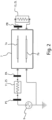
- the signal generator ( 9 ) is configured to generate a substantially periodic probing signal, with a frequency preferably comprised between 5-30 Megahertz.
- the liquid is selected from the following group: petrol, kerosene, diesel, a petroleum distillate, a mixture of hydrocarbons, water or an aqueous mixture, a fuel, liquid oxygen or hydrogen.
- US201113980451A relates to an apparatus for capacitive determining and/or monitoring at least of fill level of a medium in a container by measuring the phase shift.
- substantially equal to or almost equal to the impedance of the power and/or transmission line section 7 is meant to indicate that the sum of the impedances ZS and of the signal generator 9, and the impedance ZL of the second measurement load 11 are substantially equal to the impedance of the aforementioned power and/or transmission line section 7 with a tolerance equal to or less than +- 20% - and more preferably equal to or less than +- 10% - of the modulus and of the specific impedance of the power and/or transmission line section 7 considered above.
- the phase shift undergone by the probing signal is measured between a first PS and a second measuring point PA respectively upstream and downstream of the first measurement electrical load 11, for example immediately upstream and immediately downstream of the load 11.
- the meter 1 can comprise two synchronous samplers, not shown and for example of the per se known type, and configured to measure in a mutually synchronised manner the voltages or currents in the measurement points PS and PA of the electric line upstream and downstream of the first measurement electrical load 11.
- the phase shift undergone by the probing signal can be advantageously measured between two measurement points PA, PB arranged upstream and downstream of the section of the power and/or transmission line 7 dipped in the liquid for which it is wished to measure the level.
- Such points can for example be the second PA and the third measuring point PB of the line 7.
- the measured phase shifts of the probing signal between two different measurement points are influenced by the length L 2 of the section of the twisted pair - and more generally of the section of the power and/or transmission line 7- dipped in the liquid to be measured.
- the logic unit 3 can be advantageously configured to calculate the change in electrical capacity associated with the fringing field based on the phase shifts measured in the first PS and in the second measuring point PA.
- the logic unit 3 is configured for determining said electrical capacity, or in any case and more generally the aforementioned equivalent electrical capacity, determining, based on said phase shifts, one or more poles of the transfer function of at least part of the meter 1 and of the liquid in which the at least two probing conductors 7 a, 7 b are dipped.
- the logic unit 3 is programmed or in any case configured for determining such a capacity, determining the lowest frequency pole of such a transfer function, for example based on calculations and algorithms analogous to those that link the electrical capacity and the pole of a known RC filter.
- the logic unit 3 is configured to calculate the time of flight of the probing signal in the section of the power and/or transmission line comprised between the second PA and the third measuring point PB, again based on the phase shift that the probing signal undergoes between the measurement points PA and PB, for example with per se mathematical processes and algorithms used for example in current laser telemeters.
- the probing conductors 7 a, 7 b are coated with a material that is not very or not at all wettable, or their outer surface have been subjected to a suitable treatment that reduces or annulls the wettability, so as to prevent portions thereof from remaining wet even if out of the liquid, thus falsifying the measurement of the level.
- the electrical capacity depends linearly from the dielectric constant of the capacitor considered, whereas the time of flight depends on the square root of the dielectric constant of the medium considered; therefore the two determinations of the electrical capacity and of the time of flight are alternatives and independent from one another, one being able to be used to verify the other, correct possible errors or imprecisions of measurement or determine further parameters like for example the dielectric constant of the liquid for which it is wished to measure the level.
- the two measurements of the time of flight and of the pole or poles of the transfer function based on the phase shift of the probing signal can be carried out simultaneously or one after the other, a sufficiently short time after so as not to allow appreciable changes of the level of the liquid to be measured to occur.
- the two measurements of the time of flight and of the pole or poles of the transfer function based on the phase shift of the probing signal can be carried out with probing signals of different frequencies, for example with a probing signal at about 1 Megahertz for the first measurement and with a probing signal of about 10 megahertz for the second or vice-versa.
- the logic unit 3 or more generally the meter 1 is programmed or in any case configured to detect the phase shift of the signals acquired in the measurement points PS, PA, PB through suitable decimation or downsampling techniques.
- the logic unit 3 or more generally the meter 1 is programmed or in any case configured to detect the phase shift of the signals acquired in the measurement points PS, PA, PB for example through discrete Fourier transform and/or determining the phase and square component with a synchronous digital receiver, which carries out the multiplication of the sampled signal by two square signals (sine and cosine at the same frequency), to then evaluate the Fourier coefficients thereof.
- the logic unit 3 can be programmed or in any case configured to determine the phase shift between the voltages or currents detected in the measurement points PS, PA and/or PA, PB directly comparing signals having substantially the same frequency as the probing signal or in any case frequencies of the same order of magnitude, without frequency conversions, for example if the probing signal has relatively low frequencies, for example equal to or less than 10-20 Megahertz.
- the logic unit 3 or more generally the meter 1 can be provided with a frequency converter - for example a heterodyne converter - that transforms the signals measurement at the measurement points PS, PA, PB or others into lower frequency signals, making the phase shift with respect to the probing signal easier to measure.
- a frequency converter - for example a heterodyne converter - that transforms the signals measurement at the measurement points PS, PA, PB or others into lower frequency signals, making the phase shift with respect to the probing signal easier to measure.
- the frequency converter can be configured to reduce the signals measured at the measurement points PS, PA, PB or others into signals at a frequency equal to or less than 10 or 20 Megahertz.
- the frequency converter can comprise for example a mixer or sampler, for example of the per se known type.
- the logic unit 3 or more generally the meter 1 can be programmed or in any case configured to carry out a calibration procedure of the measurement of the level of the liquid through the time of flight along the power and/or transmission line 7.
- Such a calibration procedure can comprise for example the steps of detecting the time of flight along the line 7 when the sensitive body 5 is completely in air and when it is completely dipped in the liquid for which it is wished to measure the level.
- the measurement with sensitive body 5 completely dipped also provides a direct measurement of the properties of the liquid.
- the sensitive body 5 forms a prolongation that extends for a total length LCS preferably comprised between 0.1-10 metres, between 0.5-1 metre, between 0.2-0.5 metres or between 0.2-0.3 metres.
- measurers 1 capable of detecting the level of a liquid, such as a hydrocarbon-based fuel or water, with a resolution of one millimetre on a measurement range for example of 30-40 centimetres; such a measurement field is for example capable of covering the excursions of the level of the fuel in the tank of a helicopter.
Landscapes
- Physics & Mathematics (AREA)
- Engineering & Computer Science (AREA)
- Fluid Mechanics (AREA)
- General Physics & Mathematics (AREA)
- Power Engineering (AREA)
- Signal Processing (AREA)
- Electromagnetism (AREA)
- Thermal Sciences (AREA)
- Measurement Of Levels Of Liquids Or Fluent Solid Materials (AREA)
- Level Indicators Using A Float (AREA)
Claims (13)
- Messgerät (1) zur Messung des Niveaus einer Flüssigkeit, das eine oder mehrere elektrische Schaltungen umfasst, wobei die Schaltungen eine Logikeinheit (3), einen empfindlichen Körper (5, 5', 5", 5III , 5IV ) und einen Signalgenerator (9) umfassen, wobei:- der empfindliche Körper (5, 5', 5", 5III , 5IV ) eine Leistungs- und/oder Übertragungsleitung (7) umfasst, wobei die Leitung mindestens zwei Sondenleiter (7a, 7b) umfasst, wobei die Sondenleiter so konfiguriert sind, dass sie in die Flüssigkeit, deren Niveau gemessen werden soll, eingetaucht werden;- der Signalgenerator (9) so konfiguriert ist, dass er die Leistungs- und/oder Übertragungsleitung (7) mit einem Sondierungssignal versorgt;- die Logikeinheit (3) für die Durchführung der folgenden Schritte konfiguriert ist:- Bestimmen der Phasenverschiebung, die das Sondierungssignal zwischen mindestens zwei vorbestimmten Messpunkten (PS, PA, PB) des einen oder der mehreren elektrischen Schaltungen des Messgeräts (1) erfährt;- Bestimmen, auf der Grundlage der Phasenverschiebung, des Niveaus der vorbestimmten Flüssigkeit, in die der empfindliche Körper (5, 5', 5", 5III , 5IV ) mindestens teilweise und möglicherweise eingetaucht ist;wobei:- die Logikeinheit (3) so konfiguriert ist, dass sie auf der Grundlage der Phasenverschiebung eine elektrische Kapazität bestimmt, die mindestens einem Teil des Messgeräts (1) selbst und/oder der Flüssigkeit, in die die mindestens zwei Sondenleiter (7a, 7b) eingetaucht sind, entspricht und/oder von ihr beeinflusst wird;dadurch gekennzeichnet, dass:- der Zähler (1) mit einer ersten elektrischen Messlast (11) versehen ist, die von der mindestens einen Leistungsleitung (7) gespeist wird und mit einer vorbestimmten stromaufwärtigen Messimpedanz (ZS) versehen ist;- die Logikeinheit (3) so konfiguriert ist, dass sie die entsprechende elektrische Kapazität bestimmt, indem sie beide der folgenden Operationen ausführt:- auf der Grundlage einer ersten Phasenverschiebung, die zwischen einem ersten (PS) und einem zweiten Messpunkt (PA) jeweils stromaufwärts und stromabwärts der ersten elektrischen Messlast (11) gemessen wird, Bestimmen eines oder mehrerer Pole der Übertragungsfunktion von mindestens einem Teil des Messgeräts (1) und der Flüssigkeit, in die die mindestens zwei Sondenleiter (7a, 7b) eingetaucht sind;- auf der Grundlage einer zweiten Phasenverschiebung, die das Sondierungssignal zwischen einem zweiten (PA) und einem dritten Messpunkt (PB) erfährt, Bestimmen der Laufzeit des Sondierungssignals in dem Abschnitt der Leistungs- und/oder Übertragungsleitung, der zwischen dem zweiten (PA) und dem dritten Messpunkt (PB) liegt.
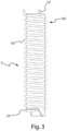
- Messgerät (1) nach Anspruch 1, wobei die mindestens zwei Sondenleiter (7a, 7b) elektrische Leiter sind, die sich nebeneinander entlang der Leistungs- und/oder Übertragungsleitung (7) erstrecken.
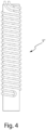
- Messgerät (1) nach einem oder mehreren der vorstehenden Ansprüche, wobei die mindestens zwei Sondenleiter (7a, 7b) elektrische Leiter sind, die umeinander und/oder um eine vorbestimmte Wickelachse verdrillt oder gewickelt sind, so dass sie im Wesentlichen ein verdrilltes Paar und/oder eine Spirale bilden.
- Messgerät (1) nach einem oder mehreren der vorstehenden Ansprüche, wobei die Logikeinheit (3) zum Erfassen oder jedenfalls zum Bestimmen der Phasenverschiebung, die das Sondierungssignal zwischen zwei Messpunkten (PS, PA, PB) eines Teils des einen oder der mehreren vom Signalgenerator (9) versorgten Stromkreise erfährt, und bei dem mindestens einer dieser Messpunkte (PB) entlang der Leistungs- und/oder Übertragungsleitung (7) oder stromabwärts davon liegt.
- Messgerät (1) nach einem oder mehreren der vorstehenden Ansprüche, wobei die Logikeinheit (3) programmiert oder in jedem Fall konfiguriert ist, um die Phasenverschiebung zu erfassen oder in jedem Fall zu bestimmen, die das Sondierungssignal zwischen zwei Messpunkten (PS, PA, PB) eines Teils der einen oder mehreren elektrischen Schaltungen, die von dem Signalgenerator (9) gespeist werden, erfährt, und wobei mindestens einer der Messpunkte (PS, PA) stromaufwärts von der Leistungs- und/oder Übertragungsleitung (7) liegt.
- Messgerät (1) nach einem oder mehreren der vorstehenden Ansprüche, wobei die Logikeinheit (3) so programmiert oder in jedem Fall so konfiguriert ist, dass sie die Phasenverschiebung erfasst oder in jedem Fall bestimmt, die das Sondierungssignal zwischen zwei Messpunkten (PS, PA) eines Teils des einen oder der mehreren elektrischen Schaltungen erfährt, die von dem Signalgenerator (9) versorgt werden, und wobei mindestens ein erster der Messpunkte (PS) stromaufwärts des Signalgenerators (9) liegt und mindestens ein zweiter solcher Messpunkte (PA) stromabwärts des Signalgenerators (9) und stromaufwärts der Leistungs- und/oder Übertragungsleitung (7) liegt.
- Messgerät (1) nach Anspruch 6, wobei die Logikeinheit (3) so programmiert oder jedenfalls konfiguriert ist, dass sie auf der Grundlage der Phasenverschiebung einen oder mehrere Pole der Übertragungsfunktion von mindestens einem Teil des Messgeräts (1) und der Flüssigkeit bestimmt, in die die mindestens zwei Sondenleiter (7a, 7b) eingetaucht sind.
- Messgerät (1) nach einem oder mehreren der vorstehenden Ansprüche, wobei die Logikeinheit (3) programmiert oder in jedem Fall konfiguriert ist, um die Phasenverschiebung zu erfassen oder in jedem Fall zu bestimmen, die das Sondierungssignal zwischen zwei Messpunkten (PA, PB) eines Teils des einen oder der mehreren elektrischen Schaltungen erfährt, die von dem Signalgenerator (9) versorgt werden, und wobei mindestens ein erster der Messpunkte (PA) stromabwärts des Signalgenerators (9) und stromaufwärts der Versorgungs- und/oder Übertragungsleitung (7) liegt und mindestens ein zweiter der Messpunkte (PB) stromabwärts der Leistungs- und/oder Übertragungsleitung (7) liegt.
- Messgerät (1) nach Anspruch 8, wobei die Logikeinheit (3) so programmiert oder jedenfalls konfiguriert ist, dass sie auf der Grundlage der Phasenverschiebung die Laufzeit des Sondierungssignals in einem vorbestimmten Teil der Übertragungs- und/oder Leistungsleitung (7), beispielsweise in dem Abschnitt zwischen dem ersten (PA) und dem zweiten Messpunkt (PB), bestimmt.
- Messgerät (1) nach einem oder mehreren der vorstehenden Ansprüche, wobei die Logikeinheit (3) so programmiert oder auf jeden Fall so konfiguriert ist, dass sie die Phasenverschiebung auf der Grundlage von mindestens 2000 Spannungs- oder Stromabtastwerten, die in den mindestens zwei vorbestimmten Messpunkten (PS, PA, PB) erfasst werden, erfasst oder auf jeden Fall bestimmt.
- Messgerät (1) nach einem oder mehreren der vorstehenden Ansprüche, wobei die Logikeinheit (3) so konfiguriert ist, dass sie eine Bestimmung des vorbestimmten Flüssigkeitsniveaus mit der Bestimmung der erfassten Laufzeit verknüpft.
- Verfahren zur Messung des Niveaus eines Flüssigkeitsbades, umfassend die folgenden Schritte:S13.1) Bereitstellen eines Messgeräts (1), das einen oder mehrere elektrische Schaltungen umfasst, wobei die Schaltungen einen empfindlichen Körper (5, 5', 5", 5III , 5IV ) umfassen, wobei der empfindliche Körper eine Leistungs- und/oder Übertragungsleitung (7) umfasst, wobei die Leitung mindestens zwei Sondenleiter (7a, 7b) umfasst, wobei das Messgerät (1) ferner eine erste elektrische Messlast (11) umfasst, die von der mindestens einen Leistungsleitung (7) gespeist wird und mit einer vorbestimmten stromaufwärts liegenden Messimpedanz (ZS) versehen ist;S13.2) mindestens teilweises Eintauchen des empfindlichen Körpers in das Flüssigkeitsbad;S13.3) Versorgen der Leistungs- und/oder Übertragungsleitung (7) mit einem Sondierungssignal;S13.4) Bestimmen der Phasenverschiebung, die das Sondierungssignal zwischen mindestens zwei vorbestimmten Messpunkten (PS, PA, PB) des einen oder der mehreren elektrischen Schaltungen des Messgeräts (1) erfährt;S13.5) Bestimmen, auf der Grundlage der Phasenverschiebung, einer elektrischen Kapazität, die mindestens einem Teil des Messgeräts (1) selbst und der Flüssigkeit, in die die mindestens zwei Sondenleiter (7a, 7b) eingetaucht sind, entspricht und/oder von ihnen beeinflusst wird;S13.6) Bestimmen des Niveaus des Flüssigkeitsbades auf der Grundlage der Phasenverschiebung;dadurch gekennzeichnet, dass die entsprechende elektrische Kapazität durch die Durchführung der beiden folgenden Vorgänge bestimmt wird:- auf der Grundlage einer ersten Phasenverschiebung, die zwischen einem ersten (PS) und einem zweiten Messpunkt (PA) jeweils stromaufwärts und stromabwärts der ersten elektrischen Messlast (11) gemessen wird, Bestimmen eines oder mehrerer Pole der Übertragungsfunktion von mindestens einem Teil des Messgeräts (1) und der Flüssigkeit, in die die mindestens zwei Sondenleiter (7a, 7b) eingetaucht sind;- auf der Grundlage einer zweiten Phasenverschiebung, die das Sondierungssignal zwischen einem zweiten (PA) und einem dritten Messpunkt (PB) erfährt, Bestimmen der Laufzeit des Sondierungssignals in dem Abschnitt der Leistungs- und/oder Übertragungsleitung, der zwischen dem zweiten (PA) und dem dritten Messpunkt (PB) liegt.
- Verfahren nach Anspruch 12, wobei der empfindliche Körper (5, 5', 5", 5III , 5IV ) eine im Wesentlichen längliche Gesamtform aufweist, und das Verfahren den Schritt des Einsetzens des empfindlichen Körpers in einen Behälter (S), der für die Aufnahme der Flüssigkeit konfiguriert ist, oder des Verschließens des Behälters (S) mit einer im Wesentlichen vertikalen Ausrichtung oder auf jeden Fall so, dass er sich im Wesentlichen von oben nach unten erstreckt, umfasst.
Applications Claiming Priority (1)
| Application Number | Priority Date | Filing Date | Title |
|---|---|---|---|
| IT102019000014043A IT201900014043A1 (it) | 2019-08-05 | 2019-08-05 | Misuratore e procedimento per misurare il livello di un liquido. |
Publications (3)
| Publication Number | Publication Date |
|---|---|
| EP3772636A1 EP3772636A1 (de) | 2021-02-10 |
| EP3772636C0 EP3772636C0 (de) | 2025-06-25 |
| EP3772636B1 true EP3772636B1 (de) | 2025-06-25 |
Family
ID=69173140
Family Applications (1)
| Application Number | Title | Priority Date | Filing Date |
|---|---|---|---|
| EP20189345.0A Active EP3772636B1 (de) | 2019-08-05 | 2020-08-04 | Messgerät und verfahren zur messung des niveaus einer flüssigkeit |
Country Status (5)
| Country | Link |
|---|---|
| US (1) | US20210041282A1 (de) |
| EP (1) | EP3772636B1 (de) |
| ES (1) | ES3037192T3 (de) |
| IT (1) | IT201900014043A1 (de) |
| PL (1) | PL3772636T3 (de) |
Families Citing this family (1)
| Publication number | Priority date | Publication date | Assignee | Title |
|---|---|---|---|---|
| DK202330396A1 (en) * | 2023-12-13 | 2025-07-01 | Typhon Tech Aps | Capacitive sensor |
Family Cites Families (2)
| Publication number | Priority date | Publication date | Assignee | Title |
|---|---|---|---|---|
| US7340951B2 (en) * | 2005-11-04 | 2008-03-11 | David S. Nyce | Distributed impedance sensor |
| DE102011003158A1 (de) * | 2011-01-26 | 2012-07-26 | Endress + Hauser Gmbh + Co. Kg | Vorrichtung und Verfahren zur kapazitiven Füllstandsmessung |
-
2019
- 2019-08-05 IT IT102019000014043A patent/IT201900014043A1/it unknown
-
2020
- 2020-08-04 ES ES20189345T patent/ES3037192T3/es active Active
- 2020-08-04 PL PL20189345.0T patent/PL3772636T3/pl unknown
- 2020-08-04 EP EP20189345.0A patent/EP3772636B1/de active Active
- 2020-08-07 US US16/988,063 patent/US20210041282A1/en not_active Abandoned
Also Published As
| Publication number | Publication date |
|---|---|
| EP3772636C0 (de) | 2025-06-25 |
| IT201900014043A1 (it) | 2021-02-05 |
| PL3772636T3 (pl) | 2025-09-22 |
| ES3037192T3 (en) | 2025-09-30 |
| EP3772636A1 (de) | 2021-02-10 |
| US20210041282A1 (en) | 2021-02-11 |
Similar Documents
| Publication | Publication Date | Title |
|---|---|---|
| KR101285460B1 (ko) | 용량성 액체 레벨 센서 | |
| EP2414792B1 (de) | Kraftstoffmesssystem mit einer digitalen kraftstoffmesssonde | |
| US5051921A (en) | Method and apparatus for detecting liquid composition and actual liquid level | |
| US3862571A (en) | Multielectrode capacitive liquid level sensing system | |
| EP3002594B1 (de) | Spannungsmessvorrichtung | |
| US7010985B2 (en) | Gauge for measuring fuel level in a tank, and a system for measuring the weight of fuel in the tank | |
| JPH0217299Y2 (de) | ||
| US8196465B2 (en) | Apparatus for ascertaining and monitoring fill level of a medium in a container | |
| US20050122122A1 (en) | Voltage sensor and dielectric material | |
| CN100439880C (zh) | 用于电容式料位测量的测量仪表的制造侧标定以及相应的测量仪表 | |
| EP3772636B1 (de) | Messgerät und verfahren zur messung des niveaus einer flüssigkeit | |
| WO2010077893A1 (en) | Liquid level sensor having a reference capacitance | |
| US12270695B2 (en) | Capacitive fuel gaging system with resistive elements | |
| CA2672794C (en) | Apparatus for determining and/or monitoring a process variable | |
| EP3415929B1 (de) | Elektrisches zubehör mit einem messelement der spannung an einem kabel | |
| US8434211B2 (en) | Method for manufacturing a capacitive measuring apparatus | |
| RU240591U1 (ru) | Высоковольтный измерительный преобразователь напряжения | |
| RU111680U1 (ru) | Устройство для измерения напряжения на высоковольтных линиях электропередач | |
| RU210982U1 (ru) | Высоковольтный измерительный преобразователь напряжения | |
| RU2337327C2 (ru) | Устройство измерения уровней границ раздела сред и способ измерения уровней границ раздела сред | |
| RU2758995C1 (ru) | Изобретения, относящиеся к емкостному датчику уровня границы раздела сред | |
| RU85641U1 (ru) | Емкостной измеритель уровня жидкости | |
| GB2549482A (en) | Charge measurement apparatus and method | |
| JP7071733B2 (ja) | センサ | |
| RU64360U1 (ru) | Устройство измерения уровней границ раздела сред |
Legal Events
| Date | Code | Title | Description |
|---|---|---|---|
| PUAI | Public reference made under article 153(3) epc to a published international application that has entered the european phase |
Free format text: ORIGINAL CODE: 0009012 |
|
| STAA | Information on the status of an ep patent application or granted ep patent |
Free format text: STATUS: THE APPLICATION HAS BEEN PUBLISHED |
|
| AK | Designated contracting states |
Kind code of ref document: A1 Designated state(s): AL AT BE BG CH CY CZ DE DK EE ES FI FR GB GR HR HU IE IS IT LI LT LU LV MC MK MT NL NO PL PT RO RS SE SI SK SM TR |
|
| AX | Request for extension of the european patent |
Extension state: BA ME |
|
| STAA | Information on the status of an ep patent application or granted ep patent |
Free format text: STATUS: REQUEST FOR EXAMINATION WAS MADE |
|
| 17P | Request for examination filed |
Effective date: 20210802 |
|
| RBV | Designated contracting states (corrected) |
Designated state(s): AL AT BE BG CH CY CZ DE DK EE ES FI FR GB GR HR HU IE IS IT LI LT LU LV MC MK MT NL NO PL PT RO RS SE SI SK SM TR |
|
| STAA | Information on the status of an ep patent application or granted ep patent |
Free format text: STATUS: EXAMINATION IS IN PROGRESS |
|
| 17Q | First examination report despatched |
Effective date: 20230220 |
|
| GRAP | Despatch of communication of intention to grant a patent |
Free format text: ORIGINAL CODE: EPIDOSNIGR1 |
|
| STAA | Information on the status of an ep patent application or granted ep patent |
Free format text: STATUS: GRANT OF PATENT IS INTENDED |
|
| RIC1 | Information provided on ipc code assigned before grant |
Ipc: G01F 25/00 20060101ALN20250127BHEP Ipc: G01F 23/80 20220101ALI20250127BHEP Ipc: G01F 23/263 20220101ALI20250127BHEP Ipc: G01F 23/26 20060101ALI20250127BHEP Ipc: G01F 23/00 20060101AFI20250127BHEP |
|
| INTG | Intention to grant announced |
Effective date: 20250207 |
|
| GRAS | Grant fee paid |
Free format text: ORIGINAL CODE: EPIDOSNIGR3 |
|
| RAP1 | Party data changed (applicant data changed or rights of an application transferred) |
Owner name: LOGIC S.P.A. |
|
| GRAA | (expected) grant |
Free format text: ORIGINAL CODE: 0009210 |
|
| STAA | Information on the status of an ep patent application or granted ep patent |
Free format text: STATUS: THE PATENT HAS BEEN GRANTED |
|
| AK | Designated contracting states |
Kind code of ref document: B1 Designated state(s): AL AT BE BG CH CY CZ DE DK EE ES FI FR GB GR HR HU IE IS IT LI LT LU LV MC MK MT NL NO PL PT RO RS SE SI SK SM TR |
|
| REG | Reference to a national code |
Ref country code: GB Ref legal event code: FG4D |
|
| REG | Reference to a national code |
Ref country code: CH Ref legal event code: EP |
|
| REG | Reference to a national code |
Ref country code: CH Ref legal event code: EP |
|
| REG | Reference to a national code |
Ref country code: IE Ref legal event code: FG4D |
|
| REG | Reference to a national code |
Ref country code: DE Ref legal event code: R096 Ref document number: 602020053195 Country of ref document: DE |
|
| U01 | Request for unitary effect filed |
Effective date: 20250703 |
|
| U07 | Unitary effect registered |
Designated state(s): AT BE BG DE DK EE FI FR IT LT LU LV MT NL PT RO SE SI Effective date: 20250710 |
|
| U20 | Renewal fee for the european patent with unitary effect paid |
Year of fee payment: 6 Effective date: 20250814 |
|
| REG | Reference to a national code |
Ref country code: ES Ref legal event code: FG2A Ref document number: 3037192 Country of ref document: ES Kind code of ref document: T3 Effective date: 20250930 |
|
| PGFP | Annual fee paid to national office [announced via postgrant information from national office to epo] |
Ref country code: ES Payment date: 20250905 Year of fee payment: 6 |
|
| PG25 | Lapsed in a contracting state [announced via postgrant information from national office to epo] |
Ref country code: GR Free format text: LAPSE BECAUSE OF FAILURE TO SUBMIT A TRANSLATION OF THE DESCRIPTION OR TO PAY THE FEE WITHIN THE PRESCRIBED TIME-LIMIT Effective date: 20250926 Ref country code: NO Free format text: LAPSE BECAUSE OF FAILURE TO SUBMIT A TRANSLATION OF THE DESCRIPTION OR TO PAY THE FEE WITHIN THE PRESCRIBED TIME-LIMIT Effective date: 20250925 |
|
| PGFP | Annual fee paid to national office [announced via postgrant information from national office to epo] |
Ref country code: TR Payment date: 20250730 Year of fee payment: 6 Ref country code: PL Payment date: 20250731 Year of fee payment: 6 |
|
| PGFP | Annual fee paid to national office [announced via postgrant information from national office to epo] |
Ref country code: GB Payment date: 20250731 Year of fee payment: 6 |
|
| PG25 | Lapsed in a contracting state [announced via postgrant information from national office to epo] |
Ref country code: HR Free format text: LAPSE BECAUSE OF FAILURE TO SUBMIT A TRANSLATION OF THE DESCRIPTION OR TO PAY THE FEE WITHIN THE PRESCRIBED TIME-LIMIT Effective date: 20250625 |
|
| PG25 | Lapsed in a contracting state [announced via postgrant information from national office to epo] |
Ref country code: RS Free format text: LAPSE BECAUSE OF FAILURE TO SUBMIT A TRANSLATION OF THE DESCRIPTION OR TO PAY THE FEE WITHIN THE PRESCRIBED TIME-LIMIT Effective date: 20250925 |
|
| PGFP | Annual fee paid to national office [announced via postgrant information from national office to epo] |
Ref country code: CZ Payment date: 20250818 Year of fee payment: 6 |
|
| PG25 | Lapsed in a contracting state [announced via postgrant information from national office to epo] |
Ref country code: IS Free format text: LAPSE BECAUSE OF FAILURE TO SUBMIT A TRANSLATION OF THE DESCRIPTION OR TO PAY THE FEE WITHIN THE PRESCRIBED TIME-LIMIT Effective date: 20251025 |
|
| PG25 | Lapsed in a contracting state [announced via postgrant information from national office to epo] |
Ref country code: SM Free format text: LAPSE BECAUSE OF FAILURE TO SUBMIT A TRANSLATION OF THE DESCRIPTION OR TO PAY THE FEE WITHIN THE PRESCRIBED TIME-LIMIT Effective date: 20250625 |
|
| PG25 | Lapsed in a contracting state [announced via postgrant information from national office to epo] |
Ref country code: SK Free format text: LAPSE BECAUSE OF FAILURE TO SUBMIT A TRANSLATION OF THE DESCRIPTION OR TO PAY THE FEE WITHIN THE PRESCRIBED TIME-LIMIT Effective date: 20250625 |
|
| REG | Reference to a national code |
Ref country code: CH Ref legal event code: H13 Free format text: ST27 STATUS EVENT CODE: U-0-0-H10-H13 (AS PROVIDED BY THE NATIONAL OFFICE) Effective date: 20260324 |
|
| PG25 | Lapsed in a contracting state [announced via postgrant information from national office to epo] |
Ref country code: MC Free format text: LAPSE BECAUSE OF FAILURE TO SUBMIT A TRANSLATION OF THE DESCRIPTION OR TO PAY THE FEE WITHIN THE PRESCRIBED TIME-LIMIT Effective date: 20250625 |
|
| PG25 | Lapsed in a contracting state [announced via postgrant information from national office to epo] |
Ref country code: CH Free format text: LAPSE BECAUSE OF NON-PAYMENT OF DUE FEES Effective date: 20250831 |
|
| PLBE | No opposition filed within time limit |
Free format text: ORIGINAL CODE: 0009261 |
|
| STAA | Information on the status of an ep patent application or granted ep patent |
Free format text: STATUS: NO OPPOSITION FILED WITHIN TIME LIMIT |