EP3772631B1 - Appareil pour chargement de chargeurs de munitions - Google Patents
Appareil pour chargement de chargeurs de munitions Download PDFInfo
- Publication number
- EP3772631B1 EP3772631B1 EP20190307.7A EP20190307A EP3772631B1 EP 3772631 B1 EP3772631 B1 EP 3772631B1 EP 20190307 A EP20190307 A EP 20190307A EP 3772631 B1 EP3772631 B1 EP 3772631B1
- Authority
- EP
- European Patent Office
- Prior art keywords
- ammunition
- magazine
- housing
- main housing
- slide housing
- Prior art date
- Legal status (The legal status is an assumption and is not a legal conclusion. Google has not performed a legal analysis and makes no representation as to the accuracy of the status listed.)
- Active
Links
Images


Classifications
-
- F—MECHANICAL ENGINEERING; LIGHTING; HEATING; WEAPONS; BLASTING
- F41—WEAPONS
- F41A—FUNCTIONAL FEATURES OR DETAILS COMMON TO BOTH SMALLARMS AND ORDNANCE, e.g. CANNONS; MOUNTINGS FOR SMALLARMS OR ORDNANCE
- F41A9/00—Feeding or loading of ammunition; Magazines; Guiding means for the extracting of cartridges
- F41A9/82—Reloading or unloading of magazines
- F41A9/83—Apparatus or tools for reloading magazines with unbelted ammunition, e.g. cartridge clips
Definitions
- the invention relates generally to firearms and more specifically to apparatus and method for loading magazines in an efficient manner with limited contact between the user and the rounds.
- US9574836 B1 relates to a firearm magazine loader, associated components, and methods of use.
- US10132582 B1 relates to a reloading system and method for reloading cartridges into an ammunition magazine.
- US9995548 B1 relates to a reloading system and method for reloading cartridges into a removable ammunition magazine of a gun.
- a device for loading ammunition in a magazine having a slide housing, that houses the ammunition in the appropriate amount for each magazine, holds each round by its rim to prevent contact between the lead portion of the bullet and the device, and reduces friction between the device and the rounds, a main housing, which holds the rounds in position within the slide housing by the use of retention caps and readies them for loading, and a magazine holder, that depresses the magazine button to allow for accelerated loading of a full magazine at once.
- Another advantage is the user no longer having to depress the magazine button manually because depressing the button manually for an extended period of time can lead to finger fatigue or even blisters. This also allows the ammunition to easily slide into the magazine without any mechanical force because the rounds slide into the open magazine using gravity. Another advantage is the time saved by using this device. In an example, the device allows for five magazines at a total of fifty round capacity be loaded within thirty seconds and then allowing the loader to be ready to be used again within a ten second window. Overall, this allows the user to have more time firing the firearm instead of time spent tediously loading each magazine.
- the apparatus for loading magazines can also be used to store ammunition in a compact manner. Not properly stored ammunition can lead to the bullets being damaged or in the worst case can lead to them discharging and causing a chain reaction in the container they are being stored in. Furthermore, firearms enthusiasts typically keep bullets loose inside their housings or loose for manual loading on the range. Thus, another advantage is that the ammunition can be stored safely within the loading apparatus.
- the loading apparatus when filled, can be stood on by a grown man weighing in excess of 100kg and the container will still exert no pressure to the rounds inside, which means the round will not unintentionally discharge.
- Another advantage is its compact size due to the magazine housing being detachable. The detachability of the magazine holder also makes the apparatus more universal to the possibility of different magazine shapes.
- a magazine ammunition loading apparatus comprising:
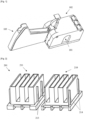
- FIG. 1 illustrates the perspective view of a device for loading ammunition in a magazine showing three loading components namely the slide housing 101, main housing 102, and magazine holder 103, according to an aspect. As it will be described in more detail hereinafter, these three loading components cooperate to expediently and safely load a magazine.
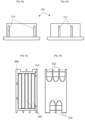
- FIG. 2 illustrates the left and right perspective views of a slide housing 201, according to an aspect.
- the slide housing has two sides 210 and 211 with ammunition exits to allow the bullets to leave the slide housing as shown in FIG. 3d-3f , and as it will be described when referring to FIG. 3d-3f .
- the male thin-span key protrusions 213 and male wide-span key protrusions 214 allow the slide housing 201 to engage with the main housing 102, as it will be described when referring to FIG. 9c .
- magnets may be used to engage the slide housing 201 with the main housing 102 and the magnets may be made of neodymium because of their thin structure and may be flush with the main housing 102.
- magnets could fail and thus could pose a hazard to the user by accidently opening the delivery assembly.
- FIG. 3a illustrates a back view of the slide housing 301, which as shown has a set of exterior male wide-span key protrusions 314, according to an aspect.
- the corresponding configuration, specifically the female keyways 529 on the main housing 102 allow for the slide housing 301 and the main housing 102 to be orientated only in the correct alignment, which is as shown in FIG. 9c , and as it will be described when referring to FIG. 9c .
- FIG. 3b illustrates a front view of the slide housing 301, which as shown has an exterior set of male thin-span key protrusions 313, according to an aspect.
- the corresponding configurations, specifically female keyways 523 on the main housing 102 allow for the slide housing 301 and the main housing 102 to be orientated only in the correct alignment, which is shown in FIG. 9c , and it will be described more when referring to FIG. 9c .
- FIG. 3c illustrates a top view of the slide housing 301, which as shown is formed by a zig zag pattern 315 and rails 306 creating a channel 307 for containing the ammunition, and both a set of exterior wide-span 314 and thin-span 313 protrusions, according to an aspect.
- FIG. 3d illustrates a bottom view of the slide housing, according to an aspect.
- the slide housing 301 also includes hook points, or notches 316 for the retention caps to engage the slide housing 301 to the main housing 102. This engagement between the slide housing 301 and the main housing 102 ensures a secure connection via the retention caps being able to grip the slide housing notch 316 when in the locked position.
- These notches 316 are aligned with each channel ammunition exit 307 to allow the retention caps to operationally engage with the slide housing 301, thus providing a locked engagement and alignment with the slide housing 301 and the main housing 102.
- the retention caps may engage with the slide housing notches 316 which act as a mechanical lock, to provide the secure connection between the slide housing 301 and the main housing 102.
- the notches 316 allow for the delivery assembly 981 to be securely engaged at all times when a minimum of one retention cap may be in the closed position.
- the slide housing 301 may have grooves for the finger of the user to easily and ergonomically open the retention caps from the bottom of the slide housing 301.
- FIG. 3e illustrates a right side view of the slide housing 301, which show the bullet channels 307 and the three-ammunition openings 311 configuration, according to an aspect.
- FIG. 3f illustrates a left side view of the slide housing 301, which show the bullet channels 307 and the two-ammunition opening 310 configuration, according to an aspect.
- each channel 307 alternates its ammunition exits 310, 311 from the immediately adjacent channel 307, such that two of the ammunition exits depicted as 310 are on one side and the remaining three of the ammunition exits depicted as 311 are on the opposite side of the slide housing 301.
- FIG. 3f also show the bottom plate 305, which allows the slide housing 301 to be easily removed from the main housing 102 by using the thumb recess 404, which is as shown in FIG. 4 , and as it will be described when referring to FIG. 4 .
- the channels 307 allow each row of ammunition to be completely independent within the system, such that to slide out of the channels 307 without affecting the ammunition within the other channels 307.
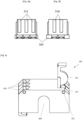
- FIG. 4 illustrates the perspective view of a main housing 402, which is an exterior container with two or three retention caps 420 on each side respectively along with a cutout (thumb recess) 404 for access to the interior components on the front and back sides, according to an aspect.
- the main housing 402 allows for the ammunition to be easily loaded from the manufacturers box to the housing itself as described below when referring to FIG. 9a .
- the main housing 402 attaches to the slide housing 101 by the interior keyholes, which is as shown in FIG. 5e , and as it will be described when referring to FIG. 5e .
- the main housing 402 contains retention caps 420 which allow for the ammunition to leave the fully assembled unit only when the user desires.
- the retention caps 420 also contain a protrusion 421 for snuggly fitting into the exterior ammunition opening, which is as shown in FIG. 6b , and as it will be described when referring to FIG. 6b , further ensuring the rounds stay within the housing.
- a hinge pin 422 may be used to pass through each retention cap 420 and the main housing 402 on each side of the main housing 402.
- the cutout, or thumb recess 404 may be used for holding the manufacturer's ammunition retention casing in place during the process of loading the bullets into the main housing 402, which is as shown in FIG. 9a , and as it will be described when referring to FIG. 9a .
- the main housing 402 also contains a retention cap cutout 457.
- the retention cap cutout 457 is the hollowed-out portion on the main housing 402 underneath each retention cap 420.
- FIG. 5a illustrates a left side view of the main housing 102 with the three-ammunition opening 510 configuration, where each ammunition opening is comprised of a slot 526, being the larger gap for the length of the ammunition to pass through, and the rail 525, being the top portion where the rim of the bullet would rest on for the bullet to pass through, according to an aspect.
- FIG. 5c illustrates a right side view of the main housing 102 with the three-ammunition opening 511 configuration, where each ammunition opening is comprised of a slot 526, being the larger gap for the length of the ammunition to pass through, and the rail 525, being the top portion where the rim of the bullet would rest on for the bullet to pass through, according to an aspect.
- a single ammunition opening 524 is shown, this shape allows the bullet to be able to slide through the space without a large amount of contact on the component.
- the rail 525 shows the segment for which the ammunition rests on to allow the minimum contact.
- the slot 526 is the larger empty space that the remaining casing of the bullet would pass through, this shape is bigger than the actual casing to limit the amount of contact, which further decreases fouling along with friction between the bullet and the housing allowing for better sliding into the magazine.
- the limited contact between the bullet, channel 307, and ammunition opening 524 means less lead particles being transferred, which decreases risk of particles becoming in contact with the user's skin.
- FIG. 5b illustrates a front view of the main housing 102 with both sides having a set of hinge pin holes 522 along with a cutout 504 for access to the interior components, according to an aspect.
- the hinge pin holes allow for the retention caps 420 to have the ability to be moved from the closed to open position manually.
- FIG. 5d illustrates a top view of the main housing 402 showing the female coupling element 527, according to an aspect.
- the female coupling element 527 such as a groove or slot, have a complementary male coupling element configuration on the magazine holder 103 allowing for the magazine holder 103 to be slid into the main housing 102.
- FIG. 5e illustrates the bottom view of the main housing 102 showing the set of female thin-span keyways 523 and the set of female wide-span keyways 529, and female coupling element 527, according to an aspect.
- the two different female keyway configurations permit only correct alignment for inserting the slide housing 101 into the main housing 402.
- FIG. 5f illustrates a perspective view of the main housing 102, more specifically female coupling element 527 for securely connecting the main housing 402 to the magazine holder 103 along with the hinge pin holes 522 for securing the retention caps 420 to the main housing 402, according to an aspect.
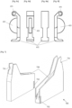
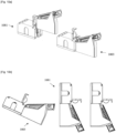
- FIGs. 6a - 6f illustrate multiple views of the front of a retention cap 620, further showing a lifting lip 652, a protrusion 621, and a hinge pin hole 651, according to an aspect.
- the retention caps 620 prevent the rounds from exiting the main housing 102 and slide housing 101 assembly, or delivery assembly, prior to the user being ready.
- the protrusions 621 retain the ammunition within the delivery assembly.
- the protrusion 621 on the retention caps 620 hold the first round within the slide housing 101 and away from the shear point of where the slide housing 101 meets the main housing 102.
- the protrusion 621 also limits rattling within the apparatus when holding the first round inside the delivery assembly because the protrusion 621 eliminates the extra space that would allow the rounds to move around in the channel 307.
- the lifting lip 652 also helps provide a secure connection between the main housing 102 and the slide housing 101.
- the lifting lip 652 allows for this strong connection because the retention cap 620 swings from the open, or unlocked, position, into the closed, or locked, position, the close position being when the lifting lip 652 is engaged within the slide housing notch.
- the angle of the top slanted edge of the retention cap 620 may be at 45 degrees to ensure the retention caps 620 sits flush on a flat surface, which also may keep the lifting lip 652 from obstructing the addition of a new box of rounds to the main housing 102.
- the retention caps 620 lock the delivery assembly 981 into a secured position to deter the slide housing 101 and main housing 102 from separating when not desired by the user. It should be noted that the retention caps 620 have a dual function that of securely locking the delivery assembly 981 in place and holding the ammunition within the channels. The retention caps 620 lock the delivery assembly 981 together such as to prevent an accidental opening of the delivery assembly 981, which may lead to the ammunition leaving the delivery assembly 981 and miss firing. In an example, the retention caps 620 may engage with the slide housing 101 via a mechanical lock, such as by a snap-on lock, as known in the art.
- FIG. 7 illustrates the perspective view of a magazine holder 703, containing a groove 730 running its length for the magazine to be placed in, a circular indent or indentation 731 for the magazine button to be depressed by, and a male coupling element 732 for attaching the magazine holder 703 to the main housing 102, according to an aspect.
- the magazine holder 703 attaches to the main housing 102 and the slide housing 101 by the male coupling element 732, which ensures a quality connection between the parts of the system and for the bullets to be able to easily slide into the magazine.
- the magazine holder 730 is set at the optimal angle for the magazine and the main housing ammunition openings to be in line for the ammunition to easily flow from the main housing 102 to the magazine.
- an optimal angle for the magazine holder may be twenty-five degrees.
- This groove 730 allows for the magazine to be held within the indentation snuggly so it remains stationary during the loading process.
- the groove 730 holds the magazine in place while the ammunition is slid into the magazine's opening and the button recess 731 allows for the magazine's button to be held in place for the entire loading process.
- the magazine holder can be used with Ruger MK3 and MK4 pistol magazines because of the standard shape.
- FIG. 8a illustrates a front view of a magazine holder device 803 further showing the groove 830 for holding the magazine and showing the outline of curvature 833 on the magazine holder for transferring rounds from the main housing 102 to the magazine on the magazine holder 803, according to an aspect.
- This curvature 833 does not occur the entire width of the magazine holder because it allows for just the bullet to be lifted slightly to present it to the magazine opening with as little resistance as possible.
- FIG. 8b illustrates a right side view of a magazine holder device 803 further showing the mating groove 832 for holding the magazine holder 803 to the main housing 102 and the circular indent 831 for depressing the magazine's button, according to an aspect.
- FIG. 8c illustrates a back view of a magazine holder 803 further showing the groove 830 for holding the magazine, according to an aspect.
- FIG. 8d illustrates a left side view of a magazine holder device further showing the mating groove 832 for holding the magazine holder 803 to the main housing 102, according to an aspect.
- FIG. 8e illustrates a bottom view of a magazine holder device further showing the mating groove 832, for holding the magazine holder 803 to main housing 102.
- FIG. 8f illustrates a top view of a magazine holder device 803, further showing the curvature 833 on the magazine holder groove 830 for transferring rounds from the main housing 102 to the magazine on the magazine holder 803, according to an aspect.
- FIGs. 9a-10b depict the process of assembling and filling the apparatus for loading a magazine.
- FIG. 9a indicates that the first step of using the apparatus for loading ammunition into a magazine, may be to combine rounds and main housing 902, which is shown in FIG. 9a . This may be done by removing the ammunition from the manufacturer's box and placing the main housing deliver box 902 over the rounds that are still contained in the manufacturer's retention packaging. The main housing 902 and rounds are then flipped, and the plastic retention packing is removed. This allows the rounds to be freestanding in the main housing.
- the angle of the top slanted edge of the retention cap 620 may be at 45 degrees to ensure the retention caps 620 sits flush with the main housing 902 on a flat surface, which also may keep the lifting lip 652 from obstructing the addition of a new box of rounds to the main housing 102.
- the user would insert a magazine into the magazine holder 903 by fitting the magazine into the top groove with the magazine button in line with the circular indentation on the magazine holder 903 and pushing the magazine in place, as shown in FIG. 9b .
- the user would insert the slide housing 901 into the main housing 902 in the correct orientation.
- the slide housing 901 may only be inserted, engaged with each other, in the correct orientation due to the keyway and protrusion shapes on both the slide housing 901 and the main housing 902 demonstrated in FIG. 9c .
- the slide housing 901 and main housing delivery box 902 may be engaged if the orientation of the two parts are correct.
- the proper engagement is allowed by the correct alignment of the protrusions and keyholes.
- the previously described wide-span protrusions will align with the wide-span keyholes, while the thin-span protrusions will align with the thin-span keyholes.
- the two orientation patterns allow for the main housing 902 and slide housing 901 to engage in the proper orientation, allowing for the ammunition exits and ammunition openings to also always be aligned.
- a delivery assembly 981 is formed by the slide housing 901 and the main housing 902 becoming engaged with each other, in which the interior walls of the main housing 902 and the exterior walls of the slide housing 901, or mating surfaces, come into contact to form a secure connection with the assistance of the keyholes, protrusions, and retention caps.
- the retention caps may move to the closed position and lock onto the slide housing 901.
- the engagement of the retention caps onto the slide housing 901 allow for a sturdy connection between the main housing 902 and the slide housing 901.
- the shape of the retention cap allows for the retention cap to be in the closed position without disturbing the surface the rounds are sitting on within the main housing 902.
- the retention caps do not to lift the main housing 902 due to the retention cap moving away from the flat surface in which the delivery assembly 981 is resting on.
- This feature further ensures the proper alignment between the slide housing 901 and main housing 902, which allows the bullets to slide into the magazine with the precision necessary.
- This two-part assembly of the slide housing 901 and the main housing 902, the delivery assembly 981, can also be used to store ammunition in a compact manner, while also storing the unused bullets safely.
- the delivery assembly 981 could also be used for temporarily storing, or containing, the ammunition.
- the loading apparatus when filled, can be stood on by a grown man weighing in excess of 100kg and the container will still exert no pressure to the rounds inside, which means the round will not unintentionally discharge.
- FIG. 10a illustrates a perspective view of the delivery assembly 1081 being combined with the magazine holder 1003 and empty magazine, according to an aspect.
- FIG. 10b illustrates a side view of the entire system being rotated to allow for the ammunition to slide into the empty magazine, according to an aspect.
- the main housing retention cap can be lifted and the slot side of the magazine holder, with the magazine inserted, would be slid into the delivery assembly 1081 shown in FIG. 10a .
- the magazine holder's hook and male coupling element would slide into the notch on the slide housing 1001 and female coupling element on the main housing 1002 to operationally engage the components.
- the user With apparatus fully assembled, the user would turn the system for the rounds to exit the main housing 1002 into the empty magazine. In an example, the user would turn the apparatus ninety degrees to allow the ammunition to slide from the delivery assembly into the magazine.
- the device allows the loading of five magazines, each magazine having a ten-round capacity, within thirty seconds and then allowing the loader to be ready to be used again within a ten-second window.
Landscapes
- Engineering & Computer Science (AREA)
- General Engineering & Computer Science (AREA)
- Packaging Of Annular Or Rod-Shaped Articles, Wearing Apparel, Cassettes, Or The Like (AREA)
Claims (15)
- Appareil de chargement de munitions dans un chargeur comprenant :un boîtier coulissant (201) ayant une pluralité de canaux (307) pour contenir des munitions, le boîtier coulissant ayant plusieurs canaux ayant des sorties de munitions sur un côté (210) et les canaux restants ayant des sorties de munitions sur le côté opposé (211) du boîtier coulissant ;un boîtier principal (102) qui se couple avec le boîtier coulissant pour former un ensemble de distribution (981), le boîtier principal ayant une pluralité d'ouvertures pour munitions (310, 311) correspondant aux sorties de munitions du boîtier coulissant ;un porte-chargeur (703) ayant une rainure (730) pour supporter un chargeur vide, le porte-chargeur ayant une indentation (731) configurée pour venir en prise avec un bouton de chargeur lorsque le chargeur est glissé dans la rainure ; etune pluralité de capuchons de retenue (420) conçus pour verrouiller le boîtier principal sur le boîtier coulissant, la pluralité de capuchons de retenue étant conçus pour contenir temporairement les munitions dans la pluralité de canaux et dans l'ensemble de distribution ;dans lequel l'ensemble de distribution est conçu pour venir en prise de manière fonctionnelle avec le porte-chargeur.
- Appareil de chargement de munitions dans un chargeur selon la revendication 1, dans lequelle boîtier coulissant (201) présente une configuration de retenue de munitions à motifs en zigzag (315), dans lequel la pluralité de canaux (307) sont situés adjacents les uns aux autres et configurés pour contenir des munitions, dans lequel trois des canaux présentent des sorties de munitions sur le côté gauche du boîtier coulissant et deux des canaux présentent des sorties de munitions sur le côté droit du boîtier coulissant ; etle boîtier principal (102) est conçu pour s'ajuster et se coupler au boîtier coulissant, la pluralité d'ouvertures pour munitions (310, 311) correspondant à la pluralité de canaux, dans lequel les ouvertures pour munitions sont recouvertes des capuchons de retenue (420).
- Appareil de chargement de munitions dans un chargeur selon la revendication 2, dans lequel le boîtier coulissant (201) comprend :une pluralité de saillies mâles, un ensemble de grande portée (214) et un ensemble de faible portée (213), les saillies mâles faisant saillie depuis des parois extérieures avant et arrière du boîtier coulissant permettant au boîtier coulissant d'entrer dans le boîtier principal (102) ;la pluralité de sorties de munitions permettant à une cartouche de sortir de l'appareil avec un contact minimal entre la partie de tête de la cartouche et le boîtier coulissant ; etune pluralité d'encoches (316) sur le boîtier coulissant en dessous de chaque canal (307), dans lequel chaque encoche permet aux capuchons de retenue (420) et au boîtier coulissant d'être mis en prise.
- Appareil de chargement de munitions dans un chargeur selon la revendication 2 ou la revendication 3, dans lequel le boîtier principal (102) comprend :une pluralité de trous de serrure femelles sur l'une et l'autre des parois intérieures avant et arrière, qui reflètent la configuration sur le boîtier coulissant (201) ;la pluralité d'ouvertures pour munitions (310, 311) ayant un rail (525) qui permet à une cartouche de rester sur son pourtour, et une fente (526) permettant à la cartouche de sortir du boîtier principal avec un contact minimal entre la partie tête de la cartouche et le boîtier principal ;une échancrure d'évidement pour le pouce (404) sur l'une et l'autre des parois avant et arrière pour avoir accès au boîtier coulissant ;cinq échancrures de capuchon de retenue (457) ayant trois échancrures de capuchon de retenue sur le côté gauche et deux échancrures de capuchon de retenue sur le côté droit ;une pluralité de trous d'axe de charnière (522) qui traversent les échancrures de capuchon de retenue sur chacun du côté gauche et du côté droit permettant la liaison pivotante entre les capuchons de retenue et le boîtier principal en utilisant un axe de charnière (422) ;les cinq capuchons de retenue ayant un trou d'axe de charnière (651) pour les fixer au boîtier principal, une saillie (621) pour s'emboîter parfaitement dans les ouvertures pour munitions pour retenir des cartouches à l'intérieur de l'ensemble de distribution (981) et un bec de levage (652) pour permettre à l'utilisateur de lever le capuchon de retenue d'une position fermée à une position ouverte ; etun élément de couplage femelle (527) avec lequel le porte-chargeur (703) est en prise.
- Appareil de chargement de munitions dans un chargeur selon l'une quelconque des revendications 2 à 4, dans lequel le porte-chargeur (703) comprend :
un élément de couplage mâle (732) pour venir en prise avec le boîtier principal (102). - Appareil de chargement de munitions dans un chargeur selon la revendication 1, dans lequelle boîtier coulissant (201) présente une configuration de retenue de munitions décalée ; etles ouvertures pour munitions (310, 311) sont fermées de manière sélective par les capuchons de retenue (420).
- Appareil de chargement de munitions dans un chargeur selon la revendication 6, dans lequel le boîtier coulissant (201) présente cinq canaux parallèles (307) ayant des sorties de munitions et deux sorties de munitions se trouvent sur un côté et trois sorties de munitions se trouvent sur le côté opposé.
- Appareil de chargement de munitions dans un chargeur selon la revendication 6 ou la revendication 7, dans lequel le boîtier coulissant (201) comprend :une pluralité de saillies mâles (313, 314) qui font saillie, en parallèle, depuis les parois extérieures avant et arrière permettant au boîtier coulissant d'entrer dans le boîtier principal (102) ; etune pluralité d'encoches (316) sur une plaque inférieure (305) correspondant à chaque canal (307), les encoches permettent à un capuchon de retenue (420) d'être placé à l'intérieur pour former une mise en prise forte entre le boîtier principal et le boîtier coulissant.
- Appareil de chargement de munitions dans un chargeur selon l'une quelconque des revendications 6 à 8, dans lequel le boîtier principal (102) comprend :une pluralité d'ouvertures pour munitions (310, 311) ayant un rail (525) qui permet à une cartouche de rester sur son pourtour, et une fente (526) permettant à la cartouche de sortir de l'ensemble de distribution (981) avec un contact minimal entre la partie tête de la cartouche et l'ensemble de distribution ;une pluralité d'échancrures d'évidement pour le pouce (404) à la fois sur l'avant et l'arrière du boîtier principal ;une pluralité de trous d'axe de charnière (522) pour traverser des échancrures de capuchon de retenue (457) sur chacun du côté gauche et du côté droit permettant la mise en prise fonctionnelle des capuchons de retenue (420) et du boîtier principal.
- Appareil de chargement de munitions dans un chargeur selon l'une quelconque des revendications 6 à 9, dans lequel le boîtier principal (102) présente une pluralité de trous de serrure femelles (523, 529) sur l'une et l'autre des parois intérieures avant et arrière, qui reflètent la configuration sur le boîtier coulissant (201) permettant au boîtier principal et au boîtier coulissant de venir en prise.
- Appareil de chargement de munitions dans un chargeur selon l'une quelconque des revendications 6 à 10, dans lequel le boîtier principal (102) comprend :cinq ouvertures pour munitions (310, 311) avec des éléments de couplage femelles correspondants (527), les ouvertures pour munitions en ayant deux sur un côté et trois sur le côté opposé ;la pluralité de capuchons de retenue (420) sont mis en prise de manière pivotante avec le boîtier principal et correspondent aux ouvertures pour munitions ;dans lequel les capuchons de retenue sur le boîtier principal présentent une saillie (621) pour s'emboîter parfaitement dans les ouvertures pour munitions ; etdans lequel chaque capuchon de retenue présente un bec de levage (652) qui permet à l'utilisateur de verrouiller le boîtier principal au boîtier coulissant (201) et de lever le capuchon de retenue de sa position fermée et verrouillée à sa position ouverte et déverrouillée.
- Appareil de chargement de munitions dans un chargeur selon l'une quelconque des revendications 6 à 11, dans lequel le porte-chargeur (703) comprend :
un élément de couplage mâle (732) pour venir en prise avec chacun des éléments de couplage femelles de boîtier principal. - Appareil de chargement de munitions dans un chargeur selon la revendication 1, dans lequel le porte-chargeur (703) est approprié pour tenir un chargeur en place pendant le chargement des munitions à partir de l'ensemble de distribution (981) dans le chargeur.
- Appareil de chargement de munitions dans un chargeur selon la revendication 1 ou la revendication 13, dans lequel le boîtier coulissant (201) et le boîtier principal (102) viennent en prise l'un avec l'autre par une paire de trou de serrure et de saillie assortis de telle sorte que les sorties de munitions et les ouvertures pour munitions (310, 311) soient alignées.
- Appareil de chargement de munitions dans un chargeur selon l'une quelconque des revendications 1, 13 ou 14, dans lequel les capuchons de retenue (420) présentent des saillies (621) qui s'adaptent parfaitement dans les ouvertures pour munitions (310, 311) du boîtier principal (102) pour faciliter la retenue des munitions dans la pluralité de canaux (307), et/ou dans lequel les capuchons de retenue et le boîtier principal sont mis en prise de manière pivotante pour permettre une ouverture sélective des capuchons de retenue pour permettre aux munitions de sortir de la pluralité de canaux.
Applications Claiming Priority (1)
| Application Number | Priority Date | Filing Date | Title |
|---|---|---|---|
| US16/536,630 US10767947B2 (en) | 2019-08-09 | 2019-08-09 | Apparatus and method for loading ammunition magazines |
Publications (3)
| Publication Number | Publication Date |
|---|---|
| EP3772631A1 EP3772631A1 (fr) | 2021-02-10 |
| EP3772631C0 EP3772631C0 (fr) | 2023-09-27 |
| EP3772631B1 true EP3772631B1 (fr) | 2023-09-27 |
Family
ID=69008043
Family Applications (1)
| Application Number | Title | Priority Date | Filing Date |
|---|---|---|---|
| EP20190307.7A Active EP3772631B1 (fr) | 2019-08-09 | 2020-08-10 | Appareil pour chargement de chargeurs de munitions |
Country Status (2)
| Country | Link |
|---|---|
| US (1) | US10767947B2 (fr) |
| EP (1) | EP3772631B1 (fr) |
Families Citing this family (1)
| Publication number | Priority date | Publication date | Assignee | Title |
|---|---|---|---|---|
| US10767947B2 (en) * | 2019-08-09 | 2020-09-08 | David Clive Marshall | Apparatus and method for loading ammunition magazines |
Family Cites Families (26)
| Publication number | Priority date | Publication date | Assignee | Title |
|---|---|---|---|---|
| US452447A (en) * | 1891-05-19 | Cartridge box or case | ||
| US1178785A (en) * | 1915-05-26 | 1916-04-11 | Edmund A Debuchy | Loading devices for magazine-guns. |
| US2345031A (en) * | 1942-03-03 | 1944-03-28 | James H Carithers | Multiple clip magazine for rifles |
| US2402195A (en) * | 1942-12-29 | 1946-06-18 | John H Woodberry | Selective loader for cartridge machines |
| US3014618A (en) * | 1960-01-06 | 1961-12-26 | Andrew G Kireta | Cartridge dispenser |
| US3138287A (en) * | 1961-11-06 | 1964-06-23 | Andrew G Kireta | Cartridge dispenser |
| US3332594A (en) * | 1965-10-22 | 1967-07-25 | Olin Mathieson | Container for shotgun shells |
| US3845889A (en) * | 1972-05-01 | 1974-11-05 | R Hurd | Shotgun shell holder |
| US4706402A (en) * | 1984-01-05 | 1987-11-17 | Frank Csongor | Cartridge loading device |
| US4707941A (en) * | 1986-06-16 | 1987-11-24 | Eastman Peter M | Bulk cartridge magazine for firearms and process for loading |
| US5046639A (en) * | 1990-03-02 | 1991-09-10 | American Security & Technology, Inc. | Flare dispenser |
| US6799500B1 (en) * | 2003-04-09 | 2004-10-05 | Fn Mfg Llc | Ammunition pouch |
| US8484874B2 (en) | 2011-04-09 | 2013-07-16 | Raymond Kyungjune Kim | Systems and methods for receiving and loading cartridges in bulk |
| US8453366B2 (en) * | 2011-09-16 | 2013-06-04 | Russell E Gray | Magazine loader |
| CA2768211C (fr) * | 2012-02-09 | 2013-06-11 | Aaron C. Shiell | Contenant a chargeurs multiples a distribution automatique |
| WO2014152848A1 (fr) | 2013-03-14 | 2014-09-25 | Battenfeld Technologies, Inc. | Chargeur de magasin d'arme à feu |
| US9459062B2 (en) * | 2013-12-19 | 2016-10-04 | Torrent Loading Systems, LLC | Magazine carrier |
| US9644910B2 (en) | 2015-08-02 | 2017-05-09 | Raymond Kyungjune Kim | Apparatus for storing and loading multiple rows of ammunition |
| US9574836B1 (en) | 2016-02-04 | 2017-02-21 | Battenfeld Technologies, Inc. | Firearm magazine loader |
| CN105627817A (zh) | 2016-02-25 | 2016-06-01 | 福建恒隆塑胶工业有限公司 | 弹夹装弹器 |
| US9772152B1 (en) | 2016-09-18 | 2017-09-26 | Jeffery N Niccum | Ammunition storage and a magazine loading/ unloading device for weapons |
| CA2993372C (fr) * | 2017-01-30 | 2021-11-09 | Combat Ready Inc. | Chargeur de magasin de munitions |
| US9995548B1 (en) * | 2017-12-14 | 2018-06-12 | Junsheng Zhou | Rapid reloading system for removable ammunition magazines |
| US10132582B1 (en) * | 2017-12-14 | 2018-11-20 | Junsheng Zhou | System for rapidly reloading removable ammunition magazines |
| US20200124390A1 (en) * | 2018-10-22 | 2020-04-23 | ShainaCam, L.L.C. | Water resistant container for storing and dispensing ammunition, mounting system, and methods of making and using the same |
| US10767947B2 (en) * | 2019-08-09 | 2020-09-08 | David Clive Marshall | Apparatus and method for loading ammunition magazines |
-
2019
- 2019-08-09 US US16/536,630 patent/US10767947B2/en active Active
-
2020
- 2020-08-10 EP EP20190307.7A patent/EP3772631B1/fr active Active
Also Published As
| Publication number | Publication date |
|---|---|
| EP3772631C0 (fr) | 2023-09-27 |
| US10767947B2 (en) | 2020-09-08 |
| EP3772631A1 (fr) | 2021-02-10 |
| US20200003510A1 (en) | 2020-01-02 |
Similar Documents
| Publication | Publication Date | Title |
|---|---|---|
| US10852086B1 (en) | Magazine extension for a firearm | |
| US5720193A (en) | Push button firearm lock | |
| US10914542B2 (en) | Gun lock | |
| DE60304387T2 (de) | Vorrichtung zum Herausziehen und Auswerfen einer Patronenhülse in einer Feuerwaffe | |
| US4414769A (en) | Ambidextrous safety for guns | |
| US10852087B1 (en) | Apparatus and method for loading pistol magazines | |
| US4614052A (en) | Firearm magazine and magazine loader | |
| US5309660A (en) | Cartridge magazine | |
| EP3510338B1 (fr) | Mécanisme de sécurité pour armes à feu | |
| US5235769A (en) | Pump firearm having a forwardly moving barrel | |
| US4594935A (en) | Breech locking system for self loading fire arms | |
| EP0307156A1 (fr) | Verrou de culasse pour pistolets-mitrailleurs | |
| US10837721B2 (en) | Interchangeable magazine well | |
| EP3772631B1 (fr) | Appareil pour chargement de chargeurs de munitions | |
| US4413437A (en) | Cartridge magazine | |
| US5685101A (en) | Firearm fitted with a pivoting magazine | |
| US20170241730A1 (en) | Gun locking device | |
| EP4094790B1 (fr) | Cassette, dispositif d'injection de médicament et système d'injection de médicament | |
| US4694602A (en) | Revolver handgun | |
| US7240450B2 (en) | Handgun disassembly device | |
| US20180209754A1 (en) | Loader | |
| US4614053A (en) | Snap link type cartridge speed loading device | |
| US11892264B2 (en) | Speed loader for a revolver | |
| US4720931A (en) | Shotgun loading | |
| EP4589240A1 (fr) | Holster |
Legal Events
| Date | Code | Title | Description |
|---|---|---|---|
| PUAI | Public reference made under article 153(3) epc to a published international application that has entered the european phase |
Free format text: ORIGINAL CODE: 0009012 |
|
| STAA | Information on the status of an ep patent application or granted ep patent |
Free format text: STATUS: THE APPLICATION HAS BEEN PUBLISHED |
|
| AK | Designated contracting states |
Kind code of ref document: A1 Designated state(s): AL AT BE BG CH CY CZ DE DK EE ES FI FR GB GR HR HU IE IS IT LI LT LU LV MC MK MT NL NO PL PT RO RS SE SI SK SM TR |
|
| AX | Request for extension of the european patent |
Extension state: BA ME |
|
| STAA | Information on the status of an ep patent application or granted ep patent |
Free format text: STATUS: REQUEST FOR EXAMINATION WAS MADE |
|
| 17P | Request for examination filed |
Effective date: 20210713 |
|
| RBV | Designated contracting states (corrected) |
Designated state(s): AL AT BE BG CH CY CZ DE DK EE ES FI FR GB GR HR HU IE IS IT LI LT LU LV MC MK MT NL NO PL PT RO RS SE SI SK SM TR |
|
| GRAP | Despatch of communication of intention to grant a patent |
Free format text: ORIGINAL CODE: EPIDOSNIGR1 |
|
| STAA | Information on the status of an ep patent application or granted ep patent |
Free format text: STATUS: GRANT OF PATENT IS INTENDED |
|
| INTG | Intention to grant announced |
Effective date: 20230417 |
|
| GRAS | Grant fee paid |
Free format text: ORIGINAL CODE: EPIDOSNIGR3 |
|
| GRAA | (expected) grant |
Free format text: ORIGINAL CODE: 0009210 |
|
| STAA | Information on the status of an ep patent application or granted ep patent |
Free format text: STATUS: THE PATENT HAS BEEN GRANTED |
|
| AK | Designated contracting states |
Kind code of ref document: B1 Designated state(s): AL AT BE BG CH CY CZ DE DK EE ES FI FR GB GR HR HU IE IS IT LI LT LU LV MC MK MT NL NO PL PT RO RS SE SI SK SM TR |
|
| REG | Reference to a national code |
Ref country code: GB Ref legal event code: FG4D |
|
| REG | Reference to a national code |
Ref country code: CH Ref legal event code: EP |
|
| REG | Reference to a national code |
Ref country code: DE Ref legal event code: R096 Ref document number: 602020018178 Country of ref document: DE |
|
| REG | Reference to a national code |
Ref country code: IE Ref legal event code: FG4D |
|
| U01 | Request for unitary effect filed |
Effective date: 20231024 |
|
| U07 | Unitary effect registered |
Designated state(s): AT BE BG DE DK EE FI FR IT LT LU LV MT NL PT SE SI Effective date: 20231031 |
|
| PG25 | Lapsed in a contracting state [announced via postgrant information from national office to epo] |
Ref country code: GR Free format text: LAPSE BECAUSE OF FAILURE TO SUBMIT A TRANSLATION OF THE DESCRIPTION OR TO PAY THE FEE WITHIN THE PRESCRIBED TIME-LIMIT Effective date: 20231228 |
|
| PG25 | Lapsed in a contracting state [announced via postgrant information from national office to epo] |
Ref country code: RS Free format text: LAPSE BECAUSE OF FAILURE TO SUBMIT A TRANSLATION OF THE DESCRIPTION OR TO PAY THE FEE WITHIN THE PRESCRIBED TIME-LIMIT Effective date: 20230927 Ref country code: NO Free format text: LAPSE BECAUSE OF FAILURE TO SUBMIT A TRANSLATION OF THE DESCRIPTION OR TO PAY THE FEE WITHIN THE PRESCRIBED TIME-LIMIT Effective date: 20231227 Ref country code: HR Free format text: LAPSE BECAUSE OF FAILURE TO SUBMIT A TRANSLATION OF THE DESCRIPTION OR TO PAY THE FEE WITHIN THE PRESCRIBED TIME-LIMIT Effective date: 20230927 Ref country code: GR Free format text: LAPSE BECAUSE OF FAILURE TO SUBMIT A TRANSLATION OF THE DESCRIPTION OR TO PAY THE FEE WITHIN THE PRESCRIBED TIME-LIMIT Effective date: 20231228 |
|
| PG25 | Lapsed in a contracting state [announced via postgrant information from national office to epo] |
Ref country code: IS Free format text: LAPSE BECAUSE OF FAILURE TO SUBMIT A TRANSLATION OF THE DESCRIPTION OR TO PAY THE FEE WITHIN THE PRESCRIBED TIME-LIMIT Effective date: 20240127 |
|
| PG25 | Lapsed in a contracting state [announced via postgrant information from national office to epo] |
Ref country code: ES Free format text: LAPSE BECAUSE OF FAILURE TO SUBMIT A TRANSLATION OF THE DESCRIPTION OR TO PAY THE FEE WITHIN THE PRESCRIBED TIME-LIMIT Effective date: 20230927 |
|
| PG25 | Lapsed in a contracting state [announced via postgrant information from national office to epo] |
Ref country code: SM Free format text: LAPSE BECAUSE OF FAILURE TO SUBMIT A TRANSLATION OF THE DESCRIPTION OR TO PAY THE FEE WITHIN THE PRESCRIBED TIME-LIMIT Effective date: 20230927 Ref country code: RO Free format text: LAPSE BECAUSE OF FAILURE TO SUBMIT A TRANSLATION OF THE DESCRIPTION OR TO PAY THE FEE WITHIN THE PRESCRIBED TIME-LIMIT Effective date: 20230927 Ref country code: IS Free format text: LAPSE BECAUSE OF FAILURE TO SUBMIT A TRANSLATION OF THE DESCRIPTION OR TO PAY THE FEE WITHIN THE PRESCRIBED TIME-LIMIT Effective date: 20240127 Ref country code: ES Free format text: LAPSE BECAUSE OF FAILURE TO SUBMIT A TRANSLATION OF THE DESCRIPTION OR TO PAY THE FEE WITHIN THE PRESCRIBED TIME-LIMIT Effective date: 20230927 Ref country code: CZ Free format text: LAPSE BECAUSE OF FAILURE TO SUBMIT A TRANSLATION OF THE DESCRIPTION OR TO PAY THE FEE WITHIN THE PRESCRIBED TIME-LIMIT Effective date: 20230927 Ref country code: SK Free format text: LAPSE BECAUSE OF FAILURE TO SUBMIT A TRANSLATION OF THE DESCRIPTION OR TO PAY THE FEE WITHIN THE PRESCRIBED TIME-LIMIT Effective date: 20230927 |
|
| PG25 | Lapsed in a contracting state [announced via postgrant information from national office to epo] |
Ref country code: PL Free format text: LAPSE BECAUSE OF FAILURE TO SUBMIT A TRANSLATION OF THE DESCRIPTION OR TO PAY THE FEE WITHIN THE PRESCRIBED TIME-LIMIT Effective date: 20230927 |
|
| REG | Reference to a national code |
Ref country code: DE Ref legal event code: R097 Ref document number: 602020018178 Country of ref document: DE |
|
| U20 | Renewal fee for the european patent with unitary effect paid |
Year of fee payment: 5 Effective date: 20240613 |
|
| PLBE | No opposition filed within time limit |
Free format text: ORIGINAL CODE: 0009261 |
|
| STAA | Information on the status of an ep patent application or granted ep patent |
Free format text: STATUS: NO OPPOSITION FILED WITHIN TIME LIMIT |
|
| 26N | No opposition filed |
Effective date: 20240628 |
|
| PGFP | Annual fee paid to national office [announced via postgrant information from national office to epo] |
Ref country code: GB Payment date: 20241120 Year of fee payment: 5 |
|
| PGFP | Annual fee paid to national office [announced via postgrant information from national office to epo] |
Ref country code: IE Payment date: 20241120 Year of fee payment: 5 |
|
| REG | Reference to a national code |
Ref country code: CH Ref legal event code: PL |
|
| PG25 | Lapsed in a contracting state [announced via postgrant information from national office to epo] |
Ref country code: CH Free format text: LAPSE BECAUSE OF NON-PAYMENT OF DUE FEES Effective date: 20240831 Ref country code: MC Free format text: LAPSE BECAUSE OF FAILURE TO SUBMIT A TRANSLATION OF THE DESCRIPTION OR TO PAY THE FEE WITHIN THE PRESCRIBED TIME-LIMIT Effective date: 20230927 |
|
| U20 | Renewal fee for the european patent with unitary effect paid |
Year of fee payment: 6 Effective date: 20250731 |
|
| PG25 | Lapsed in a contracting state [announced via postgrant information from national office to epo] |
Ref country code: CY Free format text: LAPSE BECAUSE OF FAILURE TO SUBMIT A TRANSLATION OF THE DESCRIPTION OR TO PAY THE FEE WITHIN THE PRESCRIBED TIME-LIMIT; INVALID AB INITIO Effective date: 20200810 |