EP3772624A1 - Doppelplenum zur luftverteilung - Google Patents
Doppelplenum zur luftverteilung Download PDFInfo
- Publication number
- EP3772624A1 EP3772624A1 EP20382635.9A EP20382635A EP3772624A1 EP 3772624 A1 EP3772624 A1 EP 3772624A1 EP 20382635 A EP20382635 A EP 20382635A EP 3772624 A1 EP3772624 A1 EP 3772624A1
- Authority
- EP
- European Patent Office
- Prior art keywords
- wall
- chamber
- air
- common
- common wall
- Prior art date
- Legal status (The legal status is an assumption and is not a legal conclusion. Google has not performed a legal analysis and makes no representation as to the accuracy of the status listed.)
- Withdrawn
Links
- 230000009977 dual effect Effects 0.000 title claims abstract description 50
- 230000001105 regulatory effect Effects 0.000 claims abstract description 33
- 230000000903 blocking effect Effects 0.000 claims description 7
- 238000005192 partition Methods 0.000 claims description 4
- 230000005484 gravity Effects 0.000 claims description 2
- 238000004378 air conditioning Methods 0.000 description 4
- 230000033228 biological regulation Effects 0.000 description 2
- 230000007423 decrease Effects 0.000 description 2
- 238000009423 ventilation Methods 0.000 description 2
- 230000001143 conditioned effect Effects 0.000 description 1
- 230000003247 decreasing effect Effects 0.000 description 1
- 230000001627 detrimental effect Effects 0.000 description 1
- 238000007599 discharging Methods 0.000 description 1
Images


Classifications
-
- F—MECHANICAL ENGINEERING; LIGHTING; HEATING; WEAPONS; BLASTING
- F24—HEATING; RANGES; VENTILATING
- F24F—AIR-CONDITIONING; AIR-HUMIDIFICATION; VENTILATION; USE OF AIR CURRENTS FOR SCREENING
- F24F13/00—Details common to, or for air-conditioning, air-humidification, ventilation or use of air currents for screening
- F24F13/02—Ducting arrangements
- F24F13/04—Air-mixing units
-
- F—MECHANICAL ENGINEERING; LIGHTING; HEATING; WEAPONS; BLASTING
- F24—HEATING; RANGES; VENTILATING
- F24F—AIR-CONDITIONING; AIR-HUMIDIFICATION; VENTILATION; USE OF AIR CURRENTS FOR SCREENING
- F24F13/00—Details common to, or for air-conditioning, air-humidification, ventilation or use of air currents for screening
- F24F13/02—Ducting arrangements
- F24F13/0236—Ducting arrangements with ducts including air distributors, e.g. air collecting boxes with at least three openings
-
- F—MECHANICAL ENGINEERING; LIGHTING; HEATING; WEAPONS; BLASTING
- F24—HEATING; RANGES; VENTILATING
- F24F—AIR-CONDITIONING; AIR-HUMIDIFICATION; VENTILATION; USE OF AIR CURRENTS FOR SCREENING
- F24F11/00—Control or safety arrangements
- F24F11/0001—Control or safety arrangements for ventilation
-
- F—MECHANICAL ENGINEERING; LIGHTING; HEATING; WEAPONS; BLASTING
- F24—HEATING; RANGES; VENTILATING
- F24F—AIR-CONDITIONING; AIR-HUMIDIFICATION; VENTILATION; USE OF AIR CURRENTS FOR SCREENING
- F24F11/00—Control or safety arrangements
- F24F11/70—Control systems characterised by their outputs; Constructional details thereof
- F24F11/72—Control systems characterised by their outputs; Constructional details thereof for controlling the supply of treated air, e.g. its pressure
- F24F11/74—Control systems characterised by their outputs; Constructional details thereof for controlling the supply of treated air, e.g. its pressure for controlling air flow rate or air velocity
- F24F11/745—Control systems characterised by their outputs; Constructional details thereof for controlling the supply of treated air, e.g. its pressure for controlling air flow rate or air velocity the air flow rate increasing with an increase of air-current or wind pressure
-
- F—MECHANICAL ENGINEERING; LIGHTING; HEATING; WEAPONS; BLASTING
- F24—HEATING; RANGES; VENTILATING
- F24F—AIR-CONDITIONING; AIR-HUMIDIFICATION; VENTILATION; USE OF AIR CURRENTS FOR SCREENING
- F24F11/00—Control or safety arrangements
- F24F11/89—Arrangement or mounting of control or safety devices
-
- F—MECHANICAL ENGINEERING; LIGHTING; HEATING; WEAPONS; BLASTING
- F24—HEATING; RANGES; VENTILATING
- F24F—AIR-CONDITIONING; AIR-HUMIDIFICATION; VENTILATION; USE OF AIR CURRENTS FOR SCREENING
- F24F13/00—Details common to, or for air-conditioning, air-humidification, ventilation or use of air currents for screening
- F24F13/02—Ducting arrangements
- F24F13/06—Outlets for directing or distributing air into rooms or spaces, e.g. ceiling air diffuser
-
- F—MECHANICAL ENGINEERING; LIGHTING; HEATING; WEAPONS; BLASTING
- F24—HEATING; RANGES; VENTILATING
- F24F—AIR-CONDITIONING; AIR-HUMIDIFICATION; VENTILATION; USE OF AIR CURRENTS FOR SCREENING
- F24F13/00—Details common to, or for air-conditioning, air-humidification, ventilation or use of air currents for screening
- F24F13/08—Air-flow control members, e.g. louvres, grilles, flaps or guide plates
- F24F13/10—Air-flow control members, e.g. louvres, grilles, flaps or guide plates movable, e.g. dampers
- F24F13/14—Air-flow control members, e.g. louvres, grilles, flaps or guide plates movable, e.g. dampers built up of tilting members, e.g. louvre
-
- F—MECHANICAL ENGINEERING; LIGHTING; HEATING; WEAPONS; BLASTING
- F24—HEATING; RANGES; VENTILATING
- F24F—AIR-CONDITIONING; AIR-HUMIDIFICATION; VENTILATION; USE OF AIR CURRENTS FOR SCREENING
- F24F13/00—Details common to, or for air-conditioning, air-humidification, ventilation or use of air currents for screening
- F24F13/20—Casings or covers
-
- F—MECHANICAL ENGINEERING; LIGHTING; HEATING; WEAPONS; BLASTING
- F24—HEATING; RANGES; VENTILATING
- F24F—AIR-CONDITIONING; AIR-HUMIDIFICATION; VENTILATION; USE OF AIR CURRENTS FOR SCREENING
- F24F13/00—Details common to, or for air-conditioning, air-humidification, ventilation or use of air currents for screening
- F24F13/08—Air-flow control members, e.g. louvres, grilles, flaps or guide plates
- F24F13/10—Air-flow control members, e.g. louvres, grilles, flaps or guide plates movable, e.g. dampers
- F24F13/14—Air-flow control members, e.g. louvres, grilles, flaps or guide plates movable, e.g. dampers built up of tilting members, e.g. louvre
- F24F2013/1493—Air-flow control members, e.g. louvres, grilles, flaps or guide plates movable, e.g. dampers built up of tilting members, e.g. louvre using an elastic membrane
-
- F—MECHANICAL ENGINEERING; LIGHTING; HEATING; WEAPONS; BLASTING
- F24—HEATING; RANGES; VENTILATING
- F24F—AIR-CONDITIONING; AIR-HUMIDIFICATION; VENTILATION; USE OF AIR CURRENTS FOR SCREENING
- F24F2140/00—Control inputs relating to system states
- F24F2140/10—Pressure
-
- F—MECHANICAL ENGINEERING; LIGHTING; HEATING; WEAPONS; BLASTING
- F24—HEATING; RANGES; VENTILATING
- F24F—AIR-CONDITIONING; AIR-HUMIDIFICATION; VENTILATION; USE OF AIR CURRENTS FOR SCREENING
- F24F2221/00—Details or features not otherwise provided for
- F24F2221/14—Details or features not otherwise provided for mounted on the ceiling
Definitions
- the present invention relates to a dual plenum useful in the field of air conditioning ventilation and distribution systems, particularly to distribution systems for variable pressurized air volumes.
- Air conditioning flow regulation and control systems are known in the state of the art in which pressurized air from an air supply source accesses a plenum from where it is distributed to an enclosure, such as a room, through a ceiling diffuser grating having a constant air passage area.
- the thermal load within an enclosure such as a room is highly variable due, for example, to room temperature, the number of persons staying in the enclosure, the kind of work they do, the number of apparatuses they use, the heat emissions that the apparatuses produce, etc.
- the known air conditioning flow regulation and control systems are designed to adapt themselves to the changes in the room thermal load by automatically increasing or decreasing an air flow rate which is supplied from the air supply source to the plenum and which is evacuated from the plenum to the room through the ceiling diffuser grating having the constant air passage area.
- Document US 6986708 B2 discloses a dual plenum for air distribution which is divided into two spaces with a transverse partition, namely an air supply plenum which acts to supply air from an air handling unit to a room and an air return plenum which operates for returning room air to the air handling unit, with the air supply plenum being arranged below the air return plenum.
- a terminal unit having a controllable damper blade is applied to a diffuser to permit the unit to be convertible between a constant volume unit and a variable volume unit.
- a thermostat generates signals that open and close the damper blade at determined intervals.
- this dual plenum is not intended for nor does it allow regulating the speed of the air flow that is distributed to the enclosure from the two plenums by varying an outlet air passage area and without the use of mechanically operated elements.
- Document US 3929280 A discloses a terminal air outlet device for use at a discharge from a building air distribution system including a plenum for air distribution comprising a housing; a chamber defined within the housing; an inlet leading into the chamber and being adapted for connection to an air supply source; a first air outlet from the chamber through which air is adapted to be discharged in a first fixed direction; a second air outlet from the chamber through which air is adapted to be discharged in a second fixed direction different from the first one, which is substantially at right angles to the first direction; and control means for regulating air discharge through the first and second outlets.
- the first direction is substantially vertical
- the second direction is substantially horizontal. Heated air is discharged in the first vertical direction, and cool air in the second horizontal direction.
- this plenum is not intended for nor does it allow discharging air to an enclosure from the two air outlets in response to the fluctuations of thermal load within the enclosure, in mutually parallel directions, or in different directions that can be selected and oriented because the two adjacent chambers do not share an air outlet.
- the dual plenum of US 4259898 A comprises a first chamber having a first air inlet and a first air outlet, a second chamber having a second air inlet and a second air outlet, and an air-feed device configured to introduce pressurized air from an air supply source to the first chamber through the first air inlet and to the second chamber through the second air inlet.
- First and second chamber in this dual plenum share an air supply conduit and also share an air outlet having diffusers allowing to direct the pressurized air to common or different selectable/orientable directions.
- a regulating damper is swingable suspended in the second air inlet and subjected to the action of its own weight so that when the air supply source delivers a relatively small volume of air the regulating damper remains in a closed position and the supplied air flows only through the first air inlet and the first air outlet. If the air supply source delivers a relatively large volume of air the regulating damper is swung and the supplied air flows both through the first and second air inlets and first and second air outlets.
- new plenums for air distribution are required which, by means of the variability of the outlet air passage area for diffusing air from the plenum to an enclosure, allow maintaining the output speed of the air as constant as possible in different flow rate conditions, thus improving comfort and energy efficiency in the enclosures, rooms or premises to be air conditioned.
- the present invention provides a dual plenum for air distribution comprising, as is already known for example from the cited document US 4259898 A , a first chamber and a second chamber sharing at least one common wall, and further sharing an air outlet having diffusers in an air passage area configured to direct air within an enclosure in general of a building.
- the dual plenum is connected to an air-feed device configured to selectively introduce pressurized air from an air supply source to the first chamber or to both the first chamber and the second chamber in response to a supplied pressurized air flow rate
- the first chamber has a first air outlet through which pressurized air is evacuated from the first chamber to an enclosure
- the second chamber has a second air outlet through which pressurized air is evacuated from the second chamber to the enclosure
- the first air outlet has first diffusers which provide a horizontal first air passage area and which are configured to direct air in a downwards direction
- the second air outlet has second diffusers which provide a horizontal second air passage area and which are configured to direct air in the same downwards direction than the first diffusers or in different directions, so that the air flow that comes out from the double plenum through the shared outlet can be directed as desired by using the first and second diffusers
- the two diffusers can be the same or different
- the air-feed device of the dual plenum of the present invention comprises an air inlet connected only to the first chamber, a pressurized air supply conduit connected to the air supply source and to the air inlet, and an air passage regulating device in the common wall, wherein the air passage regulating device is configured to selectively communicate the second chamber to the first chamber in response to an air pressure level in the first chamber caused by the supplied pressurized air flow rate.
- the common wall including the air passage regulating device is adjacent to a region of the first chamber directly connected to the first surface area of the air outlet without interposed constrictions, i.e. the air passage is far from the air inlet of the air supply conduit.
- the air passage regulating device when the air pressure level in the first chamber is relatively low, completely or almost completely prevents an air communication between the first chamber and the second chamber so that all or almost all the supplied pressurized air is discharged through the first air outlet, the first air passage area of which is selected to determine a relatively low air output speed.
- the air passage regulating device allows an air communication between the first chamber and the second chamber so that a given flow rate of pressurized air is shunt from the first chamber to the second chamber and the supplied pressurized air is discharged through both the first and second air outlets, the first and second air passage areas of which add together to keep the air output speed at a relatively low level.
- the air passage regulating device comprises one or more communication openings in the common wall. These one or more communication openings are sized so that they provide a third air passage, and a ratio of the third air passage area to the first air passage area is selected to allow a given flow rate of pressurized air to be shunt from the first chamber to the second chamber in response to the air pressure level in the first chamber.
- the one or more communication openings are permanently open, so that when the air pressure in the first chamber is relatively low, the air will be diffused primarily through the first outlet air passage area and only to a small extent through the second outlet air passage area. But when the air pressure in the first chamber is relatively high, the air will be diffused through both the first and second outlet passage areas.
- the air passage regulating device comprises a one-way valve device associated to a communication opening in the common wall.
- the one-way valve device is configured to open in response to a pressure value inside the first chamber above a specific threshold value thereby allowing a given flow rate of pressurized air to be shunt from the first chamber to the second chamber.
- the one-way valve device allows the passage of the pressurized air in one direction and prevents it in the opposite direction.
- the one-way valve device may be calibrated to open a specific section of the communication opening depending on the higher or lower pressure difference between the first chamber and the second chamber. If the one-way valve device is more open, the air flow would be diffused through the first air passage area of the first chamber and through the second air passage area of the second chamber outlet. In the event that the one-way valve device is more closed, the air would be diffused primarily through the first air passage area and only to a small extent through the second air passage area.
- the mentioned one-way valve device is comprised of a sheet fixed at one of its ends to a wall common to the first and second chambers and adjacent to the communication opening, with the capacity to pivot with respect to the fixing and block the mentioned communication opening to a greater or lesser degree, allowing a larger or smaller amount of air to pass through the communication opening.
- This sheet can be a flexible sheet which deforms in response to external forces with respect to the sheet, such as air pressure for example, and when flexing the flexible sheet frees the communication opening between the chambers.
- the sheet can be a rigid sheet, in which case the fixing comprises a hinge at an edge of the sheet.
- the rigid sheet has the capacity to pivot to open the communication opening to a greater or lesser degree in response to a pressure exerted on the rigid sheet.
- the communication opening is located in a vertical section of the common wall, the hinge is located over the communication opening, and the rigid sheet is biased to a closed position blocking the communication opening by the action of its own weight.
- the communication opening is located in any wall common to the first and second chambers, the hinge is attached to the common wall in a place adjacent to the communication opening, and the rigid sheet is biased to the closed position blocking the communication opening by an elastic element.
- the one-way valve device can be, for example, an automatically actuated mechanical valve device with which the circulation of pressurized air through the communication opening can be started, stopped, or regulated by means of a movable part which partially opens, closes, or obstructs one or more orifices or conduits associated to the communication opening in cooperation with one or more pressure sensors and an electronic control device.
- the first and second chambers of the dual plenum can be arranged according to several configurations.
- the common wall is a vertical cylindrical or prismatic wall surrounded by a cylindrical or prismatic side outer wall, and the second chamber is surrounded by the first chamber.
- the first chamber is delimited by the common wall, the side outer wall, a first top wall, and a first bottom wall in which the first air outlet and the first diffusers are located.
- the second chamber is delimited by the common wall, a second top wall, and a second bottom wall in which the second air outlet and the second diffusers are located.
- the air inlet is located in the side outer wall or in the first top wall.
- the first top wall has a perimetral edge connected to the side outer wall and an aperture with an inner edge connected to the common wall
- the second top wall has a perimetral edge connected to the common wall, whereby the second chamber is surrounded by the first chamber, or alternatively the first top wall has a perimetral edge connected to the side outer wall, the second top wall has a perimetral edge connected to the common wall, whereby the second chamber is surrounded by the first chamber and a section of the first chamber extends between the first top wall and the second top wall.
- the common wall is also a vertical cylindrical or prismatic wall surrounded by a cylindrical or prismatic side outer wall, but the first chamber is surrounded by the second chamber.
- the first chamber is delimited by the common wall, a first top wall, and a first bottom wall in which the first air outlet and the first diffusers are located.
- the second chamber is delimited by the common wall, the prismatic side outer wall, a second top wall, and a second bottom wall in which the second air outlet and the second diffusers are located.
- the air inlet is located in the common wall and the pressurized air supply conduit communicates with the air inlet of the first chamber going through the second chamber, or alternatively the air inlet is located in the first top wall.
- the first top wall has a perimetral edge connected to the common wall
- the second top wall has a perimetral edge connected to the side outer wall and an aperture with an inner edge connected to the common wall, whereby the first chamber is surrounded by the second chamber, or alternatively the first top wall has a perimetral edge connected to the common wall, and the second top wall has a perimetral edge connected to the side outer wall, whereby the first chamber is surrounded by the second chamber and a section of the second chamber extends between the first top wall and the second top wall.
- the one or more communication openings of the air passage regulating device are formed in a region of the common wall facing a portion of the side outer wall opposite the air inlet, and in the embodiment where the first chamber is surrounded by the second chamber, the one or more communication openings of the air passage regulating device are formed in a region of the common wall opposite the air inlet.
- the common wall is a vertical partition wall which is connected to the inside of a vertical cylindrical or prismatic side outer wall so that the first chamber and the second chamber are arranged adjacent side by side.
- the first chamber is delimited by the common wall, a first portion of the side outer wall, a first top wall, and a first bottom wall in which the first air outlet and the first diffusers are located
- the second chamber is delimited by the common wall, a second portion of the side outer wall, a second top wall and a second bottom wall in which the second air outlet and the second diffusers are located.
- the air inlet can be located either in the first portion of the side outer wall, or in the common wall, or in the first top wall. If the air inlet is located in the common wall, then the pressurized air supply conduit communicates with the air inlet of the first chamber going through the second chamber.
- FIG. 1 shows non-limiting illustrative embodiments of a dual plenum for air distribution of the present invention, which is useful in general as a ceiling air outlet, although it can provide equally horizontal flows from a wall or with a certain inclination, maintaining the principles of the invention, for an air conditioning ventilation and distribution system.
- a chamber the pressurized air supply conduit accesses will be understood to mean a first chamber 1, and a chamber which communicates with the first chamber through one or more communication openings will be understood to mean a second chamber 2.
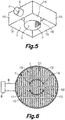
- Figures 1 to 4 show a dual plenum according to a first embodiment comprising a first chamber 1 and a second chamber 2 sharing a common wall 14 which has the shape of a vertical quadrangular prismatic wall.
- the common wall 14 is surrounded by a quadrangular prismatic side outer wall 15.
- the first chamber 1 is delimited by the common wall 14, the side outer wall 15, a first top wall 16, and a first bottom wall
- the second chamber 2 is delimited by the common wall 14, a second top wall 17, and a second bottom wall, so that the second chamber 2 is surrounded by the first chamber 1.
- An air inlet 3 is located in the side outer wall 15. Alternatively, the air inlet 3 could be located in the first top wall 16.
- a pressurized air supply conduit 9 is connected to an air supply source 8 and to the air inlet 3, so that pressurized air from the air supply source 8 is introduced to the first chamber 1.
- An air passage regulating device 7 is located in the common wall 14.
- the air passage regulating device 7 comprises a communication opening configured to selectively communicate the second chamber 2 to the first chamber 1 in response to an air pressure level in the first chamber 1 caused by a pressurized air flow rate supplied from the air supply source 8.
- the communication opening of the air passage regulating device 7 is formed in a region of the common wall 14 facing a portion of the side outer wall 15 opposite the air inlet 3 in this embodiment
- the air supply source 8, the pressurized air supply conduit 9, the air inlet 3, and the air passage regulating device 7 constitute an air-feed device configured to selectively introduce pressurized air to the first chamber 1 or to both the first chamber and the second chamber 2 in response to a supplied pressurized air flow rate.
- a first air outlet 10 provided with first diffusers 12 is located in the first bottom wall of the first chamber 1, and a second air outlet 11 provided with second diffusers 13 is located in the second bottom wall of the second chamber 2. Pressurized air is evacuated from the first and second chambers 1, 2 to an enclosure through the respective first and second air outlets 10, 11.
- the first and second diffusers 12, 13 are configured to direct air in one and the same downwards direction or in different directions, given the adjustable condition of the diffusers, for example of the grid type, according to the needs of the room or enclosure whose thermal load is to be controlled
- the first air outlet 10 and the corresponding first diffusers 12 provide a first air passage area S1 in a horizontal plane
- the second air outlet 11 and the corresponding second diffusers 13 provide a second air passage area S2 in a horizontal plane.
- the communication opening constituting the air passage regulating device 7 between the first and second chambers 1, 2 provides a third air passage area S3.
- the ratio of the third air passage area S3 to the first air passage area S1 is selected to allow a given flow rate of pressurized air to be shunt from the first chamber 1 to the second chamber 2 in response to the air pressure level in the first chamber 1. The higher is the air pressure level in the first chamber 1 the greater is the flow rate of pressurized air that is shunt from the first chamber 1 to the second chamber 2.
- the air flow rate entering the second chamber 2 through the third air passage area S3 increases and decreases with the rise and fall of the pressure in the first chamber 1, and the first and second air passage areas S1, S2 of the first and second air outlets 10, 11 of the first and second chambers 1, 2 add together as convenient at any time to keep the air output speed at a relatively constant level.
- the first top wall 16 has a perimetral edge connected to the side outer wall 15 and an inner edge connected to the common wall 14 and the second top wall 17 has a perimetral edge connected to the common wall 14.
- the first and second top walls 16, 17 are flush in a horizontal plane and can optionally be made of a single element, and the first and second diffusers 12, 13 are flush in another horizontal plane and can optionally be made of a single element.
- the first and second top walls 16, 17 could be staggered on different levels and the first and second diffusers 12, 13 could also be staggered on different horizontal levels.
- the first and second diffusers 12, 13 have a different design.
- the first and second diffusers 12, 13 could be of the same type o be a single diffuser, but in where the wall 14 they share determines that they can operate as two distinct, separate diffusers.
- Figure 5 shows a dual plenum according to a second embodiment which differs from the first embodiment ( Figures 1 to 4 ) in that the common wall 14 is a cylindrical wall instead of a quadrangular prismatic wall, and the air passage regulating device 7 comprises a plurality of smaller communication openings instead of a single greater communication opening.
- the smaller communication openings provide all together the third air passage area S3.
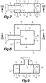
- Figure 6 shows a dual plenum according to a third embodiment which differs from the second embodiment ( Figure 5 ) in that the outer side wall 15 is a cylindrical wall instead of a quadrangular prismatic wall.
- the first and second diffusers 12, 13 are joined into a common diffuser spanning over the first and second outlets 10, 11.
- Figures 7 and 8 show a dual plenum according to a fourth embodiment which differs from the first embodiment ( Figures 1 to 4 ) in that the first chamber 1 is delimited by the common wall 14, the first top wall 16, and the first bottom wall in which the first air outlet 10 and the first diffusers 12 are located, and the second chamber 2 is delimited by the common wall 14, the side outer wall 15, the second top wall 17, and the second bottom wall in which the second air outlet 11 and the second diffusers 13 are located, so that the first chamber 1 is surrounded by the second chamber 2. Furthermore, the air inlet 3 is located in the common wall 14 and the pressurized air supply conduit 9 communicates with the air inlet 3 of the first chamber 1 going through the second chamber 2.
- the communication opening of the air passage regulating device 7 is formed in a region of the common wall 14, preferably opposite the air inlet 3.
- Figure 9 shows a dual plenum according to a fifth embodiment which differs from the fourth embodiment ( Figures 7 and 8 ) in that the air inlet 3 is located in the first top wall 16 instead of in the common wall 14, and the pressurized air supply conduit 9 is directly connected to the air inlet 3.
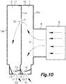
- Figure 10 shows a dual plenum according to a sixth embodiment having a vertical design in which the common wall 14 is a vertical partition wall which is connected inside of a vertical cylindrical or prismatic side outer wall 15a, 15b, so that the first and second chambers 1, 2 are arranged side by side adjacent to each other.
- the first chamber 1 is delimited by the common wall 14, a first portion of the side outer wall 15a, a first top wall 16, and a first bottom wall in which the first air outlet 10 and the first diffusers 12 are located.
- the second chamber 2 is delimited by the common wall 14, a second portion of the side outer wall 15b, a second top wall 17 and a second bottom wall in which the second air outlet 11 and the second diffusers 13 are located.
- Surfaces 16 and 17 are in general coplanar or can optionally be made of a single surface.
- the air inlet 3 is located in the first portion of the side outer wall 15a and the pressurized air supply conduit 9 is connected to the air supply source 8 and to the air inlet 3.
- the air inlet 3 could be located in the first top wall 16 and the pressurized air supply conduit 9 directly connected to the air inlet 3.
- the communication opening of the air passage regulating device 7 is located in the common wall 14.
- the first and second diffusers 12, 13 provide respective first and second air passage areas S1, S2 and are configured to direct air in one and the same inclined downwards direction or in different directions taking into account there are two different diffusers 12 and 13. Air circulation is shown by arrows in Figure 10 .
- Figure 11 shows a dual plenum according to a seventh embodiment which differs from the sixth embodiment ( Figure 10 ) in that the air inlet 3 is located in the common wall 14 and the pressurized air supply conduit 9 communicates with the air inlet 3 of the first chamber 1 going through the second chamber 2. Alternatively, the air inlet 3 could be located in the first top wall 16. Air circulation is shown by arrows in Figure 11 .
- Figures 12 and 13 show a dual plenum according to an eighth embodiment which differs from the first embodiment ( Figures 1 to 4 ) in that the air passage regulating device 7 comprises a one-way valve device 4 associated to the communication opening.
- the communication opening is located in a vertical flat section of the common wall 14.
- the one-way valve device 4 comprises a flexible sheet secured at an upper edge thereof to the common wall 14 over the communication opening.
- the flexible sheet is configured to freely hang by gravity thereby blocking the communication opening when a pressure below a specific threshold exists in the first chamber 1 ( Figure 12 ), and to bend to open the communication opening to a greater or lesser degree in response to a pressure above the specific threshold value exerted on the flexible sheet from the first chamber 1 ( Figure 13 ) thereby allowing a given flow rate of pressurized air to be shunt from the first chamber 1 to the second chamber 2.
- Air circulation is shown by arrows in Figures 12 and 13 .
- the flexible sheet may be secured by attachment 18 at one side of the communication opening.
- Figure 14 shows a dual plenum according to a ninth embodiment which differs from the fourth embodiment ( Figure 7 ) in that the communication opening is located in any vertical section of the common wall 14 and in that the one-way valve device 4 comprises a sheet connected by a hinge 19 at an upper edge thereof to the common wall 14 over the communication opening.
- the rigid sheet is biased to freely hang into a closed position (shown in solid lines in Figure 14 ) blocking the communication opening by the action of its own weight.
- the sheet has the capacity to pivot about the hinge 19 to open the communication opening to a greater or lesser degree (shown in dashed lines in Figure 14 ) in response to a pressure above a specific threshold value exerted on the sheet from the first chamber 1 thereby allowing a given flow rate of pressurized air to be shunt from the first chamber 1 to the second chamber 2.
- Figures 15 and 16 show a dual plenum according to a tenth embodiment which differs from the eighth embodiment ( Figures 12 and 13 ) in the first instance in that the first top wall 16 has a perimetral edge connected to the side outer wall 15, the second top wall 17 has a perimetral edge connected to the common wall 14, and a section of the first chamber 1 extends between the first top wall 16 and the second top wall 17 thereby the second top wall 17 is also a wall common to the first and second chambers 1, 2 in addition to the common wall 14.
- this tenth embodiment differs from the eighth embodiment in that the communication opening is located in the second top wall 17 common to the first and second chambers 1, 2, and the one-way valve device 4 comprises a sheet connected by a hinge 19 at an edge thereof to the common wall 14 adjacent to the communication opening.
- the sheet is biased to a closed position ( Figure 15 ) blocking the communication opening by the action of an elastic element 20.
- the sheet has the capacity to pivot about the hinge 19 to open the communication opening to a greater or lesser degree ( Figure 16 ) in response to a pressure above a specific threshold value exerted on the sheet from the first chamber 1 thereby allowing a given flow rate of pressurized air to be shunt from the first chamber 1 to the second chamber 2.
- Air circulation is shown by arrows in Figures 15 and 16 .
- the one-way valve device 4 could be located in in any other wall common to the first and second chambers 1, 2.
- Figure 17 shows a dual plenum according to an eleventh embodiment which differs from the ninth embodiment ( Figure 14 ) in the first instance in that the first top wall 16 has a perimetral edge connected to the common wall 14, the second top wall 17 has a perimetral edge connected to the side outer wall 15, and a section of the second chamber 2 extends between the first top wall 16 and the second top wall 17 thereby the first top wall 16 is also a wall common to the first and second chambers 1, 2 in addition to the common wall 14.
- this eleventh embodiment differs from the ninth embodiment in that the one-way valve device 4 is an automatically actuated mechanical valve device 21 having a movable part which partially opens, closes, or obstructs one or more orifices or conduits associated to the communication opening thereby allowing a given flow rate of pressurized air to be shunt from the first chamber 1 to the second chamber 2.
- One or more pressure sensors 22 are arranged in the first chamber 1 to sense pressure therein, and an electronic control device 23 operates the mechanical valve device 21 in response to a signal representative of a a pressure above a specific threshold value in the first chamber 1 received from the one or more pressure sensors 22.
- the communication opening and the associated mechanical valve device 21 are located in the first top wall 16, although alternatively they could be located in any other wall common to the first and second chambers 1, 2.
- more than one air passage regulating device 7, each having one or more communication openings could be placed in one or more of the walls common to the first and second chambers 1, 2.
- more than one one-way valve device 4, each associated to a communication opening could be placed in one or more of the walls common to the first and second chambers 1, 2.
Landscapes
- Engineering & Computer Science (AREA)
- Chemical & Material Sciences (AREA)
- Combustion & Propulsion (AREA)
- Mechanical Engineering (AREA)
- General Engineering & Computer Science (AREA)
- Physics & Mathematics (AREA)
- Fluid Mechanics (AREA)
- Duct Arrangements (AREA)
Applications Claiming Priority (2)
| Application Number | Priority Date | Filing Date | Title |
|---|---|---|---|
| EP19382679 | 2019-08-05 | ||
| ES201932087U ES1244990Y (es) | 2019-12-18 | 2019-12-18 | Plenum multiple para distribucion de aire |
Publications (1)
| Publication Number | Publication Date |
|---|---|
| EP3772624A1 true EP3772624A1 (de) | 2021-02-10 |
Family
ID=71995910
Family Applications (1)
| Application Number | Title | Priority Date | Filing Date |
|---|---|---|---|
| EP20382635.9A Withdrawn EP3772624A1 (de) | 2019-08-05 | 2020-07-15 | Doppelplenum zur luftverteilung |
Country Status (3)
| Country | Link |
|---|---|
| US (1) | US20210041131A1 (de) |
| EP (1) | EP3772624A1 (de) |
| CA (1) | CA3088960A1 (de) |
Families Citing this family (3)
| Publication number | Priority date | Publication date | Assignee | Title |
|---|---|---|---|---|
| US11632874B1 (en) * | 2020-07-22 | 2023-04-18 | ZT Group Int'l, Inc. | Regulating airflow in a computer system |
| US12480682B2 (en) * | 2021-10-08 | 2025-11-25 | Air Distribution Technologies Ip, Llc | Displacement diffuser |
| JP2024007279A (ja) * | 2022-07-05 | 2024-01-18 | オイレスEco株式会社 | 換気装置および換気方法 |
Citations (8)
| Publication number | Priority date | Publication date | Assignee | Title |
|---|---|---|---|---|
| US3699871A (en) * | 1970-02-26 | 1972-10-24 | Svenska Flaektfabriken Ab | Supply air device for injection of preferably cold ventilation air |
| US3929280A (en) | 1973-07-11 | 1975-12-30 | Cape Air Cond Pty | Terminal air outlet device |
| US4203485A (en) * | 1976-12-17 | 1980-05-20 | Aronoff Melvin S | Multizone air terminal |
| US4259898A (en) | 1978-10-02 | 1981-04-07 | Gebruder Trox, Gesellschaft Mit Beschrankter Haftung | Ceiling air outlet for climate control system |
| US6986708B2 (en) | 2002-05-17 | 2006-01-17 | Airfixture L.L.C. | Method and apparatus for delivering conditioned air using dual plenums |
| DE202012103044U1 (de) * | 2012-08-13 | 2013-11-14 | Meltem Wärmerückgewinnung GmbH & Co. KG | Unterdruckklappe |
| FR3000540A1 (fr) * | 2012-12-27 | 2014-07-04 | Hidria Imp Klima D O O | Prechambre variable |
| ES1244990U (es) * | 2019-12-18 | 2020-04-22 | Madel Air Technical Diffusion Sa | Plenum multiple para distribucion de aire |
-
2020
- 2020-07-15 EP EP20382635.9A patent/EP3772624A1/de not_active Withdrawn
- 2020-08-04 CA CA3088960A patent/CA3088960A1/en active Pending
- 2020-08-05 US US16/985,279 patent/US20210041131A1/en not_active Abandoned
Patent Citations (8)
| Publication number | Priority date | Publication date | Assignee | Title |
|---|---|---|---|---|
| US3699871A (en) * | 1970-02-26 | 1972-10-24 | Svenska Flaektfabriken Ab | Supply air device for injection of preferably cold ventilation air |
| US3929280A (en) | 1973-07-11 | 1975-12-30 | Cape Air Cond Pty | Terminal air outlet device |
| US4203485A (en) * | 1976-12-17 | 1980-05-20 | Aronoff Melvin S | Multizone air terminal |
| US4259898A (en) | 1978-10-02 | 1981-04-07 | Gebruder Trox, Gesellschaft Mit Beschrankter Haftung | Ceiling air outlet for climate control system |
| US6986708B2 (en) | 2002-05-17 | 2006-01-17 | Airfixture L.L.C. | Method and apparatus for delivering conditioned air using dual plenums |
| DE202012103044U1 (de) * | 2012-08-13 | 2013-11-14 | Meltem Wärmerückgewinnung GmbH & Co. KG | Unterdruckklappe |
| FR3000540A1 (fr) * | 2012-12-27 | 2014-07-04 | Hidria Imp Klima D O O | Prechambre variable |
| ES1244990U (es) * | 2019-12-18 | 2020-04-22 | Madel Air Technical Diffusion Sa | Plenum multiple para distribucion de aire |
Also Published As
| Publication number | Publication date |
|---|---|
| CA3088960A1 (en) | 2021-02-05 |
| US20210041131A1 (en) | 2021-02-11 |
Similar Documents
| Publication | Publication Date | Title |
|---|---|---|
| EP3772624A1 (de) | Doppelplenum zur luftverteilung | |
| EP3475626B1 (de) | Umgebungskontroll- und luftverteilungssystem und verfahren zur verwendung davon | |
| US6099406A (en) | Modular integrated terminals and associated systems for heating and cooling | |
| US20110290454A1 (en) | Air Cooling And Air Dehumidifying Module Comprising Capillary Tube Mats And Method of Using It | |
| WO2007080162A2 (en) | Cooling and ventilation device | |
| US20130023198A1 (en) | System and method for delivering air | |
| US20240381588A1 (en) | Modular air cooling and distribution systems and methods | |
| US4489881A (en) | Air delivery system for hospital rooms and the like | |
| EP2557365B1 (de) | Fluidverteilungssteuersystem | |
| US3867980A (en) | Air conditioning system | |
| JP7217596B2 (ja) | 空調システム | |
| US3779275A (en) | Environmental air distribution control system powered by system pressure | |
| KR840000064B1 (ko) | 공기 조화장치 | |
| EP1134509B1 (de) | Verfahren und Anordnung zur Steuerung eines Belüftungssystems | |
| EP4327030B1 (de) | Raumklimaanlage | |
| US5672103A (en) | Method and device for feeding the various rooms of premises with ventilation air | |
| US3744556A (en) | Air distribution system | |
| US4323112A (en) | No energy band temperature control | |
| KR100851589B1 (ko) | 공기 조화 시스템 | |
| CN119860573B (zh) | 新风处理系统 | |
| ES1244990U (es) | Plenum multiple para distribucion de aire | |
| GB2235551A (en) | Air conditioning | |
| RU2059935C1 (ru) | Вентиляционный клапан-распределитель | |
| JP2024040901A (ja) | ダクトレス室圧制御システム | |
| FI110140B (fi) | Käyttövesipatterin venttiilisovitelma ja käyttövesipatteri |
Legal Events
| Date | Code | Title | Description |
|---|---|---|---|
| PUAI | Public reference made under article 153(3) epc to a published international application that has entered the european phase |
Free format text: ORIGINAL CODE: 0009012 |
|
| STAA | Information on the status of an ep patent application or granted ep patent |
Free format text: STATUS: THE APPLICATION HAS BEEN PUBLISHED |
|
| AK | Designated contracting states |
Kind code of ref document: A1 Designated state(s): AL AT BE BG CH CY CZ DE DK EE ES FI FR GB GR HR HU IE IS IT LI LT LU LV MC MK MT NL NO PL PT RO RS SE SI SK SM TR |
|
| AX | Request for extension of the european patent |
Extension state: BA ME |
|
| STAA | Information on the status of an ep patent application or granted ep patent |
Free format text: STATUS: REQUEST FOR EXAMINATION WAS MADE |
|
| 17P | Request for examination filed |
Effective date: 20210715 |
|
| RBV | Designated contracting states (corrected) |
Designated state(s): AL AT BE BG CH CY CZ DE DK EE ES FI FR GB GR HR HU IE IS IT LI LT LU LV MC MK MT NL NO PL PT RO RS SE SI SK SM TR |
|
| GRAJ | Information related to disapproval of communication of intention to grant by the applicant or resumption of examination proceedings by the epo deleted |
Free format text: ORIGINAL CODE: EPIDOSDIGR1 |
|
| GRAP | Despatch of communication of intention to grant a patent |
Free format text: ORIGINAL CODE: EPIDOSNIGR1 |
|
| GRAP | Despatch of communication of intention to grant a patent |
Free format text: ORIGINAL CODE: EPIDOSNIGR1 |
|
| STAA | Information on the status of an ep patent application or granted ep patent |
Free format text: STATUS: GRANT OF PATENT IS INTENDED |
|
| INTG | Intention to grant announced |
Effective date: 20230627 |
|
| STAA | Information on the status of an ep patent application or granted ep patent |
Free format text: STATUS: THE APPLICATION IS DEEMED TO BE WITHDRAWN |
|
| 18D | Application deemed to be withdrawn |
Effective date: 20231108 |