EP3772616A1 - Ensemble de turbine à gaz comprenant une chambre de combustion séquentielle et procédé de fonctionnement de cet ensemble de turbine à gaz - Google Patents
Ensemble de turbine à gaz comprenant une chambre de combustion séquentielle et procédé de fonctionnement de cet ensemble de turbine à gaz Download PDFInfo
- Publication number
- EP3772616A1 EP3772616A1 EP19190695.7A EP19190695A EP3772616A1 EP 3772616 A1 EP3772616 A1 EP 3772616A1 EP 19190695 A EP19190695 A EP 19190695A EP 3772616 A1 EP3772616 A1 EP 3772616A1
- Authority
- EP
- European Patent Office
- Prior art keywords
- combustor
- gas turbine
- air
- fuel
- injecting
- Prior art date
- Legal status (The legal status is an assumption and is not a legal conclusion. Google has not performed a legal analysis and makes no representation as to the accuracy of the status listed.)
- Granted
Links
Images


Classifications
-
- F—MECHANICAL ENGINEERING; LIGHTING; HEATING; WEAPONS; BLASTING
- F23—COMBUSTION APPARATUS; COMBUSTION PROCESSES
- F23R—GENERATING COMBUSTION PRODUCTS OF HIGH PRESSURE OR HIGH VELOCITY, e.g. GAS-TURBINE COMBUSTION CHAMBERS
- F23R3/00—Continuous combustion chambers using liquid or gaseous fuel
- F23R3/02—Continuous combustion chambers using liquid or gaseous fuel characterised by the air-flow or gas-flow configuration
- F23R3/26—Controlling the air flow
-
- F—MECHANICAL ENGINEERING; LIGHTING; HEATING; WEAPONS; BLASTING
- F23—COMBUSTION APPARATUS; COMBUSTION PROCESSES
- F23R—GENERATING COMBUSTION PRODUCTS OF HIGH PRESSURE OR HIGH VELOCITY, e.g. GAS-TURBINE COMBUSTION CHAMBERS
- F23R3/00—Continuous combustion chambers using liquid or gaseous fuel
- F23R3/02—Continuous combustion chambers using liquid or gaseous fuel characterised by the air-flow or gas-flow configuration
- F23R3/16—Continuous combustion chambers using liquid or gaseous fuel characterised by the air-flow or gas-flow configuration with devices inside the flame tube or the combustion chamber to influence the air or gas flow
- F23R3/18—Flame stabilising means, e.g. flame holders for after-burners of jet-propulsion plants
- F23R3/20—Flame stabilising means, e.g. flame holders for after-burners of jet-propulsion plants incorporating fuel injection means
-
- F—MECHANICAL ENGINEERING; LIGHTING; HEATING; WEAPONS; BLASTING
- F02—COMBUSTION ENGINES; HOT-GAS OR COMBUSTION-PRODUCT ENGINE PLANTS
- F02C—GAS-TURBINE PLANTS; AIR INTAKES FOR JET-PROPULSION PLANTS; CONTROLLING FUEL SUPPLY IN AIR-BREATHING JET-PROPULSION PLANTS
- F02C3/00—Gas-turbine plants characterised by the use of combustion products as the working fluid
- F02C3/14—Gas-turbine plants characterised by the use of combustion products as the working fluid characterised by the arrangement of the combustion chamber in the plant
-
- F—MECHANICAL ENGINEERING; LIGHTING; HEATING; WEAPONS; BLASTING
- F02—COMBUSTION ENGINES; HOT-GAS OR COMBUSTION-PRODUCT ENGINE PLANTS
- F02C—GAS-TURBINE PLANTS; AIR INTAKES FOR JET-PROPULSION PLANTS; CONTROLLING FUEL SUPPLY IN AIR-BREATHING JET-PROPULSION PLANTS
- F02C9/00—Controlling gas-turbine plants; Controlling fuel supply in air- breathing jet-propulsion plants
- F02C9/16—Control of working fluid flow
- F02C9/18—Control of working fluid flow by bleeding, bypassing or acting on variable working fluid interconnections between turbines or compressors or their stages
-
- F—MECHANICAL ENGINEERING; LIGHTING; HEATING; WEAPONS; BLASTING
- F23—COMBUSTION APPARATUS; COMBUSTION PROCESSES
- F23R—GENERATING COMBUSTION PRODUCTS OF HIGH PRESSURE OR HIGH VELOCITY, e.g. GAS-TURBINE COMBUSTION CHAMBERS
- F23R3/00—Continuous combustion chambers using liquid or gaseous fuel
- F23R3/28—Continuous combustion chambers using liquid or gaseous fuel characterised by the fuel supply
- F23R3/286—Continuous combustion chambers using liquid or gaseous fuel characterised by the fuel supply having fuel-air premixing devices
-
- F—MECHANICAL ENGINEERING; LIGHTING; HEATING; WEAPONS; BLASTING
- F23—COMBUSTION APPARATUS; COMBUSTION PROCESSES
- F23R—GENERATING COMBUSTION PRODUCTS OF HIGH PRESSURE OR HIGH VELOCITY, e.g. GAS-TURBINE COMBUSTION CHAMBERS
- F23R3/00—Continuous combustion chambers using liquid or gaseous fuel
- F23R3/28—Continuous combustion chambers using liquid or gaseous fuel characterised by the fuel supply
- F23R3/34—Feeding into different combustion zones
- F23R3/346—Feeding into different combustion zones for staged combustion
-
- F—MECHANICAL ENGINEERING; LIGHTING; HEATING; WEAPONS; BLASTING
- F23—COMBUSTION APPARATUS; COMBUSTION PROCESSES
- F23R—GENERATING COMBUSTION PRODUCTS OF HIGH PRESSURE OR HIGH VELOCITY, e.g. GAS-TURBINE COMBUSTION CHAMBERS
- F23R3/00—Continuous combustion chambers using liquid or gaseous fuel
- F23R3/28—Continuous combustion chambers using liquid or gaseous fuel characterised by the fuel supply
- F23R3/36—Supply of different fuels
-
- F—MECHANICAL ENGINEERING; LIGHTING; HEATING; WEAPONS; BLASTING
- F23—COMBUSTION APPARATUS; COMBUSTION PROCESSES
- F23R—GENERATING COMBUSTION PRODUCTS OF HIGH PRESSURE OR HIGH VELOCITY, e.g. GAS-TURBINE COMBUSTION CHAMBERS
- F23R2900/00—Special features of, or arrangements for continuous combustion chambers; Combustion processes therefor
- F23R2900/03341—Sequential combustion chambers or burners
Definitions
- the present invention relates to the technical field of the gas turbine assemblies for power plants (in the following only "gas turbine”).
- the present invention relates to a gas turbine having a sequential combustor and to a method for operating this gas turbine.
- sequential combustor we mean a combustor assembly comprising an upstream or first combustor followed by a downstream or second combustor.
- the second combustor may also be realized in form of fuel injectors arranged close to the exit of the combustor.
- the first combustor is configured for receiving compressed air and mixing this air with fuel whereas the second combustor is configured for receiving the hot gas leaving the first combustor and adding fuel and air into this hot gas.
- the first combustor is provided with a spark igniter whereas the second combustor is configured for performing a self/spontaneous ignition.
- the gas turbine of the present invention and the related method for operating refers to the above sequential combustor when it is fed by a highly reactive fuel, for instance fuel comprising H2.
- a gas turbine assembly for power plants comprises a rotor provided with a compressor unit, a combustor unit and at least a turbine unit.
- the compressor is configured for compressing air supplied at a compressor inlet.
- the compressed air leaving the compressor flows into a plenum and from there into a combustor.
- the combustor comprises a plurality of burners configured for injecting fuel in the compressed air.
- the mixture of fuel and compressed air flows into a combustion chamber where this mixture is combusted.
- the resulting hot gas leaves the combustion chamber and is expanded in the turbine performing work on the rotor.
- the turbine comprises a plurality of stages, or rows, of rotor blades that are interposed by a plurality of stages, or rows, of stator vanes.
- the rotor blades are connected to the rotor whereas the stator vanes are connected to a vane carrier that is a concentric casing surrounding the turbine unit.
- a high turbine inlet temperature is required.
- this high temperature involves an undesired high NOx emission level.
- the so called “sequential" gas turbine is particularly suitable.
- a sequential gas turbine comprises two combustors or combustion stages in series wherein each combustor is provided with a plurality of burners and with at least a combustion chamber. Following the main gas flow direction, usually the upstream or first combustor comprises a plurality of so-called "first" burners.
- first burners may be “premix burners” wherein the term “premix” emphasizes the fact that each burner of the first combustor is configured not only for injecting the fuel directly in the compressed air (for instance with a so called diffusion flame) but also for mixing (with a swirl) the compressed air and the fuel before injecting the mixture into the combustion chamber. Therefore in the following with the terms “first burner” we mean the burner in the first stage of the sequential combustor wherein each burner may be configured for receiving the compressed air and injecting fuel in this coming air for realizing a diffusion flame (e.g. by pilot lance without any premix) and/or a premix flame.
- a diffusion flame e.g. by pilot lance without any premix
- the downstream or second combustor is also called “reheat” or “sequential" combustor and it is fed by the hot gas leaving the first combustor.
- the second combustor is provided with a plurality of burners configured for injecting fuel in the hot gas coming from the first combustor. Due to the high gas temperature, the operating conditions downstream the second burners allow a self/spontaneous ignition of the fuel/air mixture.
- these reheat burners are configured for performing a premix for the hot gas and the fuel before the spontaneous ignition. Therefore in the following with terms second burners we mean the burners at the second stage of combustion in the sequential combustor.
- the first and second combustors are annular shaped and are physically separated by a stage of turbine blades, called high pressure turbine.
- the gas turbine is not provided with the high pressure turbine and the combustor unit is realized in form of a plurality of can-combustors.
- each can-combustor comprises a first combustor (first stage) and a second (second stage) combustor arranged directly one downstream the other inside the common can shaped casing.
- the burners are configured for injecting different kinds of fuel, i.e. liquid and gas fuel, and carrying air (i.e. a little part of the compressed air leaving the compressor).
- the burners are provided with separated channels or ducts for feeding the gas fuel, liquid fuel and carrying air to relevant burner nozzles.
- EP 2206963 discloses a prior art gas turbine provided with sequential can combustors. According to this example, the second burners are arranged close to the exit of the combustor and are fed by fuel and a spilled part of the compressed air directed to the first combustor.
- a change in fuel reactivity implies a change in flame location.
- higher fuel reactivity like H2 forces the flame to move upstream, increasing NOx emissions, and potentially overheating the burners. Consequently, when burning highly reactive fuels (e.g. fuels containing large quantities of either higher hydrocarbons or hydrogen) the flame moves upstream compared to the case of natural gas, thus increasing the risk of flashback. Since the position of the flame in the second combustor can be effectively controlled by the temperature at the inlet of the reheat combustor (self/spontaneous ignition), by lowering the inlet temperature it is therefore possible to move the flame downstream.
- the negative effect of higher fuel reactivity (flashback) in the reheat combustor can be compensated by lowering the first stage temperature.
- flashback in order to mitigate the flashback risks by keeping the flame at its design position in the reheat combustor is obtained by simply injecting less fuel in the first stage of combustion.
- this prior art practice generates high NOx emissions and therefore a large amounts of diluents (nitrogen, steam) need to be added in the gas flow and/or selective catalytic reduction devices have to be used to keep the NOx emissions below the limits.
- this known solution cannot be applied for very reactive fuel having high rate of H2. Indeed, the first stage flame temperature cannot be lowered beyond a certain limit called "lean blow out" temperature. Under this temperature the operation of the first combustor is compromised.
- a primary scope of the present invention is to provide a gas turbine assembly for power plants (in the following only gas turbine) and a method for operating this gas turbine suitable for overcoming the drawbacks of the current prior art practice.
- the scope of the present invention is to provide a gas turbine having a sequential combustor configured to allow a reliable control of the temperature inside the combustor also when the supplied fuel is a highly reactive fuel, for instance H2-based fuel having an high % of H2 (in vol. up to 100%).
- a gas turbine suitable for implementing the present invention is a so called sequential gas turbine, i.e. a gas turbine having an axis and comprising:
- a sequential combustor comprises:
- the gas turbine according the claimed solution comprises a feeding or a source of a high reactive fuel (for instance a H2 based fuel).
- the supplied compressed air is the air leaving a compressor upstream arranged in the gas turbine with respect to the sequential combustor.
- the present description does not provide any limitation referring to the shape of the sequential combustor. In any case, in the following description of the drawings two different embodiments of the claimed gas turbine will be described.
- the gas turbine moreover comprises an innovative by-pass circuit configured for spilling at least part of the compressed air directed from the compressor to the first burners and for injecting this spilled air inside the sequential combustor downstream the first burners (i.e. by-passing the first burners) directly inside the combustor casing (i.e. not passing by the second burners).
- circuit we mean a real duct or path limited by an additional structure but also some simple injection points or holes that can be provided in the combustor casing/structure facing the plenum fed by the compressed air directed to the first burner.
- the first stage fuel massflow can be adapted depending on the fuel reactivity.
- the first combustor and the second combustor are annular shaped and divided by a stage of high pressure turbine.
- This stage of high pressure turbine comprises at least an upstream high pressure vane and at least a downstream high pressure turbine blade.
- the first burners comprise a front panel supporting the burners and facing the first combustion chamber.
- the combustion chamber is limited by an inner wall and an outer wall (inner and outer are referred to the gas turbine axis).
- the second combustor Downstream the high pressure turbine blade the second combustor comprises a burner chamber, i.e. a chamber receiving the hot gas leaving the first combustor, provided with a fuel lance or other injecting fuel device, and a second combustion chamber.
- the air by-pass circuit of the present invention may be implemented according to some different embodiments.
- the by-pass circuit may be configured:
- the by-pass circuit may be configured for injecting the spilled air inside the second combustor; in particular:
- a different kind of a gas turbine that can be provided with the innovative by-pass circuit of the present invention may comprises a sequential combustor assembly in form of a plurality of can combustors.
- each can combustor comprises a first and a second combustor wherein the first combustor comprises a front panel supporting the burners and a liner defining the first combustion chamber.
- this liner may be provided with a plurality of holes, namely dilution air injection holes.
- each can combustor may be provided with an air mixer between the first combustion chamber and the second burner.
- the by-pass circuit may be configured for injecting the spilled air inside the first combustion chamber through:
- the liner may also be provided with other holes having a specific layout configured for generating a thermacoustic effect inside the combustion chamber.
- the liner dilution air injection holes may be realized upstream or downstream these thermacoustic holes.
- the by-pass circuit may be directly connected to the thermacoustic holes providing these holes with a two different features.
- the by-pass circuit may be configured for injecting the spilled air as additional air through the air mixer and/or for injecting the spilled air between the air mixer and the second burner.
- the present invention may also be defined as a method for operating a gas turbine for power plant, in particular a method for operating a gas turbine for power plant when fed by a high reactive fuel.
- This method comprises the steps of:
- An implicit step is feeding the gas turbine with a high reactive fuel, for instance a H2 based fuel.
- the method of the present invention may comprise the step of adapting the fuel split between the first and the second combustor in order to have an appropriate inlet temperature of the second combustor.
- FIG. 1 is a schematic view of a first example of a gas turbine 1 comprising a sequential combustor that can be provided with the innovative features according to the present invention.
- figure 1 discloses a gas turbine with a high pressure and a low pressure turbine.
- the gas turbine 1 of figure 1 comprises a compressor 3, a first combustor 31, a high-pressure turbine 5, a second combustor 32 and a low-pressure turbine 7.
- the compressor 3 and the two turbines 5, 7 are part of or are connected to a common rotor 8 rotating around an axis 9 and surrounded by a concentric casing 10.
- the compressor 3 is supplied with air and is provided with rotating blades 18 and stator vanes 19 configured for compressing the air entering the compressor 3.
- the compressed air flows into a plenum 11 and from there into a plurality of first burners 12 of the first combustor 31 arranged as a ring around the axis 9.
- Each first burner 12 in configured for injecting at least a kind of fuel (supplied by at least a first fuel supply 13) in the air flow.
- this first burner 12 may be defined as a "premix" burner because is configured for mixing the air and the injected fuel before the ignition point.
- the fuel/compressed air mixture flows into a first combustion chamber 4 annularly shaped where this mixture are combusted via a forced ignition, for instance by a spark igniter.
- the resulting hot gas leaves the first combustor chamber 4 and is partially expanded in the high-pressure turbine 5 performing work on the rotor 8.
- Downstream of the high-pressure turbine 5 the hot gas partially expanded flows into a second burner 33 where at least a kind of fuel supplied by at least a fuel lance 14 is injected.
- the partially expanded gas has a high temperature and contains sufficient oxygen for a further combustion that occurred based on a self-ignition in the second combustion chamber 6 arranged downstream the second burner 33.
- This second burner 33 is also called "reheat" burner.
- the reheated hot gas leaves the second combustion chamber 6 and flows in the low-pressure turbine 7 where it is expanded performing work on the rotor 8.
- the low-pressure turbine 7 comprises a plurality of stages, or rows, of rotor blades 15 arranged in series in the main flow direction. Such stages of blades 15 are interposed by stages of stator vanes 16.
- the rotor blades 15 are connected to the rotor 8 whereas the stator vanes 16 are connected to a vane carrier 17 that is a concentric casing surrounding the low-pressure turbine 7.
- FIG. 2 is a schematic view of a second example of a gas turbine 20 comprising a sequential combustor that can be provided with the innovative features according to the present invention.
- figure 2 discloses a gas turbine 20 provided with a compressor 29, a turbine 21 and a sequential combustor 22.
- the sequential combustor 22 of figure 2 comprises a plurality of so-called can combustors, i.e. a plurality of casings wherein each can combustor houses a plurality of first burners 24, for instance four first burners 24, a first combustion chamber 25, a second burner 26, and a second combustion chamber 27.
- an air mixer (represented with reference 47 only in figure 3 ) may be provided for adding air in the hot gas leaving the first combustion chamber 25.
- the sequential combustor arrangement is at least in part housed in an outer casing 28 supporting the plurality of can combustor 22 arranged as a ring around the turbine axis.
- At least a kind of fuel is introduced via a first fuel injector (not shown) into the first burners 24 wherein the fuel is mixed with the compressed gas supplied by the compressor 29.
- each first burner 24 of this embodiment is a "premix" burner configured for generating a premixed flame.
- the hot gas leaving the second combustion chamber 27 expands in the turbine 21 performing work on a rotor 30.
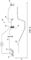
- FIG. 3 is a schematic view of a can combustor 22 that may be a combustor of the turbine of figure 2 .
- figure 3 discloses also a diagram showing how the temperature changes along this can combustor.
- the first stage premixed burner 24 utilizes aerodynamic structures to stabilize a propagating premix flame providing excellent flame stability and combustion efficiency over an extensive operational range. This flame having a correct distance from the burner nozzles is represented by the reference 34.
- the second burner 26 is a primarily auto-ignition controlled burner. The flame generated by the second burner 26 having a correct distance is represented by the reference 35.
- the proposed solution for moving downstream the flames 35' to a correct position 35 is to reduce the first stage flame temperature (lowering the line 36 of the diagram of Figure 3 ) by reducing the fuel injected in the first stage.
- this solution may not be sufficient on its own when the fuel is a very high reactive fuel, i.e. having a very high hydrogen content up to 100%. Indeed, in this case in order to report the flame 35' in the correct position a theoretical too low first stage flame temperature is required, i.e. a first stage flame temperature under the so called lean blow out temperature. Therefore, according to the prior art practice this compensation is possible only for fuel having a limited % of H2 in Vol.
- the present invention provides the solution of adding at least air by-pass circuit configured for injecting part of the compressed air in the combustor by-passing the first burners.
- the inlet temperature (or the second flame position) may be controlled without lowering the first stage flame temperature under the so called lean blow out temperature.
- the reference 69 refers to a feeding of a highly reactive fuel connected to the first burners and to the second burners
- figure 4 is the enlarged view of the portion of figure 1 labelled with the reference IV.
- figure 4 disclose the sequential combustor assembly of figure 2 .
- the air by-pass circuit of the present invention may be implemented according to some different embodiments.
- the by-pass circuit may be configured:
- the by-pass circuit may be configured for injecting the spilled air inside the second combustor 32 through:
- figure 5 is a more detailed view of the combustor assembly of figure 2 .
- the combustor 22 comprises the first burners 24, the relative front panel 59, the liner 60 with holes 63 defining the first combustion chamber 25 and an air mixer 47.
- a second burner 26 is present with the relative feeding of fuel 61 (in particular a source of H2 based fuel) followed by the second combustion chamber 27 and a transition piece 62.
- the air by-pass circuit of the present invention may be implemented according to some different embodiments.
- the by-pass circuit may be configured for injecting the spilled air inside the first combustion chamber 25 through:
Landscapes
- Engineering & Computer Science (AREA)
- Chemical & Material Sciences (AREA)
- Combustion & Propulsion (AREA)
- Mechanical Engineering (AREA)
- General Engineering & Computer Science (AREA)
- Physics & Mathematics (AREA)
- Fluid Mechanics (AREA)
Priority Applications (2)
| Application Number | Priority Date | Filing Date | Title |
|---|---|---|---|
| EP19190695.7A EP3772616B1 (fr) | 2019-08-08 | 2019-08-08 | Procédé de fonctionnement d'un ensemble de turbine à gaz comprenant une chambre de combustion séquentielle |
| CN202010789722.5A CN112344369B (zh) | 2019-08-08 | 2020-08-07 | 包括顺序燃烧器的燃气涡轮组件及其运行方法 |
Applications Claiming Priority (1)
| Application Number | Priority Date | Filing Date | Title |
|---|---|---|---|
| EP19190695.7A EP3772616B1 (fr) | 2019-08-08 | 2019-08-08 | Procédé de fonctionnement d'un ensemble de turbine à gaz comprenant une chambre de combustion séquentielle |
Publications (2)
| Publication Number | Publication Date |
|---|---|
| EP3772616A1 true EP3772616A1 (fr) | 2021-02-10 |
| EP3772616B1 EP3772616B1 (fr) | 2024-02-07 |
Family
ID=67587466
Family Applications (1)
| Application Number | Title | Priority Date | Filing Date |
|---|---|---|---|
| EP19190695.7A Active EP3772616B1 (fr) | 2019-08-08 | 2019-08-08 | Procédé de fonctionnement d'un ensemble de turbine à gaz comprenant une chambre de combustion séquentielle |
Country Status (2)
| Country | Link |
|---|---|
| EP (1) | EP3772616B1 (fr) |
| CN (1) | CN112344369B (fr) |
Families Citing this family (2)
| Publication number | Priority date | Publication date | Assignee | Title |
|---|---|---|---|---|
| EP4083509B1 (fr) * | 2021-04-30 | 2024-12-25 | Ansaldo Energia Switzerland AG | Procédé d'étalonnage d'un brûleur de turbine à gaz pendant la remise en état ou la production à l'aide d'une broche d'étalonnage |
| US12253050B2 (en) * | 2022-04-12 | 2025-03-18 | General Electric Company | Combined cycle propulsion system for hypersonic flight |
Citations (7)
| Publication number | Priority date | Publication date | Assignee | Title |
|---|---|---|---|---|
| EP2206963A2 (fr) | 2009-01-07 | 2010-07-14 | General Electric Company | Configurations de stratification de combustible à injection tardive pauvre |
| EP2287456A1 (fr) * | 2009-08-17 | 2011-02-23 | Alstom Technology Ltd | Turbine à gaz et procédé de fonctionnement d'une turbine à gaz |
| US20130219904A1 (en) * | 2009-04-01 | 2013-08-29 | Alstom Technology Ltd. | Methods of Operation of A Gas Turbine With Improved Part Load Emissions Behavior |
| EP2650511A2 (fr) * | 2012-04-12 | 2013-10-16 | General Electric Company | Système et dispositif d'une installation à turbine à gaz avec réchauffage et recirculation des gaz d'échappement |
| EP2767699A1 (fr) * | 2013-02-19 | 2014-08-20 | Alstom Technology Ltd | Turbine à gaz avec commande de composition de carburant |
| EP3130848A1 (fr) * | 2015-08-12 | 2017-02-15 | General Electric Technology GmbH | Dispositif à combustion séquentielle avec gaz de refroidissement pour la dilution |
| EP3376003A1 (fr) * | 2017-03-14 | 2018-09-19 | General Electric Company | Procédé et système de commande d'un moteur à turbine à gaz séquentiel |
Family Cites Families (4)
| Publication number | Priority date | Publication date | Assignee | Title |
|---|---|---|---|---|
| DE10312971B4 (de) * | 2003-03-24 | 2017-04-06 | General Electric Technology Gmbh | Verfahren zum Betreiben einer Gasturbogruppe |
| RU2570480C2 (ru) * | 2012-08-24 | 2015-12-10 | Альстом Текнолоджи Лтд | Способ смешивания разбавляющего воздуха в системе последовательного сгорания газовой турбины |
| US9989260B2 (en) * | 2015-12-22 | 2018-06-05 | General Electric Company | Staged fuel and air injection in combustion systems of gas turbines |
| EP3379036B1 (fr) * | 2017-03-22 | 2024-09-04 | Ansaldo Energia Switzerland AG | Moteur à turbine à gaz |
-
2019
- 2019-08-08 EP EP19190695.7A patent/EP3772616B1/fr active Active
-
2020
- 2020-08-07 CN CN202010789722.5A patent/CN112344369B/zh active Active
Patent Citations (7)
| Publication number | Priority date | Publication date | Assignee | Title |
|---|---|---|---|---|
| EP2206963A2 (fr) | 2009-01-07 | 2010-07-14 | General Electric Company | Configurations de stratification de combustible à injection tardive pauvre |
| US20130219904A1 (en) * | 2009-04-01 | 2013-08-29 | Alstom Technology Ltd. | Methods of Operation of A Gas Turbine With Improved Part Load Emissions Behavior |
| EP2287456A1 (fr) * | 2009-08-17 | 2011-02-23 | Alstom Technology Ltd | Turbine à gaz et procédé de fonctionnement d'une turbine à gaz |
| EP2650511A2 (fr) * | 2012-04-12 | 2013-10-16 | General Electric Company | Système et dispositif d'une installation à turbine à gaz avec réchauffage et recirculation des gaz d'échappement |
| EP2767699A1 (fr) * | 2013-02-19 | 2014-08-20 | Alstom Technology Ltd | Turbine à gaz avec commande de composition de carburant |
| EP3130848A1 (fr) * | 2015-08-12 | 2017-02-15 | General Electric Technology GmbH | Dispositif à combustion séquentielle avec gaz de refroidissement pour la dilution |
| EP3376003A1 (fr) * | 2017-03-14 | 2018-09-19 | General Electric Company | Procédé et système de commande d'un moteur à turbine à gaz séquentiel |
Also Published As
| Publication number | Publication date |
|---|---|
| EP3772616B1 (fr) | 2024-02-07 |
| CN112344369A (zh) | 2021-02-09 |
| CN112344369B (zh) | 2024-08-02 |
Similar Documents
| Publication | Publication Date | Title |
|---|---|---|
| US9388987B2 (en) | Combustor and method for supplying fuel to a combustor | |
| US7546736B2 (en) | Methods and apparatus for low emission gas turbine energy generation | |
| US9284888B2 (en) | System for supplying fuel to late-lean fuel injectors of a combustor | |
| EP2520857A1 (fr) | Buse de chambre de combustion et procédé pour fournir du carburant à une chambre de combustion | |
| CN110878947A (zh) | 燃气轮机燃烧器 | |
| EP2657605A2 (fr) | Système et procédé pour fournir un fluide de travail à une chambre de combustion | |
| US20150135723A1 (en) | Combustor nozzle and method of supplying fuel to a combustor | |
| US20090139236A1 (en) | Premixing device for enhanced flameholding and flash back resistance | |
| US20150176842A1 (en) | Method for operating a combustor for a gas turbine and combustor for a gas turbine | |
| EP2615372A2 (fr) | Système et procédé pour fournir un fluide de travail à une chambre de combustion | |
| EP3772616B1 (fr) | Procédé de fonctionnement d'un ensemble de turbine à gaz comprenant une chambre de combustion séquentielle | |
| EP4202308B1 (fr) | Turbine à gaz de centrale électrique avec brûleur de prémélange adapté pour être alimenté avec des combustibles communs et très réactifs et son procédé de fonctionnement | |
| EP4202306B1 (fr) | Brûleur de prémélange pour un ensemble turbine à gaz de centrale électrique dotée d'une lance pilote adaptée pour être alimentée à la fois en combustibles classiques et en combustibles très réactifs, procédé de fonctionnement de ce brûleur et ensemble turbine à gaz de centrale électrique comprenant ce brûleur | |
| EP3702669B1 (fr) | Procédé de fonctionnement d'une chambre de combustion séquentielle d'une turbine à gaz et turbine à gaz comprenant cette chambre de combustion séquentielle | |
| EP3702670B1 (fr) | Procédé de fonctionnement d'une chambre de combustion séquentielle d'une turbine à gaz | |
| EP3772615B1 (fr) | Ensemble de chambre de combustion séquentielle pour un ensemble de turbines à gaz et procédé de fonctionnement dudit ensemble de chambre de combustion séquentielle | |
| KR20250084212A (ko) | 가스 터빈의 운전 방법 |
Legal Events
| Date | Code | Title | Description |
|---|---|---|---|
| PUAI | Public reference made under article 153(3) epc to a published international application that has entered the european phase |
Free format text: ORIGINAL CODE: 0009012 |
|
| STAA | Information on the status of an ep patent application or granted ep patent |
Free format text: STATUS: THE APPLICATION HAS BEEN PUBLISHED |
|
| AK | Designated contracting states |
Kind code of ref document: A1 Designated state(s): AL AT BE BG CH CY CZ DE DK EE ES FI FR GB GR HR HU IE IS IT LI LT LU LV MC MK MT NL NO PL PT RO RS SE SI SK SM TR |
|
| AX | Request for extension of the european patent |
Extension state: BA ME |
|
| STAA | Information on the status of an ep patent application or granted ep patent |
Free format text: STATUS: REQUEST FOR EXAMINATION WAS MADE |
|
| 17P | Request for examination filed |
Effective date: 20210629 |
|
| RBV | Designated contracting states (corrected) |
Designated state(s): AL AT BE BG CH CY CZ DE DK EE ES FI FR GB GR HR HU IE IS IT LI LT LU LV MC MK MT NL NO PL PT RO RS SE SI SK SM TR |
|
| STAA | Information on the status of an ep patent application or granted ep patent |
Free format text: STATUS: EXAMINATION IS IN PROGRESS |
|
| 17Q | First examination report despatched |
Effective date: 20220527 |
|
| GRAP | Despatch of communication of intention to grant a patent |
Free format text: ORIGINAL CODE: EPIDOSNIGR1 |
|
| STAA | Information on the status of an ep patent application or granted ep patent |
Free format text: STATUS: GRANT OF PATENT IS INTENDED |
|
| INTG | Intention to grant announced |
Effective date: 20230428 |
|
| GRAS | Grant fee paid |
Free format text: ORIGINAL CODE: EPIDOSNIGR3 |
|
| GRAA | (expected) grant |
Free format text: ORIGINAL CODE: 0009210 |
|
| STAA | Information on the status of an ep patent application or granted ep patent |
Free format text: STATUS: THE PATENT HAS BEEN GRANTED |
|
| AK | Designated contracting states |
Kind code of ref document: B1 Designated state(s): AL AT BE BG CH CY CZ DE DK EE ES FI FR GB GR HR HU IE IS IT LI LT LU LV MC MK MT NL NO PL PT RO RS SE SI SK SM TR |
|
| REG | Reference to a national code |
Ref country code: GB Ref legal event code: FG4D |
|
| REG | Reference to a national code |
Ref country code: CH Ref legal event code: EP |
|
| REG | Reference to a national code |
Ref country code: DE Ref legal event code: R096 Ref document number: 602019046100 Country of ref document: DE |
|
| REG | Reference to a national code |
Ref country code: IE Ref legal event code: FG4D |
|
| REG | Reference to a national code |
Ref country code: LT Ref legal event code: MG9D |
|
| P01 | Opt-out of the competence of the unified patent court (upc) registered |
Effective date: 20240430 |
|
| REG | Reference to a national code |
Ref country code: NL Ref legal event code: MP Effective date: 20240207 |
|
| PG25 | Lapsed in a contracting state [announced via postgrant information from national office to epo] |
Ref country code: IS Free format text: LAPSE BECAUSE OF FAILURE TO SUBMIT A TRANSLATION OF THE DESCRIPTION OR TO PAY THE FEE WITHIN THE PRESCRIBED TIME-LIMIT Effective date: 20240607 |
|
| PG25 | Lapsed in a contracting state [announced via postgrant information from national office to epo] |
Ref country code: LT Free format text: LAPSE BECAUSE OF FAILURE TO SUBMIT A TRANSLATION OF THE DESCRIPTION OR TO PAY THE FEE WITHIN THE PRESCRIBED TIME-LIMIT Effective date: 20240207 |
|
| PG25 | Lapsed in a contracting state [announced via postgrant information from national office to epo] |
Ref country code: GR Free format text: LAPSE BECAUSE OF FAILURE TO SUBMIT A TRANSLATION OF THE DESCRIPTION OR TO PAY THE FEE WITHIN THE PRESCRIBED TIME-LIMIT Effective date: 20240508 |
|
| REG | Reference to a national code |
Ref country code: AT Ref legal event code: MK05 Ref document number: 1655599 Country of ref document: AT Kind code of ref document: T Effective date: 20240207 |
|
| PG25 | Lapsed in a contracting state [announced via postgrant information from national office to epo] |
Ref country code: RS Free format text: LAPSE BECAUSE OF FAILURE TO SUBMIT A TRANSLATION OF THE DESCRIPTION OR TO PAY THE FEE WITHIN THE PRESCRIBED TIME-LIMIT Effective date: 20240507 Ref country code: NL Free format text: LAPSE BECAUSE OF FAILURE TO SUBMIT A TRANSLATION OF THE DESCRIPTION OR TO PAY THE FEE WITHIN THE PRESCRIBED TIME-LIMIT Effective date: 20240207 Ref country code: HR Free format text: LAPSE BECAUSE OF FAILURE TO SUBMIT A TRANSLATION OF THE DESCRIPTION OR TO PAY THE FEE WITHIN THE PRESCRIBED TIME-LIMIT Effective date: 20240207 |
|
| PG25 | Lapsed in a contracting state [announced via postgrant information from national office to epo] |
Ref country code: ES Free format text: LAPSE BECAUSE OF FAILURE TO SUBMIT A TRANSLATION OF THE DESCRIPTION OR TO PAY THE FEE WITHIN THE PRESCRIBED TIME-LIMIT Effective date: 20240207 |
|
| PG25 | Lapsed in a contracting state [announced via postgrant information from national office to epo] |
Ref country code: AT Free format text: LAPSE BECAUSE OF FAILURE TO SUBMIT A TRANSLATION OF THE DESCRIPTION OR TO PAY THE FEE WITHIN THE PRESCRIBED TIME-LIMIT Effective date: 20240207 |
|
| PG25 | Lapsed in a contracting state [announced via postgrant information from national office to epo] |
Ref country code: RS Free format text: LAPSE BECAUSE OF FAILURE TO SUBMIT A TRANSLATION OF THE DESCRIPTION OR TO PAY THE FEE WITHIN THE PRESCRIBED TIME-LIMIT Effective date: 20240507 Ref country code: NO Free format text: LAPSE BECAUSE OF FAILURE TO SUBMIT A TRANSLATION OF THE DESCRIPTION OR TO PAY THE FEE WITHIN THE PRESCRIBED TIME-LIMIT Effective date: 20240507 Ref country code: NL Free format text: LAPSE BECAUSE OF FAILURE TO SUBMIT A TRANSLATION OF THE DESCRIPTION OR TO PAY THE FEE WITHIN THE PRESCRIBED TIME-LIMIT Effective date: 20240207 Ref country code: LT Free format text: LAPSE BECAUSE OF FAILURE TO SUBMIT A TRANSLATION OF THE DESCRIPTION OR TO PAY THE FEE WITHIN THE PRESCRIBED TIME-LIMIT Effective date: 20240207 Ref country code: IS Free format text: LAPSE BECAUSE OF FAILURE TO SUBMIT A TRANSLATION OF THE DESCRIPTION OR TO PAY THE FEE WITHIN THE PRESCRIBED TIME-LIMIT Effective date: 20240607 Ref country code: HR Free format text: LAPSE BECAUSE OF FAILURE TO SUBMIT A TRANSLATION OF THE DESCRIPTION OR TO PAY THE FEE WITHIN THE PRESCRIBED TIME-LIMIT Effective date: 20240207 Ref country code: GR Free format text: LAPSE BECAUSE OF FAILURE TO SUBMIT A TRANSLATION OF THE DESCRIPTION OR TO PAY THE FEE WITHIN THE PRESCRIBED TIME-LIMIT Effective date: 20240508 Ref country code: FI Free format text: LAPSE BECAUSE OF FAILURE TO SUBMIT A TRANSLATION OF THE DESCRIPTION OR TO PAY THE FEE WITHIN THE PRESCRIBED TIME-LIMIT Effective date: 20240207 Ref country code: ES Free format text: LAPSE BECAUSE OF FAILURE TO SUBMIT A TRANSLATION OF THE DESCRIPTION OR TO PAY THE FEE WITHIN THE PRESCRIBED TIME-LIMIT Effective date: 20240207 Ref country code: BG Free format text: LAPSE BECAUSE OF FAILURE TO SUBMIT A TRANSLATION OF THE DESCRIPTION OR TO PAY THE FEE WITHIN THE PRESCRIBED TIME-LIMIT Effective date: 20240207 Ref country code: AT Free format text: LAPSE BECAUSE OF FAILURE TO SUBMIT A TRANSLATION OF THE DESCRIPTION OR TO PAY THE FEE WITHIN THE PRESCRIBED TIME-LIMIT Effective date: 20240207 |
|
| PG25 | Lapsed in a contracting state [announced via postgrant information from national office to epo] |
Ref country code: PL Free format text: LAPSE BECAUSE OF FAILURE TO SUBMIT A TRANSLATION OF THE DESCRIPTION OR TO PAY THE FEE WITHIN THE PRESCRIBED TIME-LIMIT Effective date: 20240207 Ref country code: PT Free format text: LAPSE BECAUSE OF FAILURE TO SUBMIT A TRANSLATION OF THE DESCRIPTION OR TO PAY THE FEE WITHIN THE PRESCRIBED TIME-LIMIT Effective date: 20240607 |
|
| PG25 | Lapsed in a contracting state [announced via postgrant information from national office to epo] |
Ref country code: SE Free format text: LAPSE BECAUSE OF FAILURE TO SUBMIT A TRANSLATION OF THE DESCRIPTION OR TO PAY THE FEE WITHIN THE PRESCRIBED TIME-LIMIT Effective date: 20240207 Ref country code: PT Free format text: LAPSE BECAUSE OF FAILURE TO SUBMIT A TRANSLATION OF THE DESCRIPTION OR TO PAY THE FEE WITHIN THE PRESCRIBED TIME-LIMIT Effective date: 20240607 Ref country code: PL Free format text: LAPSE BECAUSE OF FAILURE TO SUBMIT A TRANSLATION OF THE DESCRIPTION OR TO PAY THE FEE WITHIN THE PRESCRIBED TIME-LIMIT Effective date: 20240207 Ref country code: LV Free format text: LAPSE BECAUSE OF FAILURE TO SUBMIT A TRANSLATION OF THE DESCRIPTION OR TO PAY THE FEE WITHIN THE PRESCRIBED TIME-LIMIT Effective date: 20240207 |
|
| PG25 | Lapsed in a contracting state [announced via postgrant information from national office to epo] |
Ref country code: DK Free format text: LAPSE BECAUSE OF FAILURE TO SUBMIT A TRANSLATION OF THE DESCRIPTION OR TO PAY THE FEE WITHIN THE PRESCRIBED TIME-LIMIT Effective date: 20240207 |
|
| PG25 | Lapsed in a contracting state [announced via postgrant information from national office to epo] |
Ref country code: SM Free format text: LAPSE BECAUSE OF FAILURE TO SUBMIT A TRANSLATION OF THE DESCRIPTION OR TO PAY THE FEE WITHIN THE PRESCRIBED TIME-LIMIT Effective date: 20240207 |
|
| PG25 | Lapsed in a contracting state [announced via postgrant information from national office to epo] |
Ref country code: EE Free format text: LAPSE BECAUSE OF FAILURE TO SUBMIT A TRANSLATION OF THE DESCRIPTION OR TO PAY THE FEE WITHIN THE PRESCRIBED TIME-LIMIT Effective date: 20240207 Ref country code: CZ Free format text: LAPSE BECAUSE OF FAILURE TO SUBMIT A TRANSLATION OF THE DESCRIPTION OR TO PAY THE FEE WITHIN THE PRESCRIBED TIME-LIMIT Effective date: 20240207 |
|
| PG25 | Lapsed in a contracting state [announced via postgrant information from national office to epo] |
Ref country code: SK Free format text: LAPSE BECAUSE OF FAILURE TO SUBMIT A TRANSLATION OF THE DESCRIPTION OR TO PAY THE FEE WITHIN THE PRESCRIBED TIME-LIMIT Effective date: 20240207 |
|
| PG25 | Lapsed in a contracting state [announced via postgrant information from national office to epo] |
Ref country code: SM Free format text: LAPSE BECAUSE OF FAILURE TO SUBMIT A TRANSLATION OF THE DESCRIPTION OR TO PAY THE FEE WITHIN THE PRESCRIBED TIME-LIMIT Effective date: 20240207 Ref country code: SK Free format text: LAPSE BECAUSE OF FAILURE TO SUBMIT A TRANSLATION OF THE DESCRIPTION OR TO PAY THE FEE WITHIN THE PRESCRIBED TIME-LIMIT Effective date: 20240207 Ref country code: RO Free format text: LAPSE BECAUSE OF FAILURE TO SUBMIT A TRANSLATION OF THE DESCRIPTION OR TO PAY THE FEE WITHIN THE PRESCRIBED TIME-LIMIT Effective date: 20240207 Ref country code: EE Free format text: LAPSE BECAUSE OF FAILURE TO SUBMIT A TRANSLATION OF THE DESCRIPTION OR TO PAY THE FEE WITHIN THE PRESCRIBED TIME-LIMIT Effective date: 20240207 Ref country code: DK Free format text: LAPSE BECAUSE OF FAILURE TO SUBMIT A TRANSLATION OF THE DESCRIPTION OR TO PAY THE FEE WITHIN THE PRESCRIBED TIME-LIMIT Effective date: 20240207 Ref country code: CZ Free format text: LAPSE BECAUSE OF FAILURE TO SUBMIT A TRANSLATION OF THE DESCRIPTION OR TO PAY THE FEE WITHIN THE PRESCRIBED TIME-LIMIT Effective date: 20240207 |
|
| REG | Reference to a national code |
Ref country code: DE Ref legal event code: R097 Ref document number: 602019046100 Country of ref document: DE |
|
| PLBE | No opposition filed within time limit |
Free format text: ORIGINAL CODE: 0009261 |
|
| STAA | Information on the status of an ep patent application or granted ep patent |
Free format text: STATUS: NO OPPOSITION FILED WITHIN TIME LIMIT |
|
| 26N | No opposition filed |
Effective date: 20241108 |
|
| REG | Reference to a national code |
Ref country code: CH Ref legal event code: PL |
|
| PG25 | Lapsed in a contracting state [announced via postgrant information from national office to epo] |
Ref country code: LU Free format text: LAPSE BECAUSE OF NON-PAYMENT OF DUE FEES Effective date: 20240808 |
|
| PG25 | Lapsed in a contracting state [announced via postgrant information from national office to epo] |
Ref country code: MC Free format text: LAPSE BECAUSE OF FAILURE TO SUBMIT A TRANSLATION OF THE DESCRIPTION OR TO PAY THE FEE WITHIN THE PRESCRIBED TIME-LIMIT Effective date: 20240207 Ref country code: SI Free format text: LAPSE BECAUSE OF FAILURE TO SUBMIT A TRANSLATION OF THE DESCRIPTION OR TO PAY THE FEE WITHIN THE PRESCRIBED TIME-LIMIT Effective date: 20240207 Ref country code: CH Free format text: LAPSE BECAUSE OF NON-PAYMENT OF DUE FEES Effective date: 20240831 |
|
| REG | Reference to a national code |
Ref country code: BE Ref legal event code: MM Effective date: 20240831 |
|
| PG25 | Lapsed in a contracting state [announced via postgrant information from national office to epo] |
Ref country code: BE Free format text: LAPSE BECAUSE OF NON-PAYMENT OF DUE FEES Effective date: 20240831 |
|
| PG25 | Lapsed in a contracting state [announced via postgrant information from national office to epo] |
Ref country code: FR Free format text: LAPSE BECAUSE OF NON-PAYMENT OF DUE FEES Effective date: 20240831 |
|
| PG25 | Lapsed in a contracting state [announced via postgrant information from national office to epo] |
Ref country code: IE Free format text: LAPSE BECAUSE OF NON-PAYMENT OF DUE FEES Effective date: 20240808 |
|
| PGFP | Annual fee paid to national office [announced via postgrant information from national office to epo] |
Ref country code: DE Payment date: 20250819 Year of fee payment: 7 |
|
| PGFP | Annual fee paid to national office [announced via postgrant information from national office to epo] |
Ref country code: IT Payment date: 20250829 Year of fee payment: 7 |
|
| PGFP | Annual fee paid to national office [announced via postgrant information from national office to epo] |
Ref country code: GB Payment date: 20250822 Year of fee payment: 7 |
|
| PG25 | Lapsed in a contracting state [announced via postgrant information from national office to epo] |
Ref country code: CY Free format text: LAPSE BECAUSE OF FAILURE TO SUBMIT A TRANSLATION OF THE DESCRIPTION OR TO PAY THE FEE WITHIN THE PRESCRIBED TIME-LIMIT; INVALID AB INITIO Effective date: 20190808 |
|
| PG25 | Lapsed in a contracting state [announced via postgrant information from national office to epo] |
Ref country code: HU Free format text: LAPSE BECAUSE OF FAILURE TO SUBMIT A TRANSLATION OF THE DESCRIPTION OR TO PAY THE FEE WITHIN THE PRESCRIBED TIME-LIMIT; INVALID AB INITIO Effective date: 20190808 |