EP3772585A1 - Tower for a wind turbine - Google Patents
Tower for a wind turbine Download PDFInfo
- Publication number
- EP3772585A1 EP3772585A1 EP19380015.8A EP19380015A EP3772585A1 EP 3772585 A1 EP3772585 A1 EP 3772585A1 EP 19380015 A EP19380015 A EP 19380015A EP 3772585 A1 EP3772585 A1 EP 3772585A1
- Authority
- EP
- European Patent Office
- Prior art keywords
- tower
- rail
- segment
- tower segment
- wind turbine
- Prior art date
- Legal status (The legal status is an assumption and is not a legal conclusion. Google has not performed a legal analysis and makes no representation as to the accuracy of the status listed.)
- Withdrawn
Links
Images


Classifications
-
- E—FIXED CONSTRUCTIONS
- E04—BUILDING
- E04H—BUILDINGS OR LIKE STRUCTURES FOR PARTICULAR PURPOSES; SWIMMING OR SPLASH BATHS OR POOLS; MASTS; FENCING; TENTS OR CANOPIES, IN GENERAL
- E04H12/00—Towers; Masts or poles; Chimney stacks; Water-towers; Methods of erecting such structures
- E04H12/02—Structures made of specified materials
- E04H12/08—Structures made of specified materials of metal
-
- F—MECHANICAL ENGINEERING; LIGHTING; HEATING; WEAPONS; BLASTING
- F03—MACHINES OR ENGINES FOR LIQUIDS; WIND, SPRING, OR WEIGHT MOTORS; PRODUCING MECHANICAL POWER OR A REACTIVE PROPULSIVE THRUST, NOT OTHERWISE PROVIDED FOR
- F03D—WIND MOTORS
- F03D80/00—Details, components or accessories not provided for in groups F03D1/00 - F03D17/00
- F03D80/50—Maintenance or repair
-
- E—FIXED CONSTRUCTIONS
- E04—BUILDING
- E04H—BUILDINGS OR LIKE STRUCTURES FOR PARTICULAR PURPOSES; SWIMMING OR SPLASH BATHS OR POOLS; MASTS; FENCING; TENTS OR CANOPIES, IN GENERAL
- E04H12/00—Towers; Masts or poles; Chimney stacks; Water-towers; Methods of erecting such structures
- E04H12/02—Structures made of specified materials
- E04H12/08—Structures made of specified materials of metal
- E04H12/085—Details of flanges for tubular masts
-
- E—FIXED CONSTRUCTIONS
- E04—BUILDING
- E04H—BUILDINGS OR LIKE STRUCTURES FOR PARTICULAR PURPOSES; SWIMMING OR SPLASH BATHS OR POOLS; MASTS; FENCING; TENTS OR CANOPIES, IN GENERAL
- E04H12/00—Towers; Masts or poles; Chimney stacks; Water-towers; Methods of erecting such structures
- E04H12/34—Arrangements for erecting or lowering towers, masts, poles, chimney stacks, or the like
- E04H12/342—Arrangements for stacking tower sections on top of each other
-
- F—MECHANICAL ENGINEERING; LIGHTING; HEATING; WEAPONS; BLASTING
- F03—MACHINES OR ENGINES FOR LIQUIDS; WIND, SPRING, OR WEIGHT MOTORS; PRODUCING MECHANICAL POWER OR A REACTIVE PROPULSIVE THRUST, NOT OTHERWISE PROVIDED FOR
- F03D—WIND MOTORS
- F03D13/00—Assembly, mounting or commissioning of wind motors; Arrangements specially adapted for transporting wind motor components
- F03D13/10—Assembly of wind motors; Arrangements for erecting wind motors
-
- F—MECHANICAL ENGINEERING; LIGHTING; HEATING; WEAPONS; BLASTING
- F03—MACHINES OR ENGINES FOR LIQUIDS; WIND, SPRING, OR WEIGHT MOTORS; PRODUCING MECHANICAL POWER OR A REACTIVE PROPULSIVE THRUST, NOT OTHERWISE PROVIDED FOR
- F03D—WIND MOTORS
- F03D13/00—Assembly, mounting or commissioning of wind motors; Arrangements specially adapted for transporting wind motor components
- F03D13/20—Arrangements for mounting or supporting wind motors; Masts or towers for wind motors
-
- F—MECHANICAL ENGINEERING; LIGHTING; HEATING; WEAPONS; BLASTING
- F05—INDEXING SCHEMES RELATING TO ENGINES OR PUMPS IN VARIOUS SUBCLASSES OF CLASSES F01-F04
- F05B—INDEXING SCHEME RELATING TO WIND, SPRING, WEIGHT, INERTIA OR LIKE MOTORS, TO MACHINES OR ENGINES FOR LIQUIDS COVERED BY SUBCLASSES F03B, F03D AND F03G
- F05B2230/00—Manufacture
- F05B2230/60—Assembly methods
- F05B2230/61—Assembly methods using auxiliary equipment for lifting or holding
-
- F—MECHANICAL ENGINEERING; LIGHTING; HEATING; WEAPONS; BLASTING
- F05—INDEXING SCHEMES RELATING TO ENGINES OR PUMPS IN VARIOUS SUBCLASSES OF CLASSES F01-F04
- F05B—INDEXING SCHEME RELATING TO WIND, SPRING, WEIGHT, INERTIA OR LIKE MOTORS, TO MACHINES OR ENGINES FOR LIQUIDS COVERED BY SUBCLASSES F03B, F03D AND F03G
- F05B2240/00—Components
- F05B2240/90—Mounting on supporting structures or systems
- F05B2240/91—Mounting on supporting structures or systems on a stationary structure
- F05B2240/912—Mounting on supporting structures or systems on a stationary structure on a tower
-
- Y—GENERAL TAGGING OF NEW TECHNOLOGICAL DEVELOPMENTS; GENERAL TAGGING OF CROSS-SECTIONAL TECHNOLOGIES SPANNING OVER SEVERAL SECTIONS OF THE IPC; TECHNICAL SUBJECTS COVERED BY FORMER USPC CROSS-REFERENCE ART COLLECTIONS [XRACs] AND DIGESTS
- Y02—TECHNOLOGIES OR APPLICATIONS FOR MITIGATION OR ADAPTATION AGAINST CLIMATE CHANGE
- Y02E—REDUCTION OF GREENHOUSE GAS [GHG] EMISSIONS, RELATED TO ENERGY GENERATION, TRANSMISSION OR DISTRIBUTION
- Y02E10/00—Energy generation through renewable energy sources
- Y02E10/70—Wind energy
- Y02E10/72—Wind turbines with rotation axis in wind direction
Definitions
- the tower of a wind turbine may include a plurality of axially adjacent tower segments. Each tower segment has the shape of a hollow cylinder extending along a longitudinal axis. Two adjacent tower segments are normally connected to each other by means of bolt connections, which fix to each other respective flanges of the tower segments. Flanges may be of the "T" type, i.e. with bolt connections provided both on the inner and on the outer side of the tower segments.
- a lifting apparatus may be used for operating a service platform along an external surface of the tower for fixing the bolt connections provided on the outer side of the tower segments. The same lifting apparatus and service platform may be used for any kind of operations, which may be required on the outer surface of the tower of a wind turbine, also independently from the bolt connections provided between the tower segments.
- Known lifting apparatuses include telescopic or crane basket, which are difficult to manage and expensive in particular for wind turbine of great dimensions.
- the present invention permits reducing the man-hours and the costs of the resources to get access to the external surface of the tower, increasing the wind speed limit to work. It provides a system for access to the external surface of the tower which has no limitation depending on the length of the tower. Having a railing system on the tower does not require any interface at the ground level. As a suspended platform rotates attached to the rail, the time to get access to the different areas will be optimized. As the service platform is in contact with the tower, the wind speed limit to operate will be higher that with the conventional baskets attached to telescopic arms.
- a retaining cable connecting the service platform to the tower may be provided to reduce movements of the service platform and improve security and increase the wind speed limit to operate.
- the retaining cable may be arranged around the tower in a belt configuration and attached to the service platform.
- a service platform and a lifting apparatus for operating the service platform are provided.
- the lifting apparatus connects the cables connecting to the service trolley.
- the lifting may comprise a plurality of cables connecting the service platform to the service trolley.
- the cables may be used for operating the service platform parallel to the tower.
- the service trolley may be used for operating the service platform about the longitudinal axis of the tower.
- the wind turbine 1 comprises a concentrated winding electrical generator 10.
- the wind rotor 5 is rotationally coupled with the electrical generator 10 by means of a rotatable main shaft 9.
- the wind rotor 5 is rotationally coupled directly with the electrical generator 10 (direct-drive generator configuration).
- a schematically depicted bearing assembly 8 is provided in order to hold in place the rotor 5.
- the rotatable main shaft 9 extends along the rotational axis Y.
- the permanent magnet electrical generator 10 includes a stator 11 and a rotor 12.
- the rotor 12 is radially external to the stator 11 and is rotatable with respect to the stator 11 about the rotational axis Y.
- Figure 2 shows two tower segments 7a, 7b connected together at two respective axial ends by means of a plurality of bolts 22.
- the bolts 22 join together two respective flanges 21 provided at the respective axial ends of the tower segments 7a, 7b.
- the flanges 21 protrude from a cylindrical wall 23 of the respective tower segment 7a, 7b according to a direction, which is orthogonally oriented with respect to the longitudinal axis Z. Similar connections may be provided between the tower segments 7b, 7c and between the tower segments 7c, 7d.
- a first tower segment 7a and a second tower segment 7b identical to each other are provided.
- the rail 20 is provided at least at a second axial end of the second tower segment 7b, i.e. to the axial end of the each second tower segment 7b, which in the assembled tower 2 is distanced from the first tower segment 7a.
- the service trolley 30 is attached on the rail 20.
- the first tower segment 7a and a second tower segment 7b are axially attached to each other, the first axial end of the second tower segment 7b being attached to the first tower segment 7a.
- the first tower segment 7a and the second tower segment 7b are fixed to each other by means of a plurality of blots 22 provided on the first portion 21a of the respective flanges 21.
- Other bolts 22 may be prefixed to the second portion 21b of one of the flanges 21 at the interface between the the first tower segment 7a and the second tower segment 7b.
- a service platform 40 is attached to the service trolley 30.
- the service platform 40 may be attached to the service trolley 30 by means of a lifting apparatus including a plurality of cables 41, 42, which connect the service platform 40 may be attached to the service trolley 30.
- the cable may be used to operate the service platform 40 in a direction parallel to the longitudinal axis Z.
- the position of the service platform 40 about the longitudinal axis Z can be varied by sliding the service trolley 30 along the rail 20.
- the service platform 40 is used by operators for fixing the plurality of blots 22 on the second portion 21b of the flanges 21 at the interface between the the first tower segment 7a and the second tower segment 7b.
- the rail 20 may be used for performing other service and maintenance operations on the external surface of the tower 2.
Abstract
A tower (2) for a wind turbine (1) extending axially along a longitudinal axis (Z) of the wind turbine (1) comprises a rail attached to an external surface of the tower, the rail providing a guide to which a service trolley is attachable in order to be movable along the rail.
Description
- The present invention relates to a tower for wind turbine. The present invention further relates to an assembly comprising a tower for a wind turbine and a lifting apparatus for operating a service platform along an external surface of the tower.
- The tower of a wind turbine may include a plurality of axially adjacent tower segments. Each tower segment has the shape of a hollow cylinder extending along a longitudinal axis. Two adjacent tower segments are normally connected to each other by means of bolt connections, which fix to each other respective flanges of the tower segments. Flanges may be of the "T" type, i.e. with bolt connections provided both on the inner and on the outer side of the tower segments. A lifting apparatus may be used for operating a service platform along an external surface of the tower for fixing the bolt connections provided on the outer side of the tower segments. The same lifting apparatus and service platform may be used for any kind of operations, which may be required on the outer surface of the tower of a wind turbine, also independently from the bolt connections provided between the tower segments. Known lifting apparatuses include telescopic or crane basket, which are difficult to manage and expensive in particular for wind turbine of great dimensions.
- Scope of the present invention is to provide a tower for a wind turbine which permits to overcome the problems, which were cited above with reference to the prior art.
- This scope is met by the subject matter according to the independent claims. Advantageous embodiments of the present invention are described by the dependent claims.
- According to a first aspect of the present invention a tower for a wind turbine is provided, which extend axially along a longitudinal axis of the wind turbine. The tower comprises a rail attached to an external surface of the tower, the rail providing a guide to which a service trolley is attachable in order to be movable along the rail.
- According to a second aspect of the present invention an assembly is provided, which includes a tower for a wind turbine as described above and a service trolley attached to the rail in order to be movable along the rail.
- According to a third aspect of the present invention a method for mounting a tower for a wind turbine is provide, which includes the steps of:
- providing at least a first tower segment and a second tower segment, each tower segments extending axially between a first and a second axial end, a rail being provided at least at the second axial end of the second tower segment,
- attaching a service trolley on the rail in order to be movable along the rail,
- attaching the second axial end of the first tower segment to the first axial end of the second tower segment,
- fixing the first tower segment and the second tower segment to each other on an inner side of the first tower segment and the second tower segment,
- attaching a service platform to the service trolley,
- using the service platform for fixing the first tower segment and the second tower segment to each other on an outer side of the first tower segment and the second tower segment.
- Advantageously, the present invention permits reducing the man-hours and the costs of the resources to get access to the external surface of the tower, increasing the wind speed limit to work. It provides a system for access to the external surface of the tower which has no limitation depending on the length of the tower. Having a railing system on the tower does not require any interface at the ground level. As a suspended platform rotates attached to the rail, the time to get access to the different areas will be optimized. As the service platform is in contact with the tower, the wind speed limit to operate will be higher that with the conventional baskets attached to telescopic arms. A retaining cable connecting the service platform to the tower may be provided to reduce movements of the service platform and improve security and increase the wind speed limit to operate. The retaining cable may be arranged around the tower in a belt configuration and attached to the service platform.
- According to embodiments of the present invention, the rail is curved. The rail may have a circular shape coaxial with the longitudinal axis of the wind turbine. According to embodiments of the present invention, the rail extends for 360° about the longitudinal axis of the wind turbine. The rail may be advantageously provided at the interfaces between the tower segments. According to embodiments of the present invention, the rail is provided at a respective flange for connecting the respective tower segment to another tower segment.
- According to embodiments of the present invention, a service platform and a lifting apparatus for operating the service platform are provided. The lifting apparatus connects the cables connecting to the service trolley. The lifting may comprise a plurality of cables connecting the service platform to the service trolley. The cables may be used for operating the service platform parallel to the tower. The service trolley may be used for operating the service platform about the longitudinal axis of the tower.
- It has to be noted that embodiments of the invention have been described with reference to different subject-matters. In particular, some embodiments have been described with reference to apparatus type claims whereas other embodiments have been described with reference to method type claims. However, a person skilled in the art will gather from the above and the following description that, unless otherwise notified, in addition to any combination of features belonging to one type of subject-matter also any combination between features relating to different subject-matters, in particular between features of the apparatus type claims and features of the method type claims is considered as to be disclosed with this application.
- The aspects defined above and further aspects of the present invention are apparent from the examples of embodiment to be described hereinafter and are explained with reference to the examples of embodiment. The invention will be described in more detail hereinafter with reference to examples of embodiment but to which the invention is not limited.
- Figure 1
- shows a schematic view of a wind turbine including a tower according to the present invention.
- Figure 2
- shows a detail of a tower according to the present invention.
- Figure 3
- shows partial view of a tower segment comprised in the tower of
figure 2 . - Figure 4
- shows a zoomed detail of the tower segment of
figure 3 . - Figure 5
- shows an assembly according to the present invention including a tower of a wind turbine, a service platform and a lifting apparatus for connecting the service platform to the tower.
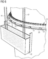
- Figure 6
- shows a zoomed detail of the assembly of
figure 5 . - Figure 7
- illustrates operative steps of a method for mounting a tower for a wind turbine according to the present invention.
- The illustrations in the drawings are schematically. It is noted that in different figures, similar or identical elements are provided with the same reference signs.
-
Figure 1 shows a wind turbine 1 according to the invention. The wind turbine 1 comprises atower 2 axially extending along a longitudinal axis Z of the wind turbine 1. In the following with the term "axial", where not further specified, reference is intended to a direction parallel to the longitudinal axis Z. Anacelle 3 is attached to an upper end of thetower 2. The wind turbine 1 further comprises awind turbine rotor 5 having three blades 4 (in the perspective ofFigure 1 only twoblades 4 are visible). Therotor 5 is attached to thenacelle 3 in order to be rotatable around a rotational axis Y. Thetower 2 comprises a plurality of axially adjacent tower segments (fourtower segments 7a. 7b, 7c, 7d in the embodiment offigure 1 ). Eachtower segment - The wind turbine 1 comprises a concentrated winding
electrical generator 10. Thewind rotor 5 is rotationally coupled with theelectrical generator 10 by means of a rotatable main shaft 9. According to other possible embodiments of the present invention (not represented in the attached figures), thewind rotor 5 is rotationally coupled directly with the electrical generator 10 (direct-drive generator configuration). A schematically depicted bearingassembly 8 is provided in order to hold in place therotor 5. The rotatable main shaft 9 extends along the rotational axis Y. The permanent magnetelectrical generator 10 includes astator 11 and a rotor 12. The rotor 12 is radially external to thestator 11 and is rotatable with respect to thestator 11 about the rotational axis Y. -
Figure 2 shows twotower segments bolts 22. Thebolts 22 join together tworespective flanges 21 provided at the respective axial ends of thetower segments flanges 21 protrude from acylindrical wall 23 of therespective tower segment tower segments tower segments -
Figures 3 and4 show more detailed views of thefirst tower segment 7a. Theother tower segments first tower segment 7a offigure 3 . One or both the axial ends of thefirst tower segment 7a include a respective "T"flange 21. The "T"flange 21 comprises afirst portion 21a protruding inwards, i.e. towards the longitudinal axis Z, and asecond portion 21b protruding outwards, i.e. opposite to the longitudinal axis Z. Holes for connecting thebolts 22 to theflange 21 are provided on both thefirst portion 21a and thesecond portion 21b. Thefirst tower segment 7a comprises arail 20 attached to thesecond portion 21b of theflange 21. Therail 20 is a circular ring coaxial with the longitudinal axis Z and extending for 360° about the longitudinal axis Z. According to other embodiments of the present invention (not shown) therail 20 extends for an angle smaller than 360° about the longitudinal axis Z. According to another embodiment of the present invention (not shown) a rail may be provided also along thefirst portion 21a of theflange 21. Therail 20 is attached to therespective flange 21 by means of a plurality ofsupports 25 regularly distributed about the longitudinal axis Z. The supports 25 are fixed, for example by welding, to both theflange 21 and therail 20. - The
rail 20 provides a guide for attaching aservice trolley 30 to thetower 20. Theservice trolley 30 is attachable in order to be translated along therail 20. Theservice trolley 30 has a curved shape parallel to theguide 20 and extends for an angle smaller than 360° about the longitudinal axis Z. The coupling between theservice trolley 30 and therail 20 may be provided by means of a wheeled connection or any other sliding connection. Therail 20 may be provided at one or both the axial ends of eachtower segment -
Figures 5 and6 show how theservice trolley 30 and therail 20 may be used for operating aservice platform 40 along the external surface of thecylindrical wall 23. A retainingcable 55 is arranged around thetower 2 in a belt configuration and attached to theservice platform 40. The retainingcable 55 reduces movements, in particular lateral movements, of the service platform and improves security and increase the wind speed limit to operate. - In an initial step of a method for mounting the tower 2 a
first tower segment 7a and asecond tower segment 7b identical to each other are provided. Therail 20 is provided at least at a second axial end of thesecond tower segment 7b, i.e. to the axial end of the eachsecond tower segment 7b, which in the assembledtower 2 is distanced from thefirst tower segment 7a. In a following step of the method theservice trolley 30 is attached on therail 20. In a further step of the method, thefirst tower segment 7a and asecond tower segment 7b are axially attached to each other, the first axial end of thesecond tower segment 7b being attached to thefirst tower segment 7a. Thefirst tower segment 7a and thesecond tower segment 7b are fixed to each other by means of a plurality ofblots 22 provided on thefirst portion 21a of therespective flanges 21.Other bolts 22 may be prefixed to thesecond portion 21b of one of theflanges 21 at the interface between the thefirst tower segment 7a and thesecond tower segment 7b. In a further step of the method, aservice platform 40 is attached to theservice trolley 30. Theservice platform 40 may be attached to theservice trolley 30 by means of a lifting apparatus including a plurality ofcables service platform 40 may be attached to theservice trolley 30. The cable may be used to operate theservice platform 40 in a direction parallel to the longitudinal axis Z. The position of theservice platform 40 about the longitudinal axis Z can be varied by sliding theservice trolley 30 along therail 20. In a further step of the method, theservice platform 40 is used by operators for fixing the plurality ofblots 22 on thesecond portion 21b of theflanges 21 at the interface between the thefirst tower segment 7a and thesecond tower segment 7b. -
Figure 7 shows a further step of the method, wherein aparapet clamp 50 is used for removing theservice trolley 30 from the second axial end of thesecond tower segment 7b. In a further step of the method, theservice trolley 30 may be attached to athird tower segment 7c for attaching thethird tower segment 7c to thesecond tower segment 7b in an analogous way to that above described for thefirst tower segment 7a and thesecond tower segment 7b. - According to other embodiments of the present invention, the
rail 20 may be used for performing other service and maintenance operations on the external surface of thetower 2. - According to other embodiments of the present invention (not shown) the
rail 20 may be provided at an intermediate axial position between the two axial ends of atower segment - According to other embodiments of the present invention (not shown) the
rail 20 may be provided on the external surface of atower 2 for a wind turbine not having an axially segmented structure.
Claims (13)
- A tower (2) for a wind turbine (1) extending axially along a longitudinal axis (Z) of the wind turbine (1),
wherein the tower (2) comprises a rail (20) attached to an external surface of the tower (2), the rail (20) providing a guide to which a service trolley (30) is attachable in order to be movable along the rail (20). - The tower (2) according to claim 1, wherein the rail (20) is curved.
- The tower (2) according to claim 2, wherein the rail (20) is coaxial with the longitudinal axis (Z) of the wind turbine (1).
- The tower (2) according to claim 3, wherein the rail (20) extends for 360° about the longitudinal axis (Z) of the wind turbine (1).
- The tower (2) according to any of the previous claims, wherein the tower (2) further comprises a plurality of axially adjacent tower segments (7a, 7b, 7c, 7d), the rail (20) being provided at one interface between two adjacent tower segments (7a, 7b, 7c, 7d).
- The tower (2) according to claim 5, wherein each tower segment (7a, 7b, 7c, 7d) extends axially between two axial ends, the rail (20) being provided at one or both of said axial ends.
- The tower (2) according to claim 6, wherein a respective flange (21) is provided at one or both of said axial ends for connecting the respective tower segment (7a, 7b, 7c, 7d) to another tower segment (7a, 7b, 7c, 7d).
- The tower (2) according to claim 6, wherein the flange (21) is of the "T" type.
- Assembly (100) including a tower (2) for a wind turbine (1) according to any of the previous claims and a service trolley (30) attached to the rail in order to be movable along the rail.
- The assembly (100) according to claim 9, wherein the assembly further includes a service platform (40) and a lifting apparatus (41, 42) for operating the service platform (40) along an external surface of the tower (2), the lifting apparatus (41, 42) connecting the service platform (40) to the service trolley (30).
- The assembly (100) according to claim 10, wherein the lifting apparatus comprises a plurality of cables (41, 42).
- Method for mounting a tower (2) for a wind turbine (1) including the steps of:providing at least a first tower segment (7a) and a second tower segment (7b), each tower segments (7a, 7b) extending axially between a first and a second axial end, a rail (20) being provided at least at the second axial end of the second tower segment (7b),attaching a service trolley (30) on the rail (20) in order to be movable along the rail (20),attaching the second axial end of the first tower segment (7a) to the first axial end of the second tower segment (2b),fixing the first tower segment (7a) and the second tower segment (7b) to each other on an inner side of the first tower segment (7a) and the second tower segment (7b),attaching a service platform (40) to the service trolley (30),using the service platform (40) for fixing the first tower segment (7a) and the second tower segment (7b) to each other on an outer side of the first tower segment (7a) and the second tower segment (7b).
- The method according to claim 12, wherein the service platform (40) is attached to the service trolley (30) and operated by means of a lifting apparatus (41, 42) including a plurality of cables.
Priority Applications (5)
| Application Number | Priority Date | Filing Date | Title |
|---|---|---|---|
| EP19380015.8A EP3772585A1 (en) | 2019-08-09 | 2019-08-09 | Tower for a wind turbine |
| DK20754651.6T DK4010587T3 (en) | 2019-08-09 | 2020-07-28 | TOWER FOR A WINDMILL |
| EP20754651.6A EP4010587B1 (en) | 2019-08-09 | 2020-07-28 | Tower for a wind turbine |
| US17/633,295 US20220282710A1 (en) | 2019-08-09 | 2020-07-28 | Tower for a wind turbine |
| PCT/EP2020/071206 WO2021028212A1 (en) | 2019-08-09 | 2020-07-28 | Tower for a wind turbine |
Applications Claiming Priority (1)
| Application Number | Priority Date | Filing Date | Title |
|---|---|---|---|
| EP19380015.8A EP3772585A1 (en) | 2019-08-09 | 2019-08-09 | Tower for a wind turbine |
Publications (1)
| Publication Number | Publication Date |
|---|---|
| EP3772585A1 true EP3772585A1 (en) | 2021-02-10 |
Family
ID=67777273
Family Applications (2)
| Application Number | Title | Priority Date | Filing Date |
|---|---|---|---|
| EP19380015.8A Withdrawn EP3772585A1 (en) | 2019-08-09 | 2019-08-09 | Tower for a wind turbine |
| EP20754651.6A Active EP4010587B1 (en) | 2019-08-09 | 2020-07-28 | Tower for a wind turbine |
Family Applications After (1)
| Application Number | Title | Priority Date | Filing Date |
|---|---|---|---|
| EP20754651.6A Active EP4010587B1 (en) | 2019-08-09 | 2020-07-28 | Tower for a wind turbine |
Country Status (4)
| Country | Link |
|---|---|
| US (1) | US20220282710A1 (en) |
| EP (2) | EP3772585A1 (en) |
| DK (1) | DK4010587T3 (en) |
| WO (1) | WO2021028212A1 (en) |
Citations (5)
| Publication number | Priority date | Publication date | Assignee | Title |
|---|---|---|---|---|
| WO2012119963A1 (en) * | 2011-03-04 | 2012-09-13 | Inneo Torres, S.L. | Method for accessing the outer surface of wind turbine towers and device for use with this method |
| KR20120114981A (en) * | 2011-04-08 | 2012-10-17 | 대우조선해양 주식회사 | Wind turbine with movable means |
| KR101225690B1 (en) * | 2011-09-02 | 2013-01-23 | 삼성중공업 주식회사 | Movable monitoring robot, and wind power generator having the same, and method for monitoring fastening condition of wind power generator tower segment connecting element using movable monitoring robot |
| WO2014150950A2 (en) * | 2013-03-15 | 2014-09-25 | Chin Howard M | Weather maintenance system for an offshore wind turbine maintenance program |
| EP3260409A1 (en) * | 2016-06-21 | 2017-12-27 | Daniel E. Davis | Method of assembling a wind turbine |
-
2019
- 2019-08-09 EP EP19380015.8A patent/EP3772585A1/en not_active Withdrawn
-
2020
- 2020-07-28 DK DK20754651.6T patent/DK4010587T3/en active
- 2020-07-28 US US17/633,295 patent/US20220282710A1/en active Pending
- 2020-07-28 EP EP20754651.6A patent/EP4010587B1/en active Active
- 2020-07-28 WO PCT/EP2020/071206 patent/WO2021028212A1/en unknown
Patent Citations (5)
| Publication number | Priority date | Publication date | Assignee | Title |
|---|---|---|---|---|
| WO2012119963A1 (en) * | 2011-03-04 | 2012-09-13 | Inneo Torres, S.L. | Method for accessing the outer surface of wind turbine towers and device for use with this method |
| KR20120114981A (en) * | 2011-04-08 | 2012-10-17 | 대우조선해양 주식회사 | Wind turbine with movable means |
| KR101225690B1 (en) * | 2011-09-02 | 2013-01-23 | 삼성중공업 주식회사 | Movable monitoring robot, and wind power generator having the same, and method for monitoring fastening condition of wind power generator tower segment connecting element using movable monitoring robot |
| WO2014150950A2 (en) * | 2013-03-15 | 2014-09-25 | Chin Howard M | Weather maintenance system for an offshore wind turbine maintenance program |
| EP3260409A1 (en) * | 2016-06-21 | 2017-12-27 | Daniel E. Davis | Method of assembling a wind turbine |
Also Published As
| Publication number | Publication date |
|---|---|
| US20220282710A1 (en) | 2022-09-08 |
| DK4010587T3 (en) | 2023-07-31 |
| WO2021028212A1 (en) | 2021-02-18 |
| EP4010587A1 (en) | 2022-06-15 |
| EP4010587B1 (en) | 2023-06-07 |
Similar Documents
| Publication | Publication Date | Title |
|---|---|---|
| EP2520796B1 (en) | Lightning protection system for a wind turbine and method for protecting components of a wind turbine against lightning strikes | |
| US8528735B2 (en) | Transport frame for nacelle/rotor hub unit of a wind turbine, method of transporting and mounting a nacelle/rotor hub unit | |
| CN102232146B (en) | Wind power generation device and maintenance method for same | |
| EP2604851B1 (en) | A wind turbine nacelle cover and a method for installing a generator on a mainframe in a nacelle | |
| CN110635585B (en) | Stator assembly, generator and wind turbine for generating electrical power | |
| EP2775137B1 (en) | System and method for re-indexing a pitch bearing of a wind turbine | |
| US11073134B2 (en) | Hoisting accessories for wind turbines, kits and methods | |
| EP2211443A1 (en) | Manufacturing of segments with special end coils for cross-segment connection | |
| WO2012075607A1 (en) | Methods and systems for assembling wind turbine tower | |
| EP3772585A1 (en) | Tower for a wind turbine | |
| US10285556B2 (en) | System for assembling and/or disassembling a wind turbine electric generator | |
| EP2778389A1 (en) | Tool for mounting rotor blades on a rotor hub, offshore construction device and method of assembling a wind generator | |
| EP3690235B1 (en) | Lifting apparatus for an offshore wind turbine | |
| CN111386651B (en) | Stator assembly, generator and wind turbine | |
| CN107528429B (en) | Removing and installing stator components of a wind turbine generator via a wind turbine hub | |
| CN109416016B (en) | Wind turbine comprising a parking structure for carrying a rotor during removal of a nacelle | |
| US9777705B2 (en) | Method for re-indexing a pitch bearing of a wind turbine | |
| EP3825546B1 (en) | System and method for installing and servicing a jointed rotor blade of a wind turbine | |
| US11492840B2 (en) | Tower segment and manufacturing method | |
| EP3226384A1 (en) | Rotational movement control of an electric generator by means of a turning device | |
| EP3800349A1 (en) | Busbar arrangement for wind turbine generator | |
| EP3453870B1 (en) | Hub and spinner for a wind turbine | |
| CN220527367U (en) | Rotor assembly of collecting ring, collecting ring and wind generating set | |
| CN112012890B (en) | Connecting assembly, stay cable type tower and wind generating set | |
| CN117813250A (en) | Improved construction and maintenance of wind turbines |
Legal Events
| Date | Code | Title | Description |
|---|---|---|---|
| STAA | Information on the status of an ep patent application or granted ep patent |
Free format text: STATUS: UNKNOWN |
|
| PUAI | Public reference made under article 153(3) epc to a published international application that has entered the european phase |
Free format text: ORIGINAL CODE: 0009012 |
|
| STAA | Information on the status of an ep patent application or granted ep patent |
Free format text: STATUS: THE APPLICATION HAS BEEN PUBLISHED |
|
| AK | Designated contracting states |
Kind code of ref document: A1 Designated state(s): AL AT BE BG CH CY CZ DE DK EE ES FI FR GB GR HR HU IE IS IT LI LT LU LV MC MK MT NL NO PL PT RO RS SE SI SK SM TR |
|
| AX | Request for extension of the european patent |
Extension state: BA ME |
|
| STAA | Information on the status of an ep patent application or granted ep patent |
Free format text: STATUS: THE APPLICATION IS DEEMED TO BE WITHDRAWN |
|
| 18D | Application deemed to be withdrawn |
Effective date: 20210811 |