EP3772430A1 - A seat for a vehicle - Google Patents
A seat for a vehicle Download PDFInfo
- Publication number
- EP3772430A1 EP3772430A1 EP20187150.6A EP20187150A EP3772430A1 EP 3772430 A1 EP3772430 A1 EP 3772430A1 EP 20187150 A EP20187150 A EP 20187150A EP 3772430 A1 EP3772430 A1 EP 3772430A1
- Authority
- EP
- European Patent Office
- Prior art keywords
- seat
- seat back
- back portion
- projecting portion
- projecting
- Prior art date
- Legal status (The legal status is an assumption and is not a legal conclusion. Google has not performed a legal analysis and makes no representation as to the accuracy of the status listed.)
- Granted
Links
Images


Classifications
-
- B—PERFORMING OPERATIONS; TRANSPORTING
- B60—VEHICLES IN GENERAL
- B60N—SEATS SPECIALLY ADAPTED FOR VEHICLES; VEHICLE PASSENGER ACCOMMODATION NOT OTHERWISE PROVIDED FOR
- B60N2/00—Seats specially adapted for vehicles; Arrangement or mounting of seats in vehicles
- B60N2/02—Seats specially adapted for vehicles; Arrangement or mounting of seats in vehicles the seat or part thereof being movable, e.g. adjustable
- B60N2/20—Seats specially adapted for vehicles; Arrangement or mounting of seats in vehicles the seat or part thereof being movable, e.g. adjustable the back-rest being tiltable, e.g. to permit easy access
- B60N2/206—Seats specially adapted for vehicles; Arrangement or mounting of seats in vehicles the seat or part thereof being movable, e.g. adjustable the back-rest being tiltable, e.g. to permit easy access to a position in which it can be used as a support for objects, e.g. as a tray
-
- B—PERFORMING OPERATIONS; TRANSPORTING
- B60—VEHICLES IN GENERAL
- B60N—SEATS SPECIALLY ADAPTED FOR VEHICLES; VEHICLE PASSENGER ACCOMMODATION NOT OTHERWISE PROVIDED FOR
- B60N2/00—Seats specially adapted for vehicles; Arrangement or mounting of seats in vehicles
- B60N2/02—Seats specially adapted for vehicles; Arrangement or mounting of seats in vehicles the seat or part thereof being movable, e.g. adjustable
- B60N2/22—Seats specially adapted for vehicles; Arrangement or mounting of seats in vehicles the seat or part thereof being movable, e.g. adjustable the back-rest being adjustable
-
- B—PERFORMING OPERATIONS; TRANSPORTING
- B60—VEHICLES IN GENERAL
- B60N—SEATS SPECIALLY ADAPTED FOR VEHICLES; VEHICLE PASSENGER ACCOMMODATION NOT OTHERWISE PROVIDED FOR
- B60N2/00—Seats specially adapted for vehicles; Arrangement or mounting of seats in vehicles
- B60N2/02—Seats specially adapted for vehicles; Arrangement or mounting of seats in vehicles the seat or part thereof being movable, e.g. adjustable
- B60N2/22—Seats specially adapted for vehicles; Arrangement or mounting of seats in vehicles the seat or part thereof being movable, e.g. adjustable the back-rest being adjustable
- B60N2/2222—Seats specially adapted for vehicles; Arrangement or mounting of seats in vehicles the seat or part thereof being movable, e.g. adjustable the back-rest being adjustable the back-rest having two or more parts
-
- B—PERFORMING OPERATIONS; TRANSPORTING
- B60—VEHICLES IN GENERAL
- B60N—SEATS SPECIALLY ADAPTED FOR VEHICLES; VEHICLE PASSENGER ACCOMMODATION NOT OTHERWISE PROVIDED FOR
- B60N2/00—Seats specially adapted for vehicles; Arrangement or mounting of seats in vehicles
- B60N2/24—Seats specially adapted for vehicles; Arrangement or mounting of seats in vehicles for particular purposes or particular vehicles
- B60N2/30—Non-dismountable or dismountable seats storable in a non-use position, e.g. foldable spare seats
- B60N2/3002—Non-dismountable or dismountable seats storable in a non-use position, e.g. foldable spare seats back-rest movements
- B60N2/3004—Non-dismountable or dismountable seats storable in a non-use position, e.g. foldable spare seats back-rest movements by rotation only
- B60N2/3009—Non-dismountable or dismountable seats storable in a non-use position, e.g. foldable spare seats back-rest movements by rotation only about transversal axis
-
- B—PERFORMING OPERATIONS; TRANSPORTING
- B60—VEHICLES IN GENERAL
- B60N—SEATS SPECIALLY ADAPTED FOR VEHICLES; VEHICLE PASSENGER ACCOMMODATION NOT OTHERWISE PROVIDED FOR
- B60N2/00—Seats specially adapted for vehicles; Arrangement or mounting of seats in vehicles
- B60N2/24—Seats specially adapted for vehicles; Arrangement or mounting of seats in vehicles for particular purposes or particular vehicles
- B60N2/32—Seats specially adapted for vehicles; Arrangement or mounting of seats in vehicles for particular purposes or particular vehicles convertible for other use
-
- B—PERFORMING OPERATIONS; TRANSPORTING
- B60—VEHICLES IN GENERAL
- B60N—SEATS SPECIALLY ADAPTED FOR VEHICLES; VEHICLE PASSENGER ACCOMMODATION NOT OTHERWISE PROVIDED FOR
- B60N2/00—Seats specially adapted for vehicles; Arrangement or mounting of seats in vehicles
- B60N2/58—Seat coverings
- B60N2/60—Removable protective coverings
- B60N2/6009—Removable protective coverings covering more than only the seat
-
- B—PERFORMING OPERATIONS; TRANSPORTING
- B60—VEHICLES IN GENERAL
- B60N—SEATS SPECIALLY ADAPTED FOR VEHICLES; VEHICLE PASSENGER ACCOMMODATION NOT OTHERWISE PROVIDED FOR
- B60N2/00—Seats specially adapted for vehicles; Arrangement or mounting of seats in vehicles
- B60N2/64—Back-rests or cushions
-
- B—PERFORMING OPERATIONS; TRANSPORTING
- B60—VEHICLES IN GENERAL
- B60N—SEATS SPECIALLY ADAPTED FOR VEHICLES; VEHICLE PASSENGER ACCOMMODATION NOT OTHERWISE PROVIDED FOR
- B60N3/00—Arrangements or adaptations of other passenger fittings, not otherwise provided for
- B60N3/001—Arrangements or adaptations of other passenger fittings, not otherwise provided for of tables or trays
-
- B—PERFORMING OPERATIONS; TRANSPORTING
- B60—VEHICLES IN GENERAL
- B60N—SEATS SPECIALLY ADAPTED FOR VEHICLES; VEHICLE PASSENGER ACCOMMODATION NOT OTHERWISE PROVIDED FOR
- B60N3/00—Arrangements or adaptations of other passenger fittings, not otherwise provided for
- B60N3/001—Arrangements or adaptations of other passenger fittings, not otherwise provided for of tables or trays
- B60N3/002—Arrangements or adaptations of other passenger fittings, not otherwise provided for of tables or trays of trays
- B60N3/004—Arrangements or adaptations of other passenger fittings, not otherwise provided for of tables or trays of trays of foldable trays mounted on the back-rest
Definitions
- This disclosure relates generally to a seat for a vehicle and particularly, although not exclusively, relates to a seat back with a protruding portion that protrudes below a pivot point of the seat and provides a table surface when the seat back is rotated.
- Utility vehicles have to perform various functions, one of which is as a mobile office. However, the interior of utility vehicles is often not suitable for carrying out paperwork.
- a seat for a vehicle comprising:
- the seat back portion may rotate about a pivot point of the seat.
- the back surface of the seat back portion may be above the pivot point and the projecting portion may be below the pivot point.
- the projecting portion may be rigidly fixed to the seat back portion.
- the projecting portion may be moveable with respect to the seat back portion, for example, the projecting portion may be retractable into the seat back portion.
- the seat back portion may be rotatably coupled to the seat base portion, e.g. at the pivot point of the seat.
- the seat may further comprise an intermediate seat back portion provided between the seat back portion and the seat base portion.
- the seat back portion may be rotatably coupled to the intermediate seat back portion, e.g. at the pivot point of the seat.
- the intermediate seat back portion may be rotatably coupled to the seat base portion. For example, the intermediate seat back portion and seat back portion may together rotate with respect to the seat base portion.
- the seat may further comprise at least one selectively extending portion.
- the extending portion may be configured to further extend the table surface.
- the or each extending portion may selectively extend from the projecting portion. For example, the or each extending portion may unfold with respect to the projecting portion.
- the seat may comprise a pair of extending portions that extend from the projecting portion.
- the pair of extending portions may extend from respective lateral edges of the projecting portion.
- the pair of extending portions may rotate about respective lateral edges of the projecting portion and may unfold with respect to the projecting portion.
- the seat may further comprise a headrest portion.
- the headrest portion may be configured to engage a dashboard structure of the vehicle when the seat is in the second position.
- a vehicle comprising the aforementioned seat.
- the vehicle may further comprise at least one further seat.
- the further seat may be provided adjacent to the seat.
- the extending portion when deployed may extend behind the further seat.
- the vehicle may further comprise the dashboard structure.
- the dashboard structure may be configured to receive the headrest portion and hold the seat back portion in place when in the second position.
- the vehicle may further comprise a rear seat provided rearwards of the seat.
- the table surface may be provided for an occupant of the rear seat.
- the present disclosure relates to a seat 10 for a vehicle 100, such as a motor vehicle.
- the seat 10 comprises a seat base portion 20 and a seat back portion 30.
- the seat back portion 30 is rotatable with respect to the seat base portion 20.
- the seat back portion 30 is rotatable between a first position, in which the seat back portion is substantially upright (depicted in Figure 1a ), and a second position, in which a back surface 31 of the seat back portion is substantially horizontal (depicted in Figure 1b ).
- the seat back portion 30 may be rotatably coupled to the seat base portion 20 at a pivot point 22.
- the seat 10 may further comprise an intermediate seat back portion 32 provided between the seat back portion 30 and the seat base portion 20.
- the intermediate seat back portion 32 and the seat back portion 30 may together form a seat back of the seat 10.
- the seat back portion 30 may be rotatably coupled to the intermediate seat back portion 32, e.g. at the pivot point 22.
- the intermediate seat back portion 32 may also be rotatably coupled to the seat base portion 20 about a further pivot point 24.
- the intermediate seat back portion 32 and seat back portion 30 may together rotate with respect to the seat base portion 20, e.g. to allow adjustment of the seat back recline angle.
- the intermediate seat back portion 32 may be omitted and the seat back portion 30 may directly couple to the seat base portion 20.
- the seat 10 further comprises a projecting portion 40.
- the projecting portion 40 extends from a lower edge 34 of the seat back portion 30.
- the lower edge 34 is at a lower end of the seat back portion 30 when it is in the first position.
- the projecting portion 40 is configured to rotate with the seat back portion 30 about pivot point 22.
- the back surface 31 of the seat back portion may be above the pivot point 22 and the projecting portion 40 may be below the pivot point 22.
- the back surface 31 of the seat back portion and the projecting portion 40 may be either side of the pivot point 22 with the projecting portion 40 extending rearwards of the seat base portion 30.
- the projecting portion 40 has a surface 42 that is contiguous with the back surface 31 of the seat back portion 30.
- the projecting portion surface 42 is continuous with the back surface 31.
- the projecting portion surface 42 and the back surface 31 may be substantially flat and may lie in substantially the same plane.
- the back surface 31 of the seat back portion and the surface 42 of the projecting portion 40 together form a table surface when the seat back portion 30 is in the second position.
- the projecting portion 40 is rigidly fixed to the seat back portion 30.
- the projecting portion 40 may be moveable with respect to the seat back portion 30.
- the projecting portion 40 may be retractable into the seat back portion 30.
- the projecting portion 40 may retract into the seat back portion 30 when the seat back portion 30 is in the first position and the projecting portion 40 may extend from the seat back portion 30 when the seat back portion 30 is in the second position.
- the seat 10 may further comprise a headrest portion 50 extending from an upper edge 35 of the seat back portion 30.
- the headrest portion 50 may engage a dashboard structure 60 of the vehicle when the seat back portion 30 is in the second position.
- the dashboard structure 60 may be configured to receive the headrest portion 50 and hold the seat back portion 30 in place when it is in the second position.
- the dashboard structure may comprise a recess or receiving section that receives the headrest portion 50. An interaction with the dashboard structure 60 may resist further rotation of the seat back portion 30 and may help provide a stable table surface.
- the seat 10 may be provided in the vehicle 100 as part of a row of seats.
- the seat 10 may be a middle seat 10b in a row of three seats 10a, 10b, 10c.
- the seat 10 may be provided in a row of one or more seats.
- the vehicle 100 may further comprise one or more rear seats provided behind the seat 10.
- a row of three rear seats 70a, 70b, 70c are provided behind the seat 10.
- one or more rear seats may be provided behind seat 10.
- the table surface provided by the seat 10 when the seat back portion 30 is in the second position may be used by an occupant of one of the rear seats 70a, 70b, 70c and/or an occupant of one of the front seats 10a, 10c.
- the vehicle 100 may comprise the dashboard structure 60. As shown in Figure 2b , the headrest portion of seat 10 may engage (e.g. rest on) the dashboard structure 60 when the seat back portion 30 is in the second position. A locking mechanism (not shown) may be provided to secure the seat back portion 30 in the second position.
- the seat 10 may comprise a pair of extending portions 80a, 80b that selectively extend from the projecting portion 40.
- the pair of extending portions 80a, 80b may extend from respective opposite lateral edges 43, 44 of the projecting portion 40.
- the pair of extending portions 80a, 80b may rotate about the respective lateral edges 43, 44 of the projecting portion 40 and may unfold with respect to the projecting portion.
- the extending portions 80a, 80b when deployed may extend behind the other front row seats 10a, 10c.
- the extending portions 80a, 80b may fold back onto the projecting portion 40 and may or may not overlap when folded back.
- a locking mechanism (not shown) may hold the extending portions 80a, 80b in place when extended and/or stowed.
- the extending portions 80a, 80b and protruding portion 40 may together rotate with the seat back portion 30, e.g. when returning to or moving away from the first position depicted in Figures 1a and 2a .
- one or more extending portions may be provided. Furthermore, the extending portion(s) may retract, e.g. slide, relative to the protruding portion 40.
- the seat 10 of the present disclosure advantageously provides a large table surface for an occupant of the vehicle 100 to use. This may be particularly beneficial when the vehicle is being used as a mobile office.
Landscapes
- Engineering & Computer Science (AREA)
- Transportation (AREA)
- Mechanical Engineering (AREA)
- Aviation & Aerospace Engineering (AREA)
- Seats For Vehicles (AREA)
- Passenger Equipment (AREA)
Abstract
Description
- This disclosure relates generally to a seat for a vehicle and particularly, although not exclusively, relates to a seat back with a protruding portion that protrudes below a pivot point of the seat and provides a table surface when the seat back is rotated.
- Utility vehicles have to perform various functions, one of which is as a mobile office. However, the interior of utility vehicles is often not suitable for carrying out paperwork.
- According to an aspect of the present disclosure, there is provided a seat for a vehicle (such as a motor vehicle), the seat comprising:
- a seat base portion;
- a seat back portion rotatable with respect to the seat base portion between a first position, in which the seat back portion is substantially upright, and a second position, in which a back surface of the seat back portion is substantially horizontal, and
- a projecting portion extending from an edge of the seat back portion that is at a lower end of the seat back portion when in the first position, the projecting portion having a surface that is contiguous with the back surface of the seat back portion, wherein the projecting portion is configured to rotate with the seat back portion such that in the second position the projecting portion extends rearwards of the seat base portion and the back surface of the seat back portion and the surface of the projecting portion together form a table surface.
- The seat back portion may rotate about a pivot point of the seat. When the seat back portion is in the first position, the back surface of the seat back portion may be above the pivot point and the projecting portion may be below the pivot point.
- The projecting portion may be rigidly fixed to the seat back portion. Alternatively, the projecting portion may be moveable with respect to the seat back portion, for example, the projecting portion may be retractable into the seat back portion.
- The seat back portion may be rotatably coupled to the seat base portion, e.g. at the pivot point of the seat.
- The seat may further comprise an intermediate seat back portion provided between the seat back portion and the seat base portion. The seat back portion may be rotatably coupled to the intermediate seat back portion, e.g. at the pivot point of the seat. The intermediate seat back portion may be rotatably coupled to the seat base portion. For example, the intermediate seat back portion and seat back portion may together rotate with respect to the seat base portion.
- The seat may further comprise at least one selectively extending portion. The extending portion may be configured to further extend the table surface. The or each extending portion may selectively extend from the projecting portion. For example, the or each extending portion may unfold with respect to the projecting portion.
- The seat may comprise a pair of extending portions that extend from the projecting portion. The pair of extending portions may extend from respective lateral edges of the projecting portion. For example, the pair of extending portions may rotate about respective lateral edges of the projecting portion and may unfold with respect to the projecting portion.
- The seat may further comprise a headrest portion. The headrest portion may be configured to engage a dashboard structure of the vehicle when the seat is in the second position.
- According to another aspect of the present disclosure there is provided a vehicle comprising the aforementioned seat.
- The vehicle may further comprise at least one further seat. The further seat may be provided adjacent to the seat. The extending portion when deployed may extend behind the further seat.
- The vehicle may further comprise the dashboard structure. The dashboard structure may be configured to receive the headrest portion and hold the seat back portion in place when in the second position.
- The vehicle may further comprise a rear seat provided rearwards of the seat. The table surface may be provided for an occupant of the rear seat.
- To avoid unnecessary duplication of effort and repetition of text in the specification, certain features are described in relation to only one or several aspects or embodiments of the invention. However, it is to be understood that, where it is technically possible, features described in relation to any aspect or embodiment of the invention may also be used with any other aspect or embodiment of the invention.
- For a better understanding of the present invention, and to show more clearly how it may be carried into effect, reference will now be made, by way of example, to the accompanying drawings, in which:
-
Figures 1a and 1b (collectivelyFigure 1 ) are schematic side views of a seat for a vehicle according to an example of the present disclosure withFigure 1a showing a seat back in a first position andFigure 1b showing the seat back in a second position; and -
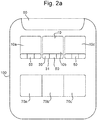
Figures 2a and2b (collectivelyFigure 2 ) are schematic top views of a seating arrangement for a vehicle according to an example of the present disclosure withFigure 2a showing a seat back of one of the seats in the first position andFigure 2b showing the seat back in the second position. - With reference to
Figure 1 , the present disclosure relates to aseat 10 for avehicle 100, such as a motor vehicle. Theseat 10 comprises aseat base portion 20 and aseat back portion 30. Theseat back portion 30 is rotatable with respect to theseat base portion 20. In particular, theseat back portion 30 is rotatable between a first position, in which the seat back portion is substantially upright (depicted inFigure 1a ), and a second position, in which aback surface 31 of the seat back portion is substantially horizontal (depicted inFigure 1b ). As shown, theseat back portion 30 may be rotatably coupled to theseat base portion 20 at apivot point 22. - The
seat 10 may further comprise an intermediateseat back portion 32 provided between theseat back portion 30 and theseat base portion 20. The intermediate seat backportion 32 and the seat backportion 30 may together form a seat back of theseat 10. Theseat back portion 30 may be rotatably coupled to the intermediateseat back portion 32, e.g. at thepivot point 22. The intermediateseat back portion 32 may also be rotatably coupled to theseat base portion 20 about afurther pivot point 24. For example, the intermediate seat backportion 32 andseat back portion 30 may together rotate with respect to theseat base portion 20, e.g. to allow adjustment of the seat back recline angle. In another arrangement (not shown), the intermediateseat back portion 32 may be omitted and the seat backportion 30 may directly couple to theseat base portion 20. - The
seat 10 further comprises a projectingportion 40. The projectingportion 40 extends from alower edge 34 of theseat back portion 30. Thelower edge 34 is at a lower end of the seat backportion 30 when it is in the first position. The projectingportion 40 is configured to rotate with the seat backportion 30 aboutpivot point 22. When the seat backportion 30 is in the first position, theback surface 31 of the seat back portion may be above thepivot point 22 and the projectingportion 40 may be below thepivot point 22. By contrast, when the seat backportion 30 is in the second position, theback surface 31 of the seat back portion and the projectingportion 40 may be either side of thepivot point 22 with the projectingportion 40 extending rearwards of theseat base portion 30. - The projecting
portion 40 has asurface 42 that is contiguous with theback surface 31 of theseat back portion 30. The projectingportion surface 42 is continuous with theback surface 31. In particular, the projectingportion surface 42 and theback surface 31 may be substantially flat and may lie in substantially the same plane. Theback surface 31 of the seat back portion and thesurface 42 of the projectingportion 40 together form a table surface when the seat backportion 30 is in the second position. - In the depicted arrangement, the projecting
portion 40 is rigidly fixed to the seat backportion 30. However, in another arrangement (not shown), the projectingportion 40 may be moveable with respect to the seat backportion 30. For example, the projectingportion 40 may be retractable into the seat backportion 30. In particular, the projectingportion 40 may retract into the seat backportion 30 when the seat backportion 30 is in the first position and the projectingportion 40 may extend from the seat backportion 30 when the seat backportion 30 is in the second position. - With reference to
Figure 1b , theseat 10 may further comprise aheadrest portion 50 extending from anupper edge 35 of the seat backportion 30. Theheadrest portion 50 may engage adashboard structure 60 of the vehicle when the seat backportion 30 is in the second position. Thedashboard structure 60 may be configured to receive theheadrest portion 50 and hold the seat backportion 30 in place when it is in the second position. For example, the dashboard structure may comprise a recess or receiving section that receives theheadrest portion 50. An interaction with thedashboard structure 60 may resist further rotation of the seat backportion 30 and may help provide a stable table surface. - With reference to
Figure 2 , theseat 10 may be provided in thevehicle 100 as part of a row of seats. In the particular arrangement shown, theseat 10 may be amiddle seat 10b in a row of threeseats seat 10 may be provided in a row of one or more seats. - The
vehicle 100 may further comprise one or more rear seats provided behind theseat 10. In the particular arrangement shown, a row of threerear seats seat 10. However, it is also envisaged that one or more rear seats may be provided behindseat 10. - The table surface provided by the
seat 10 when the seat backportion 30 is in the second position may be used by an occupant of one of therear seats front seats - The
vehicle 100 may comprise thedashboard structure 60. As shown inFigure 2b , the headrest portion ofseat 10 may engage (e.g. rest on) thedashboard structure 60 when the seat backportion 30 is in the second position. A locking mechanism (not shown) may be provided to secure the seat backportion 30 in the second position. - As depicted in
Figure 2b , theseat 10 may comprise a pair of extendingportions portion 40. The pair of extendingportions lateral edges portion 40. For example, the pair of extendingportions portion 40 and may unfold with respect to the projecting portion. The extendingportions front row seats - The extending
portions portion 40 and may or may not overlap when folded back. A locking mechanism (not shown) may hold the extendingportions portions portion 40 may together rotate with the seat backportion 30, e.g. when returning to or moving away from the first position depicted inFigures 1a and2a . - In other arrangements (not shown), one or more extending portions may be provided. Furthermore, the extending portion(s) may retract, e.g. slide, relative to the protruding
portion 40. - The
seat 10 of the present disclosure advantageously provides a large table surface for an occupant of thevehicle 100 to use. This may be particularly beneficial when the vehicle is being used as a mobile office. - The following numbered statements form part of the present disclosure:
- Statement 1. A seat for a vehicle, the seat comprising:
- a seat base portion;
- a seat back portion rotatable with respect to the seat base portion between a first position, in which the seat back portion is substantially upright, and a second position, in which a back surface of the seat back portion is substantially horizontal, and
- a projecting portion extending from an edge of the seat back portion that is at a lower end of the seat back portion when in the first position, the projecting portion having a surface that is contiguous with the back surface of the seat back portion, wherein the projecting portion is configured to rotate with the seat back portion such that in the second position the projecting portion extends rearwards of the seat base portion and the back surface of the seat back portion and the surface of the projecting portion together form a table surface.
- Statement 2. The seat of statement 1, wherein the seat back portion rotates about a pivot point of the seat and when the seat back portion is in the first position, the back surface of the seat back portion is above the pivot point and the projecting portion is below the pivot point.
- Statement 3. The seat of statement 1 or 2, wherein the projecting portion is rigidly fixed to the seat back portion.
- Statement 4. The seat of statement 1 or 2, wherein the projecting portion is retractable into the seat back portion.
- Statement 5. The seat of any of the preceding statements, wherein the seat back portion is rotatably coupled to the seat base portion.
- Statement 6. The seat of any of statements 1 to 4, wherein the seat further comprises an intermediate seat back portion provided between the seat back portion and the seat base portion.
- Statement 7. The seat of statement 6, wherein the seat back portion is rotatably coupled to the intermediate seat back portion.
- Statement 8. The seat of statement 6 or 7, wherein the intermediate seat back portion is rotatably coupled to the seat base portion.
- Statement 9. The seat of any of the preceding statements, wherein the seat further comprises at least one selectively extending portion, the extending portion being configured to further extend the table surface.
-
Statement 10. The seat of statement 9, wherein the or each extending portion selectively extends from the projecting portion. - Statement 11. The seat of
statement 9 or 10, wherein the or each extending portion unfolds with respect to the projecting portion. - Statement 12. The seat of any of statements 9 to 11, wherein the seat comprises a pair of extending portions that extend from the projecting portion.
- Statement 13. The seat of statement 12, wherein the pair of extending portions extend from respective lateral edges of the projecting portion.
- Statement 14. The seat of statement 13, wherein the pair of extending portions rotate about respective lateral edges of the projecting portion and unfold with respect to the projecting portion.
- Statement 15. The seat of any of the preceding statements, wherein the seat further comprises a headrest portion, the headrest portion being configured to engage a dashboard structure of the vehicle when the seat is in the second position.
- Statement 16. A vehicle comprising the seat of any of the preceding statements.
- Statement 17. The vehicle of statement 16, wherein the vehicle further comprises at least one further seat, the further seat being provided adjacent to the seat.
- Statement 18. The vehicle of statement 17 when dependent on statement 9, wherein the extending portion when deployed extends behind the further seat.
- Statement 19. The vehicle of any of statements 16 to 18 when dependent on statement 15, wherein the vehicle further comprises the dashboard structure and the dashboard is configured to receive the headrest portion and hold the seat back portion in place when in the second position.
-
Statement 20. The vehicle of any of statements 16 to 19, wherein the vehicle further comprises a rear seat provided rearwards of the seat, the table surface being provided for an occupant of the rear seat. - It will be appreciated by those skilled in the art that although the invention has been described by way of example, with reference to one or more examples, it is not limited to the disclosed examples and alternative examples may be constructed without departing from the scope of the invention as defined by the appended claims.
Claims (15)
- A seat for a vehicle, the seat comprising:a seat base portion;a seat back portion rotatable with respect to the seat base portion between a first position, in which the seat back portion is substantially upright, and a second position, in which a back surface of the seat back portion is substantially horizontal, anda projecting portion extending from an edge of the seat back portion that is at a lower end of the seat back portion when in the first position, the projecting portion having a surface that is contiguous with the back surface of the seat back portion, wherein the projecting portion is configured to rotate with the seat back portion such that in the second position the projecting portion extends rearwards of the seat base portion and the back surface of the seat back portion and the surface of the projecting portion together form a table surface.
- The seat of claim 1, wherein the seat back portion rotates about a pivot point of the seat and when the seat back portion is in the first position, the back surface of the seat back portion is above the pivot point and the projecting portion is below the pivot point.
- The seat of claim 1 or 2, wherein the projecting portion is rigidly fixed to the seat back portion or the projecting portion is retractable into the seat back portion.
- The seat of any of the preceding claims, wherein the seat back portion is rotatably coupled to the seat base portion.
- The seat of any of claims 1 to 3, wherein the seat further comprises an intermediate seat back portion provided between the seat back portion and the seat base portion, wherein the seat back portion is rotatably coupled to the intermediate seat back portion, and wherein the intermediate seat back portion is rotatably coupled to the seat base portion.
- The seat of any of the preceding claims, wherein the seat further comprises at least one selectively extending portion, the extending portion being configured to further extend the table surface.
- The seat of claim 6, wherein the or each extending portion selectively extends from the projecting portion.
- The seat of claim 6 or 7, wherein the or each extending portion unfolds with respect to the projecting portion.
- The seat of any of claims 6 to 8, wherein the seat comprises a pair of extending portions that extend from the projecting portion.
- The seat of claim 9, wherein the pair of extending portions extend from respective lateral edges of the projecting portion.
- The seat of claim 10, wherein the pair of extending portions rotate about respective lateral edges of the projecting portion and unfold with respect to the projecting portion.
- The seat of any of the preceding claims, wherein the seat further comprises a headrest portion, the headrest portion being configured to engage a dashboard structure of the vehicle when the seat is in the second position.
- A vehicle comprising the seat of any of the preceding claims.
- The vehicle of claim 13 when dependent on claim 6, wherein the vehicle further comprises at least one further seat, the further seat being provided adjacent to the seat, wherein the extending portion when deployed extends behind the further seat.
- The vehicle of claim 13 or 14, wherein the vehicle further comprises a rear seat provided rearwards of the seat, the table surface being provided for an occupant of the rear seat.
Applications Claiming Priority (1)
| Application Number | Priority Date | Filing Date | Title |
|---|---|---|---|
| GB1911396.8A GB2586163B (en) | 2019-08-09 | 2019-08-09 | A seat for a vehicle |
Publications (2)
| Publication Number | Publication Date |
|---|---|
| EP3772430A1 true EP3772430A1 (en) | 2021-02-10 |
| EP3772430B1 EP3772430B1 (en) | 2022-06-22 |
Family
ID=67991084
Family Applications (1)
| Application Number | Title | Priority Date | Filing Date |
|---|---|---|---|
| EP20187150.6A Active EP3772430B1 (en) | 2019-08-09 | 2020-07-22 | A seat for a vehicle |
Country Status (3)
| Country | Link |
|---|---|
| EP (1) | EP3772430B1 (en) |
| CN (1) | CN112339623A (en) |
| GB (1) | GB2586163B (en) |
Cited By (1)
| Publication number | Priority date | Publication date | Assignee | Title |
|---|---|---|---|---|
| WO2026122095A1 (en) * | 2024-12-05 | 2026-06-11 | Safran Seats Usa Llc | Semi-fixed back shell for passenger seat |
Citations (5)
| Publication number | Priority date | Publication date | Assignee | Title |
|---|---|---|---|---|
| JPH05221256A (en) * | 1990-12-27 | 1993-08-31 | Hans-Juergen Zaeh | Car seat |
| GB2395118A (en) * | 2002-11-09 | 2004-05-19 | Ford Global Tech Llc | Seat assembly having a table extending from upper backrest |
| DE102005025544A1 (en) * | 2005-06-01 | 2006-12-07 | Johnson Controls Gmbh | Seating device e.g. for motor vehicle, has second row of vehicle seating arranged behind first, which is suitable as supporting surface for legs of passenger present at second vehicle seating |
| WO2011154638A1 (en) * | 2010-06-10 | 2011-12-15 | Peugeot Citroën Automobiles SA | Support device comprising walls that slide in opposite directions on vehicle seat backrests |
| FR3008935A1 (en) * | 2013-07-23 | 2015-01-30 | Peugeot Citroen Automobiles Sa | WRITING TABLET FOR VEHICLE SEAT WITH STORAGE SPACE |
Family Cites Families (5)
| Publication number | Priority date | Publication date | Assignee | Title |
|---|---|---|---|---|
| DE3603891A1 (en) * | 1986-02-07 | 1986-10-16 | Martin Dipl.-Designer 6114 Groß-Umstadt Strobel | Vehicle seat system |
| EP0410814B1 (en) * | 1989-07-28 | 1995-09-13 | Fuji Kiko Company Limited | Automotive seat with walk-in mechanism |
| US6860550B2 (en) * | 2002-11-26 | 2005-03-01 | Daimlerchrysler Corporation | Bucket seat fold out diaper changing table |
| WO2007128843A1 (en) * | 2006-05-08 | 2007-11-15 | Manufacturas Metalicas Del Valle S.L. | Improved retractable support that can be converted into a bed |
| US8109565B2 (en) * | 2008-11-14 | 2012-02-07 | Bright Automotive, Inc. | Automotive seat reconfigurable to work desk |
-
2019
- 2019-08-09 GB GB1911396.8A patent/GB2586163B/en not_active Expired - Fee Related
-
2020
- 2020-07-22 EP EP20187150.6A patent/EP3772430B1/en active Active
- 2020-08-06 CN CN202010781826.1A patent/CN112339623A/en active Pending
Patent Citations (5)
| Publication number | Priority date | Publication date | Assignee | Title |
|---|---|---|---|---|
| JPH05221256A (en) * | 1990-12-27 | 1993-08-31 | Hans-Juergen Zaeh | Car seat |
| GB2395118A (en) * | 2002-11-09 | 2004-05-19 | Ford Global Tech Llc | Seat assembly having a table extending from upper backrest |
| DE102005025544A1 (en) * | 2005-06-01 | 2006-12-07 | Johnson Controls Gmbh | Seating device e.g. for motor vehicle, has second row of vehicle seating arranged behind first, which is suitable as supporting surface for legs of passenger present at second vehicle seating |
| WO2011154638A1 (en) * | 2010-06-10 | 2011-12-15 | Peugeot Citroën Automobiles SA | Support device comprising walls that slide in opposite directions on vehicle seat backrests |
| FR3008935A1 (en) * | 2013-07-23 | 2015-01-30 | Peugeot Citroen Automobiles Sa | WRITING TABLET FOR VEHICLE SEAT WITH STORAGE SPACE |
Cited By (1)
| Publication number | Priority date | Publication date | Assignee | Title |
|---|---|---|---|---|
| WO2026122095A1 (en) * | 2024-12-05 | 2026-06-11 | Safran Seats Usa Llc | Semi-fixed back shell for passenger seat |
Also Published As
| Publication number | Publication date |
|---|---|
| CN112339623A (en) | 2021-02-09 |
| GB201911396D0 (en) | 2019-09-25 |
| GB2586163B (en) | 2021-09-01 |
| GB2586163A (en) | 2021-02-10 |
| EP3772430B1 (en) | 2022-06-22 |
Similar Documents
| Publication | Publication Date | Title |
|---|---|---|
| US8714619B2 (en) | Vehicle seat | |
| EP2930109B1 (en) | A table arrangement | |
| US20080185893A1 (en) | Vehicle seat system | |
| US10189373B2 (en) | Seat arrangement | |
| JP4434075B2 (en) | Vehicle seat moving device | |
| EP2985175B1 (en) | Seat for vehicles | |
| US7377571B2 (en) | Collapsible seat mechanism with integrated subfloor | |
| EP3772430B1 (en) | A seat for a vehicle | |
| JPH05221256A (en) | Car seat | |
| US20100194134A1 (en) | Device for adjusting a motor vehicle seat and motor vehicle seat | |
| ATE370023T1 (en) | MOTOR VEHICLE WITH A FOLDING CENTRAL REAR SEAT AND DIAGONALLY SLIDING SIDE REAR SEATS | |
| JP5604879B2 (en) | Vehicle seat | |
| US12162393B2 (en) | Vehicle having deployable workstation | |
| JP2002104039A (en) | Bounce sheet | |
| JP2003276482A (en) | Rear seat for vehicle | |
| KR100534391B1 (en) | Seat assembly for vehicles | |
| CN211567755U (en) | Foldable headrest | |
| JP6387836B2 (en) | Vehicle seat | |
| EP1972490A1 (en) | Second-row seat for a motor vehicle having a backrest and sitting surface that can both be tipped over | |
| KR101359985B1 (en) | Seat-back tray for vehicle | |
| WO2017203939A1 (en) | Vehicle seat | |
| KR101356938B1 (en) | Vehicle seat | |
| EP1071575A1 (en) | A seat assembly | |
| JP2016147569A (en) | Vehicular seat | |
| JP2026058614A (en) | Vehicle deck board and its leg members |
Legal Events
| Date | Code | Title | Description |
|---|---|---|---|
| PUAI | Public reference made under article 153(3) epc to a published international application that has entered the european phase |
Free format text: ORIGINAL CODE: 0009012 |
|
| STAA | Information on the status of an ep patent application or granted ep patent |
Free format text: STATUS: THE APPLICATION HAS BEEN PUBLISHED |
|
| AK | Designated contracting states |
Kind code of ref document: A1 Designated state(s): AL AT BE BG CH CY CZ DE DK EE ES FI FR GB GR HR HU IE IS IT LI LT LU LV MC MK MT NL NO PL PT RO RS SE SI SK SM TR |
|
| AX | Request for extension of the european patent |
Extension state: BA ME |
|
| STAA | Information on the status of an ep patent application or granted ep patent |
Free format text: STATUS: REQUEST FOR EXAMINATION WAS MADE |
|
| 17P | Request for examination filed |
Effective date: 20210413 |
|
| RBV | Designated contracting states (corrected) |
Designated state(s): AL AT BE BG CH CY CZ DE DK EE ES FI FR GB GR HR HU IE IS IT LI LT LU LV MC MK MT NL NO PL PT RO RS SE SI SK SM TR |
|
| GRAP | Despatch of communication of intention to grant a patent |
Free format text: ORIGINAL CODE: EPIDOSNIGR1 |
|
| STAA | Information on the status of an ep patent application or granted ep patent |
Free format text: STATUS: GRANT OF PATENT IS INTENDED |
|
| GRAJ | Information related to disapproval of communication of intention to grant by the applicant or resumption of examination proceedings by the epo deleted |
Free format text: ORIGINAL CODE: EPIDOSDIGR1 |
|
| STAA | Information on the status of an ep patent application or granted ep patent |
Free format text: STATUS: REQUEST FOR EXAMINATION WAS MADE |
|
| INTG | Intention to grant announced |
Effective date: 20211001 |
|
| INTC | Intention to grant announced (deleted) | ||
| GRAJ | Information related to disapproval of communication of intention to grant by the applicant or resumption of examination proceedings by the epo deleted |
Free format text: ORIGINAL CODE: EPIDOSDIGR1 |
|
| STAA | Information on the status of an ep patent application or granted ep patent |
Free format text: STATUS: GRANT OF PATENT IS INTENDED |
|
| GRAP | Despatch of communication of intention to grant a patent |
Free format text: ORIGINAL CODE: EPIDOSNIGR1 |
|
| INTG | Intention to grant announced |
Effective date: 20220114 |
|
| GRAS | Grant fee paid |
Free format text: ORIGINAL CODE: EPIDOSNIGR3 |
|
| GRAA | (expected) grant |
Free format text: ORIGINAL CODE: 0009210 |
|
| STAA | Information on the status of an ep patent application or granted ep patent |
Free format text: STATUS: THE PATENT HAS BEEN GRANTED |
|
| RBV | Designated contracting states (corrected) |
Designated state(s): AL AT BE BG CH CY CZ DE DK EE ES FI FR GR HR HU IE IS IT LI LT LU LV MC MK MT NL NO PL PT RO RS SE SI SK SM TR |
|
| AK | Designated contracting states |
Kind code of ref document: B1 Designated state(s): AL AT BE BG CH CY CZ DE DK EE ES FI FR GR HR HU IE IS IT LI LT LU LV MC MK MT NL NO PL PT RO RS SE SI SK SM TR |
|
| REG | Reference to a national code |
Ref country code: CH Ref legal event code: EP |
|
| REG | Reference to a national code |
Ref country code: DE Ref legal event code: R096 Ref document number: 602020003638 Country of ref document: DE |
|
| REG | Reference to a national code |
Ref country code: AT Ref legal event code: REF Ref document number: 1499580 Country of ref document: AT Kind code of ref document: T Effective date: 20220715 |
|
| REG | Reference to a national code |
Ref country code: IE Ref legal event code: FG4D |
|
| REG | Reference to a national code |
Ref country code: LT Ref legal event code: MG9D |
|
| REG | Reference to a national code |
Ref country code: NL Ref legal event code: MP Effective date: 20220622 |
|
| PG25 | Lapsed in a contracting state [announced via postgrant information from national office to epo] |
Ref country code: SE Free format text: LAPSE BECAUSE OF FAILURE TO SUBMIT A TRANSLATION OF THE DESCRIPTION OR TO PAY THE FEE WITHIN THE PRESCRIBED TIME-LIMIT Effective date: 20220622 Ref country code: NO Free format text: LAPSE BECAUSE OF FAILURE TO SUBMIT A TRANSLATION OF THE DESCRIPTION OR TO PAY THE FEE WITHIN THE PRESCRIBED TIME-LIMIT Effective date: 20220922 Ref country code: LT Free format text: LAPSE BECAUSE OF FAILURE TO SUBMIT A TRANSLATION OF THE DESCRIPTION OR TO PAY THE FEE WITHIN THE PRESCRIBED TIME-LIMIT Effective date: 20220622 Ref country code: HR Free format text: LAPSE BECAUSE OF FAILURE TO SUBMIT A TRANSLATION OF THE DESCRIPTION OR TO PAY THE FEE WITHIN THE PRESCRIBED TIME-LIMIT Effective date: 20220622 Ref country code: GR Free format text: LAPSE BECAUSE OF FAILURE TO SUBMIT A TRANSLATION OF THE DESCRIPTION OR TO PAY THE FEE WITHIN THE PRESCRIBED TIME-LIMIT Effective date: 20220923 Ref country code: FI Free format text: LAPSE BECAUSE OF FAILURE TO SUBMIT A TRANSLATION OF THE DESCRIPTION OR TO PAY THE FEE WITHIN THE PRESCRIBED TIME-LIMIT Effective date: 20220622 Ref country code: BG Free format text: LAPSE BECAUSE OF FAILURE TO SUBMIT A TRANSLATION OF THE DESCRIPTION OR TO PAY THE FEE WITHIN THE PRESCRIBED TIME-LIMIT Effective date: 20220922 |
|
| REG | Reference to a national code |
Ref country code: AT Ref legal event code: MK05 Ref document number: 1499580 Country of ref document: AT Kind code of ref document: T Effective date: 20220622 |
|
| PG25 | Lapsed in a contracting state [announced via postgrant information from national office to epo] |
Ref country code: RS Free format text: LAPSE BECAUSE OF FAILURE TO SUBMIT A TRANSLATION OF THE DESCRIPTION OR TO PAY THE FEE WITHIN THE PRESCRIBED TIME-LIMIT Effective date: 20220622 Ref country code: LV Free format text: LAPSE BECAUSE OF FAILURE TO SUBMIT A TRANSLATION OF THE DESCRIPTION OR TO PAY THE FEE WITHIN THE PRESCRIBED TIME-LIMIT Effective date: 20220622 |
|
| PG25 | Lapsed in a contracting state [announced via postgrant information from national office to epo] |
Ref country code: NL Free format text: LAPSE BECAUSE OF FAILURE TO SUBMIT A TRANSLATION OF THE DESCRIPTION OR TO PAY THE FEE WITHIN THE PRESCRIBED TIME-LIMIT Effective date: 20220622 |
|
| PG25 | Lapsed in a contracting state [announced via postgrant information from national office to epo] |
Ref country code: SM Free format text: LAPSE BECAUSE OF FAILURE TO SUBMIT A TRANSLATION OF THE DESCRIPTION OR TO PAY THE FEE WITHIN THE PRESCRIBED TIME-LIMIT Effective date: 20220622 Ref country code: SK Free format text: LAPSE BECAUSE OF FAILURE TO SUBMIT A TRANSLATION OF THE DESCRIPTION OR TO PAY THE FEE WITHIN THE PRESCRIBED TIME-LIMIT Effective date: 20220622 Ref country code: RO Free format text: LAPSE BECAUSE OF FAILURE TO SUBMIT A TRANSLATION OF THE DESCRIPTION OR TO PAY THE FEE WITHIN THE PRESCRIBED TIME-LIMIT Effective date: 20220622 Ref country code: PT Free format text: LAPSE BECAUSE OF FAILURE TO SUBMIT A TRANSLATION OF THE DESCRIPTION OR TO PAY THE FEE WITHIN THE PRESCRIBED TIME-LIMIT Effective date: 20221024 Ref country code: ES Free format text: LAPSE BECAUSE OF FAILURE TO SUBMIT A TRANSLATION OF THE DESCRIPTION OR TO PAY THE FEE WITHIN THE PRESCRIBED TIME-LIMIT Effective date: 20220622 Ref country code: EE Free format text: LAPSE BECAUSE OF FAILURE TO SUBMIT A TRANSLATION OF THE DESCRIPTION OR TO PAY THE FEE WITHIN THE PRESCRIBED TIME-LIMIT Effective date: 20220622 Ref country code: CZ Free format text: LAPSE BECAUSE OF FAILURE TO SUBMIT A TRANSLATION OF THE DESCRIPTION OR TO PAY THE FEE WITHIN THE PRESCRIBED TIME-LIMIT Effective date: 20220622 Ref country code: AT Free format text: LAPSE BECAUSE OF FAILURE TO SUBMIT A TRANSLATION OF THE DESCRIPTION OR TO PAY THE FEE WITHIN THE PRESCRIBED TIME-LIMIT Effective date: 20220622 |
|
| PG25 | Lapsed in a contracting state [announced via postgrant information from national office to epo] |
Ref country code: PL Free format text: LAPSE BECAUSE OF FAILURE TO SUBMIT A TRANSLATION OF THE DESCRIPTION OR TO PAY THE FEE WITHIN THE PRESCRIBED TIME-LIMIT Effective date: 20220622 Ref country code: IS Free format text: LAPSE BECAUSE OF FAILURE TO SUBMIT A TRANSLATION OF THE DESCRIPTION OR TO PAY THE FEE WITHIN THE PRESCRIBED TIME-LIMIT Effective date: 20221022 |
|
| REG | Reference to a national code |
Ref country code: DE Ref legal event code: R097 Ref document number: 602020003638 Country of ref document: DE |
|
| REG | Reference to a national code |
Ref country code: BE Ref legal event code: MM Effective date: 20220731 |
|
| PG25 | Lapsed in a contracting state [announced via postgrant information from national office to epo] |
Ref country code: MC Free format text: LAPSE BECAUSE OF FAILURE TO SUBMIT A TRANSLATION OF THE DESCRIPTION OR TO PAY THE FEE WITHIN THE PRESCRIBED TIME-LIMIT Effective date: 20220622 Ref country code: AL Free format text: LAPSE BECAUSE OF FAILURE TO SUBMIT A TRANSLATION OF THE DESCRIPTION OR TO PAY THE FEE WITHIN THE PRESCRIBED TIME-LIMIT Effective date: 20220622 |
|
| PG25 | Lapsed in a contracting state [announced via postgrant information from national office to epo] |
Ref country code: LU Free format text: LAPSE BECAUSE OF NON-PAYMENT OF DUE FEES Effective date: 20220722 Ref country code: DK Free format text: LAPSE BECAUSE OF FAILURE TO SUBMIT A TRANSLATION OF THE DESCRIPTION OR TO PAY THE FEE WITHIN THE PRESCRIBED TIME-LIMIT Effective date: 20220622 |
|
| PLBE | No opposition filed within time limit |
Free format text: ORIGINAL CODE: 0009261 |
|
| STAA | Information on the status of an ep patent application or granted ep patent |
Free format text: STATUS: NO OPPOSITION FILED WITHIN TIME LIMIT |
|
| 26N | No opposition filed |
Effective date: 20230323 |
|
| PG25 | Lapsed in a contracting state [announced via postgrant information from national office to epo] |
Ref country code: BE Free format text: LAPSE BECAUSE OF NON-PAYMENT OF DUE FEES Effective date: 20220731 |
|
| P01 | Opt-out of the competence of the unified patent court (upc) registered |
Effective date: 20230620 |
|
| PG25 | Lapsed in a contracting state [announced via postgrant information from national office to epo] |
Ref country code: IE Free format text: LAPSE BECAUSE OF NON-PAYMENT OF DUE FEES Effective date: 20220722 Ref country code: FR Free format text: LAPSE BECAUSE OF NON-PAYMENT OF DUE FEES Effective date: 20220822 |
|
| PG25 | Lapsed in a contracting state [announced via postgrant information from national office to epo] |
Ref country code: SI Free format text: LAPSE BECAUSE OF FAILURE TO SUBMIT A TRANSLATION OF THE DESCRIPTION OR TO PAY THE FEE WITHIN THE PRESCRIBED TIME-LIMIT Effective date: 20220622 |
|
| PGFP | Annual fee paid to national office [announced via postgrant information from national office to epo] |
Ref country code: DE Payment date: 20230614 Year of fee payment: 4 |
|
| PG25 | Lapsed in a contracting state [announced via postgrant information from national office to epo] |
Ref country code: IT Free format text: LAPSE BECAUSE OF FAILURE TO SUBMIT A TRANSLATION OF THE DESCRIPTION OR TO PAY THE FEE WITHIN THE PRESCRIBED TIME-LIMIT Effective date: 20220622 |
|
| REG | Reference to a national code |
Ref country code: CH Ref legal event code: PL |
|
| PG25 | Lapsed in a contracting state [announced via postgrant information from national office to epo] |
Ref country code: MK Free format text: LAPSE BECAUSE OF FAILURE TO SUBMIT A TRANSLATION OF THE DESCRIPTION OR TO PAY THE FEE WITHIN THE PRESCRIBED TIME-LIMIT Effective date: 20220622 Ref country code: CY Free format text: LAPSE BECAUSE OF FAILURE TO SUBMIT A TRANSLATION OF THE DESCRIPTION OR TO PAY THE FEE WITHIN THE PRESCRIBED TIME-LIMIT Effective date: 20220622 Ref country code: CH Free format text: LAPSE BECAUSE OF NON-PAYMENT OF DUE FEES Effective date: 20230731 |
|
| PG25 | Lapsed in a contracting state [announced via postgrant information from national office to epo] |
Ref country code: HU Free format text: LAPSE BECAUSE OF FAILURE TO SUBMIT A TRANSLATION OF THE DESCRIPTION OR TO PAY THE FEE WITHIN THE PRESCRIBED TIME-LIMIT; INVALID AB INITIO Effective date: 20200722 |
|
| PG25 | Lapsed in a contracting state [announced via postgrant information from national office to epo] |
Ref country code: TR Free format text: LAPSE BECAUSE OF FAILURE TO SUBMIT A TRANSLATION OF THE DESCRIPTION OR TO PAY THE FEE WITHIN THE PRESCRIBED TIME-LIMIT Effective date: 20220622 |
|
| PG25 | Lapsed in a contracting state [announced via postgrant information from national office to epo] |
Ref country code: MT Free format text: LAPSE BECAUSE OF FAILURE TO SUBMIT A TRANSLATION OF THE DESCRIPTION OR TO PAY THE FEE WITHIN THE PRESCRIBED TIME-LIMIT Effective date: 20220622 |
|
| PG25 | Lapsed in a contracting state [announced via postgrant information from national office to epo] |
Ref country code: BG Free format text: LAPSE BECAUSE OF FAILURE TO SUBMIT A TRANSLATION OF THE DESCRIPTION OR TO PAY THE FEE WITHIN THE PRESCRIBED TIME-LIMIT Effective date: 20220622 |
|
| PG25 | Lapsed in a contracting state [announced via postgrant information from national office to epo] |
Ref country code: BG Free format text: LAPSE BECAUSE OF FAILURE TO SUBMIT A TRANSLATION OF THE DESCRIPTION OR TO PAY THE FEE WITHIN THE PRESCRIBED TIME-LIMIT Effective date: 20220622 |
|
| REG | Reference to a national code |
Ref country code: DE Ref legal event code: R119 Ref document number: 602020003638 Country of ref document: DE |
|
| PG25 | Lapsed in a contracting state [announced via postgrant information from national office to epo] |
Ref country code: DE Free format text: LAPSE BECAUSE OF NON-PAYMENT OF DUE FEES Effective date: 20250201 |
|
| PG25 | Lapsed in a contracting state [announced via postgrant information from national office to epo] |
Ref country code: CH Free format text: THE PATENT HAS BEEN ANNULLED BY A DECISION OF A NATIONAL AUTHORITY Effective date: 20230731 |