EP3772426A1 - Support system for a vehicle transmission shaft and related mounting method for a vehicle transmission shaft - Google Patents
Support system for a vehicle transmission shaft and related mounting method for a vehicle transmission shaft Download PDFInfo
- Publication number
- EP3772426A1 EP3772426A1 EP20189630.5A EP20189630A EP3772426A1 EP 3772426 A1 EP3772426 A1 EP 3772426A1 EP 20189630 A EP20189630 A EP 20189630A EP 3772426 A1 EP3772426 A1 EP 3772426A1
- Authority
- EP
- European Patent Office
- Prior art keywords
- support
- axis
- respect
- housing element
- shaft
- Prior art date
- Legal status (The legal status is an assumption and is not a legal conclusion. Google has not performed a legal analysis and makes no representation as to the accuracy of the status listed.)
- Granted
Links
Images




Classifications
-
- B—PERFORMING OPERATIONS; TRANSPORTING
- B60—VEHICLES IN GENERAL
- B60K—ARRANGEMENT OR MOUNTING OF PROPULSION UNITS OR OF TRANSMISSIONS IN VEHICLES; ARRANGEMENT OR MOUNTING OF PLURAL DIVERSE PRIME-MOVERS IN VEHICLES; AUXILIARY DRIVES FOR VEHICLES; INSTRUMENTATION OR DASHBOARDS FOR VEHICLES; ARRANGEMENTS IN CONNECTION WITH COOLING, AIR INTAKE, GAS EXHAUST OR FUEL SUPPLY OF PROPULSION UNITS IN VEHICLES
- B60K17/00—Arrangement or mounting of transmissions in vehicles
- B60K17/22—Arrangement or mounting of transmissions in vehicles characterised by arrangement, location, or type of main drive shafting, e.g. cardan shaft
- B60K17/24—Arrangement of mountings for shafting
Definitions
- the invention relates to a support system for a transmission shaft of a vehicle, in particular to a support system for a transmission shaft of a commercial or heavy vehicle.
- Every vehicle provided with an internal combustion engine and with a rear-wheel drive comprises a rotary transmission shaft, which is configured to transfer the torque from the engine to one or more axles of the vehicle.
- said transmission shaft can be particularly long and, for this reason, it is normally divided into a plurality of transmission shafts, which are connected to one another through joints, for example universal joints.
- FIG. 1A An example of this assembly of rotary shafts 1' placed between a gear-box 2' and an axle 3' of a vehicle of the aforesaid type is shown in figure 1A .
- the assembly of rotary shafts 1' comprises three rotary shafts, in particular a first rotary shaft 1a', a second rotary shaft 1b' and a third rotary shaft 1c'; in particular, the first rotary shaft 1a' is connected, through respective joints 4', to the gear-box 2' and to the second rotary shaft 1b', the latter is connected, through a further joint, to the third rotary shaft 1c', which, in turn, is connected, through a further joint 4', to the axle 3'.
- a plurality of supports 5' are provided, which are configured to support, in a rotationally free manner, at least one of the aforesaid shafts 1a', 1b' and 1c'.
- the first and the second shafts 1a', 1b' are connected to the frame by means of respective supports 5'.
- the supports shown in figure 1B , basically comprise an outer structure 6' carrying a rotary support 7'. Between the rotary support 7' and the outer structure 6' there is a damping material 8'.
- the outer structure 6' comprises a fixing plate 6a', which is configured to be connected, for example through threaded elements, to the frame of the vehicle. This fixing, after having been carried out, cannot obviously be adjusted in any direction relative to the respective shaft 1a', 1b'; this can only slightly happen in an axial or radial direction because of the deformation ability of the damping material 8'.
- each shaft 1a', 1b' needs to be mounted at a specific height relative to the frame of the vehicle. Since every support 6' has a fixed height and, due to cost reasons, frames usually comprise cross members with the same dimensions, in order to vertically adjust the position of the supports 6', spacers (not shown) are usually used, which can be placed between the fixing plate 6a' and the relative cross member of the frame.
- said spacers cannot ensure a correct distance relative to the frame, since they are standardized in terms of dimensions.
- the method currently used to assemble the shaft system 1' basically comprises:
- the shaft system 1' is substantially fixed relative to it.
- connection of the shaft 1a' to the gear-box 2' is not as simple the connection to the axle 3', since the longitudinal position of the first shaft 1a' can be only slightly changed by deforming the damping material 8' with the application of a load that is proportional to the deformation itself.
- the fitting of the spacers implies a delicate selection of the correct dimensions thereof and a relative storage of a large number of spacers with different dimensions.
- the selection and fitting of the spacers as well as the use thereof increases assembling times and costs for the known shaft system 1'.
- the object of the invention is to fulfil the needs discussed above in an optimized and economic fashion.
- Figure 2 shows a support system 1 for a rotary shaft 2 according to the invention and basically comprising a support 3 and a housing element 4 for the support 3.
- the support system 1 is configured to permit the adjustment of the position of the support 3 relative to the housing element 4 and, hence, of the rotary shaft 2 according to three degrees of freedom, as described more in detail below.
- the degrees of freedom specifically comprise a linear movement of the support 3 along a longitudinal axis A of the rotary shaft 2, a linear movement of the support 3 along an axis B perpendicular to the axis A and a rotation of the support 3 around a transverse axis C perpendicular to the aforesaid axes A and B.
- the support 3 which basically comprises an external structure 5, a damper 6 and a rotating support 7; the external structure 5 is configured to house, on the inside, the damper 6 and the rotating support 7, as described more in detail below.
- the external structure 5 comprises a circular portion 5a with axis A, which is coaxial to the rotating shaft 2, houses and defines a cylindrical housing 8, which is axially open and is radially delimited by the circular portion 5a.
- the external structure 5 further comprises a pair of lateral projections 5b extending from the outer edge of the circular portion 5a parallel to the axis B in an opposite direction relative to the of the rotary shaft 2.
- the lateral projections 5b extend parallel to the axis B in a tangent manner relative to the circular portion 5a and are preferably manufactured as separate elements relative to the latter and are fixed to it, for example through welding.
- each lateral projection 5b comprises a bottom wall 11, which is tangent relative to the central portion 5a, and a pair of lateral walls 12, which extend from the bottom wall 11 perpendicularly to it in the direction of the axis A.
- the cylindrical housing 8 is configured to house, on the inside, the damper 6 and the rotating support 7.
- the damper 6 is a known damper, is made of a polymer material, has a substantially annular shape with dimensions that are such that the outer surface thereof can adhere to the inner surface of the circular portion 5a and defines a housing to support the rotating support 7.
- the damper 6 comprises a plurality of openings 9, which are configured to give the damper 6 a suitable elasticity.
- the damper 6 will not be further described, for the sake of brevity, as it is already known.
- the rotating support 7 basically comprises a fixed portion 7a, which is provided with an outer portion adhering to an inner surface of the damper 6, and a rotating portion 7b, which is fixed to the shaft 2.
- the rotating support 7 comprises a bearing.
- the support 1 further comprises a mobile portion 13, which is configured to cooperate, in a sliding manner, with the external structure 5, in particular with the lateral projections 5b.
- the mobile portion 13 basically comprises a central wall 14a with a substantially rectangular shape and a pair of lateral walls 14b extending perpendicularly relative to the central wall 14a starting from the lateral end edges thereof.
- the central wall 14a and the lateral walls 14b are advantageously manufactured as one single piece.
- the lateral walls 14b are configured to cooperate, in a sliding manner, inside the space delimited by the bottom wall 11 and the lateral walls 12 of the projections 5b and their extension along the axis A is such that the mobile portion 13 can assume a first configuration ( figure 5A ), in which the central wall 14a is at a minimum distance relative to the central portion 5a, and a second configuration ( figure 5B ), in which the central wall 14a is at a maximum distance relative to the central portion 5a.
- the movement of the mobile portion 13 relative to the projections 5b is linear along the axis A; indeed, the lateral walls 14b are contained by the lateral walls 12 of the projections 5b, which, hence, substantially create a linear guide for the lateral walls 14b.
- the support 3 further comprises movement means 16, which are configured to move the mobile portion 13 relative to the external structure 5 so that it assumes all the positions between the two limit configurations described above and shown in figures 5A-5B .
- the movement means 16 can advantageously comprise threaded means.
- the movement means comprise a first threaded element 17 carried by the external structure 5 and a second threaded element 18 configured to cooperate with the first threaded element 18 and carried by the mobile portion 13.
- the first threaded element 17 comprises a screw, which extends coaxial to the axis B from an apex end portion of the central portion 5b of the outer structure 5, to which it is fixed, for example, through welding, and goes through the central wall 14 of the mobile portion 13.
- the second threaded element 18 comprises a nut-screw, which is externally coaxial to the aforesaid screw, has a thread that is such as to cooperate with the thread of the latter and is carried, in a rotationally free manner, by the central wall 14 of the mobile portion 13.
- the central wall 14 defines an opening 21, which is configured to house the nut-screw and the screw on the inside.
- the nut-screw comprises an upper portion 18a defining the threaded coupling with the screw and a lower portion 18b, separated by a groove 22, configured to cooperate in a sliding manner, rotating along the axis B, with the central wall 14.
- the lower portion 18b has greater dimensions than the hole 21 so as to define a snapping coupling with the mobile portion 13. In this way, the nut-screw cannot move along the axis B, but can only rotate around it.
- Each one of the end portions 5b further defines a slot 23, which is obtained in the bottom wall 11 and extends longitudinally to it. Therefore, the slot 23 is delimited, along the axis A, by an upper stop wall 23a and by a lower stop wall 23b. On the other hand, the slot 23 is laterally delimited so as to permit the passage of a pin 24, which is carried by a substantially terminal portion of the lateral walls 14b of the mobile portion 13.
- the pin 24 comprises a main portion 24a going through the slot 23 and extending parallel to the axis C on the outside thereof and an end portion 24b with greater dimensions than the slot 23 and placed on the opposite side relative to the slot 23 so as to prevent the pin 24 from freely moving outwards.
- the support 1 further comprises a thrust element 26, which is carried on the pin 24 in a linearly mobile manner, and clamping means 25, which are configured to change the distance between the thrust element 26 and the bottom wall 11.
- the clamping means 25 comprise threaded means and, preferably, the pin 24 is threaded like a screw and the thrust element 26 comprises a nut having a thread that is complementary to the one of the pin 24.
- the thrust element 26, by rotating, can move along the axis C defined by the pin 24.
- the mobile portion 13 is free to rotate around the axis C defined by the pair of pins 24.
- the external structure 5 and all the elements contained by it can clearly pivot relative to the mobile portion 13.
- the housing element 4 is configured to support the support 3, as described below and shown in figures 2 , 3 and 4 .
- the housing element 4 basically comprises a bracket 30, which is configured to be fixed to a cross member 31 of the frame of the vehicle.
- the bracket 30 comprises a fixing portion 30a, which is configured to allow the bracket 30 to be fixed to the cross member 31, which, in the case described herein, has an "L"-shaped cross section.
- the bracket 30 further comprises a pair of arms 30b, which are carried by the fixing portion 30a and extend from opposite ends thereof, in the case described herein, from the concave portion of the aforesaid "L"-shaped section.
- each guide 33 comprises an input portion 33a and a linear portion 33b extending longitudinally inside the respective arm 30b.
- the arms 30b substantially have the shape of a right trapezoid, in which the inclined side faces the cross member 31 and the lower side is linear.
- the arms 30b advantageously comprise a main wall extending, as already mentioned above, from the central portion 30a and a reinforcement wall joining the aforesaid single wall. More in detail, according to a projection on the axis A, the arms 30b comprise the two aforesaid walls, which join one another so as to form a "V" shape and are flared along the axis A, from a maximum dimension of said walls, in the area where they join the central portion 30a, to a minimum dimension thereof, at the opposite end.
- the aforesaid guide 33 is advantageously obtained in the main wall of each arm 30b and, more precisely, the access portion 33a communicates with the outside through the lower edge of the main wall, whereas the longitudinal portion 33b is obtained in the main wall, but spaced apart from the access portion 33a.
- the guide 33 is "L"-shaped and, hence, defines three main positions for the pin 24, namely an input position 33' defined on the lower edge of the main wall of each arm 30b, an angular position 33" at the crossing between the access portion 33a and the longitudinal portion 33b and an end position 33''' at the end of the longitudinal portion 33b on the opposite side relative to the input and angular positions 33', 33".
- the housing element 4 further comprises stopping means 35, which are configured to limit a possible travel of the pin 24 so as to prevent it from getting out of the input portion 33a.
- the stopping means 35 comprise a flap 36, which is carried by the main wall of the arm 30b and is sized so as to allow the pin 24 to be inserted, when the clamping means 25 do not reduce the space between them and the wall 11 of the mobile portion 13 of the support 3, and limit the movement thereof, when the clamping means 25 change said space by reducing it.
- the support 3 can get into and out of the guide 33, otherwise the flap 36 prevents it from moving past the angular position 33".
- the flap 36 is obtained by bending a free end of the main wall of the arm 30b defining the guide 33 in the direction of the opposite arm 30b.
- the rotating shaft 2 is fixed on the inside of the rotating support 7 of the support 3, which, in turn, is carried by the housing element 4. Hence, the shaft 2 can keep extending past the support 7 or, like in the case described herein, be connected to another shaft 2 by means of a joint 40.
- the shaft support is mounted on the shaft 2.
- the distance between the axis A of the rotation shaft 2 and the axis C, i.e. from the pins 24, can conveniently be adjusted by means of the movement means 16, namely by acting upon the second threaded element 18.
- the nut-screw tends to move, through the screw, the external support 5 and, hence, lower (or lift) the shaft 2 along the axis B.
- the support 3 is moved so as to get into the guide 33 and longitudinally place itself in the provided position along the relative longitudinal portion 33b, for example in the end portion 33"', as shown in figures 3 and 4 .
- the clamping means 25 are not clamped and, therefore, the distance between the thrust element 26 and the wall 11 of the mobile portion 13 does not reach its maximum value. By so doing, the support 3 can be inserted into the guide 33 without interference with the stopping means 35.
- the clamping means 25 can be partially clamped, so as to allow the shaft 2 to move along the axis A, namely so that the pins 24 can place themselves in a different intermediate position between the positions 33" and 33"', though without getting out of the angular position 33". Indeed, since the clamping means are partially clamped, the stopping means 35 interfere, if necessary, with the thrust element 26, thus stopping its movement towards the output portion 33a.
- the support 3 can completely be fixed to the housing element 4 by completely clamping the clamping means 25, namely by compressing on opposite sides - and, hence, fixing through friction - the walls 11 of the mobile portion 13, the lateral walls 5b of the external support 5 and the main wall of the arm 30b.
- the mounting method to mount a system of rotating shafts 2 by means of a support system 1 of the type described above comprises the steps of:
- the method can further comprise the preliminary steps of:
- the adjustment of possible clearances along the axis A, along the axis B and around the axis C can comprise at least one of the following operations:
- the shaft can make large movements in a longitudinal direction, thus allowing, in case of use of rubber joints, the pin for the radial centring of the shaft to be introduced into the seat avoiding the use of an additional centring flange, which leads to a significant cost decrease.
- the position of a rotating shaft 2 can be adjusted according to three degrees of freedom. In this way, it is possible to avoid mounting drawbacks and the tensions generated by them upon shifting of the vehicle and in the damper 6 of the support 3.
- the support 3 is compact and has a shape that is substantially similar to the one of known systems, so that no further changes to the equipment of the vehicle in the frame are needed.
- the movement along the axis B avoids the use of the prior art spacers mentioned above and the need to adjust the support to different types and positions of cross members.
- clamping means 25 and threaded elements 16 to adjust the position of the support 3 along the aforesaid degrees of freedom is simple and easy.
- the shaft system can be mounted in a safe manner, with no preliminary fixing.
- the shaft system 2 can be adjusted in a practically automatic manner; indeed, once all the necessary elements are mounted, the weight of the rotating shafts 2 tends to self-balance the system relative to the aforesaid three degrees of freedom. Then, the clamping means 25 simply need to be clamped in order to secure the ideal configuration.
- the clamping will be very quick, since the thrust elements 26, namely the nuts, are already mounted on the pins 24.
- time and cost reductions are obtained by eliminating the times of those steps that are no longer needed, for example the spacer selection, position and adjusted steps, as well as by eliminating screws and spacers, which are now absent.
- the shape of the bracket 30 or the features of the rotating support 7 or of the damper 6 can be changed based on the type of vehicle and shaft 2.
- the slots 23 could be open at the top and the stopping means 35 could be absent.
Landscapes
- Engineering & Computer Science (AREA)
- Chemical & Material Sciences (AREA)
- Combustion & Propulsion (AREA)
- Transportation (AREA)
- Mechanical Engineering (AREA)
- Automobile Manufacture Line, Endless Track Vehicle, Trailer (AREA)
- Body Structure For Vehicles (AREA)
- Motor Power Transmission Devices (AREA)
Abstract
Description
- This Patent Application claims priority from Italian Patent Application No.
102019000014424 filed on August 8, 2019 - The invention relates to a support system for a transmission shaft of a vehicle, in particular to a support system for a transmission shaft of a commercial or heavy vehicle.
- Every vehicle provided with an internal combustion engine and with a rear-wheel drive comprises a rotary transmission shaft, which is configured to transfer the torque from the engine to one or more axles of the vehicle.
- In particular, for commercial or heavy vehicles, said transmission shaft can be particularly long and, for this reason, it is normally divided into a plurality of transmission shafts, which are connected to one another through joints, for example universal joints.
- An example of this assembly of rotary shafts 1' placed between a gear-box 2' and an axle 3' of a vehicle of the aforesaid type is shown in
figure 1A . - In the case shown therein, the assembly of rotary shafts 1' comprises three rotary shafts, in particular a first
rotary shaft 1a', a secondrotary shaft 1b' and a third rotary shaft 1c'; in particular, the firstrotary shaft 1a' is connected, through respective joints 4', to the gear-box 2' and to the secondrotary shaft 1b', the latter is connected, through a further joint, to the third rotary shaft 1c', which, in turn, is connected, through a further joint 4', to the axle 3'. - In order to connect the shaft system 1' to a frame (not shown) of the vehicle, a plurality of supports 5' are provided, which are configured to support, in a rotationally free manner, at least one of the
aforesaid shafts 1a', 1b' and 1c'. In this case, the first and thesecond shafts 1a', 1b' are connected to the frame by means of respective supports 5'. - The supports, shown in
figure 1B , basically comprise an outer structure 6' carrying a rotary support 7'. Between the rotary support 7' and the outer structure 6' there is a damping material 8'. The outer structure 6' comprises a fixing plate 6a', which is configured to be connected, for example through threaded elements, to the frame of the vehicle. This fixing, after having been carried out, cannot obviously be adjusted in any direction relative to therespective shaft 1a', 1b'; this can only slightly happen in an axial or radial direction because of the deformation ability of the damping material 8'. - Furthermore, each
shaft 1a', 1b' needs to be mounted at a specific height relative to the frame of the vehicle. Since every support 6' has a fixed height and, due to cost reasons, frames usually comprise cross members with the same dimensions, in order to vertically adjust the position of the supports 6', spacers (not shown) are usually used, which can be placed between the fixing plate 6a' and the relative cross member of the frame. - However, said spacers cannot ensure a correct distance relative to the frame, since they are standardized in terms of dimensions.
- The method currently used to assemble the shaft system 1' basically comprises:
- On the overturned frame, mounting all the
shafts 1a', 1b', 1c' of the shaft system 1' relative to frame thanks to the supports 6', with the respective spacers; - Mounting the axle 3' and connecting the input flange thereof to the flange of the shaft 1c'. It should be pointed out that the axle 3' can easily be mounted, since the third shaft 1c' normally comprises a spline coupling relative to the bridge, which allows some incorrect tolerances to be balanced in a longitudinal direction relative to the third shaft 1c'.
- Overturning the frame with the shaft system 1' mounted on it; and
- Mounting the gear-box 2' and connecting the output flange thereof to the flange of the
shaft 1a'. - However, since, in order to secure the
shafts 1a', 1b', 1c' to the frame before overturning it, the supports 6' are fixed to the frame, the shaft system 1' is substantially fixed relative to it. - The connection of the
shaft 1a' to the gear-box 2' is not as simple the connection to the axle 3', since the longitudinal position of thefirst shaft 1a' can be only slightly changed by deforming the damping material 8' with the application of a load that is proportional to the deformation itself. - Furthermore, this system makes it impossible, in case of use of rubber joints between the gear-box 2' and the transmission, to move the
shaft 1a' back by some dozens of mm needed to allow the pin for the radial centring of the shaft to be introduced into the seat. Therefore, a centring flange needs to be introduced, with a consequent increase in the weight and in the costs of the system. - Furthermore, an incorrect tolerance in terms of inclination of the supports or longitudinal positioning thereof generates misalignments between the flange of the gear-box and the joint 4' of the
first shaft 1a'. - These misalignments cause tensions that tend to reduce the fatigue life of the damping material 8' and produce noise and vibrations. These tensions generate an axial force acting upon the flange of the gear-box, which could not be acceptable for many types of gear-boxes.
- Furthermore, the fitting of the spacers implies a delicate selection of the correct dimensions thereof and a relative storage of a large number of spacers with different dimensions. Hence, the selection and fitting of the spacers as well as the use thereof increases assembling times and costs for the known shaft system 1'.
- Therefore, known support systems for transmission shafts 1' need to be improved so as to solve the technical problems explained above.
- The object of the invention is to fulfil the needs discussed above in an optimized and economic fashion.
- The aforesaid object is reached by a support system and a relative mounting method using said support system according to the appended claims.
- The invention will be best understood upon perusal of the following detailed description of a preferred embodiment, which is provided by way of non-limiting example, with reference to the accompanying drawings, wherein:
-
Figure 1A is a schematic side view of a rotary shaft system according to the prior art; -
Figure 1B is a perspective view of a support for a rotary shaft according to the prior art; -
Figure 2 is a perspective view of a rotary shaft support system according to the invention; -
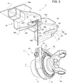
Figure 3 is an exploded perspective view of the support system offigure 2 ; -
Figure 4 is a side view of the support system offigure 2 cooperating with a rotary shaft system; -
Figure 5A is perspective view of the support according to the invention in a first operating configuration; -
Figure 5B is perspective view of the support according to the invention in a second operating configuration; and -
Figure 6 is a cross section view of the support offigure 5A . -
Figure 2 shows asupport system 1 for arotary shaft 2 according to the invention and basically comprising asupport 3 and ahousing element 4 for thesupport 3. Thesupport system 1 is configured to permit the adjustment of the position of thesupport 3 relative to thehousing element 4 and, hence, of therotary shaft 2 according to three degrees of freedom, as described more in detail below. - The degrees of freedom specifically comprise a linear movement of the
support 3 along a longitudinal axis A of therotary shaft 2, a linear movement of thesupport 3 along an axis B perpendicular to the axis A and a rotation of thesupport 3 around a transverse axis C perpendicular to the aforesaid axes A and B. - With reference to
figures 5A, 5B and6 , thesupport 3 is shown, which basically comprises anexternal structure 5, adamper 6 and arotating support 7; theexternal structure 5 is configured to house, on the inside, thedamper 6 and therotating support 7, as described more in detail below. - In particular, the
external structure 5 comprises acircular portion 5a with axis A, which is coaxial to the rotatingshaft 2, houses and defines acylindrical housing 8, which is axially open and is radially delimited by thecircular portion 5a. - The
external structure 5 further comprises a pair oflateral projections 5b extending from the outer edge of thecircular portion 5a parallel to the axis B in an opposite direction relative to the of therotary shaft 2. - In the case described herein, the
lateral projections 5b extend parallel to the axis B in a tangent manner relative to thecircular portion 5a and are preferably manufactured as separate elements relative to the latter and are fixed to it, for example through welding. - Furthermore, each
lateral projection 5b comprises abottom wall 11, which is tangent relative to thecentral portion 5a, and a pair oflateral walls 12, which extend from thebottom wall 11 perpendicularly to it in the direction of the axis A. - According to
figure 6 , thecylindrical housing 8 is configured to house, on the inside, thedamper 6 and therotating support 7. Thedamper 6 is a known damper, is made of a polymer material, has a substantially annular shape with dimensions that are such that the outer surface thereof can adhere to the inner surface of thecircular portion 5a and defines a housing to support therotating support 7. As it is known, furthermore, thedamper 6 comprises a plurality ofopenings 9, which are configured to give the damper 6 a suitable elasticity. Thedamper 6 will not be further described, for the sake of brevity, as it is already known. - The
rotating support 7 basically comprises a fixedportion 7a, which is provided with an outer portion adhering to an inner surface of thedamper 6, and a rotatingportion 7b, which is fixed to theshaft 2. In the case described herein, therotating support 7 comprises a bearing. - The
support 1 further comprises amobile portion 13, which is configured to cooperate, in a sliding manner, with theexternal structure 5, in particular with thelateral projections 5b. In particular, themobile portion 13 basically comprises acentral wall 14a with a substantially rectangular shape and a pair oflateral walls 14b extending perpendicularly relative to thecentral wall 14a starting from the lateral end edges thereof. Thecentral wall 14a and thelateral walls 14b are advantageously manufactured as one single piece. - The
lateral walls 14b are configured to cooperate, in a sliding manner, inside the space delimited by thebottom wall 11 and thelateral walls 12 of theprojections 5b and their extension along the axis A is such that themobile portion 13 can assume a first configuration (figure 5A ), in which thecentral wall 14a is at a minimum distance relative to thecentral portion 5a, and a second configuration (figure 5B ), in which thecentral wall 14a is at a maximum distance relative to thecentral portion 5a. - Owing to the above, the movement of the
mobile portion 13 relative to theprojections 5b is linear along the axis A; indeed, thelateral walls 14b are contained by thelateral walls 12 of theprojections 5b, which, hence, substantially create a linear guide for thelateral walls 14b. - The
support 3 further comprises movement means 16, which are configured to move themobile portion 13 relative to theexternal structure 5 so that it assumes all the positions between the two limit configurations described above and shown infigures 5A-5B . - The movement means 16 can advantageously comprise threaded means. In the case described herein, the movement means comprise a first threaded
element 17 carried by theexternal structure 5 and a second threadedelement 18 configured to cooperate with the first threadedelement 18 and carried by themobile portion 13. - More in detail, the first threaded
element 17 comprises a screw, which extends coaxial to the axis B from an apex end portion of thecentral portion 5b of theouter structure 5, to which it is fixed, for example, through welding, and goes through the central wall 14 of themobile portion 13. More in detail, again, the second threadedelement 18 comprises a nut-screw, which is externally coaxial to the aforesaid screw, has a thread that is such as to cooperate with the thread of the latter and is carried, in a rotationally free manner, by the central wall 14 of themobile portion 13. - Owing to the above, the central wall 14 defines an
opening 21, which is configured to house the nut-screw and the screw on the inside. In particular, the nut-screw comprises anupper portion 18a defining the threaded coupling with the screw and alower portion 18b, separated by agroove 22, configured to cooperate in a sliding manner, rotating along the axis B, with the central wall 14. Thelower portion 18b has greater dimensions than thehole 21 so as to define a snapping coupling with themobile portion 13. In this way, the nut-screw cannot move along the axis B, but can only rotate around it. - Each one of the
end portions 5b further defines aslot 23, which is obtained in thebottom wall 11 and extends longitudinally to it. Therefore, theslot 23 is delimited, along the axis A, by anupper stop wall 23a and by alower stop wall 23b. On the other hand, theslot 23 is laterally delimited so as to permit the passage of apin 24, which is carried by a substantially terminal portion of thelateral walls 14b of themobile portion 13. - In particular, the
pin 24 comprises amain portion 24a going through theslot 23 and extending parallel to the axis C on the outside thereof and anend portion 24b with greater dimensions than theslot 23 and placed on the opposite side relative to theslot 23 so as to prevent thepin 24 from freely moving outwards. - The
support 1 further comprises athrust element 26, which is carried on thepin 24 in a linearly mobile manner, and clamping means 25, which are configured to change the distance between thethrust element 26 and thebottom wall 11. - In the case described herein, the clamping means 25 comprise threaded means and, preferably, the
pin 24 is threaded like a screw and thethrust element 26 comprises a nut having a thread that is complementary to the one of thepin 24. As a consequence, thethrust element 26, by rotating, can move along the axis C defined by thepin 24. - It should be pointed out that the
mobile portion 13 is free to rotate around the axis C defined by the pair ofpins 24. In particular, with reference to the condition offigure 5B , theexternal structure 5 and all the elements contained by it can clearly pivot relative to themobile portion 13. - As already mentioned above, the
housing element 4 is configured to support thesupport 3, as described below and shown infigures 2 ,3 and4 . - The
housing element 4 basically comprises abracket 30, which is configured to be fixed to across member 31 of the frame of the vehicle. In particular, thebracket 30 comprises a fixingportion 30a, which is configured to allow thebracket 30 to be fixed to thecross member 31, which, in the case described herein, has an "L"-shaped cross section. Thebracket 30 further comprises a pair ofarms 30b, which are carried by the fixingportion 30a and extend from opposite ends thereof, in the case described herein, from the concave portion of the aforesaid "L"-shaped section. - The
arms 30b are spaced apart from one another so as to allow thesupport 3 to be housed. Furthermore, thearms 30b each define aguide 33, which is configured to house, in a sliding manner, thepins 24 of thesupport 3 described above, when it is inserted between them. In particular, eachguide 33 comprises aninput portion 33a and alinear portion 33b extending longitudinally inside therespective arm 30b. - In the example described herein, the
arms 30b substantially have the shape of a right trapezoid, in which the inclined side faces thecross member 31 and the lower side is linear. Thearms 30b advantageously comprise a main wall extending, as already mentioned above, from thecentral portion 30a and a reinforcement wall joining the aforesaid single wall. More in detail, according to a projection on the axis A, thearms 30b comprise the two aforesaid walls, which join one another so as to form a "V" shape and are flared along the axis A, from a maximum dimension of said walls, in the area where they join thecentral portion 30a, to a minimum dimension thereof, at the opposite end. - The
aforesaid guide 33 is advantageously obtained in the main wall of eacharm 30b and, more precisely, theaccess portion 33a communicates with the outside through the lower edge of the main wall, whereas thelongitudinal portion 33b is obtained in the main wall, but spaced apart from theaccess portion 33a. - In the embodiment described herein, the
guide 33 is "L"-shaped and, hence, defines three main positions for thepin 24, namely an input position 33' defined on the lower edge of the main wall of eacharm 30b, anangular position 33" at the crossing between theaccess portion 33a and thelongitudinal portion 33b and an end position 33''' at the end of thelongitudinal portion 33b on the opposite side relative to the input andangular positions 33', 33". - Once the
pin 24 has been inserted, through the rotation of the aforesaid nut, it can be locked in a desired position along thelongitudinal portion 33b of theguide 33. - The
housing element 4 further comprises stoppingmeans 35, which are configured to limit a possible travel of thepin 24 so as to prevent it from getting out of theinput portion 33a. - In particular, the stopping means 35 comprise a
flap 36, which is carried by the main wall of thearm 30b and is sized so as to allow thepin 24 to be inserted, when the clamping means 25 do not reduce the space between them and thewall 11 of themobile portion 13 of thesupport 3, and limit the movement thereof, when the clamping means 25 change said space by reducing it. In particular, according to the description, when the nut is not rotated on thepin 24, thesupport 3 can get into and out of theguide 33, otherwise theflap 36 prevents it from moving past theangular position 33". - In particular, in the case described herein, the
flap 36 is obtained by bending a free end of the main wall of thearm 30b defining theguide 33 in the direction of theopposite arm 30b. - In a use condition shown in
figure 4 , therotating shaft 2 is fixed on the inside of therotating support 7 of thesupport 3, which, in turn, is carried by thehousing element 4. Hence, theshaft 2 can keep extending past thesupport 7 or, like in the case described herein, be connected to anothershaft 2 by means of a joint 40. - The embodiment of the
support 3 and of the support system described above works as follows. - During a first step, which is not shown, the shaft support is mounted on the
shaft 2. - Before the installation on the overturned frame, the distance between the axis A of the
rotation shaft 2 and the axis C, i.e. from thepins 24, can conveniently be adjusted by means of the movement means 16, namely by acting upon the second threadedelement 18. In this way, since thepins 24 are fixed and, therefore, themobile element 13 is fixed, the nut-screw tends to move, through the screw, theexternal support 5 and, hence, lower (or lift) theshaft 2 along the axis B. - According to
figure 3 , then, thesupport 3 is moved so as to get into theguide 33 and longitudinally place itself in the provided position along the relativelongitudinal portion 33b, for example in theend portion 33"', as shown infigures 3 and4 . - During this operation, the clamping means 25 are not clamped and, therefore, the distance between the
thrust element 26 and thewall 11 of themobile portion 13 does not reach its maximum value. By so doing, thesupport 3 can be inserted into theguide 33 without interference with the stoppingmeans 35. - Once inserted in the longitudinal portion, the clamping means 25 can be partially clamped, so as to allow the
shaft 2 to move along the axis A, namely so that thepins 24 can place themselves in a different intermediate position between thepositions 33" and 33"', though without getting out of theangular position 33". Indeed, since the clamping means are partially clamped, the stopping means 35 interfere, if necessary, with thethrust element 26, thus stopping its movement towards theoutput portion 33a. - As to the inclination of the axis A around the axis C, it is automatically put in the least pulling condition for the damping element, since the
pins 24, as they are not completely clamped by themeans 35, can allow themobile portion 13 to move relative to theexternal support 5. - Once the flanges of the shaft have been connected to the flanges of the axle and of the gear-box, then the
support 3 can completely be fixed to thehousing element 4 by completely clamping the clamping means 25, namely by compressing on opposite sides - and, hence, fixing through friction - thewalls 11 of themobile portion 13, thelateral walls 5b of theexternal support 5 and the main wall of thearm 30b. - If, during use, there is an excess load along the axis B, for example a strong thrust towards the ground, the fact that the
slot 23 is closed at the top forbids a free and uncoupling movement of themobile portion 13 relative to theexternal structure 5. - If, during use, there is an excess load along the axis A, for example a strong thrust due to a sudden acceleration, the fact that the stopping means 35 prevent the clamping means 25 from moving when they are clamped prevents the
pins 24 from getting out of theguide 33. - Thanks to the device described above, it is also possible to use an alternative mounting method to mount a rotating shaft system, which is part of the invention and is described below.
- In particular, the mounting method to mount a system of
rotating shafts 2 by means of asupport system 1 of the type described above comprises the steps of: - Placing the
pins 24 of thesupport 3 in therespective guides 33 of thehousing element 4, while keeping the frame of the vehicle overturned; - Partially clamping the clamping means 25 so that the thrust means 26 prevent the
pins 24 from getting out of theguide 33; - Mounting an axle of the vehicle and the relative suspension and connecting the rear flange of the shaft to the input flange of the axle;
- Overturning the frame of the vehicle;
- Mounting an engine and a gear-box of the vehicle;
- Connecting the input flange of
rotating shafts 2 to the output flange of the gear-box; - adjusting possible clearances along the axis A of said
support 3, along the axis B and around the axis C of saidsupport 3 relative to thehousing element 4; - Completely clamping the clamping means 25 so as to lock the
support 3 relative to thehousing element 4. - The method can further comprise the preliminary steps of:
- Inserting a
rotating shaft 2 inside asupport 3; and/or - Pre-adjusting the height of the
axis A 2 relative to a design value by acting upon the movement means 16. - In particular, the adjustment of possible clearances along the axis A, along the axis B and around the axis C can comprise at least one of the following operations:
- Adjusting the position of the
pins 24 along theguides 33; - Adjusting the position of the
pins 24 relative to the fixedelement 31 relative to the frame by acting upon the moving means 16; and - Adjusting the inclination of the
external structure 5 relative to themobile portion 13 around the axis C. - Owing to the above, the advantages of a system for rotating shafts and of a relative method for mounting said shafts according to the invention are evident.
- Thanks to the
support system 1, the shaft can make large movements in a longitudinal direction, thus allowing, in case of use of rubber joints, the pin for the radial centring of the shaft to be introduced into the seat avoiding the use of an additional centring flange, which leads to a significant cost decrease. - Thanks to the
support system 1, furthermore, the position of arotating shaft 2 can be adjusted according to three degrees of freedom. In this way, it is possible to avoid mounting drawbacks and the tensions generated by them upon shifting of the vehicle and in thedamper 6 of thesupport 3. - In particular, the
support 3 is compact and has a shape that is substantially similar to the one of known systems, so that no further changes to the equipment of the vehicle in the frame are needed. - More in detail, the movement along the axis B avoids the use of the prior art spacers mentioned above and the need to adjust the support to different types and positions of cross members.
- Moreover, the movement along the axis A or around the axis C avoids the above-mentioned tensions upon shifting of the vehicle and in the
damper 6 of thesupport 3. - The use of clamping means 25 and threaded
elements 16 to adjust the position of thesupport 3 along the aforesaid degrees of freedom is simple and easy. - In addition, it is possible to offer
shafts 2 with apre-adjusted support 3, thus reducing the times needed to mount theshaft system 2 on the frame of the vehicle. - The fact that the
slots 23 are closed and theguides 33 are provided with stoppingmeans 35 allows thesupport 3 to be moved along the axes A and B in a safe manner, even in case of overloads of the shafts that can give sudden impulses to thesupport system 1. In this way, theshaft 2 is always kept connected to the frame. - Furthermore, the mounting method that can be used thanks to the aforesaid support is less time-consuming and more economic.
- Indeed, the shaft system can be mounted in a safe manner, with no preliminary fixing. The
shaft system 2 can be adjusted in a practically automatic manner; indeed, once all the necessary elements are mounted, the weight of therotating shafts 2 tends to self-balance the system relative to the aforesaid three degrees of freedom. Then, the clamping means 25 simply need to be clamped in order to secure the ideal configuration. - The clamping will be very quick, since the
thrust elements 26, namely the nuts, are already mounted on thepins 24. - Furthermore, the aforesaid time and cost reductions are obtained by eliminating the times of those steps that are no longer needed, for example the spacer selection, position and adjusted steps, as well as by eliminating screws and spacers, which are now absent.
- Finally, it is clear that the support system for rotating shafts and the relative shaft mounting method according to the invention can be subjected to changes and variants, which, though, do not go beyond the scope of protection set forth in the appended claims.
- For example, the shape of the
bracket 30 or the features of therotating support 7 or of thedamper 6 can be changed based on the type of vehicle andshaft 2. - Moreover, in some applications, the
slots 23 could be open at the top and the stopping means 35 could be absent. - Finally, the movement means 16, the clamping means 25 or the stopping means 35 could be replaced by elements having the same function.
Claims (17)
- A support system (1) for a shaft (2) of a vehicle, said support system (1) comprising a support (3) and a housing element (4), the latter being configured to be fixed to an element (30) fixed with respect to a frame of said vehicle, said support (3) being configured to support said shaft (2) in a rotationally free manner, said support (3) and said housing element (4) cooperating with one another to define a first configuration, wherein said support (3) is fixed with respect to said housing element (4) and a second configuration in which said support (3) is carried by said housing element (4) in a mobile manner with respect to three degrees of freedom.
- The support system according to claim 1, wherein said degrees of freedom of said support (3) comprise a linear movement along a longitudinal axis (A) of said shaft (2), a linear movement along an axis (B) perpendicular to said axis (A) and a rotation around an axis (C) perpendicular to said axes (A, B).
- The support system according to claim 2, wherein said housing element (4) comprises a pair of arms (30b) fixable to said element (30) fixed with respect to said frame, said arms (30b) being spaced from one another to house said support (3) therein and defining respective guides (33) extending along said axis (A), said support (3) comprising an external structure (5) configured to house said shaft (2) therein in a rotating manner and a mobile portion (13) in a linear manner along said axis (B) with respect to said external structure (5), said support (3) comprising a portion (13) mobile with respect to said external structure (5) and a pair of pins (24) carried rigidly by said mobile portion (13), said pins (24) being configured to cooperate in contact with said arms (30b) inside said guides (33) to move along said axis (A) and to enable a rotation of said support (3) with respect to said housing element (4) around said axis (C).
- The support system according to claim 3, comprising clamping means (25) configured to couple said mobile element (13), said external structure (5) and said arms (30b) to one another by friction,
when said elements are decoupled from one another, said support (3) is free to move along the said three degrees of freedom with respect to said housing element (4),
when said elements are coupled to one another, said support (3) is fixed with respect to said housing element (4) . - The system according to claim 4, wherein said clamping means (25) comprise threaded elements.
- The system according to claim 4 or 5, wherein said clamping means (25) comprise a thrust element (26) configured to move linearly along the respective pin (24).
- The system according to one of the claims from 3 to 6, wherein said support (3) comprises movement means (16) configured to move said mobile portion (13) with respect to said external structure (5).
- The system according to claim 7, wherein said movement means (16) comprise threaded elements.
- The system according to claim 7 or 8, wherein said movement means (16) comprise a screw (17) carried by one between said mobile portion (13) and said external structure (5) and a nut-screw (18) carried by the other between said mobile portion (13) and said external structure (5), said screw (17) and said nut-screw (17, 18) cooperating with one another to move said mobile portion (13) with respect to said external structure (5).
- The system according to one of the claims from 3 to 9, wherein said external structure (5) defines a pair of slots (23) configured to house said pins (24) in the movement of said mobile portion (13) along said axis (B) with respect to said external structure (5), each of said slots defining a top end stroke (23a) and a bottom end stroke (23b) configured to limit said movement of said mobile portion (13) along said axis (B).
- The system according to one of the claims from 4 to 10, comprising stopping means (35) configured to selectively enable said support (3) to exit said guides (33) of said housing element (4).
- The system according to claim 11, wherein said stopping means (35) comprise a flap (36) sized so as to enable the insertion of said support (3) in said guides (33) when said clamping means (25) are not clamped and to prevent said support (3) from exiting said guides (33) when said clamping means (25) are at least partially clamped.
- The support system according to one of the preceding claims wherein said support (3) comprises a rotating support (7) for said shaft (2) and dampening means (8) interposed between said rotating support (7) and said external structure (5).
- A vehicle comprising a frame and a shaft (2) fixed to said frame by means of at least a support system according to one of the preceding claims.
- A method for mounting a system of rotating shafts (2) through a support system (1) according to any one of the preceding claims and comprising the steps of:• Positioning pins (24) of said support (3) in the respective guides (33) of said housing element (4), by keeping a frame of said vehicle overturned;• Partially clamping the clamping means (25) so that the thrust means (26) prevent said pins (24) from exiting said guides (33);• Overturning said frame of said vehicle;• Mounting an engine and gear-box of said vehicle on said frame;• Mounting said system of rotating shafts (2) to said engine and gear-box;• Adjusting possible clearances along the axis A of said rotating shafts (2), along the axis (B) and around the axis (C) of said supports (3) with respect to said housing element (4); and• Completely clamping said clamping means (25) in order to lock said support (3) with respect to said housing element (4).
- The method according to claim 15, further comprising at least one of the following preliminary steps of:• Mounting said support (3) on a shaft (2);• Pre-recording the height of said axis (A) with respect to a drawing value acting on said movement means (16).
- The method according to claim 15 or 16, wherein said adjustment comprises at least one of the following operations:• Adjusting the position of said pins (24) along said guides (33);• Adjusting the position between said pins (24) and said element (30) fixed to said frame;• Adjusting the inclination around the axis (C) of said support (3) with respect to said housing element (4).
Applications Claiming Priority (1)
| Application Number | Priority Date | Filing Date | Title |
|---|---|---|---|
| IT102019000014424A IT201900014424A1 (en) | 2019-08-08 | 2019-08-08 | SUPPORT SYSTEM FOR A VEHICLE DRIVE SHAFT AND RELEVANT MOUNTING METHOD FOR A VEHICLE DRIVE SHAFT |
Publications (2)
| Publication Number | Publication Date |
|---|---|
| EP3772426A1 true EP3772426A1 (en) | 2021-02-10 |
| EP3772426B1 EP3772426B1 (en) | 2024-04-03 |
Family
ID=69106009
Family Applications (1)
| Application Number | Title | Priority Date | Filing Date |
|---|---|---|---|
| EP20189630.5A Active EP3772426B1 (en) | 2019-08-08 | 2020-08-05 | Support system for a vehicle transmission shaft and related mounting method for a vehicle transmission shaft |
Country Status (2)
| Country | Link |
|---|---|
| EP (1) | EP3772426B1 (en) |
| IT (1) | IT201900014424A1 (en) |
Cited By (1)
| Publication number | Priority date | Publication date | Assignee | Title |
|---|---|---|---|---|
| CN115467957A (en) * | 2022-09-28 | 2022-12-13 | 天津特智履研究开发有限公司 | A stable clamping structure for the main shaft of an engineering vehicle |
Citations (4)
| Publication number | Priority date | Publication date | Assignee | Title |
|---|---|---|---|---|
| DE69116845T2 (en) * | 1991-01-03 | 1996-09-05 | Ind E Com De Auto Pecas Rei | Bearing support |
| CN203331830U (en) * | 2013-07-12 | 2013-12-11 | 许昌远东传动轴股份有限公司 | Middle supporting device of transmission shaft |
| KR101693893B1 (en) * | 2011-12-09 | 2017-01-09 | 현대자동차주식회사 | Assembly for supporting center bearing of propeller shaft |
| CN107054078A (en) * | 2017-05-16 | 2017-08-18 | 翟秀强 | A kind of flexible intermediate strutting device of adjustable power transmission shaft |
-
2019
- 2019-08-08 IT IT102019000014424A patent/IT201900014424A1/en unknown
-
2020
- 2020-08-05 EP EP20189630.5A patent/EP3772426B1/en active Active
Patent Citations (4)
| Publication number | Priority date | Publication date | Assignee | Title |
|---|---|---|---|---|
| DE69116845T2 (en) * | 1991-01-03 | 1996-09-05 | Ind E Com De Auto Pecas Rei | Bearing support |
| KR101693893B1 (en) * | 2011-12-09 | 2017-01-09 | 현대자동차주식회사 | Assembly for supporting center bearing of propeller shaft |
| CN203331830U (en) * | 2013-07-12 | 2013-12-11 | 许昌远东传动轴股份有限公司 | Middle supporting device of transmission shaft |
| CN107054078A (en) * | 2017-05-16 | 2017-08-18 | 翟秀强 | A kind of flexible intermediate strutting device of adjustable power transmission shaft |
Cited By (1)
| Publication number | Priority date | Publication date | Assignee | Title |
|---|---|---|---|---|
| CN115467957A (en) * | 2022-09-28 | 2022-12-13 | 天津特智履研究开发有限公司 | A stable clamping structure for the main shaft of an engineering vehicle |
Also Published As
| Publication number | Publication date |
|---|---|
| IT201900014424A1 (en) | 2021-02-08 |
| EP3772426B1 (en) | 2024-04-03 |
Similar Documents
| Publication | Publication Date | Title |
|---|---|---|
| US7971505B2 (en) | Link actuating device | |
| US8777794B2 (en) | Geared motor | |
| US5098068A (en) | Lifting machinery | |
| EP0584400B1 (en) | Shaft coupling | |
| EP1065132A1 (en) | Electric power steering apparatus | |
| DE102011113437B4 (en) | Clutch and motor | |
| KR20010072160A (en) | Drive device having motor and speed reduction mechanism | |
| JPH05141413A (en) | Bearing assembly | |
| US4421187A (en) | Transmission with alignable bearing supporting longer power output shaft of differential | |
| KR20010090585A (en) | One piece differential bearing adjuster lock and fastener | |
| EP3772426B1 (en) | Support system for a vehicle transmission shaft and related mounting method for a vehicle transmission shaft | |
| US11415185B2 (en) | Reverse-input blocking clutch | |
| EP1086838A1 (en) | Structure and method for mounting damper | |
| EP3351817A1 (en) | Slip yoke assembly | |
| MXPA02004384A (en) | Arrangement for clamping inner bearing race to non-circular section shaft and for preventing axial load in the bearing, axial creep and rotational knock. | |
| US6383081B1 (en) | Spider for use in a compact universal joint assembly | |
| GB2261199A (en) | Angled vehicle axle assembly. | |
| EP0636805B1 (en) | Shaft coupling | |
| US8047946B2 (en) | Differential case for vehicle and differential device for vehicle including differential case | |
| US5921569A (en) | Torsion bar positioning structure | |
| WO2025114443A1 (en) | Drive arrangement for adjusting a flap of a motor vehicle | |
| CA2288512C (en) | Pivoting mounting block for motorized conveyor pulleys | |
| US20090044649A1 (en) | Spur Gear Transmission | |
| US5644955A (en) | Structure for supporting driving reaction force on differential housing | |
| EP2887506B1 (en) | Torque support |
Legal Events
| Date | Code | Title | Description |
|---|---|---|---|
| PUAI | Public reference made under article 153(3) epc to a published international application that has entered the european phase |
Free format text: ORIGINAL CODE: 0009012 |
|
| STAA | Information on the status of an ep patent application or granted ep patent |
Free format text: STATUS: THE APPLICATION HAS BEEN PUBLISHED |
|
| AK | Designated contracting states |
Kind code of ref document: A1 Designated state(s): AL AT BE BG CH CY CZ DE DK EE ES FI FR GB GR HR HU IE IS IT LI LT LU LV MC MK MT NL NO PL PT RO RS SE SI SK SM TR |
|
| AX | Request for extension of the european patent |
Extension state: BA ME |
|
| STAA | Information on the status of an ep patent application or granted ep patent |
Free format text: STATUS: REQUEST FOR EXAMINATION WAS MADE |
|
| 17P | Request for examination filed |
Effective date: 20210705 |
|
| RBV | Designated contracting states (corrected) |
Designated state(s): AL AT BE BG CH CY CZ DE DK EE ES FI FR GB GR HR HU IE IS IT LI LT LU LV MC MK MT NL NO PL PT RO RS SE SI SK SM TR |
|
| STAA | Information on the status of an ep patent application or granted ep patent |
Free format text: STATUS: EXAMINATION IS IN PROGRESS |
|
| 17Q | First examination report despatched |
Effective date: 20211118 |
|
| GRAP | Despatch of communication of intention to grant a patent |
Free format text: ORIGINAL CODE: EPIDOSNIGR1 |
|
| STAA | Information on the status of an ep patent application or granted ep patent |
Free format text: STATUS: GRANT OF PATENT IS INTENDED |
|
| INTG | Intention to grant announced |
Effective date: 20231023 |
|
| P01 | Opt-out of the competence of the unified patent court (upc) registered |
Effective date: 20231214 |
|
| GRAS | Grant fee paid |
Free format text: ORIGINAL CODE: EPIDOSNIGR3 |
|
| GRAA | (expected) grant |
Free format text: ORIGINAL CODE: 0009210 |
|
| STAA | Information on the status of an ep patent application or granted ep patent |
Free format text: STATUS: THE PATENT HAS BEEN GRANTED |
|
| AK | Designated contracting states |
Kind code of ref document: B1 Designated state(s): AL AT BE BG CH CY CZ DE DK EE ES FI FR GB GR HR HU IE IS IT LI LT LU LV MC MK MT NL NO PL PT RO RS SE SI SK SM TR |
|
| REG | Reference to a national code |
Ref country code: DE Ref legal event code: R082 Ref document number: 602020028215 Country of ref document: DE Representative=s name: TER MEER STEINMEISTER & PARTNER PATENTANWAELTE, DE |
|
| REG | Reference to a national code |
Ref country code: CH Ref legal event code: EP |
|
| REG | Reference to a national code |
Ref country code: DE Ref legal event code: R096 Ref document number: 602020028215 Country of ref document: DE |
|
| REG | Reference to a national code |
Ref country code: IE Ref legal event code: FG4D |
|
| REG | Reference to a national code |
Ref country code: LT Ref legal event code: MG9D |
|
| REG | Reference to a national code |
Ref country code: NL Ref legal event code: MP Effective date: 20240403 |
|
| REG | Reference to a national code |
Ref country code: AT Ref legal event code: MK05 Ref document number: 1671910 Country of ref document: AT Kind code of ref document: T Effective date: 20240403 |
|
| PG25 | Lapsed in a contracting state [announced via postgrant information from national office to epo] |
Ref country code: NL Free format text: LAPSE BECAUSE OF FAILURE TO SUBMIT A TRANSLATION OF THE DESCRIPTION OR TO PAY THE FEE WITHIN THE PRESCRIBED TIME-LIMIT Effective date: 20240403 |
|
| PG25 | Lapsed in a contracting state [announced via postgrant information from national office to epo] |
Ref country code: NL Free format text: LAPSE BECAUSE OF FAILURE TO SUBMIT A TRANSLATION OF THE DESCRIPTION OR TO PAY THE FEE WITHIN THE PRESCRIBED TIME-LIMIT Effective date: 20240403 |
|
| PG25 | Lapsed in a contracting state [announced via postgrant information from national office to epo] |
Ref country code: IS Free format text: LAPSE BECAUSE OF FAILURE TO SUBMIT A TRANSLATION OF THE DESCRIPTION OR TO PAY THE FEE WITHIN THE PRESCRIBED TIME-LIMIT Effective date: 20240803 |
|
| PG25 | Lapsed in a contracting state [announced via postgrant information from national office to epo] |
Ref country code: BG Free format text: LAPSE BECAUSE OF FAILURE TO SUBMIT A TRANSLATION OF THE DESCRIPTION OR TO PAY THE FEE WITHIN THE PRESCRIBED TIME-LIMIT Effective date: 20240403 |
|
| PG25 | Lapsed in a contracting state [announced via postgrant information from national office to epo] |
Ref country code: FI Free format text: LAPSE BECAUSE OF FAILURE TO SUBMIT A TRANSLATION OF THE DESCRIPTION OR TO PAY THE FEE WITHIN THE PRESCRIBED TIME-LIMIT Effective date: 20240403 Ref country code: HR Free format text: LAPSE BECAUSE OF FAILURE TO SUBMIT A TRANSLATION OF THE DESCRIPTION OR TO PAY THE FEE WITHIN THE PRESCRIBED TIME-LIMIT Effective date: 20240403 |
|
| PG25 | Lapsed in a contracting state [announced via postgrant information from national office to epo] |
Ref country code: GR Free format text: LAPSE BECAUSE OF FAILURE TO SUBMIT A TRANSLATION OF THE DESCRIPTION OR TO PAY THE FEE WITHIN THE PRESCRIBED TIME-LIMIT Effective date: 20240704 |
|
| PG25 | Lapsed in a contracting state [announced via postgrant information from national office to epo] |
Ref country code: PT Free format text: LAPSE BECAUSE OF FAILURE TO SUBMIT A TRANSLATION OF THE DESCRIPTION OR TO PAY THE FEE WITHIN THE PRESCRIBED TIME-LIMIT Effective date: 20240805 |
|
| PG25 | Lapsed in a contracting state [announced via postgrant information from national office to epo] |
Ref country code: ES Free format text: LAPSE BECAUSE OF FAILURE TO SUBMIT A TRANSLATION OF THE DESCRIPTION OR TO PAY THE FEE WITHIN THE PRESCRIBED TIME-LIMIT Effective date: 20240403 |
|
| PG25 | Lapsed in a contracting state [announced via postgrant information from national office to epo] |
Ref country code: CZ Free format text: LAPSE BECAUSE OF FAILURE TO SUBMIT A TRANSLATION OF THE DESCRIPTION OR TO PAY THE FEE WITHIN THE PRESCRIBED TIME-LIMIT Effective date: 20240403 |
|
| PG25 | Lapsed in a contracting state [announced via postgrant information from national office to epo] |
Ref country code: AT Free format text: LAPSE BECAUSE OF FAILURE TO SUBMIT A TRANSLATION OF THE DESCRIPTION OR TO PAY THE FEE WITHIN THE PRESCRIBED TIME-LIMIT Effective date: 20240403 |
|
| PG25 | Lapsed in a contracting state [announced via postgrant information from national office to epo] |
Ref country code: PL Free format text: LAPSE BECAUSE OF FAILURE TO SUBMIT A TRANSLATION OF THE DESCRIPTION OR TO PAY THE FEE WITHIN THE PRESCRIBED TIME-LIMIT Effective date: 20240403 |
|
| PG25 | Lapsed in a contracting state [announced via postgrant information from national office to epo] |
Ref country code: LV Free format text: LAPSE BECAUSE OF FAILURE TO SUBMIT A TRANSLATION OF THE DESCRIPTION OR TO PAY THE FEE WITHIN THE PRESCRIBED TIME-LIMIT Effective date: 20240403 |
|
| PG25 | Lapsed in a contracting state [announced via postgrant information from national office to epo] |
Ref country code: PT Free format text: LAPSE BECAUSE OF FAILURE TO SUBMIT A TRANSLATION OF THE DESCRIPTION OR TO PAY THE FEE WITHIN THE PRESCRIBED TIME-LIMIT Effective date: 20240805 Ref country code: PL Free format text: LAPSE BECAUSE OF FAILURE TO SUBMIT A TRANSLATION OF THE DESCRIPTION OR TO PAY THE FEE WITHIN THE PRESCRIBED TIME-LIMIT Effective date: 20240403 Ref country code: NO Free format text: LAPSE BECAUSE OF FAILURE TO SUBMIT A TRANSLATION OF THE DESCRIPTION OR TO PAY THE FEE WITHIN THE PRESCRIBED TIME-LIMIT Effective date: 20240703 Ref country code: LV Free format text: LAPSE BECAUSE OF FAILURE TO SUBMIT A TRANSLATION OF THE DESCRIPTION OR TO PAY THE FEE WITHIN THE PRESCRIBED TIME-LIMIT Effective date: 20240403 Ref country code: IS Free format text: LAPSE BECAUSE OF FAILURE TO SUBMIT A TRANSLATION OF THE DESCRIPTION OR TO PAY THE FEE WITHIN THE PRESCRIBED TIME-LIMIT Effective date: 20240803 Ref country code: HR Free format text: LAPSE BECAUSE OF FAILURE TO SUBMIT A TRANSLATION OF THE DESCRIPTION OR TO PAY THE FEE WITHIN THE PRESCRIBED TIME-LIMIT Effective date: 20240403 Ref country code: GR Free format text: LAPSE BECAUSE OF FAILURE TO SUBMIT A TRANSLATION OF THE DESCRIPTION OR TO PAY THE FEE WITHIN THE PRESCRIBED TIME-LIMIT Effective date: 20240704 Ref country code: FI Free format text: LAPSE BECAUSE OF FAILURE TO SUBMIT A TRANSLATION OF THE DESCRIPTION OR TO PAY THE FEE WITHIN THE PRESCRIBED TIME-LIMIT Effective date: 20240403 Ref country code: ES Free format text: LAPSE BECAUSE OF FAILURE TO SUBMIT A TRANSLATION OF THE DESCRIPTION OR TO PAY THE FEE WITHIN THE PRESCRIBED TIME-LIMIT Effective date: 20240403 Ref country code: CZ Free format text: LAPSE BECAUSE OF FAILURE TO SUBMIT A TRANSLATION OF THE DESCRIPTION OR TO PAY THE FEE WITHIN THE PRESCRIBED TIME-LIMIT Effective date: 20240403 Ref country code: BG Free format text: LAPSE BECAUSE OF FAILURE TO SUBMIT A TRANSLATION OF THE DESCRIPTION OR TO PAY THE FEE WITHIN THE PRESCRIBED TIME-LIMIT Effective date: 20240403 Ref country code: AT Free format text: LAPSE BECAUSE OF FAILURE TO SUBMIT A TRANSLATION OF THE DESCRIPTION OR TO PAY THE FEE WITHIN THE PRESCRIBED TIME-LIMIT Effective date: 20240403 Ref country code: RS Free format text: LAPSE BECAUSE OF FAILURE TO SUBMIT A TRANSLATION OF THE DESCRIPTION OR TO PAY THE FEE WITHIN THE PRESCRIBED TIME-LIMIT Effective date: 20240703 |
|
| REG | Reference to a national code |
Ref country code: DE Ref legal event code: R097 Ref document number: 602020028215 Country of ref document: DE |
|
| PG25 | Lapsed in a contracting state [announced via postgrant information from national office to epo] |
Ref country code: DK Free format text: LAPSE BECAUSE OF FAILURE TO SUBMIT A TRANSLATION OF THE DESCRIPTION OR TO PAY THE FEE WITHIN THE PRESCRIBED TIME-LIMIT Effective date: 20240403 |
|
| PG25 | Lapsed in a contracting state [announced via postgrant information from national office to epo] |
Ref country code: EE Free format text: LAPSE BECAUSE OF FAILURE TO SUBMIT A TRANSLATION OF THE DESCRIPTION OR TO PAY THE FEE WITHIN THE PRESCRIBED TIME-LIMIT Effective date: 20240403 |
|
| PG25 | Lapsed in a contracting state [announced via postgrant information from national office to epo] |
Ref country code: SK Free format text: LAPSE BECAUSE OF FAILURE TO SUBMIT A TRANSLATION OF THE DESCRIPTION OR TO PAY THE FEE WITHIN THE PRESCRIBED TIME-LIMIT Effective date: 20240403 Ref country code: RO Free format text: LAPSE BECAUSE OF FAILURE TO SUBMIT A TRANSLATION OF THE DESCRIPTION OR TO PAY THE FEE WITHIN THE PRESCRIBED TIME-LIMIT Effective date: 20240403 |
|
| PG25 | Lapsed in a contracting state [announced via postgrant information from national office to epo] |
Ref country code: SM Free format text: LAPSE BECAUSE OF FAILURE TO SUBMIT A TRANSLATION OF THE DESCRIPTION OR TO PAY THE FEE WITHIN THE PRESCRIBED TIME-LIMIT Effective date: 20240403 |
|
| PG25 | Lapsed in a contracting state [announced via postgrant information from national office to epo] |
Ref country code: SM Free format text: LAPSE BECAUSE OF FAILURE TO SUBMIT A TRANSLATION OF THE DESCRIPTION OR TO PAY THE FEE WITHIN THE PRESCRIBED TIME-LIMIT Effective date: 20240403 Ref country code: SK Free format text: LAPSE BECAUSE OF FAILURE TO SUBMIT A TRANSLATION OF THE DESCRIPTION OR TO PAY THE FEE WITHIN THE PRESCRIBED TIME-LIMIT Effective date: 20240403 Ref country code: RO Free format text: LAPSE BECAUSE OF FAILURE TO SUBMIT A TRANSLATION OF THE DESCRIPTION OR TO PAY THE FEE WITHIN THE PRESCRIBED TIME-LIMIT Effective date: 20240403 Ref country code: EE Free format text: LAPSE BECAUSE OF FAILURE TO SUBMIT A TRANSLATION OF THE DESCRIPTION OR TO PAY THE FEE WITHIN THE PRESCRIBED TIME-LIMIT Effective date: 20240403 Ref country code: DK Free format text: LAPSE BECAUSE OF FAILURE TO SUBMIT A TRANSLATION OF THE DESCRIPTION OR TO PAY THE FEE WITHIN THE PRESCRIBED TIME-LIMIT Effective date: 20240403 |
|
| PLBE | No opposition filed within time limit |
Free format text: ORIGINAL CODE: 0009261 |
|
| STAA | Information on the status of an ep patent application or granted ep patent |
Free format text: STATUS: NO OPPOSITION FILED WITHIN TIME LIMIT |
|
| 26N | No opposition filed |
Effective date: 20250106 |
|
| REG | Reference to a national code |
Ref country code: CH Ref legal event code: PL |
|
| PG25 | Lapsed in a contracting state [announced via postgrant information from national office to epo] |
Ref country code: LU Free format text: LAPSE BECAUSE OF NON-PAYMENT OF DUE FEES Effective date: 20240805 |
|
| GBPC | Gb: european patent ceased through non-payment of renewal fee |
Effective date: 20240805 |
|
| PG25 | Lapsed in a contracting state [announced via postgrant information from national office to epo] |
Ref country code: SI Free format text: LAPSE BECAUSE OF FAILURE TO SUBMIT A TRANSLATION OF THE DESCRIPTION OR TO PAY THE FEE WITHIN THE PRESCRIBED TIME-LIMIT Effective date: 20240403 Ref country code: CH Free format text: LAPSE BECAUSE OF NON-PAYMENT OF DUE FEES Effective date: 20240831 Ref country code: MC Free format text: LAPSE BECAUSE OF FAILURE TO SUBMIT A TRANSLATION OF THE DESCRIPTION OR TO PAY THE FEE WITHIN THE PRESCRIBED TIME-LIMIT Effective date: 20240403 |
|
| REG | Reference to a national code |
Ref country code: BE Ref legal event code: MM Effective date: 20240831 |
|
| PG25 | Lapsed in a contracting state [announced via postgrant information from national office to epo] |
Ref country code: GB Free format text: LAPSE BECAUSE OF NON-PAYMENT OF DUE FEES Effective date: 20240805 |
|
| PG25 | Lapsed in a contracting state [announced via postgrant information from national office to epo] |
Ref country code: BE Free format text: LAPSE BECAUSE OF NON-PAYMENT OF DUE FEES Effective date: 20240831 |
|
| PG25 | Lapsed in a contracting state [announced via postgrant information from national office to epo] |
Ref country code: IE Free format text: LAPSE BECAUSE OF NON-PAYMENT OF DUE FEES Effective date: 20240805 |
|
| PG25 | Lapsed in a contracting state [announced via postgrant information from national office to epo] |
Ref country code: SE Free format text: LAPSE BECAUSE OF FAILURE TO SUBMIT A TRANSLATION OF THE DESCRIPTION OR TO PAY THE FEE WITHIN THE PRESCRIBED TIME-LIMIT Effective date: 20240403 |
|
| PGFP | Annual fee paid to national office [announced via postgrant information from national office to epo] |
Ref country code: DE Payment date: 20250827 Year of fee payment: 6 |
|
| PGFP | Annual fee paid to national office [announced via postgrant information from national office to epo] |
Ref country code: FR Payment date: 20250825 Year of fee payment: 6 |
|
| PG25 | Lapsed in a contracting state [announced via postgrant information from national office to epo] |
Ref country code: IT Free format text: LAPSE BECAUSE OF NON-PAYMENT OF DUE FEES Effective date: 20240805 |
|
| PG25 | Lapsed in a contracting state [announced via postgrant information from national office to epo] |
Ref country code: CY Free format text: LAPSE BECAUSE OF FAILURE TO SUBMIT A TRANSLATION OF THE DESCRIPTION OR TO PAY THE FEE WITHIN THE PRESCRIBED TIME-LIMIT; INVALID AB INITIO Effective date: 20200805 |
|
| PG25 | Lapsed in a contracting state [announced via postgrant information from national office to epo] |
Ref country code: HU Free format text: LAPSE BECAUSE OF FAILURE TO SUBMIT A TRANSLATION OF THE DESCRIPTION OR TO PAY THE FEE WITHIN THE PRESCRIBED TIME-LIMIT; INVALID AB INITIO Effective date: 20200805 |
|
| PG25 | Lapsed in a contracting state [announced via postgrant information from national office to epo] |
Ref country code: IT Free format text: LAPSE BECAUSE OF NON-PAYMENT OF DUE FEES Effective date: 20240805 |
|
| PGFP | Annual fee paid to national office [announced via postgrant information from national office to epo] |
Ref country code: IT Payment date: 20250714 Year of fee payment: 6 |
|
| PGRI | Patent reinstated in contracting state [announced from national office to epo] |
Ref country code: IT Effective date: 20241231 |